EP3369976A1 - Valve device and steam turbine equipment - Google Patents
Valve device and steam turbine equipment Download PDFInfo
- Publication number
- EP3369976A1 EP3369976A1 EP15907244.6A EP15907244A EP3369976A1 EP 3369976 A1 EP3369976 A1 EP 3369976A1 EP 15907244 A EP15907244 A EP 15907244A EP 3369976 A1 EP3369976 A1 EP 3369976A1
- Authority
- EP
- European Patent Office
- Prior art keywords
- valve
- steam
- flow channel
- steam turbine
- valve body
- Prior art date
- Legal status (The legal status is an assumption and is not a legal conclusion. Google has not performed a legal analysis and makes no representation as to the accuracy of the status listed.)
- Granted
Links
Images

Classifications
-
- F—MECHANICAL ENGINEERING; LIGHTING; HEATING; WEAPONS; BLASTING
- F01—MACHINES OR ENGINES IN GENERAL; ENGINE PLANTS IN GENERAL; STEAM ENGINES
- F01D—NON-POSITIVE DISPLACEMENT MACHINES OR ENGINES, e.g. STEAM TURBINES
- F01D17/00—Regulating or controlling by varying flow
- F01D17/10—Final actuators
-
- F—MECHANICAL ENGINEERING; LIGHTING; HEATING; WEAPONS; BLASTING
- F01—MACHINES OR ENGINES IN GENERAL; ENGINE PLANTS IN GENERAL; STEAM ENGINES
- F01D—NON-POSITIVE DISPLACEMENT MACHINES OR ENGINES, e.g. STEAM TURBINES
- F01D17/00—Regulating or controlling by varying flow
- F01D17/10—Final actuators
- F01D17/12—Final actuators arranged in stator parts
-
- F—MECHANICAL ENGINEERING; LIGHTING; HEATING; WEAPONS; BLASTING
- F01—MACHINES OR ENGINES IN GENERAL; ENGINE PLANTS IN GENERAL; STEAM ENGINES
- F01D—NON-POSITIVE DISPLACEMENT MACHINES OR ENGINES, e.g. STEAM TURBINES
- F01D17/00—Regulating or controlling by varying flow
- F01D17/10—Final actuators
- F01D17/12—Final actuators arranged in stator parts
- F01D17/18—Final actuators arranged in stator parts varying effective number of nozzles or guide conduits, e.g. sequentially operable valves for steam turbines
-
- F—MECHANICAL ENGINEERING; LIGHTING; HEATING; WEAPONS; BLASTING
- F16—ENGINEERING ELEMENTS AND UNITS; GENERAL MEASURES FOR PRODUCING AND MAINTAINING EFFECTIVE FUNCTIONING OF MACHINES OR INSTALLATIONS; THERMAL INSULATION IN GENERAL
- F16K—VALVES; TAPS; COCKS; ACTUATING-FLOATS; DEVICES FOR VENTING OR AERATING
- F16K11/00—Multiple-way valves, e.g. mixing valves; Pipe fittings incorporating such valves
- F16K11/10—Multiple-way valves, e.g. mixing valves; Pipe fittings incorporating such valves with two or more closure members not moving as a unit
- F16K11/14—Multiple-way valves, e.g. mixing valves; Pipe fittings incorporating such valves with two or more closure members not moving as a unit operated by one actuating member, e.g. a handle
- F16K11/16—Multiple-way valves, e.g. mixing valves; Pipe fittings incorporating such valves with two or more closure members not moving as a unit operated by one actuating member, e.g. a handle which only slides, or only turns, or only swings in one plane
-
- F—MECHANICAL ENGINEERING; LIGHTING; HEATING; WEAPONS; BLASTING
- F16—ENGINEERING ELEMENTS AND UNITS; GENERAL MEASURES FOR PRODUCING AND MAINTAINING EFFECTIVE FUNCTIONING OF MACHINES OR INSTALLATIONS; THERMAL INSULATION IN GENERAL
- F16K—VALVES; TAPS; COCKS; ACTUATING-FLOATS; DEVICES FOR VENTING OR AERATING
- F16K31/00—Actuating devices; Operating means; Releasing devices
- F16K31/44—Mechanical actuating means
-
- F—MECHANICAL ENGINEERING; LIGHTING; HEATING; WEAPONS; BLASTING
- F16—ENGINEERING ELEMENTS AND UNITS; GENERAL MEASURES FOR PRODUCING AND MAINTAINING EFFECTIVE FUNCTIONING OF MACHINES OR INSTALLATIONS; THERMAL INSULATION IN GENERAL
- F16K—VALVES; TAPS; COCKS; ACTUATING-FLOATS; DEVICES FOR VENTING OR AERATING
- F16K31/00—Actuating devices; Operating means; Releasing devices
- F16K31/44—Mechanical actuating means
- F16K31/52—Mechanical actuating means with crank, eccentric, or cam
- F16K31/528—Mechanical actuating means with crank, eccentric, or cam with pin and slot
-
- F—MECHANICAL ENGINEERING; LIGHTING; HEATING; WEAPONS; BLASTING
- F05—INDEXING SCHEMES RELATING TO ENGINES OR PUMPS IN VARIOUS SUBCLASSES OF CLASSES F01-F04
- F05D—INDEXING SCHEME FOR ASPECTS RELATING TO NON-POSITIVE-DISPLACEMENT MACHINES OR ENGINES, GAS-TURBINES OR JET-PROPULSION PLANTS
- F05D2220/00—Application
- F05D2220/30—Application in turbines
- F05D2220/31—Application in turbines in steam turbines
-
- G—PHYSICS
- G05—CONTROLLING; REGULATING
- G05D—SYSTEMS FOR CONTROLLING OR REGULATING NON-ELECTRIC VARIABLES
- G05D7/00—Control of flow
- G05D7/06—Control of flow characterised by the use of electric means
- G05D7/0617—Control of flow characterised by the use of electric means specially adapted for fluid materials
- G05D7/0629—Control of flow characterised by the use of electric means specially adapted for fluid materials characterised by the type of regulator means
- G05D7/0635—Control of flow characterised by the use of electric means specially adapted for fluid materials characterised by the type of regulator means by action on throttling means
- G05D7/0641—Control of flow characterised by the use of electric means specially adapted for fluid materials characterised by the type of regulator means by action on throttling means using a plurality of throttling means
- G05D7/0647—Control of flow characterised by the use of electric means specially adapted for fluid materials characterised by the type of regulator means by action on throttling means using a plurality of throttling means the plurality of throttling means being arranged in series
Definitions
- the present invention relates to a valve device and a steam turbine equipment.
- a steam turbine is used for the purpose of driving a machine or the like and is provided with a turbine main body that includes a rotatably supported rotor.
- the rotor is driven to be rotated when steam is supplied to the turbine main body as working fluid.
- Steam to be supplied to the turbine main body or steam extracted from the turbine main body flows in a steam flow channel of the steam turbine.
- the steam flow channel is provided with a regulating valve. It is possible to adjust the flow rate of steam to be supplied to the turbine main body by adjusting the openness of the regulating valve.
- Patent Document 1 a steam turbine that is provided with an overload valve in addition to the above-described regulating valve is also known (refer to Patent Document 1 below).
- an overload valve is provided on a bypass pipe that branches off from a main steam pipe. It is possible to supply main steam to a middle stage of a high-pressure turbine by opening the overload valve.
- Patent Document 1 United States Patent Application, Publication No. 2015/0020527
- the present invention has been made in consideration of the above-described circumstances and an object thereof is to provide a valve device and steam turbine equipment having a simple configuration and a sufficient efficiency.
- the invention adopts the following means to solve the above-described problems.
- a valve device includes a main steam valve that is provided on a steam flow channel which guides steam to a steam turbine and that adjusts an opening and closing state of the steam flow channel, a regulating valve that is provided on the steam flow channel to be connected to the main steam valve in series and that includes a first valve seat which is exposed in the steam flow channel and a first valve body which abuts or is separated from the first valve seat to adjust a flowing state in the steam flow channel, an overload valve that is provided on a branch flow channel which connects a portion of the steam flow channel between the main steam valve and the regulating valve and the steam turbine to each other and that includes a second valve seat which is exposed in the branch flow channel and a second valve body which abuts or is separated from the second valve seat to adjust a flowing state in the branch flow channel, and a driving unit that drives the first valve body and the second valve body as a common driving source of the first valve body and the second valve body such that the first valve body and the second valve body are interlocked
- the first valve body and the second valve body can be interlocked by means of the driving unit, which is the common driving source. Therefore, it is possible to simplify the configuration of a device.
- the valve device in the first aspect may further include a delaying and interlocking unit that delays the driving of the second valve body of the overload valve until the regulating valve enters a fully-opened state with the first valve body being driven.
- the driving of the overload valve is delayed by the delaying and interlocking unit until the regulating valve enters the fully-opened state. Therefore, it is possible to operate the device in on overload state.
- the steam turbine may include a plurality of pressure stages that are arranged from a high-pressure side to a low-pressure side, the steam flow channel may be connected to a pressure stage in the steam turbine, which is closest to the high-pressure side, and the branch flow channel may be connected to a second or subsequent pressure stage in the steam turbine.
- the branch flow channel is connected to the pressure stage in the steam turbine, which is closest to the high-pressure side, it is possible to further improve the output of the steam turbine by supplying steam from the branch flow channel as well in addition to a supplying amount from the steam flow channel. That is, it is possible to operate the steam turbine in an overload state.
- the valve device in the third aspect may further include a flow guide that is provided between the overload valve and the pressure stages and that changes a flowing direction of steam passing through the overload valve.
- the flow guide since the flow guide is provided, the flowing direction of steam passing through the overload valve can be changed. That is, it is possible to reduce a possibility of uneven distribution of steam in the pressure stages of the steam turbine.
- the flow guide may include a guide main body that extends in a circumferential direction of the steam turbine and a slit that extends from an outer circumferential side of the steam turbine to an inner circumferential side of the steam turbine toward the low-pressure side from the high-pressure side may be formed in the guide main body.
- the slit since the slit is provided, it is possible to cause steam, which proceeds to the inner circumferential side of the steam turbine from the outer circumferential side of the steam turbine, to temporarily stay near an outer circumferential side of the slit. Thereafter, the steam is uniformized in the circumferential direction and flows toward an inner circumferential side of the slit. Accordingly, it is possible to reduce uneven distribution of steam in the circumferential direction in the steam turbine.
- a through-hole through which a portion of steam in the branch flow channel flows may be formed in the second valve body of the overload valve.
- a steam turbine equipment includes the valve device according to any one of the first to sixth aspects and a steam turbine that is driven by steam guided through the valve device.
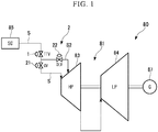
- steam turbine equipment 80 as a power generating system is provided with a steam turbine 81 including a high-pressure steam turbine 83 and a low-pressure steam turbine 84, a boiler 85 that supplies high-pressure steam to the high-pressure steam turbine 83, and a power generator 87 that is driven by a rotation drive force of the steam turbine 81.
- Each of the high-pressure steam turbine 83 and the low-pressure steam turbine 84 includes a plurality of pressure stages that are arranged from a high-pressure side to a low-pressure side.
- a steam flow channel S through which steam from the boiler 85 flows is connected to a pressure stage in the high-pressure steam turbine 83, which is closest to the high-pressure side (inlet side).
- the steam flow channel S that connects the boiler 85 and the high-pressure steam turbine 83 to each other is provided with a main steam valve 1 (TTV) and a combination valve 2 (valve device) that is provided to be connected to the main steam valve 1 in series. It is possible to select whether steam is supplied to the high-pressure steam turbine 83 or not (opening and closing state of steam flow channel S) by opening or closing the main steam valve 1.
- TTV main steam valve 1
- combination valve 2 valve device
- the combination valve 2 includes a regulating valve 21 and an overload valve 22 as main components.
- the overload valve 22 is provided on a branch flow channel S2 that branches off from the steam flow channel S at a position between the main steam valve 1 and the regulating valve 21.
- a downstream side end portion of the branch flow channel S2 is connected to a second or subsequent pressure stage (pressure stage on high-pressure side) in the high-pressure steam turbine 83 of the steam turbine 81.
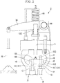
- FIG. 2 is a view showing a configuration of the combination valve 2 according to the present embodiment.
- the combination valve 2 is provided with the regulating valve 21, the overload valve 22, a valve body holder 10 (delaying and interlocking unit), a valve rod 11, an arm 30, and a hydraulic cylinder 20.
- the regulating valve 21 includes a first valve seat 12 that is exposed in the steam flow channel S and a first valve body 13 that abuts or is separated from the first valve seat 12.
- the overload valve 22 includes a second valve seat 14 that is exposed in the branch flow channel S2 and a second valve body 15 that abuts or is separated from the second valve seat 14. Furthermore, both of the first valve body 13 of the regulating valve 21 and the second valve body 15 of the overload valve 22 are held by the valve body holder 10.
- the valve body holder 10 is a member that is formed to have a thick plate-like shape and in which a plurality of through-holes 16 are formed in a thickness direction thereof. The first valve body 13 and the second valve body 15 are inserted into the through-holes 16. Furthermore, the first valve body 13, the second valve body 15, and the valve body holder 10 are accommodated in the valve chamber 18 that is defined by a valve case 17.
- a through-hole 19 heat air hole 19 that penetrates the second valve body 15 in a steam flowing direction is formed.
- the through-hole 19 is open even in a state where the second valve body 15 abuts the second valve seat 14 (that is, state where overload valve 22 is closed). That is, a steam in the branch flow channel S2 flows toward the downstream side of the overload valve 22 through the through-hole 19.
- the valve rod 11 is connected to the valve body holder 10.
- the valve rod 11 moves the valve body holder 10 by reciprocating inside the valve case 17.
- One of opposite end portions of the valve rod 11 that is on a side opposite to the valve body holder 10 side is connected to the arm 30 via an arm connection portion 12C.
- the arm 30 is a rod-shaped member that can rotate around a rotation shaft 90 provided on a portion of the valve case 17.
- the arm connection portion 12C is urged in a direction from an upper side to a lower side by a coil spring 40.
- An urging force generated by the coil spring 40 is transmitted to each of the valve body holder 10, the first valve body 13, and the second valve body 15 via the valve rod 11. Accordingly, in a state where no drive force is applied to the arm 30, the first valve body 13 abuts the first valve seat 12, the second valve body 15 abuts the second valve seat 14, and each of the regulating valve 21 and the overload valve 22 is closed.
- a rod of the hydraulic cylinder 20 (driving unit) is connected to one of opposite end portions of the arm 30 that is on a side opposite to the rotation shaft 90 side.
- the hydraulic cylinder 20 causes the rod to reciprocate by means of hydraulic pressure.
- an end portion of the arm 30 rotates around the rotation shaft 90. Accordingly, the valve rod 11 is lifted up, and the first valve body 13 and the second valve body 15 are separated from the first valve seat 12 and the second valve seat 14, respectively. That is, the regulating valve 21 and the overload valve 22 are opened.
- the first valve body 13 includes an approximately disc-shaped first valve main body 131 that abuts or is separated from the first valve seat 12, a first insert portion 132 that extends from the first valve main body 131 to form a rod-like shape and is inserted into the valve body holder 10, and a first cap portion 133 provided on an end portion of the first insert portion 132 that is on a side opposite to the first valve main body 131 side.
- the second valve body 15 includes a second valve main body 151, a second insert portion 152, and a second cap portion 153.
- the second valve main body 151 is formed such that the sizes thereof are slightly greater than those of the first valve main body 131.
- a height of the second insert portion 152 in a vertical direction is set to be larger than that of the first insert portion 132.
- the second valve body 15 is not separated from the second valve seat 14 since the valve body holder 10 only slides upward along the second insert portion 152. That is, even when the first valve body 13 is in a fully-opened state, the second valve body 15 does not enter an opened state immediately.
- the second valve body 15 is configured to be interlocked while being delayed with respect to the first valve body 13. Therefore, it is possible to cause the overload valve 22 to be opened after the regulating valve 21 enters a fully-opened state.
- the branch flow channel S2 is provided only in a portion of the steam turbine 81 in a circumferential direction. Therefore, steam supplied from the branch flow channel S2 may be unevenly distributed in the circumferential direction of the steam turbine 81.
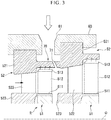
- FIG. 3 is a view showing only one pair of pressure stages facing each other in the steam turbine 81.
- the steam turbine 81 includes a rotor R that rotates around an axis O, a plurality of blades 51 that are arranged at intervals in the circumferential direction along an outer circumferential surface of the rotor R, a casing 60 that surrounds the rotor R from an outer circumferential side, a plurality of vanes 52 that are arranged at intervals in the circumferential direction along an inner circumferential surface of the casing 60, and the flow guide 70 that is attached between the vanes 52 in a direction along the axis O.
- Each vane 52 includes an outer ring 521 that is formed to have an annular shape extending along the inner circumference of the casing 60 with respect to the inner circumferential surface of the casing 60, a vane main body 522 that is attached to an inner side of the outer ring 521 in a radial direction extending from the axis O, and an inner ring 523 that is attached to an inner side of the vane main body 522 in the radial direction.
- Each blade 51 includes a platform 511 that is attached onto the outer circumferential surface of the rotor R, a blade main body 512 that is attached to an outer side of the platform 511 in the radial direction extending from the axis O, and an outer shroud 513 that is attached to an outer side of the blade main body 512 in the radial direction.
- the above-described pressure stage is configured to include the plurality of vanes 52 that are arranged at intervals in the circumferential direction on the inner circumferential surface of the casing 60 of the steam turbine 81 and the plurality of blades 51 that are disposed on the downstream side of the row of vanes 52.
- the flow guide 70 (guide main body) is provided on the downstream side of the outer ring 521.
- the flow guide 70 is a member that connects a downstream side end portion of the outer ring 521 and an upstream side end portion of another outer ring 521, which are adjacent to each other in the direction along the axis O, and has an annular shape extending in the circumferential direction of the axis O.
- a slit 71 that extends in the circumferential direction of the axis O and that is penetrated from a radially outer side to a radially inner side is formed. As seen from the circumferential direction of the axis O, the slit 71 is inclined such that the slit 71 becomes closer to the downstream side and becomes distant from the upstream side toward the radially inner side from the radially outer side.
- an overload steam inlet 61 that communicates with the above-described branch flow channel S2 is formed. That is, steam is supplied to a middle pressure stage of the steam turbine 81 through the overload steam inlet 61.
- the second valve body 15 of the overload valve 22 can enter an opened state later than the first valve body 13 of the regulating valve 21. Therefore, it is possible to open the overload valve 22 after the openness of the regulating valve 21 reaches 100% such that a load of the steam turbine 81 is further increased.
- the regulating valve 21 and the overload valve 22 are driven by the single hydraulic cylinder 20, which is the common driving source. Furthermore, it is possible to delay and interlock the regulating valve 21 and the overload valve 22 with each other only by providing the valve body holder 10 as a delaying and interlocking unit. That is, it is possible to greatly simplify the configuration of the device and thus it is possible to considerably reduce manufacturing cost and maintenance cost.
- the flow guide 70 in which the slit 71 is formed, is provided on the downstream side of the overload steam inlet 61. Therefore, it is possible to cause steam, which proceeds to an inner circumferential side of the steam turbine 81 from an outer circumferential side of the steam turbine 81, to temporarily stay near an outer circumferential side of the slit 71. Thereafter, the steam is uniformized in the circumferential direction and flows toward an inner circumferential side of the slit 71. That is, it is possible to reduce uneven distribution of steam in the circumferential direction in the steam turbine 81.
- the valve case 17 for the regulating valve 21 and the valve case 17 for the overload valve 22 are different from each other. That is, the regulating valve 21 includes the first valve body 13, the first valve seat 12, and a first valve case 17A.
- the overload valve 22 includes the second valve body 15, the second valve seat 14, and a second valve case 17B. Furthermore, a second valve rod 11B is attached to the second valve body 15. As shown in FIG. 4 , an end portion of the second valve rod 11B (end portion on side opposite to side on which second valve body 15 is provided) is exposed outside the overload valve 22.
- the first valve case 17A is provided with two arms 30 (first arm 121 and second arm 122) that extend from the rotation shaft 90 in two different directions.
- An end portion of the first arm 121 (end portion on side opposite to rotation shaft 90 side) is connected to the rod of the above-described hydraulic cylinder 20.
- the second arm 122 (delaying and interlocking unit) is a rod-shaped member that extends in a downward direction further than the first arm 121.
- the second arm 122 is integrally provided with the first arm 121. That is, when the first arm 121 rotates around the rotation shaft 90, the second arm 122 rotates around the rotation shaft 90 in accordance with the rotation of the first arm 121.
- An end portion of the second arm 122 (end portion on side opposite to rotation shaft 90 side) is rotatably connected to an upper end portion of the second valve rod 11B to which the second valve body 15 is attached. Note that, the second valve rod 11B is urged in a direction from an upper side to a lower side by a coil spring 40B as with the first valve body 13 described above.
- a slot H1 is formed in an upper end portion of the second valve rod 11B.
- the slot HI is a hole formed into a long circular shape that is elongated in a direction in which the second valve rod 11B extends.
- An end portion of the second valve rod 11B is connected to the slot HI via a pin P.
- the pin P can freely move in the vertical direction inside the slot HI.
- the first arm 121 rotates around the rotation shaft 90 in an upward direction and the first valve body 13 is separated from the first valve seat 12. Accordingly, the regulating valve 21 is opened.
- the second arm 122 also rotates around the rotation shaft 90 but only the pin P that connects the second arm 122 and the second valve rod 11B slides upward along the slot HI formed in the second valve rod 11B. Therefore, in this stage, the second valve rod 11B does not move upward. That is, the overload valve 22 is in a closed state.
- the second valve body 15 of the overload valve 22 can enter an opened state later than the first valve body 13 of the regulating valve 21. Therefore, it is possible to open the overload valve 22 after the openness of the regulating valve 21 reaches 100% such that a load of the steam turbine 81 is further increased.
- the regulating valve 21 and the overload valve 22 are driven by the single hydraulic cylinder 20, which is the common driving source. Furthermore, it is possible to interlock the regulating valve 21 and the overload valve 22 with each other only by providing the slot HI in the second valve rod 11B. That is, it is possible to greatly simplify the configuration of the device and thus it is possible to considerably reduce manufacturing cost and maintenance cost.
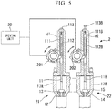
- the combination valve 2 in the present embodiment is configured by connecting the regulating valve 21 as an independent valve and the overload valve 22 to each other.
- the regulating valve 21 includes the first valve seat 12, the first valve body 13, a first valve rod 11 (valve rod 11), and a first lever 201.
- an approximately cylindrical sleeve 111 is attached to an upper portion of the first valve rod 11.
- a cavity is formed in a region close to an inner circumference of the sleeve 111.
- an approximately rod-shaped spindle 112 that is connected to the first lever 201 and that moves upward and downward integrally with the first lever 201 is provided.
- a lower end portion of the spindle 112 is connected to the first lever 201. That is, the spindle 112 moves upward and downward inside the region close to the inner circumference of the sleeve 111 in accordance with the rotation of the first lever 201.
- a hole into which an adjusting bolt 113 is inserted is formed in an upper end side of the sleeve 111.
- a portion of a shaft portion of the adjusting bolt 113 is exposed toward a region inside the sleeve 111.
- a gap d1 is formed between a lower end portion of the adjusting bolt 113 and an upper end portion of the spindle 112. A length of the gap d1 can be changed by adjusting the screwing amount of the adjusting bolt 113.
- the overload valve 22 includes the second valve seat 14, the second valve body 15, the second valve rod 11B, and a second lever 202.
- An approximately cylindrical sleeve 111B is attached to an upper portion of the second valve rod 11B.
- a cavity is formed in a region close to an inner circumference of the sleeve 111B.
- an approximately rod-shaped spindle 112B that is connected to the second lever 202 and that moves upward and downward integrally with the second lever 202 is provided.
- a lower end portion of the spindle 112B is connected to the second lever 202. That is, the spindle 112B moves upward and downward inside the region close to the inner circumference of the sleeve 111B in accordance with the rotation of the second lever 202.
- a hole into which an adjusting bolt 113B is inserted is formed in an upper end side of the sleeve 111B.
- a portion of a shaft portion of the adjusting bolt 113B is exposed toward a region inside the sleeve 111B.
- a gap d2 is formed between a lower end portion of the adjusting bolt 113B and an upper end portion of the spindle 112B. A length of the gap d2 can be changed by adjusting the screwing amount of the adjusting bolt 113B.
- the first lever 201 and the second lever 202 are connected to the first valve rod 11 and the second valve rod 11B respectively and are rotated by a single driving unit such as the hydraulic cylinder 20.
- the first valve rod 11 and the second valve rod 11B reciprocate in the vertical direction in accordance with the rotation of the first lever 201 and the second lever 202. More specifically, when the first lever 201 moves upward, first the spindle 112 moves upward. At this time, the spindle 112 abuts the shaft portion of the adjusting bolt 113 after moving upward by a distance in the vertical direction of the gap d1.
- the spindle 112B moves upward by a distance corresponding to the gap d2 and abuts the shaft portion of the adjusting bolt 113B.
- the spindle 112B lifts up the sleeve 111B and the second valve rod 11B via the adjusting bolt 113B. Therefore, the overload valve 22 enters an opened state.
- the gap d2 in the overload valve 22 is set to be larger than the gap d1 in the regulating valve 21. Therefore, when the first lever 201 and the second lever 202 are rotated by the same amount at the same time, the second valve body 15 of the overload valve 22 enters an opened state later than the first valve body 13 of the regulating valve 21 corresponding to a difference between the gap d2 and the gap d1.
- the second valve body 15 of the overload valve 22 can enter an opened state later than the first valve body 13 of the regulating valve 21. Therefore, it is possible to open the overload valve 22 after the openness of the regulating valve 21 reaches 100% such that a load of the steam turbine 81 is further increased.
- the regulating valve 21 and the overload valve 22 are driven by the single hydraulic cylinder 20, which is the common driving source.
- the regulating valve 21 and the overload valve 22 are not limited to this.
- the regulating valve 21 may be configured to be provided with a plurality of first valve seats 12 and a plurality of first valve bodies 13 that abut or are separated from each other.
- the overload valve 22 may be configured to be provided with a plurality of second valve seats 14 and a plurality of second valve bodies 15 that abut onto or are separated from each other.
- a configuration in which the regulating valve 21 is provided with a plurality of first valve seats 12 and a plurality of first valve bodies 13 and the overload valve 22 is provided with a plurality of second valve seats 14 and a plurality of second valve bodies 15 may also be adopted.
Landscapes
- Engineering & Computer Science (AREA)
- General Engineering & Computer Science (AREA)
- Mechanical Engineering (AREA)
- Control Of Turbines (AREA)
- Mechanically-Actuated Valves (AREA)
- Lift Valve (AREA)
Abstract
Description
- The present invention relates to a valve device and a steam turbine equipment.
- A steam turbine is used for the purpose of driving a machine or the like and is provided with a turbine main body that includes a rotatably supported rotor. The rotor is driven to be rotated when steam is supplied to the turbine main body as working fluid. Steam to be supplied to the turbine main body or steam extracted from the turbine main body flows in a steam flow channel of the steam turbine. The steam flow channel is provided with a regulating valve. It is possible to adjust the flow rate of steam to be supplied to the turbine main body by adjusting the openness of the regulating valve.
- Furthermore, a steam turbine that is provided with an overload valve in addition to the above-described regulating valve is also known (refer to
Patent Document 1 below). In steam turbine equipment described inPatent Document 1, an overload valve is provided on a bypass pipe that branches off from a main steam pipe. It is possible to supply main steam to a middle stage of a high-pressure turbine by opening the overload valve. -
Patent Document 1 United States Patent Application, Publication No.2015/0020527 - However, in the case of a technology described in
Patent Document 1 above, there is a possibility that it is difficult to synchronize the regulating valve and the overload valve. Furthermore, in a case where the regulating valve and the overload valve are opened or closed individually, pressure loss in these valve devices becomes great and thus there is a possibility that the efficiency of the steam turbine is influenced. - The present invention has been made in consideration of the above-described circumstances and an object thereof is to provide a valve device and steam turbine equipment having a simple configuration and a sufficient efficiency.
- The invention adopts the following means to solve the above-described problems.
- According to a first aspect of the invention, a valve device includes a main steam valve that is provided on a steam flow channel which guides steam to a steam turbine and that adjusts an opening and closing state of the steam flow channel, a regulating valve that is provided on the steam flow channel to be connected to the main steam valve in series and that includes a first valve seat which is exposed in the steam flow channel and a first valve body which abuts or is separated from the first valve seat to adjust a flowing state in the steam flow channel, an overload valve that is provided on a branch flow channel which connects a portion of the steam flow channel between the main steam valve and the regulating valve and the steam turbine to each other and that includes a second valve seat which is exposed in the branch flow channel and a second valve body which abuts or is separated from the second valve seat to adjust a flowing state in the branch flow channel, and a driving unit that drives the first valve body and the second valve body as a common driving source of the first valve body and the second valve body such that the first valve body and the second valve body are interlocked with each other.
- According to the above-described configuration, the first valve body and the second valve body can be interlocked by means of the driving unit, which is the common driving source. Therefore, it is possible to simplify the configuration of a device.
- According to a second aspect of the invention, the valve device in the first aspect may further include a delaying and interlocking unit that delays the driving of the second valve body of the overload valve until the regulating valve enters a fully-opened state with the first valve body being driven.
- According to the above-described configuration, the driving of the overload valve is delayed by the delaying and interlocking unit until the regulating valve enters the fully-opened state. Therefore, it is possible to operate the device in on overload state.
- According to a third aspect of the invention, in the valve device in the first or second aspect, the steam turbine may include a plurality of pressure stages that are arranged from a high-pressure side to a low-pressure side, the steam flow channel may be connected to a pressure stage in the steam turbine, which is closest to the high-pressure side, and the branch flow channel may be connected to a second or subsequent pressure stage in the steam turbine.
- According to the above-described configuration, since the branch flow channel is connected to the pressure stage in the steam turbine, which is closest to the high-pressure side, it is possible to further improve the output of the steam turbine by supplying steam from the branch flow channel as well in addition to a supplying amount from the steam flow channel. That is, it is possible to operate the steam turbine in an overload state.
- According to a fourth aspect of the invention, the valve device in the third aspect may further include a flow guide that is provided between the overload valve and the pressure stages and that changes a flowing direction of steam passing through the overload valve.
- According to the above-described configuration, since the flow guide is provided, the flowing direction of steam passing through the overload valve can be changed. That is, it is possible to reduce a possibility of uneven distribution of steam in the pressure stages of the steam turbine.
- According to a fifth aspect of the invention, in the valve device in the fourth aspect, the flow guide may include a guide main body that extends in a circumferential direction of the steam turbine and a slit that extends from an outer circumferential side of the steam turbine to an inner circumferential side of the steam turbine toward the low-pressure side from the high-pressure side may be formed in the guide main body.
- According to the above-described configuration, since the slit is provided, it is possible to cause steam, which proceeds to the inner circumferential side of the steam turbine from the outer circumferential side of the steam turbine, to temporarily stay near an outer circumferential side of the slit. Thereafter, the steam is uniformized in the circumferential direction and flows toward an inner circumferential side of the slit. Accordingly, it is possible to reduce uneven distribution of steam in the circumferential direction in the steam turbine.
- According to a sixth aspect of the invention, in the valve device according to any one of the first to fifth aspects, a through-hole through which a portion of steam in the branch flow channel flows may be formed in the second valve body of the overload valve.
- According to the above-described configuration, even in a state where the overload valve is closed, steam is supplied from the inside of the branch flow channel to the inside of the steam turbine through the through-hole of the second valve body. It is possible to preheat the inside of the steam turbine with the steam.
- According to a seventh aspect of the invention, a steam turbine equipment includes the valve device according to any one of the first to sixth aspects and a steam turbine that is driven by steam guided through the valve device.
- According to the above-described configuration, it is possible to provide a steam turbine having a simple configuration and a sufficient efficiency.
- According to the invention, it is possible to provide a valve device and a steam turbine having a simple configuration and a sufficient efficiency.
-
-
FIG. 1 is a schematic view showing a configuration of steam turbine equipment according to a first embodiment of the invention. -
FIG. 2 is a sectional view showing a configuration of a valve device according to the first embodiment of the invention. -
FIG. 3 is a sectional view showing a main portion of the steam turbine equipment according to the first embodiment of the invention. -
FIG. 4 is a schematic view showing a configuration of a valve device according to a second embodiment of the invention. -
FIG. 5 is a schematic view showing a configuration of a valve device according to a third embodiment of the invention. - A first embodiment of the invention will be described with reference to drawings. As shown in
FIG. 1 ,steam turbine equipment 80 as a power generating system according to the present embodiment is provided with asteam turbine 81 including a high-pressure steam turbine 83 and a low-pressure steam turbine 84, aboiler 85 that supplies high-pressure steam to the high-pressure steam turbine 83, and apower generator 87 that is driven by a rotation drive force of thesteam turbine 81. - Each of the high-
pressure steam turbine 83 and the low-pressure steam turbine 84 includes a plurality of pressure stages that are arranged from a high-pressure side to a low-pressure side. Among these, a steam flow channel S through which steam from theboiler 85 flows is connected to a pressure stage in the high-pressure steam turbine 83, which is closest to the high-pressure side (inlet side). - The steam flow channel S that connects the
boiler 85 and the high-pressure steam turbine 83 to each other is provided with a main steam valve 1 (TTV) and a combination valve 2 (valve device) that is provided to be connected to themain steam valve 1 in series. It is possible to select whether steam is supplied to the high-pressure steam turbine 83 or not (opening and closing state of steam flow channel S) by opening or closing themain steam valve 1. - The
combination valve 2 includes a regulatingvalve 21 and anoverload valve 22 as main components. When the openness of the regulatingvalve 21 is adjusted, the flowing state of steam to the high-pressure steam turbine 83 is adjusted. Theoverload valve 22 is provided on a branch flow channel S2 that branches off from the steam flow channel S at a position between themain steam valve 1 and the regulatingvalve 21. A downstream side end portion of the branch flow channel S2 is connected to a second or subsequent pressure stage (pressure stage on high-pressure side) in the high-pressure steam turbine 83 of thesteam turbine 81. -
FIG. 2 is a view showing a configuration of thecombination valve 2 according to the present embodiment. As shown in the drawing, in thecombination valve 2, the regulatingvalve 21 and theoverload valve 22 are accommodated in the same valve chamber 18. More specifically, thecombination valve 2 is provided with the regulatingvalve 21, theoverload valve 22, a valve body holder 10 (delaying and interlocking unit), avalve rod 11, anarm 30, and ahydraulic cylinder 20. - The regulating
valve 21 includes afirst valve seat 12 that is exposed in the steam flow channel S and afirst valve body 13 that abuts or is separated from thefirst valve seat 12. Theoverload valve 22 includes asecond valve seat 14 that is exposed in the branch flow channel S2 and asecond valve body 15 that abuts or is separated from thesecond valve seat 14. Furthermore, both of thefirst valve body 13 of the regulatingvalve 21 and thesecond valve body 15 of theoverload valve 22 are held by the valve body holder 10. The valve body holder 10 is a member that is formed to have a thick plate-like shape and in which a plurality of through-holes 16 are formed in a thickness direction thereof. Thefirst valve body 13 and thesecond valve body 15 are inserted into the through-holes 16. Furthermore, thefirst valve body 13, thesecond valve body 15, and the valve body holder 10 are accommodated in the valve chamber 18 that is defined by avalve case 17. - Note that, in the
second valve body 15, a through-hole 19 (heat air hole 19) that penetrates thesecond valve body 15 in a steam flowing direction is formed. The through-hole 19 is open even in a state where thesecond valve body 15 abuts the second valve seat 14 (that is, state whereoverload valve 22 is closed). That is, a steam in the branch flow channel S2 flows toward the downstream side of theoverload valve 22 through the through-hole 19. - The
valve rod 11 is connected to the valve body holder 10. Thevalve rod 11 moves the valve body holder 10 by reciprocating inside thevalve case 17. One of opposite end portions of thevalve rod 11 that is on a side opposite to the valve body holder 10 side is connected to thearm 30 via anarm connection portion 12C. Thearm 30 is a rod-shaped member that can rotate around arotation shaft 90 provided on a portion of thevalve case 17. Furthermore, thearm connection portion 12C is urged in a direction from an upper side to a lower side by acoil spring 40. An urging force generated by thecoil spring 40 is transmitted to each of the valve body holder 10, thefirst valve body 13, and thesecond valve body 15 via thevalve rod 11. Accordingly, in a state where no drive force is applied to thearm 30, thefirst valve body 13 abuts thefirst valve seat 12, thesecond valve body 15 abuts thesecond valve seat 14, and each of the regulatingvalve 21 and theoverload valve 22 is closed. - Furthermore, a rod of the hydraulic cylinder 20 (driving unit) is connected to one of opposite end portions of the
arm 30 that is on a side opposite to therotation shaft 90 side. Thehydraulic cylinder 20 causes the rod to reciprocate by means of hydraulic pressure. When the rod reciprocates, an end portion of thearm 30 rotates around therotation shaft 90. Accordingly, thevalve rod 11 is lifted up, and thefirst valve body 13 and thesecond valve body 15 are separated from thefirst valve seat 12 and thesecond valve seat 14, respectively. That is, the regulatingvalve 21 and theoverload valve 22 are opened. - Here, the configurations of the
first valve body 13 and thesecond valve body 15 will be described in detail. Thefirst valve body 13 includes an approximately disc-shaped first valvemain body 131 that abuts or is separated from thefirst valve seat 12, afirst insert portion 132 that extends from the first valvemain body 131 to form a rod-like shape and is inserted into the valve body holder 10, and afirst cap portion 133 provided on an end portion of thefirst insert portion 132 that is on a side opposite to the first valvemain body 131 side. Similarly, thesecond valve body 15 includes a second valvemain body 151, asecond insert portion 152, and asecond cap portion 153. Here, the second valvemain body 151 is formed such that the sizes thereof are slightly greater than those of the first valvemain body 131. Furthermore, a height of thesecond insert portion 152 in a vertical direction is set to be larger than that of thefirst insert portion 132. - Therefore, in a case where the valve body holder 10 is lifted up with the
hydraulic cylinder 20 being driven, thefirst valve body 13 is immediately lifted up. On thesecond valve body 15 side, thesecond valve body 15 is not separated from thesecond valve seat 14 since the valve body holder 10 only slides upward along thesecond insert portion 152. That is, even when thefirst valve body 13 is in a fully-opened state, thesecond valve body 15 does not enter an opened state immediately. In other words, thesecond valve body 15 is configured to be interlocked while being delayed with respect to thefirst valve body 13. Therefore, it is possible to cause theoverload valve 22 to be opened after the regulatingvalve 21 enters a fully-opened state. - Steam that is supplied with the
overload valve 22 being opened as described above is supplied to a second or subsequent pressure stage of the steam turbine 81 (high-pressure steam turbine 83) through the branch flow channel S2. Here, the branch flow channel S2 is provided only in a portion of thesteam turbine 81 in a circumferential direction. Therefore, steam supplied from the branch flow channel S2 may be unevenly distributed in the circumferential direction of thesteam turbine 81. - Therefore, in the steam turbine 81 (high-pressure steam turbine 83) according to the present embodiment, a
flow guide 70 for changing the flow of steam is provided as shown inFIG. 3. FIG. 3 is a view showing only one pair of pressure stages facing each other in thesteam turbine 81. Thesteam turbine 81 includes a rotor R that rotates around an axis O, a plurality ofblades 51 that are arranged at intervals in the circumferential direction along an outer circumferential surface of the rotor R, acasing 60 that surrounds the rotor R from an outer circumferential side, a plurality ofvanes 52 that are arranged at intervals in the circumferential direction along an inner circumferential surface of thecasing 60, and theflow guide 70 that is attached between thevanes 52 in a direction along the axis O. - Each
vane 52 includes anouter ring 521 that is formed to have an annular shape extending along the inner circumference of thecasing 60 with respect to the inner circumferential surface of thecasing 60, a vanemain body 522 that is attached to an inner side of theouter ring 521 in a radial direction extending from the axis O, and aninner ring 523 that is attached to an inner side of the vanemain body 522 in the radial direction. - Each
blade 51 includes aplatform 511 that is attached onto the outer circumferential surface of the rotor R, a blademain body 512 that is attached to an outer side of theplatform 511 in the radial direction extending from the axis O, and anouter shroud 513 that is attached to an outer side of the blademain body 512 in the radial direction. - The above-described pressure stage is configured to include the plurality of
vanes 52 that are arranged at intervals in the circumferential direction on the inner circumferential surface of thecasing 60 of thesteam turbine 81 and the plurality ofblades 51 that are disposed on the downstream side of the row ofvanes 52. On the downstream side of theouter ring 521, the flow guide 70 (guide main body) is provided. The flow guide 70 is a member that connects a downstream side end portion of theouter ring 521 and an upstream side end portion of anotherouter ring 521, which are adjacent to each other in the direction along the axis O, and has an annular shape extending in the circumferential direction of the axis O. - In the
flow guide 70, aslit 71 that extends in the circumferential direction of the axis O and that is penetrated from a radially outer side to a radially inner side is formed. As seen from the circumferential direction of the axis O, theslit 71 is inclined such that theslit 71 becomes closer to the downstream side and becomes distant from the upstream side toward the radially inner side from the radially outer side. - Furthermore, as seen from the
flow guide 70, in thecasing 60 that is positioned radially outward of the axis O, anoverload steam inlet 61 that communicates with the above-described branch flow channel S2 is formed. That is, steam is supplied to a middle pressure stage of thesteam turbine 81 through theoverload steam inlet 61. - According to the above-described configuration, the
second valve body 15 of theoverload valve 22 can enter an opened state later than thefirst valve body 13 of the regulatingvalve 21. Therefore, it is possible to open theoverload valve 22 after the openness of the regulatingvalve 21 reaches 100% such that a load of thesteam turbine 81 is further increased. - In addition, in the above-described configuration, the regulating
valve 21 and theoverload valve 22 are driven by the singlehydraulic cylinder 20, which is the common driving source. Furthermore, it is possible to delay and interlock the regulatingvalve 21 and theoverload valve 22 with each other only by providing the valve body holder 10 as a delaying and interlocking unit. That is, it is possible to greatly simplify the configuration of the device and thus it is possible to considerably reduce manufacturing cost and maintenance cost. - Furthermore, according to the above-described configuration, on the downstream side of the
overload steam inlet 61, theflow guide 70, in which theslit 71 is formed, is provided. Therefore, it is possible to cause steam, which proceeds to an inner circumferential side of thesteam turbine 81 from an outer circumferential side of thesteam turbine 81, to temporarily stay near an outer circumferential side of theslit 71. Thereafter, the steam is uniformized in the circumferential direction and flows toward an inner circumferential side of theslit 71. That is, it is possible to reduce uneven distribution of steam in the circumferential direction in thesteam turbine 81. - Furthermore, according to the above-described configuration, even in a state where the
overload valve 22 is closed, steam is supplied from the inside of the branch flow channel S2 to the inside of thesteam turbine 81 through the through-hole 19 of thesecond valve body 15. It is possible to preheat the inside of thesteam turbine 81 with the steam. - Next, a second embodiment of the invention will be described with reference to
FIG. 4 . - In the
combination valve 2 according to the present embodiment, unlike in the first embodiment, thevalve case 17 for the regulatingvalve 21 and thevalve case 17 for theoverload valve 22 are different from each other. That is, the regulatingvalve 21 includes thefirst valve body 13, thefirst valve seat 12, and afirst valve case 17A. Theoverload valve 22 includes thesecond valve body 15, thesecond valve seat 14, and asecond valve case 17B. Furthermore, asecond valve rod 11B is attached to thesecond valve body 15. As shown inFIG. 4 , an end portion of thesecond valve rod 11B (end portion on side opposite to side on whichsecond valve body 15 is provided) is exposed outside theoverload valve 22. - Furthermore, the
first valve case 17A is provided with two arms 30 (first arm 121 and second arm 122) that extend from therotation shaft 90 in two different directions. An end portion of the first arm 121 (end portion on side opposite torotation shaft 90 side) is connected to the rod of the above-describedhydraulic cylinder 20. When thefirst arm 121 rotates around therotation shaft 90 in accordance with reciprocating motion of the rod, thefirst valve body 13 of the regulatingvalve 21 moves upward and downward in the same manner as in the first embodiment. - As seen from the
rotation shaft 90, the second arm 122 (delaying and interlocking unit) is a rod-shaped member that extends in a downward direction further than thefirst arm 121. Thesecond arm 122 is integrally provided with thefirst arm 121. That is, when thefirst arm 121 rotates around therotation shaft 90, thesecond arm 122 rotates around therotation shaft 90 in accordance with the rotation of thefirst arm 121. An end portion of the second arm 122 (end portion on side opposite torotation shaft 90 side) is rotatably connected to an upper end portion of thesecond valve rod 11B to which thesecond valve body 15 is attached. Note that, thesecond valve rod 11B is urged in a direction from an upper side to a lower side by acoil spring 40B as with thefirst valve body 13 described above. - Furthermore, a slot H1 is formed in an upper end portion of the
second valve rod 11B. The slot HI is a hole formed into a long circular shape that is elongated in a direction in which thesecond valve rod 11B extends. An end portion of thesecond valve rod 11B is connected to the slot HI via a pin P. The pin P can freely move in the vertical direction inside the slot HI. - According to the above-described configuration, in a case where the
hydraulic cylinder 20 is driven to open the regulatingvalve 21 first, thefirst arm 121 rotates around therotation shaft 90 in an upward direction and thefirst valve body 13 is separated from thefirst valve seat 12. Accordingly, the regulatingvalve 21 is opened. At this time, thesecond arm 122 also rotates around therotation shaft 90 but only the pin P that connects thesecond arm 122 and thesecond valve rod 11B slides upward along the slot HI formed in thesecond valve rod 11B. Therefore, in this stage, thesecond valve rod 11B does not move upward. That is, theoverload valve 22 is in a closed state. - In a case where the
first arm 121 is further rotated upward in the above-described state, that is, in a case where thefirst arm 121 and thesecond arm 122 are rotated until the pin P reaches an upper end portion of the slot HI, thesecond valve rod 11B and thesecond valve body 15 are lifted up and theoverload valve 22 is opened. - According to the above-described configuration as well, as with the first embodiment, the
second valve body 15 of theoverload valve 22 can enter an opened state later than thefirst valve body 13 of the regulatingvalve 21. Therefore, it is possible to open theoverload valve 22 after the openness of the regulatingvalve 21 reaches 100% such that a load of thesteam turbine 81 is further increased. - In addition, in the above-described configuration as well, the regulating
valve 21 and theoverload valve 22 are driven by the singlehydraulic cylinder 20, which is the common driving source. Furthermore, it is possible to interlock the regulatingvalve 21 and theoverload valve 22 with each other only by providing the slot HI in thesecond valve rod 11B. That is, it is possible to greatly simplify the configuration of the device and thus it is possible to considerably reduce manufacturing cost and maintenance cost. - Next, a third embodiment of the invention will be described with reference to
FIG. 5 . As shown in the drawing, thecombination valve 2 in the present embodiment is configured by connecting the regulatingvalve 21 as an independent valve and theoverload valve 22 to each other. The regulatingvalve 21 includes thefirst valve seat 12, thefirst valve body 13, a first valve rod 11 (valve rod 11), and afirst lever 201. - Furthermore, an approximately
cylindrical sleeve 111 is attached to an upper portion of thefirst valve rod 11. A cavity is formed in a region close to an inner circumference of thesleeve 111. In the cavity, an approximately rod-shapedspindle 112 that is connected to thefirst lever 201 and that moves upward and downward integrally with thefirst lever 201 is provided. Specifically, a lower end portion of thespindle 112 is connected to thefirst lever 201. That is, thespindle 112 moves upward and downward inside the region close to the inner circumference of thesleeve 111 in accordance with the rotation of thefirst lever 201. - A hole into which an
adjusting bolt 113 is inserted is formed in an upper end side of thesleeve 111. A portion of a shaft portion of the adjustingbolt 113 is exposed toward a region inside thesleeve 111. Furthermore, a gap d1 is formed between a lower end portion of the adjustingbolt 113 and an upper end portion of thespindle 112. A length of the gap d1 can be changed by adjusting the screwing amount of the adjustingbolt 113. - Similarly, the
overload valve 22 includes thesecond valve seat 14, thesecond valve body 15, thesecond valve rod 11B, and asecond lever 202. An approximatelycylindrical sleeve 111B is attached to an upper portion of thesecond valve rod 11B. A cavity is formed in a region close to an inner circumference of thesleeve 111B. In the cavity, an approximately rod-shapedspindle 112B that is connected to thesecond lever 202 and that moves upward and downward integrally with thesecond lever 202 is provided. Specifically, a lower end portion of thespindle 112B is connected to thesecond lever 202. That is, thespindle 112B moves upward and downward inside the region close to the inner circumference of thesleeve 111B in accordance with the rotation of thesecond lever 202. - In an upper end side of the
sleeve 111B, a hole into which anadjusting bolt 113B is inserted is formed. A portion of a shaft portion of the adjustingbolt 113B is exposed toward a region inside thesleeve 111B. Furthermore, a gap d2 is formed between a lower end portion of the adjustingbolt 113B and an upper end portion of thespindle 112B. A length of the gap d2 can be changed by adjusting the screwing amount of the adjustingbolt 113B. - Note that, in the present embodiment, an example in which the length of the gap d2 in the
overload valve 22 is set to be larger than the length of the gap d1 in the regulatingvalve 21 will be described. - The
first lever 201 and thesecond lever 202 are connected to thefirst valve rod 11 and thesecond valve rod 11B respectively and are rotated by a single driving unit such as thehydraulic cylinder 20. Thefirst valve rod 11 and thesecond valve rod 11B reciprocate in the vertical direction in accordance with the rotation of thefirst lever 201 and thesecond lever 202. More specifically, when thefirst lever 201 moves upward, first thespindle 112 moves upward. At this time, thespindle 112 abuts the shaft portion of the adjustingbolt 113 after moving upward by a distance in the vertical direction of the gap d1. When thefirst lever 201 moves upward after thespindle 112 abuts the shaft portion of the adjustingbolt 113, thespindle 112 lifts up thesleeve 111 and thefirst valve rod 11 via the adjustingbolt 113. Therefore, the regulatingvalve 21 enters an opened state. - Similarly, in the
overload valve 22 as well, when thesecond lever 202 moves upward, thespindle 112B moves upward by a distance corresponding to the gap d2 and abuts the shaft portion of the adjustingbolt 113B. When thesecond lever 202 moves upward after thespindle 112B abuts the shaft portion of the adjustingbolt 113B, thespindle 112B lifts up thesleeve 111B and thesecond valve rod 11B via the adjustingbolt 113B. Therefore, theoverload valve 22 enters an opened state. - Here, as described above, the gap d2 in the
overload valve 22 is set to be larger than the gap d1 in the regulatingvalve 21. Therefore, when thefirst lever 201 and thesecond lever 202 are rotated by the same amount at the same time, thesecond valve body 15 of theoverload valve 22 enters an opened state later than thefirst valve body 13 of the regulatingvalve 21 corresponding to a difference between the gap d2 and the gap d1. - According to the above-described configuration as well, as with the first embodiment or the second embodiment, the
second valve body 15 of theoverload valve 22 can enter an opened state later than thefirst valve body 13 of the regulatingvalve 21. Therefore, it is possible to open theoverload valve 22 after the openness of the regulatingvalve 21 reaches 100% such that a load of thesteam turbine 81 is further increased. In addition, in the above-described configuration as well, the regulatingvalve 21 and theoverload valve 22 are driven by the singlehydraulic cylinder 20, which is the common driving source. - Hereinabove, the embodiments of the invention have been described with reference to the drawings. However, various modifications and improvements can be made with respect to the above-described configuration without departing from the gist of the invention.
- Note that, in the embodiments, a configuration in which the regulating
valve 21 is provided with onefirst valve seat 12 and onefirst valve body 13 and theoverload valve 22 is provided with onesecond valve seat 14 and onesecond valve body 15 has been described. - However, embodiments of the regulating
valve 21 and theoverload valve 22 are not limited to this. For example, the regulatingvalve 21 may be configured to be provided with a plurality of first valve seats 12 and a plurality offirst valve bodies 13 that abut or are separated from each other. Similarly, theoverload valve 22 may be configured to be provided with a plurality of second valve seats 14 and a plurality ofsecond valve bodies 15 that abut onto or are separated from each other. Furthermore, a configuration in which the regulatingvalve 21 is provided with a plurality of first valve seats 12 and a plurality offirst valve bodies 13 and theoverload valve 22 is provided with a plurality of second valve seats 14 and a plurality ofsecond valve bodies 15 may also be adopted. - According to the above-described configuration, it is possible to achieve a valve device and a steam turbine having a simple configuration and a sufficient efficiency.
- 1...main steam valve 2...combination valve 10...valve body holder 11...valve rod 30...arm 12...first valve seat 13...first valve body 14...second valve seat 15...second valve body 16...through-hole 17...valve case 18...valve chamber 19...through-hole (heat air hole) 20...hydraulic cylinder 21...regulating valve 22...overload valve 90...rotation shaft 40...coil spring 51...blade 52...vane 60...casing 61...overload steam inlet 70...flow guide 71...slit 80...steam turbine equipment 81...steam turbine 83...high-pressure steam turbine 84...low-pressure steam turbine 85...boiler 86...reheater 87...power generator 111, 111B...sleeve 112, 112B...spindle 113, 113B...adjusting bolt 121...first arm 122...second arm 131...first valve main body 132...first insert portion 133...first cap portion 151...second valve main body 152...second insert portion 153...second cap portion 201...first lever 202...second lever 511...platform 512...blade main body 513...outer shroud 521...outer ring 522...vane main body 523...inner ring 11B...second valve rod 12C...arm connection portion 40B...coil spring d1, d2...gap HI...slot H2...slot O...axis R...rotor S...steam flow channel S2...branch flow channel
Claims (7)
- A valve device comprising:a main steam valve that is provided on a steam flow channel which guides steam to a steam turbine and that adjusts an opening and closing state of the steam flow channel;a regulating valve that is provided on the steam flow channel to be connected to the main steam valve in series, and the regulating valve that includes a first valve seat which is exposed in the steam flow channel and a first valve body which abuts or is separated from the first valve seat to adjust a flowing state in the steam flow channel;an overload valve that is provided on a branch flow channel which connects a portion of the steam flow channel between the main steam valve and the regulating valve, and the steam turbine to each other, and the overload valve that includes a second valve seat which is exposed in the branch flow channel and a second valve body which abuts or is separated from the second valve seat to adjust a flowing state in the branch flow channel; anda driving unit that drives the first valve body and the second valve body as a common driving source of the first valve body and the second valve body such that the first valve body and the second valve body are interlocked with each other.
- The valve device according to claim 1, further comprising:
a delaying and interlocking unit that delays the driving of the second valve body of the overload valve until the regulating valve enters a fully-opened state. - The valve device according to claim 1 or 2,
wherein the steam turbine includes a plurality of pressure stages that are arranged from a high-pressure side to a low-pressure side,
wherein the steam flow channel is connected to a pressure stage in the steam turbine, which is closest to the high-pressure side, and
wherein the branch flow channel is connected to a second or subsequent pressure stage in the steam turbine. - The valve device according to claim 3, further comprising:
a flow guide that is provided between the overload valve and the pressure stages and that changes a flowing direction of steam passing through the overload valve. - The valve device according to claim 4,
wherein the flow guide includes a guide main body that extends in a circumferential direction of the steam turbine, and
wherein a slit that extends from an outer circumferential side of the steam turbine to an inner circumferential side of the steam turbine toward the low-pressure side from the high-pressure side is formed in the guide main body. - The valve device according to any one of claims 1 to 5,
wherein a through-hole through which a portion of steam in the branch flow channel flows is formed in the second valve body of the overload valve. - A steam turbine equipment comprising:the valve device according to any one of claims 1 to 6; anda steam turbine that is driven by steam guided through the valve device.
Applications Claiming Priority (1)
| Application Number | Priority Date | Filing Date | Title |
|---|---|---|---|
| PCT/JP2015/080387 WO2017072880A1 (en) | 2015-10-28 | 2015-10-28 | Valve device and steam turbine equipment |
Publications (3)
| Publication Number | Publication Date |
|---|---|
| EP3369976A1 true EP3369976A1 (en) | 2018-09-05 |
| EP3369976A4 EP3369976A4 (en) | 2019-06-12 |
| EP3369976B1 EP3369976B1 (en) | 2020-12-02 |
Family
ID=58629979
Family Applications (1)
| Application Number | Title | Priority Date | Filing Date |
|---|---|---|---|
| EP15907244.6A Active EP3369976B1 (en) | 2015-10-28 | 2015-10-28 | Valve device and steam turbine equipment |
Country Status (4)
| Country | Link |
|---|---|
| US (1) | US10605114B2 (en) |
| EP (1) | EP3369976B1 (en) |
| JP (1) | JP6327775B2 (en) |
| WO (1) | WO2017072880A1 (en) |
Cited By (1)
| Publication number | Priority date | Publication date | Assignee | Title |
|---|---|---|---|---|
| CN113700534A (en) * | 2021-08-31 | 2021-11-26 | 中国船舶重工集团公司第七0三研究所 | High-power ship steam turbine external bypass cylinder |
Families Citing this family (2)
| Publication number | Priority date | Publication date | Assignee | Title |
|---|---|---|---|---|
| JP7216567B2 (en) * | 2019-02-25 | 2023-02-01 | 三菱重工コンプレッサ株式会社 | valve gear and steam turbine |
| CN115899326B (en) * | 2022-11-23 | 2025-07-29 | 杭州瑞能科技设备有限公司 | Quick-closing and adjusting integrated valve for recovering waste heat of ultralow-temperature low-pressure esterification steam |
Family Cites Families (13)
| Publication number | Priority date | Publication date | Assignee | Title |
|---|---|---|---|---|
| FR401118A (en) | 1909-03-23 | 1909-08-19 | Thomson Houston Aciens Etables | Application of a voltage regulator as a speed regulator |
| DE1915267B2 (en) | 1969-03-26 | 1971-05-06 | Siemens AG, 1000 Berlin u 8000 München | INPUT BOX FOR NOZZLE GROUP CONTROL OF STEAM TURBINES |
| US4098280A (en) | 1976-10-22 | 1978-07-04 | Ristvedt Victor G | Coin handling machine |
| US4456032A (en) | 1982-01-18 | 1984-06-26 | Elliott Turbomachinery Company, Inc. | Fluid admission valve structure |
| JPS5970003U (en) | 1982-11-01 | 1984-05-12 | 三菱重工業株式会社 | steam turbine |
| JPS62236497A (en) * | 1985-09-17 | 1987-10-16 | Chugai Pharmaceut Co Ltd | Novel glycoprotein and production thereof |
| JPH0246002A (en) * | 1988-08-08 | 1990-02-15 | Nissan Motor Co Ltd | Antenna system for vehicle |
| JPH0246002U (en) | 1988-09-26 | 1990-03-29 | ||
| JP5823302B2 (en) | 2012-01-17 | 2015-11-25 | 株式会社東芝 | Steam turbine controller |
| WO2014155579A1 (en) | 2013-03-27 | 2014-10-02 | 三菱重工コンプレッサ株式会社 | Multi-valve-type steam valve and steam turbine |
| US20150020527A1 (en) | 2013-07-19 | 2015-01-22 | General Electric Company | Steam turbomachine having a bypass circuit for throttle flow capacity adjustment |
| JP6201548B2 (en) | 2013-09-09 | 2017-09-27 | 三菱日立パワーシステムズ株式会社 | Rotating machine |
| JP6285692B2 (en) * | 2013-11-05 | 2018-02-28 | 三菱日立パワーシステムズ株式会社 | Steam turbine equipment |
-
2015
- 2015-10-28 WO PCT/JP2015/080387 patent/WO2017072880A1/en not_active Ceased
- 2015-10-28 EP EP15907244.6A patent/EP3369976B1/en active Active
- 2015-10-28 JP JP2017547252A patent/JP6327775B2/en active Active
- 2015-10-28 US US15/771,064 patent/US10605114B2/en active Active
Cited By (1)
| Publication number | Priority date | Publication date | Assignee | Title |
|---|---|---|---|---|
| CN113700534A (en) * | 2021-08-31 | 2021-11-26 | 中国船舶重工集团公司第七0三研究所 | High-power ship steam turbine external bypass cylinder |
Also Published As
| Publication number | Publication date |
|---|---|
| WO2017072880A1 (en) | 2017-05-04 |
| JPWO2017072880A1 (en) | 2018-03-08 |
| US10605114B2 (en) | 2020-03-31 |
| EP3369976A4 (en) | 2019-06-12 |
| JP6327775B2 (en) | 2018-05-23 |
| US20180306050A1 (en) | 2018-10-25 |
| EP3369976B1 (en) | 2020-12-02 |
Similar Documents
| Publication | Publication Date | Title |
|---|---|---|
| US10227898B2 (en) | Multi-valve steam valve and steam turbine | |
| JP6058028B2 (en) | Steam valve and steam turbine | |
| EP2503105B1 (en) | Steam valve device and steam turbine plant | |
| US9157366B2 (en) | Adaptive fan with cold turbine | |
| EP3369976B1 (en) | Valve device and steam turbine equipment | |
| CN102171418A (en) | System for controlling variable geometry apparatuses of a gas turbine engine particularly comprising a barrel link | |
| US20180216486A1 (en) | Hydraulic driving device for steam valve, combined steam valve, and steam turbine | |
| CN207080624U (en) | The regulating valve of technique productions equipment | |
| EP3094822B1 (en) | Blade for a gas turbine and method for manufacturing said blade | |
| US20170298742A1 (en) | Turbine engine airfoil bleed pumping | |
| EP2873804A1 (en) | Steam turbine equipment | |
| US9260973B2 (en) | Fan blade adjustment piezoelectric actuator | |
| US20140219807A1 (en) | Under-root spacer for gas turbine engine fan blade | |
| JP5562250B2 (en) | HYDRAULIC DEVICE, ENERGY CONVERSION EQUIPMENT PROVIDED WITH THE DEVICE, AND METHOD FOR ADJUSTING THE DEVICE | |
| JP7102197B2 (en) | Steam valve and power generation equipment | |
| CA3048394C (en) | Power generation plant having a kaplan, bulb, diagonal flow or propeller turbine | |
| US10557370B2 (en) | Valve system and steam turbine | |
| JP6448974B2 (en) | Steam chamber of geothermal turbine, geothermal turbine provided with the same, and steam supply method of geothermal turbine | |
| EP2759695A1 (en) | Screw generator or screw pump | |
| CN207568659U (en) | A kind of steam turbine adjustable vane formula nozzle sets structure | |
| CN105508121B (en) | A kind of water pump turbine and its use method | |
| EP1881193B1 (en) | Switching device for underwater turbine | |
| US10995629B2 (en) | Variable nozzle mechanism and rotating machine including the same | |
| JP2018080665A (en) | Hydraulic machine and renewable energy type power generator | |
| CZ306689B6 (en) | A radially axial centripetal turbine with a rotor with a variable output part |
Legal Events
| Date | Code | Title | Description |
|---|---|---|---|
| STAA | Information on the status of an ep patent application or granted ep patent |
Free format text: STATUS: THE INTERNATIONAL PUBLICATION HAS BEEN MADE |
|
| PUAI | Public reference made under article 153(3) epc to a published international application that has entered the european phase |
Free format text: ORIGINAL CODE: 0009012 |
|
| STAA | Information on the status of an ep patent application or granted ep patent |
Free format text: STATUS: REQUEST FOR EXAMINATION WAS MADE |
|
| 17P | Request for examination filed |
Effective date: 20180420 |
|
| AK | Designated contracting states |
Kind code of ref document: A1 Designated state(s): AL AT BE BG CH CY CZ DE DK EE ES FI FR GB GR HR HU IE IS IT LI LT LU LV MC MK MT NL NO PL PT RO RS SE SI SK SM TR |
|
| AX | Request for extension of the european patent |
Extension state: BA ME |
|
| DAV | Request for validation of the european patent (deleted) | ||
| DAX | Request for extension of the european patent (deleted) | ||
| A4 | Supplementary search report drawn up and despatched |
Effective date: 20190510 |
|
| RIC1 | Information provided on ipc code assigned before grant |
Ipc: F16K 31/528 20060101ALI20190506BHEP Ipc: F01D 17/12 20060101ALI20190506BHEP Ipc: F16K 31/44 20060101AFI20190506BHEP Ipc: F01D 17/18 20060101ALI20190506BHEP Ipc: F01D 17/10 20060101ALI20190506BHEP Ipc: F16K 11/16 20060101ALI20190506BHEP |
|
| STAA | Information on the status of an ep patent application or granted ep patent |
Free format text: STATUS: EXAMINATION IS IN PROGRESS |
|
| 17Q | First examination report despatched |
Effective date: 20191217 |
|
| GRAP | Despatch of communication of intention to grant a patent |
Free format text: ORIGINAL CODE: EPIDOSNIGR1 |
|
| STAA | Information on the status of an ep patent application or granted ep patent |
Free format text: STATUS: GRANT OF PATENT IS INTENDED |
|
| INTG | Intention to grant announced |
Effective date: 20200630 |
|
| GRAS | Grant fee paid |
Free format text: ORIGINAL CODE: EPIDOSNIGR3 |
|
| GRAA | (expected) grant |
Free format text: ORIGINAL CODE: 0009210 |
|
| STAA | Information on the status of an ep patent application or granted ep patent |
Free format text: STATUS: THE PATENT HAS BEEN GRANTED |
|
| AK | Designated contracting states |
Kind code of ref document: B1 Designated state(s): AL AT BE BG CH CY CZ DE DK EE ES FI FR GB GR HR HU IE IS IT LI LT LU LV MC MK MT NL NO PL PT RO RS SE SI SK SM TR |
|
| REG | Reference to a national code |
Ref country code: GB Ref legal event code: FG4D |
|
| REG | Reference to a national code |
Ref country code: AT Ref legal event code: REF Ref document number: 1341283 Country of ref document: AT Kind code of ref document: T Effective date: 20201215 Ref country code: CH Ref legal event code: EP |
|
| REG | Reference to a national code |
Ref country code: DE Ref legal event code: R096 Ref document number: 602015063105 Country of ref document: DE |
|
| REG | Reference to a national code |
Ref country code: IE Ref legal event code: FG4D |
|
| PG25 | Lapsed in a contracting state [announced via postgrant information from national office to epo] |
Ref country code: NO Free format text: LAPSE BECAUSE OF FAILURE TO SUBMIT A TRANSLATION OF THE DESCRIPTION OR TO PAY THE FEE WITHIN THE PRESCRIBED TIME-LIMIT Effective date: 20210302 Ref country code: RS Free format text: LAPSE BECAUSE OF FAILURE TO SUBMIT A TRANSLATION OF THE DESCRIPTION OR TO PAY THE FEE WITHIN THE PRESCRIBED TIME-LIMIT Effective date: 20201202 Ref country code: FI Free format text: LAPSE BECAUSE OF FAILURE TO SUBMIT A TRANSLATION OF THE DESCRIPTION OR TO PAY THE FEE WITHIN THE PRESCRIBED TIME-LIMIT Effective date: 20201202 Ref country code: GR Free format text: LAPSE BECAUSE OF FAILURE TO SUBMIT A TRANSLATION OF THE DESCRIPTION OR TO PAY THE FEE WITHIN THE PRESCRIBED TIME-LIMIT Effective date: 20210303 |
|
| REG | Reference to a national code |
Ref country code: NL Ref legal event code: MP Effective date: 20201202 |
|
| REG | Reference to a national code |
Ref country code: AT Ref legal event code: MK05 Ref document number: 1341283 Country of ref document: AT Kind code of ref document: T Effective date: 20201202 |
|
| PG25 | Lapsed in a contracting state [announced via postgrant information from national office to epo] |
Ref country code: BG Free format text: LAPSE BECAUSE OF FAILURE TO SUBMIT A TRANSLATION OF THE DESCRIPTION OR TO PAY THE FEE WITHIN THE PRESCRIBED TIME-LIMIT Effective date: 20210302 Ref country code: SE Free format text: LAPSE BECAUSE OF FAILURE TO SUBMIT A TRANSLATION OF THE DESCRIPTION OR TO PAY THE FEE WITHIN THE PRESCRIBED TIME-LIMIT Effective date: 20201202 Ref country code: LV Free format text: LAPSE BECAUSE OF FAILURE TO SUBMIT A TRANSLATION OF THE DESCRIPTION OR TO PAY THE FEE WITHIN THE PRESCRIBED TIME-LIMIT Effective date: 20201202 Ref country code: PL Free format text: LAPSE BECAUSE OF FAILURE TO SUBMIT A TRANSLATION OF THE DESCRIPTION OR TO PAY THE FEE WITHIN THE PRESCRIBED TIME-LIMIT Effective date: 20201202 |
|
| PG25 | Lapsed in a contracting state [announced via postgrant information from national office to epo] |
Ref country code: HR Free format text: LAPSE BECAUSE OF FAILURE TO SUBMIT A TRANSLATION OF THE DESCRIPTION OR TO PAY THE FEE WITHIN THE PRESCRIBED TIME-LIMIT Effective date: 20201202 Ref country code: NL Free format text: LAPSE BECAUSE OF FAILURE TO SUBMIT A TRANSLATION OF THE DESCRIPTION OR TO PAY THE FEE WITHIN THE PRESCRIBED TIME-LIMIT Effective date: 20201202 |
|
| REG | Reference to a national code |
Ref country code: LT Ref legal event code: MG9D |
|
| PG25 | Lapsed in a contracting state [announced via postgrant information from national office to epo] |
Ref country code: LT Free format text: LAPSE BECAUSE OF FAILURE TO SUBMIT A TRANSLATION OF THE DESCRIPTION OR TO PAY THE FEE WITHIN THE PRESCRIBED TIME-LIMIT Effective date: 20201202 Ref country code: SM Free format text: LAPSE BECAUSE OF FAILURE TO SUBMIT A TRANSLATION OF THE DESCRIPTION OR TO PAY THE FEE WITHIN THE PRESCRIBED TIME-LIMIT Effective date: 20201202 Ref country code: CZ Free format text: LAPSE BECAUSE OF FAILURE TO SUBMIT A TRANSLATION OF THE DESCRIPTION OR TO PAY THE FEE WITHIN THE PRESCRIBED TIME-LIMIT Effective date: 20201202 Ref country code: EE Free format text: LAPSE BECAUSE OF FAILURE TO SUBMIT A TRANSLATION OF THE DESCRIPTION OR TO PAY THE FEE WITHIN THE PRESCRIBED TIME-LIMIT Effective date: 20201202 Ref country code: SK Free format text: LAPSE BECAUSE OF FAILURE TO SUBMIT A TRANSLATION OF THE DESCRIPTION OR TO PAY THE FEE WITHIN THE PRESCRIBED TIME-LIMIT Effective date: 20201202 Ref country code: PT Free format text: LAPSE BECAUSE OF FAILURE TO SUBMIT A TRANSLATION OF THE DESCRIPTION OR TO PAY THE FEE WITHIN THE PRESCRIBED TIME-LIMIT Effective date: 20210405 Ref country code: RO Free format text: LAPSE BECAUSE OF FAILURE TO SUBMIT A TRANSLATION OF THE DESCRIPTION OR TO PAY THE FEE WITHIN THE PRESCRIBED TIME-LIMIT Effective date: 20201202 |
|
| PG25 | Lapsed in a contracting state [announced via postgrant information from national office to epo] |
Ref country code: AT Free format text: LAPSE BECAUSE OF FAILURE TO SUBMIT A TRANSLATION OF THE DESCRIPTION OR TO PAY THE FEE WITHIN THE PRESCRIBED TIME-LIMIT Effective date: 20201202 |
|
| REG | Reference to a national code |
Ref country code: DE Ref legal event code: R097 Ref document number: 602015063105 Country of ref document: DE |
|
| PG25 | Lapsed in a contracting state [announced via postgrant information from national office to epo] |
Ref country code: IS Free format text: LAPSE BECAUSE OF FAILURE TO SUBMIT A TRANSLATION OF THE DESCRIPTION OR TO PAY THE FEE WITHIN THE PRESCRIBED TIME-LIMIT Effective date: 20210402 |
|
| PLBE | No opposition filed within time limit |
Free format text: ORIGINAL CODE: 0009261 |
|
| STAA | Information on the status of an ep patent application or granted ep patent |
Free format text: STATUS: NO OPPOSITION FILED WITHIN TIME LIMIT |
|
| PG25 | Lapsed in a contracting state [announced via postgrant information from national office to epo] |
Ref country code: AL Free format text: LAPSE BECAUSE OF FAILURE TO SUBMIT A TRANSLATION OF THE DESCRIPTION OR TO PAY THE FEE WITHIN THE PRESCRIBED TIME-LIMIT Effective date: 20201202 |
|
| 26N | No opposition filed |
Effective date: 20210903 |
|
| PG25 | Lapsed in a contracting state [announced via postgrant information from national office to epo] |
Ref country code: DK Free format text: LAPSE BECAUSE OF FAILURE TO SUBMIT A TRANSLATION OF THE DESCRIPTION OR TO PAY THE FEE WITHIN THE PRESCRIBED TIME-LIMIT Effective date: 20201202 Ref country code: SI Free format text: LAPSE BECAUSE OF FAILURE TO SUBMIT A TRANSLATION OF THE DESCRIPTION OR TO PAY THE FEE WITHIN THE PRESCRIBED TIME-LIMIT Effective date: 20201202 |
|
| PG25 | Lapsed in a contracting state [announced via postgrant information from national office to epo] |
Ref country code: ES Free format text: LAPSE BECAUSE OF FAILURE TO SUBMIT A TRANSLATION OF THE DESCRIPTION OR TO PAY THE FEE WITHIN THE PRESCRIBED TIME-LIMIT Effective date: 20201202 |
|
| REG | Reference to a national code |
Ref country code: CH Ref legal event code: PL |
|
| PG25 | Lapsed in a contracting state [announced via postgrant information from national office to epo] |
Ref country code: IS Free format text: LAPSE BECAUSE OF FAILURE TO SUBMIT A TRANSLATION OF THE DESCRIPTION OR TO PAY THE FEE WITHIN THE PRESCRIBED TIME-LIMIT Effective date: 20210402 |
|
| REG | Reference to a national code |
Ref country code: BE Ref legal event code: MM Effective date: 20211031 |
|
| GBPC | Gb: european patent ceased through non-payment of renewal fee |
Effective date: 20211028 |
|
| PG25 | Lapsed in a contracting state [announced via postgrant information from national office to epo] |
Ref country code: MC Free format text: LAPSE BECAUSE OF FAILURE TO SUBMIT A TRANSLATION OF THE DESCRIPTION OR TO PAY THE FEE WITHIN THE PRESCRIBED TIME-LIMIT Effective date: 20201202 |
|
| PG25 | Lapsed in a contracting state [announced via postgrant information from national office to epo] |
Ref country code: LU Free format text: LAPSE BECAUSE OF NON-PAYMENT OF DUE FEES Effective date: 20211028 Ref country code: GB Free format text: LAPSE BECAUSE OF NON-PAYMENT OF DUE FEES Effective date: 20211028 Ref country code: BE Free format text: LAPSE BECAUSE OF NON-PAYMENT OF DUE FEES Effective date: 20211031 |
|
| PG25 | Lapsed in a contracting state [announced via postgrant information from national office to epo] |
Ref country code: LI Free format text: LAPSE BECAUSE OF NON-PAYMENT OF DUE FEES Effective date: 20211031 Ref country code: CH Free format text: LAPSE BECAUSE OF NON-PAYMENT OF DUE FEES Effective date: 20211031 |
|
| PG25 | Lapsed in a contracting state [announced via postgrant information from national office to epo] |
Ref country code: FR Free format text: LAPSE BECAUSE OF NON-PAYMENT OF DUE FEES Effective date: 20211031 |
|
| PG25 | Lapsed in a contracting state [announced via postgrant information from national office to epo] |
Ref country code: IE Free format text: LAPSE BECAUSE OF NON-PAYMENT OF DUE FEES Effective date: 20211028 |
|
| PG25 | Lapsed in a contracting state [announced via postgrant information from national office to epo] |
Ref country code: HU Free format text: LAPSE BECAUSE OF FAILURE TO SUBMIT A TRANSLATION OF THE DESCRIPTION OR TO PAY THE FEE WITHIN THE PRESCRIBED TIME-LIMIT; INVALID AB INITIO Effective date: 20151028 |
|
| PG25 | Lapsed in a contracting state [announced via postgrant information from national office to epo] |
Ref country code: CY Free format text: LAPSE BECAUSE OF FAILURE TO SUBMIT A TRANSLATION OF THE DESCRIPTION OR TO PAY THE FEE WITHIN THE PRESCRIBED TIME-LIMIT Effective date: 20201202 |
|
| PG25 | Lapsed in a contracting state [announced via postgrant information from national office to epo] |
Ref country code: MK Free format text: LAPSE BECAUSE OF FAILURE TO SUBMIT A TRANSLATION OF THE DESCRIPTION OR TO PAY THE FEE WITHIN THE PRESCRIBED TIME-LIMIT Effective date: 20201202 |
|
| PG25 | Lapsed in a contracting state [announced via postgrant information from national office to epo] |
Ref country code: MT Free format text: LAPSE BECAUSE OF FAILURE TO SUBMIT A TRANSLATION OF THE DESCRIPTION OR TO PAY THE FEE WITHIN THE PRESCRIBED TIME-LIMIT Effective date: 20201202 |
|
| PGFP | Annual fee paid to national office [announced via postgrant information from national office to epo] |
Ref country code: IT Payment date: 20250922 Year of fee payment: 11 |
|
| PG25 | Lapsed in a contracting state [announced via postgrant information from national office to epo] |
Ref country code: TR Free format text: LAPSE BECAUSE OF FAILURE TO SUBMIT A TRANSLATION OF THE DESCRIPTION OR TO PAY THE FEE WITHIN THE PRESCRIBED TIME-LIMIT Effective date: 20201202 |
|
| PGFP | Annual fee paid to national office [announced via postgrant information from national office to epo] |
Ref country code: DE Payment date: 20250902 Year of fee payment: 11 |