EP3369917A1 - Outboard motor - Google Patents
Outboard motor Download PDFInfo
- Publication number
- EP3369917A1 EP3369917A1 EP17203796.2A EP17203796A EP3369917A1 EP 3369917 A1 EP3369917 A1 EP 3369917A1 EP 17203796 A EP17203796 A EP 17203796A EP 3369917 A1 EP3369917 A1 EP 3369917A1
- Authority
- EP
- European Patent Office
- Prior art keywords
- electric
- power source
- cowl
- state
- outboard motor
- Prior art date
- Legal status (The legal status is an assumption and is not a legal conclusion. Google has not performed a legal analysis and makes no representation as to the accuracy of the status listed.)
- Granted
Links
Images


Classifications
-
- B—PERFORMING OPERATIONS; TRANSPORTING
- B63—SHIPS OR OTHER WATERBORNE VESSELS; RELATED EQUIPMENT
- B63H—MARINE PROPULSION OR STEERING
- B63H21/00—Use of propulsion power plant or units on vessels
- B63H21/12—Use of propulsion power plant or units on vessels the vessels being motor-driven
- B63H21/17—Use of propulsion power plant or units on vessels the vessels being motor-driven by electric motor
-
- B—PERFORMING OPERATIONS; TRANSPORTING
- B63—SHIPS OR OTHER WATERBORNE VESSELS; RELATED EQUIPMENT
- B63H—MARINE PROPULSION OR STEERING
- B63H21/00—Use of propulsion power plant or units on vessels
- B63H21/20—Use of propulsion power plant or units on vessels the vessels being powered by combinations of different types of propulsion units
-
- F—MECHANICAL ENGINEERING; LIGHTING; HEATING; WEAPONS; BLASTING
- F02—COMBUSTION ENGINES; HOT-GAS OR COMBUSTION-PRODUCT ENGINE PLANTS
- F02D—CONTROLLING COMBUSTION ENGINES
- F02D41/00—Electrical control of supply of combustible mixture or its constituents
- F02D41/20—Output circuits, e.g. for controlling currents in command coils
-
- B—PERFORMING OPERATIONS; TRANSPORTING
- B63—SHIPS OR OTHER WATERBORNE VESSELS; RELATED EQUIPMENT
- B63H—MARINE PROPULSION OR STEERING
- B63H20/00—Outboard propulsion units, e.g. outboard motors or Z-drives; Arrangements thereof on vessels
- B63H20/14—Transmission between propulsion power unit and propulsion element
-
- B—PERFORMING OPERATIONS; TRANSPORTING
- B63—SHIPS OR OTHER WATERBORNE VESSELS; RELATED EQUIPMENT
- B63H—MARINE PROPULSION OR STEERING
- B63H20/00—Outboard propulsion units, e.g. outboard motors or Z-drives; Arrangements thereof on vessels
- B63H20/32—Housings
-
- F—MECHANICAL ENGINEERING; LIGHTING; HEATING; WEAPONS; BLASTING
- F02—COMBUSTION ENGINES; HOT-GAS OR COMBUSTION-PRODUCT ENGINE PLANTS
- F02D—CONTROLLING COMBUSTION ENGINES
- F02D41/00—Electrical control of supply of combustible mixture or its constituents
- F02D41/20—Output circuits, e.g. for controlling currents in command coils
- F02D2041/2086—Output circuits, e.g. for controlling currents in command coils with means for detecting circuit failures
-
- F—MECHANICAL ENGINEERING; LIGHTING; HEATING; WEAPONS; BLASTING
- F02—COMBUSTION ENGINES; HOT-GAS OR COMBUSTION-PRODUCT ENGINE PLANTS
- F02D—CONTROLLING COMBUSTION ENGINES
- F02D2400/00—Control systems adapted for specific engine types; Special features of engine control systems not otherwise provided for; Power supply, connectors or cabling for engine control systems
- F02D2400/21—Engine cover with integrated cabling
-
- F—MECHANICAL ENGINEERING; LIGHTING; HEATING; WEAPONS; BLASTING
- F02—COMBUSTION ENGINES; HOT-GAS OR COMBUSTION-PRODUCT ENGINE PLANTS
- F02D—CONTROLLING COMBUSTION ENGINES
- F02D2400/00—Control systems adapted for specific engine types; Special features of engine control systems not otherwise provided for; Power supply, connectors or cabling for engine control systems
- F02D2400/22—Connectors or cables specially adapted for engine management applications
-
- Y—GENERAL TAGGING OF NEW TECHNOLOGICAL DEVELOPMENTS; GENERAL TAGGING OF CROSS-SECTIONAL TECHNOLOGIES SPANNING OVER SEVERAL SECTIONS OF THE IPC; TECHNICAL SUBJECTS COVERED BY FORMER USPC CROSS-REFERENCE ART COLLECTIONS [XRACs] AND DIGESTS
- Y02—TECHNOLOGIES OR APPLICATIONS FOR MITIGATION OR ADAPTATION AGAINST CLIMATE CHANGE
- Y02T—CLIMATE CHANGE MITIGATION TECHNOLOGIES RELATED TO TRANSPORTATION
- Y02T70/00—Maritime or waterways transport
- Y02T70/50—Measures to reduce greenhouse gas emissions related to the propulsion system
- Y02T70/5218—Less carbon-intensive fuels, e.g. natural gas, biofuels
- Y02T70/5236—Renewable or hybrid-electric solutions
Definitions
- the present invention relates to an outboard motor and a watercraft with a hull having at least one outboard motor attached thereto.
- Outboard motors include a mechanical power source and a mechanical power source auxiliary machine for driving the mechanical power source.
- an outboard motor described in JP 2013-245560 A includes an engine and engine auxiliary machines for driving the engine.
- the engine auxiliary machines are an ECU (Engine Control Unit), a fuel injection device, an ignition device and so forth.
- the ECU is a computer that includes a computing unit such as a CPU. The ECU controls the output of the engine by controlling the fuel injection device and the ignition device.
- the engine auxiliary machines such as the ECU, the fuel injection device and the ignition device are connected to an electric power source installed in the outboard motor, and are supplied with electric power from the electric power source.
- the electric power source is a battery installed in the outboard motor.
- the outboard motor includes an electric power generator to be driven by the mechanical power source. Electric power generated by the electric power generator is stored in the battery.
- the electric power generator functions as an electric power source, and electric power generated by the electric power generator is supplied to the engine auxiliary machines.
- a fuse can be assumed to be used as means for achieving the above. Specifically, when electric power supplied to the accessory device becomes excessive, the fuse is melted and cut off, whereby electric power supply to the accessory device is interrupted. Accordingly, excessive electric power supply to the accessory device can be suppressed, and electric power can be reliably supplied to the mechanical power source auxiliary machines.
- An outboard motor includes a mechanical power source, a drive shaft, a propeller shaft, an electric power source, a mechanical power source auxiliary machine, an electric circuit, an electric supply port and a switch.
- the drive shaft is driven by the mechanical power source, and downwardly extends from the mechanical power source.
- the propeller shaft is connected to the drive shaft, and extends in a direction intersecting an axis of the drive shaft.
- the mechanical power source auxiliary machine drives the mechanical power source.
- the electric circuit electrically connects the electric power source and the mechanical power source auxiliary machine.
- the electric supply port is electrically connected to the electric power source through the electric circuit, and supplies an electric power to an accessory device to be connected thereto.
- the switch is disposed between the electric power source and the electric supply port in the electric circuit.
- the switch is switchable between an ON-state and an OFF-state.
- the switch allows a flow of an electric current when switched to the ON-state.
- the switch interrupts the flow of the electric current when switched to the OFF-state.
- the switch is switched from the ON-state to the OFF-state by an excessive electric current.
- the switch is returnable from the OFF-state to the ON-state.
- electric power can be supplied to the accessory device by connecting the accessory device to the electric supply port. Additionally, when electric power supply to the accessory device becomes excessive, the switch is switched from the ON-state to the OFF-state, whereby electric power supply to the accessory device is interrupted. Accordingly, electric power can be reliably supplied to the mechanical power source auxiliary machine. Moreover, the switch is returnable from the OFF-state to the ON-state. Therefore, electric power can be supplied again to the accessory device by switching the switch from the OFF-state to the ON-state without replacing the switch. Accordingly, electric power can be supplied to the accessory device easily and stably on a watercraft.
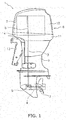
- FIG. 1 is a side view of an outboard motor 1 according to the preferred embodiment.
- the outboard motor 1 includes a mechanical power source 2, a drive shaft 3, a propeller shaft 4 and a shift mechanism 5.
- the mechanical power source 2 generates a thrust for propelling a watercraft.
- the mechanical power source 2 is an engine.
- the mechanical power source 2 includes a crankshaft 6.
- the crankshaft 6 extends in the vertical direction.
- the drive shaft 3 is connected to the crankshaft 6.
- the drive shaft 3 extends in the vertical direction.
- the drive shaft 3 downwardly extends from the mechanical power source 2. It should be noted that the drive shaft 3 may be disposed to be coaxial to, be side by side with, or be perpendicular to the crankshaft 6.
- the propeller shaft 4 extends in the back-and-forth direction.
- the propeller shaft 4 is connected to the drive shaft 3 through the shift mechanism 5.
- a propeller 7 is connected to the propeller shaft 4.
- the shift mechanism 5 switches a rotational direction of power to be transmitted from the drive shaft 3 to the propeller shaft 4.
- the shift mechanism 5 includes a plurality of gears and a clutch that changes meshing of gears.
- the outboard motor 1 includes a cowl 8 and a housing 9.
- the cowl 8 accommodates the mechanical power source 2.
- the cowl 8 includes a bottom cowl 11 and a top cowl 12.
- the top cowl 12 is disposed above the bottom cowl 11.
- the top cowl 12 is detachably attached to the bottom cowl 11.
- the housing 9 is disposed below the cowl 8.
- the housing 9 accommodates the drive shaft 3 and the propeller shaft 4.
- the outboard motor 1 includes a bracket 13. The outboard motor 1 is attached to the watercraft through the bracket 13.
- the outboard motor 1 includes an electric supply port 14.
- the electric supply port 14 is attached to the outer surface of the bottom cowl 11. Detailedly, the electric supply port 14 is attached to the front surface of the bottom cowl 11.
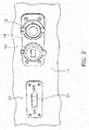
- FIG. 2 is a diagram showing the front surface of the bottom cowl 11. As shown in FIG. 2 , a waterproof cap 15 is attached to the electric supply port 14. The waterproof cap 15 is detachably attached to the electric supply port 14.
- FIG. 2 another electric supply port 16 is disposed on the front surface of the bottom cowl 11.
- the number of electric supply ports is not limited to two, and alternatively, may be one or may be three or greater.
- the electric supply port 14 supplies electric power to an accessory device 100 (see FIG. 4 ) to be connected thereto.
- the electric supply port 14 is a so-called accessory socket.
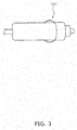
- the accessory device 100 is connected to the electric supply port 14 through, for instance, a connection plug 101 shown in FIG. 3 (see e.g., ISO 4165, JIS D 5807-91, SAE J563, etc.).
- the accessory device 100 may be a mobile device such as a feature phone or a smartphone, or alternatively, an electric charger for the mobile device.
- the accessory device 100 may be an audio and visual device such as a TV set or a DVD player.
- the accessory device 100 may be another type of device to be driven by electric power.
- FIG. 4 is a schematic diagram showing an electric system of the outboard motor 1 according to a first preferred embodiment.
- the outboard motor 1 includes an electric power generator 17.
- the electric power generator 17 is connected to the mechanical power source 2.
- the electric power generator 17 generates electric power when driven by the mechanical power source 2.
- the outboard motor 1 includes an electric circuit 18, mechanical power source auxiliary machines 19 and an ECU 20.
- the mechanical power source auxiliary machines 19 are devices for driving the mechanical power source 2.
- the mechanical power source auxiliary machines 19 include a fuel injection device, an ignition device and so forth.
- the ECU 20 controls the mechanical power source 2.
- the ECU 20 includes a computing unit such as a CPU and storage devices such as an RAM and an ROM.
- the ECU 20 controls the mechanical power source 2, for instance, such that the output rotational velocity of the mechanical power source 2 becomes a desired target value.
- the ECU 20 controls fuel injection by the fuel injection device.
- the ECU 20 controls the timing of ignition by the ignition device.
- the electric circuit 18 electrically connects the electric power generator 17 to the mechanical power source auxiliary machines 19 and the ECU 20.
- the electric circuit 18 includes a rectifier/regulator 21. Electric power generated by the electric power generator 17 is supplied to the mechanical power source auxiliary machines 19 and the ECU 20 through the electric circuit 18.
- the electric power generator 17 and the electric supply port 14 are electrically connected through the electric circuit 18. The electric power generated by the electric power generator 17 is supplied to the electric supply port 14 through the electric circuit 18.
- the outboard motor 1 is a batteryless outboard motor without any battery. Therefore, the electric power generator 17 functions as an electric power source that supplies electric power to the mechanical power source auxiliary machines 19, the ECU 20 and the electric supply port 14.
- the outboard motor 1 includes a switch 22.
- the switch 22 is disposed between the electric power generator 17 and the electric supply port 14 in the electric circuit 18.
- the switch 22 is switchable between an ON-state and an OFF-state.
- the ON-state allows the flow of electric current, whereas the OFF-state interrupts the flow of electric current.
- the switch 22 is switched from the ON-state to the OFF-state by excessive electric current. In other words, when the electric current flowing into the switch 22 has a predetermined value or greater, the switch 22 is turned to the OFF-state.
- the switch 22 is a circuit breaker.
- the switch 22 includes an electromagnet and a pair of contacts. When the electric current flowing into the electromagnet has the predetermined value or greater, the pair of contacts is separated by the electromagnetic force of the electromagnet. Accordingly, the switch 22 is turned to the OFF-state.
- the switch 22 includes an operating member 23.
- the operating member 23 is a member for manually switching the switch 22 from the OFF-state to the ON-state. A user is allowed to return the switch 22 from the OFF-state to the ON-state by manually moving the operating member 23 from an off position to an on position.
- the operating member 23 is attached to the front surface of the bottom cowl 11. In other words, the operating member 23 is attached to the cowl 8 so as to be accessible from the outside of the cowl 8.
- the operating member 23 is attached, together with the electric supply port 14, to the front surface of the bottom cowl 11. It should be noted that the operating member 23 may be disposed on a different location from the electric supply port 14.
- electric power can be supplied to the accessory device 100 by connecting the accessory device 100 to the electric supply port 14. Additionally, when electric power supplied to the accessory device 100 becomes excessive, the switch 22 is switched from the ON-state to the OFF-state, whereby the electric power supply to the accessory device 100 is interrupted. Accordingly, the amount of electric power supplied to the accessory device 100 can be limited, and electric power can be reliably supplied to the mechanical power source auxiliary machines 19.
- the switch 22 is returnable from the OFF-state to the ON-state. Therefore, electric power can be supplied again to the accessory device 100 by switching the switch 22 from the OFF-state to the ON-state without detaching the cowl 8 and then replacing the switch 22. Accordingly, electric power can be supplied to the accessory device 100 easily and stably on the watercraft.
- the mechanical power source 2 is not limited to the engine, and may be another type of device such as an electric motor.
- the attachment location for the electric supply port 14 is not limited to the bottom cowl 11, and may be another location such as the top cowl 12 or the housing 9.
- the attachment location for the operating member 23 of the switch 22 is not limited to the bottom cowl 11, and may be another location such as the top cowl 12, the housing 9 or a tiller handle.
- the electric supply port 14 is not limited to the accessory socket, and may be another type of connection port such as a USB (Universal Serial Bus).
- USB Universal Serial Bus
- the outboard motor 1 is of a batteryless type.
- the outboard motor 1 may include a battery.
- FIG. 5 is a schematic diagram showing an electric system of the outboard motor 1 according to a second preferred embodiment.
- the outboard motor 1 according to the second preferred embodiment includes a battery 24.
- the battery 24 is connected to the electric power generator 17 through the electric circuit 18.
- the battery 24 is charged by electric power from the electric power generator 17.
- the battery 24 functions as an electric power source that supplies electric power to the electric supply port 14, the ECU 20 and the mechanical power source auxiliary machines 19.
- the electric circuit 18 includes a main switch 25.
- the outboard motor 1 includes a starter motor 26.
- the starter motor 26 is driven when supplied with the electric power from the battery 24.
- the starter motor 26 starts the mechanical power source 2.
- the electric circuit 18 includes a starter switch 27 and a starter relay 28.
- the starter relay 28 becomes a connected state, whereby electric power is supplied to the starter motor 26 from the battery 24. Accordingly, the mechanical power source 2 is started.
- the electric circuit 18 includes a main relay 29.
- the main switch 25 When the main switch 25 is turned to the ON-state, the main relay 29 becomes a connected state.
- the main relay 29 becomes the connected state, electric power is supplied from the battery 24 to the mechanical power source auxiliary machines 19 and the electric supply port 14.
- the outboard motor 1 according to the second preferred embodiment explained above can also achieve advantageous effects similar to those achieved by the outboard motor 1 according to the first preferred embodiment.
- the switch 22 is a circuit breaker that is manually returned from the OFF-state to the ON-state.
- the switch 22 may be another type of switch.
- the switch 22 may be automatically switched between the ON-state and the OFF-state in accordance with the value of electric current.
- FIG. 6 is a schematic diagram showing an electric system of the outboard motor 1 according to a third preferred embodiment.
- the outboard motor 1 includes an electric current sensor 31.
- the electric current sensor 31 detects the value of electric current in the electric circuit 18 to be supplied to the accessory device 100.
- the electric current sensor 31 inputs a signal to the switch 22 in accordance with the detected value of electric current.
- the switch 22 is automatically switched between the ON-state and the OFF-state in accordance with the signal inputted thereto from the electric current sensor 31.
- the switch 22 may be, for instance, a semiconductor switch that is switched between the ON-state and the OFF-state in accordance with the signal inputted thereto.
- the outboard motor 1 according to the third preferred embodiment explained above can also achieve advantageous effects similar to those achieved by the outboard motor 1 according to the first or second preferred embodiment. Additionally, in the outboard motor 1 according to the third preferred embodiment, even when the switch 22 is turned to the OFF-state and electric power supply to the electric supply port 14 is interrupted, the switch 22 is then automatically returned from the OFF-state to the ON-state in response to reduction in value of electric current. Accordingly, electric power can be supplied again to the accessory device 100. Therefore, even when the switch 22 is disposed in such a location as the interior of the cowl 8, which is not easily accessible from outside, electric power can be supplied easily and stably to the accessory device 100 on the watercraft.
- FIG. 7 is a perspective view of an outboard motor 1 according to a fourth preferred embodiment and a watercraft 200.
- the outboard motor 1 is attached to the watercraft 200.
- the watercraft 200 includes a cockpit 201.
- a remote control device 202 is disposed in the cockpit 201 in order to operate the output of the outboard motor 1.
- a steering device 203 is disposed in the cockpit 201 in order to steer the watercraft 200.
- the outboard motor 1 includes a cable 32.
- the electric supply port 14 is disposed in a remote location from the outboard motor 1 within the watercraft 200.
- the cable 32 extends from the outboard motor 1 within the watercraft 200, and the electric supply port 14 is connected to the electric circuit 18 through the cable 32.
- the electric supply port 14 is disposed in, for instance, the cockpit 201. Alternatively, the electric supply port 14 may be disposed in another location within the watercraft 200.
- the electric supply port 14 can be disposed in a desired location within the watercraft 200, or alternatively, may be disposed in a location outside the cowl 8 and the housing 9 such as the tiller handle attached to the outboard motor 1. Therefore, flexibility in layout of the electric supply port 14 can be enhanced.
Landscapes
- Engineering & Computer Science (AREA)
- Chemical & Material Sciences (AREA)
- Combustion & Propulsion (AREA)
- Mechanical Engineering (AREA)
- Ocean & Marine Engineering (AREA)
- General Engineering & Computer Science (AREA)
- Motor Or Generator Frames (AREA)
- Combined Controls Of Internal Combustion Engines (AREA)
Abstract
Description
- The present invention relates to an outboard motor and a watercraft with a hull having at least one outboard motor attached thereto.
- Outboard motors include a mechanical power source and a mechanical power source auxiliary machine for driving the mechanical power source. For example, an outboard motor described in
JP 2013-245560 A - The engine auxiliary machines such as the ECU, the fuel injection device and the ignition device are connected to an electric power source installed in the outboard motor, and are supplied with electric power from the electric power source. For example, the electric power source is a battery installed in the outboard motor. The outboard motor includes an electric power generator to be driven by the mechanical power source. Electric power generated by the electric power generator is stored in the battery. On the other hand, in a type of outboard motor without installation of a battery, the electric power generator functions as an electric power source, and electric power generated by the electric power generator is supplied to the engine auxiliary machines.
- There are chances that electric power supply to an accessory device is required on a watercraft. For example, if a mobile device such as a mobile phone can be charged on a watercraft, this is convenient for a person on board. To achieve this, it can be assumed to supply electric power to the accessory device from the electric power source of the outboard motor.
- However, it is required to limit electric power to be supplied to the accessory device. This is because it is required to reliably supply electric power to the mechanical power source auxiliary machines for driving the mechanical power source. A fuse can be assumed to be used as means for achieving the above. Specifically, when electric power supplied to the accessory device becomes excessive, the fuse is melted and cut off, whereby electric power supply to the accessory device is interrupted. Accordingly, excessive electric power supply to the accessory device can be suppressed, and electric power can be reliably supplied to the mechanical power source auxiliary machines.
- However, as described above, when electric power supply to the accessory device is interrupted by melting and cutting off the fuse, it is required to replace the melted and cut-off fuse by new one in order to supply electric power again to the accessory device. However, it is not easy to open a cowl of the outboard motor and perform a fuse replacement work on water. This results in a drawback that electric power cannot be supplied to the accessory device until the watercraft returns to a port.
- It is an object of the present invention to provide an outboard motor with reliably supply of electric power to a mechanical power source auxiliary machine for driving a mechanical power source. According to the present invention said object is solved by an outboard motor having the features of
independent claim 1. Preferred embodiments are laid down in the dependent claims. Accordingly, reliably supply of electric power to a mechanical power source auxiliary machine for driving a mechanical power source in an outboard motor and supply electric power to an accessory device easily and stably on a watercraft can be ensured. - An outboard motor according to an aspect includes a mechanical power source, a drive shaft, a propeller shaft, an electric power source, a mechanical power source auxiliary machine, an electric circuit, an electric supply port and a switch. The drive shaft is driven by the mechanical power source, and downwardly extends from the mechanical power source. The propeller shaft is connected to the drive shaft, and extends in a direction intersecting an axis of the drive shaft. The mechanical power source auxiliary machine drives the mechanical power source. The electric circuit electrically connects the electric power source and the mechanical power source auxiliary machine. The electric supply port is electrically connected to the electric power source through the electric circuit, and supplies an electric power to an accessory device to be connected thereto. The switch is disposed between the electric power source and the electric supply port in the electric circuit. The switch is switchable between an ON-state and an OFF-state. The switch allows a flow of an electric current when switched to the ON-state. The switch interrupts the flow of the electric current when switched to the OFF-state. The switch is switched from the ON-state to the OFF-state by an excessive electric current. The switch is returnable from the OFF-state to the ON-state.
- In the outboard motor according to the present aspect, electric power can be supplied to the accessory device by connecting the accessory device to the electric supply port. Additionally, when electric power supply to the accessory device becomes excessive, the switch is switched from the ON-state to the OFF-state, whereby electric power supply to the accessory device is interrupted. Accordingly, electric power can be reliably supplied to the mechanical power source auxiliary machine. Moreover, the switch is returnable from the OFF-state to the ON-state. Therefore, electric power can be supplied again to the accessory device by switching the switch from the OFF-state to the ON-state without replacing the switch. Accordingly, electric power can be supplied to the accessory device easily and stably on a watercraft.
-
-
FIG. 1 is a side view of an outboard motor according to a preferred embodiment. -
FIG. 2 is a diagram showing a front portion of a bottom cowl. -
FIG. 3 is a diagram showing an exemplary connection plug of an accessory device. -
FIG. 4 is a schematic diagram showing an electric system of an outboard motor according to a first preferred embodiment. -
FIG. 5 is a schematic diagram showing an electric system of an outboard motor according to a second preferred embodiment. -
FIG. 6 is a schematic diagram showing an electric system of an outboard motor according to a third preferred embodiment. -
FIG. 7 is a perspective view of an outboard motor according to a fourth preferred embodiment and a watercraft. - A preferred embodiment will be hereinafter explained with reference to drawings.
FIG. 1 is a side view of anoutboard motor 1 according to the preferred embodiment. Theoutboard motor 1 includes amechanical power source 2, adrive shaft 3, apropeller shaft 4 and ashift mechanism 5. - The
mechanical power source 2 generates a thrust for propelling a watercraft. In the present preferred embodiment, themechanical power source 2 is an engine. Themechanical power source 2 includes acrankshaft 6. Thecrankshaft 6 extends in the vertical direction. Thedrive shaft 3 is connected to thecrankshaft 6. Thedrive shaft 3 extends in the vertical direction. Thedrive shaft 3 downwardly extends from themechanical power source 2. It should be noted that thedrive shaft 3 may be disposed to be coaxial to, be side by side with, or be perpendicular to thecrankshaft 6. - The
propeller shaft 4 extends in the back-and-forth direction. Thepropeller shaft 4 is connected to thedrive shaft 3 through theshift mechanism 5. A propeller 7 is connected to thepropeller shaft 4. Theshift mechanism 5 switches a rotational direction of power to be transmitted from thedrive shaft 3 to thepropeller shaft 4. For example, theshift mechanism 5 includes a plurality of gears and a clutch that changes meshing of gears. - The
outboard motor 1 includes a cowl 8 and a housing 9. The cowl 8 accommodates themechanical power source 2. The cowl 8 includes abottom cowl 11 and atop cowl 12. Thetop cowl 12 is disposed above thebottom cowl 11. Thetop cowl 12 is detachably attached to thebottom cowl 11. - The housing 9 is disposed below the cowl 8. The housing 9 accommodates the
drive shaft 3 and thepropeller shaft 4. Theoutboard motor 1 includes abracket 13. Theoutboard motor 1 is attached to the watercraft through thebracket 13. - The
outboard motor 1 includes anelectric supply port 14. Theelectric supply port 14 is attached to the outer surface of thebottom cowl 11. Detailedly, theelectric supply port 14 is attached to the front surface of thebottom cowl 11. -
FIG. 2 is a diagram showing the front surface of thebottom cowl 11. As shown inFIG. 2 , awaterproof cap 15 is attached to theelectric supply port 14. Thewaterproof cap 15 is detachably attached to theelectric supply port 14. - It should be noted that in
FIG. 2 , anotherelectric supply port 16 is disposed on the front surface of thebottom cowl 11. However, the number of electric supply ports is not limited to two, and alternatively, may be one or may be three or greater. - The
electric supply port 14 supplies electric power to an accessory device 100 (seeFIG. 4 ) to be connected thereto. Theelectric supply port 14 is a so-called accessory socket. Theaccessory device 100 is connected to theelectric supply port 14 through, for instance, aconnection plug 101 shown inFIG. 3 (see e.g., ISO 4165, JIS D 5807-91, SAE J563, etc.). For example, theaccessory device 100 may be a mobile device such as a feature phone or a smartphone, or alternatively, an electric charger for the mobile device. Theaccessory device 100 may be an audio and visual device such as a TV set or a DVD player. Alternatively, theaccessory device 100 may be another type of device to be driven by electric power. -
FIG. 4 is a schematic diagram showing an electric system of theoutboard motor 1 according to a first preferred embodiment. As shown inFIG. 4 , theoutboard motor 1 includes anelectric power generator 17. Theelectric power generator 17 is connected to themechanical power source 2. Theelectric power generator 17 generates electric power when driven by themechanical power source 2. - The
outboard motor 1 includes anelectric circuit 18, mechanical power sourceauxiliary machines 19 and anECU 20. The mechanical power sourceauxiliary machines 19 are devices for driving themechanical power source 2. For example, the mechanical power sourceauxiliary machines 19 include a fuel injection device, an ignition device and so forth. - The
ECU 20 controls themechanical power source 2. For example, theECU 20 includes a computing unit such as a CPU and storage devices such as an RAM and an ROM. TheECU 20 controls themechanical power source 2, for instance, such that the output rotational velocity of themechanical power source 2 becomes a desired target value. TheECU 20 controls fuel injection by the fuel injection device. TheECU 20 controls the timing of ignition by the ignition device. - The
electric circuit 18 electrically connects theelectric power generator 17 to the mechanical power sourceauxiliary machines 19 and theECU 20. Theelectric circuit 18 includes a rectifier/regulator 21. Electric power generated by theelectric power generator 17 is supplied to the mechanical power sourceauxiliary machines 19 and theECU 20 through theelectric circuit 18. Theelectric power generator 17 and theelectric supply port 14 are electrically connected through theelectric circuit 18. The electric power generated by theelectric power generator 17 is supplied to theelectric supply port 14 through theelectric circuit 18. - The
outboard motor 1 according to the present preferred embodiment is a batteryless outboard motor without any battery. Therefore, theelectric power generator 17 functions as an electric power source that supplies electric power to the mechanical power sourceauxiliary machines 19, theECU 20 and theelectric supply port 14. - The
outboard motor 1 includes aswitch 22. Theswitch 22 is disposed between theelectric power generator 17 and theelectric supply port 14 in theelectric circuit 18. Theswitch 22 is switchable between an ON-state and an OFF-state. The ON-state allows the flow of electric current, whereas the OFF-state interrupts the flow of electric current. Theswitch 22 is switched from the ON-state to the OFF-state by excessive electric current. In other words, when the electric current flowing into theswitch 22 has a predetermined value or greater, theswitch 22 is turned to the OFF-state. - In the present preferred embodiment, the
switch 22 is a circuit breaker. For example, theswitch 22 includes an electromagnet and a pair of contacts. When the electric current flowing into the electromagnet has the predetermined value or greater, the pair of contacts is separated by the electromagnetic force of the electromagnet. Accordingly, theswitch 22 is turned to the OFF-state. - As shown in
FIG. 2 , theswitch 22 includes an operatingmember 23. The operatingmember 23 is a member for manually switching theswitch 22 from the OFF-state to the ON-state. A user is allowed to return theswitch 22 from the OFF-state to the ON-state by manually moving the operatingmember 23 from an off position to an on position. - The operating
member 23 is attached to the front surface of thebottom cowl 11. In other words, the operatingmember 23 is attached to the cowl 8 so as to be accessible from the outside of the cowl 8. The operatingmember 23 is attached, together with theelectric supply port 14, to the front surface of thebottom cowl 11. It should be noted that the operatingmember 23 may be disposed on a different location from theelectric supply port 14. - In the
outboard motor 1 according to the present preferred embodiment explained above, electric power can be supplied to theaccessory device 100 by connecting theaccessory device 100 to theelectric supply port 14. Additionally, when electric power supplied to theaccessory device 100 becomes excessive, theswitch 22 is switched from the ON-state to the OFF-state, whereby the electric power supply to theaccessory device 100 is interrupted. Accordingly, the amount of electric power supplied to theaccessory device 100 can be limited, and electric power can be reliably supplied to the mechanical power sourceauxiliary machines 19. - The
switch 22 is returnable from the OFF-state to the ON-state. Therefore, electric power can be supplied again to theaccessory device 100 by switching theswitch 22 from the OFF-state to the ON-state without detaching the cowl 8 and then replacing theswitch 22. Accordingly, electric power can be supplied to theaccessory device 100 easily and stably on the watercraft. - One preferred embodiment has been explained above.
- The
mechanical power source 2 is not limited to the engine, and may be another type of device such as an electric motor. The attachment location for theelectric supply port 14 is not limited to thebottom cowl 11, and may be another location such as thetop cowl 12 or the housing 9. The attachment location for the operatingmember 23 of theswitch 22 is not limited to thebottom cowl 11, and may be another location such as thetop cowl 12, the housing 9 or a tiller handle. - The
electric supply port 14 is not limited to the accessory socket, and may be another type of connection port such as a USB (Universal Serial Bus). - In the aforementioned preferred embodiment, the
outboard motor 1 is of a batteryless type. However, theoutboard motor 1 may include a battery.FIG. 5 is a schematic diagram showing an electric system of theoutboard motor 1 according to a second preferred embodiment. As shown inFIG. 5 , theoutboard motor 1 according to the second preferred embodiment includes abattery 24. Thebattery 24 is connected to theelectric power generator 17 through theelectric circuit 18. Thebattery 24 is charged by electric power from theelectric power generator 17. Thebattery 24 functions as an electric power source that supplies electric power to theelectric supply port 14, theECU 20 and the mechanical power sourceauxiliary machines 19. - In the
outboard motor 1 according to the second preferred embodiment, theelectric circuit 18 includes amain switch 25. When themain switch 25 is turned to the ON-state, electric power is supplied to theECU 20 from thebattery 24. Theoutboard motor 1 includes astarter motor 26. Thestarter motor 26 is driven when supplied with the electric power from thebattery 24. Thestarter motor 26 starts themechanical power source 2. - The
electric circuit 18 includes astarter switch 27 and astarter relay 28. When themain switch 25 and thestarter switch 27 are turned to the ON-state, thestarter relay 28 becomes a connected state, whereby electric power is supplied to thestarter motor 26 from thebattery 24. Accordingly, themechanical power source 2 is started. - The
electric circuit 18 includes amain relay 29. When themain switch 25 is turned to the ON-state, themain relay 29 becomes a connected state. When themain relay 29 becomes the connected state, electric power is supplied from thebattery 24 to the mechanical power sourceauxiliary machines 19 and theelectric supply port 14. - The
outboard motor 1 according to the second preferred embodiment explained above can also achieve advantageous effects similar to those achieved by theoutboard motor 1 according to the first preferred embodiment. - In the aforementioned exemplary embodiments, the
switch 22 is a circuit breaker that is manually returned from the OFF-state to the ON-state. However, theswitch 22 may be another type of switch. For example, theswitch 22 may be automatically switched between the ON-state and the OFF-state in accordance with the value of electric current.FIG. 6 is a schematic diagram showing an electric system of theoutboard motor 1 according to a third preferred embodiment. - As shown in
FIG. 6 , theoutboard motor 1 according to the third preferred embodiment includes an electriccurrent sensor 31. The electriccurrent sensor 31 detects the value of electric current in theelectric circuit 18 to be supplied to theaccessory device 100. The electriccurrent sensor 31 inputs a signal to theswitch 22 in accordance with the detected value of electric current. Theswitch 22 is automatically switched between the ON-state and the OFF-state in accordance with the signal inputted thereto from the electriccurrent sensor 31. Theswitch 22 may be, for instance, a semiconductor switch that is switched between the ON-state and the OFF-state in accordance with the signal inputted thereto. - The
outboard motor 1 according to the third preferred embodiment explained above can also achieve advantageous effects similar to those achieved by theoutboard motor 1 according to the first or second preferred embodiment. Additionally, in theoutboard motor 1 according to the third preferred embodiment, even when theswitch 22 is turned to the OFF-state and electric power supply to theelectric supply port 14 is interrupted, theswitch 22 is then automatically returned from the OFF-state to the ON-state in response to reduction in value of electric current. Accordingly, electric power can be supplied again to theaccessory device 100. Therefore, even when theswitch 22 is disposed in such a location as the interior of the cowl 8, which is not easily accessible from outside, electric power can be supplied easily and stably to theaccessory device 100 on the watercraft. - In the aforementioned preferred embodiments, the
electric supply port 14 is disposed on the cowl 8 of theoutboard motor 1. However, theelectric supply port 14 may be disposed outside the cowl 8 or the housing 9 of theoutboard motor 1.FIG. 7 is a perspective view of anoutboard motor 1 according to a fourth preferred embodiment and awatercraft 200. Theoutboard motor 1 is attached to thewatercraft 200. Thewatercraft 200 includes acockpit 201. Aremote control device 202 is disposed in thecockpit 201 in order to operate the output of theoutboard motor 1. Asteering device 203 is disposed in thecockpit 201 in order to steer thewatercraft 200. - The
outboard motor 1 includes acable 32. Theelectric supply port 14 is disposed in a remote location from theoutboard motor 1 within thewatercraft 200. Thecable 32 extends from theoutboard motor 1 within thewatercraft 200, and theelectric supply port 14 is connected to theelectric circuit 18 through thecable 32. Theelectric supply port 14 is disposed in, for instance, thecockpit 201. Alternatively, theelectric supply port 14 may be disposed in another location within thewatercraft 200. - In the
outboard motor 1 according to the fourth preferred embodiment explained above, theelectric supply port 14 can be disposed in a desired location within thewatercraft 200, or alternatively, may be disposed in a location outside the cowl 8 and the housing 9 such as the tiller handle attached to theoutboard motor 1. Therefore, flexibility in layout of theelectric supply port 14 can be enhanced.
Claims (13)
- An outboard motor comprising:a mechanical power source (2);a drive shaft (3) configured to be driven by the mechanical power source (2), the drive shaft (3) extending from the mechanical power source (2);a propeller shaft (4) connected to the drive shaft (3), the propeller shaft (4) extending in a direction intersecting an axis of the drive shaft (3);an electric power source (14,17);a mechanical power source auxiliary machine (19) configured to drive the mechanical power source (2);an electric circuit (18) electrically connecting the electric power source (14,17) and the mechanical power source auxiliary machine (19);an electric supply port (14) electrically connected to the electric power source (14,17) through the electric circuit (18), the electric supply port (14) is configured to supply an electric power to an accessory device (100) to be connected to the electric supply port (14); anda switch (22) disposed between the electric power source (14,17) and the electric supply port (14) in the electric circuit (18), the switch (22) is configured to be switchable between an ON-state and an OFF-state, the switch (22) is configured to allow a flow of an electric current when switched to the ON-state, the switch (22) is configured to interrupt the flow of the electric current when switched to the OFF-state, the switch (22) is configured to be switched from the ON-state to the OFF-state by an excessive electric current, the switch (22) is configured to be returnable from the OFF-state to the ON-state.
- An outboard motor according to claim 1, further comprising:a cowl (8) accommodating the mechanical power source (2), whereinthe electric supply port (14) is attached to the cowl (8).
- An outboard motor according to claim 2, wherein the cowl (8) includes:a bottom cowl (11), anda top cowl (12) disposed above the bottom cowl (11), the top cowl (12) being detachably attached to the bottom cowl (11), andthe electric supply port (14) is attached to the bottom cowl (11).
- An outboard motor according to claim 3, wherein the electric supply port (14) is attached to a front portion of the bottom cowl (11).
- An outboard motor according to claim 2, wherein the electric supply port (14) is attached to an outer surface of the cowl (8).
- An outboard motor according to claim 1, further comprising:a waterproof cap (15) detachably attached to the electric supply port (14).
- An outboard motor according to claim 1, further comprising:a cowl (8) accommodating the mechanical power source (2);a housing (9) accommodating the drive shaft (3) and the propeller shaft (4); anda cable (32) connected to the electric circuit (18), whereinthe electric supply port (14) is disposed outside the cowl (8) and the housing (9), the electric supply port (14) being connected to the electric circuit (18) through the cable (32).
- An outboard motor according to claim 1, further comprising:a cowl (8) accommodating the mechanical power source (2), whereinthe switch (22) is a circuit breaker, the switch (22) including an operating member (23) configured to be manually switched from the OFF-state to the ON-state, andthe operating member (23) is attached to the cowl (8) to be accessible from outside the cowl (8).
- An outboard motor according to claim 8, wherein
the cowl (8) includes
a bottom cowl (11), and
a top cowl (12) disposed above the bottom cowl (11), the top cowl (12) being detachably attached to the bottom cowl (11), and
the operating member (23) is attached to the bottom cowl (11). - An outboard motor according to claim 9, wherein the operating member (23) is attached to a front portion of the bottom cowl (11).
- An outboard motor according to claim 8, wherein the operating member (23) is attached to an outer surface of the cowl (8).
- An outboard motor according to claim 1, further comprising:a sensor (31) configured to detect a value of the electric current in the electric circuit (18), whereinthe switch (22) is configured to be switched between the ON-state and the OFF-state in accordance with a signal inputted to the switch (22) from the sensor (31).
- Watercraft with a hull and at least one outboard motor according to at least one of the claims 1 to 12 attached thereto, wherein the drive shaft (3) is downwardly extending from the mechanical power source (2).
Applications Claiming Priority (1)
| Application Number | Priority Date | Filing Date | Title |
|---|---|---|---|
| JP2017039360A JP6882013B2 (en) | 2017-03-02 | 2017-03-02 | Outboard motor |
Publications (2)
| Publication Number | Publication Date |
|---|---|
| EP3369917A1 true EP3369917A1 (en) | 2018-09-05 |
| EP3369917B1 EP3369917B1 (en) | 2026-04-01 |
Family
ID=60480218
Family Applications (1)
| Application Number | Title | Priority Date | Filing Date |
|---|---|---|---|
| EP17203796.2A Active EP3369917B1 (en) | 2017-03-02 | 2017-11-27 | Outboard motor |
Country Status (3)
| Country | Link |
|---|---|
| US (1) | US10023284B1 (en) |
| EP (1) | EP3369917B1 (en) |
| JP (1) | JP6882013B2 (en) |
Families Citing this family (2)
| Publication number | Priority date | Publication date | Assignee | Title |
|---|---|---|---|---|
| JP7105604B2 (en) * | 2018-05-11 | 2022-07-25 | ヤマハ発動機株式会社 | Outboard motor |
| JP2023037932A (en) * | 2021-09-06 | 2023-03-16 | ヤマハ発動機株式会社 | System and method for controlling behavior of vessel |
Citations (6)
| Publication number | Priority date | Publication date | Assignee | Title |
|---|---|---|---|---|
| US6087735A (en) * | 1997-07-23 | 2000-07-11 | Sanshin Kogyo Kabushiki Kaisha | Power circuit for marine engine |
| WO2000050767A1 (en) * | 1999-02-22 | 2000-08-31 | Roger Lehmann | Outboard mounted electrical power generating apparatus for boats |
| US6595179B1 (en) * | 1999-02-24 | 2003-07-22 | Yamaha Marine Kabushiki Kaisha | Electrical control for engine |
| US20060234566A1 (en) * | 2005-04-14 | 2006-10-19 | Yoshio Ando | Outboard-type generator |
| US20090212740A1 (en) * | 2008-02-25 | 2009-08-27 | Jimmie Doyle Felps | On-board battery supervisor |
| JP2013245560A (en) | 2012-05-23 | 2013-12-09 | Yamaha Motor Co Ltd | Outboard motor |
Family Cites Families (10)
| Publication number | Priority date | Publication date | Assignee | Title |
|---|---|---|---|---|
| US3218401A (en) * | 1961-08-17 | 1965-11-16 | Bendix Corp | Torsional and axially movable resilient rotor structure for electric switches |
| JP2692467B2 (en) * | 1991-12-09 | 1997-12-17 | ダイキン工業株式会社 | Power supply device for air conditioning controller |
| JPH07193978A (en) * | 1993-12-28 | 1995-07-28 | Tokyo Gas Co Ltd | Power interruption system |
| JPH1030493A (en) * | 1996-07-12 | 1998-02-03 | Sanshin Ind Co Ltd | Ship provided with propeller |
| JP3003675B2 (en) * | 1998-07-07 | 2000-01-31 | 株式会社デンソー | Control device for hybrid electric vehicle |
| JP2008044411A (en) * | 2006-08-10 | 2008-02-28 | Yamaha Marine Co Ltd | Outboard motor |
| JP5394156B2 (en) * | 2008-08-06 | 2014-01-22 | ヤマハ発動機株式会社 | Battery charge control device and ship equipped with the same |
| WO2011100641A1 (en) * | 2010-02-11 | 2011-08-18 | Davis Engineering, Llc | Large outboard motor for marine vessel application and related methods of making and operating same |
| TWI574489B (en) * | 2014-08-01 | 2017-03-11 | 飛爾康動力公司 | Propulsion system, motor/generator/transmission device and method of operation thereof |
| JP6671223B2 (en) * | 2016-04-12 | 2020-03-25 | ヤマハ発動機株式会社 | Ship power supply system |
-
2017
- 2017-03-02 JP JP2017039360A patent/JP6882013B2/en active Active
- 2017-11-27 EP EP17203796.2A patent/EP3369917B1/en active Active
- 2017-12-05 US US15/831,459 patent/US10023284B1/en active Active
Patent Citations (6)
| Publication number | Priority date | Publication date | Assignee | Title |
|---|---|---|---|---|
| US6087735A (en) * | 1997-07-23 | 2000-07-11 | Sanshin Kogyo Kabushiki Kaisha | Power circuit for marine engine |
| WO2000050767A1 (en) * | 1999-02-22 | 2000-08-31 | Roger Lehmann | Outboard mounted electrical power generating apparatus for boats |
| US6595179B1 (en) * | 1999-02-24 | 2003-07-22 | Yamaha Marine Kabushiki Kaisha | Electrical control for engine |
| US20060234566A1 (en) * | 2005-04-14 | 2006-10-19 | Yoshio Ando | Outboard-type generator |
| US20090212740A1 (en) * | 2008-02-25 | 2009-08-27 | Jimmie Doyle Felps | On-board battery supervisor |
| JP2013245560A (en) | 2012-05-23 | 2013-12-09 | Yamaha Motor Co Ltd | Outboard motor |
Also Published As
| Publication number | Publication date |
|---|---|
| US10023284B1 (en) | 2018-07-17 |
| EP3369917B1 (en) | 2026-04-01 |
| JP6882013B2 (en) | 2021-06-02 |
| JP2018144540A (en) | 2018-09-20 |
Similar Documents
| Publication | Publication Date | Title |
|---|---|---|
| US11148776B2 (en) | Tiller system for a marine outboard engine | |
| US9440724B2 (en) | Boat maneuvering system | |
| US8192239B2 (en) | Marine vessel propulsion system and marine vessel | |
| EP3613664B1 (en) | Hybrid type vessel propulsion apparatus | |
| US11247763B2 (en) | Marine propulsion device controller for starting/stopping engine, marine propulsion system including the same, and engine starter of marine propulsion device | |
| EP3369917B1 (en) | Outboard motor | |
| JP2010161861A (en) | Power supply system for boat | |
| EP3895981A1 (en) | Marine power supply system and method for controlling marine power supply system | |
| JP2022067892A (en) | Power source system for vessel and vessel | |
| US7195525B2 (en) | Outboard motor | |
| US20090075533A1 (en) | Watercraft | |
| EP1857357A2 (en) | Control system of a propulsion unit of a watercraft | |
| EP1770007B1 (en) | Boat | |
| EP3892530A1 (en) | Marine propulsion system and control method | |
| US9688374B2 (en) | Boat maneuvering system | |
| US10703207B2 (en) | Outboard motor | |
| EP4035989A1 (en) | Power supply system for watercraft | |
| JP6188905B1 (en) | Engine control device and ship equipped with the engine control device | |
| JP4250415B2 (en) | Outboard motor | |
| JP2020090220A (en) | Outboard motor provided with idling stop function | |
| US11530676B2 (en) | Power supply system for watercraft | |
| EP4086162A2 (en) | Marine vessel maneuvering system | |
| JP2022048497A (en) | Operation device of ship propulsion system | |
| US12163463B2 (en) | Outboard motor, engine starting system, and watercraft propulsion system | |
| JP5594174B2 (en) | Power supply device for internal combustion engine |
Legal Events
| Date | Code | Title | Description |
|---|---|---|---|
| PUAI | Public reference made under article 153(3) epc to a published international application that has entered the european phase |
Free format text: ORIGINAL CODE: 0009012 |
|
| STAA | Information on the status of an ep patent application or granted ep patent |
Free format text: STATUS: THE APPLICATION HAS BEEN PUBLISHED |
|
| AK | Designated contracting states |
Kind code of ref document: A1 Designated state(s): AL AT BE BG CH CY CZ DE DK EE ES FI FR GB GR HR HU IE IS IT LI LT LU LV MC MK MT NL NO PL PT RO RS SE SI SK SM TR |
|
| AX | Request for extension of the european patent |
Extension state: BA ME |
|
| STAA | Information on the status of an ep patent application or granted ep patent |
Free format text: STATUS: REQUEST FOR EXAMINATION WAS MADE |
|
| 17P | Request for examination filed |
Effective date: 20190222 |
|
| RBV | Designated contracting states (corrected) |
Designated state(s): AL AT BE BG CH CY CZ DE DK EE ES FI FR GB GR HR HU IE IS IT LI LT LU LV MC MK MT NL NO PL PT RO RS SE SI SK SM TR |
|
| STAA | Information on the status of an ep patent application or granted ep patent |
Free format text: STATUS: EXAMINATION IS IN PROGRESS |
|
| 17Q | First examination report despatched |
Effective date: 20210730 |
|
| RIC1 | Information provided on ipc code assigned before grant |
Ipc: F02D 41/20 20060101AFI20251010BHEP |
|
| GRAP | Despatch of communication of intention to grant a patent |
Free format text: ORIGINAL CODE: EPIDOSNIGR1 |
|
| STAA | Information on the status of an ep patent application or granted ep patent |
Free format text: STATUS: GRANT OF PATENT IS INTENDED |
|
| INTG | Intention to grant announced |
Effective date: 20251125 |
|
| GRAS | Grant fee paid |
Free format text: ORIGINAL CODE: EPIDOSNIGR3 |
|
| GRAA | (expected) grant |
Free format text: ORIGINAL CODE: 0009210 |
|
| STAA | Information on the status of an ep patent application or granted ep patent |
Free format text: STATUS: THE PATENT HAS BEEN GRANTED |
|
| AK | Designated contracting states |
Kind code of ref document: B1 Designated state(s): AL AT BE BG CH CY CZ DE DK EE ES FI FR GB GR HR HU IE IS IT LI LT LU LV MC MK MT NL NO PL PT RO RS SE SI SK SM TR |
|
| REG | Reference to a national code |
Ref country code: CH Ref legal event code: F10 Free format text: ST27 STATUS EVENT CODE: U-0-0-F10-F00 (AS PROVIDED BY THE NATIONAL OFFICE) Effective date: 20260401 Ref country code: GB Ref legal event code: FG4D |
|
| REG | Reference to a national code |
Ref country code: DE Ref legal event code: R096 Ref document number: 602017094552 Country of ref document: DE |
|
| REG | Reference to a national code |
Ref country code: IE Ref legal event code: FG4D |