EP3369892A1 - Konturierung einer schaufelgitterplattform - Google Patents
Konturierung einer schaufelgitterplattform Download PDFInfo
- Publication number
- EP3369892A1 EP3369892A1 EP17159076.3A EP17159076A EP3369892A1 EP 3369892 A1 EP3369892 A1 EP 3369892A1 EP 17159076 A EP17159076 A EP 17159076A EP 3369892 A1 EP3369892 A1 EP 3369892A1
- Authority
- EP
- European Patent Office
- Prior art keywords
- blade
- platform
- edge
- segment
- upstream
- Prior art date
- Legal status (The legal status is an assumption and is not a legal conclusion. Google has not performed a legal analysis and makes no representation as to the accuracy of the status listed.)
- Granted
Links
Images
Classifications
-
- F—MECHANICAL ENGINEERING; LIGHTING; HEATING; WEAPONS; BLASTING
- F01—MACHINES OR ENGINES IN GENERAL; ENGINE PLANTS IN GENERAL; STEAM ENGINES
- F01D—NON-POSITIVE DISPLACEMENT MACHINES OR ENGINES, e.g. STEAM TURBINES
- F01D5/00—Blades; Blade-carrying members; Heating, heat-insulating, cooling or antivibration means on the blades or the members
- F01D5/12—Blades
- F01D5/14—Form or construction
- F01D5/141—Shape, i.e. outer, aerodynamic form
- F01D5/145—Means for influencing boundary layers or secondary circulations
-
- F—MECHANICAL ENGINEERING; LIGHTING; HEATING; WEAPONS; BLASTING
- F01—MACHINES OR ENGINES IN GENERAL; ENGINE PLANTS IN GENERAL; STEAM ENGINES
- F01D—NON-POSITIVE DISPLACEMENT MACHINES OR ENGINES, e.g. STEAM TURBINES
- F01D5/00—Blades; Blade-carrying members; Heating, heat-insulating, cooling or antivibration means on the blades or the members
- F01D5/12—Blades
- F01D5/14—Form or construction
- F01D5/141—Shape, i.e. outer, aerodynamic form
- F01D5/142—Shape, i.e. outer, aerodynamic form of the blades of successive rotor or stator blade-rows
- F01D5/143—Contour of the outer or inner working fluid flow path wall, i.e. shroud or hub contour
-
- F—MECHANICAL ENGINEERING; LIGHTING; HEATING; WEAPONS; BLASTING
- F01—MACHINES OR ENGINES IN GENERAL; ENGINE PLANTS IN GENERAL; STEAM ENGINES
- F01D—NON-POSITIVE DISPLACEMENT MACHINES OR ENGINES, e.g. STEAM TURBINES
- F01D9/00—Stators
- F01D9/02—Nozzles; Nozzle boxes; Stator blades; Guide conduits, e.g. individual nozzles
- F01D9/04—Nozzles; Nozzle boxes; Stator blades; Guide conduits, e.g. individual nozzles forming ring or sector
- F01D9/041—Nozzles; Nozzle boxes; Stator blades; Guide conduits, e.g. individual nozzles forming ring or sector using blades
-
- F—MECHANICAL ENGINEERING; LIGHTING; HEATING; WEAPONS; BLASTING
- F05—INDEXING SCHEMES RELATING TO ENGINES OR PUMPS IN VARIOUS SUBCLASSES OF CLASSES F01-F04
- F05D—INDEXING SCHEME FOR ASPECTS RELATING TO NON-POSITIVE-DISPLACEMENT MACHINES OR ENGINES, GAS-TURBINES OR JET-PROPULSION PLANTS
- F05D2220/00—Application
- F05D2220/30—Application in turbines
-
- F—MECHANICAL ENGINEERING; LIGHTING; HEATING; WEAPONS; BLASTING
- F05—INDEXING SCHEMES RELATING TO ENGINES OR PUMPS IN VARIOUS SUBCLASSES OF CLASSES F01-F04
- F05D—INDEXING SCHEME FOR ASPECTS RELATING TO NON-POSITIVE-DISPLACEMENT MACHINES OR ENGINES, GAS-TURBINES OR JET-PROPULSION PLANTS
- F05D2240/00—Components
- F05D2240/10—Stators
- F05D2240/12—Fluid guiding means, e.g. vanes
- F05D2240/129—Cascades, i.e. assemblies of similar profiles acting in parallel
-
- F—MECHANICAL ENGINEERING; LIGHTING; HEATING; WEAPONS; BLASTING
- F05—INDEXING SCHEMES RELATING TO ENGINES OR PUMPS IN VARIOUS SUBCLASSES OF CLASSES F01-F04
- F05D—INDEXING SCHEME FOR ASPECTS RELATING TO NON-POSITIVE-DISPLACEMENT MACHINES OR ENGINES, GAS-TURBINES OR JET-PROPULSION PLANTS
- F05D2240/00—Components
- F05D2240/80—Platforms for stationary or moving blades
Definitions
- the present invention relates to a blade grid segment, a blade grid, a platform and a blade channel of a turbomachine and a turbomachine.
- Turbomachines such as gas and steam turbines regularly have a flow channel for the passage of a fluid.
- the flow channel also referred to as an annulus, is bounded radially inwardly by the shaft of a rotor and radially outward by a housing, the terms "radial” as well as “axial” and “circumferential direction” and terms derived therefrom are in this Scripture - unless otherwise stated - always to understand a (intended) rotation axis of the rotor.
- blade grids are arranged (for which the term “blade ring” is common). They each include vanes or blades that are circumferentially spaced one behind the other at substantially regular intervals, and associated platforms, also referred to as “deck plates", each having an upstream and a downstream platform edge. These platform edges limit the blade surface (or blades) facing platform surface in the axial direction.
- the edge of the platform referred to as the "upstream” platform edge is referred to as the (axial) main flow passing through the annulus of the turbomachine during operation, as the “downstream edge” corresponding to the other edge.
- the statements “downstream” and “upstream” respectively refer to the main axial flow direction and thereby only to the axial position, that is to say regardless of a possible displacement in the circumferential direction.
- a point is to be understood as “downstream of the leading edges”. if it is arranged offset to a direct connection of the leading edges on the platform surface axially in the main flow direction.
- the pressure side of a blade and the suction side of an adjacent blade define in the circumferential direction in each case a so-called blade channel.
- a blade channel In the radial direction of this blade channel is limited within the turbomachine by so-called side walls.
- blade intermediate strip The section of the platform surface, which in the axial direction by the direct connections of the leading edges or the trailing edges of adjacent blades on the platform surface (or by a projection of a straight connection of said edges in the radial direction on the platform surface) and in the circumferential direction by the suction or pressure side is limited, is referred to in this document as "blade intermediate strip".
- the width of the blade intermediate strip in the circumferential direction is called the "pitch" of the blade grid. In particular, it can be measured as the distance of the leading edges of respectively adjacent blades in the circumferential direction on the platform surface.
- the depth of the blade clearance in the axial direction ie the distance of the leading edges of the blades from their trailing edges measured parallel to the intended axis of rotation of the turbomachine, is referred to as "grid width".
- a fluid flow guided through a flow channel is regularly influenced by the surfaces of the side walls. Flow layers that run close to these surfaces are deflected more strongly because of their lower velocity than laterally from the sidewalls flow layers. This creates a secondary flow, which is superimposed on an axial main flow and which leads in particular to eddies and pressure losses.
- contouring in the form of elevations and / or depressions is frequently introduced into the side walls.
- a flow channel with a side wall which has a radial recess in the region of the leading edges of the blades. This extends in the axial direction over the majority of the flow channel and ends only shortly before or even behind the trailing edges. This is intended to locally increase the surface area of the flow area between the inflow and outflow edges, which should improve the efficiency of the rotor.
- the EP 2 372 088 A2 discloses an integrally machined turbine blade disk having a rim with upstream and downstream edges between which blades and, in the region of the leading edges of the rotor blades, indentations in the rim surface are arranged.
- the object of the present invention is to provide an alternative technique for a turbomachine with which secondary flows can advantageously be reduced.
- a vane grate segment for a vane grille of a turbomachine comprises a platform and at least two (adjacent) airfoils which, in accordance with the above, define an airfoil blade with axial grid width by their upstream and downstream edges on the platform surface.
- the platform has an upstream platform edge that has a contour with a depression. In the axial direction, this depression extends at most by 10% of the grid width in the blade intermediate strip. In particular, the depression can be arranged completely upstream of the leading edges, ie not project into the blade intermediate strip.
- the depression is thus to be understood as a local expression of a line which extends from the cross-section of one in the two-dimensional one Platform surface lying (area) depression along the platform edge results.
- a “depression” is to be understood in this document, a local shape in the platform surface in which this extends to the side facing away from the blades.
- the term (as well as terms such as “lowered” or the like) is therefore based on an orientation or a coordinate system in which the blades extend from the platform surface "up” and a depression accordingly in the opposite direction (to “down” ) leads.
- the recess is thus arranged completely in the interior of a surface strip of the platform surface whose downstream boundary extends in the axial direction by at most 10% of the grid width downstream of the leading edges; especially against this limitation, the depression is lowered in all its points (one edge of the depression can not be considered as belonging to it).
- the recess is preferably formed contiguous. According to a specific embodiment, the downstream boundary extends even no further than (at most) 5% of the grid width downstream of the leading edges of the airfoils.
- a vane grating segment according to the invention may be in one piece or assembled.
- the platform may be unitary or comprise two or more parts each of which projects from one of the airfoils, or the platform may be formed as at least one separate component disposed between the airfoils.
- a platform according to the invention is adapted to abut in the circumferential direction on each side of an airfoil and with the blades (none, one or both of which can be integrally formed on the platform / can) together an inventive blade grid segment according to one of the disclosed in this document Embodiments form.
- a blade lattice according to the invention comprises at least one blade lattice segment according to the invention according to one of the embodiments disclosed in this document.
- a turbomachine according to the invention comprises one or more vane grates according to the invention.
- An inventive blade channel leads through an inventive Blade grating segment according to one of the embodiments disclosed in this document, is thus limited by such a blade grid segment as well as a side wall opposite the platform surface (facing the platform surface).
- the blade channel is bounded in the circumferential direction by the pressure side of one of the blade leaves of the blade grid segment and by the opposite suction side of the (adjacent) other of the blade leaves.
- An inventive blade lattice segment, a blade lattice according to the invention, a blade channel according to the invention, a platform according to the invention and a turbomachine according to the invention make it possible to improve the secondary flows and thus to reduce losses in the respective hub or housing area. Thus, a high efficiency of the turbomachine can be achieved.
- the blade lattice segment or the blade lattice or the flow channel or the platform may in particular be part of a low-pressure turbine.
- the airfoil may be a vane grille or a blade airfoil, so the airfoils may be each guide or blade airfoils.
- the platform may be configured to limit a blade channel radially inwardly or radially outwardly through the blade grid segment.
- the upstream-side platform edge is preferably configured to be (at least substantially) adjacent to another (separate) element (eg, the hub or housing or other airfoil) in the turbomachine. It may be adapted to form a portion of a wall of a gap through which cooling fluid is introduced into the annulus of the turbomachine.
- the upstream-side platform edge (which may include portions of multiple parts of a multi-part platform) is preferably bounded by the (circumferential) positions of the leading edges of the two airfoils; These boundaries may have a physical character (eg, where the platform ends up in peripheral vision in them) or may be defined or defined only abstractly to define the upstream edge of the platform.
- the upstream side edge of the platform preferably has an extent (or length) in the circumferential direction that is (substantially) equal to the pitch.
- an embodiment of the present invention has been found in which the recess along the upstream platform edge (preferably continuously) over at least 50% of the pitch extends.
- the recess has a positive distance (> 0) from the pressure side of one airfoil and / or from the suction side of the other airfoil so that it does not touch the respective side.
- the recess may be the same or different distances from the two blades.
- the distance from the recess to the leading edge of one blade e.g., at the pressure side of which the blade clearance area is adjacent
- the distance between the depression and the leading edge of the other blade may be greater or less than the distance between the depression and the leading edge of the other blade.
- an embodiment of the present invention has proven to be advantageous in which the inflow-side platform edge (or its contour) is formed asymmetrically to its radial center axis, ie a radial axis which extends through the center of the inflow-side platform edge.
- the platform surface comprises a surface area disposed between the recess and a pressure side of (a first one of) the airfoils.
- a surface area is detected by the upstream platform edge.
- the contour of the inflow-side platform edge then includes an edge of the surface area, which is referred to below as the "pressure-side" surface area.
- an edge portion of the inflow-side platform edge, in which it detects the pressure-side surface area preferably extend in the circumferential direction over at least 10% or at least 20% of the pitch.
- Each point of the recess is preferably lowered in comparison with each point of the pressure-side surface area (in the radial direction).
- the platform surface may include a surface area disposed between the recess and a suction side of the other (second) of the airfoils.
- a surface area of the upstream platform edge detected.
- the contour of the inflow-side platform edge then includes an edge of the surface area, which is referred to below as the "suction-side" surface area.
- an edge portion of the inflow-side platform edge, in which it detects the suction-side surface area preferably extend in the circumferential direction over at least 10% or at least 20% of the pitch.
- Each point of the recess is preferably lowered in comparison with each point of the suction-side surface area (in the radial direction).
- the platform surface therefore comprises both a pressure-related and a suction-side surface section (possibly with the other properties mentioned).
- an edge section in which the inflow-side platform edge detects the suction-side surface area, is larger than an edge section of the inflow-side platform edge, in which it detects the suction-side area area; in another variant, it is reversed, and in another embodiment, both sections are the same size.
- the platform surface may be formed without contours.
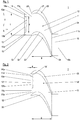
- FIG. 1 is schematically an exemplary (developed) embodiment of a Shovel segment 1 according to the invention shown in plan view; the viewing direction corresponds to the radial direction (outward or inward, depending on whether the platform 10 is part of an outer or an inner side wall).
- the airfoil segment comprises adjacent airfoils 20, 30 and a platform 10 according to the invention, which has a platform surface 12, a platform edge 10a (based on the intended axial main flow direction X), and a downstream platform edge 10b.
- the upstream platform edge 10a may comprise portions of multiple parts of a multi-part platform. It is limited by the (circumferential) positions of the leading edges 23, 33 of the two blades 20, 30; In particular, the extent (or length) of the inflow-side platform edge 10a in the circumferential direction is thus equal to the pitch t.
- the pressure side 21 of one airfoil 20 and the suction side 32 of the other airfoil 30 delimit in the circumferential direction U of the associated airfoil a blade intermediate strip 11; in the axial direction, this blade intermediate strip is delimited by a straight connection 11a of the leading edges 23, 33 on the one hand and by a corresponding connection 11b of the trailing edges 24, 34 of the blades 20, 30 in the plan view (ie, a corresponding projection) along the platform.
- the platform surface has a depression 13 which is captured by the upstream platform edge 10a.
- the upstream platform edge 10a In cross-section (along a plane to which the intended axis of rotation is normal) it follows that the upstream platform edge 10a has a contour with the depression 13 (in the form of a depression) (not directly shown in the figure, but implied by it) ,
- the depression is arranged completely upstream of the blade intermediate strip 11 in the illustrated example. It extends along the upstream platform edge 10a contiguous (ie, continuous) over an extent d that is greater than 50% of the pitch t.
- an outflow-side boundary 13b of the recess 13 has a changing with its course axial distance to the inflow-side platform edge 10a;
- a downstream boundary of the recess 13 could extend substantially without axial deviations in the circumferential direction U, in a radial projection on the Platform surface so parallel to the upstream platform edge 10 a (not shown).
- the platform surface has a pressure-side surface portion 14 disposed between the pressure side 21 of the airfoil 20 and the recess 13 and approaching the front platform edge 10a, and a suction-side surface portion 15 located between the suction side 32 of the airfoil 30 and the recess 13 and approaching the front platform edge ,
- the depression 13 is completely lowered in the radial direction in comparison with each point of the pressure-side section 14 and each point of the suction-side section 15 (which is again not visible in the figure as a plan view due to the illustration).
- the pressure-side surface portion 14 reaching toward the front platform edge 10a extends in a continuous edge portion 14a along the front platform edge 10a.
- the suction-side portion 15 extending to the front platform edge extends in a continuous edge portion 15a along the front platform edge 10a. I'm in the FIG. 1 As shown, the edge portion 15a is smaller than the edge portion 14a.
- the inflow-side platform edge 10a is asymmetrical to its (not shown in the figure) radial central axis, ie to a radial axis which passes through the center of the inflow-side platform edge 10a.
- FIG. 2 schematically shows a developed alternative embodiment of a blade grid segment 1 according to the invention in plan view. It points like that in FIG. 1 Shovel segment 1 shown blade airfoils 20, 30 and a platform 10 according to the invention with a (based on the intended, axial main flow direction X) upstream platform edge 10a and a downstream platform edge 10b on.
- the platform surface of the platform 10 of the airfoil segment 1 ' comprises a depression 13' running along the upstream side edge 10a of the platform 10a which is on the upstream side.
- a contour in the inflow-side platform edge 10a results in the depression 13 'in the form of a contiguous depression.
- a downstream boundary 13'b of the recess 13 ' also has in the FIG. 2 Example shown a changing with its course distance in the axial direction to the upstream platform edge 10a on;
- a downstream boundary of the recess extends substantially without axial deviations in the circumferential direction (ie, in the projection on the platform surface parallel to the inflow-side platform edge 10a).
- the recess 13 ' is in the interior of a surface strip of the platform surface 12' is arranged, the downstream boundary extends in the circumferential direction and the axial distance a downstream of the leading edges 23, 33 of the blades 20, 30.
- a ⁇ 0.1 g where g is the axial grid width.
- the depression 13 'thus protrudes at most 10% of the axial grid width g into the blade intermediate strip 11.
- the platform surface has a pressure-side surface portion 14 'disposed between the pressure side 21 of the airfoil 20 and the recess 13' and reaching the front platform edge 11, and a suction side disposed between the suction side 32 of the airfoil 30 and the recess 13 'and approaching the front platform edge Surface portion 15 'on.
- the recess 13 ' is compared to each point of the pressure-side portion 14' and each point of the suction-side portion 15 'completely lowered in the radial direction (which is again not visible in the figure due to the representation as a plan view).
- the pressure-side surface portion 14 'extending toward the front platform edge extends continuously along the front platform edge 10a in an edge portion 14'a.
- the suction-side portion 15 'extending to the front platform edge extends continuously along the front platform edge 10a in an edge portion 15'a.
- the edge portion 15'a is larger than the edge portion 14'a; in a particular embodiment, the edge portion 15'a may be at least 1.5 times or even at least twice as large as the edge portion 14'a.
- a blade lattice segment 1, 1 'for a blade lattice of a turbomachine comprising a platform 10 and at least two blades 20, 30, by their arrival and trailing edges 23, 33, 24, 34 on the platform surface, an intermediate blade strip 11 with axial grid width Determine g.
- An upstream side Platform edge 10a has a contour with a recess 13, 13 '. In the axial direction, this depression 13, 13 'extends at most by 10% of the grating width g in the blade intermediate strips 11.
Landscapes
- Engineering & Computer Science (AREA)
- Physics & Mathematics (AREA)
- Fluid Mechanics (AREA)
- Mechanical Engineering (AREA)
- General Engineering & Computer Science (AREA)
- Turbine Rotor Nozzle Sealing (AREA)
Abstract
Description
- Die vorliegende Erfindung betrifft ein Schaufelgittersegment, ein Schaufelgitter, eine Plattform und einen Schaufelkanal einer Strömungsmaschine sowie eine Strömungsmaschine.
- Strömungsmaschinen (wie Gas- und Dampfturbinen) weisen regelmäßig einen Strömungskanal zur Durchführung eines Fluids auf. Der Strömungskanal, der auch als Ringraum" bezeichnet wird, ist nach radial innen durch die Welle eines Rotors begrenzt und nach radial außen durch ein Gehäuse; die Bezeichnungen "radial" ebenso wie "axial" und "Umfangsrichtung" sowie davon abgeleitete Begriffe sind in dieser Schrift - sofern nichts anderes angegeben ist - stets auf eine (vorgesehene) Rotationsachse des Rotors zu verstehen.
- Im Ringraum einer Strömungsmaschine sind Schaufelgitter angeordnet (für die auch die Bezeichnung "Schaufelkranz" üblich ist). Sie umfassen jeweils Leit- oder Laufschaufeln, die in Umfangsrichtung in im Wesentlichen regelmäßigen Abständen hintereinanderliegen, sowie zugehörige Plattformen, die auch als "Deckplatten" bezeichnet werden und die jeweils eine anströmseitige und eine abströmseitige Plattformkante aufweisen. Diese Plattformkanten begrenzen die den Schaufeln (bzw. Schaufelblättern) zugewandte Plattformoberfläche in axialer Richtung.
- Als "anströmseitige" Plattformkante wird dabei in dieser Schrift der Rand der Plattform bezeichnet, den der im Betrieb durch den Ringraum der Strömungsmaschine führende (axiale) Hauptstrom zuerst passiert, als "abströmseitige" Plattformkante entsprechend der andere Rand. Die Angaben "stromab" bzw. "stromauf" beziehen sich entsprechend auf die axiale Hauptstromrichtung und dabei lediglich auf die axiale Position, also ungeachtet einer möglichen Verschiebung in Umfangsrichtung: Insbesondere ist in dieser Schrift ein Punkt als "stromab der Anströmkanten" liegend zu verstehen, wenn er zu einer direkten Verbindung der Anströmkanten an der Plattformoberfläche axial in Hauptstromrichtung versetzt angeordnet ist.
- Die Druckseite einer Schaufel und die Saugseite einer benachbarten Schaufel begrenzen in Umfangsrichtung jeweils einen sogenannten Schaufelkanal. In radialer Richtung wird dieser Schaufelkanal innerhalb der Strömungsmaschine durch sogenannte Seitenwände begrenzt.
- Diese werden zum einen durch die Plattformen gebildet, zum anderen durch diesen Plattformen radial gegenüberliegende Abschnitte: Im Falle von Laufschaufeln ist eine derartige Seitenwand dabei ein radial außen liegender Abschnitt (insbesondere des Gehäuses), im Falle von Leitschaufeln ein radial innen liegender Abschnitt (insbesondere einer Rotornabe).
- Der Abschnitt der Plattformoberfläche, der in axialer Richtung durch die direkten Verbindungen der Anströmkanten bzw. der Abströmkanten benachbarter Schaufelblätter an der Plattformoberfläche (bzw. durch eine Projektion einer geraden Verbindung der genannten Kanten in radialer Richtung auf die Plattformoberfläche) sowie in Umfangsrichtung durch deren Saug- bzw. Druckseite begrenzt ist, wird in dieser Schrift als "Schaufelzwischenstreifen" bezeichnet. Die Breite des Schaufelzwischenstreifens in Umfangsrichtung wird "Teilungsabstand" des Schaufelgitters genannt. Er kann insbesondere als Abstand der Anströmkanten jeweils benachbarter Schaufeln in Umfangsrichtung an der Plattformoberfläche gemessen werden. Die Tiefe des Schaufelzwischenraums in axialer Richtung, also der parallel zur vorgesehenen Rotationsachse der Strömungsmaschine gemessene Abstand der Anströmkanten der Schaufelblätter von deren Abströmkanten wird als "Gitterbreite" bezeichnet.
- Eine durch einen Strömungskanal geführte Fluidströmung wird regelmäßig durch die Oberflächen der Seitenwände beeinflusst. Strömungsschichten, die nahe an diesen Oberflächen verlaufen, werden dabei aufgrund ihrer geringeren Geschwindigkeit stärker abgelenkt als von den Seitenwänden fernere Strömungsschichten. So entsteht eine Sekundärströmung, die einem axialen Hauptstrom überlagert ist und die insbesondere zu Wirbeln und Druckverlusten führt.
- Zur Verringerung der Sekundärströmungen werden in die Seitenwände häufig Konturierungen in Form von Erhebungen und/oder Vertiefungen eingebracht.
- Aus dem Stand der Technik ist eine Vielzahl von derartigen sogenannten "Seitenwandkonturierungen" bekannt. Exemplarisch seien die Patente bzw. Patentanmeldungen
EP 2 487 329 B1 ,EP 2 787 172 A2 , undEP 2 696 029 B1 der Anmelderin genannt. - Darüber hinaus ist aus der Druckschrift
EP 1 126 132 A2 ein Strömungskanal mit einer Seitenwand bekannt, die im Bereich der Anströmkanten der Schaufelblätter eine radiale Vertiefung aufweist. Diese erstreckt sich in axialer Richtung über den überwiegenden Teil des Strömungskanals und endet erst kurz vor oder sogar hinter den Abströmkanten. Damit soll die Oberfläche des Durchflussbereichs zwischen An- und Abströmkanten lokal vergrößert werden, was die Effizienz des Rotors verbessern soll. - Die
EP 2 372 088 A2 offenbart eine integral gefertigte Turbinenschaufelscheibe, die einen Kranz mit anströmseitigen und abströmseitigen Kanten aufweist, zwischen denen Laufschaufeln sowie - im Bereich der Anströmkanten der Laufschaufelblätter - Vertiefungen in der Kranzoberfläche angeordnet sind. - Aufgabe der vorliegenden Erfindung ist es, eine alternative Technik für eine Strömungsmaschine bereitzustellen, mit der Sekundärströme auf vorteilhafte Weise reduziert werden können.
- Die Aufgabe wird gelöst durch einen Schaufelgittersegment gemäß Anspruch 1, ein Schaufelgitter nach Anspruch 11, einen Schaufelkanal gemäß Anspruch 12, eine Plattform gemäß Anspruch 13 und eine Strömungsmaschine nach Anspruch 14. Vorteilhafte Ausführungsformen sind in den Unteransprüchen, der Beschreibung und den Figuren offenbart.
- Ein erfindungsgemäßes Schaufelgittersegment für ein Schaufelgitter einer Strömungsmaschine umfasst eine Plattform und mindestens zwei (benachbarte) Schaufelblätter, die entsprechend dem oben Genannten durch ihre An- und Abströmkanten auf der Plattformoberfläche einen Schaufelzwischenstreifen mit axialer Gitterbreite bestimmen. Die Plattform hat eine anströmseitige Plattformkante, die eine Kontur mit einer Vertiefung aufweist. In axialer Richtung erstreckt sich diese Vertiefung höchstens um 10% der Gitterbreite in den Schaufelzwischenstreifen hinein. Insbesondere kann die Vertiefung vollständig stromauf der Anströmkanten angeordnet sein, also nicht in den Schaufelzwischenstreifen hineinragen.
- Bezogen auf die anströmseitige Plattformkante ist die Vertiefung also als lokale Ausprägung einer Linie zu verstehen, die sich aus dem Querschnitt einer in der zweidimensionalen Plattformoberfläche liegenden (flächigen) Vertiefung entlang der Plattformkante ergibt. Als eine solche "Vertiefung" ist in dieser Schrift eine lokale Ausformung in der Plattformoberfläche zu verstehen, in der sich diese zur von den Schaufelblättern abgewandten Seite hin erstreckt. Der Bezeichnung (ebenso wie Begriffen wie "abgesenkt" oder ähnlichem) liegt hier also eine Orientierung bzw. ein Koordinatensystem zugrunde, bei der die Schaufelblätter sich von der Plattformoberfläche nach "oben" erstrecken und eine Vertiefung dementsprechend in die entgegengesetzte Richtung (nach "unten") führt.
- Die Vertiefung ist somit vollständig im Inneren eines Oberflächenstreifens der Plattformoberfläche angeordnet, dessen abströmseitige Begrenzung in axialer Richtung um höchstens 10% der Gitterbreite stromab der Anströmkanten verläuft; insbesondere gegenüber dieser Begrenzung ist die Vertiefung in allen ihren Punkten abgesenkt (wobei ein Rand der Vertiefung als nicht zu ihr gehörig angesehen werden kann). In der Kontur der anströmseitigen Plattformkante ist die Vertiefung vorzugsweise zusammenhängend ausgebildet. Gemäß einer speziellen Ausführungsform verläuft die abströmseitige Begrenzung sogar nicht weiter als (höchstens) 5% der Gitterbreite stromab der Anströmkanten der Schaufelblätter.
- Ein erfindungsgemäßes Schaufelgittersegment kann einteilig oder zusammengesetzt sein. Insbesondere kann die Plattform einteilig sein oder zwei oder mehr Teile umfassen, von denen jeweils eines der Schaufelblätter absteht, oder die Plattform kann als mindestens ein separates Bauteil ausgebildet sein, das zwischen den Schaufelblättern angeordnet ist oder werden kann. Entsprechend ist eine erfindungsgemäße Plattform dazu eingerichtet, in Umfangsrichtung an jeder Seite an ein Schaufelblatt anzugrenzen und mit den Schaufelblättern (von denen keines, eines oder beide fest an die Plattform angeformt sein kann/können) zusammen ein erfindungsgemäßes Schaufelgittersegment gemäß einer der in dieser Schrift offenbarten Ausführungsformen auszubilden.
- Ein erfindungsgemäßes Schaufelgitter umfasst mindestens ein erfindungsgemäßes Schaufelgittersegment gemäß einer der in dieser Schrift offenbarten Ausführungsformen. Eine erfindungsgemäße Strömungsmaschine umfasst ein oder mehrere erfindungsgemäße(s) Schaufelgitter.
- Ein erfindungsgemäßer Schaufelkanal führt durch ein erfindungsgemäßes Schaufelgittersegment gemäß einer der in dieser Schrift offenbarten Ausführungsformen, ist also durch ein derartiges Schaufelgittersegment sowie eine dessen Plattform gegenüberliegende (der Plattformoberfläche zugewandte) Seitenwand begrenzt. Insbesondere ist der Schaufelkanal in Umfangsrichtung durch die Druckseite eines der Schaufelblätter des Schaufelgittersegments und durch die dieser gegenüberliegende Saugseite des (benachbarten) anderen der Schaufelblätter begrenzt.
- Ein erfindungsgemäßes Schaufelgittersegment, ein erfindungsgemäßes Schaufelgitter, ein erfindungsgemäßer Schaufelkanal, eine erfindungsgemäße Plattform und eine erfindungsgemäße Strömungsmaschine ermöglichen jeweils eine Verbesserung der Sekundärströme und damit eine Verminderung von Verlusten im jeweiligen Naben- bzw. Gehäusebereich. So kann ein hoher Wirkungsgrad der Strömungsmaschine erzielt werden.
- Das Schaufelgittersegment bzw. das Schaufelgitter bzw. der Strömungskanal bzw. die Plattform können insbesondere Teil einer Niederdruckturbine sein. Das Schaufelgitter kann ein Leitschaufelgitter oder ein Laufschaufelgitter sein, die Schaufelblätter können also jeweils Leit- oder Laufschaufelblätter sein. Die Plattform kann dazu eingerichtet sein, einen Schaufelkanal durch das Schaufelgittersegment nach radial innen oder nach radial außen zu begrenzen.
- Die anströmseitige Plattformkante ist vorzugsweise dazu eingerichtet, (mindestens im Wesentlichen) angrenzend an ein weiteres (separates) Element (z.B. der Nabe oder des Gehäuses oder eines anderen Schaufelgitters) in der Strömungsmaschine verwendet zu werden. Sie kann dazu eingerichtet sein, einen Abschnitt einer Wandung eines Spaltes auszubilden, durch den Kühlungsfluid in den Ringraum der Strömungsmaschine eingeleitet wird bzw. werden kann. In Umfangsrichtung wird die anströmseitige Plattformkante (die Abschnitte mehrerer Teile einer mehrteiligen Plattform umfassen kann) vorzugsweise durch die (Umfangsrichtungs-)Positionen der Anströmkanten der beiden Schaufelblätter begrenzt; diese Begrenzungen können eine physikalische Ausprägung haben (z.B. indem die Plattform in Umfangsichtung in ihnen endet) oder lediglich abstrakt zur Definition der anströmseitigen Plattformkante festgelegt bzw. festzulegen sein. Insbesondere hat die anströmseitige Plattformkante vorzugsweise in Umfangsrichtung eine Ausdehnung (bzw. Länge), die (im Wesentlichen) gleich dem Teilungsabstand ist.
- Als besonders vorteilhaft hat sich eine Ausführungsform der vorliegenden Erfindung erwiesen, bei der sich die Vertiefung entlang der anströmseitigen Plattformkante (vorzugsweise durchgehend) über mindestens 50% des Teilungsabstands erstreckt.
- Vorzugsweise hat die Vertiefung eine positiven Abstand (>0) von der Druckseite des einen Schaufelblattes und/oder von der Saugseite des anderen Schaufelblattes, so dass sie die jeweilige Seite also nicht berührt. Die Vertiefung kann von den beiden Schaufelblättern gleich oder unterschiedlich weit beabstandet sein. Insbesondere kann der Abstand von der Vertiefung zur Anströmkante der einen Schaufel (z.B. der, an dessen Druckseite der Schaufelzwischenraumsbereich angrenzt) größer oder kleiner sein als der Abstand zwischen der Vertiefung und der Anströmkante der anderen Schaufel. Eine derartige axiale Asymmetrie kann einer unterschiedlichen Beeinflussung der Strömung durch Saug- und Druckseite der Schaufeln im Sinne einer Verminderung von Sekundärströmen gerecht werden.
- Insbesondere hat sich eine Ausführungsform der vorliegenden Erfindung als vorteilhaft erwiesen, bei der die anströmseitige Plattformkante (bzw. ihre Kontur) asymmetrisch zu ihrer radialen Mittelachse ausgebildet ist, also einer radialen Achse, die durch die Mitte der anströmseitigen Plattformkante verläuft.
- Bei einer bevorzugten Ausführungsvariante der vorliegenden Erfindung umfasst die Plattformoberfläche einen Flächenbereich, der zwischen der Vertiefung und einer Druckseite eines (des ersten) der Schaufelblätter angeordnet ist. Vorzugsweise wird ein derartiger Flächenbereich von der anströmseitigen Plattformkante erfasst. Die Kontur der anströmseitigen Plattformkante umfasst dann also einen Rand des Flächenbereichs, der im folgenden als "druckseitiger" Flächenbereich bezeichnet wird. Insbesondere kann sich ein Kantenabschnitt der anströmseitigen Plattformkante, in dem diese den druckseitigen Flächenbereich erfasst, in Umfangsrichtung vorzugsweise über mindestens 10% oder mindestens 20% des Teilungsabstandes erstrecken. Jeder Punkt der Vertiefung ist dabei vorzugsweise im Vergleich zu jedem Punkt des druckseitigen Flächenbereichs (in radialer Richtung) abgesenkt.
- Analog kann die Plattformoberfläche einen Flächenbereich umfassen, der zwischen der Vertiefung und einer Saugseite des anderen (zweiten) der Schaufelblätter angeordnet ist. Vorzugsweise wird ein solcher Flächenbereich von der anströmseitigen Plattformkante erfasst. Die Kontur der anströmseitigen Plattformkante umfasst dann also einen Rand des Flächenbereichs, der im folgenden als "saugseitiger" Flächenbereich bezeichnet wird. Insbesondere kann ein Kantenabschnitt der anströmseitigen Plattformkante, in dem diese den saugseitigen Flächenbereich erfasst, sich in Umfangsrichtung vorzugsweise über mindestens 10% oder mindestens 20% des Teilungsabstandes erstrecken. Jeder Punkt der Vertiefung ist dabei vorzugsweise im Vergleich zu jedem Punkt des saugseitigen Flächenbereichs (in radialer Richtung) abgesenkt.
- Als besonders vorteilhaft hat sich eine Kombination dieser Ausführungsformen erwiesen, bei der also die Plattformoberfläche sowohl einen druck- als auch einen saugseitigen Flächenabschnitt (ggf. mit den weiteren genannten Eigenschaften) umfasst. Gemäß einer Ausführungsform ist dabei ein Kantenabschnitt, in dem die anströmseitige Plattformkante den saugseitigen Flächenbereich erfasst, größer als ein Kantenabschnitt der anströmseitigen Plattformkante, in dem diese den saugseitigen Flächenbereich erfasst; bei einer anderen Variante ist es umgekehrt, und bei einer weiteren Ausführungsform sind beide Abschnitte gleich groß.
- Außerhalb der Vertiefung kann die Plattformoberfläche unkonturiert ausgebildet sein.
- Im Folgenden werden bevorzugte Ausführungsbeispiele der Erfindung anhand von Zeichnungen näher erläutert. Es versteht sich, dass einzelne Elemente und Komponenten auch anders kombiniert werden können als dargestellt. Bezugszeichen für einander entsprechende Elemente sind figurenübergreifend verwendet und werden ggf. nicht für jede Figur neu beschrieben.
- Es zeigen schematisch:
- Figur 1:
- ein abgewickeltes Schaufelgittersegment einer exemplarischen Ausführungsform der vorliegenden Erfindung in Draufsicht; und
- Figur 2:
- ein abgewickeltes Schaufelgittersegment einer alternativen exemplarischen Ausführungsform der vorliegenden Erfindung in Draufsicht.
- In
Figur 1 ist schematisch eine exemplarische (abgewickelte) Ausführungsform eines erfindungsgemäßen Schaufelgittersegments 1 in Draufsicht dargestellt; die Blickrichtung entspricht dabei der radialen Richtung (nach außen oder nach innen, je nachdem ob die Plattform 10 Teil einer äußeren oder einer inneren Seitenwand ist). Das Schaufelgittersegment umfasst benachbarte Schaufelblätter 20, 30 und eine erfindungsgemäße Plattform 10, die eine Plattformoberfläche 12, eine (bezogen auf die vorgesehene axiale Hauptstromrichtung X) anströmseitige Plattformkante 10a und eine abströmseitige Plattformkante 10b aufweist. Die anströmseitige Plattformkante 10a kann - wenngleich nicht dargestellt - Abschnitte mehrerer Teile einer mehrteiligen Plattform umfassen. Sie ist durch die (Umfangsrichtungs-)Positionen der Anströmkanten 23, 33 der beiden Schaufelblätter 20, 30 begrenzt; insbesondere ist die Ausdehnung (bzw. Länge) der anströmseitigen Plattformkante 10a in Umfangsrichtung damit gleich dem Teilungsabstand t. - Die Druckseite 21 des einen Schaufelblatts 20 und die Saugseite 32 des anderen Schaufelblatts 30 begrenzen in Umfangsrichtung U des zugehörigen Schaufelgitters einen Schaufelzwischenstreifen 11; in axialer Richtung ist dieser Schaufelzwischenstreifen durch eine entlang der Plattform verlaufende, in der Draufsicht (also einer entsprechenden Projektion) gerade Verbindung 11a der Anströmkanten 23, 33 einerseits und durch eine entsprechende Verbindung 11b der Abströmkanten 24, 34 der Schaufelblätter 20, 30 begrenzt. Es ergibt sich eine (axiale) Gitterbreite g.
- Die Plattformoberfläche weist eine Vertiefung 13 auf, die von der anströmseitigen Plattformkante 10a erfasst wird. Im Querschnitt (entlang einer Ebene, zu der die vorgesehene Rotationsachse normal ist) ergibt sich daraus, dass die anströmseitige Plattformkante 10a eine Kontur mit der Vertiefung 13 (in Form einer Senke) aufweist (in der Figur nicht unmittelbar dargestellt, aber durch sie impliziert).
- Die Vertiefung ist im dargestellten Beispiel vollständig stromauf des Schaufelzwischenstreifens 11 angeordnet. Sie erstreckt sich entlang der anströmseitigen Plattformkante 10a zusammenhängend (also durchgehend) über eine Ausdehnung d, die größer ist als 50% der Teilung t. Dabei weist eine abströmseitige Begrenzung 13b der Vertiefung 13 einen sich mit ihrem Verlauf ändernden axialen Abstand zur anströmseitigen Plattformkante 10a auf; gemäß einem anderen (nicht dargestellten) Ausführungsbeispiel könnte eine abströmseitige Begrenzung der Vertiefung 13 sich im Wesentlichen ohne axiale Abweichungen in Umfangsrichtung U erstrecken, in einer radialen Projektion auf die Plattformoberfläche also parallel zur anströmseitigen Plattformkante 10a verlaufen (nicht dargestellt).
- Die Plattformoberfläche weist einen zwischen der Druckseite 21 des Schaufelblatts 20 und der Vertiefung 13 angeordneten und an die vordere Plattformkante 10a heranreichenden druckseitigen Flächenabschnitt 14 sowie einen zwischen der Saugseite 32 des Schaufelblatts 30 und der Vertiefung 13 angeordneten und an die vordere Plattformkante heranreichenden saugseitigen Flächenabschnitt 15 auf. Die Vertiefung 13 ist dabei im Vergleich zu jedem Punkt des druckseitigen Abschnitts 14 und jedem Punkt des saugseitigen Abschnitts 15 vollständig in radialer Richtung abgesenkt (was in der Figur wiederum aufgrund der Darstellung als Draufsicht nicht sichtbar ist).
- Der an die vordere Plattformkante 10a heranreichende druckseitige Flächenabschnitt 14 erstreckt sich in einem durchgehenden Kantenabschnitt 14a entlang der vorderen Plattformkante 10a. Analog erstreckt sich der an die vordere Plattformkante heranreichende saugseitige Abschnitt 15 in einem durchgehenden Kantenabschnitt 15a entlang der vorderen Plattformkante 10a. Im in der
Figur 1 gezeigten Ausführungsbeispiel ist der Kantenabschnitt 15a kleiner als der Kantenabschnitt 14a. Insbesondere ist die anströmseitige Plattformkante 10a asymmetrisch zu ihrer (in der Figur nicht dargestellten) radialen Mittelachse, also zu einer radialen Achse, die durch die Mitte der anströmseitigen Plattformkante 10a läuft. -
Figur 2 zeigt schematisch eine abgewickelte alternative Ausführungsform eines erfindungsgemäßen Schaufelgittersegments 1 in Draufsicht. Es weist wie das inFigur 1 gezeigte Schaufelgittersegment 1 Schaufelblätter 20, 30 und eine erfindungsgemäße Plattform 10 mit einer (bezogen auf die vorgesehene, axiale Hauptstromrichtung X) anströmseitigen Plattformkante 10a und einer abströmseitige Plattformkante 10b auf. - Die Plattformoberfläche der Plattform 10 des Schaufelgittersegments 1' umfasst eine entlang der anströmseitigen Plattformkante 10a verlaufende Vertiefung 13', die von der anströmseitigen Plattformkante 10a erfasst wird. Im Querschnitt (entlang einer Ebene, zu der die vorgesehene Rotationsachse normal ist) ergibt sich auch hier eine die Vertiefung 13' in Form einer zusammenhängenden Senke umfassende Kontur in der anströmseitigen Plattformkante 10a (in der Figur wiederum nicht unmittelbar dargestellt, aber durch sie impliziert).
- Eine abströmseitige Begrenzung 13'b der Vertiefung 13' weist auch im in der
Figur 2 gezeigten Beispiel einen sich mit ihrem Verlauf ändernden Abstand in axialer Richtung zur anströmseitigen Plattformkante 10a auf; gemäß anderen (nicht gezeigten) Ausführungsbeispielen erstreckt sich eine abströmseitige Begrenzung der Vertiefung im Wesentlichen ohne axiale Abweichungen in Umfangsrichtung (verläuft also in der Projektion auf die Plattformoberfläche parallel zur anströmseitigen Plattformkante 10a). Die Vertiefung 13' ist dabei im Inneren eines Oberflächenstreifens der Plattformoberfläche 12' angeordnet, dessen abströmseitige Begrenzung in Umfangsrichtung verläuft und um den axialen Abstand a stromab der Anströmkanten 23, 33 der Schaufelblätter 20, 30 liegt. Erfindungsgemäß gilt dabei a ≤ 0,1g, wobei g die axiale Gitterbreite ist. Die Vertiefung 13' ragt somit höchstens 10% der axialen Gitterbreite g in den Schaufelzwischenstreifen 11 hinein. - Die Plattformoberfläche weist einen zwischen der Druckseite 21 des Schaufelblatts 20 und der Vertiefung 13' angeordneten und an die vordere Plattformkante 11 heranreichenden druckseitigen Flächenabschnitt 14' sowie einen zwischen der Saugseite 32 des Schaufelblatts 30 und der Vertiefung 13' angeordneten und an die vordere Plattformkante heranreichenden saugseitigen Flächenabschnitt 15' auf. Die Vertiefung 13' ist dabei im Vergleich zu jedem Punkt des druckseitigen Abschnitts 14' und jedem Punkt des saugseitigen Abschnitts 15' vollständig in radialer Richtung abgesenkt (was in der Figur wiederum aufgrund der Darstellung als Draufsicht nicht sichtbar ist).
- Der an die vordere Plattformkante heranreichende druckseitige Flächenabschnitt 14' erstreckt sich in einem Kantenabschnitt 14'a durchgehend entlang der vorderen Plattformkante 10a. Analog erstreckt sich der an die vordere Plattformkante heranreichende saugseitige Abschnitt 15' in einem Kantenabschnitt 15'a durchgehend entlang der vorderen Plattformkante 10a. Im in der
Figur 2 gezeigten Ausführungsbeispiel ist der Kantenabschnitt 15'a größer als der Kantenabschnitt 14'a; in einem speziellen Ausführungsbeispiel kann der Kantenabschnitt 15'a mindestens 1,5 mal oder sogar mindestens doppelt so groß sein wie der Kantenabschnitt 14'a. - Offenbart ist ein Schaufelgittersegment 1, 1' für ein Schaufelgitter einer Strömungsmaschine, das eine Plattform 10 und mindestens zwei Schaufelblätter 20, 30 umfasst, die durch ihre An- und Abströmkanten 23, 33, 24, 34 auf der Plattformoberfläche einen Schaufelzwischenstreifen 11 mit axialer Gitterbreite g bestimmen. Eine anströmseitige Plattformkante 10a weist eine Kontur mit einer Vertiefung 13, 13' auf. In axialer Richtung erstreckt sich diese Vertiefung 13, 13' höchstens um 10% der Gitterbreite g in den Schaufelzwischenstreifen 11 hinein.
- Offenbart sind ferner eine entsprechende Plattform, ein Schaufelgitter, ein Schaufelkanal und eine Strömungsmaschine.
-
- 1, 1'
- Schaufelgittersegment
- 10
- Plattform
- 10a
- anströmseitige Plattformkante
- 10b
- abströmseitige Plattformkante
- 11
- Schaufelzwischenstreifen
- 11a
- anströmseitige Begrenzung des Schaufelzwischenstreifens
- 11b
- abströmseitige Begrenzung des Schaufelzwischenstreifens
- 12, 12'
- Plattformoberfläche
- 13, 13'
- Vertiefung
- 13b, 13'b
- abströmseitige Begrenzung der Vertiefung
- 14, 14'
- druckseitiger Flächenabschnitt
- 14a, 14'a
- Kantenabschnitt des druckseitigen Flächenabschnitts
- 15, 15'
- saugseitiger Flächenabschnitt
- 15a, 15'a
- Kantenabschnitt des saugseitigen Flächenabschnitts
- 20, 30
- Schaufelblatt
- 21
- Druckseite des Schaufelblatts 20
- 23, 33
- Anströmkante
- 24, 34
- Abströmkante
- 32
- Saugseite des Schaufelblatts 30
- a
- axialer Abstand der abströmseitigen Begrenzung der Vertiefung 13' von den Anströmkanten 23, 33 der Schaufelblätter
- d
- Erstreckung der Vertiefung 13, 13' in Umfangsrichtung
- g
- axiale Gitterbreite
- t
- Teilungsabstand
- U
- Umfangsrichtung
- X
- vorgesehene axiale Hauptstromrichtung
Claims (14)
- Schaufelgittersegment (1, 1') für ein Schaufelgitter einer Strömungsmaschine, wobei das Schaufelgittersegment eine Plattform (10) mit einer Plattformoberfläche (12) und einer anströmseitige Plattformkante (10a) sowie mindestens zwei Schaufelblätter (20, 30) umfasst, die durch ihre An- und Abströmkanten (23, 33, 24, 34) auf der Plattformoberfläche (12) einen Schaufelzwischenstreifen (11) mit axialer Gitterbreite (g) bestimmen,
wobei die anströmseitige Plattformkante (10a) eine Kontur mit einer Vertiefung (13, 13') aufweist,
dadurch gekennzeichnet, dass
sich die Vertiefung (13, 13') in axialer Richtung höchstens um 10% der Gitterbreite (g) in den Schaufelzwischenstreifen (11) hinein erstreckt. - Schaufelgittersegment nach Anspruch 1, wobei die Vertiefung (13,13') entlang der anströmseitigen Plattformkante (10a) mindestens 50% des Teilungsabstands (t) umfasst.
- Schaufelgittersegment nach einem der Ansprüche 1 oder 2, wobei die anströmseitige Plattformkante (10a) asymmetrisch zu ihrer radialen Mittelachse ausgebildet ist.
- Schaufelgittersegment (1, 1') nach einem der vorhergehenden Ansprüche, wobei die Plattformoberfläche einen druckseitigen Flächenbereich (14, 14') umfasst, der zwischen einer Druckseite (21) eines der Schaufelblätter (20) und der Vertiefung (13, 13') angeordnet ist.
- Schaufelgittersegment (1, 1') nach einem der vorhergehenden Ansprüche, wobei ein Kantenabschnitt (14a, 14'a), in dem die anströmseitige Plattformkante (10a) den druckseitigen Flächenbereich (14, 14') erfasst, mindestens 10% oder mindestens 20% des Teilungsabstandes (t) umfasst.
- Schaufelgittersegment (1, 1') nach einem der vorhergehenden Ansprüche, wobei die Plattformoberfläche einen saugseitigen Flächenbereich (15, 15') umfasst, der zwischen einer Saugseite (32) eines der Schaufelblätter (30) und der Vertiefung (13, 13') angeordnet ist.
- Schaufelgittersegment (1, 1') nach einem der vorhergehenden Ansprüche, wobei ein Kantenabschnitt (15a, 15'a), in dem die anströmseitige Plattformkante (10a) den saugseitigen Flächenbereich (15, 15') erfasst, mindestens 10% oder mindestens 20% des Teilungsabstandes (t) umfasst.
- Schaufelgittersegment nach einem der vorhergehenden Ansprüche, wobei die Vertiefung (13) vollständig stromauf der Anströmkanten (23, 33) angeordnet ist.
- Schaufelgittersegment nach einem der vorhergehenden Ansprüche, wobei das Schaufelgitter ein Leitschaufelgitter oder ein Laufschaufelgitter ist.
- Schaufelgittersegment nach einem der vorhergehenden Ansprüche, wobei eine abströmseitige Begrenzung (13'b) der Vertiefung im Wesentlichen parallel zur anströmseitigen Plattformkante (10a) verläuft.
- Schaufelgitter mit zwei oder mehr Schaufelgittersegmenten (1, 1') nach einem der vorhergehenden Ansprüche.
- Schaufelkanal einer Strömungsmaschine, der durch ein Schaufelgittersegment (1, 1') nach einem Ansprüche 1 bis 10 sowie durch eine der Plattform (10) des Schaufelgittersegments gegenüberliegende Seitenwand begrenzt ist.
- Plattform (10) für ein Schaufelgittersegment gemäß einem der Ansprüche 1 bis 10, wobei die Plattform dazu eingerichtet ist, in Umfangsrichtung (U) an die mindestens zwei Schaufelblätter (20, 30) anzugrenzen.
- Strömungsmaschine mit mindestens einem Schaufelgitter gemäß Anspruch 11.
Priority Applications (3)
| Application Number | Priority Date | Filing Date | Title |
|---|---|---|---|
| EP17159076.3A EP3369892B1 (de) | 2017-03-03 | 2017-03-03 | Konturierung einer schaufelgitterplattform |
| ES17159076T ES2819128T3 (es) | 2017-03-03 | 2017-03-03 | Contorneo de una plataforma de una rejilla de paletas |
| US15/908,401 US10648339B2 (en) | 2017-03-03 | 2018-02-28 | Contouring a blade/vane cascade stage |
Applications Claiming Priority (1)
| Application Number | Priority Date | Filing Date | Title |
|---|---|---|---|
| EP17159076.3A EP3369892B1 (de) | 2017-03-03 | 2017-03-03 | Konturierung einer schaufelgitterplattform |
Publications (2)
| Publication Number | Publication Date |
|---|---|
| EP3369892A1 true EP3369892A1 (de) | 2018-09-05 |
| EP3369892B1 EP3369892B1 (de) | 2020-08-19 |
Family
ID=58227981
Family Applications (1)
| Application Number | Title | Priority Date | Filing Date |
|---|---|---|---|
| EP17159076.3A Active EP3369892B1 (de) | 2017-03-03 | 2017-03-03 | Konturierung einer schaufelgitterplattform |
Country Status (3)
| Country | Link |
|---|---|
| US (1) | US10648339B2 (de) |
| EP (1) | EP3369892B1 (de) |
| ES (1) | ES2819128T3 (de) |
Families Citing this family (1)
| Publication number | Priority date | Publication date | Assignee | Title |
|---|---|---|---|---|
| GB202004925D0 (en) * | 2020-02-13 | 2020-05-20 | Rolls Royce Plc | Aerofoil assembly and method |
Citations (10)
| Publication number | Priority date | Publication date | Assignee | Title |
|---|---|---|---|---|
| WO1998044240A1 (de) * | 1997-04-01 | 1998-10-08 | Siemens Aktiengesellschaft | Oberflächenstruktur für die wand eines strömungskanals oder einer turbinenschaufel |
| EP1126132A2 (de) | 2000-02-18 | 2001-08-22 | General Electric Company | Radiale Strömungskanalwand mit Einstülpungen für einen Verdichter |
| US20080232968A1 (en) * | 2006-02-27 | 2008-09-25 | Honeywell International, Inc. | Non-axisymmetric end wall contouring for a turbomachine blade row |
| DE102010007985A1 (de) * | 2009-02-27 | 2010-09-02 | Alstom Technology Ltd. | Dampfturbine und Verfahren zum Extrahieren von Feuchtigkeit aus einer Dampfturbine |
| EP2372102A2 (de) * | 2010-04-02 | 2011-10-05 | United Technologies Corporation | Laufschaufelplattform einer Gasturbine |
| EP2372088A2 (de) | 2009-09-16 | 2011-10-05 | United Technologies Corporation | Turbolüfterfließwegkanal |
| EP2487329B1 (de) | 2011-02-08 | 2013-11-27 | MTU Aero Engines GmbH | Schaufelkanal mit Seitenwandkonturierung und zugehörige Strömungsmaschine |
| EP2787172A2 (de) | 2012-08-02 | 2014-10-08 | MTU Aero Engines GmbH | Schaufelgitter mit Seitenwandkonturierung und Strömungsmaschine |
| WO2015092204A1 (fr) * | 2013-12-18 | 2015-06-25 | Snecma | Aube pour roue a aubes de turbomachine et procede de modelisation de celle-ci |
| EP2696029B1 (de) | 2012-08-09 | 2015-10-07 | MTU Aero Engines AG | Schaufelgitter mit Seitenwandkonturierung und Strömungsmaschine |
Family Cites Families (15)
| Publication number | Priority date | Publication date | Assignee | Title |
|---|---|---|---|---|
| JP2002540337A (ja) * | 1999-03-24 | 2002-11-26 | シーメンス アクチエンゲゼルシヤフト | 被覆部品及び被覆部品と支持構造とを備えた配置構造 |
| JP4616781B2 (ja) * | 2006-03-16 | 2011-01-19 | 三菱重工業株式会社 | タービン翼列エンドウォール |
| JP5291355B2 (ja) * | 2008-02-12 | 2013-09-18 | 三菱重工業株式会社 | タービン翼列エンドウォール |
| US8959889B2 (en) * | 2008-11-26 | 2015-02-24 | The Boeing Company | Method of varying a fan duct nozzle throat area of a gas turbine engine |
| EP2261462A1 (de) * | 2009-06-02 | 2010-12-15 | Alstom Technology Ltd | Turbinenstufenendwand |
| EP2458148A1 (de) * | 2010-11-25 | 2012-05-30 | Siemens Aktiengesellschaft | Turbomaschinenbauteil mit einer Kühlfläche |
| US8807930B2 (en) * | 2011-11-01 | 2014-08-19 | United Technologies Corporation | Non axis-symmetric stator vane endwall contour |
| US9194235B2 (en) * | 2011-11-25 | 2015-11-24 | Mtu Aero Engines Gmbh | Blading |
| EP2607625B1 (de) * | 2011-12-20 | 2021-09-08 | MTU Aero Engines AG | Turbomaschine und turbomaschinenstufe |
| US9016040B2 (en) * | 2012-11-30 | 2015-04-28 | General Electric Company | Thrust reverser system with translating-rotating cascade and method of operation |
| US9551226B2 (en) * | 2013-10-23 | 2017-01-24 | General Electric Company | Turbine bucket with endwall contour and airfoil profile |
| US9527238B2 (en) * | 2015-03-13 | 2016-12-27 | Rohr, Inc. | Method of manufacturing thrust reverser cascades |
| US10247136B2 (en) * | 2015-12-03 | 2019-04-02 | General Electric Company | Thrust reverser system for a gas turbine engine |
| EP3358135B1 (de) * | 2017-02-06 | 2021-01-27 | MTU Aero Engines GmbH | Konturierung einer schaufelgitterplattform |
| ES2760552T3 (es) * | 2017-04-12 | 2020-05-14 | MTU Aero Engines AG | Contorneado de una plataforma de rejilla de álabes |
-
2017
- 2017-03-03 EP EP17159076.3A patent/EP3369892B1/de active Active
- 2017-03-03 ES ES17159076T patent/ES2819128T3/es active Active
-
2018
- 2018-02-28 US US15/908,401 patent/US10648339B2/en active Active
Patent Citations (10)
| Publication number | Priority date | Publication date | Assignee | Title |
|---|---|---|---|---|
| WO1998044240A1 (de) * | 1997-04-01 | 1998-10-08 | Siemens Aktiengesellschaft | Oberflächenstruktur für die wand eines strömungskanals oder einer turbinenschaufel |
| EP1126132A2 (de) | 2000-02-18 | 2001-08-22 | General Electric Company | Radiale Strömungskanalwand mit Einstülpungen für einen Verdichter |
| US20080232968A1 (en) * | 2006-02-27 | 2008-09-25 | Honeywell International, Inc. | Non-axisymmetric end wall contouring for a turbomachine blade row |
| DE102010007985A1 (de) * | 2009-02-27 | 2010-09-02 | Alstom Technology Ltd. | Dampfturbine und Verfahren zum Extrahieren von Feuchtigkeit aus einer Dampfturbine |
| EP2372088A2 (de) | 2009-09-16 | 2011-10-05 | United Technologies Corporation | Turbolüfterfließwegkanal |
| EP2372102A2 (de) * | 2010-04-02 | 2011-10-05 | United Technologies Corporation | Laufschaufelplattform einer Gasturbine |
| EP2487329B1 (de) | 2011-02-08 | 2013-11-27 | MTU Aero Engines GmbH | Schaufelkanal mit Seitenwandkonturierung und zugehörige Strömungsmaschine |
| EP2787172A2 (de) | 2012-08-02 | 2014-10-08 | MTU Aero Engines GmbH | Schaufelgitter mit Seitenwandkonturierung und Strömungsmaschine |
| EP2696029B1 (de) | 2012-08-09 | 2015-10-07 | MTU Aero Engines AG | Schaufelgitter mit Seitenwandkonturierung und Strömungsmaschine |
| WO2015092204A1 (fr) * | 2013-12-18 | 2015-06-25 | Snecma | Aube pour roue a aubes de turbomachine et procede de modelisation de celle-ci |
Also Published As
| Publication number | Publication date |
|---|---|
| ES2819128T3 (es) | 2021-04-15 |
| US20180252107A1 (en) | 2018-09-06 |
| US10648339B2 (en) | 2020-05-12 |
| EP3369892B1 (de) | 2020-08-19 |
Similar Documents
| Publication | Publication Date | Title |
|---|---|---|
| EP2746533B1 (de) | Schaufelgitter und Strömungsmaschine | |
| EP2806102B1 (de) | Schaufelgitter einer Strömungsmaschine und zugehörige Strömungsmaschine | |
| EP2696029B1 (de) | Schaufelgitter mit Seitenwandkonturierung und Strömungsmaschine | |
| EP2692986B1 (de) | Schaufelgitter mit Seitenwandkonturierung und Strömungsmaschine | |
| EP3404210B1 (de) | Schaufelgittersegment für eine strömungsmaschine mit achsen-asymmetrischer plattformoberfläche, zugehörige schaufelgitter, schaufelkanal, plattform, und strömungsmaschine | |
| EP2927503B1 (de) | Gasturbinenverdichter, Flugtriebwerk und Auslegungsverfahren | |
| EP3536974B1 (de) | Gasturbinenverdichter | |
| EP3051142B1 (de) | Gasturbinen-axialverdichter | |
| EP3225781B1 (de) | Schaufelkanal, schaufelgitter und strömungsmaschine | |
| EP2947270B3 (de) | Schaufelreihengruppe | |
| DE102010053798A1 (de) | Strömungsmaschine - Schaufel mit hybrider Profilgestaltung | |
| EP2746534B1 (de) | Stator- und/oder Rotorstufe einer Strömungsmaschine, sowie zugehörige Gasturbine | |
| EP1632662A2 (de) | Strömungsarbeitsmaschine mit Fluidentnahme | |
| EP3388626B1 (de) | Konturierung einer schaufelgitterplattform | |
| EP3358135B1 (de) | Konturierung einer schaufelgitterplattform | |
| EP3401504B1 (de) | Schaufelgitter | |
| EP2607625A1 (de) | Turbomaschine und Turbomaschinenstufe | |
| EP2787178B1 (de) | Leitschaufelanordnung | |
| EP2730745B1 (de) | Schaufelanordnung für eine Turbomaschine | |
| EP2410131A2 (de) | Rotor einer Turbomaschine | |
| EP2607626A1 (de) | Turbomaschine und Turbomaschinenstufe | |
| EP3369892B1 (de) | Konturierung einer schaufelgitterplattform | |
| EP3375977A1 (de) | Konturierung einer schaufelgitterplattform | |
| EP2650475B1 (de) | Schaufel für eine Strömungsmaschine, Schaufelanordnung sowie Strömungsmaschine | |
| EP3404211A1 (de) | Schaufelgittersegment für eine turbine mit konturierter plattformoberfläche, zugehörige schaufelgitter, schaufelkanal, plattform, turbine und flugzeugtriebwerk |
Legal Events
| Date | Code | Title | Description |
|---|---|---|---|
| PUAI | Public reference made under article 153(3) epc to a published international application that has entered the european phase |
Free format text: ORIGINAL CODE: 0009012 |
|
| STAA | Information on the status of an ep patent application or granted ep patent |
Free format text: STATUS: THE APPLICATION HAS BEEN PUBLISHED |
|
| AK | Designated contracting states |
Kind code of ref document: A1 Designated state(s): AL AT BE BG CH CY CZ DE DK EE ES FI FR GB GR HR HU IE IS IT LI LT LU LV MC MK MT NL NO PL PT RO RS SE SI SK SM TR |
|
| AX | Request for extension of the european patent |
Extension state: BA ME |
|
| STAA | Information on the status of an ep patent application or granted ep patent |
Free format text: STATUS: REQUEST FOR EXAMINATION WAS MADE |
|
| 17P | Request for examination filed |
Effective date: 20190304 |
|
| RBV | Designated contracting states (corrected) |
Designated state(s): AL AT BE BG CH CY CZ DE DK EE ES FI FR GB GR HR HU IE IS IT LI LT LU LV MC MK MT NL NO PL PT RO RS SE SI SK SM TR |
|
| RIN1 | Information on inventor provided before grant (corrected) |
Inventor name: MAATOUK, FADI Inventor name: MAHLE, INGA Inventor name: BRETTSCHNEIDER, MARKUS |
|
| STAA | Information on the status of an ep patent application or granted ep patent |
Free format text: STATUS: EXAMINATION IS IN PROGRESS |
|
| 17Q | First examination report despatched |
Effective date: 20190723 |
|
| GRAP | Despatch of communication of intention to grant a patent |
Free format text: ORIGINAL CODE: EPIDOSNIGR1 |
|
| STAA | Information on the status of an ep patent application or granted ep patent |
Free format text: STATUS: GRANT OF PATENT IS INTENDED |
|
| RIC1 | Information provided on ipc code assigned before grant |
Ipc: F01D 5/14 20060101ALN20200212BHEP Ipc: F01D 9/04 20060101AFI20200212BHEP |
|
| RIC1 | Information provided on ipc code assigned before grant |
Ipc: F01D 9/04 20060101AFI20200214BHEP Ipc: F01D 5/14 20060101ALN20200214BHEP |
|
| INTG | Intention to grant announced |
Effective date: 20200317 |
|
| GRAS | Grant fee paid |
Free format text: ORIGINAL CODE: EPIDOSNIGR3 |
|
| GRAA | (expected) grant |
Free format text: ORIGINAL CODE: 0009210 |
|
| STAA | Information on the status of an ep patent application or granted ep patent |
Free format text: STATUS: THE PATENT HAS BEEN GRANTED |
|
| AK | Designated contracting states |
Kind code of ref document: B1 Designated state(s): AL AT BE BG CH CY CZ DE DK EE ES FI FR GB GR HR HU IE IS IT LI LT LU LV MC MK MT NL NO PL PT RO RS SE SI SK SM TR |
|
| REG | Reference to a national code |
Ref country code: CH Ref legal event code: EP |
|
| REG | Reference to a national code |
Ref country code: DE Ref legal event code: R096 Ref document number: 502017006778 Country of ref document: DE |
|
| REG | Reference to a national code |
Ref country code: AT Ref legal event code: REF Ref document number: 1304161 Country of ref document: AT Kind code of ref document: T Effective date: 20200915 |
|
| REG | Reference to a national code |
Ref country code: IE Ref legal event code: FG4D Free format text: LANGUAGE OF EP DOCUMENT: GERMAN |
|
| REG | Reference to a national code |
Ref country code: LT Ref legal event code: MG4D |
|
| REG | Reference to a national code |
Ref country code: NL Ref legal event code: MP Effective date: 20200819 |
|
| PG25 | Lapsed in a contracting state [announced via postgrant information from national office to epo] |
Ref country code: PT Free format text: LAPSE BECAUSE OF FAILURE TO SUBMIT A TRANSLATION OF THE DESCRIPTION OR TO PAY THE FEE WITHIN THE PRESCRIBED TIME-LIMIT Effective date: 20201221 Ref country code: LT Free format text: LAPSE BECAUSE OF FAILURE TO SUBMIT A TRANSLATION OF THE DESCRIPTION OR TO PAY THE FEE WITHIN THE PRESCRIBED TIME-LIMIT Effective date: 20200819 Ref country code: GR Free format text: LAPSE BECAUSE OF FAILURE TO SUBMIT A TRANSLATION OF THE DESCRIPTION OR TO PAY THE FEE WITHIN THE PRESCRIBED TIME-LIMIT Effective date: 20201120 Ref country code: FI Free format text: LAPSE BECAUSE OF FAILURE TO SUBMIT A TRANSLATION OF THE DESCRIPTION OR TO PAY THE FEE WITHIN THE PRESCRIBED TIME-LIMIT Effective date: 20200819 Ref country code: BG Free format text: LAPSE BECAUSE OF FAILURE TO SUBMIT A TRANSLATION OF THE DESCRIPTION OR TO PAY THE FEE WITHIN THE PRESCRIBED TIME-LIMIT Effective date: 20201119 Ref country code: NO Free format text: LAPSE BECAUSE OF FAILURE TO SUBMIT A TRANSLATION OF THE DESCRIPTION OR TO PAY THE FEE WITHIN THE PRESCRIBED TIME-LIMIT Effective date: 20201119 Ref country code: SE Free format text: LAPSE BECAUSE OF FAILURE TO SUBMIT A TRANSLATION OF THE DESCRIPTION OR TO PAY THE FEE WITHIN THE PRESCRIBED TIME-LIMIT Effective date: 20200819 Ref country code: HR Free format text: LAPSE BECAUSE OF FAILURE TO SUBMIT A TRANSLATION OF THE DESCRIPTION OR TO PAY THE FEE WITHIN THE PRESCRIBED TIME-LIMIT Effective date: 20200819 |
|
| PG25 | Lapsed in a contracting state [announced via postgrant information from national office to epo] |
Ref country code: PL Free format text: LAPSE BECAUSE OF FAILURE TO SUBMIT A TRANSLATION OF THE DESCRIPTION OR TO PAY THE FEE WITHIN THE PRESCRIBED TIME-LIMIT Effective date: 20200819 Ref country code: NL Free format text: LAPSE BECAUSE OF FAILURE TO SUBMIT A TRANSLATION OF THE DESCRIPTION OR TO PAY THE FEE WITHIN THE PRESCRIBED TIME-LIMIT Effective date: 20200819 Ref country code: RS Free format text: LAPSE BECAUSE OF FAILURE TO SUBMIT A TRANSLATION OF THE DESCRIPTION OR TO PAY THE FEE WITHIN THE PRESCRIBED TIME-LIMIT Effective date: 20200819 Ref country code: LV Free format text: LAPSE BECAUSE OF FAILURE TO SUBMIT A TRANSLATION OF THE DESCRIPTION OR TO PAY THE FEE WITHIN THE PRESCRIBED TIME-LIMIT Effective date: 20200819 Ref country code: IS Free format text: LAPSE BECAUSE OF FAILURE TO SUBMIT A TRANSLATION OF THE DESCRIPTION OR TO PAY THE FEE WITHIN THE PRESCRIBED TIME-LIMIT Effective date: 20201219 |
|
| REG | Reference to a national code |
Ref country code: ES Ref legal event code: FG2A Ref document number: 2819128 Country of ref document: ES Kind code of ref document: T3 Effective date: 20210415 |
|
| PG25 | Lapsed in a contracting state [announced via postgrant information from national office to epo] |
Ref country code: EE Free format text: LAPSE BECAUSE OF FAILURE TO SUBMIT A TRANSLATION OF THE DESCRIPTION OR TO PAY THE FEE WITHIN THE PRESCRIBED TIME-LIMIT Effective date: 20200819 Ref country code: SM Free format text: LAPSE BECAUSE OF FAILURE TO SUBMIT A TRANSLATION OF THE DESCRIPTION OR TO PAY THE FEE WITHIN THE PRESCRIBED TIME-LIMIT Effective date: 20200819 Ref country code: CZ Free format text: LAPSE BECAUSE OF FAILURE TO SUBMIT A TRANSLATION OF THE DESCRIPTION OR TO PAY THE FEE WITHIN THE PRESCRIBED TIME-LIMIT Effective date: 20200819 Ref country code: DK Free format text: LAPSE BECAUSE OF FAILURE TO SUBMIT A TRANSLATION OF THE DESCRIPTION OR TO PAY THE FEE WITHIN THE PRESCRIBED TIME-LIMIT Effective date: 20200819 Ref country code: RO Free format text: LAPSE BECAUSE OF FAILURE TO SUBMIT A TRANSLATION OF THE DESCRIPTION OR TO PAY THE FEE WITHIN THE PRESCRIBED TIME-LIMIT Effective date: 20200819 |
|
| REG | Reference to a national code |
Ref country code: DE Ref legal event code: R097 Ref document number: 502017006778 Country of ref document: DE |
|
| PG25 | Lapsed in a contracting state [announced via postgrant information from national office to epo] |
Ref country code: AL Free format text: LAPSE BECAUSE OF FAILURE TO SUBMIT A TRANSLATION OF THE DESCRIPTION OR TO PAY THE FEE WITHIN THE PRESCRIBED TIME-LIMIT Effective date: 20200819 |
|
| PLBE | No opposition filed within time limit |
Free format text: ORIGINAL CODE: 0009261 |
|
| STAA | Information on the status of an ep patent application or granted ep patent |
Free format text: STATUS: NO OPPOSITION FILED WITHIN TIME LIMIT |
|
| PG25 | Lapsed in a contracting state [announced via postgrant information from national office to epo] |
Ref country code: SK Free format text: LAPSE BECAUSE OF FAILURE TO SUBMIT A TRANSLATION OF THE DESCRIPTION OR TO PAY THE FEE WITHIN THE PRESCRIBED TIME-LIMIT Effective date: 20200819 |
|
| 26N | No opposition filed |
Effective date: 20210520 |
|
| PG25 | Lapsed in a contracting state [announced via postgrant information from national office to epo] |
Ref country code: IT Free format text: LAPSE BECAUSE OF FAILURE TO SUBMIT A TRANSLATION OF THE DESCRIPTION OR TO PAY THE FEE WITHIN THE PRESCRIBED TIME-LIMIT Effective date: 20200819 |
|
| PG25 | Lapsed in a contracting state [announced via postgrant information from national office to epo] |
Ref country code: SI Free format text: LAPSE BECAUSE OF FAILURE TO SUBMIT A TRANSLATION OF THE DESCRIPTION OR TO PAY THE FEE WITHIN THE PRESCRIBED TIME-LIMIT Effective date: 20200819 |
|
| PG25 | Lapsed in a contracting state [announced via postgrant information from national office to epo] |
Ref country code: MC Free format text: LAPSE BECAUSE OF FAILURE TO SUBMIT A TRANSLATION OF THE DESCRIPTION OR TO PAY THE FEE WITHIN THE PRESCRIBED TIME-LIMIT Effective date: 20200819 |
|
| REG | Reference to a national code |
Ref country code: CH Ref legal event code: PL |
|
| REG | Reference to a national code |
Ref country code: BE Ref legal event code: MM Effective date: 20210331 |
|
| PG25 | Lapsed in a contracting state [announced via postgrant information from national office to epo] |
Ref country code: IE Free format text: LAPSE BECAUSE OF NON-PAYMENT OF DUE FEES Effective date: 20210303 Ref country code: CH Free format text: LAPSE BECAUSE OF NON-PAYMENT OF DUE FEES Effective date: 20210331 Ref country code: LU Free format text: LAPSE BECAUSE OF NON-PAYMENT OF DUE FEES Effective date: 20210303 Ref country code: LI Free format text: LAPSE BECAUSE OF NON-PAYMENT OF DUE FEES Effective date: 20210331 |
|
| PG25 | Lapsed in a contracting state [announced via postgrant information from national office to epo] |
Ref country code: BE Free format text: LAPSE BECAUSE OF NON-PAYMENT OF DUE FEES Effective date: 20210331 |
|
| REG | Reference to a national code |
Ref country code: AT Ref legal event code: MM01 Ref document number: 1304161 Country of ref document: AT Kind code of ref document: T Effective date: 20220303 |
|
| PG25 | Lapsed in a contracting state [announced via postgrant information from national office to epo] |
Ref country code: CY Free format text: LAPSE BECAUSE OF FAILURE TO SUBMIT A TRANSLATION OF THE DESCRIPTION OR TO PAY THE FEE WITHIN THE PRESCRIBED TIME-LIMIT Effective date: 20200819 |
|
| PG25 | Lapsed in a contracting state [announced via postgrant information from national office to epo] |
Ref country code: HU Free format text: LAPSE BECAUSE OF FAILURE TO SUBMIT A TRANSLATION OF THE DESCRIPTION OR TO PAY THE FEE WITHIN THE PRESCRIBED TIME-LIMIT; INVALID AB INITIO Effective date: 20170303 Ref country code: AT Free format text: LAPSE BECAUSE OF NON-PAYMENT OF DUE FEES Effective date: 20220303 |
|
| PG25 | Lapsed in a contracting state [announced via postgrant information from national office to epo] |
Ref country code: MK Free format text: LAPSE BECAUSE OF FAILURE TO SUBMIT A TRANSLATION OF THE DESCRIPTION OR TO PAY THE FEE WITHIN THE PRESCRIBED TIME-LIMIT Effective date: 20200819 |
|
| PG25 | Lapsed in a contracting state [announced via postgrant information from national office to epo] |
Ref country code: TR Free format text: LAPSE BECAUSE OF FAILURE TO SUBMIT A TRANSLATION OF THE DESCRIPTION OR TO PAY THE FEE WITHIN THE PRESCRIBED TIME-LIMIT Effective date: 20200819 |
|
| PG25 | Lapsed in a contracting state [announced via postgrant information from national office to epo] |
Ref country code: MT Free format text: LAPSE BECAUSE OF FAILURE TO SUBMIT A TRANSLATION OF THE DESCRIPTION OR TO PAY THE FEE WITHIN THE PRESCRIBED TIME-LIMIT Effective date: 20200819 |
|
| PGFP | Annual fee paid to national office [announced via postgrant information from national office to epo] |
Ref country code: ES Payment date: 20250416 Year of fee payment: 9 |
|
| PGFP | Annual fee paid to national office [announced via postgrant information from national office to epo] |
Ref country code: GB Payment date: 20260324 Year of fee payment: 10 |
|
| PGFP | Annual fee paid to national office [announced via postgrant information from national office to epo] |
Ref country code: DE Payment date: 20260320 Year of fee payment: 10 |
|
| PGFP | Annual fee paid to national office [announced via postgrant information from national office to epo] |
Ref country code: FR Payment date: 20260324 Year of fee payment: 10 |