EP3369601A1 - Système de fixation d'un boîtier sur un élément de structure, boîtier de commande, et procédé de montage correspondant - Google Patents
Système de fixation d'un boîtier sur un élément de structure, boîtier de commande, et procédé de montage correspondant Download PDFInfo
- Publication number
- EP3369601A1 EP3369601A1 EP18153012.2A EP18153012A EP3369601A1 EP 3369601 A1 EP3369601 A1 EP 3369601A1 EP 18153012 A EP18153012 A EP 18153012A EP 3369601 A1 EP3369601 A1 EP 3369601A1
- Authority
- EP
- European Patent Office
- Prior art keywords
- housing
- structural element
- indexing
- fixing
- fastening system
- Prior art date
- Legal status (The legal status is an assumption and is not a legal conclusion. Google has not performed a legal analysis and makes no representation as to the accuracy of the status listed.)
- Granted
Links
Images


Classifications
-
- B—PERFORMING OPERATIONS; TRANSPORTING
- B60—VEHICLES IN GENERAL
- B60K—ARRANGEMENT OR MOUNTING OF PROPULSION UNITS OR OF TRANSMISSIONS IN VEHICLES; ARRANGEMENT OR MOUNTING OF PLURAL DIVERSE PRIME-MOVERS IN VEHICLES; AUXILIARY DRIVES FOR VEHICLES; INSTRUMENTATION OR DASHBOARDS FOR VEHICLES; ARRANGEMENTS IN CONNECTION WITH COOLING, AIR INTAKE, GAS EXHAUST OR FUEL SUPPLY OF PROPULSION UNITS IN VEHICLES
- B60K20/00—Arrangement or mounting of change-speed gearing control devices in vehicles
- B60K20/02—Arrangement or mounting of change-speed gearing control devices in vehicles of initiating means
-
- B—PERFORMING OPERATIONS; TRANSPORTING
- B60—VEHICLES IN GENERAL
- B60K—ARRANGEMENT OR MOUNTING OF PROPULSION UNITS OR OF TRANSMISSIONS IN VEHICLES; ARRANGEMENT OR MOUNTING OF PLURAL DIVERSE PRIME-MOVERS IN VEHICLES; AUXILIARY DRIVES FOR VEHICLES; INSTRUMENTATION OR DASHBOARDS FOR VEHICLES; ARRANGEMENTS IN CONNECTION WITH COOLING, AIR INTAKE, GAS EXHAUST OR FUEL SUPPLY OF PROPULSION UNITS IN VEHICLES
- B60K20/00—Arrangement or mounting of change-speed gearing control devices in vehicles
- B60K20/02—Arrangement or mounting of change-speed gearing control devices in vehicles of initiating means
- B60K20/04—Arrangement or mounting of change-speed gearing control devices in vehicles of initiating means floor mounted
-
- B—PERFORMING OPERATIONS; TRANSPORTING
- B60—VEHICLES IN GENERAL
- B60K—ARRANGEMENT OR MOUNTING OF PROPULSION UNITS OR OF TRANSMISSIONS IN VEHICLES; ARRANGEMENT OR MOUNTING OF PLURAL DIVERSE PRIME-MOVERS IN VEHICLES; AUXILIARY DRIVES FOR VEHICLES; INSTRUMENTATION OR DASHBOARDS FOR VEHICLES; ARRANGEMENTS IN CONNECTION WITH COOLING, AIR INTAKE, GAS EXHAUST OR FUEL SUPPLY OF PROPULSION UNITS IN VEHICLES
- B60K20/00—Arrangement or mounting of change-speed gearing control devices in vehicles
- B60K20/02—Arrangement or mounting of change-speed gearing control devices in vehicles of initiating means
- B60K20/08—Dashboard means
Definitions
- the present invention relates to the attachment of gearbox control boxes in the passenger compartment of a vehicle, on the body thereof, or on a structural element, such as a box tunnel reinforcement.
- a system for fixing a housing on a structural element comprising a metal collar for receiving a fixing screw through a fixing orifice of the structural element, which comprises a cylindrical portion inserted into a vibration damping pad housed inside the housing.
- the present invention also relates to a gearbox comprising at least one attachment foot on a vehicle structure element comprising a fastening system.
- the fixing feet are received on screws oriented upwards or downwards, through the fixing holes of a vehicle structure member.
- the gearboxes mounted in the passenger compartment allow to mount and support the lever, or gear selector, available to the driver, "on the floor", or on a console more or less elevated, near his seat.
- the body often forms a central tunnel generally having in cross section an inverted U-section between the left and right seats of the vehicle.
- the tunnel is an integral part of the body, or made by a body reinforcement attached to it. It generally provides sufficient space to accommodate a gear control device, including a lever and gearshift support and gear hub, and some of the elements of the gearbox. mechanism ensuring the mechanical connection of the lever with the box.
- the device concerned participates in the control of the speeds, by transforming the movements of the lever, in functional displacements, cables or control rods, actuating the internal mechanisms of the gearbox.
- the vibrations of the running gear and the powertrain go back through the control box, up to the shifter. They are relatively important, and require the introduction of damping elements, for example of the " silent block " type, between the housing and its support, body reinforcements, or the actual body of the vehicle.
- the gearbox requires precise positioning on the body to ensure playability and appearance between the box drive and the center console, dashboard or other trim element in proximity to the control.
- the lever can ensure the effective control of gear changes with the reliability required by the transmission of its movements, to the internal mechanisms of the box.
- vibratory filter elements are introduced between the body and the housing, it is not possible to index the housing through shapes from the housing, due to the relative movements between the body and the housing . It is also not possible to index the housing on fixing screws, which would then introduce too much dispersion in its implementation.
- the present invention aims to ensure the indexing of a control box on a structural element, without disturbing the vibration isolation of the housing.
- the cylindrical portion of the housing is extended radially at its base by a flat bearing portion on the structural element, to an indexing finger on the structural element, integrated into its end.
- the flat portion of the collar incorporates an indexing protrusion on the elastomeric pad.
- the proposed control unit comprises at least one attachment system on a vehicle structure element.
- the indexing fingers which are integrated with the housing fastening systems, are received in the indexing holes of the structural member; these orifices are offset relative to the corresponding fixing holes.
- the figure 1 shows in part a gearbox 1 of vehicle, mounted on a longitudinal body reinforcement 2.
- the housing is made for example of plastic. It extends inside the cabin, and supports a lever (or selector) gear (not shown) available to the driver "floor” on his driving position. It also contains connecting elements (also not shown), the lever with the "external control" of the gearbox.
- this fastening system comprises a metal collar 5 for receiving a fastening screw 6 through a fastening orifice 1c of the structural element, comprising a cylindrical portion 5a inserted into a vibration damping pad 3 housed inside the housing 1.
- the proposed evolution of the invention relates to this system for fixing the housing on the structural element 2, at its feet 1a. It is illustrated by the Figures 3 to 6 .
- the figure 3 shows in bottom view a gearbox 1, with four mounting feet on a structural member of the vehicle 2, such as a body reinforcement (not shown). Each foot carries a fastening system.
- the proposed housing comprises at least one fastening system according to the invention, preferably two, on a structural element 2 of the vehicle.
- the casing has at least one, preferably two, fixing feet 1b on a vehicle structure element comprising a fastening system according to the invention.
- the metal collar 5 introduced into the buffer 3 is different. It has as before a cylindrical portion 5a around which is inserted the buffer 3. However, the cylindrical portion 5a of the housing is extended radially at its base by a flat bearing portion 5b on the structural member 2 to a indexing finger 5c on the structural element 2, integrated at its end.
- the integrated indexing fingers 5c carried by the metal collars, are dissociated from the control box.
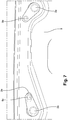
- the integrated indexing finger 5c extends to the assembly through an indexing orifice 2b, (visible in the bottom view of the figure 7 ), which is remote from the screw hole 2a of the screw 6.
- the integrated finger 5c is oriented perpendicular to the tab 5a, in the opposite direction of the foot 1b, that is to say towards the body reinforcement 2.
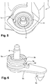
- the part plane 5b of the collar integrates an indexing protrusion 5d on the elastomeric pad 3. This protrusion, or pin, is visible on the figure 5 .
- the damping buffer 3 has at least one indexing cutout 3a on the protrusion 5d of the collar.
- the buffer 3 is itself indexed on the housing 1 by its cutout 3b, which cooperates with the lug 1d of the housing (cf. figure 5 ). With this double indexing, the tab 5b of the collar is automatically oriented towards the indexing orifice 2b of the body reinforcement, for example in the arrangement illustrated by the bottom view of the figure 7 .
- the mounting of the housing is performed without requiring the adjustment in position of the indexing fingers 5c by the operator.
- the four fastening systems (comprising a metal collar 5 and an elastomeric buffer 3 inserted between the collar and the foot), are presented on the screw heads 6a, oriented in this example upwards, before screwing .
- the fixing feet 1a, 1b of the housing are received on the screws 6, which are oriented at the top, through fixing orifices 2a of the structural element.
- the indexing fingers 5) integrated in the fixing systems of the housing are received in indexing holes 2b of the structural element 2, offset relative to the corresponding fixing holes. Two of them do not participate in the indexing, which is ensured, in accordance with the invention, by the other two.
- the housing is oriented the housing properly on the body, and well insulated.
- the housing can debate in a controlled manner on the cash reinforcement with damping buffers, without these movements are reported on its indexing means.
- the mounting can also be carried out in the case where the vehicle body is equipped with fixing nuts, which implies that the screws are oriented downwards, not upwards.
- the assembly is carried out on an inverted U-shaped box tunnel, or on a box reinforcement, attached to it.
Landscapes
- Engineering & Computer Science (AREA)
- Chemical & Material Sciences (AREA)
- Combustion & Propulsion (AREA)
- Transportation (AREA)
- Mechanical Engineering (AREA)
- Vibration Prevention Devices (AREA)
- Gear-Shifting Mechanisms (AREA)
- General Details Of Gearings (AREA)
Abstract
Description
- La présente invention concerne la fixation des boîtiers de commande de boîte de vitesses dans l'habitacle d'un véhicule, sur la caisse de celui-ci, ou sur un élément de structure, tel qu'un renfort de tunnel sur caisse.
- Plus précisément, elle a pour objet un système de fixation d'un boîtier sur un élément de structure, comportant un collet métallique de réception d'une vis de fixation au travers d'un orifice de fixation de l'élément de structure, qui comprend une partie cylindrique insérée dans un tampon amortisseur de vibrations logé à l'intérieur du boîtier.
- La présente invention a également pour objet un boîtier de commande de vitesses comportant au moins un pied de fixation sur un élément de structure de véhicule comportant un système de fixation.
- Elle a enfin pour objet un procédé de montage d'un boîtier, dont les pieds de fixation sont reçus sur des vis orientées vers le haut ou vers le bas, au travers d'orifices de fixation d'un élément de structure de véhicule.
- Les boîtiers de commande de vitesses montés dans l'habitacle, permettent de monter et de supporter le levier, ou sélecteur de vitesses, mis à disposition du conducteur, « au plancher », ou sur une console plus ou moins surélevée, à proximité de son siège.
- Pour des raisons de structure et d'architecture, la caisse forme souvent un tunnel central présentant globalement en coupe transversale une section en U inversé, entre les sièges gauche et droite du véhicule. Le tunnel est partie intégrante de la caisse, ou bien réalisé par un renfort de caisse rapporté sur celle-ci. Il offre généralement un espace suffisant pour loger un dispositif de commande de vitesses, incluant une embase de support et d'articulation du levier ou du sélecteur de vitesses, et certains des éléments de mécanisme assurant la liaison mécanique du levier avec la boîte. Le dispositif concerné participe à la commande des vitesses, en transformant les déplacements du levier, en déplacements fonctionnels, de câbles ou tringles de commande, actionnant les mécanismes internes de la boîte de vitesses.
- Les vibrations des trains roulants et du groupe motopropulseur remontent au travers du boîtier de commande, jusqu'au levier de vitesses. Elles sont relativement importantes, et nécessitent l'introduction d'éléments amortisseurs, par exemple du type « silent block », entre le boîtier et son support, renforts de caisse, ou caisse proprement dite du véhicule.
- Le boîtier de commande de vitesses requiert un positionnement précis sur la caisse pour garantir les jeux de fonctionnement et d'aspect entre la commande de boîte et la console centrale, la planche de bord ou tout autre élément d'habillage en proximité avec la commande. A cette condition, le levier peut assurer la commande effective des changements de vitesses avec la fiabilité requise par la transmission de ses mouvements, jusqu'aux mécanismes internes de la boîte. Dans le cas où des éléments de filtration vibratoires sont introduits entre la caisse et le boîtier, il n'est pas possible d'indexer le boîtier par l'intermédiaire de formes issues du boîtier, du fait des mouvements relatifs entre la caisse et le boîtier. Il n'est pas non plus possible d'indexer le boîtier sur des vis de fixation, qui introduiraient alors trop de dispersion dans sa mise en place.
- Selon une disposition courante, on équipe souvent le boîtier de commande, de tampons amortisseurs, au droit de ses fixations. Les tampons isolent le boîtier, des vibrations de la caisse. Le boîtier se déplace par rapport à la caisse, du fait des remontées vibratoires, et des déplacements qui lui sont imposés sous l'effort de passage des vitesses. Si les indexeurs sont intégrés au boîtier, l'indexage est par principe antinomique avec le besoin d'isolation entre le boîtier et la caisse. Enfin, dans le cas fréquent, où le boîtier est en matière plastique, avec des indexeurs issus de la même matière, ces derniers sont trop fragiles pour absorber sans risque de casse, les efforts transitant par le boîtier.
- Pour corriger ce problème, on a déjà envisagé de renoncer à toute forme d'indexage. La suppression des indexeurs interdit la mise en géométrie du boîtier de commande, par rapport à la caisse. Si les tampons amortisseurs sont dimensionnés pour garantir le montage dans tous les cas, malgré la dispersion de position des vis sur la caisse (par exemple avec un jeu d'environ 1.6mm), il est impossible de venir indexer le boîtier de commande sur les vis.
- La présente invention vise à assurer l'indexage d'un boîtier de commande sur un élément de structure, sans perturber l'isolation vibratoire du boîtier.
- Dans ce but, elle propose que la partie cylindrique du boîtier se prolonge radialement à sa base par une partie plane d'appui sur l'élément de structure, jusqu'à un doigt d'indexage sur l'élément de structure, intégré à son extrémité.
- De préférence, la partie plane du collet intègre une excroissance d'indexage sur le tampon élastomère.
- Le boîtier de commande proposé, comporte au moins un système de fixation, sur un élément de structure de véhicule.
- Lors du montage du boîtier sur l'élément de structure, les doigts d'indexage, qui sont intégrés aux systèmes de fixation du boîtier, sont reçus dans des orifices d'indexage de l'élément de structure ; ces orifices sont déportés par rapport aux orifices de fixation correspondants.
- D'autres caractéristiques et avantages de l'invention seront mieux compris à la lecture de la description suivante d'un mode de réalisation non limitatif de celle-ci, en se reportant aux dessins annexés sur lesquels :
- les
figures 1 et 2 illustrent un montage connu, - les
figures 3 et 4 se rapportent à l'invention, - la
figure 5 est une vue de dessus d'un pied de fixation du boîtier, - la
figure 6 un agrandissement du système de fixation proposé, et - la
figure 7 une vue de dessous de l'élément de structure après montage du boîtier. - La
figure 1 montre en partie un boîtier de commande de vitesses 1 de véhicule, monté sur un renfort de caisse 2 longitudinal. Le boîtier est réalisé par exemple en matière plastique. Il s'étend à l'intérieur de l'habitacle, et supporte un levier (ou sélecteur) de vitesses (non représenté) à disposition du conducteur « au plancher », sur son poste de conduite. Il renferme aussi des éléments de liaison (également non représentés), du levier avec la « commande externe » de la boîte de vitesses. - Sur le schéma, on voit apparaître entre le boîtier 1 et l'élément 2 : deux tampons amortisseurs 3, de préférence en élastomère, le boîtier, ainsi que deux doigts d'indexage 4 issus du boîtier 1. L'un deux traverse sans jeu un orifice de fixation 2a du renfort de caisse. L'autre s'étend au travers d'un orifice d'indexage allongé 2b dans la direction longitudinale du renfort, facilitant le montage du boîtier sur celui-ci.
- Aux pieds du boîtier 1, entre les tampons 3 et le renfort de caisse 2, on distingue le bord d'un collet 5, de préférence métallique, dont la forme est révélée par la coupe de la
figure 2 . Cette coupe met en évidence la structure d'un des quatre systèmes de fixation du boîtier sur le renfort. La coupe passe par le boîtier de commande 1, la caisse 2 le collet métallique 5 et une vis de fixation 6. Les vis 6 sont introduites initialement par le dessous sur le renfort de caisse, en attente des pieds 1a du boîtier. Lors du montage, le boîtier 1 est muni, à chacun de ses pieds 1a, d'un système de fixation 10, composé du collet métallique 5 et du tampon 3 élastomère inséré entre le collet et le pied 1a. Chaque pied est présenté sur une tête de vis 6a, orientée vers le haut. On procède ensuite au vissage. Les problèmes rencontrés avec ce type d'installation viennent de l'antinomie entre le blocage en position des doigts d'indexage 4 sur le renfort de caisse, et le débattement du boîtier. Le débattement, qui est permis par les tampons antivibratoires 3, est déconnecté des doigts d'indexage 4. Cette déconnexion peut conduire à la casse des doigts d'indexage, en cas de forte sollicitation mécanique ou vibratoire du boîtier. - En résumé, ce système de fixation, comprend un collet métallique 5 de réception d'une vis de fixation 6 au travers d'un orifice de fixation 1c de l'élément de structure, comportant une partie cylindrique 5a insérée dans un tampon amortisseur de vibrations 3 logé à l'intérieur du boîtier 1. L'évolution proposée par l'invention porte sur ce système de fixation du boîtier sur l'élément de structure 2, au niveau de ses pieds 1a. Elle est illustrée par les
figures 3 à 6 . - La
figure 3 montre en vue de dessous un boîtier de commande de vitesses 1, avec quatre pieds de fixation sur un élément de structure du véhicule 2, tel qu'un renfort de caisse (non représenté). Chaque pied porte un système de fixation. Le boîtier proposé, comporte au moins un système de fixation conforme à l'invention, de préférence deux, sur un élément de structure 2 de véhicule. Le boîtier présente au moins un, de préférence deux, pieds de fixation 1b sur un élément de structure de véhicule comportant un système de fixation conforme à l'invention. - Deux des quatre systèmes de fixation du boîtier, sont semblables à la
figure 2 . Les deux autres, sont conformes à l'invention. Le collet métallique 5 introduit dans le tampon amortisseur 3 est différent. Il présente comme précédemment une partie cylindrique 5a autour de laquelle est inséré le tampon 3. Toutefois, la partie 5a cylindrique du boîtier se prolonge radialement à sa base par une partie plane d'appui 5b sur l'élément de structure 2 jusqu'à un doigt d'indexage 5c sur l'élément de structure 2, intégré à son extrémité. - Conformément à l'invention, les doigts d'indexage intégrés 5c, portés par les collets métalliques, sont dissociés du boîtier de commande. Le doigt d'indexage intégré 5c s'étend au montage au travers d'un orifice d'indexage 2b, (visible sur la vue de dessous de la
figure 7 ), qui est distant du trou de vissage 2a de la vis 6. Le doigt intégré 5c est orienté perpendiculairement à la patte 5a, en direction opposée du pied 1b, c'est-à-dire vers le renfort de caisse 2. La partie plane 5b du collet, intègre une excroissance 5d d'indexage sur le tampon élastomère 3. Cet excroissance, ou ergot, est visible sur lafigure 5 . Elle coopère avec une des encoches 3a découpées dans l'élastomère du tampon 3, visible sur lafigure 6 : le tampon d'amortissement 3 présente au moins une découpe d'indexation 3a sur l'excroissance 5d du collet. Le tampon 3 est lui-même indexé sur le boîtier 1 par sa découpe 3b, qui coopère avec l'ergot 1d du boîtier (cf.figure 5 ). Grâce à ce double indexage, la patte 5b du collet est orientée automatiquement en direction de l'orifice d'indexage 2b du renfort de caisse, par exemple dans la disposition illustrée par la vue de dessous de lafigure 7 . - Le montage du boîtier s'effectue sans nécessiter l'ajustement en position des doigts d'indexage 5c par l'opérateur. Comme précédemment, les quatre systèmes de fixation (comprenant un collet métallique 5 et un tampon 3 élastomère inséré entre le collet et le pied), sont présentés sur les têtes de vis 6a, orientées dans cet exemple vers le haut, avant de procéder au vissage. Les pieds de fixation 1a, 1b du boîtier sont reçus sur les vis 6 orientées ici le haut, au travers d'orifices de fixation 2a de l'élément de structure. Les doigts d'indexage 5) intégrés aux systèmes de fixation du boîtier sont reçus dans des orifices d'indexage 2b de l'élément de structure 2, déportés par rapport aux orifices de fixation correspondants. Deux d'entre eux ne participent pas à l'indexage, qui est assuré, conformément à l'invention, par les deux autres. Le boîtier est orienté le boîtier correctement sur la caisse, et bien isolé. Lors de remontées vibratoires de la caisse, ou en cas d'efforts importants imposés par le levier de vitesses, le boîtier peut débattre de manière contrôlée sur le renfort de caisse grâce aux tampons d'amortissement, sans que ces mouvements soient reportés sur ses moyens d'indexage.
- Le montage peut également s'effectuer dans le cas où la caisse du véhicule est équipée d'écrous de fixation, ce qui implique que les vis soient orientées vers le bas, et non vers le haut.
- Le montage s'effectue sur un tunnel de caisse en U inversé, ou sur un renfort de caisse, rapporté sur celle-ci.
Claims (11)
- Système de fixation, d'un boîtier (1) sur un élément de structure (2), comportant un collet métallique (5) de réception d'une vis de fixation (6) au travers d'un orifice de fixation (1c) de l'élément de structure, qui comprend une partie cylindrique (5a) insérée dans un tampon amortisseur de vibrations (3) logé à l'intérieur du boîtier (1), caractérisé en ce que la partie (5a) cylindrique du boîtier (1) se prolonge radialement à sa base par une partie plane d'appui (5b) sur l'élément de structure (2) jusqu'à un doigt d'indexage (5c) sur l'élément de structure (2), intégré à son extrémité.
- Système de fixation selon la revendication 1, caractérisé en ce que la partie plane (5b) du collet intègre une excroissance (5d) d'indexage sur le tampon élastomère (3).
- Système de fixation selon la revendication 2, caractérisé en ce que le tampon d'amortissement (3) présente au moins une découpe d'indexation (3a) sur l'excroissance (5d) du collet (5) .
- Système de fixation selon la revendication 2 ou 3, caractérisé en ce que le tampon d'amortissement (3) présente au moins une découpe d'indexation (3b) sur le boîtier (1).
- Boîtier de commande de vitesses, caractérisé en ce qu'il comporte au moins un système de fixation, conforme à l'une des revendications 1 à 4, sur un élément de structure (2) de véhicule.
- Boîtier de commande de vitesses selon la revendication 5, caractérisé en ce qu'il présente au moins un pied de fixation (1b) sur un élément de structure de véhicule comportant un système de fixation conforme à l'une des revendications 1 à 4.
- Boîtier de commande de vitesses selon la revendication 5 ou 6, caractérisé en ce qu'il comporte au moins deux systèmes de fixation conformes à l'une des revendications 1 à 4.
- Procédé de montage d'un boîtier de commande de vitesses conforme à la revendication 6 ou 7, dont les pieds de fixation (1a, 1b) sont reçus sur des vis (6) au travers d'orifices de fixation (2a) d'un élément de structure (2) de véhicule, caractérisé en ce que les doigts d'indexage (5c) intégrés aux systèmes de fixation du boîtier sont reçus dans des orifices d'indexage (2b) de l'élément de structure (2), déportés par rapport aux orifices de fixation (2a) correspondants.
- Procédé de montage d'un boîtier de commande de vitesses selon la revendication 8, caractérisé en ce que les pieds de fixation (1a, 1b) sont reçus sur des vis (6) orientées vers le haut.
- Procédé de montage d'un boîtier selon la revendication 8 ou 9, caractérisé en ce qu'il d'effectue sur un tunnel de caisse en U inversé.
- Procédé de montage selon la revendication 8 ou 9, caractérisé en ce qu'il s'effectue sur un renfort de caisse.
Applications Claiming Priority (1)
| Application Number | Priority Date | Filing Date | Title |
|---|---|---|---|
| FR1770179A FR3063275B1 (fr) | 2017-02-24 | 2017-02-24 | Systeme de fixation d’un boitier sur un element de structure, boitier de commande, et procede de montage correspondant |
Publications (2)
| Publication Number | Publication Date |
|---|---|
| EP3369601A1 true EP3369601A1 (fr) | 2018-09-05 |
| EP3369601B1 EP3369601B1 (fr) | 2020-03-04 |
Family
ID=59974709
Family Applications (1)
| Application Number | Title | Priority Date | Filing Date |
|---|---|---|---|
| EP18153012.2A Active EP3369601B1 (fr) | 2017-02-24 | 2018-01-23 | Système de fixation d'un boîtier sur un élément de structure, boîtier de commande, et procédé de montage correspondant |
Country Status (2)
| Country | Link |
|---|---|
| EP (1) | EP3369601B1 (fr) |
| FR (1) | FR3063275B1 (fr) |
Citations (4)
| Publication number | Priority date | Publication date | Assignee | Title |
|---|---|---|---|---|
| JPS4518805Y1 (fr) * | 1967-02-24 | 1970-07-31 | ||
| US4306708A (en) * | 1979-05-14 | 1981-12-22 | Tennessee Bolt And Screw Co., Inc. | Means for establishing a support post for a grommet |
| US4711135A (en) * | 1984-12-10 | 1987-12-08 | Toyota Jidosha Kabushiki Kaisha | Vibration damping structure of shift lever retainer |
| EP1375973A2 (fr) * | 2002-06-28 | 2004-01-02 | Fuji Jukogyo Kabushiki Kaisha | Structure d'assemblage de levier de vitesses sur carrosserie de véhicule |
-
2017
- 2017-02-24 FR FR1770179A patent/FR3063275B1/fr not_active Expired - Fee Related
-
2018
- 2018-01-23 EP EP18153012.2A patent/EP3369601B1/fr active Active
Patent Citations (4)
| Publication number | Priority date | Publication date | Assignee | Title |
|---|---|---|---|---|
| JPS4518805Y1 (fr) * | 1967-02-24 | 1970-07-31 | ||
| US4306708A (en) * | 1979-05-14 | 1981-12-22 | Tennessee Bolt And Screw Co., Inc. | Means for establishing a support post for a grommet |
| US4711135A (en) * | 1984-12-10 | 1987-12-08 | Toyota Jidosha Kabushiki Kaisha | Vibration damping structure of shift lever retainer |
| EP1375973A2 (fr) * | 2002-06-28 | 2004-01-02 | Fuji Jukogyo Kabushiki Kaisha | Structure d'assemblage de levier de vitesses sur carrosserie de véhicule |
Also Published As
| Publication number | Publication date |
|---|---|
| FR3063275B1 (fr) | 2019-06-07 |
| EP3369601B1 (fr) | 2020-03-04 |
| FR3063275A1 (fr) | 2018-08-31 |
Similar Documents
| Publication | Publication Date | Title |
|---|---|---|
| JP6908740B2 (ja) | 車両操舵輪へのエアバッグモジュールの揺動方式による取り付けのための結合装置 | |
| US10023221B2 (en) | Steering wheel structure | |
| EP2749448B1 (fr) | Dispositif de manchon pour appuie-tête | |
| EP3545216B1 (fr) | Dispositif de déverrouillage destiné à déverrouiller un frein de stationnement d'un véhicule et procédé permettant de faire fonctionner un dispositif de déverrouillage | |
| FR2928613A1 (fr) | Procede de montage d'une commande de boite de vitesse en position haute pour vehicule, et dispositif pour la mise en oeuvre d'un tel procede. | |
| CN103821923B (zh) | 用于换档缆索的调节结构 | |
| EP1312838A2 (fr) | Câble de commande d'une boíte de vitesses automatique de véhicule | |
| KR101362461B1 (ko) | 자동차용 마운트 | |
| FR3063275B1 (fr) | Systeme de fixation d’un boitier sur un element de structure, boitier de commande, et procede de montage correspondant | |
| RU2591116C2 (ru) | Приводное устройство коробки передач с защелкивающимся инерционным балансиром | |
| US20100212447A1 (en) | Shifting device for a vehicle transmission | |
| JP2006300110A (ja) | 車両搭載対象物の支持装置 | |
| US20160153555A1 (en) | Pivoting assembly mounted on a motor vehicle gearbox for shifting and selecting gears | |
| DE102015219319B4 (de) | Pendelstütze zur Bewerkstelligung der Abstützung eines Aggregates in einem Kraftfahrzeug | |
| KR100534876B1 (ko) | 변속 케이블 고정용 클립 댐퍼 구조물 | |
| KR950006973Y1 (ko) | 자동차용 자동 변속기 작동케이블 | |
| US20040194568A1 (en) | Shift lever vibration isolator | |
| KR101885022B1 (ko) | 자동차의 조향컬럼 | |
| FR3050154A1 (fr) | Element d'insonorisation pour vehicule automobile | |
| US2532170A (en) | Steering column gearshift clutch construction | |
| JP2010236559A (ja) | 配管の車体への取付構造 | |
| KR100207051B1 (ko) | 6속 수동변속기의 셀렉트장치 | |
| KR100210420B1 (ko) | 자동차용 자동변속기 레버의 진동 절연구조 | |
| FR2547398A1 (fr) | Mecanisme pour regler un organe commandant un ecoulement d'air notamment dans un vehicule automobile | |
| US20070193393A1 (en) | Push rod bracket assembly for use with a brake pedal assembly and method of assembly thereto |
Legal Events
| Date | Code | Title | Description |
|---|---|---|---|
| PUAI | Public reference made under article 153(3) epc to a published international application that has entered the european phase |
Free format text: ORIGINAL CODE: 0009012 |
|
| STAA | Information on the status of an ep patent application or granted ep patent |
Free format text: STATUS: THE APPLICATION HAS BEEN PUBLISHED |
|
| AK | Designated contracting states |
Kind code of ref document: A1 Designated state(s): AL AT BE BG CH CY CZ DE DK EE ES FI FR GB GR HR HU IE IS IT LI LT LU LV MC MK MT NL NO PL PT RO RS SE SI SK SM TR |
|
| AX | Request for extension of the european patent |
Extension state: BA ME |
|
| STAA | Information on the status of an ep patent application or granted ep patent |
Free format text: STATUS: REQUEST FOR EXAMINATION WAS MADE |
|
| 17P | Request for examination filed |
Effective date: 20190305 |
|
| RBV | Designated contracting states (corrected) |
Designated state(s): AL AT BE BG CH CY CZ DE DK EE ES FI FR GB GR HR HU IE IS IT LI LT LU LV MC MK MT NL NO PL PT RO RS SE SI SK SM TR |
|
| RIC1 | Information provided on ipc code assigned before grant |
Ipc: B60K 20/04 20060101ALI20190718BHEP Ipc: B60K 20/02 20060101AFI20190718BHEP Ipc: B60K 20/08 20060101ALI20190718BHEP |
|
| GRAP | Despatch of communication of intention to grant a patent |
Free format text: ORIGINAL CODE: EPIDOSNIGR1 |
|
| STAA | Information on the status of an ep patent application or granted ep patent |
Free format text: STATUS: GRANT OF PATENT IS INTENDED |
|
| INTG | Intention to grant announced |
Effective date: 20190917 |
|
| GRAS | Grant fee paid |
Free format text: ORIGINAL CODE: EPIDOSNIGR3 |
|
| GRAA | (expected) grant |
Free format text: ORIGINAL CODE: 0009210 |
|
| STAA | Information on the status of an ep patent application or granted ep patent |
Free format text: STATUS: THE PATENT HAS BEEN GRANTED |
|
| AK | Designated contracting states |
Kind code of ref document: B1 Designated state(s): AL AT BE BG CH CY CZ DE DK EE ES FI FR GB GR HR HU IE IS IT LI LT LU LV MC MK MT NL NO PL PT RO RS SE SI SK SM TR |
|
| REG | Reference to a national code |
Ref country code: GB Ref legal event code: FG4D Free format text: NOT ENGLISH |
|
| REG | Reference to a national code |
Ref country code: CH Ref legal event code: EP |
|
| REG | Reference to a national code |
Ref country code: AT Ref legal event code: REF Ref document number: 1239978 Country of ref document: AT Kind code of ref document: T Effective date: 20200315 |
|
| REG | Reference to a national code |
Ref country code: DE Ref legal event code: R096 Ref document number: 602018002745 Country of ref document: DE |
|
| REG | Reference to a national code |
Ref country code: IE Ref legal event code: FG4D Free format text: LANGUAGE OF EP DOCUMENT: FRENCH |
|
| PG25 | Lapsed in a contracting state [announced via postgrant information from national office to epo] |
Ref country code: NO Free format text: LAPSE BECAUSE OF FAILURE TO SUBMIT A TRANSLATION OF THE DESCRIPTION OR TO PAY THE FEE WITHIN THE PRESCRIBED TIME-LIMIT Effective date: 20200604 Ref country code: FI Free format text: LAPSE BECAUSE OF FAILURE TO SUBMIT A TRANSLATION OF THE DESCRIPTION OR TO PAY THE FEE WITHIN THE PRESCRIBED TIME-LIMIT Effective date: 20200304 Ref country code: RS Free format text: LAPSE BECAUSE OF FAILURE TO SUBMIT A TRANSLATION OF THE DESCRIPTION OR TO PAY THE FEE WITHIN THE PRESCRIBED TIME-LIMIT Effective date: 20200304 |
|
| REG | Reference to a national code |
Ref country code: NL Ref legal event code: MP Effective date: 20200304 |
|
| PG25 | Lapsed in a contracting state [announced via postgrant information from national office to epo] |
Ref country code: SE Free format text: LAPSE BECAUSE OF FAILURE TO SUBMIT A TRANSLATION OF THE DESCRIPTION OR TO PAY THE FEE WITHIN THE PRESCRIBED TIME-LIMIT Effective date: 20200304 Ref country code: LV Free format text: LAPSE BECAUSE OF FAILURE TO SUBMIT A TRANSLATION OF THE DESCRIPTION OR TO PAY THE FEE WITHIN THE PRESCRIBED TIME-LIMIT Effective date: 20200304 Ref country code: HR Free format text: LAPSE BECAUSE OF FAILURE TO SUBMIT A TRANSLATION OF THE DESCRIPTION OR TO PAY THE FEE WITHIN THE PRESCRIBED TIME-LIMIT Effective date: 20200304 Ref country code: BG Free format text: LAPSE BECAUSE OF FAILURE TO SUBMIT A TRANSLATION OF THE DESCRIPTION OR TO PAY THE FEE WITHIN THE PRESCRIBED TIME-LIMIT Effective date: 20200604 Ref country code: GR Free format text: LAPSE BECAUSE OF FAILURE TO SUBMIT A TRANSLATION OF THE DESCRIPTION OR TO PAY THE FEE WITHIN THE PRESCRIBED TIME-LIMIT Effective date: 20200605 |
|
| REG | Reference to a national code |
Ref country code: LT Ref legal event code: MG4D |
|
| PG25 | Lapsed in a contracting state [announced via postgrant information from national office to epo] |
Ref country code: NL Free format text: LAPSE BECAUSE OF FAILURE TO SUBMIT A TRANSLATION OF THE DESCRIPTION OR TO PAY THE FEE WITHIN THE PRESCRIBED TIME-LIMIT Effective date: 20200304 |
|
| PG25 | Lapsed in a contracting state [announced via postgrant information from national office to epo] |
Ref country code: ES Free format text: LAPSE BECAUSE OF FAILURE TO SUBMIT A TRANSLATION OF THE DESCRIPTION OR TO PAY THE FEE WITHIN THE PRESCRIBED TIME-LIMIT Effective date: 20200304 Ref country code: RO Free format text: LAPSE BECAUSE OF FAILURE TO SUBMIT A TRANSLATION OF THE DESCRIPTION OR TO PAY THE FEE WITHIN THE PRESCRIBED TIME-LIMIT Effective date: 20200304 Ref country code: IS Free format text: LAPSE BECAUSE OF FAILURE TO SUBMIT A TRANSLATION OF THE DESCRIPTION OR TO PAY THE FEE WITHIN THE PRESCRIBED TIME-LIMIT Effective date: 20200704 Ref country code: CZ Free format text: LAPSE BECAUSE OF FAILURE TO SUBMIT A TRANSLATION OF THE DESCRIPTION OR TO PAY THE FEE WITHIN THE PRESCRIBED TIME-LIMIT Effective date: 20200304 Ref country code: PT Free format text: LAPSE BECAUSE OF FAILURE TO SUBMIT A TRANSLATION OF THE DESCRIPTION OR TO PAY THE FEE WITHIN THE PRESCRIBED TIME-LIMIT Effective date: 20200729 Ref country code: SK Free format text: LAPSE BECAUSE OF FAILURE TO SUBMIT A TRANSLATION OF THE DESCRIPTION OR TO PAY THE FEE WITHIN THE PRESCRIBED TIME-LIMIT Effective date: 20200304 Ref country code: EE Free format text: LAPSE BECAUSE OF FAILURE TO SUBMIT A TRANSLATION OF THE DESCRIPTION OR TO PAY THE FEE WITHIN THE PRESCRIBED TIME-LIMIT Effective date: 20200304 Ref country code: LT Free format text: LAPSE BECAUSE OF FAILURE TO SUBMIT A TRANSLATION OF THE DESCRIPTION OR TO PAY THE FEE WITHIN THE PRESCRIBED TIME-LIMIT Effective date: 20200304 Ref country code: SM Free format text: LAPSE BECAUSE OF FAILURE TO SUBMIT A TRANSLATION OF THE DESCRIPTION OR TO PAY THE FEE WITHIN THE PRESCRIBED TIME-LIMIT Effective date: 20200304 |
|
| REG | Reference to a national code |
Ref country code: AT Ref legal event code: MK05 Ref document number: 1239978 Country of ref document: AT Kind code of ref document: T Effective date: 20200304 |
|
| REG | Reference to a national code |
Ref country code: DE Ref legal event code: R097 Ref document number: 602018002745 Country of ref document: DE |
|
| PLBE | No opposition filed within time limit |
Free format text: ORIGINAL CODE: 0009261 |
|
| STAA | Information on the status of an ep patent application or granted ep patent |
Free format text: STATUS: NO OPPOSITION FILED WITHIN TIME LIMIT |
|
| PG25 | Lapsed in a contracting state [announced via postgrant information from national office to epo] |
Ref country code: DK Free format text: LAPSE BECAUSE OF FAILURE TO SUBMIT A TRANSLATION OF THE DESCRIPTION OR TO PAY THE FEE WITHIN THE PRESCRIBED TIME-LIMIT Effective date: 20200304 Ref country code: IT Free format text: LAPSE BECAUSE OF FAILURE TO SUBMIT A TRANSLATION OF THE DESCRIPTION OR TO PAY THE FEE WITHIN THE PRESCRIBED TIME-LIMIT Effective date: 20200304 Ref country code: AT Free format text: LAPSE BECAUSE OF FAILURE TO SUBMIT A TRANSLATION OF THE DESCRIPTION OR TO PAY THE FEE WITHIN THE PRESCRIBED TIME-LIMIT Effective date: 20200304 |
|
| 26N | No opposition filed |
Effective date: 20201207 |
|
| PG25 | Lapsed in a contracting state [announced via postgrant information from national office to epo] |
Ref country code: PL Free format text: LAPSE BECAUSE OF FAILURE TO SUBMIT A TRANSLATION OF THE DESCRIPTION OR TO PAY THE FEE WITHIN THE PRESCRIBED TIME-LIMIT Effective date: 20200304 Ref country code: SI Free format text: LAPSE BECAUSE OF FAILURE TO SUBMIT A TRANSLATION OF THE DESCRIPTION OR TO PAY THE FEE WITHIN THE PRESCRIBED TIME-LIMIT Effective date: 20200304 |
|
| PG25 | Lapsed in a contracting state [announced via postgrant information from national office to epo] |
Ref country code: MC Free format text: LAPSE BECAUSE OF FAILURE TO SUBMIT A TRANSLATION OF THE DESCRIPTION OR TO PAY THE FEE WITHIN THE PRESCRIBED TIME-LIMIT Effective date: 20200304 |
|
| REG | Reference to a national code |
Ref country code: CH Ref legal event code: PL |
|
| PG25 | Lapsed in a contracting state [announced via postgrant information from national office to epo] |
Ref country code: LU Free format text: LAPSE BECAUSE OF NON-PAYMENT OF DUE FEES Effective date: 20210123 |
|
| REG | Reference to a national code |
Ref country code: BE Ref legal event code: MM Effective date: 20210131 |
|
| PG25 | Lapsed in a contracting state [announced via postgrant information from national office to epo] |
Ref country code: LI Free format text: LAPSE BECAUSE OF NON-PAYMENT OF DUE FEES Effective date: 20210131 Ref country code: CH Free format text: LAPSE BECAUSE OF NON-PAYMENT OF DUE FEES Effective date: 20210131 |
|
| PG25 | Lapsed in a contracting state [announced via postgrant information from national office to epo] |
Ref country code: IE Free format text: LAPSE BECAUSE OF NON-PAYMENT OF DUE FEES Effective date: 20210123 |
|
| PG25 | Lapsed in a contracting state [announced via postgrant information from national office to epo] |
Ref country code: BE Free format text: LAPSE BECAUSE OF NON-PAYMENT OF DUE FEES Effective date: 20210131 |
|
| GBPC | Gb: european patent ceased through non-payment of renewal fee |
Effective date: 20220123 |
|
| PG25 | Lapsed in a contracting state [announced via postgrant information from national office to epo] |
Ref country code: GB Free format text: LAPSE BECAUSE OF NON-PAYMENT OF DUE FEES Effective date: 20220123 |
|
| PG25 | Lapsed in a contracting state [announced via postgrant information from national office to epo] |
Ref country code: CY Free format text: LAPSE BECAUSE OF FAILURE TO SUBMIT A TRANSLATION OF THE DESCRIPTION OR TO PAY THE FEE WITHIN THE PRESCRIBED TIME-LIMIT Effective date: 20200304 |
|
| P01 | Opt-out of the competence of the unified patent court (upc) registered |
Effective date: 20230608 |
|
| PG25 | Lapsed in a contracting state [announced via postgrant information from national office to epo] |
Ref country code: HU Free format text: LAPSE BECAUSE OF FAILURE TO SUBMIT A TRANSLATION OF THE DESCRIPTION OR TO PAY THE FEE WITHIN THE PRESCRIBED TIME-LIMIT; INVALID AB INITIO Effective date: 20180123 |
|
| PG25 | Lapsed in a contracting state [announced via postgrant information from national office to epo] |
Ref country code: MK Free format text: LAPSE BECAUSE OF FAILURE TO SUBMIT A TRANSLATION OF THE DESCRIPTION OR TO PAY THE FEE WITHIN THE PRESCRIBED TIME-LIMIT Effective date: 20200304 |
|
| PG25 | Lapsed in a contracting state [announced via postgrant information from national office to epo] |
Ref country code: TR Free format text: LAPSE BECAUSE OF FAILURE TO SUBMIT A TRANSLATION OF THE DESCRIPTION OR TO PAY THE FEE WITHIN THE PRESCRIBED TIME-LIMIT Effective date: 20200304 |
|
| PG25 | Lapsed in a contracting state [announced via postgrant information from national office to epo] |
Ref country code: MT Free format text: LAPSE BECAUSE OF FAILURE TO SUBMIT A TRANSLATION OF THE DESCRIPTION OR TO PAY THE FEE WITHIN THE PRESCRIBED TIME-LIMIT Effective date: 20200304 |
|
| PGFP | Annual fee paid to national office [announced via postgrant information from national office to epo] |
Ref country code: DE Payment date: 20260121 Year of fee payment: 9 |
|
| PGFP | Annual fee paid to national office [announced via postgrant information from national office to epo] |
Ref country code: FR Payment date: 20260123 Year of fee payment: 9 |