EP3369583A1 - Printer - Google Patents
Printer Download PDFInfo
- Publication number
- EP3369583A1 EP3369583A1 EP18153237.5A EP18153237A EP3369583A1 EP 3369583 A1 EP3369583 A1 EP 3369583A1 EP 18153237 A EP18153237 A EP 18153237A EP 3369583 A1 EP3369583 A1 EP 3369583A1
- Authority
- EP
- European Patent Office
- Prior art keywords
- main body
- body cover
- roll paper
- cover
- printer
- Prior art date
- Legal status (The legal status is an assumption and is not a legal conclusion. Google has not performed a legal analysis and makes no representation as to the accuracy of the status listed.)
- Granted
Links
Images



Classifications
-
- B—PERFORMING OPERATIONS; TRANSPORTING
- B41—PRINTING; LINING MACHINES; TYPEWRITERS; STAMPS
- B41J—TYPEWRITERS; SELECTIVE PRINTING MECHANISMS, i.e. MECHANISMS PRINTING OTHERWISE THAN FROM A FORME; CORRECTION OF TYPOGRAPHICAL ERRORS
- B41J29/00—Details of, or accessories for, typewriters or selective printing mechanisms not otherwise provided for
- B41J29/02—Framework
-
- B—PERFORMING OPERATIONS; TRANSPORTING
- B41—PRINTING; LINING MACHINES; TYPEWRITERS; STAMPS
- B41J—TYPEWRITERS; SELECTIVE PRINTING MECHANISMS, i.e. MECHANISMS PRINTING OTHERWISE THAN FROM A FORME; CORRECTION OF TYPOGRAPHICAL ERRORS
- B41J29/00—Details of, or accessories for, typewriters or selective printing mechanisms not otherwise provided for
- B41J29/12—Guards, shields or dust excluders
- B41J29/13—Cases or covers
-
- B—PERFORMING OPERATIONS; TRANSPORTING
- B41—PRINTING; LINING MACHINES; TYPEWRITERS; STAMPS
- B41J—TYPEWRITERS; SELECTIVE PRINTING MECHANISMS, i.e. MECHANISMS PRINTING OTHERWISE THAN FROM A FORME; CORRECTION OF TYPOGRAPHICAL ERRORS
- B41J15/00—Devices or arrangements of selective printing mechanisms, e.g. ink-jet printers or thermal printers, specially adapted for supporting or handling copy material in continuous form, e.g. webs
- B41J15/04—Supporting, feeding, or guiding devices; Mountings for web rolls or spindles
Definitions
- Embodiments described herein relate generally to a printer for printing on a roll paper.
- a technology for feeding a paper housed in a paper cassette and printing on the paper and then discharging the printed paper to a paper discharge tray. Further, with respect to the printer, a technology for feeding a roll paper housed in a main body cover and printing on the roll paper is known.
- a technology is also known for rotatably mounting an upper cover on a box-shaped main body. It is known to rotate the upper cover between opened and closed positions to exchange a roll paper. Further, as a printer using a roll paper, a technology for cutting off a roll paper discharged by an operator after printing and a technology for automatically cutting off a discharged roll paper by a cutter arranged in the printer is also known.
- a printer comprising:
- the main body cover preferably may have a rectangular protrusion arranged on an inner surface of an upper end of the back side.
- the main body cover preferably may have a rib-shaped protrusion arranged on an upper end of the back side.
- the main body cover preferably may have a protrusion arranged on an upper end of the back side having a peak extending from the back side.
- the upper cover preferably may have a recess arranged on an edge portion of the back side that interfaces with the protrusion.
- the gap preferably may comprise the recess.
- the upper cover preferably may be hingedly supported on the main body cover, and an upper surface thereof is flush with an upper end of the main body cover in a closed state.
- a printer comprising:
- the main body cover preferably may have a rectangular protrusion arranged on an inner surface of an upper end of the back side.
- the main body cover preferably may have a rib-shaped protrusion arranged on an upper end of the back side.
- the main body cover preferably may have a protrusion arranged on an upper end of the back side having a peak extending from the back side.
- the upper cover preferably may have a recess arranged on an edge portion of the back side that interfaces with the protrusion.
- the gap preferably may comprise the recess.
- a printer comprises a main body cover and an upper cover.
- the main body cover houses a roll paper, and an upper portion, the upper portion having an opening through which the roll paper can be loaded.
- the upper cover closes the opening of the main body cover, and has a gap in a direction in which at least one portion intersects with an axial center of the roll paper housed in the main body cover with the main body cover.
- a printer 1 according to a first embodiment is described with reference to Fig. 1 to Fig. 3 .
- Fig. 1 is a perspective view of the printer 1 according to the first embodiment
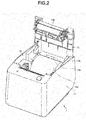
- Fig. 2 is a perspective view of the printer 1 and a state where an upper cover 12 is opened
- Fig. 3 is a view of the printer 1 and an example of a roll paper 100 discharged from a discharge port 15.
- the printer 1 includes a main body cover 11, the upper cover 12, and a printing mechanism 13.
- the printer 1 prints on the roll paper 100 housed in the main body cover 11, and then discharges the printed roll paper 100 from the discharge port 15.
- the roll paper 100 is formed by winding a belt-shaped paper into a roll shape on a winding core.
- a heat-sensitive paper is used, and then, the printer 1 is, for example, a thermal printer.
- a side at which the discharge port 15 is arranged with respect to the center of the printer 1 is described as a front side, and an opposite side to the side is described as a back side (rear side) below.
- a surface at a left near side is described as a front surface of the printer 1 below.
- the main body cover 11 is configured to have a rectangular box shape. An upper end of the main body cover 11 is configured to be opened, and the main body cover 11 houses the roll paper 100 loaded from the opening.
- the main body cover 11 has a front wall and a back wall along an axial direction of the roll paper 100 housed, and a pair of side walls along a direction orthogonal to the axial direction of the roll paper 100.
- the main body cover 11 has, on inner surfaces of the front wall, the back wall and the side walls, projections or ribs for mounting the printing mechanism 13.
- the inner surface of the upper end of the back wall of the main body cover 11 protrudes in a direction in which the roll paper 100 is discharged, and in which at least one portion of a range opposite to the discharged roll paper 100 intersects with the axial direction of the roll paper 100.
- the back wall of the main body cover 11 has a shape along the axial center of the roll paper 100.
- the inner surface of the upper end of the back wall of the main body cover 11 has a protrusion 11a that has a rectangular plate shape and protrudes toward the front wall at the center side.
- the main body cover 11 has the protrusion 11a at least in a portion of the range opposite to the roll paper 100 on the inner surface of the upper end of the main body cover 11 at the back side and in a direction orthogonal to the axial direction of the roll paper 100 housed in the main body cover 11.
- the upper cover 12 is disposed at the opening of the upper end of the main body cover 11 so as to be openable and closable.
- the upper cover 12 has a rotational shaft 12a rotatably supported on the main body cover 11.
- the rotational shaft 12a is located at a position lower than the upper end of the main body cover 11 and is rotatably supported on a pair of side walls separated from the back wall of the main body cover 11.
- the upper cover 12 is flush with the upper end of the main body cover 11 and blocks the opening of the main body cover 11 in the closed state.
- the upper cover 12 is separated from the inner surface of the upper end of the main body cover 11 at a predetermined gap in the closed state.
- a predetermined gap is provided between the main body cover 11 and the upper cover 12.
- the upper cover 12 has a recess 12b in which the projection 11a of the main body cover 11 is disposed in the closed state.
- the upper cover 12 constitutes the discharge port 15 of the roll paper 100 with the main body cover 11 in a gap 20 between the main body cover 11 and the upper cover 12 at a front side of the main body cover 11 in a closed state (shown in FIG. 1 ).
- the upper cover 12 opens the main body cover 11 such that the roll paper 100 can be loaded in the main body cover 11 in an open state of the main body cover 11.
- the upper cover 12 is rotatable until it becomes upright in the open state (i.e., orthogonal to the position of the upper cover 12 in the closed state), for example.
- the upper cover 12 may be in a forward inclined position with respect to the erect position, and may rotate further with respect to the erect position (i.e., to incline further than the erect position) .
- the opening degree of the upper cover 12 can be appropriately set as long as the roll paper 100 can be loaded in the main body cover 11 in the open state.
- the printing mechanism 13 sends the roll paper 100 housed in the main body cover 11 to the discharge port 15, and prints the roll paper 100.
- the printing mechanism 13 has a thermal head or platen roller 13a.
- the printing mechanism 13 is disposed inside the main body cover 11.
- the discharge port 15 is arranged between the main body cover 11 and the upper cover 12.
- the discharge port 15 is an opening extending along the axial center of the roll paper 100. Further, a cutter used by an operator to cut off the roll paper 100 is arranged in the discharge port 15.
- the printer 1 can prevent the situation where the roll paper 100 printed by the printing mechanism 13 and discharged from the discharge port 15 enters the gap 20 provided between the main body cover 11 and the upper cover 12 even if the roll paper 100 is curved and discharged to the rear as shown in Fig. 3 .
- the discharge port 15 of the printer 1 is arranged at a front side of the upper surface of the printer 1 along the axial center of the roll paper 100.
- the roll paper 100 is wound on the winding core. If the roll paper 100 is discharged from the discharge port 15, the roll paper 100 is curved at a predetermine curvature radius. Thus, the roll paper 100 discharged from the discharge port 15 forward and upward, and moves towards a direction opposite to the discharge port 15 of the printer 1 as shown in Fig. 3 . In the present embodiment, the roll paper 100 is discharged towards the back wall of the main body cover 11 and a rear edge portion of the upper cover 12.
- the roll paper 100 moves towards the gap 20 provided between the back wall of the main body cover 11 and the rear edge portion of the upper cover 12. If the roll paper 100 enters the gap, it is possible to enter between the roll paper 100 housed inside and wound, and the back wall.
- the protrusion 11a is included on the inner surface of the back wall of the main body cover 11, and the recess 12b is included in the rear edge portion of the upper cover 12, respectively.
- the gap 20 provided between the main body cover 11 and the upper cover 12 at a back side of the printer 1 at least one portion of the gap 20 at a position opposite to the roll paper 100 is not along the axial center of the roll paper 100.
- at least one portion thereof with respect to a width direction of the roll paper 100 serving as the axial center of the roll paper 100 intersects with the width direction.
- the printer 1 can prevent an abnormal of paper discharge or jamming of the roll paper 100 caused by the winding of the roll paper 100 since the roll paper 100 enters the inside of the main body cover 11.
- the gap 20 is provided between the main body cover 11 and the upper cover 12 during manufacture; however, it is also considered to prevent the roll paper 100 from entering the gap 20 by reducing a width of the gap.
- a thickness of the roll paper 100 is about 0.07 mm.
- the printer 1 of the present embodiment can prevent the roll paper 100 from entering the gap 20 with a simple structure in which the protrusion 11a and the recess 12b are arranged in the main body cover 11 and the upper cover 12.
- the roll paper 100 discharged can be prevented from entering the inside from the main body cover 11 and the upper cover 12.
- the present embodiment is not limited to the example described above.
- a printer configuration in which the protrusion 11a is arranged at least in a portion of a range opposite to the roll paper 100 of the inner surface of the upper end of the main body cover 11 is described; however, the present embodiment is not limited to this.
- the printer 1 may be configured such that a direction in which the gap 20 extends is not along the axial direction of the roll paper 100 such that an end portion of the roll paper 100 does not enter the gap 20 between the main body cover 11 and the upper cover 12 at the back side.
- the printer may be configured such that two rib-shaped protrusions 11a are arranged on the main body cover 11 in a range opposite to the roll paper 100, and recesses 12b having the same shape are arranged in the upper cover 12.
- the printer may be configured such that the entire inner surface of the upper end of the main body cover 11 comprises a protrusion 11a having a peak between two angled surfaces extending toward the discharge port 15 side, and a recess 12b having the same shape is arranged in the upper cover 12.
- the main body cover 11 may have a configuration in which each outer surface is constituted by a curved surface.
- the main body cover 11 may have a configuration in which a ridge section at the upper end side of the back wall is chamfered by an inclined surface. With such a configuration, the main body cover 11 can be guided such that the roll paper 100 discharged to the back wall side moves downward by a chamfering section.
Landscapes
- Accessory Devices And Overall Control Thereof (AREA)
- Handling Of Continuous Sheets Of Paper (AREA)
Abstract
Description
- Embodiments described herein relate generally to a printer for printing on a roll paper.
- As a printer for printing on paper sheets, a technology is known for feeding a paper housed in a paper cassette and printing on the paper and then discharging the printed paper to a paper discharge tray. Further, with respect to the printer, a technology for feeding a roll paper housed in a main body cover and printing on the roll paper is known.
- As the printer for printing on this roll paper, a technology is also known for rotatably mounting an upper cover on a box-shaped main body. It is known to rotate the upper cover between opened and closed positions to exchange a roll paper. Further, as a printer using a roll paper, a technology for cutting off a roll paper discharged by an operator after printing and a technology for automatically cutting off a discharged roll paper by a cutter arranged in the printer is also known.
- To solve the above-cited problems, there is provided a printer, comprising:
- a main body cover, wherein the main body cover houses a roll paper and an upper portion, the upper portion having an opening through which the roll paper can be loaded; and
- an upper cover configured to close the opening of the main body cover, the upper cover and the main body cover having a gap at a back side of the main body cover that is formed in a direction in which at least one portion thereof intersects with an axial center of the roll paper housed in the main body cover.
- In an exemplary embodiment, the main body cover preferably may have a rectangular protrusion arranged on an inner surface of an upper end of the back side.
- In another exemplary embodiment, the main body cover preferably may have a rib-shaped protrusion arranged on an upper end of the back side.
- In another exemplary embodiment, the main body cover preferably may have a protrusion arranged on an upper end of the back side having a peak extending from the back side.
- In the embodiments the upper cover preferably may have a recess arranged on an edge portion of the back side that interfaces with the protrusion.
- In the embodiments the gap preferably may comprise the recess.
- In the embodiments the upper cover preferably may be hingedly supported on the main body cover, and an upper surface thereof is flush with an upper end of the main body cover in a closed state.
- In yet another exemplary embodiment there is also provided a printer, comprising:
- a main body cover, wherein the main body cover houses a roll paper and an upper portion, the upper portion having an opening through which the roll paper can be loaded; and
- an upper cover hingedly connected to the main body cover that is configured to close the opening of the main body cover, the upper cover and the main body cover having a gap at a back side of the main body cover that is formed in a direction in which at least one portion thereof intersects with an axial center of the roll paper housed in the main body cover.
- In an exemplary embodiment the main body cover preferably may have a rectangular protrusion arranged on an inner surface of an upper end of the back side.
- In another exemplary embodiment the main body cover preferably may have a rib-shaped protrusion arranged on an upper end of the back side.
- In another exemplary embodiment the main body cover preferably may have a protrusion arranged on an upper end of the back side having a peak extending from the back side.
- In the embodiments the upper cover preferably may have a recess arranged on an edge portion of the back side that interfaces with the protrusion.
- In the embodiments the gap preferably may comprise the recess.
- The above and other objects, features and advantages of the present invention will be made apparent from the following description of the preferred embodiments, given as non-limiting examples, with reference to the accompanying drawings, in which:
-
Fig. 1 is a perspective view of a printer according to a first embodiment; -
Fig. 2 is a perspective view of the same printer with an upper cover opened; -
Fig. 3 is a side view of the same printer; -
Fig. 4 is a plan view of a printer according to a second embodiment; and -
Fig. 5 is a plan view of a printer according to a third embodiment. - In accordance to an embodiment, a printer comprises a main body cover and an upper cover. The main body cover houses a roll paper, and an upper portion, the upper portion having an opening through which the roll paper can be loaded. The upper cover closes the opening of the main body cover, and has a gap in a direction in which at least one portion intersects with an axial center of the roll paper housed in the main body cover with the main body cover.
- Hereinafter, a
printer 1 according to a first embodiment is described with reference toFig. 1 to Fig. 3 . -
Fig. 1 is a perspective view of theprinter 1 according to the first embodiment,Fig. 2 is a perspective view of theprinter 1 and a state where anupper cover 12 is opened, andFig. 3 is a view of theprinter 1 and an example of aroll paper 100 discharged from adischarge port 15. - As shown in
Fig. 1 andFig. 2 , theprinter 1 includes amain body cover 11, theupper cover 12, and aprinting mechanism 13. Theprinter 1 prints on theroll paper 100 housed in themain body cover 11, and then discharges the printedroll paper 100 from thedischarge port 15. Herein, theroll paper 100 is formed by winding a belt-shaped paper into a roll shape on a winding core. For theroll paper 100, for example, a heat-sensitive paper is used, and then, theprinter 1 is, for example, a thermal printer. - Furthermore, in the present embodiment, in a direction in which the front-back direction of the
printer 1 is orthogonal to a rotational shaft of theroll paper 100, a side at which thedischarge port 15 is arranged with respect to the center of theprinter 1 is described as a front side, and an opposite side to the side is described as a back side (rear side) below. In other words, inFig. 1 , a surface at a left near side is described as a front surface of theprinter 1 below. - The
main body cover 11 is configured to have a rectangular box shape. An upper end of themain body cover 11 is configured to be opened, and themain body cover 11 houses theroll paper 100 loaded from the opening. Themain body cover 11 has a front wall and a back wall along an axial direction of theroll paper 100 housed, and a pair of side walls along a direction orthogonal to the axial direction of theroll paper 100. Themain body cover 11 has, on inner surfaces of the front wall, the back wall and the side walls, projections or ribs for mounting theprinting mechanism 13. - The inner surface of the upper end of the back wall of the
main body cover 11 protrudes in a direction in which theroll paper 100 is discharged, and in which at least one portion of a range opposite to the dischargedroll paper 100 intersects with the axial direction of theroll paper 100. - As a specific example, the back wall of the
main body cover 11 has a shape along the axial center of theroll paper 100. Further, the inner surface of the upper end of the back wall of themain body cover 11 has aprotrusion 11a that has a rectangular plate shape and protrudes toward the front wall at the center side. In other words, themain body cover 11 has theprotrusion 11a at least in a portion of the range opposite to theroll paper 100 on the inner surface of the upper end of themain body cover 11 at the back side and in a direction orthogonal to the axial direction of theroll paper 100 housed in themain body cover 11. - The
upper cover 12 is disposed at the opening of the upper end of themain body cover 11 so as to be openable and closable. Theupper cover 12 has arotational shaft 12a rotatably supported on themain body cover 11. Therotational shaft 12a is located at a position lower than the upper end of themain body cover 11 and is rotatably supported on a pair of side walls separated from the back wall of themain body cover 11. - As shown in
Fig. 1 to Fig. 3 , theupper cover 12 is flush with the upper end of themain body cover 11 and blocks the opening of themain body cover 11 in the closed state. Theupper cover 12 is separated from the inner surface of the upper end of themain body cover 11 at a predetermined gap in the closed state. In other words, a predetermined gap is provided between themain body cover 11 and theupper cover 12. For example, theupper cover 12 has arecess 12b in which theprojection 11a of themain body cover 11 is disposed in the closed state. - The
upper cover 12 constitutes thedischarge port 15 of theroll paper 100 with themain body cover 11 in agap 20 between themain body cover 11 and theupper cover 12 at a front side of themain body cover 11 in a closed state (shown inFIG. 1 ). - The
upper cover 12 opens themain body cover 11 such that theroll paper 100 can be loaded in themain body cover 11 in an open state of themain body cover 11. Theupper cover 12 is rotatable until it becomes upright in the open state (i.e., orthogonal to the position of theupper cover 12 in the closed state), for example. However, theupper cover 12 may be in a forward inclined position with respect to the erect position, and may rotate further with respect to the erect position (i.e., to incline further than the erect position) . In other words, the opening degree of theupper cover 12 can be appropriately set as long as theroll paper 100 can be loaded in themain body cover 11 in the open state. - The
printing mechanism 13 sends theroll paper 100 housed in themain body cover 11 to thedischarge port 15, and prints theroll paper 100. For example, theprinting mechanism 13 has a thermal head orplaten roller 13a. Theprinting mechanism 13 is disposed inside themain body cover 11. - The
discharge port 15 is arranged between themain body cover 11 and theupper cover 12. Thedischarge port 15 is an opening extending along the axial center of theroll paper 100. Further, a cutter used by an operator to cut off theroll paper 100 is arranged in thedischarge port 15. - The
printer 1 can prevent the situation where theroll paper 100 printed by theprinting mechanism 13 and discharged from thedischarge port 15 enters thegap 20 provided between themain body cover 11 and theupper cover 12 even if theroll paper 100 is curved and discharged to the rear as shown inFig. 3 . - More specifically, the
discharge port 15 of theprinter 1 is arranged at a front side of the upper surface of theprinter 1 along the axial center of theroll paper 100. Theroll paper 100 is wound on the winding core. If theroll paper 100 is discharged from thedischarge port 15, theroll paper 100 is curved at a predetermine curvature radius. Thus, theroll paper 100 discharged from thedischarge port 15 forward and upward, and moves towards a direction opposite to thedischarge port 15 of theprinter 1 as shown inFig. 3 . In the present embodiment, theroll paper 100 is discharged towards the back wall of themain body cover 11 and a rear edge portion of theupper cover 12. At this time, it is possible that theroll paper 100 moves towards thegap 20 provided between the back wall of themain body cover 11 and the rear edge portion of theupper cover 12. If theroll paper 100 enters the gap, it is possible to enter between theroll paper 100 housed inside and wound, and the back wall. - However, in the present embodiment, the
protrusion 11a is included on the inner surface of the back wall of themain body cover 11, and therecess 12b is included in the rear edge portion of theupper cover 12, respectively. Thus, for thegap 20 provided between themain body cover 11 and theupper cover 12 at a back side of theprinter 1, at least one portion of thegap 20 at a position opposite to theroll paper 100 is not along the axial center of theroll paper 100. In other words, for thegap 20 provided between themain body cover 11 and theupper cover 12 at the back side, at least one portion thereof with respect to a width direction of theroll paper 100 serving as the axial center of theroll paper 100 intersects with the width direction. - Further, in other words, for the
gap 20 between themain body cover 11 and theupper cover 12 including the gap provided by theprotrusion 11a and therecess 12b, at least one portion thereof extends in a direction intersecting with a longitudinal direction of an end portion of theroll paper 100. As a result, theprotrusion 11a prevents theroll paper 100 from entering the inside of the main body cover 11 from thegap 20 between themain body cover 11 and theupper cover 12. Thus, theprinter 1 can prevent an abnormal of paper discharge or jamming of theroll paper 100 caused by the winding of theroll paper 100 since theroll paper 100 enters the inside of themain body cover 11. - Further, the
gap 20 is provided between themain body cover 11 and theupper cover 12 during manufacture; however, it is also considered to prevent theroll paper 100 from entering thegap 20 by reducing a width of the gap. However, a thickness of theroll paper 100 is about 0.07 mm. Thus, in order to reduce the gap, it is necessary to have high dimensional accuracy of themain body cover 11 and theupper cover 12 and to take shrinkage into consideration when the manufacture of themain body cover 11 and theupper cover 12 is molded with a resin material. From this, in order to reduce the gap, it is necessary to change a manufacture method of theprinter 1, or it is possible to increase manufacture time or a project length. However, theprinter 1 of the present embodiment can prevent theroll paper 100 from entering thegap 20 with a simple structure in which theprotrusion 11a and therecess 12b are arranged in themain body cover 11 and theupper cover 12. - In accordance with the
printer 1 according to the present embodiment as describe above, theroll paper 100 discharged can be prevented from entering the inside from themain body cover 11 and theupper cover 12. - Furthermore, the present embodiment is not limited to the example described above. In the example described above, a printer configuration in which the
protrusion 11a is arranged at least in a portion of a range opposite to theroll paper 100 of the inner surface of the upper end of themain body cover 11 is described; however, the present embodiment is not limited to this. In other words, theprinter 1 may be configured such that a direction in which thegap 20 extends is not along the axial direction of theroll paper 100 such that an end portion of theroll paper 100 does not enter thegap 20 between themain body cover 11 and theupper cover 12 at the back side. - For example, as illustrated in a second embodiment shown in
Fig. 4 , the printer may be configured such that two rib-shapedprotrusions 11a are arranged on themain body cover 11 in a range opposite to theroll paper 100, and recesses 12b having the same shape are arranged in theupper cover 12. Further, as illustrated in a third embodiment shown inFig. 5 , the printer may be configured such that the entire inner surface of the upper end of themain body cover 11 comprises aprotrusion 11a having a peak between two angled surfaces extending toward thedischarge port 15 side, and arecess 12b having the same shape is arranged in theupper cover 12. - Further, for example, in the example described above, a printer configuration in which the
main body cover 11 is a rectangular box shape is described; however, the present embodiment is not limited to this. For example, themain body cover 11 may have a configuration in which each outer surface is constituted by a curved surface. Further, for example, themain body cover 11 may have a configuration in which a ridge section at the upper end side of the back wall is chamfered by an inclined surface. With such a configuration, themain body cover 11 can be guided such that theroll paper 100 discharged to the back wall side moves downward by a chamfering section. - While certain embodiments have been described, these embodiments have been presented by way of example only, and are not intended to limit the scope of the invention. Indeed, the novel embodiments described herein may be embodied in a variety of other forms; furthermore, various omissions, substitutions and changes in the form of the embodiments described herein may be made without departing from the scope of the invention. The accompanying claims and their equivalents are intended to cover such forms or modifications as would fall within the scope of the invention.
Claims (15)
- A printer, comprising:a main body cover, wherein the main body cover houses a roll paper and an upper portion, the upper portion having an opening through which the roll paper can be loaded; andan upper cover configured to close the opening of the main body cover, the upper cover and the main body cover having a gap at a back side of the main body cover that is formed in a direction in which at least one portion thereof intersects with an axial center of the roll paper housed in the main body cover.
- The printer according to claim 1, wherein
the main body cover has a rectangular protrusion arranged on an inner surface of an upper end of the back side. - The printer according to claim 1, wherein
the main body cover has a rib-shaped protrusion arranged on an upper end of the back side. - The printer according to claim 1, wherein
the main body cover has a protrusion arranged on an upper end of the back side having a peak extending from the backside. - The printer according to any one of claims 1 to 4, wherein the upper cover has a recess arranged on an edge portion of the back side that interfaces with the protrusion.
- The printer according to claim 5, wherein
the gap comprises the recess. - The printer according to any one of claims 1 to 6, wherein
the upper cover is hingedly supported on the main body cover, and an upper surface thereof is flush with an upper end of the main body cover in a closed state. - The printer according to any one of claims 1 to 7 further comprising a discharge port arranged between the main body cover and the upper cover.
- A printer, comprising:a main body cover, wherein the main body cover houses a roll paper and an upper portion, the upper portion having an opening through which the roll paper can be loaded; andan upper cover hingedly connected to the main body cover that is configured to close the opening of the main body cover, the upper cover and the main body cover having a gap at a back side of the main body cover that is formed in a direction in which at least one portion thereof intersects with an axial center of the roll paper housed in the main body cover.
- The printer according to claim 9, wherein
the main body cover has a rectangular protrusion arranged on an inner surface of an upper end of the back side. - The printer according to claim 9, wherein
the main body cover has a rib-shaped protrusion arranged on an upper end of the back side. - The printer according to claim 9, wherein
the main body cover has a protrusion arranged on an upper end of the back side having a peak extending from the back side. - The printer according to any one of claims 9 to 12, wherein
the upper cover has a recess arranged on an edge portion of the back side that interfaces with the protrusion. - The printer according to claim 13, wherein
the gap comprises the recess. - The printer according to any one of claims 9 to 14 further comprising a discharge port arranged between the main body cover and the upper cover.
Applications Claiming Priority (1)
| Application Number | Priority Date | Filing Date | Title |
|---|---|---|---|
| JP2017038717A JP6908396B2 (en) | 2017-03-01 | 2017-03-01 | Printer |
Publications (2)
| Publication Number | Publication Date |
|---|---|
| EP3369583A1 true EP3369583A1 (en) | 2018-09-05 |
| EP3369583B1 EP3369583B1 (en) | 2022-07-13 |
Family
ID=61024673
Family Applications (1)
| Application Number | Title | Priority Date | Filing Date |
|---|---|---|---|
| EP18153237.5A Active EP3369583B1 (en) | 2017-03-01 | 2018-01-24 | Printer |
Country Status (4)
| Country | Link |
|---|---|
| US (1) | US10343431B2 (en) |
| EP (1) | EP3369583B1 (en) |
| JP (1) | JP6908396B2 (en) |
| CN (1) | CN207859774U (en) |
Families Citing this family (1)
| Publication number | Priority date | Publication date | Assignee | Title |
|---|---|---|---|---|
| JP7552194B2 (en) * | 2020-09-25 | 2024-09-18 | セイコーエプソン株式会社 | Printing device |
Citations (4)
| Publication number | Priority date | Publication date | Assignee | Title |
|---|---|---|---|---|
| US20070172289A1 (en) * | 2006-01-20 | 2007-07-26 | Xac Automation Corp. | Paper compartment cover for printer |
| EP2174793A1 (en) * | 2008-10-07 | 2010-04-14 | Seiko Instruments Inc. | Printer |
| US20110146158A1 (en) * | 2009-12-21 | 2011-06-23 | Seiko Epson Corporation | Cover unit and printer |
| EP3095610A1 (en) * | 2015-03-26 | 2016-11-23 | Sewoo Tech Co., Ltd. | Printer in which opening or closing direction of cover is same as cutting direction of paper |
Family Cites Families (9)
| Publication number | Priority date | Publication date | Assignee | Title |
|---|---|---|---|---|
| JP2007055707A (en) | 2005-08-23 | 2007-03-08 | Fuji Xerox Co Ltd | Paper delivery tray, paper delivery device and image forming device |
| US7828490B2 (en) * | 2006-05-31 | 2010-11-09 | Toshiba Tec Kabushiki Kaisha | Printing apparatus including a cover holding a thermal head and a platen roller on a hinged frame |
| US7914218B2 (en) * | 2006-06-29 | 2011-03-29 | Toshiba Tec Kabushiki Kaisha | Thermal printer and printing device |
| JP2008142975A (en) * | 2006-12-07 | 2008-06-26 | Brother Ind Ltd | Cover opening / closing mechanism and printing apparatus provided with the cover opening / closing mechanism |
| JP5263685B2 (en) * | 2009-09-30 | 2013-08-14 | ブラザー工業株式会社 | Label making device |
| JP2012184056A (en) * | 2011-03-03 | 2012-09-27 | Toshiba Tec Corp | Remaining amount detector for roll paper, and printer |
| US9156284B2 (en) * | 2014-01-21 | 2015-10-13 | Toshiba Tec Kabushiki Kaisha | Printer apparatus |
| JP6204217B2 (en) * | 2014-02-12 | 2017-09-27 | シャープ株式会社 | Printing device |
| JP6647840B2 (en) * | 2015-11-19 | 2020-02-14 | 東芝テック株式会社 | Printer |
-
2017
- 2017-03-01 JP JP2017038717A patent/JP6908396B2/en active Active
-
2018
- 2018-01-08 CN CN201820020986.2U patent/CN207859774U/en not_active Expired - Fee Related
- 2018-01-24 EP EP18153237.5A patent/EP3369583B1/en active Active
- 2018-02-06 US US15/889,688 patent/US10343431B2/en active Active
Patent Citations (4)
| Publication number | Priority date | Publication date | Assignee | Title |
|---|---|---|---|---|
| US20070172289A1 (en) * | 2006-01-20 | 2007-07-26 | Xac Automation Corp. | Paper compartment cover for printer |
| EP2174793A1 (en) * | 2008-10-07 | 2010-04-14 | Seiko Instruments Inc. | Printer |
| US20110146158A1 (en) * | 2009-12-21 | 2011-06-23 | Seiko Epson Corporation | Cover unit and printer |
| EP3095610A1 (en) * | 2015-03-26 | 2016-11-23 | Sewoo Tech Co., Ltd. | Printer in which opening or closing direction of cover is same as cutting direction of paper |
Also Published As
| Publication number | Publication date |
|---|---|
| CN207859774U (en) | 2018-09-14 |
| JP6908396B2 (en) | 2021-07-28 |
| US10343431B2 (en) | 2019-07-09 |
| EP3369583B1 (en) | 2022-07-13 |
| US20180250965A1 (en) | 2018-09-06 |
| JP2018144264A (en) | 2018-09-20 |
Similar Documents
| Publication | Publication Date | Title |
|---|---|---|
| CN107878049B (en) | Tape box | |
| US20180176398A1 (en) | Image reading apparatus | |
| US9550381B2 (en) | Tape cassette | |
| US7255339B2 (en) | Sheet-feeding apparatus with a paper stopper | |
| KR20160136412A (en) | Tape printing apparatus and tape printing system | |
| KR20170044152A (en) | Tape cartridge | |
| EP3369583B1 (en) | Printer | |
| US20140354753A1 (en) | Tape Printer | |
| JP2003201054A (en) | Paper tray | |
| CN1113755C (en) | Tape prinler | |
| KR102020020B1 (en) | Tape cartridge | |
| JP2004136650A (en) | Printer with cutter | |
| US7594770B2 (en) | Ink ribbon cassette | |
| JP2011037064A (en) | Printer | |
| JP4678363B2 (en) | Image forming apparatus | |
| JPH10250894A (en) | Output tray | |
| JP2011006159A (en) | Roll paper storage device and printer including the same | |
| JP7861421B2 (en) | Image recording device | |
| CN115534528B (en) | Printing device | |
| US12570098B2 (en) | Printing apparatus | |
| JP2007118434A (en) | Recording device | |
| JP3408300B2 (en) | Printer | |
| US4840506A (en) | Printer | |
| JP2006096507A (en) | Paper sheet ejection tray | |
| US20240034077A1 (en) | Printing apparatus |
Legal Events
| Date | Code | Title | Description |
|---|---|---|---|
| PUAI | Public reference made under article 153(3) epc to a published international application that has entered the european phase |
Free format text: ORIGINAL CODE: 0009012 |
|
| STAA | Information on the status of an ep patent application or granted ep patent |
Free format text: STATUS: THE APPLICATION HAS BEEN PUBLISHED |
|
| AK | Designated contracting states |
Kind code of ref document: A1 Designated state(s): AL AT BE BG CH CY CZ DE DK EE ES FI FR GB GR HR HU IE IS IT LI LT LU LV MC MK MT NL NO PL PT RO RS SE SI SK SM TR |
|
| AX | Request for extension of the european patent |
Extension state: BA ME |
|
| STAA | Information on the status of an ep patent application or granted ep patent |
Free format text: STATUS: REQUEST FOR EXAMINATION WAS MADE |
|
| 17P | Request for examination filed |
Effective date: 20190305 |
|
| RBV | Designated contracting states (corrected) |
Designated state(s): AL AT BE BG CH CY CZ DE DK EE ES FI FR GB GR HR HU IE IS IT LI LT LU LV MC MK MT NL NO PL PT RO RS SE SI SK SM TR |
|
| STAA | Information on the status of an ep patent application or granted ep patent |
Free format text: STATUS: EXAMINATION IS IN PROGRESS |
|
| 17Q | First examination report despatched |
Effective date: 20210518 |
|
| GRAP | Despatch of communication of intention to grant a patent |
Free format text: ORIGINAL CODE: EPIDOSNIGR1 |
|
| STAA | Information on the status of an ep patent application or granted ep patent |
Free format text: STATUS: GRANT OF PATENT IS INTENDED |
|
| INTG | Intention to grant announced |
Effective date: 20220202 |
|
| GRAS | Grant fee paid |
Free format text: ORIGINAL CODE: EPIDOSNIGR3 |
|
| GRAA | (expected) grant |
Free format text: ORIGINAL CODE: 0009210 |
|
| STAA | Information on the status of an ep patent application or granted ep patent |
Free format text: STATUS: THE PATENT HAS BEEN GRANTED |
|
| AK | Designated contracting states |
Kind code of ref document: B1 Designated state(s): AL AT BE BG CH CY CZ DE DK EE ES FI FR GB GR HR HU IE IS IT LI LT LU LV MC MK MT NL NO PL PT RO RS SE SI SK SM TR |
|
| REG | Reference to a national code |
Ref country code: CH Ref legal event code: EP |
|
| REG | Reference to a national code |
Ref country code: DE Ref legal event code: R096 Ref document number: 602018037804 Country of ref document: DE |
|
| REG | Reference to a national code |
Ref country code: AT Ref legal event code: REF Ref document number: 1504084 Country of ref document: AT Kind code of ref document: T Effective date: 20220815 |
|
| REG | Reference to a national code |
Ref country code: IE Ref legal event code: FG4D |
|
| REG | Reference to a national code |
Ref country code: LT Ref legal event code: MG9D |
|
| REG | Reference to a national code |
Ref country code: NL Ref legal event code: MP Effective date: 20220713 |
|
| PG25 | Lapsed in a contracting state [announced via postgrant information from national office to epo] |
Ref country code: SE Free format text: LAPSE BECAUSE OF FAILURE TO SUBMIT A TRANSLATION OF THE DESCRIPTION OR TO PAY THE FEE WITHIN THE PRESCRIBED TIME-LIMIT Effective date: 20220713 Ref country code: RS Free format text: LAPSE BECAUSE OF FAILURE TO SUBMIT A TRANSLATION OF THE DESCRIPTION OR TO PAY THE FEE WITHIN THE PRESCRIBED TIME-LIMIT Effective date: 20220713 Ref country code: PT Free format text: LAPSE BECAUSE OF FAILURE TO SUBMIT A TRANSLATION OF THE DESCRIPTION OR TO PAY THE FEE WITHIN THE PRESCRIBED TIME-LIMIT Effective date: 20221114 Ref country code: NO Free format text: LAPSE BECAUSE OF FAILURE TO SUBMIT A TRANSLATION OF THE DESCRIPTION OR TO PAY THE FEE WITHIN THE PRESCRIBED TIME-LIMIT Effective date: 20221013 Ref country code: NL Free format text: LAPSE BECAUSE OF FAILURE TO SUBMIT A TRANSLATION OF THE DESCRIPTION OR TO PAY THE FEE WITHIN THE PRESCRIBED TIME-LIMIT Effective date: 20220713 Ref country code: LV Free format text: LAPSE BECAUSE OF FAILURE TO SUBMIT A TRANSLATION OF THE DESCRIPTION OR TO PAY THE FEE WITHIN THE PRESCRIBED TIME-LIMIT Effective date: 20220713 Ref country code: LT Free format text: LAPSE BECAUSE OF FAILURE TO SUBMIT A TRANSLATION OF THE DESCRIPTION OR TO PAY THE FEE WITHIN THE PRESCRIBED TIME-LIMIT Effective date: 20220713 Ref country code: FI Free format text: LAPSE BECAUSE OF FAILURE TO SUBMIT A TRANSLATION OF THE DESCRIPTION OR TO PAY THE FEE WITHIN THE PRESCRIBED TIME-LIMIT Effective date: 20220713 Ref country code: ES Free format text: LAPSE BECAUSE OF FAILURE TO SUBMIT A TRANSLATION OF THE DESCRIPTION OR TO PAY THE FEE WITHIN THE PRESCRIBED TIME-LIMIT Effective date: 20220713 |
|
| REG | Reference to a national code |
Ref country code: AT Ref legal event code: MK05 Ref document number: 1504084 Country of ref document: AT Kind code of ref document: T Effective date: 20220713 |
|
| PG25 | Lapsed in a contracting state [announced via postgrant information from national office to epo] |
Ref country code: PL Free format text: LAPSE BECAUSE OF FAILURE TO SUBMIT A TRANSLATION OF THE DESCRIPTION OR TO PAY THE FEE WITHIN THE PRESCRIBED TIME-LIMIT Effective date: 20220713 Ref country code: IS Free format text: LAPSE BECAUSE OF FAILURE TO SUBMIT A TRANSLATION OF THE DESCRIPTION OR TO PAY THE FEE WITHIN THE PRESCRIBED TIME-LIMIT Effective date: 20221113 Ref country code: HR Free format text: LAPSE BECAUSE OF FAILURE TO SUBMIT A TRANSLATION OF THE DESCRIPTION OR TO PAY THE FEE WITHIN THE PRESCRIBED TIME-LIMIT Effective date: 20220713 Ref country code: GR Free format text: LAPSE BECAUSE OF FAILURE TO SUBMIT A TRANSLATION OF THE DESCRIPTION OR TO PAY THE FEE WITHIN THE PRESCRIBED TIME-LIMIT Effective date: 20221014 |
|
| REG | Reference to a national code |
Ref country code: DE Ref legal event code: R097 Ref document number: 602018037804 Country of ref document: DE |
|
| PG25 | Lapsed in a contracting state [announced via postgrant information from national office to epo] |
Ref country code: SM Free format text: LAPSE BECAUSE OF FAILURE TO SUBMIT A TRANSLATION OF THE DESCRIPTION OR TO PAY THE FEE WITHIN THE PRESCRIBED TIME-LIMIT Effective date: 20220713 Ref country code: RO Free format text: LAPSE BECAUSE OF FAILURE TO SUBMIT A TRANSLATION OF THE DESCRIPTION OR TO PAY THE FEE WITHIN THE PRESCRIBED TIME-LIMIT Effective date: 20220713 Ref country code: DK Free format text: LAPSE BECAUSE OF FAILURE TO SUBMIT A TRANSLATION OF THE DESCRIPTION OR TO PAY THE FEE WITHIN THE PRESCRIBED TIME-LIMIT Effective date: 20220713 Ref country code: CZ Free format text: LAPSE BECAUSE OF FAILURE TO SUBMIT A TRANSLATION OF THE DESCRIPTION OR TO PAY THE FEE WITHIN THE PRESCRIBED TIME-LIMIT Effective date: 20220713 Ref country code: AT Free format text: LAPSE BECAUSE OF FAILURE TO SUBMIT A TRANSLATION OF THE DESCRIPTION OR TO PAY THE FEE WITHIN THE PRESCRIBED TIME-LIMIT Effective date: 20220713 |
|
| PLBE | No opposition filed within time limit |
Free format text: ORIGINAL CODE: 0009261 |
|
| STAA | Information on the status of an ep patent application or granted ep patent |
Free format text: STATUS: NO OPPOSITION FILED WITHIN TIME LIMIT |
|
| PG25 | Lapsed in a contracting state [announced via postgrant information from national office to epo] |
Ref country code: SK Free format text: LAPSE BECAUSE OF FAILURE TO SUBMIT A TRANSLATION OF THE DESCRIPTION OR TO PAY THE FEE WITHIN THE PRESCRIBED TIME-LIMIT Effective date: 20220713 Ref country code: EE Free format text: LAPSE BECAUSE OF FAILURE TO SUBMIT A TRANSLATION OF THE DESCRIPTION OR TO PAY THE FEE WITHIN THE PRESCRIBED TIME-LIMIT Effective date: 20220713 |
|
| 26N | No opposition filed |
Effective date: 20230414 |
|
| PG25 | Lapsed in a contracting state [announced via postgrant information from national office to epo] |
Ref country code: AL Free format text: LAPSE BECAUSE OF FAILURE TO SUBMIT A TRANSLATION OF THE DESCRIPTION OR TO PAY THE FEE WITHIN THE PRESCRIBED TIME-LIMIT Effective date: 20220713 |
|
| PG25 | Lapsed in a contracting state [announced via postgrant information from national office to epo] |
Ref country code: SI Free format text: LAPSE BECAUSE OF FAILURE TO SUBMIT A TRANSLATION OF THE DESCRIPTION OR TO PAY THE FEE WITHIN THE PRESCRIBED TIME-LIMIT Effective date: 20220713 |
|
| REG | Reference to a national code |
Ref country code: CH Ref legal event code: PL |
|
| PG25 | Lapsed in a contracting state [announced via postgrant information from national office to epo] |
Ref country code: LU Free format text: LAPSE BECAUSE OF NON-PAYMENT OF DUE FEES Effective date: 20230124 |
|
| REG | Reference to a national code |
Ref country code: BE Ref legal event code: MM Effective date: 20230131 |
|
| PG25 | Lapsed in a contracting state [announced via postgrant information from national office to epo] |
Ref country code: LI Free format text: LAPSE BECAUSE OF NON-PAYMENT OF DUE FEES Effective date: 20230131 Ref country code: CH Free format text: LAPSE BECAUSE OF NON-PAYMENT OF DUE FEES Effective date: 20230131 |
|
| PG25 | Lapsed in a contracting state [announced via postgrant information from national office to epo] |
Ref country code: BE Free format text: LAPSE BECAUSE OF NON-PAYMENT OF DUE FEES Effective date: 20230131 |
|
| PG25 | Lapsed in a contracting state [announced via postgrant information from national office to epo] |
Ref country code: IT Free format text: LAPSE BECAUSE OF FAILURE TO SUBMIT A TRANSLATION OF THE DESCRIPTION OR TO PAY THE FEE WITHIN THE PRESCRIBED TIME-LIMIT Effective date: 20220713 Ref country code: IE Free format text: LAPSE BECAUSE OF NON-PAYMENT OF DUE FEES Effective date: 20230124 |
|
| PG25 | Lapsed in a contracting state [announced via postgrant information from national office to epo] |
Ref country code: MC Free format text: LAPSE BECAUSE OF FAILURE TO SUBMIT A TRANSLATION OF THE DESCRIPTION OR TO PAY THE FEE WITHIN THE PRESCRIBED TIME-LIMIT Effective date: 20220713 |
|
| PG25 | Lapsed in a contracting state [announced via postgrant information from national office to epo] |
Ref country code: MC Free format text: LAPSE BECAUSE OF FAILURE TO SUBMIT A TRANSLATION OF THE DESCRIPTION OR TO PAY THE FEE WITHIN THE PRESCRIBED TIME-LIMIT Effective date: 20220713 |
|
| PG25 | Lapsed in a contracting state [announced via postgrant information from national office to epo] |
Ref country code: BG Free format text: LAPSE BECAUSE OF FAILURE TO SUBMIT A TRANSLATION OF THE DESCRIPTION OR TO PAY THE FEE WITHIN THE PRESCRIBED TIME-LIMIT Effective date: 20220713 |
|
| PG25 | Lapsed in a contracting state [announced via postgrant information from national office to epo] |
Ref country code: BG Free format text: LAPSE BECAUSE OF FAILURE TO SUBMIT A TRANSLATION OF THE DESCRIPTION OR TO PAY THE FEE WITHIN THE PRESCRIBED TIME-LIMIT Effective date: 20220713 |
|
| PG25 | Lapsed in a contracting state [announced via postgrant information from national office to epo] |
Ref country code: CY Free format text: LAPSE BECAUSE OF FAILURE TO SUBMIT A TRANSLATION OF THE DESCRIPTION OR TO PAY THE FEE WITHIN THE PRESCRIBED TIME-LIMIT; INVALID AB INITIO Effective date: 20180124 |
|
| PG25 | Lapsed in a contracting state [announced via postgrant information from national office to epo] |
Ref country code: HU Free format text: LAPSE BECAUSE OF FAILURE TO SUBMIT A TRANSLATION OF THE DESCRIPTION OR TO PAY THE FEE WITHIN THE PRESCRIBED TIME-LIMIT; INVALID AB INITIO Effective date: 20180124 |
|
| PG25 | Lapsed in a contracting state [announced via postgrant information from national office to epo] |
Ref country code: TR Free format text: LAPSE BECAUSE OF FAILURE TO SUBMIT A TRANSLATION OF THE DESCRIPTION OR TO PAY THE FEE WITHIN THE PRESCRIBED TIME-LIMIT Effective date: 20220713 |
|
| PGFP | Annual fee paid to national office [announced via postgrant information from national office to epo] |
Ref country code: GB Payment date: 20251204 Year of fee payment: 9 |
|
| PGFP | Annual fee paid to national office [announced via postgrant information from national office to epo] |
Ref country code: FR Payment date: 20251128 Year of fee payment: 9 |
|
| PGFP | Annual fee paid to national office [announced via postgrant information from national office to epo] |
Ref country code: DE Payment date: 20251203 Year of fee payment: 9 |