EP3369557A1 - Inductor for induction welding of a packaging material - Google Patents
Inductor for induction welding of a packaging material Download PDFInfo
- Publication number
- EP3369557A1 EP3369557A1 EP18159498.7A EP18159498A EP3369557A1 EP 3369557 A1 EP3369557 A1 EP 3369557A1 EP 18159498 A EP18159498 A EP 18159498A EP 3369557 A1 EP3369557 A1 EP 3369557A1
- Authority
- EP
- European Patent Office
- Prior art keywords
- packaging material
- welding surface
- inductor
- spacing element
- welding
- Prior art date
- Legal status (The legal status is an assumption and is not a legal conclusion. Google has not performed a legal analysis and makes no representation as to the accuracy of the status listed.)
- Granted
Links
Images



Classifications
-
- B—PERFORMING OPERATIONS; TRANSPORTING
- B65—CONVEYING; PACKING; STORING; HANDLING THIN OR FILAMENTARY MATERIAL
- B65B—MACHINES, APPARATUS OR DEVICES FOR, OR METHODS OF, PACKAGING ARTICLES OR MATERIALS; UNPACKING
- B65B51/00—Devices for, or methods of, sealing or securing package folds or closures; Devices for gathering or twisting wrappers, or necks of bags
- B65B51/10—Applying or generating heat or pressure or combinations thereof
- B65B51/22—Applying or generating heat or pressure or combinations thereof by friction or ultrasonic or high-frequency electrical means
- B65B51/227—Applying or generating heat or pressure or combinations thereof by friction or ultrasonic or high-frequency electrical means by induction welding
-
- B—PERFORMING OPERATIONS; TRANSPORTING
- B29—WORKING OF PLASTICS; WORKING OF SUBSTANCES IN A PLASTIC STATE IN GENERAL
- B29C—SHAPING OR JOINING OF PLASTICS; SHAPING OF MATERIAL IN A PLASTIC STATE, NOT OTHERWISE PROVIDED FOR; AFTER-TREATMENT OF THE SHAPED PRODUCTS, e.g. REPAIRING
- B29C65/00—Joining or sealing of preformed parts, e.g. welding of plastics materials; Apparatus therefor
- B29C65/02—Joining or sealing of preformed parts, e.g. welding of plastics materials; Apparatus therefor by heating, with or without pressure
- B29C65/34—Joining or sealing of preformed parts, e.g. welding of plastics materials; Apparatus therefor by heating, with or without pressure using heated elements which remain in the joint, e.g. "verlorenes Schweisselement"
- B29C65/36—Joining or sealing of preformed parts, e.g. welding of plastics materials; Apparatus therefor by heating, with or without pressure using heated elements which remain in the joint, e.g. "verlorenes Schweisselement" heated by induction
- B29C65/3604—Joining or sealing of preformed parts, e.g. welding of plastics materials; Apparatus therefor by heating, with or without pressure using heated elements which remain in the joint, e.g. "verlorenes Schweisselement" heated by induction characterised by the type of elements heated by induction which remain in the joint
- B29C65/3656—Joining or sealing of preformed parts, e.g. welding of plastics materials; Apparatus therefor by heating, with or without pressure using heated elements which remain in the joint, e.g. "verlorenes Schweisselement" heated by induction characterised by the type of elements heated by induction which remain in the joint being a layer of a multilayer part to be joined, e.g. for joining plastic-metal laminates
-
- B—PERFORMING OPERATIONS; TRANSPORTING
- B29—WORKING OF PLASTICS; WORKING OF SUBSTANCES IN A PLASTIC STATE IN GENERAL
- B29C—SHAPING OR JOINING OF PLASTICS; SHAPING OF MATERIAL IN A PLASTIC STATE, NOT OTHERWISE PROVIDED FOR; AFTER-TREATMENT OF THE SHAPED PRODUCTS, e.g. REPAIRING
- B29C65/00—Joining or sealing of preformed parts, e.g. welding of plastics materials; Apparatus therefor
- B29C65/02—Joining or sealing of preformed parts, e.g. welding of plastics materials; Apparatus therefor by heating, with or without pressure
- B29C65/34—Joining or sealing of preformed parts, e.g. welding of plastics materials; Apparatus therefor by heating, with or without pressure using heated elements which remain in the joint, e.g. "verlorenes Schweisselement"
- B29C65/36—Joining or sealing of preformed parts, e.g. welding of plastics materials; Apparatus therefor by heating, with or without pressure using heated elements which remain in the joint, e.g. "verlorenes Schweisselement" heated by induction
- B29C65/3668—Joining or sealing of preformed parts, e.g. welding of plastics materials; Apparatus therefor by heating, with or without pressure using heated elements which remain in the joint, e.g. "verlorenes Schweisselement" heated by induction characterised by the means for supplying heat to said heated elements which remain in the join, e.g. special induction coils
-
- B—PERFORMING OPERATIONS; TRANSPORTING
- B29—WORKING OF PLASTICS; WORKING OF SUBSTANCES IN A PLASTIC STATE IN GENERAL
- B29C—SHAPING OR JOINING OF PLASTICS; SHAPING OF MATERIAL IN A PLASTIC STATE, NOT OTHERWISE PROVIDED FOR; AFTER-TREATMENT OF THE SHAPED PRODUCTS, e.g. REPAIRING
- B29C65/00—Joining or sealing of preformed parts, e.g. welding of plastics materials; Apparatus therefor
- B29C65/02—Joining or sealing of preformed parts, e.g. welding of plastics materials; Apparatus therefor by heating, with or without pressure
- B29C65/34—Joining or sealing of preformed parts, e.g. welding of plastics materials; Apparatus therefor by heating, with or without pressure using heated elements which remain in the joint, e.g. "verlorenes Schweisselement"
- B29C65/36—Joining or sealing of preformed parts, e.g. welding of plastics materials; Apparatus therefor by heating, with or without pressure using heated elements which remain in the joint, e.g. "verlorenes Schweisselement" heated by induction
- B29C65/3672—Joining or sealing of preformed parts, e.g. welding of plastics materials; Apparatus therefor by heating, with or without pressure using heated elements which remain in the joint, e.g. "verlorenes Schweisselement" heated by induction characterised by the composition of the elements heated by induction which remain in the joint
- B29C65/3676—Joining or sealing of preformed parts, e.g. welding of plastics materials; Apparatus therefor by heating, with or without pressure using heated elements which remain in the joint, e.g. "verlorenes Schweisselement" heated by induction characterised by the composition of the elements heated by induction which remain in the joint being metallic
- B29C65/368—Joining or sealing of preformed parts, e.g. welding of plastics materials; Apparatus therefor by heating, with or without pressure using heated elements which remain in the joint, e.g. "verlorenes Schweisselement" heated by induction characterised by the composition of the elements heated by induction which remain in the joint being metallic with a polymer coating
-
- B—PERFORMING OPERATIONS; TRANSPORTING
- B29—WORKING OF PLASTICS; WORKING OF SUBSTANCES IN A PLASTIC STATE IN GENERAL
- B29C—SHAPING OR JOINING OF PLASTICS; SHAPING OF MATERIAL IN A PLASTIC STATE, NOT OTHERWISE PROVIDED FOR; AFTER-TREATMENT OF THE SHAPED PRODUCTS, e.g. REPAIRING
- B29C65/00—Joining or sealing of preformed parts, e.g. welding of plastics materials; Apparatus therefor
- B29C65/78—Means for handling the parts to be joined, e.g. for making containers or hollow articles, e.g. means for handling sheets, plates, web-like materials, tubular articles, hollow articles or elements to be joined therewith; Means for discharging the joined articles from the joining apparatus
- B29C65/7858—Means for handling the parts to be joined, e.g. for making containers or hollow articles, e.g. means for handling sheets, plates, web-like materials, tubular articles, hollow articles or elements to be joined therewith; Means for discharging the joined articles from the joining apparatus characterised by the feeding movement of the parts to be joined
- B29C65/7888—Means for handling of moving sheets or webs
- B29C65/7894—Means for handling of moving sheets or webs of continuously moving sheets or webs
-
- B—PERFORMING OPERATIONS; TRANSPORTING
- B29—WORKING OF PLASTICS; WORKING OF SUBSTANCES IN A PLASTIC STATE IN GENERAL
- B29C—SHAPING OR JOINING OF PLASTICS; SHAPING OF MATERIAL IN A PLASTIC STATE, NOT OTHERWISE PROVIDED FOR; AFTER-TREATMENT OF THE SHAPED PRODUCTS, e.g. REPAIRING
- B29C66/00—General aspects of processes or apparatus for joining preformed parts
- B29C66/004—Preventing sticking together, e.g. of some areas of the parts to be joined
- B29C66/0042—Preventing sticking together, e.g. of some areas of the parts to be joined of the joining tool and the parts to be joined
-
- B—PERFORMING OPERATIONS; TRANSPORTING
- B29—WORKING OF PLASTICS; WORKING OF SUBSTANCES IN A PLASTIC STATE IN GENERAL
- B29C—SHAPING OR JOINING OF PLASTICS; SHAPING OF MATERIAL IN A PLASTIC STATE, NOT OTHERWISE PROVIDED FOR; AFTER-TREATMENT OF THE SHAPED PRODUCTS, e.g. REPAIRING
- B29C66/00—General aspects of processes or apparatus for joining preformed parts
- B29C66/40—General aspects of joining substantially flat articles, e.g. plates, sheets or web-like materials; Making flat seams in tubular or hollow articles; Joining single elements to substantially flat surfaces
- B29C66/41—Joining substantially flat articles ; Making flat seams in tubular or hollow articles
- B29C66/43—Joining a relatively small portion of the surface of said articles
- B29C66/432—Joining a relatively small portion of the surface of said articles for making tubular articles or closed loops, e.g. by joining several sheets ; for making hollow articles or hollow preforms
- B29C66/4322—Joining a relatively small portion of the surface of said articles for making tubular articles or closed loops, e.g. by joining several sheets ; for making hollow articles or hollow preforms by joining a single sheet to itself
-
- B—PERFORMING OPERATIONS; TRANSPORTING
- B29—WORKING OF PLASTICS; WORKING OF SUBSTANCES IN A PLASTIC STATE IN GENERAL
- B29C—SHAPING OR JOINING OF PLASTICS; SHAPING OF MATERIAL IN A PLASTIC STATE, NOT OTHERWISE PROVIDED FOR; AFTER-TREATMENT OF THE SHAPED PRODUCTS, e.g. REPAIRING
- B29C66/00—General aspects of processes or apparatus for joining preformed parts
- B29C66/80—General aspects of machine operations or constructions and parts thereof
- B29C66/84—Specific machine types or machines suitable for specific applications
- B29C66/849—Packaging machines
-
- B—PERFORMING OPERATIONS; TRANSPORTING
- B65—CONVEYING; PACKING; STORING; HANDLING THIN OR FILAMENTARY MATERIAL
- B65B—MACHINES, APPARATUS OR DEVICES FOR, OR METHODS OF, PACKAGING ARTICLES OR MATERIALS; UNPACKING
- B65B51/00—Devices for, or methods of, sealing or securing package folds or closures; Devices for gathering or twisting wrappers, or necks of bags
- B65B51/10—Applying or generating heat or pressure or combinations thereof
- B65B51/26—Devices specially adapted for producing transverse or longitudinal seams in webs or tubes
-
- B—PERFORMING OPERATIONS; TRANSPORTING
- B65—CONVEYING; PACKING; STORING; HANDLING THIN OR FILAMENTARY MATERIAL
- B65B—MACHINES, APPARATUS OR DEVICES FOR, OR METHODS OF, PACKAGING ARTICLES OR MATERIALS; UNPACKING
- B65B9/00—Enclosing successive articles, or quantities of material, e.g. liquids or semiliquids, in flat, folded, or tubular webs of flexible sheet material; Subdividing filled flexible tubes to form packages
- B65B9/10—Enclosing successive articles, or quantities of material, in preformed tubular webs, or in webs formed into tubes around filling nozzles, e.g. extruded tubular webs
- B65B9/20—Enclosing successive articles, or quantities of material, in preformed tubular webs, or in webs formed into tubes around filling nozzles, e.g. extruded tubular webs the webs being formed into tubes in situ around the filling nozzles
- B65B9/2014—Tube advancing means
- B65B9/2021—Tube advancing means combined with longitudinal welding devices
-
- B—PERFORMING OPERATIONS; TRANSPORTING
- B65—CONVEYING; PACKING; STORING; HANDLING THIN OR FILAMENTARY MATERIAL
- B65B—MACHINES, APPARATUS OR DEVICES FOR, OR METHODS OF, PACKAGING ARTICLES OR MATERIALS; UNPACKING
- B65B9/00—Enclosing successive articles, or quantities of material, e.g. liquids or semiliquids, in flat, folded, or tubular webs of flexible sheet material; Subdividing filled flexible tubes to form packages
- B65B9/10—Enclosing successive articles, or quantities of material, in preformed tubular webs, or in webs formed into tubes around filling nozzles, e.g. extruded tubular webs
- B65B9/20—Enclosing successive articles, or quantities of material, in preformed tubular webs, or in webs formed into tubes around filling nozzles, e.g. extruded tubular webs the webs being formed into tubes in situ around the filling nozzles
- B65B9/2014—Tube advancing means
- B65B9/2028—Rollers or belts
-
- B—PERFORMING OPERATIONS; TRANSPORTING
- B65—CONVEYING; PACKING; STORING; HANDLING THIN OR FILAMENTARY MATERIAL
- B65B—MACHINES, APPARATUS OR DEVICES FOR, OR METHODS OF, PACKAGING ARTICLES OR MATERIALS; UNPACKING
- B65B9/00—Enclosing successive articles, or quantities of material, e.g. liquids or semiliquids, in flat, folded, or tubular webs of flexible sheet material; Subdividing filled flexible tubes to form packages
- B65B9/10—Enclosing successive articles, or quantities of material, in preformed tubular webs, or in webs formed into tubes around filling nozzles, e.g. extruded tubular webs
- B65B9/20—Enclosing successive articles, or quantities of material, in preformed tubular webs, or in webs formed into tubes around filling nozzles, e.g. extruded tubular webs the webs being formed into tubes in situ around the filling nozzles
- B65B9/207—Enclosing successive articles, or quantities of material, in preformed tubular webs, or in webs formed into tubes around filling nozzles, e.g. extruded tubular webs the webs being formed into tubes in situ around the filling nozzles the web advancing continuously
-
- B—PERFORMING OPERATIONS; TRANSPORTING
- B29—WORKING OF PLASTICS; WORKING OF SUBSTANCES IN A PLASTIC STATE IN GENERAL
- B29C—SHAPING OR JOINING OF PLASTICS; SHAPING OF MATERIAL IN A PLASTIC STATE, NOT OTHERWISE PROVIDED FOR; AFTER-TREATMENT OF THE SHAPED PRODUCTS, e.g. REPAIRING
- B29C66/00—General aspects of processes or apparatus for joining preformed parts
- B29C66/01—General aspects dealing with the joint area or with the area to be joined
- B29C66/05—Particular design of joint configurations
- B29C66/10—Particular design of joint configurations particular design of the joint cross-sections
- B29C66/11—Joint cross-sections comprising a single joint-segment, i.e. one of the parts to be joined comprising a single joint-segment in the joint cross-section
- B29C66/112—Single lapped joints
- B29C66/1122—Single lap to lap joints, i.e. overlap joints
-
- B—PERFORMING OPERATIONS; TRANSPORTING
- B29—WORKING OF PLASTICS; WORKING OF SUBSTANCES IN A PLASTIC STATE IN GENERAL
- B29C—SHAPING OR JOINING OF PLASTICS; SHAPING OF MATERIAL IN A PLASTIC STATE, NOT OTHERWISE PROVIDED FOR; AFTER-TREATMENT OF THE SHAPED PRODUCTS, e.g. REPAIRING
- B29C66/00—General aspects of processes or apparatus for joining preformed parts
- B29C66/70—General aspects of processes or apparatus for joining preformed parts characterised by the composition, physical properties or the structure of the material of the parts to be joined; Joining with non-plastics material
- B29C66/71—General aspects of processes or apparatus for joining preformed parts characterised by the composition, physical properties or the structure of the material of the parts to be joined; Joining with non-plastics material characterised by the composition of the plastics material of the parts to be joined
-
- B—PERFORMING OPERATIONS; TRANSPORTING
- B29—WORKING OF PLASTICS; WORKING OF SUBSTANCES IN A PLASTIC STATE IN GENERAL
- B29C—SHAPING OR JOINING OF PLASTICS; SHAPING OF MATERIAL IN A PLASTIC STATE, NOT OTHERWISE PROVIDED FOR; AFTER-TREATMENT OF THE SHAPED PRODUCTS, e.g. REPAIRING
- B29C66/00—General aspects of processes or apparatus for joining preformed parts
- B29C66/70—General aspects of processes or apparatus for joining preformed parts characterised by the composition, physical properties or the structure of the material of the parts to be joined; Joining with non-plastics material
- B29C66/72—General aspects of processes or apparatus for joining preformed parts characterised by the composition, physical properties or the structure of the material of the parts to be joined; Joining with non-plastics material characterised by the structure of the material of the parts to be joined
- B29C66/723—General aspects of processes or apparatus for joining preformed parts characterised by the composition, physical properties or the structure of the material of the parts to be joined; Joining with non-plastics material characterised by the structure of the material of the parts to be joined being multi-layered
- B29C66/7232—General aspects of processes or apparatus for joining preformed parts characterised by the composition, physical properties or the structure of the material of the parts to be joined; Joining with non-plastics material characterised by the structure of the material of the parts to be joined being multi-layered comprising a non-plastics layer
- B29C66/72321—General aspects of processes or apparatus for joining preformed parts characterised by the composition, physical properties or the structure of the material of the parts to be joined; Joining with non-plastics material characterised by the structure of the material of the parts to be joined being multi-layered comprising a non-plastics layer consisting of metals or their alloys
-
- B—PERFORMING OPERATIONS; TRANSPORTING
- B29—WORKING OF PLASTICS; WORKING OF SUBSTANCES IN A PLASTIC STATE IN GENERAL
- B29C—SHAPING OR JOINING OF PLASTICS; SHAPING OF MATERIAL IN A PLASTIC STATE, NOT OTHERWISE PROVIDED FOR; AFTER-TREATMENT OF THE SHAPED PRODUCTS, e.g. REPAIRING
- B29C66/00—General aspects of processes or apparatus for joining preformed parts
- B29C66/70—General aspects of processes or apparatus for joining preformed parts characterised by the composition, physical properties or the structure of the material of the parts to be joined; Joining with non-plastics material
- B29C66/72—General aspects of processes or apparatus for joining preformed parts characterised by the composition, physical properties or the structure of the material of the parts to be joined; Joining with non-plastics material characterised by the structure of the material of the parts to be joined
- B29C66/723—General aspects of processes or apparatus for joining preformed parts characterised by the composition, physical properties or the structure of the material of the parts to be joined; Joining with non-plastics material characterised by the structure of the material of the parts to be joined being multi-layered
- B29C66/7232—General aspects of processes or apparatus for joining preformed parts characterised by the composition, physical properties or the structure of the material of the parts to be joined; Joining with non-plastics material characterised by the structure of the material of the parts to be joined being multi-layered comprising a non-plastics layer
- B29C66/72327—General aspects of processes or apparatus for joining preformed parts characterised by the composition, physical properties or the structure of the material of the parts to be joined; Joining with non-plastics material characterised by the structure of the material of the parts to be joined being multi-layered comprising a non-plastics layer consisting of natural products or their composites, not provided for in B29C66/72321 - B29C66/72324
- B29C66/72328—Paper
-
- B—PERFORMING OPERATIONS; TRANSPORTING
- B29—WORKING OF PLASTICS; WORKING OF SUBSTANCES IN A PLASTIC STATE IN GENERAL
- B29C—SHAPING OR JOINING OF PLASTICS; SHAPING OF MATERIAL IN A PLASTIC STATE, NOT OTHERWISE PROVIDED FOR; AFTER-TREATMENT OF THE SHAPED PRODUCTS, e.g. REPAIRING
- B29C66/00—General aspects of processes or apparatus for joining preformed parts
- B29C66/70—General aspects of processes or apparatus for joining preformed parts characterised by the composition, physical properties or the structure of the material of the parts to be joined; Joining with non-plastics material
- B29C66/73—General aspects of processes or apparatus for joining preformed parts characterised by the composition, physical properties or the structure of the material of the parts to be joined; Joining with non-plastics material characterised by the intensive physical properties of the material of the parts to be joined, by the optical properties of the material of the parts to be joined, by the extensive physical properties of the parts to be joined, by the state of the material of the parts to be joined or by the material of the parts to be joined being a thermoplastic or a thermoset
- B29C66/739—General aspects of processes or apparatus for joining preformed parts characterised by the composition, physical properties or the structure of the material of the parts to be joined; Joining with non-plastics material characterised by the intensive physical properties of the material of the parts to be joined, by the optical properties of the material of the parts to be joined, by the extensive physical properties of the parts to be joined, by the state of the material of the parts to be joined or by the material of the parts to be joined being a thermoplastic or a thermoset characterised by the material of the parts to be joined being a thermoplastic or a thermoset
- B29C66/7392—General aspects of processes or apparatus for joining preformed parts characterised by the composition, physical properties or the structure of the material of the parts to be joined; Joining with non-plastics material characterised by the intensive physical properties of the material of the parts to be joined, by the optical properties of the material of the parts to be joined, by the extensive physical properties of the parts to be joined, by the state of the material of the parts to be joined or by the material of the parts to be joined being a thermoplastic or a thermoset characterised by the material of the parts to be joined being a thermoplastic or a thermoset characterised by the material of at least one of the parts being a thermoplastic
- B29C66/73921—General aspects of processes or apparatus for joining preformed parts characterised by the composition, physical properties or the structure of the material of the parts to be joined; Joining with non-plastics material characterised by the intensive physical properties of the material of the parts to be joined, by the optical properties of the material of the parts to be joined, by the extensive physical properties of the parts to be joined, by the state of the material of the parts to be joined or by the material of the parts to be joined being a thermoplastic or a thermoset characterised by the material of the parts to be joined being a thermoplastic or a thermoset characterised by the material of at least one of the parts being a thermoplastic characterised by the materials of both parts being thermoplastics
-
- B—PERFORMING OPERATIONS; TRANSPORTING
- B29—WORKING OF PLASTICS; WORKING OF SUBSTANCES IN A PLASTIC STATE IN GENERAL
- B29C—SHAPING OR JOINING OF PLASTICS; SHAPING OF MATERIAL IN A PLASTIC STATE, NOT OTHERWISE PROVIDED FOR; AFTER-TREATMENT OF THE SHAPED PRODUCTS, e.g. REPAIRING
- B29C66/00—General aspects of processes or apparatus for joining preformed parts
- B29C66/80—General aspects of machine operations or constructions and parts thereof
- B29C66/81—General aspects of the pressing elements, i.e. the elements applying pressure on the parts to be joined in the area to be joined, e.g. the welding jaws or clamps
- B29C66/814—General aspects of the pressing elements, i.e. the elements applying pressure on the parts to be joined in the area to be joined, e.g. the welding jaws or clamps characterised by the design of the pressing elements, e.g. of the welding jaws or clamps
- B29C66/8145—General aspects of the pressing elements, i.e. the elements applying pressure on the parts to be joined in the area to be joined, e.g. the welding jaws or clamps characterised by the design of the pressing elements, e.g. of the welding jaws or clamps characterised by the constructional aspects of the pressing elements, e.g. of the welding jaws or clamps
- B29C66/81457—General aspects of the pressing elements, i.e. the elements applying pressure on the parts to be joined in the area to be joined, e.g. the welding jaws or clamps characterised by the design of the pressing elements, e.g. of the welding jaws or clamps characterised by the constructional aspects of the pressing elements, e.g. of the welding jaws or clamps comprising a block or layer of deformable material, e.g. sponge, foam, rubber
-
- B—PERFORMING OPERATIONS; TRANSPORTING
- B29—WORKING OF PLASTICS; WORKING OF SUBSTANCES IN A PLASTIC STATE IN GENERAL
- B29C—SHAPING OR JOINING OF PLASTICS; SHAPING OF MATERIAL IN A PLASTIC STATE, NOT OTHERWISE PROVIDED FOR; AFTER-TREATMENT OF THE SHAPED PRODUCTS, e.g. REPAIRING
- B29C66/00—General aspects of processes or apparatus for joining preformed parts
- B29C66/80—General aspects of machine operations or constructions and parts thereof
- B29C66/81—General aspects of the pressing elements, i.e. the elements applying pressure on the parts to be joined in the area to be joined, e.g. the welding jaws or clamps
- B29C66/814—General aspects of the pressing elements, i.e. the elements applying pressure on the parts to be joined in the area to be joined, e.g. the welding jaws or clamps characterised by the design of the pressing elements, e.g. of the welding jaws or clamps
- B29C66/8145—General aspects of the pressing elements, i.e. the elements applying pressure on the parts to be joined in the area to be joined, e.g. the welding jaws or clamps characterised by the design of the pressing elements, e.g. of the welding jaws or clamps characterised by the constructional aspects of the pressing elements, e.g. of the welding jaws or clamps
- B29C66/81463—General aspects of the pressing elements, i.e. the elements applying pressure on the parts to be joined in the area to be joined, e.g. the welding jaws or clamps characterised by the design of the pressing elements, e.g. of the welding jaws or clamps characterised by the constructional aspects of the pressing elements, e.g. of the welding jaws or clamps comprising a plurality of single pressing elements, e.g. a plurality of sonotrodes, or comprising a plurality of single counter-pressing elements, e.g. a plurality of anvils, said plurality of said single elements being suitable for making a single joint
- B29C66/81465—General aspects of the pressing elements, i.e. the elements applying pressure on the parts to be joined in the area to be joined, e.g. the welding jaws or clamps characterised by the design of the pressing elements, e.g. of the welding jaws or clamps characterised by the constructional aspects of the pressing elements, e.g. of the welding jaws or clamps comprising a plurality of single pressing elements, e.g. a plurality of sonotrodes, or comprising a plurality of single counter-pressing elements, e.g. a plurality of anvils, said plurality of said single elements being suitable for making a single joint one placed behind the other in a single row in the feed direction
-
- B—PERFORMING OPERATIONS; TRANSPORTING
- B29—WORKING OF PLASTICS; WORKING OF SUBSTANCES IN A PLASTIC STATE IN GENERAL
- B29C—SHAPING OR JOINING OF PLASTICS; SHAPING OF MATERIAL IN A PLASTIC STATE, NOT OTHERWISE PROVIDED FOR; AFTER-TREATMENT OF THE SHAPED PRODUCTS, e.g. REPAIRING
- B29C66/00—General aspects of processes or apparatus for joining preformed parts
- B29C66/80—General aspects of machine operations or constructions and parts thereof
- B29C66/81—General aspects of the pressing elements, i.e. the elements applying pressure on the parts to be joined in the area to be joined, e.g. the welding jaws or clamps
- B29C66/816—General aspects of the pressing elements, i.e. the elements applying pressure on the parts to be joined in the area to be joined, e.g. the welding jaws or clamps characterised by the mounting of the pressing elements, e.g. of the welding jaws or clamps
- B29C66/8167—Quick change joining tools or surfaces
-
- B—PERFORMING OPERATIONS; TRANSPORTING
- B29—WORKING OF PLASTICS; WORKING OF SUBSTANCES IN A PLASTIC STATE IN GENERAL
- B29K—INDEXING SCHEME ASSOCIATED WITH SUBCLASSES B29B, B29C OR B29D, RELATING TO MOULDING MATERIALS OR TO MATERIALS FOR MOULDS, REINFORCEMENTS, FILLERS OR PREFORMED PARTS, e.g. INSERTS
- B29K2705/00—Use of metals, their alloys or their compounds, for preformed parts, e.g. for inserts
- B29K2705/02—Aluminium
Definitions
- the present invention generally relates to the field of induction heating. More particularly, the present invention relates to an inductor for welding of packaging material for sealing containers thereof, a sealing machine and a related method.
- the welding of laminated packing material by means of induction heat is used in the packaging industry.
- a laminated material is a carrier layer of paper, aluminium foil and thermoplastic coatings along the inner and outer surfaces of the laminate.
- the technique of induction welding is based on the fact that the magnetic field around a conductor, generated by an alternating current is capable of inducing a current in an adjoining electrically conducting material, which depending on the resistance of the material, warms up the material.
- in induction welding an inductor loop or coil provided against the laminate containing the aluminium foil, and the laminate is pressed together with the material to which it is to be joined.
- the aluminium foil is heated by means of appropriately chosen current and processing period.
- the material is heated to a temperature which is high enough to seal adjoining layers of thermoplastic, causing the combined thermoplastic layers to fuse together, thus producing a tight and durable seal.
- a problem often encountered in such sealing process is the contamination of the inductor. This is due to the accumulation of packaging material compounds, e.g. polyethylene residues, on the active welding surface of the inductor.
- the inductor is typically pressed against the packaging material to prevent fluctuations in the electrical parameters of the induction circuit that is formed between the inductor and the metal foil in the packaging material. Fluctuations in e.g. the impedance of the inductive circuit could otherwise impact the control of the sealing process, leading to suboptimal packaging seals or process interruptions due to exceeded impedance thresholds. Accumulation of chemical residues also necessitates frequent cleaning of the inductors, which in turn adds to the wear of the inductors, and reduced lifetime.
- packaging material compounds e.g. polyethylene residues
- an improved inductor would be advantageous and in particular allowing for avoiding more of the above mentioned problems and compromises, including avoiding accumulation of chemical residues and providing for increased lifetime of the inductor.
- a related sealing machine for sealing a packaging material and a method of welding a packaging material would also be advantageous.
- examples of the present invention preferably seeks to mitigate, alleviate or eliminate one or more deficiencies, disadvantages or issues in the art, such as the above-identified, singly or in any combination by providing a device according to the appended patent claims.
- an inductor for induction welding of a packaging material having at least one layer of metal foil comprises a welding surface configured to be arranged opposite the packaging material for heating thereof, and at least one spacing element arranged to protrude from the welding surface in a first direction towards the packaging material, when the packaging material is arranged opposite the welding surface, whereupon the least one spacing element separates the packaging material from the welding surface by an off-set distance.
- a sealing machine for sealing packaging material comprising an inductor according to the first aspect, wherein the packaging material is conveyed to be arranged opposite a welding surface of the inductor and at least one spacing element arranged to protrude from the welding surface in a first direction towards the packaging material, whereupon the least one spacing element separates the packaging material from the welding surface by an off-set distance while being conveyed in sealing machine.
- a method of welding a packaging material having at least one layer of metal foil with an inductor comprises conveying the packaging material over the welding surface at an off-set distance from the welding surface by moving the packaging material over at least one spacing element arranged to protrude from the welding surface.
- Some examples of the disclosure provide for an inductor for induction welding of a packaging material that is less susceptible to contamination by packaging material residues.
- Some examples of the disclosure provide for an inductor for induction welding of a packaging material that has an increased lifetime.
- Some examples of the disclosure provide for an inductor for induction welding of a packaging material that requires less maintenance.
- Some examples of the disclosure provide for an inductor that allows for increased stability in the electrical parameters of the inductive heating circuit.
- Some examples of the disclosure provide for an inductor heating circuit that allows for improved control of the sealing process.
- Some examples of the disclosure provide for more reliable sealing of packaging material containers.
- Some examples of the disclosure provide for an increased throughput in an inductive sealing production line.
- Fig. 1 schematically illustrates an inductor 100 for induction welding of a packaging material 101 having at least one layer of metal foil.
- the inductor 100 comprises a welding surface 102 configured to be arranged opposite the packaging material 101 for heating thereof.
- At least one spacing element 103, 103', 103", 103"' is arranged to protrude from the welding surface 102 in a first direction 104 towards the packaging material 101, when the packaging material 101 is arranged opposite the welding surface 102.
- the at least one spacing element 103, 103', 103", 103''' (denoted 103 - 103''' for short below), thereby separates the packaging material 101 from the welding surface 102 by an off-set distance 105.
- the packaging material 101 is prevented from contacting the welding surface 102, and is instead kept at the off-set distance 105 from the welding surface 105.
- Build-up of residues from the packaging material 101 on the welding surface 102 e.g. from polyethylene that is formed due to the high temperature exposed to the packaging material 101, can thus be prevented. This advantageously provides increasing the service interval, since less cleaning of the inductor 100 is required.
- the at least one spacing element 103 - 103''' protruding from the welding surface 102 provides for achieving stable characteristics of the electrical parameters of the induction circuit since the packaging material 101 can be readily arranged against the at least one spacing element 103 - 103''' and thereby be kept at the well-defined off-set distance 105 from the welding surface 102. Having such defined separation minimizes the risk of fluctuations in e.g. the impedance of the induction heating circuit, which provides for optimized control of the welding process.
- the sealing procedure of the packaging containers may thus be made more reliable and completed in a shorter amount of time, since it is possible to more accurately control the power delivery to the inductor, thanks to the improved stability of the electrical characteristics involved the process.
- the lifetime of the inductor 100 can also be increased, due to the optimized power control and due to less wear on the inductor, which is a result of less exposure to contaminants and partly also because of fewer cleaning operations which contribute to the overall wear of the inductor 100.
- having at least one spacing element 103 - 103''' protruding from the welding surface 102 provides for a more robust inductor with increased lifetime, as well as improved control of the induction sealing process.
- the protrusion from the welding surface 102 by the least one spacing element 103 - 103''' should be construed as an extension from a plane in which the welding surface 102 of the inductor lies. I.e. turning to e.g. Fig.
- the spacing element 103 extends or protrudes beyond such plane (which extends in the feed direction 107) in the first direction 104.
- the spacing element 103 may not need to be in abutment with the welding surface 102, but should regardless be construed as protruding or extending form the welding surface 102 in the first direction 104 towards the packaging material 101 as discussed.
- the at least one spacing element 103 - 103''' may comprise at least one roller 103 - 103''' being pivotally fixed to the inductor 100 and being rotatable around a rotational axis 106, which is further illustrated in the top-down view of the inductor 100 in Fig. 2 .
- the at least one roller 103 - 103''' is configured to convey the packaging material 101 across the welding surface 102 at the off-set distance 105.
- At least one roller 103 - 103''' provides for attaining the off-set distance 105 with the advantages as elucidated above while allowing for an efficient conveying of the packaging material 101 across the welding surface 102 with a minimum of frictional force exerted between the packaging material 101 and the welding surface 102.
- the at least one roller 103 - 103''' may thus freely rotate relative the welding surface 102.
- the at least one spacing element 103 - 103''' may comprise a static, i.e. not rotating, low friction material that provides for an efficient sliding movement between the packaging material 101 and the at least one spacing element 103 - 103'''.
- a static spacing element 103 - 103''' may provide for an inductor 100 requiring a minimum of maintenance, albeit at least one roller 103 - 103''' may provide for advantages in terms of providing a minimum of frictional force against the packaging material 101.
- a static spacing element 103 - 103''' may comprise a material having a low friction coefficient while being highly resistant to contaminations and abrasion. It is further conceivable that at least one static spacing element 103 - 103''' may be combined with at least one movable spacing element 103 - 103''' in certain applications of the inductor 100 to provide for a balance between maintenance, manufacturing costs and movability. It is further conceivable that other movable spacing elements 103 - 103''' may be provided, such as spherical elements which may rotate relative to the welding surface 102.
- the at least one roller 103 - 103''' may be extend across at least half of the width 112 of the welding surface 102, in the direction of the rotational axis 106. This may provide for further ensuring that the packaging material 101 is maintained at the off-set distance 105 from the welding surface 102 and that the packaging material 101 can be effectively and reliably conveyed over the welding surface 102.
- the welding surface 102 may have an elongated extension in a feed direction 107 in which the packaging material 101 is conveyed, when arranged opposite the welding surface 102.
- the rotational axis 106 may extend parallel with the welding surface 102, i.e. in the plane of the welding surface 102, and perpendicular to the feed direction 107. Having the rotational axis 106 extending in the plane of the welding surface 102 may provide for further enduring that the packaging material 101 is kept at a constant off-set distance 105 across the welding surface 102.
- the rotational axis 106 By having the rotational axis 106 extending perpendicular to the feed direction 107 the packaging material 101 may be exposed to a minimum of frictional force from the at least one roller 103 - 103'''.
- the at least one roller 103 - 103''' may be arranged in a corresponding recess 108, 108', 108", 108''', in the welding surface 102, as illustrated in e.g. the side-views of Figs. 1 and 3 or the perspective view of Fig. 4 .
- Arranging the at least one roller 103 - 103''' in a recess allows for selecting an optimized diameter of the roller 103 - 103''' in order to provide for the desired dynamics of the relative movement between the roller 103 - 103''' and the packaging material 101, while being able to set the off-set distance 105 to the desired value.
- the inductor 100 may comprise at least one support 110 in which the at least one roller 103 - 103''' is pivotally fixed, as schematically illustrated in Fig. 2 .
- the at least one support 110 may be movably fixated to the inductor 100 and thereby be movable relative to the welding surface 102 such that the corresponding roller 103 - 103"', pivotally fixed to the support 110, has a variable position in the first direction 104, perpendicular to the welding surface 102 and the rotational axis 106.
- the off-set distance 105 may thus be readily varied and set to a range of values by moving the support 110 and the corresponding roller 103 - 103''' in the first direction 104, towards the packaging material 101.
- each of the rollers 103 - 103''' may be individually moved relative to each other to optimize the trajectory of the packaging material 101 across the welding surface 102. It is also conceivable that in case of having static spacing elements 103 - 103''', as discussed above, the position of the static spacing elements 103 - 103''' in the first direction 104 may be individually adjusted.
- the at least one roller 103 - 103''' may comprise a cylindrical surface covered by a resilient material (not shown).
- a resilient material may accommodate slight movements of the packaging material 101 in the first direction 104 and thereby smoothen out possible vibrations occurring in the packaging material 101 when conveyed over the welding surface 102. This may provide for increased stability in the trajectory of the packaging material 101 relative to the inductor 100 and further process stability with regards to the electrical characteristics of the inductive heating circuit established via the magnetic coupling of the inductor 100 to the metal foil of the packaging material 101.
- the Inductor 100 may comprise a plurality of spacing elements 103, 103', 103", 103"', as illustrated in Figs. 1-4 .
- the number of spacing elements 103 - 103''' may be selected depending on the particular application which may dictate varying requirements with respect to e.g. the dimensions of the inductor 100.
- Figs. 1-4 illustrate examples with four spacing elements 103 - 103"', i.e. four rollers 103 - 103''' in these examples, which should however not be seen as limiting but instead mere examples of a number of spacing elements 103 - 103'''.
- the number of spacing elements may be more or less than shown in the provided examples, depending on e.g.
- the plurality of spacing elements 103 - 103''' may be separated from each other by a set separation distance 109 defined such that the packaging material 101 remains separated from the welding surface 102 along the separation distance 109 when conveyed in the feed direction 107.
- the separation distance 109 is chosen such that the packaging material 101 does not abut the welding surface 102 between the spacing elements 103 - 103''' given a particular application.
- the speed by which the packaging material 101 is conveyed in the feed direction 107 over the welding surface 102 may be different in various applications, as well as the properties of the packaging material itself, which may affect the amount of flexing of the packaging material 101 between two spacing elements 103 - 103"'.
- the separation distance 109 may thus be varied to accommodate such factors and prevent flexing of the packaging material 101 to such extend it touches the welding surface 102. It is also conceivable that the spacing elements 103 - 103''' may be movable in the feed direction 107, i.e. being configured to be fixated at different separation distances 109, to provide for substantially maintaining the off-set distance 105 across the welding surface 102 while having separation distances 109 that minimize friction on the packaging material 101.
- the plurality of spacing elements 103 - 103''' may comprise a plurality of rollers 103, 103', 103", 103"', each arranged in a corresponding recess 108, 108', 108", 108''' in the welding surface 102, as schematically illustrated in the examples of Figs. 1-4 .
- Such configuration may provide for a particularly advantageous inductor 100 with improved lifetime and stable electrical characteristics of the inductive heating circuit.
- the at least one spacing element 103 - 103''' may be arranged such that the off-set distance 105 is substantially constant over the welding surface 102 along a feed direction 107 in which the packaging material 101 is conveyed, when arranged opposite the welding surface 102.
- a constant off-set distance 105 may further provide for achieving optimal stability and control of the electrical parameters of the inductive heating circuit.
- the at least one spacing element 103 - 103''' may be thermally insulated from the welding surface 102. Thermally insulated should be construed as decreased thermal coupling between the at least one spacing element 103 - 103''' and the welding surface 102 so that the amount of thermal power transferred therebetween is reduced.
- the at least one spacing element 103 - 103''' may be thermally insulated from the welding surface 102 by having a thermally insulating material arranged inbetween the at least one spacing element 103 - 103''' and the welding surface 102, i.e. a material having a lower heat transfer coefficient than the welding surface 102.
- the at least one spacing element 103 - 103''' may be separated from the welding surface 102 as in the case of having at least one roller 103 - 103''', shown in the examples of Figs. 1-4 .
- the air gap between the at least one roller 103 - 103''' and the welding surface 102 may be varied to achieve the desired amount of thermal insulation, so that the packaging material 101 is not heated excessively when in contact with the at least one roller 103 - 103"'. Formation of compound residues such as polyethylene on the at least one roller 103 - 103''' may thereby be prevented.
- the at least one spacing element 103 - 103''' may be removably fixated to the inductor 100. It is thus possible to allow for efficient and facilitated maintenance and optimization of the at least one spacing element 103 - 103''' on the inductor 100. It is also conceivable that the number of spacing element 103 - 103''', e.g. rollers 103 - 103''', may be varied as desired, by removing or attaching rollers 103 - 103''' to the inductor 100 depending on the particular application. A high degree of customizability of the inductor 100 is thus provided and replacement of the inductor 100 as a whole can be avoided.
- a sealing machine for sealing a packaging material 101 comprises an inductor 100 as described above in relation to Figs. 1-4 .
- the packaging material 101 is conveyed to be arranged opposite a welding surface 102 of the inductor 100, and at least one spacing element 103, 103', 103", 103''', is arranged to protrude from the welding surface 102 in a first direction 104 towards the packaging material 101, whereupon the least one spacing element 103 - 103''' separates the packaging material 101 from the welding surface 102 by an off-set distance 105 while being conveyed in sealing machine.
- This thus provides for a sealing machine with the advantages as described above in relation to the inductor 100 and Figs. 1-4 .
- Fig. 5 illustrates a flow chart of a method 300 of welding a packaging material 101 having at least one layer of metal foil with an inductor 100.
- the order in which the steps of the method 300 are described and illustrated should not be construed as limiting and it is conceivable that the steps can be performed in varying order.
- the inductor 100 has a welding surface 102 configured to be arranged opposite the packaging material 101 for heating thereof.
- the method 300 comprises conveying 301 the packaging material 101 over the welding surface 102 at an off-set distance 105 from the welding surface 102 by moving 302 the packaging material 101 over at least one spacing element 103, 103', 103", 103''' arranged to protrude from the welding surface 102.
- a method 300 of welding a packaging material 101 with an inductor 100 is thus provided with the associated advantages as described above in relation to the inductor 100 and Figs. 1-4 .
- the at least one spacing element 103 - 103''' may comprise a plurality of rollers 103, 103', 103", 103"'.
- the method 300 may comprise rolling 303 the packaging material 101 on the rollers 103 - 103''' over the welding surface 102 to maintain the off-set distance 105 between the packaging material 101 and the welding surface 102 along a feed direction 107 in which the welding surface 102 extends and in which direction the packaging material 101 is conveyed.
Landscapes
- Engineering & Computer Science (AREA)
- Mechanical Engineering (AREA)
- Package Closures (AREA)
- Lining Or Joining Of Plastics Or The Like (AREA)
- General Induction Heating (AREA)
- Closing Of Containers (AREA)
Abstract
Description
- The present invention generally relates to the field of induction heating. More particularly, the present invention relates to an inductor for welding of packaging material for sealing containers thereof, a sealing machine and a related method.
- The welding of laminated packing material by means of induction heat is used in the packaging industry. One example of such a laminated material is a carrier layer of paper, aluminium foil and thermoplastic coatings along the inner and outer surfaces of the laminate. The technique of induction welding is based on the fact that the magnetic field around a conductor, generated by an alternating current is capable of inducing a current in an adjoining electrically conducting material, which depending on the resistance of the material, warms up the material. Thus, in induction welding an inductor loop or coil provided against the laminate containing the aluminium foil, and the laminate is pressed together with the material to which it is to be joined. The aluminium foil is heated by means of appropriately chosen current and processing period. The material is heated to a temperature which is high enough to seal adjoining layers of thermoplastic, causing the combined thermoplastic layers to fuse together, thus producing a tight and durable seal.
- A problem often encountered in such sealing process is the contamination of the inductor. This is due to the accumulation of packaging material compounds, e.g. polyethylene residues, on the active welding surface of the inductor. The inductor is typically pressed against the packaging material to prevent fluctuations in the electrical parameters of the induction circuit that is formed between the inductor and the metal foil in the packaging material. Fluctuations in e.g. the impedance of the inductive circuit could otherwise impact the control of the sealing process, leading to suboptimal packaging seals or process interruptions due to exceeded impedance thresholds. Accumulation of chemical residues also necessitates frequent cleaning of the inductors, which in turn adds to the wear of the inductors, and reduced lifetime.
- Hence, an improved inductor would be advantageous and in particular allowing for avoiding more of the above mentioned problems and compromises, including avoiding accumulation of chemical residues and providing for increased lifetime of the inductor. A related sealing machine for sealing a packaging material and a method of welding a packaging material would also be advantageous.
- Accordingly, examples of the present invention preferably seeks to mitigate, alleviate or eliminate one or more deficiencies, disadvantages or issues in the art, such as the above-identified, singly or in any combination by providing a device according to the appended patent claims.
- According to a first aspect an inductor for induction welding of a packaging material having at least one layer of metal foil is provided. The inductor comprises a welding surface configured to be arranged opposite the packaging material for heating thereof, and at least one spacing element arranged to protrude from the welding surface in a first direction towards the packaging material, when the packaging material is arranged opposite the welding surface, whereupon the least one spacing element separates the packaging material from the welding surface by an off-set distance.
- According to a second aspect a sealing machine for sealing packaging material is provided, comprising an inductor according to the first aspect, wherein the packaging material is conveyed to be arranged opposite a welding surface of the inductor and at least one spacing element arranged to protrude from the welding surface in a first direction towards the packaging material, whereupon the least one spacing element separates the packaging material from the welding surface by an off-set distance while being conveyed in sealing machine.
- According to a third aspect a method of welding a packaging material having at least one layer of metal foil with an inductor is provided. The inductor has a welding surface configured to be arranged opposite the packaging material for heating thereof. The method comprises conveying the packaging material over the welding surface at an off-set distance from the welding surface by moving the packaging material over at least one spacing element arranged to protrude from the welding surface.
- Further examples of the invention are defined in the dependent claims, wherein features for the second and third aspects of the disclosure are as for the first aspect mutatis mutandis.
- Some examples of the disclosure provide for an inductor for induction welding of a packaging material that is less susceptible to contamination by packaging material residues.
- Some examples of the disclosure provide for an inductor for induction welding of a packaging material that has an increased lifetime.
- Some examples of the disclosure provide for an inductor for induction welding of a packaging material that requires less maintenance.
- Some examples of the disclosure provide for an inductor that allows for increased stability in the electrical parameters of the inductive heating circuit.
- Some examples of the disclosure provide for an inductor heating circuit that allows for improved control of the sealing process.
- Some examples of the disclosure provide for more reliable sealing of packaging material containers.
- Some examples of the disclosure provide for an increased throughput in an inductive sealing production line.
- It should be emphasized that the term "comprises/comprising" when used in this specification is taken to specify the presence of stated features, integers, steps or components but does not preclude the presence or addition of one or more other features, integers, steps, components or groups thereof.
- These and other aspects, features and advantages of which examples of the invention are capable of will be apparent and elucidated from the following description of examples of the present invention, reference being made to the accompanying drawings, in which;
-
Fig. 1 schematically illustrates an inductor for welding of a packaging material according to one example; -
Fig. 2 schematically illustrates an inductor for welding of a packaging material according to one example; -
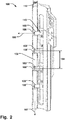
Fig. 3 schematically illustrates an inductor for welding of a packaging material, in a side-view, according to one example; -
Fig. 4 schematically illustrates an inductor for welding of a packaging material, in a side-view, according to one example; and -
Fig. 5 is a flowchart of a method of welding a packaging material. - Specific examples of the invention will now be described with reference to the accompanying drawings. This invention may, however, be embodied in many different forms and should not be construed as limited to the examples set forth herein; rather, these examples are provided so that this disclosure will be thorough and complete, and will fully convey the scope of the invention to those skilled in the art. The terminology used in the detailed description of the examples illustrated in the accompanying drawings is not intended to be limiting of the invention. In the drawings, like numbers refer to like elements.
-
Fig. 1 schematically illustrates aninductor 100 for induction welding of apackaging material 101 having at least one layer of metal foil. Theinductor 100 comprises awelding surface 102 configured to be arranged opposite thepackaging material 101 for heating thereof. At least onespacing element welding surface 102 in afirst direction 104 towards thepackaging material 101, when thepackaging material 101 is arranged opposite thewelding surface 102. The at least onespacing element packaging material 101 from thewelding surface 102 by an off-set distance 105. By having at least one spacing element 103 - 103''' protruding from thewelding surface 102 thepackaging material 101 is prevented from contacting thewelding surface 102, and is instead kept at the off-setdistance 105 from thewelding surface 105. Build-up of residues from thepackaging material 101 on thewelding surface 102, e.g. from polyethylene that is formed due to the high temperature exposed to thepackaging material 101, can thus be prevented. This advantageously provides increasing the service interval, since less cleaning of theinductor 100 is required. At the same time, the at least one spacing element 103 - 103''' protruding from thewelding surface 102 provides for achieving stable characteristics of the electrical parameters of the induction circuit since thepackaging material 101 can be readily arranged against the at least one spacing element 103 - 103''' and thereby be kept at the well-defined off-set distance 105 from thewelding surface 102. Having such defined separation minimizes the risk of fluctuations in e.g. the impedance of the induction heating circuit, which provides for optimized control of the welding process. The sealing procedure of the packaging containers may thus be made more reliable and completed in a shorter amount of time, since it is possible to more accurately control the power delivery to the inductor, thanks to the improved stability of the electrical characteristics involved the process. The lifetime of theinductor 100 can also be increased, due to the optimized power control and due to less wear on the inductor, which is a result of less exposure to contaminants and partly also because of fewer cleaning operations which contribute to the overall wear of theinductor 100. Thus, having at least one spacing element 103 - 103''' protruding from thewelding surface 102 provides for a more robust inductor with increased lifetime, as well as improved control of the induction sealing process. The protrusion from thewelding surface 102 by the least one spacing element 103 - 103''' should be construed as an extension from a plane in which thewelding surface 102 of the inductor lies. I.e. turning to e.g.Fig. 1 , thespacing element 103 extends or protrudes beyond such plane (which extends in the feed direction 107) in thefirst direction 104. In the example ofFig. 1 it is clear that thespacing element 103 may not need to be in abutment with thewelding surface 102, but should regardless be construed as protruding or extending form thewelding surface 102 in thefirst direction 104 towards thepackaging material 101 as discussed. - As schematically illustrated in e.g.
Fig. 1 , the at least one spacing element 103 - 103''' may comprise at least one roller 103 - 103''' being pivotally fixed to theinductor 100 and being rotatable around arotational axis 106, which is further illustrated in the top-down view of theinductor 100 inFig. 2 . The at least one roller 103 - 103''' is configured to convey thepackaging material 101 across thewelding surface 102 at the off-set distance 105. Having at least one roller 103 - 103''' provides for attaining the off-set distance 105 with the advantages as elucidated above while allowing for an efficient conveying of thepackaging material 101 across thewelding surface 102 with a minimum of frictional force exerted between thepackaging material 101 and thewelding surface 102. The at least one roller 103 - 103''' may thus freely rotate relative thewelding surface 102. It is also conceivable however that the at least one spacing element 103 - 103''' may comprise a static, i.e. not rotating, low friction material that provides for an efficient sliding movement between thepackaging material 101 and the at least one spacing element 103 - 103'''. A static spacing element 103 - 103''' may provide for aninductor 100 requiring a minimum of maintenance, albeit at least one roller 103 - 103''' may provide for advantages in terms of providing a minimum of frictional force against thepackaging material 101. A static spacing element 103 - 103''' may comprise a material having a low friction coefficient while being highly resistant to contaminations and abrasion. It is further conceivable that at least one static spacing element 103 - 103''' may be combined with at least one movable spacing element 103 - 103''' in certain applications of theinductor 100 to provide for a balance between maintenance, manufacturing costs and movability. It is further conceivable that other movable spacing elements 103 - 103''' may be provided, such as spherical elements which may rotate relative to thewelding surface 102. - The at least one roller 103 - 103''' may be extend across at least half of the
width 112 of thewelding surface 102, in the direction of therotational axis 106. This may provide for further ensuring that thepackaging material 101 is maintained at the off-setdistance 105 from thewelding surface 102 and that thepackaging material 101 can be effectively and reliably conveyed over thewelding surface 102. - As illustrated in e.g.
Figs. 1 and2 , thewelding surface 102 may have an elongated extension in afeed direction 107 in which thepackaging material 101 is conveyed, when arranged opposite thewelding surface 102. Therotational axis 106 may extend parallel with thewelding surface 102, i.e. in the plane of thewelding surface 102, and perpendicular to thefeed direction 107. Having therotational axis 106 extending in the plane of thewelding surface 102 may provide for further enduring that thepackaging material 101 is kept at a constant off-setdistance 105 across thewelding surface 102. By having therotational axis 106 extending perpendicular to thefeed direction 107 thepackaging material 101 may be exposed to a minimum of frictional force from the at least one roller 103 - 103'''. - The at least one roller 103 - 103''' may be arranged in a
corresponding recess welding surface 102, as illustrated in e.g. the side-views ofFigs. 1 and3 or the perspective view ofFig. 4 . Arranging the at least one roller 103 - 103''' in a recess allows for selecting an optimized diameter of the roller 103 - 103''' in order to provide for the desired dynamics of the relative movement between the roller 103 - 103''' and thepackaging material 101, while being able to set the off-setdistance 105 to the desired value. - The
inductor 100 may comprise at least onesupport 110 in which the at least one roller 103 - 103''' is pivotally fixed, as schematically illustrated inFig. 2 . The at least onesupport 110 may be movably fixated to theinductor 100 and thereby be movable relative to thewelding surface 102 such that the corresponding roller 103 - 103"', pivotally fixed to thesupport 110, has a variable position in thefirst direction 104, perpendicular to thewelding surface 102 and therotational axis 106. The off-setdistance 105 may thus be readily varied and set to a range of values by moving thesupport 110 and the corresponding roller 103 - 103''' in thefirst direction 104, towards thepackaging material 101. In case of having a plurality of rollers 103 - 103''', each of the rollers 103 - 103''' may be individually moved relative to each other to optimize the trajectory of thepackaging material 101 across thewelding surface 102. It is also conceivable that in case of having static spacing elements 103 - 103''', as discussed above, the position of the static spacing elements 103 - 103''' in thefirst direction 104 may be individually adjusted. - The at least one roller 103 - 103''' may comprise a cylindrical surface covered by a resilient material (not shown). Such resilient material may accommodate slight movements of the
packaging material 101 in thefirst direction 104 and thereby smoothen out possible vibrations occurring in thepackaging material 101 when conveyed over thewelding surface 102. This may provide for increased stability in the trajectory of thepackaging material 101 relative to theinductor 100 and further process stability with regards to the electrical characteristics of the inductive heating circuit established via the magnetic coupling of theinductor 100 to the metal foil of thepackaging material 101. - The
Inductor 100 may comprise a plurality ofspacing elements Figs. 1-4 . The number of spacing elements 103 - 103''' may be selected depending on the particular application which may dictate varying requirements with respect to e.g. the dimensions of theinductor 100.Figs. 1-4 illustrate examples with four spacing elements 103 - 103"', i.e. four rollers 103 - 103''' in these examples, which should however not be seen as limiting but instead mere examples of a number of spacing elements 103 - 103'''. Thus, it is conceivable that the number of spacing elements may be more or less than shown in the provided examples, depending on e.g. the length of theinductor 100 in thefeed direction 107. The plurality of spacing elements 103 - 103''' may be separated from each other by a setseparation distance 109 defined such that thepackaging material 101 remains separated from thewelding surface 102 along theseparation distance 109 when conveyed in thefeed direction 107. Thus theseparation distance 109 is chosen such that thepackaging material 101 does not abut thewelding surface 102 between the spacing elements 103 - 103''' given a particular application. E.g. the speed by which thepackaging material 101 is conveyed in thefeed direction 107 over thewelding surface 102 may be different in various applications, as well as the properties of the packaging material itself, which may affect the amount of flexing of thepackaging material 101 between two spacing elements 103 - 103"'. Theseparation distance 109 may thus be varied to accommodate such factors and prevent flexing of thepackaging material 101 to such extend it touches thewelding surface 102. It is also conceivable that the spacing elements 103 - 103''' may be movable in thefeed direction 107, i.e. being configured to be fixated atdifferent separation distances 109, to provide for substantially maintaining the off-setdistance 105 across thewelding surface 102 while havingseparation distances 109 that minimize friction on thepackaging material 101. - The plurality of spacing elements 103 - 103''' may comprise a plurality of
rollers corresponding recess welding surface 102, as schematically illustrated in the examples ofFigs. 1-4 . Such configuration may provide for a particularlyadvantageous inductor 100 with improved lifetime and stable electrical characteristics of the inductive heating circuit. - The at least one spacing element 103 - 103''' may be arranged such that the off-set
distance 105 is substantially constant over thewelding surface 102 along afeed direction 107 in which thepackaging material 101 is conveyed, when arranged opposite thewelding surface 102. A constant off-setdistance 105 may further provide for achieving optimal stability and control of the electrical parameters of the inductive heating circuit. - The at least one spacing element 103 - 103''' may be thermally insulated from the
welding surface 102. Thermally insulated should be construed as decreased thermal coupling between the at least one spacing element 103 - 103''' and thewelding surface 102 so that the amount of thermal power transferred therebetween is reduced. The at least one spacing element 103 - 103''' may be thermally insulated from thewelding surface 102 by having a thermally insulating material arranged inbetween the at least one spacing element 103 - 103''' and thewelding surface 102, i.e. a material having a lower heat transfer coefficient than thewelding surface 102. Alternatively, the at least one spacing element 103 - 103''' may be separated from thewelding surface 102 as in the case of having at least one roller 103 - 103''', shown in the examples ofFigs. 1-4 . The air gap between the at least one roller 103 - 103''' and thewelding surface 102 may be varied to achieve the desired amount of thermal insulation, so that thepackaging material 101 is not heated excessively when in contact with the at least one roller 103 - 103"'. Formation of compound residues such as polyethylene on the at least one roller 103 - 103''' may thereby be prevented. - The at least one spacing element 103 - 103''' may be removably fixated to the
inductor 100. It is thus possible to allow for efficient and facilitated maintenance and optimization of the at least one spacing element 103 - 103''' on theinductor 100. It is also conceivable that the number of spacing element 103 - 103''', e.g. rollers 103 - 103''', may be varied as desired, by removing or attaching rollers 103 - 103''' to theinductor 100 depending on the particular application. A high degree of customizability of theinductor 100 is thus provided and replacement of theinductor 100 as a whole can be avoided. - A sealing machine for sealing a
packaging material 101 is provided. The sealing machine comprises aninductor 100 as described above in relation toFigs. 1-4 . In the sealing machine, thepackaging material 101 is conveyed to be arranged opposite awelding surface 102 of theinductor 100, and at least onespacing element welding surface 102 in afirst direction 104 towards thepackaging material 101, whereupon the least one spacing element 103 - 103''' separates thepackaging material 101 from thewelding surface 102 by an off-setdistance 105 while being conveyed in sealing machine. This thus provides for a sealing machine with the advantages as described above in relation to theinductor 100 andFigs. 1-4 . -
Fig. 5 illustrates a flow chart of amethod 300 of welding apackaging material 101 having at least one layer of metal foil with aninductor 100. The order in which the steps of themethod 300 are described and illustrated should not be construed as limiting and it is conceivable that the steps can be performed in varying order. Theinductor 100 has awelding surface 102 configured to be arranged opposite thepackaging material 101 for heating thereof. Themethod 300 comprises conveying 301 thepackaging material 101 over thewelding surface 102 at an off-setdistance 105 from thewelding surface 102 by moving 302 thepackaging material 101 over at least onespacing element welding surface 102. Amethod 300 of welding apackaging material 101 with aninductor 100 is thus provided with the associated advantages as described above in relation to theinductor 100 andFigs. 1-4 . - The at least one spacing element 103 - 103''' may comprise a plurality of
rollers method 300 may comprise rolling 303 thepackaging material 101 on the rollers 103 - 103''' over thewelding surface 102 to maintain the off-setdistance 105 between thepackaging material 101 and thewelding surface 102 along afeed direction 107 in which thewelding surface 102 extends and in which direction thepackaging material 101 is conveyed. - The present invention has been described above with reference to specific examples. However, other examples than the above described are equally possible within the scope of the invention. The different features and steps of the invention may be combined in other combinations than those described. The scope of the invention is only limited by the appended patent claims.
- More generally, those skilled in the art will readily appreciate that all parameters, dimensions, materials, and configurations described herein are meant to be exemplary and that the actual parameters, dimensions, materials, and/or configurations will depend upon the specific application or applications for which the teachings of the present invention is/are used.
Claims (14)
- An inductor (100) for induction welding of a packaging material (101) having at least one layer of metal foil, the inductor comprising
a welding surface (102) configured to be arranged opposite the packaging material for heating thereof, and
at least one spacing element (103, 103', 103", 103''') arranged to protrude from the welding surface in a first direction (104) towards the packaging material, when the packaging material is arranged opposite the welding surface, whereupon the least one spacing element separates the packaging material from the welding surface by an off-set distance (105). - Inductor according to claim 1, wherein the at least one spacing element comprises at least one roller (103, 103', 103", 103''') being pivotally fixed to the inductor and being rotatable around a rotational axis (106), whereby the at least one roller is configured to convey the packaging material across the welding surface at the off-set distance.
- Inductor according to claim 2, wherein the welding surface has an elongated extension in a feed direction (107) in which the packaging material is conveyed, when arranged opposite the welding surface, and where the rotational axis extends parallel with the welding surface and perpendicular to the feed direction.
- Inductor according to claim 2 or 3, wherein the at least one roller is arranged in a corresponding recess (108, 108', 108", 108''') in the welding surface.
- Inductor according to any of claims 2 - 4, comprising at least one support (110) in which the at least one roller is pivotally fixed, wherein the at least one support is movable relative to the welding surface such that the roller pivotally fixed thereto has a variable position in the first direction, perpendicular to the welding surface and the rotational axis.
- Inductor according to any of claims 2 - 5, wherein the at least one roller comprises a cylindrical surface covered by a resilient material (111).
- Inductor according to any of claims 1 - 6, comprising a plurality of spacing elements (103, 103', 103", 103''') separated from each other by a set separation distance (109) defined such that the packaging material remains separated from the welding surface along the separation distance when conveyed in the feed direction.
- Inductor according to claim 7, wherein the plurality of spacing elements comprises a plurality of rollers (103, 103', 103", 103''') each arranged in a corresponding recess (108, 108', 108", 108''') in the welding surface.
- Inductor according to any of claims 1 - 8, wherein the at least one spacing element is arranged such that the off-set distance is substantially constant over the welding surface along a feed direction (107) in which the packaging material is conveyed, when arranged opposite the welding surface.
- Inductor according to any of claims 1 - 9, wherein the at least one spacing element is thermally insulated from the welding surface.
- Inductor according to any of claims 1 - 10, wherein the at least one spacing element is removably fixated to the inductor.
- A sealing machine for sealing a packaging material (101), comprising an inductor (100) according to any of claims 1 - 11, wherein the packaging material is conveyed to be arranged opposite a welding surface (102) of the inductor and at least one spacing element (103, 103', 103", 103''') is arranged to protrude from the welding surface in a first direction (104) towards the packaging material, whereupon the least one spacing element separates the packaging material from the welding surface by an off-set distance (105) while being conveyed in sealing machine.
- A method (300) of welding a packaging material (101) having at least one layer of metal foil with an inductor (100), the inductor having a welding surface (102) configured to be arranged opposite the packaging material for heating thereof, the method comprising
conveying (301) the packaging material over the welding surface at an off-set distance (105) from the welding surface by moving (302) the packaging material over at least one spacing element (103, 103', 103", 103''') arranged to protrude from the welding surface. - Method according to claim 13, wherein the at least one spacing element comprises a plurality of rollers (103, 103', 103", 103'''), the method comprising
rolling (303) the packaging material on the rollers over the welding surface to maintain the off-set distance between the packaging material and the welding surface along a feed direction (107) in which the welding surface extends and in which direction the packaging material is conveyed.
Applications Claiming Priority (1)
| Application Number | Priority Date | Filing Date | Title |
|---|---|---|---|
| EP17159041 | 2017-03-03 |
Publications (2)
| Publication Number | Publication Date |
|---|---|
| EP3369557A1 true EP3369557A1 (en) | 2018-09-05 |
| EP3369557B1 EP3369557B1 (en) | 2025-05-07 |
Family
ID=58265779
Family Applications (1)
| Application Number | Title | Priority Date | Filing Date |
|---|---|---|---|
| EP18159498.7A Active EP3369557B1 (en) | 2017-03-03 | 2018-03-01 | Inductor for induction welding of a packaging material |
Country Status (6)
| Country | Link |
|---|---|
| US (1) | US11247405B2 (en) |
| EP (1) | EP3369557B1 (en) |
| JP (1) | JP7723469B2 (en) |
| CN (2) | CN108528851B (en) |
| MX (1) | MX2019010209A (en) |
| WO (1) | WO2018158383A1 (en) |
Families Citing this family (1)
| Publication number | Priority date | Publication date | Assignee | Title |
|---|---|---|---|---|
| CN108528851B (en) * | 2017-03-03 | 2022-02-01 | 利乐拉瓦尔集团及财务有限公司 | Inductor for induction welding of packaging material |
Citations (2)
| Publication number | Priority date | Publication date | Assignee | Title |
|---|---|---|---|---|
| US5767491A (en) * | 1995-01-10 | 1998-06-16 | Tetra Laval Holding & Finance S.A. | Heating apparatus for making a continuous longitudinal seam weld on a laminated packaging material web |
| WO2015078907A1 (en) * | 2013-11-29 | 2015-06-04 | Tetra Laval Holdings & Finance S.A. | An induction heating device |
Family Cites Families (13)
| Publication number | Priority date | Publication date | Assignee | Title |
|---|---|---|---|---|
| DE1454995A1 (en) | 1965-07-12 | 1969-09-18 | Bahlsen Werner | Method and device for joining surfaces of thermoplastic plastics |
| US3676271A (en) * | 1967-10-23 | 1972-07-11 | American Can Co | Apparatus for applying a strip member to a cylindrical container body |
| DE2653753C2 (en) * | 1976-11-26 | 1986-04-17 | Robert Bosch Gmbh, 7000 Stuttgart | Device for producing a packaging tube from a packaging material web by welding the edge areas |
| JPS5636732Y2 (en) * | 1979-05-24 | 1981-08-29 | ||
| SE464019B (en) * | 1989-03-13 | 1991-02-25 | Tetra Pak Holdings & Finance | DEVICE FOR CONTINUOUS INDUCTION WELDING OF PACKAGING MATERIAL |
| GB8928799D0 (en) * | 1989-12-20 | 1990-02-28 | Du Pont Canada | Self voiding jaw for packaging machine |
| JPH0419125A (en) * | 1990-05-15 | 1992-01-23 | Somar Corp | Laminator |
| FR2748415B1 (en) * | 1996-05-09 | 1998-06-26 | Etex De Rech Tech Soc | CONNECTING ELEMENT FOR AN ASSEMBLY OF THERMOPLASTIC MATERIALS BY WELDING AND METHOD FOR MANUFACTURING SUCH AN ELEMENT |
| EP2008795B1 (en) * | 2007-06-28 | 2011-08-31 | Tetra Laval Holdings & Finance SA | Induction sealing device for heat sealing packaging material for producing sealed packages of pourable food products |
| AT507384B1 (en) * | 2008-09-18 | 2011-07-15 | Westwind Verpackungen Gmbh | CLOSING DEVICE FOR CLOSING PREFERABLY BAGGED PACKAGING UNITS |
| WO2014072477A1 (en) * | 2012-11-09 | 2014-05-15 | Tetra Laval Holdings & Finance S.A. | Pressure pad and heat-sealing device having such a pressure pad |
| DE102014119700B3 (en) | 2014-12-30 | 2015-11-19 | Sig Technology Ag | Apparatus and method for inductive heating of packing coats |
| CN108528851B (en) * | 2017-03-03 | 2022-02-01 | 利乐拉瓦尔集团及财务有限公司 | Inductor for induction welding of packaging material |
-
2018
- 2018-02-13 CN CN201810148711.1A patent/CN108528851B/en active Active
- 2018-02-13 CN CN201820255615.2U patent/CN208134777U/en not_active Withdrawn - After Issue
- 2018-03-01 WO PCT/EP2018/055074 patent/WO2018158383A1/en not_active Ceased
- 2018-03-01 US US16/489,933 patent/US11247405B2/en active Active
- 2018-03-01 JP JP2019547674A patent/JP7723469B2/en active Active
- 2018-03-01 MX MX2019010209A patent/MX2019010209A/en unknown
- 2018-03-01 EP EP18159498.7A patent/EP3369557B1/en active Active
Patent Citations (2)
| Publication number | Priority date | Publication date | Assignee | Title |
|---|---|---|---|---|
| US5767491A (en) * | 1995-01-10 | 1998-06-16 | Tetra Laval Holding & Finance S.A. | Heating apparatus for making a continuous longitudinal seam weld on a laminated packaging material web |
| WO2015078907A1 (en) * | 2013-11-29 | 2015-06-04 | Tetra Laval Holdings & Finance S.A. | An induction heating device |
Also Published As
| Publication number | Publication date |
|---|---|
| JP2020510584A (en) | 2020-04-09 |
| EP3369557B1 (en) | 2025-05-07 |
| US20190389145A1 (en) | 2019-12-26 |
| CN108528851B (en) | 2022-02-01 |
| CN108528851A (en) | 2018-09-14 |
| CN208134777U (en) | 2018-11-23 |
| JP7723469B2 (en) | 2025-08-14 |
| WO2018158383A1 (en) | 2018-09-07 |
| MX2019010209A (en) | 2019-10-09 |
| US11247405B2 (en) | 2022-02-15 |
Similar Documents
| Publication | Publication Date | Title |
|---|---|---|
| US11110540B2 (en) | Extruder for metal material and 3D printer using the same | |
| US10562236B2 (en) | Device and method for inductively heating package sleeves | |
| CA2685143C (en) | Method and device for electromagnetic welding of moulded parts | |
| JP6336026B2 (en) | Heater and image heating apparatus equipped with the heater | |
| US10737443B2 (en) | Device and method for inductive sealing of a plurality of plies of a laminate | |
| EP3431267B1 (en) | Induction sealing device | |
| JP2023505823A5 (en) | ||
| US20040065660A1 (en) | Fixing device using induction heating | |
| SE464019B (en) | DEVICE FOR CONTINUOUS INDUCTION WELDING OF PACKAGING MATERIAL | |
| US8050612B2 (en) | Fixing device having a temperature-uniforming roller | |
| EP3369557B1 (en) | Inductor for induction welding of a packaging material | |
| JP2014059508A (en) | Heater and image heating device including the same | |
| US9857743B2 (en) | Fixing device and image forming apparatus having the same | |
| EP4523048A1 (en) | Heating device, fixing device, and image forming apparatus | |
| CN102083717A (en) | Transport roller | |
| US12158713B2 (en) | Heater and image heating device | |
| JP2016219371A (en) | Induction heating device | |
| KR101831787B1 (en) | fusing device and fusing method | |
| EP3711454B1 (en) | Resilient air-cooled induction heating cables | |
| US8559156B2 (en) | Method and apparatus for charging or neutralizing an object using a charged piece of conductive plastic | |
| US20170031286A1 (en) | Image heating apparatus and heater used in same | |
| JP2017009169A (en) | Coating material drying method and coating material drying device | |
| JP2010096972A (en) | Fixing belt and fixing device | |
| CN103895065A (en) | Heat preserving board grooving device |
Legal Events
| Date | Code | Title | Description |
|---|---|---|---|
| PUAI | Public reference made under article 153(3) epc to a published international application that has entered the european phase |
Free format text: ORIGINAL CODE: 0009012 |
|
| STAA | Information on the status of an ep patent application or granted ep patent |
Free format text: STATUS: THE APPLICATION HAS BEEN PUBLISHED |
|
| AK | Designated contracting states |
Kind code of ref document: A1 Designated state(s): AL AT BE BG CH CY CZ DE DK EE ES FI FR GB GR HR HU IE IS IT LI LT LU LV MC MK MT NL NO PL PT RO RS SE SI SK SM TR |
|
| AX | Request for extension of the european patent |
Extension state: BA ME |
|
| STAA | Information on the status of an ep patent application or granted ep patent |
Free format text: STATUS: REQUEST FOR EXAMINATION WAS MADE |
|
| 17P | Request for examination filed |
Effective date: 20190305 |
|
| RBV | Designated contracting states (corrected) |
Designated state(s): AL AT BE BG CH CY CZ DE DK EE ES FI FR GB GR HR HU IE IS IT LI LT LU LV MC MK MT NL NO PL PT RO RS SE SI SK SM TR |
|
| STAA | Information on the status of an ep patent application or granted ep patent |
Free format text: STATUS: EXAMINATION IS IN PROGRESS |
|
| 17Q | First examination report despatched |
Effective date: 20210507 |
|
| GRAP | Despatch of communication of intention to grant a patent |
Free format text: ORIGINAL CODE: EPIDOSNIGR1 |
|
| STAA | Information on the status of an ep patent application or granted ep patent |
Free format text: STATUS: GRANT OF PATENT IS INTENDED |
|
| RIC1 | Information provided on ipc code assigned before grant |
Ipc: B29K 711/12 20060101ALN20241216BHEP Ipc: B29K 705/02 20060101ALN20241216BHEP Ipc: B29K 23/00 20060101ALN20241216BHEP Ipc: B29L 9/00 20060101ALN20241216BHEP Ipc: B65B 9/20 20120101ALI20241216BHEP Ipc: B65B 51/26 20060101ALI20241216BHEP Ipc: B65B 51/22 20060101ALI20241216BHEP Ipc: B29C 65/36 20060101AFI20241216BHEP |
|
| INTG | Intention to grant announced |
Effective date: 20250103 |
|
| GRAS | Grant fee paid |
Free format text: ORIGINAL CODE: EPIDOSNIGR3 |
|
| GRAA | (expected) grant |
Free format text: ORIGINAL CODE: 0009210 |
|
| STAA | Information on the status of an ep patent application or granted ep patent |
Free format text: STATUS: THE PATENT HAS BEEN GRANTED |
|
| AK | Designated contracting states |
Kind code of ref document: B1 Designated state(s): AL AT BE BG CH CY CZ DE DK EE ES FI FR GB GR HR HU IE IS IT LI LT LU LV MC MK MT NL NO PL PT RO RS SE SI SK SM TR |
|
| REG | Reference to a national code |
Ref country code: GB Ref legal event code: FG4D |
|
| REG | Reference to a national code |
Ref country code: CH Ref legal event code: EP |
|
| REG | Reference to a national code |
Ref country code: DE Ref legal event code: R096 Ref document number: 602018081663 Country of ref document: DE |
|
| REG | Reference to a national code |
Ref country code: IE Ref legal event code: FG4D |
|
| REG | Reference to a national code |
Ref country code: NL Ref legal event code: MP Effective date: 20250507 |
|
| PG25 | Lapsed in a contracting state [announced via postgrant information from national office to epo] |
Ref country code: FI Free format text: LAPSE BECAUSE OF FAILURE TO SUBMIT A TRANSLATION OF THE DESCRIPTION OR TO PAY THE FEE WITHIN THE PRESCRIBED TIME-LIMIT Effective date: 20250507 Ref country code: PT Free format text: LAPSE BECAUSE OF FAILURE TO SUBMIT A TRANSLATION OF THE DESCRIPTION OR TO PAY THE FEE WITHIN THE PRESCRIBED TIME-LIMIT Effective date: 20250908 Ref country code: ES Free format text: LAPSE BECAUSE OF FAILURE TO SUBMIT A TRANSLATION OF THE DESCRIPTION OR TO PAY THE FEE WITHIN THE PRESCRIBED TIME-LIMIT Effective date: 20250507 |
|
| REG | Reference to a national code |
Ref country code: LT Ref legal event code: MG9D |
|
| PG25 | Lapsed in a contracting state [announced via postgrant information from national office to epo] |
Ref country code: NO Free format text: LAPSE BECAUSE OF FAILURE TO SUBMIT A TRANSLATION OF THE DESCRIPTION OR TO PAY THE FEE WITHIN THE PRESCRIBED TIME-LIMIT Effective date: 20250807 Ref country code: GR Free format text: LAPSE BECAUSE OF FAILURE TO SUBMIT A TRANSLATION OF THE DESCRIPTION OR TO PAY THE FEE WITHIN THE PRESCRIBED TIME-LIMIT Effective date: 20250808 |
|
| PG25 | Lapsed in a contracting state [announced via postgrant information from national office to epo] |
Ref country code: PL Free format text: LAPSE BECAUSE OF FAILURE TO SUBMIT A TRANSLATION OF THE DESCRIPTION OR TO PAY THE FEE WITHIN THE PRESCRIBED TIME-LIMIT Effective date: 20250507 Ref country code: NL Free format text: LAPSE BECAUSE OF FAILURE TO SUBMIT A TRANSLATION OF THE DESCRIPTION OR TO PAY THE FEE WITHIN THE PRESCRIBED TIME-LIMIT Effective date: 20250507 |
|
| REG | Reference to a national code |
Ref country code: AT Ref legal event code: MK05 Ref document number: 1792022 Country of ref document: AT Kind code of ref document: T Effective date: 20250507 |
|
| PG25 | Lapsed in a contracting state [announced via postgrant information from national office to epo] |
Ref country code: BG Free format text: LAPSE BECAUSE OF FAILURE TO SUBMIT A TRANSLATION OF THE DESCRIPTION OR TO PAY THE FEE WITHIN THE PRESCRIBED TIME-LIMIT Effective date: 20250507 |
|
| PG25 | Lapsed in a contracting state [announced via postgrant information from national office to epo] |
Ref country code: HR Free format text: LAPSE BECAUSE OF FAILURE TO SUBMIT A TRANSLATION OF THE DESCRIPTION OR TO PAY THE FEE WITHIN THE PRESCRIBED TIME-LIMIT Effective date: 20250507 |
|
| PG25 | Lapsed in a contracting state [announced via postgrant information from national office to epo] |
Ref country code: AT Free format text: LAPSE BECAUSE OF FAILURE TO SUBMIT A TRANSLATION OF THE DESCRIPTION OR TO PAY THE FEE WITHIN THE PRESCRIBED TIME-LIMIT Effective date: 20250507 |
|
| PG25 | Lapsed in a contracting state [announced via postgrant information from national office to epo] |
Ref country code: RS Free format text: LAPSE BECAUSE OF FAILURE TO SUBMIT A TRANSLATION OF THE DESCRIPTION OR TO PAY THE FEE WITHIN THE PRESCRIBED TIME-LIMIT Effective date: 20250807 |
|
| PG25 | Lapsed in a contracting state [announced via postgrant information from national office to epo] |
Ref country code: IS Free format text: LAPSE BECAUSE OF FAILURE TO SUBMIT A TRANSLATION OF THE DESCRIPTION OR TO PAY THE FEE WITHIN THE PRESCRIBED TIME-LIMIT Effective date: 20250907 |
|
| PG25 | Lapsed in a contracting state [announced via postgrant information from national office to epo] |
Ref country code: LV Free format text: LAPSE BECAUSE OF FAILURE TO SUBMIT A TRANSLATION OF THE DESCRIPTION OR TO PAY THE FEE WITHIN THE PRESCRIBED TIME-LIMIT Effective date: 20250507 |
|
| PG25 | Lapsed in a contracting state [announced via postgrant information from national office to epo] |
Ref country code: DK Free format text: LAPSE BECAUSE OF FAILURE TO SUBMIT A TRANSLATION OF THE DESCRIPTION OR TO PAY THE FEE WITHIN THE PRESCRIBED TIME-LIMIT Effective date: 20250507 Ref country code: SM Free format text: LAPSE BECAUSE OF FAILURE TO SUBMIT A TRANSLATION OF THE DESCRIPTION OR TO PAY THE FEE WITHIN THE PRESCRIBED TIME-LIMIT Effective date: 20250507 |
|
| PG25 | Lapsed in a contracting state [announced via postgrant information from national office to epo] |
Ref country code: CZ Free format text: LAPSE BECAUSE OF FAILURE TO SUBMIT A TRANSLATION OF THE DESCRIPTION OR TO PAY THE FEE WITHIN THE PRESCRIBED TIME-LIMIT Effective date: 20250507 |
|
| PG25 | Lapsed in a contracting state [announced via postgrant information from national office to epo] |
Ref country code: EE Free format text: LAPSE BECAUSE OF FAILURE TO SUBMIT A TRANSLATION OF THE DESCRIPTION OR TO PAY THE FEE WITHIN THE PRESCRIBED TIME-LIMIT Effective date: 20250507 |
|
| PG25 | Lapsed in a contracting state [announced via postgrant information from national office to epo] |
Ref country code: SK Free format text: LAPSE BECAUSE OF FAILURE TO SUBMIT A TRANSLATION OF THE DESCRIPTION OR TO PAY THE FEE WITHIN THE PRESCRIBED TIME-LIMIT Effective date: 20250507 Ref country code: RO Free format text: LAPSE BECAUSE OF FAILURE TO SUBMIT A TRANSLATION OF THE DESCRIPTION OR TO PAY THE FEE WITHIN THE PRESCRIBED TIME-LIMIT Effective date: 20250507 |
|
| REG | Reference to a national code |
Ref country code: DE Ref legal event code: R097 Ref document number: 602018081663 Country of ref document: DE |
|
| PLBE | No opposition filed within time limit |
Free format text: ORIGINAL CODE: 0009261 |
|
| STAA | Information on the status of an ep patent application or granted ep patent |
Free format text: STATUS: NO OPPOSITION FILED WITHIN TIME LIMIT |
|
| REG | Reference to a national code |
Ref country code: CH Ref legal event code: L10 Free format text: ST27 STATUS EVENT CODE: U-0-0-L10-L00 (AS PROVIDED BY THE NATIONAL OFFICE) Effective date: 20260318 |
|
| PGFP | Annual fee paid to national office [announced via postgrant information from national office to epo] |
Ref country code: DE Payment date: 20260320 Year of fee payment: 9 |
|
| 26N | No opposition filed |
Effective date: 20260210 |
|
| PGFP | Annual fee paid to national office [announced via postgrant information from national office to epo] |
Ref country code: IT Payment date: 20260320 Year of fee payment: 9 |