EP3369487A1 - Shroud and method for implementing abradable coating - Google Patents
Shroud and method for implementing abradable coating Download PDFInfo
- Publication number
- EP3369487A1 EP3369487A1 EP17747140.6A EP17747140A EP3369487A1 EP 3369487 A1 EP3369487 A1 EP 3369487A1 EP 17747140 A EP17747140 A EP 17747140A EP 3369487 A1 EP3369487 A1 EP 3369487A1
- Authority
- EP
- European Patent Office
- Prior art keywords
- slurry
- abradable coating
- pattern
- coating layer
- implementing
- Prior art date
- Legal status (The legal status is an assumption and is not a legal conclusion. Google has not performed a legal analysis and makes no representation as to the accuracy of the status listed.)
- Granted
Links
Images
Classifications
-
- F—MECHANICAL ENGINEERING; LIGHTING; HEATING; WEAPONS; BLASTING
- F01—MACHINES OR ENGINES IN GENERAL; ENGINE PLANTS IN GENERAL; STEAM ENGINES
- F01D—NON-POSITIVE DISPLACEMENT MACHINES OR ENGINES, e.g. STEAM TURBINES
- F01D11/00—Preventing or minimising internal leakage of working-fluid, e.g. between stages
- F01D11/08—Preventing or minimising internal leakage of working-fluid, e.g. between stages for sealing space between rotor blade tips and stator
- F01D11/12—Preventing or minimising internal leakage of working-fluid, e.g. between stages for sealing space between rotor blade tips and stator using a rubstrip, e.g. erodible. deformable or resiliently-biased part
- F01D11/122—Preventing or minimising internal leakage of working-fluid, e.g. between stages for sealing space between rotor blade tips and stator using a rubstrip, e.g. erodible. deformable or resiliently-biased part with erodable or abradable material
-
- B—PERFORMING OPERATIONS; TRANSPORTING
- B05—SPRAYING OR ATOMISING IN GENERAL; APPLYING FLUENT MATERIALS TO SURFACES, IN GENERAL
- B05D—PROCESSES FOR APPLYING FLUENT MATERIALS TO SURFACES, IN GENERAL
- B05D1/00—Processes for applying liquids or other fluent materials
- B05D1/26—Processes for applying liquids or other fluent materials performed by applying the liquid or other fluent material from an outlet device in contact with, or almost in contact with, the surface
-
- B—PERFORMING OPERATIONS; TRANSPORTING
- B05—SPRAYING OR ATOMISING IN GENERAL; APPLYING FLUENT MATERIALS TO SURFACES, IN GENERAL
- B05D—PROCESSES FOR APPLYING FLUENT MATERIALS TO SURFACES, IN GENERAL
- B05D3/00—Pretreatment of surfaces to which liquids or other fluent materials are to be applied; After-treatment of applied coatings, e.g. intermediate treating of an applied coating preparatory to subsequent applications of liquids or other fluent materials
- B05D3/02—Pretreatment of surfaces to which liquids or other fluent materials are to be applied; After-treatment of applied coatings, e.g. intermediate treating of an applied coating preparatory to subsequent applications of liquids or other fluent materials by baking
-
- B—PERFORMING OPERATIONS; TRANSPORTING
- B05—SPRAYING OR ATOMISING IN GENERAL; APPLYING FLUENT MATERIALS TO SURFACES, IN GENERAL
- B05D—PROCESSES FOR APPLYING FLUENT MATERIALS TO SURFACES, IN GENERAL
- B05D3/00—Pretreatment of surfaces to which liquids or other fluent materials are to be applied; After-treatment of applied coatings, e.g. intermediate treating of an applied coating preparatory to subsequent applications of liquids or other fluent materials
- B05D3/02—Pretreatment of surfaces to which liquids or other fluent materials are to be applied; After-treatment of applied coatings, e.g. intermediate treating of an applied coating preparatory to subsequent applications of liquids or other fluent materials by baking
- B05D3/0254—After-treatment
-
- B—PERFORMING OPERATIONS; TRANSPORTING
- B05—SPRAYING OR ATOMISING IN GENERAL; APPLYING FLUENT MATERIALS TO SURFACES, IN GENERAL
- B05D—PROCESSES FOR APPLYING FLUENT MATERIALS TO SURFACES, IN GENERAL
- B05D7/00—Processes, other than flocking, specially adapted for applying liquids or other fluent materials to particular surfaces or for applying particular liquids or other fluent materials
- B05D7/14—Processes, other than flocking, specially adapted for applying liquids or other fluent materials to particular surfaces or for applying particular liquids or other fluent materials to metal, e.g. car bodies
-
- B—PERFORMING OPERATIONS; TRANSPORTING
- B05—SPRAYING OR ATOMISING IN GENERAL; APPLYING FLUENT MATERIALS TO SURFACES, IN GENERAL
- B05D—PROCESSES FOR APPLYING FLUENT MATERIALS TO SURFACES, IN GENERAL
- B05D7/00—Processes, other than flocking, specially adapted for applying liquids or other fluent materials to particular surfaces or for applying particular liquids or other fluent materials
- B05D7/24—Processes, other than flocking, specially adapted for applying liquids or other fluent materials to particular surfaces or for applying particular liquids or other fluent materials for applying particular liquids or other fluent materials
-
- C—CHEMISTRY; METALLURGY
- C23—COATING METALLIC MATERIAL; COATING MATERIAL WITH METALLIC MATERIAL; CHEMICAL SURFACE TREATMENT; DIFFUSION TREATMENT OF METALLIC MATERIAL; COATING BY VACUUM EVAPORATION, BY SPUTTERING, BY ION IMPLANTATION OR BY CHEMICAL VAPOUR DEPOSITION, IN GENERAL; INHIBITING CORROSION OF METALLIC MATERIAL OR INCRUSTATION IN GENERAL
- C23C—COATING METALLIC MATERIAL; COATING MATERIAL WITH METALLIC MATERIAL; SURFACE TREATMENT OF METALLIC MATERIAL BY DIFFUSION INTO THE SURFACE, BY CHEMICAL CONVERSION OR SUBSTITUTION; COATING BY VACUUM EVAPORATION, BY SPUTTERING, BY ION IMPLANTATION OR BY CHEMICAL VAPOUR DEPOSITION, IN GENERAL
- C23C24/00—Coating starting from inorganic powder
- C23C24/08—Coating starting from inorganic powder by application of heat or pressure and heat
-
- C—CHEMISTRY; METALLURGY
- C23—COATING METALLIC MATERIAL; COATING MATERIAL WITH METALLIC MATERIAL; CHEMICAL SURFACE TREATMENT; DIFFUSION TREATMENT OF METALLIC MATERIAL; COATING BY VACUUM EVAPORATION, BY SPUTTERING, BY ION IMPLANTATION OR BY CHEMICAL VAPOUR DEPOSITION, IN GENERAL; INHIBITING CORROSION OF METALLIC MATERIAL OR INCRUSTATION IN GENERAL
- C23C—COATING METALLIC MATERIAL; COATING MATERIAL WITH METALLIC MATERIAL; SURFACE TREATMENT OF METALLIC MATERIAL BY DIFFUSION INTO THE SURFACE, BY CHEMICAL CONVERSION OR SUBSTITUTION; COATING BY VACUUM EVAPORATION, BY SPUTTERING, BY ION IMPLANTATION OR BY CHEMICAL VAPOUR DEPOSITION, IN GENERAL
- C23C24/00—Coating starting from inorganic powder
- C23C24/08—Coating starting from inorganic powder by application of heat or pressure and heat
- C23C24/082—Coating starting from inorganic powder by application of heat or pressure and heat without intermediate formation of a liquid in the layer
-
- C—CHEMISTRY; METALLURGY
- C23—COATING METALLIC MATERIAL; COATING MATERIAL WITH METALLIC MATERIAL; CHEMICAL SURFACE TREATMENT; DIFFUSION TREATMENT OF METALLIC MATERIAL; COATING BY VACUUM EVAPORATION, BY SPUTTERING, BY ION IMPLANTATION OR BY CHEMICAL VAPOUR DEPOSITION, IN GENERAL; INHIBITING CORROSION OF METALLIC MATERIAL OR INCRUSTATION IN GENERAL
- C23C—COATING METALLIC MATERIAL; COATING MATERIAL WITH METALLIC MATERIAL; SURFACE TREATMENT OF METALLIC MATERIAL BY DIFFUSION INTO THE SURFACE, BY CHEMICAL CONVERSION OR SUBSTITUTION; COATING BY VACUUM EVAPORATION, BY SPUTTERING, BY ION IMPLANTATION OR BY CHEMICAL VAPOUR DEPOSITION, IN GENERAL
- C23C26/00—Coating not provided for in groups C23C2/00 - C23C24/00
-
- C—CHEMISTRY; METALLURGY
- C23—COATING METALLIC MATERIAL; COATING MATERIAL WITH METALLIC MATERIAL; CHEMICAL SURFACE TREATMENT; DIFFUSION TREATMENT OF METALLIC MATERIAL; COATING BY VACUUM EVAPORATION, BY SPUTTERING, BY ION IMPLANTATION OR BY CHEMICAL VAPOUR DEPOSITION, IN GENERAL; INHIBITING CORROSION OF METALLIC MATERIAL OR INCRUSTATION IN GENERAL
- C23C—COATING METALLIC MATERIAL; COATING MATERIAL WITH METALLIC MATERIAL; SURFACE TREATMENT OF METALLIC MATERIAL BY DIFFUSION INTO THE SURFACE, BY CHEMICAL CONVERSION OR SUBSTITUTION; COATING BY VACUUM EVAPORATION, BY SPUTTERING, BY ION IMPLANTATION OR BY CHEMICAL VAPOUR DEPOSITION, IN GENERAL
- C23C28/00—Coating for obtaining at least two superposed coatings either by methods not provided for in a single one of groups C23C2/00 - C23C26/00 or by combinations of methods provided for in subclasses C23C and C25C or C25D
- C23C28/04—Coating for obtaining at least two superposed coatings either by methods not provided for in a single one of groups C23C2/00 - C23C26/00 or by combinations of methods provided for in subclasses C23C and C25C or C25D only coatings of inorganic non-metallic material
- C23C28/042—Coating for obtaining at least two superposed coatings either by methods not provided for in a single one of groups C23C2/00 - C23C26/00 or by combinations of methods provided for in subclasses C23C and C25C or C25D only coatings of inorganic non-metallic material including a refractory ceramic layer, e.g. refractory metal oxides, ZrO2, rare earth oxides
-
- C—CHEMISTRY; METALLURGY
- C23—COATING METALLIC MATERIAL; COATING MATERIAL WITH METALLIC MATERIAL; CHEMICAL SURFACE TREATMENT; DIFFUSION TREATMENT OF METALLIC MATERIAL; COATING BY VACUUM EVAPORATION, BY SPUTTERING, BY ION IMPLANTATION OR BY CHEMICAL VAPOUR DEPOSITION, IN GENERAL; INHIBITING CORROSION OF METALLIC MATERIAL OR INCRUSTATION IN GENERAL
- C23C—COATING METALLIC MATERIAL; COATING MATERIAL WITH METALLIC MATERIAL; SURFACE TREATMENT OF METALLIC MATERIAL BY DIFFUSION INTO THE SURFACE, BY CHEMICAL CONVERSION OR SUBSTITUTION; COATING BY VACUUM EVAPORATION, BY SPUTTERING, BY ION IMPLANTATION OR BY CHEMICAL VAPOUR DEPOSITION, IN GENERAL
- C23C28/00—Coating for obtaining at least two superposed coatings either by methods not provided for in a single one of groups C23C2/00 - C23C26/00 or by combinations of methods provided for in subclasses C23C and C25C or C25D
- C23C28/04—Coating for obtaining at least two superposed coatings either by methods not provided for in a single one of groups C23C2/00 - C23C26/00 or by combinations of methods provided for in subclasses C23C and C25C or C25D only coatings of inorganic non-metallic material
- C23C28/044—Coating for obtaining at least two superposed coatings either by methods not provided for in a single one of groups C23C2/00 - C23C26/00 or by combinations of methods provided for in subclasses C23C and C25C or C25D only coatings of inorganic non-metallic material coatings specially adapted for cutting tools or wear applications
-
- C—CHEMISTRY; METALLURGY
- C23—COATING METALLIC MATERIAL; COATING MATERIAL WITH METALLIC MATERIAL; CHEMICAL SURFACE TREATMENT; DIFFUSION TREATMENT OF METALLIC MATERIAL; COATING BY VACUUM EVAPORATION, BY SPUTTERING, BY ION IMPLANTATION OR BY CHEMICAL VAPOUR DEPOSITION, IN GENERAL; INHIBITING CORROSION OF METALLIC MATERIAL OR INCRUSTATION IN GENERAL
- C23C—COATING METALLIC MATERIAL; COATING MATERIAL WITH METALLIC MATERIAL; SURFACE TREATMENT OF METALLIC MATERIAL BY DIFFUSION INTO THE SURFACE, BY CHEMICAL CONVERSION OR SUBSTITUTION; COATING BY VACUUM EVAPORATION, BY SPUTTERING, BY ION IMPLANTATION OR BY CHEMICAL VAPOUR DEPOSITION, IN GENERAL
- C23C4/00—Coating by spraying the coating material in the molten state, e.g. by flame, plasma or electric discharge
- C23C4/01—Selective coating, e.g. pattern coating, without pre-treatment of the material to be coated
-
- C—CHEMISTRY; METALLURGY
- C23—COATING METALLIC MATERIAL; COATING MATERIAL WITH METALLIC MATERIAL; CHEMICAL SURFACE TREATMENT; DIFFUSION TREATMENT OF METALLIC MATERIAL; COATING BY VACUUM EVAPORATION, BY SPUTTERING, BY ION IMPLANTATION OR BY CHEMICAL VAPOUR DEPOSITION, IN GENERAL; INHIBITING CORROSION OF METALLIC MATERIAL OR INCRUSTATION IN GENERAL
- C23C—COATING METALLIC MATERIAL; COATING MATERIAL WITH METALLIC MATERIAL; SURFACE TREATMENT OF METALLIC MATERIAL BY DIFFUSION INTO THE SURFACE, BY CHEMICAL CONVERSION OR SUBSTITUTION; COATING BY VACUUM EVAPORATION, BY SPUTTERING, BY ION IMPLANTATION OR BY CHEMICAL VAPOUR DEPOSITION, IN GENERAL
- C23C4/00—Coating by spraying the coating material in the molten state, e.g. by flame, plasma or electric discharge
- C23C4/04—Coating by spraying the coating material in the molten state, e.g. by flame, plasma or electric discharge characterised by the coating material
- C23C4/10—Oxides, borides, carbides, nitrides or silicides; Mixtures thereof
-
- C—CHEMISTRY; METALLURGY
- C23—COATING METALLIC MATERIAL; COATING MATERIAL WITH METALLIC MATERIAL; CHEMICAL SURFACE TREATMENT; DIFFUSION TREATMENT OF METALLIC MATERIAL; COATING BY VACUUM EVAPORATION, BY SPUTTERING, BY ION IMPLANTATION OR BY CHEMICAL VAPOUR DEPOSITION, IN GENERAL; INHIBITING CORROSION OF METALLIC MATERIAL OR INCRUSTATION IN GENERAL
- C23C—COATING METALLIC MATERIAL; COATING MATERIAL WITH METALLIC MATERIAL; SURFACE TREATMENT OF METALLIC MATERIAL BY DIFFUSION INTO THE SURFACE, BY CHEMICAL CONVERSION OR SUBSTITUTION; COATING BY VACUUM EVAPORATION, BY SPUTTERING, BY ION IMPLANTATION OR BY CHEMICAL VAPOUR DEPOSITION, IN GENERAL
- C23C4/00—Coating by spraying the coating material in the molten state, e.g. by flame, plasma or electric discharge
- C23C4/12—Coating by spraying the coating material in the molten state, e.g. by flame, plasma or electric discharge characterised by the method of spraying
- C23C4/134—Plasma spraying
-
- C—CHEMISTRY; METALLURGY
- C23—COATING METALLIC MATERIAL; COATING MATERIAL WITH METALLIC MATERIAL; CHEMICAL SURFACE TREATMENT; DIFFUSION TREATMENT OF METALLIC MATERIAL; COATING BY VACUUM EVAPORATION, BY SPUTTERING, BY ION IMPLANTATION OR BY CHEMICAL VAPOUR DEPOSITION, IN GENERAL; INHIBITING CORROSION OF METALLIC MATERIAL OR INCRUSTATION IN GENERAL
- C23C—COATING METALLIC MATERIAL; COATING MATERIAL WITH METALLIC MATERIAL; SURFACE TREATMENT OF METALLIC MATERIAL BY DIFFUSION INTO THE SURFACE, BY CHEMICAL CONVERSION OR SUBSTITUTION; COATING BY VACUUM EVAPORATION, BY SPUTTERING, BY ION IMPLANTATION OR BY CHEMICAL VAPOUR DEPOSITION, IN GENERAL
- C23C4/00—Coating by spraying the coating material in the molten state, e.g. by flame, plasma or electric discharge
- C23C4/18—After-treatment
-
- F—MECHANICAL ENGINEERING; LIGHTING; HEATING; WEAPONS; BLASTING
- F01—MACHINES OR ENGINES IN GENERAL; ENGINE PLANTS IN GENERAL; STEAM ENGINES
- F01D—NON-POSITIVE DISPLACEMENT MACHINES OR ENGINES, e.g. STEAM TURBINES
- F01D11/00—Preventing or minimising internal leakage of working-fluid, e.g. between stages
- F01D11/08—Preventing or minimising internal leakage of working-fluid, e.g. between stages for sealing space between rotor blade tips and stator
- F01D11/12—Preventing or minimising internal leakage of working-fluid, e.g. between stages for sealing space between rotor blade tips and stator using a rubstrip, e.g. erodible. deformable or resiliently-biased part
-
- F—MECHANICAL ENGINEERING; LIGHTING; HEATING; WEAPONS; BLASTING
- F01—MACHINES OR ENGINES IN GENERAL; ENGINE PLANTS IN GENERAL; STEAM ENGINES
- F01D—NON-POSITIVE DISPLACEMENT MACHINES OR ENGINES, e.g. STEAM TURBINES
- F01D25/00—Component parts, details, or accessories, not provided for in, or of interest apart from, other groups
-
- F—MECHANICAL ENGINEERING; LIGHTING; HEATING; WEAPONS; BLASTING
- F01—MACHINES OR ENGINES IN GENERAL; ENGINE PLANTS IN GENERAL; STEAM ENGINES
- F01D—NON-POSITIVE DISPLACEMENT MACHINES OR ENGINES, e.g. STEAM TURBINES
- F01D25/00—Component parts, details, or accessories, not provided for in, or of interest apart from, other groups
- F01D25/005—Selecting particular materials
-
- F—MECHANICAL ENGINEERING; LIGHTING; HEATING; WEAPONS; BLASTING
- F01—MACHINES OR ENGINES IN GENERAL; ENGINE PLANTS IN GENERAL; STEAM ENGINES
- F01D—NON-POSITIVE DISPLACEMENT MACHINES OR ENGINES, e.g. STEAM TURBINES
- F01D9/00—Stators
- F01D9/02—Nozzles; Nozzle boxes; Stator blades; Guide conduits, e.g. individual nozzles
- F01D9/04—Nozzles; Nozzle boxes; Stator blades; Guide conduits, e.g. individual nozzles forming ring or sector
-
- F—MECHANICAL ENGINEERING; LIGHTING; HEATING; WEAPONS; BLASTING
- F02—COMBUSTION ENGINES; HOT-GAS OR COMBUSTION-PRODUCT ENGINE PLANTS
- F02C—GAS-TURBINE PLANTS; AIR INTAKES FOR JET-PROPULSION PLANTS; CONTROLLING FUEL SUPPLY IN AIR-BREATHING JET-PROPULSION PLANTS
- F02C7/00—Features, components parts, details or accessories, not provided for in, or of interest apart form groups F02C1/00 - F02C6/00; Air intakes for jet-propulsion plants
-
- F—MECHANICAL ENGINEERING; LIGHTING; HEATING; WEAPONS; BLASTING
- F02—COMBUSTION ENGINES; HOT-GAS OR COMBUSTION-PRODUCT ENGINE PLANTS
- F02C—GAS-TURBINE PLANTS; AIR INTAKES FOR JET-PROPULSION PLANTS; CONTROLLING FUEL SUPPLY IN AIR-BREATHING JET-PROPULSION PLANTS
- F02C7/00—Features, components parts, details or accessories, not provided for in, or of interest apart form groups F02C1/00 - F02C6/00; Air intakes for jet-propulsion plants
- F02C7/28—Arrangement of seals
-
- F—MECHANICAL ENGINEERING; LIGHTING; HEATING; WEAPONS; BLASTING
- F05—INDEXING SCHEMES RELATING TO ENGINES OR PUMPS IN VARIOUS SUBCLASSES OF CLASSES F01-F04
- F05D—INDEXING SCHEME FOR ASPECTS RELATING TO NON-POSITIVE-DISPLACEMENT MACHINES OR ENGINES, GAS-TURBINES OR JET-PROPULSION PLANTS
- F05D2220/00—Application
- F05D2220/30—Application in turbines
- F05D2220/32—Application in turbines in gas turbines
-
- F—MECHANICAL ENGINEERING; LIGHTING; HEATING; WEAPONS; BLASTING
- F05—INDEXING SCHEMES RELATING TO ENGINES OR PUMPS IN VARIOUS SUBCLASSES OF CLASSES F01-F04
- F05D—INDEXING SCHEME FOR ASPECTS RELATING TO NON-POSITIVE-DISPLACEMENT MACHINES OR ENGINES, GAS-TURBINES OR JET-PROPULSION PLANTS
- F05D2230/00—Manufacture
- F05D2230/20—Manufacture essentially without removing material
- F05D2230/22—Manufacture essentially without removing material by sintering
-
- F—MECHANICAL ENGINEERING; LIGHTING; HEATING; WEAPONS; BLASTING
- F05—INDEXING SCHEMES RELATING TO ENGINES OR PUMPS IN VARIOUS SUBCLASSES OF CLASSES F01-F04
- F05D—INDEXING SCHEME FOR ASPECTS RELATING TO NON-POSITIVE-DISPLACEMENT MACHINES OR ENGINES, GAS-TURBINES OR JET-PROPULSION PLANTS
- F05D2230/00—Manufacture
- F05D2230/90—Coating; Surface treatment
-
- F—MECHANICAL ENGINEERING; LIGHTING; HEATING; WEAPONS; BLASTING
- F05—INDEXING SCHEMES RELATING TO ENGINES OR PUMPS IN VARIOUS SUBCLASSES OF CLASSES F01-F04
- F05D—INDEXING SCHEME FOR ASPECTS RELATING TO NON-POSITIVE-DISPLACEMENT MACHINES OR ENGINES, GAS-TURBINES OR JET-PROPULSION PLANTS
- F05D2240/00—Components
- F05D2240/10—Stators
- F05D2240/11—Shroud seal segments
-
- F—MECHANICAL ENGINEERING; LIGHTING; HEATING; WEAPONS; BLASTING
- F05—INDEXING SCHEMES RELATING TO ENGINES OR PUMPS IN VARIOUS SUBCLASSES OF CLASSES F01-F04
- F05D—INDEXING SCHEME FOR ASPECTS RELATING TO NON-POSITIVE-DISPLACEMENT MACHINES OR ENGINES, GAS-TURBINES OR JET-PROPULSION PLANTS
- F05D2260/00—Function
- F05D2260/20—Heat transfer, e.g. cooling
-
- F—MECHANICAL ENGINEERING; LIGHTING; HEATING; WEAPONS; BLASTING
- F05—INDEXING SCHEMES RELATING TO ENGINES OR PUMPS IN VARIOUS SUBCLASSES OF CLASSES F01-F04
- F05D—INDEXING SCHEME FOR ASPECTS RELATING TO NON-POSITIVE-DISPLACEMENT MACHINES OR ENGINES, GAS-TURBINES OR JET-PROPULSION PLANTS
- F05D2300/00—Materials; Properties thereof
- F05D2300/60—Properties or characteristics given to material by treatment or manufacturing
- F05D2300/609—Grain size
-
- F—MECHANICAL ENGINEERING; LIGHTING; HEATING; WEAPONS; BLASTING
- F05—INDEXING SCHEMES RELATING TO ENGINES OR PUMPS IN VARIOUS SUBCLASSES OF CLASSES F01-F04
- F05D—INDEXING SCHEME FOR ASPECTS RELATING TO NON-POSITIVE-DISPLACEMENT MACHINES OR ENGINES, GAS-TURBINES OR JET-PROPULSION PLANTS
- F05D2300/00—Materials; Properties thereof
- F05D2300/60—Properties or characteristics given to material by treatment or manufacturing
- F05D2300/611—Coating
Definitions
- the present invention relates to a method for implementing an abradable coating to be formed on the surface of a base material, such as a shroud, and a shroud.
- a coating which includes a bond coat to be formed on the surface of a base material and a ceramic layer to be formed on the bond coat, has been known as a coating to be formed on a base material (for example, see PTL 1).
- the ceramic layer is formed in a predetermined pattern by plasma spraying that is performed on the base material while a mask is used.
- An object of the present invention is to provide a method for implementing an abradable coating, which can streamline the implementation of an abradable coating having high free-cutting ability, and a shroud.
- a method for implementing an abradable coating of the present invention includes a pattern-forming step of forming a slurry pattern on a surface of a base material by using slurry that contains ceramic particles and a solvent, and a firing step of forming an abradable coating layer by sintering the slurry pattern that is formed on the surface of the base material.
- the slurry pattern is formed on the base material and is then sintered, so that the abradable coating layer can be formed on the base material. For this reason, since a mask and the like do not need to be used and the abradable coating layer having high free-cutting ability can be formed by simple steps, the implementation of an abradable coating can be streamlined.
- a porous ceramic layer is formed on the surface of the base material and, in the pattern-forming step, the slurry pattern is formed on the ceramic layer by using the slurry.
- the ceramic layer and the abradable coating layer can be firmly joined to each other. That is, since the ceramic layer is porous, a solvent contained in the slurry enters the pores of the ceramic layer and ceramic particles are flocculated on an interface between the ceramic layer and the slurry. Since the slurry pattern is fired in this state, the ceramic layer and the abradable coating layer are firmly joined to each other.
- a ceramic material contained in the ceramic layer and ceramic particles contained in the abradable coating layer are of the same type.
- the thermal expansion coefficients of the ceramic layer and the abradable coating layer can be set to be equal to each other. For this reason, it is possible to inhibit the separation of the ceramic layer and the abradable coating layer that is caused by heat.
- the base material is a shroud in which a cooling flow passage is formed and, in the firing step, only a portion of the base material on which the slurry pattern is formed is heated and a cooling medium is made to circulate in the cooling flow passage.
- the nozzle is moved by a multi-axis robot to form the slurry pattern.
- the slurry pattern can be stably formed on the base material by the multi-axis robot, productivity can be improved.
- the slurry is applied to the surface of the base material and a die member is pressed against the applied slurry to form the slurry pattern.
- the slurry pattern can be stably formed on the base material by the die member, productivity can be improved.
- the ceramic particles include coarse particles having a large particle size and fine particles having a particle size smaller than the particle size of the coarse particle and a ratio of the volume of the coarse particles to the volume of the fine particles satisfies a range of "50/50 ⁇ V1/V2 ⁇ 90/10" in a case in which the volume of the coarse particles is denoted by V1 and the volume of the fine particles is denoted by V2.
- slurry suitable for the pattern-forming step can be used and the abradable coating layer to be formed after the firing step can be formed as an appropriate abradable coating layer. It is more preferable that a ratio of the volume of the coarse particles to the volume of the fine particles is about 7/3.
- an average particle size of the coarse particles is in the range of 1 ⁇ m to 10 ⁇ m and an average particle size of the fine particles is in the range of 0.01 ⁇ m to 1 ⁇ m.
- slurry more suitable for the pattern-forming step can be used and the abradable coating layer to be formed after the firing step can be formed as a more appropriate abradable coating layer likewise.
- the solvent is water.
- a shroud of the present invention is a shroud that includes a porous ceramic layer formed on a surface thereof facing a rotor blade.
- the shroud includes an abradable coating layer that is formed on the surface of the ceramic layer.
- a ceramic material contained in the ceramic layer and a ceramic material contained in the abradable coating layer are of the same type.
- the ceramic layer and the abradable coating layer can be firmly joined to each other. Further, since the thermal expansion coefficients of the ceramic layer and the abradable coating layer can be set to be equal to each other, it is possible to inhibit the separation of the ceramic layer and the abradable coating layer that is caused by heat. For this reason, a highly-reliable abradable coating layer can be formed.
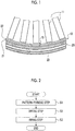
- Fig. 1 is a diagram showing the schematic structure of a shroud on which an abradable coating is implemented by an implementing method according to this embodiment.
- Fig. 2 is a flowchart relating to a method for implementing an abradable coating according to this embodiment.
- a method for implementing an abradable coating according to this embodiment is applied to a shroud, which is to be provided in a gas turbine, such as a gas turbine generator or a gas turbine engine, as an implementation object.
- a shroud 10 will be briefly described prior to the method for implementing an abradable coating.
- the shroud 10 is a casing provided to surround the radially outside of a plurality of rotor blades 11 that are arranged on a rotating shaft at predetermined intervals in a circumferential direction.
- high-temperature working fluid such as combustion gas
- circulates in the shroud 10 and the plurality of rotor blades 11 are rotated about the rotating shaft by the working fluid.
- the shroud 10 is a stationary member, and the plurality of rotor blades 11 are rotatable members that are rotated about the rotating shaft.
- a clearance 15 is formed between the shroud 10 and each rotor blade 11 in the radial direction of the rotating shaft.
- the shroud 10 includes a shroud body 20, a thermal barrier coating layer (ceramic layer) 21, and an abradable coating layer 22.
- the shroud body 20 is made of, for example, a heat-resistant metallic material, such as a Ni-based superalloy, and a cooling flow passage 25 is formed in the shroud body 20.
- a cooling medium such as cooling air, circulates in the cooling flow passage 25 so as to cool the shroud body 20 that is heated by high-temperature working fluid circulating in the shroud 10.
- the cooling flow passage 25 can be used in a method for implementing an abradable coating to be described later.
- the thermal barrier coating layer (TBC: thermal barrier coating) 21 is formed on the surface of the shroud body 20, that is, the surface of the shroud body 20 facing the rotor blades 11.
- the thermal barrier coating layer 21 is formed of a porous ceramic layer to inhibit heat from being input to the shroud body 20 from the high-temperature working fluid.
- a zirconia-based ceramic material which is an oxide-based ceramic material, is used for the thermal barrier coating layer 21, and ZrO 2 is used for the thermal barrier coating layer 21 in this embodiment.
- the porosity of the thermal barrier coating layer 21 is in the range of, for example, 5% to 15%, and is 10% in this embodiment.
- the thermal barrier coating layer 21 is evenly formed on the surface of the shroud body 20 as a layer having a uniform thickness by, for example, ceramic spraying (APS: atmospheric plasma spraying).
- the abradable coating layer 22 is formed on the surface of the thermal barrier coating layer 21.
- the abradable coating layer 22 is a seal material that is used to inhibit working fluid from leaking from the clearance 15 formed between the shroud 10 and each rotor blade 11, and is subjected to free-cutting by each rotor blade 11. Since the abradable coating layer 22 is formed in the shape of a fin protruding from the thermal barrier coating layer 21, a predetermined pattern is formed on the thermal barrier coating layer 21. For example, a wavy fin is used as the pattern, but the shape of the pattern is not limited thereto and may be any shape that inhibits working fluid from leaking.
- the same type of ceramic material as the thermal barrier coating layer 21 is used for the abradable coating layer 22.
- a zirconia-based ceramic material is used for the abradable coating layer 22, and ZrO 2 is used for the abradable coating layer 22 in this embodiment.
- the porosity of the abradable coating layer 22 is in the range of, for example, 10% to 40%, and is 20% in this embodiment.
- the abradable coating layer 22 is formed on the surface of the thermal barrier coating layer 21 by a method for implementing an abradable coating to be described later.
- the shroud body 20 on which the thermal barrier coating layer 21 is implemented is applied as a base material and the abradable coating layer 22 is formed on the surface of the thermal barrier coating layer 21.
- the shroud body 20 on which the thermal barrier coating layer 21 is implemented is applied as the base material in this embodiment, but the present invention is not limited to this structure and a porous ceramic material may be applied as the base material.
- Step S1 pattern-forming step
- the slurry which is used in the pattern-forming step S1, will be described.
- the slurry contains ceramic particles, a solvent, a binder, and a dispersant.
- the ceramic particles include coarse particles and fine particles, and zirconia-based (for example, ZrO 2 ) ceramic particles are used as either particles in this embodiment.
- V1 the volume of coarse particles
- V2 the volume of fine particles
- a ratio (V1/V2) of the volume of coarse particles to the volume of fine particles satisfies the range of "50/50 ⁇ V1/V2 ⁇ 90/10" and is about 7/3 in this embodiment.
- the average particle size of the coarse particles is in the range of 1 ⁇ m to 10 ⁇ m, and coarse particles having an average particle size of 3.4 ⁇ m are used in this embodiment.
- the average particle size of the fine particles is in the range of 0.01 ⁇ m to 1 ⁇ m, and fine particles having an average particle size of 0.1 ⁇ m are used in this embodiment.
- water such as distilled water
- the solvent is mixed so that the volume concentration of the ceramic particles in the slurry is in the range of 20 to 60 vol%. Since water, which is harder to be volatilized than other solvents, such as alcohol, is used as the solvent in this embodiment, a change in the viscosity or the like of the slurry over time is inhibited.
- polyvinyl alcohol PVA
- the binder is mixed so that the percentage by mass of the binder is in the range of 1 to 10 wt% with respect to the mass of the ceramic particles.
- an ammonium salt of a polycarboxylic acid is used as the dispersant, and the dispersant is mixed so that the percentage by mass of the dispersant is in the range of 0.1 to 0.5 wt% with respect to the mass of the ceramic particles.
- the viscosity of the slurry which is composed as described above, is 16.4 mPa ⁇ s in this embodiment.
- the slurry is an example and is not limited to the above-mentioned composition.
- a ratio of the coarse particles to the fine particles needs to be increased in a case in which an abradable coating layer 22 having higher porosity is required.
- the volume concentration of ceramic powder needs to be increased or the amount of the binder to be added needs to be increased in a case in which slurry having higher viscosity is required.
- a nozzle for discharging the slurry and a multi-axis robot for moving the nozzle are used. That is, in the pattern-forming step S1, while the slurry is discharged to the thermal barrier coating layer 21 from the nozzle, the nozzle is moved by the multi-axis robot to form a predetermined slurry pattern.
- a drying step S2 is performed subsequently.
- the solvent contained in the slurry pattern is volatilized through natural drying or drying by heating.
- a firing step S3 is performed subsequently.
- the slurry pattern formed on the surface of the thermal barrier coating layer 21 is sintered, so that the abradable coating layer 22 is formed.
- the firing step S3 only a portion of the thermal barrier coating layer 21 on which the slurry pattern is formed is directly heated by the flame of a burner or the like or is directly heated by laser irradiation.
- a cooling medium is made to circulate in the cooling flow passage 25 of the shroud body 20 to cool the shroud body 20 and the thermal barrier coating layer 21.
- the slurry pattern is heated to a firing temperature, so that the abradable coating layer 22 is formed on the thermal barrier coating layer 21.
- the slurry pattern is formed on the thermal barrier coating layer 21 and is then sintered, so that the abradable coating layer 22 can be formed on the thermal barrier coating layer 21.
- the abradable coating layer 22 having high free-cutting ability can be formed by simple steps, the implementation of an abradable coating can be streamlined.
- the slurry pattern can be formed on the porous thermal barrier coating layer 21. For this reason, ceramic particles contained in the slurry enter the pores of the thermal barrier coating layer 21 and the slurry pattern is fired in this state, so that the thermal barrier coating layer 21 and the abradable coating layer 22 can be firmly joined to each other.
- the thermal expansion coefficients of the thermal barrier coating layer 21 and the abradable coating layer 22 can be set to be equal to each other. For this reason, it is possible to inhibit the separation of the thermal barrier coating layer 21 and the abradable coating layer 22 that is caused by heat.
- a cooling medium can be made to circulate in the cooling flow passage 25 of the shroud body 20 during the firing of the slurry pattern. Accordingly, since it is possible to inhibit heat from being input to the shroud 10, it is possible to reduce the influence of heat on the shroud 10.
- the nozzle and the multi-axis robot are used in the pattern-forming step S1 and a slurry pattern can be stably formed on the thermal barrier coating layer 21 by the multi-axis robot, productivity can be improved.
- slurry suitable for the pattern-forming step S1 can be used and the abradable coating layer 22 to be formed after the firing step S3 can be formed as an appropriate abradable coating layer.
- the change of the slurry over time can be inhibited. Accordingly, a slurry pattern can be stably formed during mass production. Further, since the solvent is consumables, running costs can be reduced in a case in which inexpensive water is used as the solvent.
- Yttria-stabilized zirconia is used as ceramic materials used for the thermal barrier coating layer 21 and the abradable coating layer 22 in this embodiment, but the ceramic materials are not limited thereto.
- alumina-based ceramic material or a rare-earth silicate-based ceramic material may be used.
- the entire shroud 10 may be put in a heating furnace and a method of heating the slurry pattern is not particularly limited.
- the nozzle and the multi-axis robot are used in the pattern-forming step S1 in this embodiment, but the present invention is not limited to this structure.
- slurry may be applied to the surface of the thermal barrier coating layer 21 and a die member may be pressed against the applied slurry to form a slurry pattern. Since a slurry pattern can be stably formed on the thermal barrier coating layer 21 by the die member, productivity can be improved even in this structure.
Landscapes
- Chemical & Material Sciences (AREA)
- Engineering & Computer Science (AREA)
- Mechanical Engineering (AREA)
- Materials Engineering (AREA)
- Chemical Kinetics & Catalysis (AREA)
- Metallurgy (AREA)
- Organic Chemistry (AREA)
- General Engineering & Computer Science (AREA)
- Physics & Mathematics (AREA)
- Plasma & Fusion (AREA)
- Combustion & Propulsion (AREA)
- Inorganic Chemistry (AREA)
- Wood Science & Technology (AREA)
- Life Sciences & Earth Sciences (AREA)
- Ceramic Engineering (AREA)
- Turbine Rotor Nozzle Sealing (AREA)
- Application Of Or Painting With Fluid Materials (AREA)
- Coating By Spraying Or Casting (AREA)
- Other Surface Treatments For Metallic Materials (AREA)
Abstract
Description
- The present invention relates to a method for implementing an abradable coating to be formed on the surface of a base material, such as a shroud, and a shroud.
- In the past, a coating, which includes a bond coat to be formed on the surface of a base material and a ceramic layer to be formed on the bond coat, has been known as a coating to be formed on a base material (for example, see PTL 1). The ceramic layer is formed in a predetermined pattern by plasma spraying that is performed on the base material while a mask is used.
- [PTL 1] Specification of
U.S. Unexamined Patent Application Publication No. 2005/0003172 - However, since the mask where slits for forming a predetermined pattern are formed is used in PTL 1, there is a possibility that the slits of the mask may be closed (clogged) in a case in which plasma spraying is performed. In this case, since the mask should be more often replaced, it is difficult to improve implementation efficiency.
- An object of the present invention is to provide a method for implementing an abradable coating, which can streamline the implementation of an abradable coating having high free-cutting ability, and a shroud.
- A method for implementing an abradable coating of the present invention includes a pattern-forming step of forming a slurry pattern on a surface of a base material by using slurry that contains ceramic particles and a solvent, and a firing step of forming an abradable coating layer by sintering the slurry pattern that is formed on the surface of the base material.
- According to this structure, the slurry pattern is formed on the base material and is then sintered, so that the abradable coating layer can be formed on the base material. For this reason, since a mask and the like do not need to be used and the abradable coating layer having high free-cutting ability can be formed by simple steps, the implementation of an abradable coating can be streamlined.
- Further, it is preferable that a porous ceramic layer is formed on the surface of the base material and, in the pattern-forming step, the slurry pattern is formed on the ceramic layer by using the slurry.
- According to this structure, the ceramic layer and the abradable coating layer can be firmly joined to each other. That is, since the ceramic layer is porous, a solvent contained in the slurry enters the pores of the ceramic layer and ceramic particles are flocculated on an interface between the ceramic layer and the slurry. Since the slurry pattern is fired in this state, the ceramic layer and the abradable coating layer are firmly joined to each other.
- Furthermore, it is preferable that a ceramic material contained in the ceramic layer and ceramic particles contained in the abradable coating layer are of the same type.
- According to this structure, the thermal expansion coefficients of the ceramic layer and the abradable coating layer can be set to be equal to each other. For this reason, it is possible to inhibit the separation of the ceramic layer and the abradable coating layer that is caused by heat.
- Moreover, it is preferable that the base material is a shroud in which a cooling flow passage is formed and, in the firing step, only a portion of the base material on which the slurry pattern is formed is heated and a cooling medium is made to circulate in the cooling flow passage.
- According to this structure, since it is possible to inhibit heat from being input to the shroud during the firing of the slurry pattern, it is possible to reduce the influence of heat on the shroud.
- Further, it is preferable that, in the pattern-forming step, while the slurry is discharged to the base material from a nozzle for discharging the slurry, the nozzle is moved by a multi-axis robot to form the slurry pattern.
- According to this structure, since the slurry pattern can be stably formed on the base material by the multi-axis robot, productivity can be improved.
- Furthermore, it is preferable that, in the pattern-forming step, the slurry is applied to the surface of the base material and a die member is pressed against the applied slurry to form the slurry pattern.
- According to this structure, since the slurry pattern can be stably formed on the base material by the die member, productivity can be improved.
- Moreover, it is preferable that the ceramic particles include coarse particles having a large particle size and fine particles having a particle size smaller than the particle size of the coarse particle and a ratio of the volume of the coarse particles to the volume of the fine particles satisfies a range of "50/50≤V1/V2≤90/10" in a case in which the volume of the coarse particles is denoted by V1 and the volume of the fine particles is denoted by V2.
- According to this structure, slurry suitable for the pattern-forming step can be used and the abradable coating layer to be formed after the firing step can be formed as an appropriate abradable coating layer. It is more preferable that a ratio of the volume of the coarse particles to the volume of the fine particles is about 7/3.
- Further, it is preferable that an average particle size of the coarse particles is in the range of 1 µm to 10 µm and an average particle size of the fine particles is in the range of 0.01 µm to 1 µm.
- According to this structure, slurry more suitable for the pattern-forming step can be used and the abradable coating layer to be formed after the firing step can be formed as a more appropriate abradable coating layer likewise.
- Furthermore, it is preferable that the solvent is water.
- According to this structure, since water, which is harder to be volatilized than other solvents, such as alcohol, the change of the slurry over time can be inhibited. For this reason, the slurry pattern can be stably formed during mass production. Further, since the solvent is consumables, running costs can be reduced in a case in which inexpensive water is used as the solvent.
- A shroud of the present invention is a shroud that includes a porous ceramic layer formed on a surface thereof facing a rotor blade. The shroud includes an abradable coating layer that is formed on the surface of the ceramic layer. A ceramic material contained in the ceramic layer and a ceramic material contained in the abradable coating layer are of the same type.
- According to this structure, the ceramic layer and the abradable coating layer can be firmly joined to each other. Further, since the thermal expansion coefficients of the ceramic layer and the abradable coating layer can be set to be equal to each other, it is possible to inhibit the separation of the ceramic layer and the abradable coating layer that is caused by heat. For this reason, a highly-reliable abradable coating layer can be formed.
-
-
Fig. 1 is a diagram showing the schematic structure of a shroud on which an abradable coating is implemented by an implementing method according to this embodiment. -
Fig. 2 is a flowchart relating to a method for implementing an abradable coating according to this embodiment. - An embodiment of the present invention will be described in detail below with reference to the drawings. The present invention is not limited by this embodiment. Further, components of the following embodiment include components that can be substituted and easily supposed by those skilled in the art or substantially the same components as the components of the following embodiment. Furthermore, components described below can be appropriately combined. In a case in which there are a plurality of embodiments, the respective embodiments can also be combined.
-
Fig. 1 is a diagram showing the schematic structure of a shroud on which an abradable coating is implemented by an implementing method according to this embodiment.Fig. 2 is a flowchart relating to a method for implementing an abradable coating according to this embodiment. - A method for implementing an abradable coating according to this embodiment is applied to a shroud, which is to be provided in a gas turbine, such as a gas turbine generator or a gas turbine engine, as an implementation object. First, a
shroud 10 will be briefly described prior to the method for implementing an abradable coating. - The
shroud 10 is a casing provided to surround the radially outside of a plurality ofrotor blades 11 that are arranged on a rotating shaft at predetermined intervals in a circumferential direction. For example, high-temperature working fluid, such as combustion gas, circulates in theshroud 10, and the plurality ofrotor blades 11 are rotated about the rotating shaft by the working fluid. That is, theshroud 10 is a stationary member, and the plurality ofrotor blades 11 are rotatable members that are rotated about the rotating shaft. Further, aclearance 15 is formed between theshroud 10 and eachrotor blade 11 in the radial direction of the rotating shaft. - The
shroud 10 includes ashroud body 20, a thermal barrier coating layer (ceramic layer) 21, and anabradable coating layer 22. Theshroud body 20 is made of, for example, a heat-resistant metallic material, such as a Ni-based superalloy, and acooling flow passage 25 is formed in theshroud body 20. A cooling medium, such as cooling air, circulates in thecooling flow passage 25 so as to cool theshroud body 20 that is heated by high-temperature working fluid circulating in theshroud 10. Further, thecooling flow passage 25 can be used in a method for implementing an abradable coating to be described later. - The thermal barrier coating layer (TBC: thermal barrier coating) 21 is formed on the surface of the
shroud body 20, that is, the surface of theshroud body 20 facing therotor blades 11. The thermalbarrier coating layer 21 is formed of a porous ceramic layer to inhibit heat from being input to theshroud body 20 from the high-temperature working fluid. - A zirconia-based ceramic material, which is an oxide-based ceramic material, is used for the thermal
barrier coating layer 21, and ZrO2 is used for the thermalbarrier coating layer 21 in this embodiment. The porosity of the thermalbarrier coating layer 21 is in the range of, for example, 5% to 15%, and is 10% in this embodiment. The thermalbarrier coating layer 21 is evenly formed on the surface of theshroud body 20 as a layer having a uniform thickness by, for example, ceramic spraying (APS: atmospheric plasma spraying). - The
abradable coating layer 22 is formed on the surface of the thermalbarrier coating layer 21. Theabradable coating layer 22 is a seal material that is used to inhibit working fluid from leaking from theclearance 15 formed between theshroud 10 and eachrotor blade 11, and is subjected to free-cutting by eachrotor blade 11. Since theabradable coating layer 22 is formed in the shape of a fin protruding from the thermalbarrier coating layer 21, a predetermined pattern is formed on the thermalbarrier coating layer 21. For example, a wavy fin is used as the pattern, but the shape of the pattern is not limited thereto and may be any shape that inhibits working fluid from leaking. - The same type of ceramic material as the thermal
barrier coating layer 21 is used for theabradable coating layer 22. For example, a zirconia-based ceramic material is used for theabradable coating layer 22, and ZrO2 is used for theabradable coating layer 22 in this embodiment. The porosity of theabradable coating layer 22 is in the range of, for example, 10% to 40%, and is 20% in this embodiment. Theabradable coating layer 22 is formed on the surface of the thermalbarrier coating layer 21 by a method for implementing an abradable coating to be described later. - Next, a method for implementing an abradable coating will be described with reference to
Fig. 2 . In the implementing method of this embodiment, theshroud body 20 on which the thermalbarrier coating layer 21 is implemented is applied as a base material and theabradable coating layer 22 is formed on the surface of the thermalbarrier coating layer 21. Theshroud body 20 on which the thermalbarrier coating layer 21 is implemented is applied as the base material in this embodiment, but the present invention is not limited to this structure and a porous ceramic material may be applied as the base material. - In the implementing method of this embodiment, first, a slurry pattern is formed on the surface of the thermal
barrier coating layer 21 by using slurry (Step S1: pattern-forming step). - Here, the slurry, which is used in the pattern-forming step S1, will be described. The slurry contains ceramic particles, a solvent, a binder, and a dispersant.
- The ceramic particles include coarse particles and fine particles, and zirconia-based (for example, ZrO2) ceramic particles are used as either particles in this embodiment. In a case in which the volume of coarse particles is denoted by V1 and the volume of fine particles is denoted by V2, a ratio (V1/V2) of the volume of coarse particles to the volume of fine particles satisfies the range of "50/50≤V1/V2≤90/10" and is about 7/3 in this embodiment. Further, the average particle size of the coarse particles is in the range of 1 µm to 10 µm, and coarse particles having an average particle size of 3.4 µm are used in this embodiment. The average particle size of the fine particles is in the range of 0.01 µm to 1 µm, and fine particles having an average particle size of 0.1 µm are used in this embodiment.
- For example, water, such as distilled water, is used as the solvent, and the solvent is mixed so that the volume concentration of the ceramic particles in the slurry is in the range of 20 to 60 vol%. Since water, which is harder to be volatilized than other solvents, such as alcohol, is used as the solvent in this embodiment, a change in the viscosity or the like of the slurry over time is inhibited.
- For example, polyvinyl alcohol (PVA) is used as the binder, and the binder is mixed so that the percentage by mass of the binder is in the range of 1 to 10 wt% with respect to the mass of the ceramic particles. For example, an ammonium salt of a polycarboxylic acid is used as the dispersant, and the dispersant is mixed so that the percentage by mass of the dispersant is in the range of 0.1 to 0.5 wt% with respect to the mass of the ceramic particles.
- The viscosity of the slurry, which is composed as described above, is 16.4 mPa·s in this embodiment. The slurry is an example and is not limited to the above-mentioned composition. For example, a ratio of the coarse particles to the fine particles needs to be increased in a case in which an
abradable coating layer 22 having higher porosity is required. For example, the volume concentration of ceramic powder needs to be increased or the amount of the binder to be added needs to be increased in a case in which slurry having higher viscosity is required. - In a case in which a slurry pattern is formed on the thermal
barrier coating layer 21 by using the slurry, a nozzle for discharging the slurry and a multi-axis robot for moving the nozzle are used. That is, in the pattern-forming step S1, while the slurry is discharged to the thermalbarrier coating layer 21 from the nozzle, the nozzle is moved by the multi-axis robot to form a predetermined slurry pattern. - Here, since the slurry is applied to the porous thermal
barrier coating layer 21, a part of the solvent contained in the slurry reaches the thermalbarrier coating layer 21. In this case, some ceramic particles enter the pores of the thermalbarrier coating layer 21 with the movement of the solvent. After the pattern-forming step S1, a drying step S2 is performed subsequently. - In the drying step S2, the solvent contained in the slurry pattern is volatilized through natural drying or drying by heating. After the drying step S2, a firing step S3 is performed subsequently.
- In the firing step S3, the slurry pattern formed on the surface of the thermal
barrier coating layer 21 is sintered, so that theabradable coating layer 22 is formed. Specifically, in the firing step S3, only a portion of the thermalbarrier coating layer 21 on which the slurry pattern is formed is directly heated by the flame of a burner or the like or is directly heated by laser irradiation. In this case, in the firing step S3, a cooling medium is made to circulate in thecooling flow passage 25 of theshroud body 20 to cool theshroud body 20 and the thermalbarrier coating layer 21. Accordingly, in the firing step S3, the slurry pattern is heated to a firing temperature, so that theabradable coating layer 22 is formed on the thermalbarrier coating layer 21. - According to this embodiment, as described above, the slurry pattern is formed on the thermal
barrier coating layer 21 and is then sintered, so that theabradable coating layer 22 can be formed on the thermalbarrier coating layer 21. For this reason, since a mask and the like do not need to be used and theabradable coating layer 22 having high free-cutting ability can be formed by simple steps, the implementation of an abradable coating can be streamlined. - Further, according to this embodiment, the slurry pattern can be formed on the porous thermal
barrier coating layer 21. For this reason, ceramic particles contained in the slurry enter the pores of the thermalbarrier coating layer 21 and the slurry pattern is fired in this state, so that the thermalbarrier coating layer 21 and theabradable coating layer 22 can be firmly joined to each other. - Furthermore, according to this embodiment, since the ceramic material of the thermal
barrier coating layer 21 and the ceramic material of theabradable coating layer 22 can be of the same type, the thermal expansion coefficients of the thermalbarrier coating layer 21 and theabradable coating layer 22 can be set to be equal to each other. For this reason, it is possible to inhibit the separation of the thermalbarrier coating layer 21 and theabradable coating layer 22 that is caused by heat. - Moreover, according to this embodiment, a cooling medium can be made to circulate in the
cooling flow passage 25 of theshroud body 20 during the firing of the slurry pattern. Accordingly, since it is possible to inhibit heat from being input to theshroud 10, it is possible to reduce the influence of heat on theshroud 10. - Further, according to this embodiment, since the nozzle and the multi-axis robot are used in the pattern-forming step S1 and a slurry pattern can be stably formed on the thermal
barrier coating layer 21 by the multi-axis robot, productivity can be improved. - Furthermore, according to this embodiment, since the above-mentioned slurry is used, slurry suitable for the pattern-forming step S1 can be used and the
abradable coating layer 22 to be formed after the firing step S3 can be formed as an appropriate abradable coating layer. - Moreover, according to this embodiment, since water is used as the solvent, the change of the slurry over time can be inhibited. Accordingly, a slurry pattern can be stably formed during mass production. Further, since the solvent is consumables, running costs can be reduced in a case in which inexpensive water is used as the solvent.
- Yttria-stabilized zirconia (YSZ) is used as ceramic materials used for the thermal
barrier coating layer 21 and theabradable coating layer 22 in this embodiment, but the ceramic materials are not limited thereto. For example, an alumina-based ceramic material or a rare-earth silicate-based ceramic material may be used. - Further, only a portion of the thermal barrier coating layer on which the slurry pattern is formed is heated in this embodiment, but the
entire shroud 10 may be put in a heating furnace and a method of heating the slurry pattern is not particularly limited. - Furthermore, the nozzle and the multi-axis robot are used in the pattern-forming step S1 in this embodiment, but the present invention is not limited to this structure. For example, in the pattern-forming step S1, slurry may be applied to the surface of the thermal
barrier coating layer 21 and a die member may be pressed against the applied slurry to form a slurry pattern. Since a slurry pattern can be stably formed on the thermalbarrier coating layer 21 by the die member, productivity can be improved even in this structure. -
- 10:
- shroud
- 11:
- rotor blade
- 15:
- clearance
- 20:
- shroud body
- 21:
- thermal barrier coating layer
- 22:
- abradable coating layer
- 25:
- cooling flow passage
Claims (10)
- A method for implementing an abradable coating, the method comprising:a pattern-forming step of forming a slurry pattern on a surface of a base material by using slurry that contains ceramic particles and a solvent; anda firing step of forming an abradable coating layer by sintering the slurry pattern that is formed on the surface of the base material.
- The method for implementing an abradable coating according to Claim 1,
wherein a porous ceramic layer is formed on the surface of the base material, and
in the pattern-forming step, the slurry pattern is formed on the ceramic layer by using the slurry. - The method for implementing an abradable coating according to Claim 2,
wherein a ceramic material contained in the ceramic layer and ceramic particles contained in the abradable coating layer are of the same type. - The method for implementing an abradable coating according to any one of Claims 1 to 3,
wherein the base material is a shroud in which a cooling flow passage is formed, and
in the firing step, only a portion of the base material on which the slurry pattern is formed is heated and a cooling medium is made to circulate in the cooling flow passage. - The method for implementing an abradable coating according to any one of Claims 1 to 4,
wherein in the pattern-forming step, while the slurry is discharged to the base material from a nozzle for discharging the slurry, the nozzle is moved by a multi-axis robot to form the slurry pattern. - The method for implementing an abradable coating according to any one of Claims 1 to 4,
wherein in the pattern-forming step, the slurry is applied to the surface of the base material and a die member is pressed against the applied slurry to form the slurry pattern. - The method for implementing an abradable coating according to any one of Claims 1 to 6,
wherein the ceramic particles include coarse particles having a large particle size and fine particles having a particle size smaller than the particle size of the coarse particle, and
a ratio of the volume of the coarse particles to the volume of the fine particles satisfies a range of "50/50≤V1/V2≤90/10" in a case in which the volume of the coarse particles is denoted by V1 and the volume of the fine particles is denoted by V2. - The method for implementing an abradable coating according to Claim 7,
wherein an average particle size of the coarse particles is in the range of 1 µm to 10 µm, and
an average particle size of the fine particles is in the range of 0.01 µm to 1 µm. - The method for implementing an abradable coating according to any one of Claims 1 to 8,
wherein the solvent is water. - A shroud that includes a porous ceramic layer formed on a surface thereof facing a rotor blade, the shroud comprising:an abradable coating layer that is formed on the surface of the ceramic layer,wherein a ceramic material contained in the ceramic layer and a ceramic material contained in the abradable coating layer are of the same type.
Applications Claiming Priority (2)
| Application Number | Priority Date | Filing Date | Title |
|---|---|---|---|
| JP2016020202A JP6632407B2 (en) | 2016-02-04 | 2016-02-04 | Construction method of abradable coating |
| PCT/JP2017/000116 WO2017134976A1 (en) | 2016-02-04 | 2017-01-05 | Shroud and method for implementing abradable coating |
Publications (3)
| Publication Number | Publication Date |
|---|---|
| EP3369487A1 true EP3369487A1 (en) | 2018-09-05 |
| EP3369487A4 EP3369487A4 (en) | 2018-11-07 |
| EP3369487B1 EP3369487B1 (en) | 2020-05-27 |
Family
ID=59499488
Family Applications (1)
| Application Number | Title | Priority Date | Filing Date |
|---|---|---|---|
| EP17747140.6A Active EP3369487B1 (en) | 2016-02-04 | 2017-01-05 | Shroud and method for implementing abradable coating |
Country Status (5)
| Country | Link |
|---|---|
| US (1) | US10465548B2 (en) |
| EP (1) | EP3369487B1 (en) |
| JP (1) | JP6632407B2 (en) |
| CA (1) | CA3013304C (en) |
| WO (1) | WO2017134976A1 (en) |
Families Citing this family (2)
| Publication number | Priority date | Publication date | Assignee | Title |
|---|---|---|---|---|
| JP6896385B2 (en) * | 2016-08-10 | 2021-06-30 | 三菱重工航空エンジン株式会社 | How to apply abradable coating |
| JP2023133660A (en) * | 2022-03-14 | 2023-09-27 | 三菱重工業株式会社 | High-temperature parts, rotating machinery, and manufacturing methods for high-temperature parts |
Family Cites Families (14)
| Publication number | Priority date | Publication date | Assignee | Title |
|---|---|---|---|---|
| JPH03214440A (en) * | 1990-01-19 | 1991-09-19 | Nippon Sheet Glass Co Ltd | Production of optical disk substrate |
| US6733907B2 (en) | 1998-03-27 | 2004-05-11 | Siemens Westinghouse Power Corporation | Hybrid ceramic material composed of insulating and structural ceramic layers |
| US20050003172A1 (en) | 2002-12-17 | 2005-01-06 | General Electric Company | 7FAstage 1 abradable coatings and method for making same |
| ES2340037T3 (en) * | 2003-12-17 | 2010-05-28 | Sulzer Metco (Us) Inc. | TURBO MACHINE WITH ABRASION CERAMIC LAYER .. |
| JP2010151267A (en) * | 2008-12-26 | 2010-07-08 | Hitachi Ltd | Seal structure and gas turbine using the same |
| US20120107103A1 (en) * | 2010-09-28 | 2012-05-03 | Yoshitaka Kojima | Gas turbine shroud with ceramic abradable layer |
| JP5597174B2 (en) * | 2011-09-20 | 2014-10-01 | 株式会社日立製作所 | Member having abradable coating and gas turbine |
| JP2013071068A (en) * | 2011-09-28 | 2013-04-22 | Daihatsu Motor Co Ltd | Apparatus for coating high viscosity fluid |
| US9289917B2 (en) | 2013-10-01 | 2016-03-22 | General Electric Company | Method for 3-D printing a pattern for the surface of a turbine shroud |
| JP6240779B2 (en) * | 2013-12-12 | 2017-11-29 | ゼネラル・エレクトリック・カンパニイ | Method of depositing an abradable film under a polymer gel |
| CN105814007B (en) * | 2013-12-12 | 2019-05-07 | 通用电气公司 | Method for depositing abradable coatings in polymer gel form |
| US20150354392A1 (en) | 2014-06-10 | 2015-12-10 | General Electric Company | Abradable coatings |
| US20150354394A1 (en) | 2014-06-10 | 2015-12-10 | General Electric Company | Shroud abradable coatings and methods of manufacturing |
| US20150354393A1 (en) * | 2014-06-10 | 2015-12-10 | General Electric Company | Methods of manufacturing a shroud abradable coating |
-
2016
- 2016-02-04 JP JP2016020202A patent/JP6632407B2/en active Active
-
2017
- 2017-01-05 EP EP17747140.6A patent/EP3369487B1/en active Active
- 2017-01-05 WO PCT/JP2017/000116 patent/WO2017134976A1/en not_active Ceased
- 2017-01-05 US US15/781,996 patent/US10465548B2/en active Active
- 2017-01-05 CA CA3013304A patent/CA3013304C/en active Active
Also Published As
| Publication number | Publication date |
|---|---|
| JP6632407B2 (en) | 2020-01-22 |
| US10465548B2 (en) | 2019-11-05 |
| JP2017137539A (en) | 2017-08-10 |
| CA3013304C (en) | 2020-10-27 |
| EP3369487A4 (en) | 2018-11-07 |
| WO2017134976A1 (en) | 2017-08-10 |
| US20180363487A1 (en) | 2018-12-20 |
| EP3369487B1 (en) | 2020-05-27 |
| CA3013304A1 (en) | 2017-08-10 |
Similar Documents
| Publication | Publication Date | Title |
|---|---|---|
| RU2330162C2 (en) | High temperature foliated system for heat removal and method for its production (versions) | |
| EP1959099B1 (en) | A Method for Manufacturing a Member Coated with a Thermal Barrier | |
| US10989066B2 (en) | Abradable coating made of a material having a low surface roughness | |
| EP2113586A2 (en) | Low cost non-line-of-sight portective coatings | |
| JP2011507791A (en) | How to repair a barrier coating | |
| JP2006348942A (en) | Ceramic abradable material containing alumina dopant | |
| JP2003129210A (en) | Heat-insulating coating material, gas turbine member, and gas turbine | |
| JP2003160852A (en) | Thermal insulating coating material, manufacturing method therefor, turbine member and gas turbine | |
| US11085326B2 (en) | Gas turbine hot part and gas turbine | |
| JPWO2016129521A1 (en) | Manufacturing method of thermal barrier coating | |
| US10465548B2 (en) | Shroud and method for implementing abradable coating | |
| JP7045236B2 (en) | Thermal barrier coatings, turbine components and gas turbines | |
| JP6976406B2 (en) | Self-supporting ceramic seals for gas turbines and their forming methods | |
| US20190277143A1 (en) | High-temperature component for gas turbine, gas turbine blade and gas turbine | |
| US10994301B2 (en) | Method for constructing abradable coating, and shroud | |
| WO2018047523A1 (en) | Coating method, coating film, and turbine shroud | |
| US11319257B2 (en) | Ceramic heat shields having surface infiltration for preventing corrosion and erosion attacks | |
| JP6877217B2 (en) | Manufacturing method of heat shield coating, turbine blade and heat shield coating | |
| JP7122926B2 (en) | Method for manufacturing turbine components |
Legal Events
| Date | Code | Title | Description |
|---|---|---|---|
| STAA | Information on the status of an ep patent application or granted ep patent |
Free format text: STATUS: THE INTERNATIONAL PUBLICATION HAS BEEN MADE |
|
| PUAI | Public reference made under article 153(3) epc to a published international application that has entered the european phase |
Free format text: ORIGINAL CODE: 0009012 |
|
| STAA | Information on the status of an ep patent application or granted ep patent |
Free format text: STATUS: REQUEST FOR EXAMINATION WAS MADE |
|
| 17P | Request for examination filed |
Effective date: 20180529 |
|
| AK | Designated contracting states |
Kind code of ref document: A1 Designated state(s): AL AT BE BG CH CY CZ DE DK EE ES FI FR GB GR HR HU IE IS IT LI LT LU LV MC MK MT NL NO PL PT RO RS SE SI SK SM TR |
|
| AX | Request for extension of the european patent |
Extension state: BA ME |
|
| A4 | Supplementary search report drawn up and despatched |
Effective date: 20181009 |
|
| RIC1 | Information provided on ipc code assigned before grant |
Ipc: C23C 4/18 20060101ALI20181003BHEP Ipc: F01D 25/00 20060101ALI20181003BHEP Ipc: C23C 4/10 20160101ALI20181003BHEP Ipc: B05D 7/24 20060101AFI20181003BHEP Ipc: C23C 4/134 20160101ALI20181003BHEP Ipc: C23C 28/04 20060101ALI20181003BHEP Ipc: C23C 26/00 20060101ALI20181003BHEP Ipc: F01D 11/12 20060101ALI20181003BHEP Ipc: F01D 9/04 20060101ALI20181003BHEP Ipc: B05D 7/14 20060101ALI20181003BHEP Ipc: C23C 28/00 20060101ALI20181003BHEP Ipc: B05D 3/02 20060101ALI20181003BHEP Ipc: C23C 24/08 20060101ALI20181003BHEP Ipc: F02C 7/00 20060101ALI20181003BHEP Ipc: F02C 7/28 20060101ALI20181003BHEP Ipc: C23C 4/01 20160101ALI20181003BHEP |
|
| DAV | Request for validation of the european patent (deleted) | ||
| DAX | Request for extension of the european patent (deleted) | ||
| STAA | Information on the status of an ep patent application or granted ep patent |
Free format text: STATUS: EXAMINATION IS IN PROGRESS |
|
| 17Q | First examination report despatched |
Effective date: 20190614 |
|
| REG | Reference to a national code |
Ref country code: DE Ref legal event code: R079 Ref document number: 602017017380 Country of ref document: DE Free format text: PREVIOUS MAIN CLASS: B05D0007240000 Ipc: C23C0004100000 |
|
| RIC1 | Information provided on ipc code assigned before grant |
Ipc: C23C 4/10 20160101AFI20191128BHEP Ipc: C23C 24/08 20060101ALI20191128BHEP Ipc: C23C 26/00 20060101ALI20191128BHEP Ipc: C23C 4/01 20160101ALI20191128BHEP Ipc: C23C 4/134 20160101ALI20191128BHEP Ipc: C23C 4/18 20060101ALI20191128BHEP Ipc: C23C 28/04 20060101ALI20191128BHEP |
|
| GRAP | Despatch of communication of intention to grant a patent |
Free format text: ORIGINAL CODE: EPIDOSNIGR1 |
|
| STAA | Information on the status of an ep patent application or granted ep patent |
Free format text: STATUS: GRANT OF PATENT IS INTENDED |
|
| INTG | Intention to grant announced |
Effective date: 20200107 |
|
| GRAS | Grant fee paid |
Free format text: ORIGINAL CODE: EPIDOSNIGR3 |
|
| GRAA | (expected) grant |
Free format text: ORIGINAL CODE: 0009210 |
|
| STAA | Information on the status of an ep patent application or granted ep patent |
Free format text: STATUS: THE PATENT HAS BEEN GRANTED |
|
| AK | Designated contracting states |
Kind code of ref document: B1 Designated state(s): AL AT BE BG CH CY CZ DE DK EE ES FI FR GB GR HR HU IE IS IT LI LT LU LV MC MK MT NL NO PL PT RO RS SE SI SK SM TR |
|
| RAP1 | Party data changed (applicant data changed or rights of an application transferred) |
Owner name: MITSUBISHI HEAVY INDUSTRIES AERO ENGINES, LTD. |
|
| REG | Reference to a national code |
Ref country code: GB Ref legal event code: FG4D |
|
| RIN1 | Information on inventor provided before grant (corrected) |
Inventor name: HANADA, TADAYUKI Inventor name: MATSUMOTO, MINEAKI Inventor name: KURIMURA, TAKAYUKI Inventor name: TAMUGI, AZUSA |
|
| REG | Reference to a national code |
Ref country code: CH Ref legal event code: EP |
|
| REG | Reference to a national code |
Ref country code: AT Ref legal event code: REF Ref document number: 1274634 Country of ref document: AT Kind code of ref document: T Effective date: 20200615 |
|
| REG | Reference to a national code |
Ref country code: DE Ref legal event code: R096 Ref document number: 602017017380 Country of ref document: DE |
|
| REG | Reference to a national code |
Ref country code: LT Ref legal event code: MG4D |
|
| PG25 | Lapsed in a contracting state [announced via postgrant information from national office to epo] |
Ref country code: FI Free format text: LAPSE BECAUSE OF FAILURE TO SUBMIT A TRANSLATION OF THE DESCRIPTION OR TO PAY THE FEE WITHIN THE PRESCRIBED TIME-LIMIT Effective date: 20200527 Ref country code: NO Free format text: LAPSE BECAUSE OF FAILURE TO SUBMIT A TRANSLATION OF THE DESCRIPTION OR TO PAY THE FEE WITHIN THE PRESCRIBED TIME-LIMIT Effective date: 20200827 Ref country code: GR Free format text: LAPSE BECAUSE OF FAILURE TO SUBMIT A TRANSLATION OF THE DESCRIPTION OR TO PAY THE FEE WITHIN THE PRESCRIBED TIME-LIMIT Effective date: 20200828 Ref country code: SE Free format text: LAPSE BECAUSE OF FAILURE TO SUBMIT A TRANSLATION OF THE DESCRIPTION OR TO PAY THE FEE WITHIN THE PRESCRIBED TIME-LIMIT Effective date: 20200527 Ref country code: LT Free format text: LAPSE BECAUSE OF FAILURE TO SUBMIT A TRANSLATION OF THE DESCRIPTION OR TO PAY THE FEE WITHIN THE PRESCRIBED TIME-LIMIT Effective date: 20200527 Ref country code: IS Free format text: LAPSE BECAUSE OF FAILURE TO SUBMIT A TRANSLATION OF THE DESCRIPTION OR TO PAY THE FEE WITHIN THE PRESCRIBED TIME-LIMIT Effective date: 20200927 Ref country code: PT Free format text: LAPSE BECAUSE OF FAILURE TO SUBMIT A TRANSLATION OF THE DESCRIPTION OR TO PAY THE FEE WITHIN THE PRESCRIBED TIME-LIMIT Effective date: 20200928 |
|
| REG | Reference to a national code |
Ref country code: NL Ref legal event code: MP Effective date: 20200527 |
|
| PG25 | Lapsed in a contracting state [announced via postgrant information from national office to epo] |
Ref country code: RS Free format text: LAPSE BECAUSE OF FAILURE TO SUBMIT A TRANSLATION OF THE DESCRIPTION OR TO PAY THE FEE WITHIN THE PRESCRIBED TIME-LIMIT Effective date: 20200527 Ref country code: HR Free format text: LAPSE BECAUSE OF FAILURE TO SUBMIT A TRANSLATION OF THE DESCRIPTION OR TO PAY THE FEE WITHIN THE PRESCRIBED TIME-LIMIT Effective date: 20200527 Ref country code: LV Free format text: LAPSE BECAUSE OF FAILURE TO SUBMIT A TRANSLATION OF THE DESCRIPTION OR TO PAY THE FEE WITHIN THE PRESCRIBED TIME-LIMIT Effective date: 20200527 Ref country code: BG Free format text: LAPSE BECAUSE OF FAILURE TO SUBMIT A TRANSLATION OF THE DESCRIPTION OR TO PAY THE FEE WITHIN THE PRESCRIBED TIME-LIMIT Effective date: 20200827 |
|
| REG | Reference to a national code |
Ref country code: AT Ref legal event code: MK05 Ref document number: 1274634 Country of ref document: AT Kind code of ref document: T Effective date: 20200527 |
|
| PG25 | Lapsed in a contracting state [announced via postgrant information from national office to epo] |
Ref country code: NL Free format text: LAPSE BECAUSE OF FAILURE TO SUBMIT A TRANSLATION OF THE DESCRIPTION OR TO PAY THE FEE WITHIN THE PRESCRIBED TIME-LIMIT Effective date: 20200527 Ref country code: AL Free format text: LAPSE BECAUSE OF FAILURE TO SUBMIT A TRANSLATION OF THE DESCRIPTION OR TO PAY THE FEE WITHIN THE PRESCRIBED TIME-LIMIT Effective date: 20200527 |
|
| PG25 | Lapsed in a contracting state [announced via postgrant information from national office to epo] |
Ref country code: SM Free format text: LAPSE BECAUSE OF FAILURE TO SUBMIT A TRANSLATION OF THE DESCRIPTION OR TO PAY THE FEE WITHIN THE PRESCRIBED TIME-LIMIT Effective date: 20200527 Ref country code: RO Free format text: LAPSE BECAUSE OF FAILURE TO SUBMIT A TRANSLATION OF THE DESCRIPTION OR TO PAY THE FEE WITHIN THE PRESCRIBED TIME-LIMIT Effective date: 20200527 Ref country code: IT Free format text: LAPSE BECAUSE OF FAILURE TO SUBMIT A TRANSLATION OF THE DESCRIPTION OR TO PAY THE FEE WITHIN THE PRESCRIBED TIME-LIMIT Effective date: 20200527 Ref country code: CZ Free format text: LAPSE BECAUSE OF FAILURE TO SUBMIT A TRANSLATION OF THE DESCRIPTION OR TO PAY THE FEE WITHIN THE PRESCRIBED TIME-LIMIT Effective date: 20200527 Ref country code: ES Free format text: LAPSE BECAUSE OF FAILURE TO SUBMIT A TRANSLATION OF THE DESCRIPTION OR TO PAY THE FEE WITHIN THE PRESCRIBED TIME-LIMIT Effective date: 20200527 Ref country code: EE Free format text: LAPSE BECAUSE OF FAILURE TO SUBMIT A TRANSLATION OF THE DESCRIPTION OR TO PAY THE FEE WITHIN THE PRESCRIBED TIME-LIMIT Effective date: 20200527 Ref country code: DK Free format text: LAPSE BECAUSE OF FAILURE TO SUBMIT A TRANSLATION OF THE DESCRIPTION OR TO PAY THE FEE WITHIN THE PRESCRIBED TIME-LIMIT Effective date: 20200527 Ref country code: AT Free format text: LAPSE BECAUSE OF FAILURE TO SUBMIT A TRANSLATION OF THE DESCRIPTION OR TO PAY THE FEE WITHIN THE PRESCRIBED TIME-LIMIT Effective date: 20200527 |
|
| PG25 | Lapsed in a contracting state [announced via postgrant information from national office to epo] |
Ref country code: PL Free format text: LAPSE BECAUSE OF FAILURE TO SUBMIT A TRANSLATION OF THE DESCRIPTION OR TO PAY THE FEE WITHIN THE PRESCRIBED TIME-LIMIT Effective date: 20200527 Ref country code: SK Free format text: LAPSE BECAUSE OF FAILURE TO SUBMIT A TRANSLATION OF THE DESCRIPTION OR TO PAY THE FEE WITHIN THE PRESCRIBED TIME-LIMIT Effective date: 20200527 |
|
| REG | Reference to a national code |
Ref country code: DE Ref legal event code: R097 Ref document number: 602017017380 Country of ref document: DE |
|
| PLBE | No opposition filed within time limit |
Free format text: ORIGINAL CODE: 0009261 |
|
| STAA | Information on the status of an ep patent application or granted ep patent |
Free format text: STATUS: NO OPPOSITION FILED WITHIN TIME LIMIT |
|
| 26N | No opposition filed |
Effective date: 20210302 |
|
| PG25 | Lapsed in a contracting state [announced via postgrant information from national office to epo] |
Ref country code: SI Free format text: LAPSE BECAUSE OF FAILURE TO SUBMIT A TRANSLATION OF THE DESCRIPTION OR TO PAY THE FEE WITHIN THE PRESCRIBED TIME-LIMIT Effective date: 20200527 |
|
| PG25 | Lapsed in a contracting state [announced via postgrant information from national office to epo] |
Ref country code: MC Free format text: LAPSE BECAUSE OF FAILURE TO SUBMIT A TRANSLATION OF THE DESCRIPTION OR TO PAY THE FEE WITHIN THE PRESCRIBED TIME-LIMIT Effective date: 20200527 |
|
| REG | Reference to a national code |
Ref country code: CH Ref legal event code: PL |
|
| PG25 | Lapsed in a contracting state [announced via postgrant information from national office to epo] |
Ref country code: LU Free format text: LAPSE BECAUSE OF NON-PAYMENT OF DUE FEES Effective date: 20210105 |
|
| REG | Reference to a national code |
Ref country code: BE Ref legal event code: MM Effective date: 20210131 |
|
| PG25 | Lapsed in a contracting state [announced via postgrant information from national office to epo] |
Ref country code: LI Free format text: LAPSE BECAUSE OF NON-PAYMENT OF DUE FEES Effective date: 20210131 Ref country code: CH Free format text: LAPSE BECAUSE OF NON-PAYMENT OF DUE FEES Effective date: 20210131 |
|
| PG25 | Lapsed in a contracting state [announced via postgrant information from national office to epo] |
Ref country code: IE Free format text: LAPSE BECAUSE OF NON-PAYMENT OF DUE FEES Effective date: 20210105 |
|
| PG25 | Lapsed in a contracting state [announced via postgrant information from national office to epo] |
Ref country code: BE Free format text: LAPSE BECAUSE OF NON-PAYMENT OF DUE FEES Effective date: 20210131 |
|
| PG25 | Lapsed in a contracting state [announced via postgrant information from national office to epo] |
Ref country code: CY Free format text: LAPSE BECAUSE OF FAILURE TO SUBMIT A TRANSLATION OF THE DESCRIPTION OR TO PAY THE FEE WITHIN THE PRESCRIBED TIME-LIMIT Effective date: 20200527 |
|
| PG25 | Lapsed in a contracting state [announced via postgrant information from national office to epo] |
Ref country code: HU Free format text: LAPSE BECAUSE OF FAILURE TO SUBMIT A TRANSLATION OF THE DESCRIPTION OR TO PAY THE FEE WITHIN THE PRESCRIBED TIME-LIMIT; INVALID AB INITIO Effective date: 20170105 |
|
| PG25 | Lapsed in a contracting state [announced via postgrant information from national office to epo] |
Ref country code: MK Free format text: LAPSE BECAUSE OF FAILURE TO SUBMIT A TRANSLATION OF THE DESCRIPTION OR TO PAY THE FEE WITHIN THE PRESCRIBED TIME-LIMIT Effective date: 20200527 |
|
| PG25 | Lapsed in a contracting state [announced via postgrant information from national office to epo] |
Ref country code: TR Free format text: LAPSE BECAUSE OF FAILURE TO SUBMIT A TRANSLATION OF THE DESCRIPTION OR TO PAY THE FEE WITHIN THE PRESCRIBED TIME-LIMIT Effective date: 20200527 |
|
| PG25 | Lapsed in a contracting state [announced via postgrant information from national office to epo] |
Ref country code: MT Free format text: LAPSE BECAUSE OF FAILURE TO SUBMIT A TRANSLATION OF THE DESCRIPTION OR TO PAY THE FEE WITHIN THE PRESCRIBED TIME-LIMIT Effective date: 20200527 |
|
| PGFP | Annual fee paid to national office [announced via postgrant information from national office to epo] |
Ref country code: GB Payment date: 20251127 Year of fee payment: 10 |
|
| PGFP | Annual fee paid to national office [announced via postgrant information from national office to epo] |
Ref country code: FR Payment date: 20251128 Year of fee payment: 10 |
|
| PGFP | Annual fee paid to national office [announced via postgrant information from national office to epo] |
Ref country code: DE Payment date: 20251203 Year of fee payment: 10 |