EP3368234B1 - Aufformdorn mit einer aufweitbaren umhüllung und giessmodell mit aufformdorn sowie verfahren zum giessen von metallen - Google Patents
Aufformdorn mit einer aufweitbaren umhüllung und giessmodell mit aufformdorn sowie verfahren zum giessen von metallen Download PDFInfo
- Publication number
- EP3368234B1 EP3368234B1 EP16782282.4A EP16782282A EP3368234B1 EP 3368234 B1 EP3368234 B1 EP 3368234B1 EP 16782282 A EP16782282 A EP 16782282A EP 3368234 B1 EP3368234 B1 EP 3368234B1
- Authority
- EP
- European Patent Office
- Prior art keywords
- casting
- mandrel
- moulding
- model
- riser
- Prior art date
- Legal status (The legal status is an assumption and is not a legal conclusion. Google has not performed a legal analysis and makes no representation as to the accuracy of the status listed.)
- Active
Links
- 238000005266 casting Methods 0.000 title claims description 83
- 238000000034 method Methods 0.000 title claims description 16
- 239000002184 metal Substances 0.000 title claims description 14
- 229910052751 metal Inorganic materials 0.000 title claims description 14
- 150000002739 metals Chemical class 0.000 title claims description 7
- 238000000465 moulding Methods 0.000 claims description 53
- 229910001338 liquidmetal Inorganic materials 0.000 claims description 7
- 238000004519 manufacturing process Methods 0.000 claims description 7
- 239000000463 material Substances 0.000 claims description 3
- 239000012528 membrane Substances 0.000 claims description 3
- 239000000203 mixture Substances 0.000 claims description 3
- 239000004033 plastic Substances 0.000 claims description 3
- 238000007711 solidification Methods 0.000 claims description 2
- 230000008023 solidification Effects 0.000 claims description 2
- 239000012778 molding material Substances 0.000 description 9
- 238000007493 shaping process Methods 0.000 description 7
- 238000006073 displacement reaction Methods 0.000 description 4
- 238000004140 cleaning Methods 0.000 description 3
- 230000002787 reinforcement Effects 0.000 description 2
- 238000000926 separation method Methods 0.000 description 2
- 230000015572 biosynthetic process Effects 0.000 description 1
- 230000006735 deficit Effects 0.000 description 1
- 238000011161 development Methods 0.000 description 1
- 230000018109 developmental process Effects 0.000 description 1
- 230000000694 effects Effects 0.000 description 1
- 238000005516 engineering process Methods 0.000 description 1
- 238000009499 grossing Methods 0.000 description 1
- 239000011810 insulating material Substances 0.000 description 1
- 239000007788 liquid Substances 0.000 description 1
- 239000011819 refractory material Substances 0.000 description 1
- 230000000630 rising effect Effects 0.000 description 1
Images



Classifications
-
- B—PERFORMING OPERATIONS; TRANSPORTING
- B22—CASTING; POWDER METALLURGY
- B22C—FOUNDRY MOULDING
- B22C9/00—Moulds or cores; Moulding processes
- B22C9/08—Features with respect to supply of molten metal, e.g. ingates, circular gates, skim gates
- B22C9/088—Feeder heads
Definitions
- the invention relates to a forming mandrel for attachment to a casting model which is molded into this during the production of a casting mold used in the casting, having a foot standing on the model surface of the casting model and a receiving area arranged on the foot for receiving a to be formed therein during the production of the casting mold Feeder, the feeder with a feeder opening formed in its bottom surface facing the casting model being plugged onto the forming mandrel before molding.
- the invention also relates to a casting model having a corresponding molding mandrel and a method for casting metals using a corresponding casting model.
- the feeders must be designed in such a way that the liquid metal fed into them solidifies later than the cast part, so that material can be transported to the cast part during the solidification process, which tightly feeds the cast part.
- the feeders consist of an exothermic and / or insulating material.
- the feeders are arranged with any geometric shape at the point of the later cast part to be fed on the casting model and are firmly molded in during the creation of the casting mold by compressing an introduced molding material.
- so-called forming mandrels are known which are attached to the model surface of the respective casting model.
- Such a forming mandrel with the generic features is for example in a design as a so-called spring mandrel from the DE 10 2010 022 834 B4 known, the technical background for the arrangement of feeders and the use of forming mandrels is also described in this publication. In this respect, the explanations in DE 10 2010 022 834 B4 incorporated by reference into the disclosure of the present application.
- a forming mandrel with the features of the preamble of claim 1 is also from WO 2005/051568 A1 known.
- feeder cores which are fixed to the feeder body on the underside of the feeder body facing the casting model, are made of a refractory material and have a passage opening through which the mold cavity formed by the casting model Casting mold rising hot metal flows into the inner cavity of the feeder body or from there back into the mold cavity of the casting mold.
- the breaker cores usually produced by shooting in a shooting machine, are disc-shaped, the passage opening being formed by a constriction in the disc-shaped breaker core body in order to create a predetermined breaking point for breaking off the feeder residue from the surface of the casting.
- Such an arrangement of the feeder with a breaker core is for example from WO 20091103539 A1 known.
- the feeder moves in the direction of the casting model when the feeder is molded in the casting mold due to the mold pressure exerted, the feeder, including a breaker core that may be attached to it, usually does not come to rest on the model surface, but remains in a more or less large one Stand at a distance from it.
- the remaining cavity is filled with the liquid metal during the casting process filled in so that the predetermined breaking point provided by the breaker core is at a corresponding distance from the surface of the cast part. The resulting, more or less large riser remnants must then be removed by extensive cleaning work.
- the invention is therefore based on the object of providing a forming mandrel for fixing a feeder during the molding process, by means of which the use of an additional breaker core or other components forming a constriction associated with the feeder opening is dispensed with and yet a smaller feeder neck and an associated simple one Separation of the feeder remainder near the casting surface is made possible.
- the basic idea of the invention initially provides a forming mandrel with the features mentioned at the outset, in which on the forming mandrel an elastically expandable, elastically expandable and end-side on the foot of the forming mandrel directly on the model surface, enclosing at least its foot and / or a part of its receiving area for the feeder Adjacent casing is attached in such a way that the casing expanded before the start of molding bridges a gap that still exists between the model surface and the bottom surface of the feeder after the molding of the feeder, so that after the casting model with the mandrel attached to it has been removed from the casting mold, one through the contour the widened envelope formed predetermined breaking point for a feeder remainder remaining after completion of the casting process.
- the embodiment of the forming mandrel according to the invention has the advantage that, due to the casing which adjoins the model surface at one end and which is expanded during the molding process, it follows After demolding the casting model including the forming mandrel on the surface of the later cast part, a constriction with approximately the diameter of the foot of the forming mandrel is formed as a predetermined breaking point for the later knocking off of the feeder remainder directly on the cast part surface. This means that any cleaning effort that may still be required for removing the remains of the feeder from the cast part is significantly reduced.
- the space between the envelope and the molding mandrel is connected to a feed line for a medium to be introduced into the space, whereby according to a further embodiment of the invention this feed line is also designed as a discharge line for the medium fed into the space can be.
- this feed line is also designed as a discharge line for the medium fed into the space can be.
- a separate discharge line for the medium introduced into the intermediate space is connected to the intermediate space.
- the elastically expandable sheath is designed as a membrane made from a suitable rubber or plastic mixture.
- the forming mandrel is designed as a rigid mandrel.
- the behavior can be such that the riser does not move on the mandrel when it is being molded and the molding pressure is absorbed in the head of the riser.
- a certain displacement of the feeder on the forming mandrel can be permitted, in the context of which the upper end of the forming mandrel, which extends into an inner cavity as the feeder volume of the feeder, penetrates the cover area of the feeder opposite the bottom surface when it is moved on the forming mandrel.
- the forming mandrel is designed as a spring mandrel with a receiving area for the feeder that can be displaced against spring force relative to its foot. It can be provided here that the forming mandrel, which is designed as a spring mandrel, is designed with a foot which can be pushed into the casting model, as is the case with the generic DE 10 2010 022 834 B4 is known.
- the invention also relates to the use of a shaping mandrel designed according to the invention with a casting model, the shaping mandrel having the correspondingly disclosed elastically expandable envelope attached at the end to the foot of the shaping mandrel.
- a forming mandrel is screwed into a hole made on the model surface of the casting model or otherwise attached to the model surface, so that the expandable casing located on the forming mandrel when molding a feeder then at the beginning of the forming process in the expanded state the existing distance between the casting model and bridged over the bottom surface of the feeder placed on the forming mandrel.
- Another object of the invention relates to a casting model for the production of casting molds, in which a molding mandrel designed in accordance with the features described above is used.
- the invention relates to a method for casting metals by means of a casting mold, wherein a casting model is provided with a molding mandrel attached to it and configured in accordance with the features described above.
- a forming mandrel which has an elastically expandable sheath, requires a change in the process sequence which is otherwise usual for a rigid forming mandrel or a so-called spring mandrel.
- a feeder is plugged onto the forming mandrel, and the casing located on the forming mandrel is then placed in its expanded state.
- the casting model including the feeder fixed to it by being placed on the forming mandrel, is then molded into the casting mold by introducing a molding material, then the casing is returned to its original, unexpanded state, and then the casting model including the forming mandrel is removed from the casting mold.
- the cavity formed in the casting mold is filled with liquid metal, and after the metal has solidified, the feeder residue remaining on the metal surface of the casting is knocked off at the predetermined breaking point created by the contour of the envelope that was expanded during molding on the model surface.
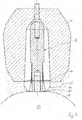
- a casting model 10 with a model surface 11 on which a forming mandrel 12 is attached is only shown schematically.
- the shaping mandrel 12 has a foot 13 and a receiving area 14 which is arranged above the foot and ends in a tip 15.
- a feeder 16 is placed on the forming mandrel 12 and has a circumferential side wall 18, a cover area 19 and a bottom surface 17.
- an inner cavity 31 is formed as a feeder volume.
- a feeder opening 20 is also arranged in the bottom surface 17, via which the liquid metal can flow into the inner cavity 31 or flow out again during the casting process.
- an elastically expandable sheath 21 in the form of a membrane made of a suitable rubber or plastic mixture is arranged on this, which is attached with its one end 22 to the foot 13 of the forming mandrel 12 in the immediate vicinity of the model surface 11 and with its the other end 23 is attached to an upper point of the receiving area 14 of the forming mandrel 12 and thereby encloses the corresponding area of the forming mandrel 12. It can be seen that an intermediate space 30 is formed between the casing 21 and the forming mandrel 12.
- the casing 21 can be brought into the space 30 by introducing a gaseous or liquid medium via an inlet and outlet line (not shown) into the in Fig. 2 shown expanded state. It can be seen here that the side area of the casing 21 is covered by a Corresponding reinforcement 24 is reinforced to the extent that under the action of the molding pressure the feeder 16 moves relative to the stationary forming mandrel 12 in the direction of the model surface 11 and thereby slides over the outer contour of the casing 21 secured with a reinforcement 24 for this purpose.
- the molding process begins after introducing a molding material 25 into the casting mold, not shown, this state is over with the filled molding material Fig. 3 evident. It can be seen that even before the start of the molding process, the expanded envelope 21 bridges the distance between the model surface 11 and into the inner cavity 31 of the feeder 16.
- Fig. 4 the position of the feeder 16 on the forming mandrel 12 after the molding pressure has been applied and the end of the molding process is shown, and it can be seen that the bottom surface 17 of the feeder 16 is still at a certain distance from the model surface 11, this distance being expanded by the Sheath 21 is still bridged. It can also be seen that due to the connection of the lower end 22 of the casing 21 to the base 13 of the forming mandrel standing on the model surface, a gusset 27 formed by the molding material 25 has set in in this area.
- the casing 21 is returned to its original shape according to FIG Fig. 1 returned by the medium introduced, for example, into the space 30 being drained off again.
- This state is in Fig. 5 shown.
- Out Fig. 5 it can be seen that the contour 26 of the molding material 25 formed by the expanded envelope during molding is maintained, which also applies to the gusset 27.
- the casting model 10 including the molding mandrel 12 has been removed from the casting mold, the cavities created thereby are filled with the liquid metal.
- the hot metal flows over the from during the casting process Molding mandrel in the path kept free in the molding material into the inner cavity 31 of the feeder 16 and back again.
- the feeder remainder 28 has a predetermined breaking point 27 a formed by the gusset 27, which is located directly on the surface of the cast part 29.
- the feeder remainder 28 can be knocked off at this predetermined breaking point 27a, the amount of cleaning that is then still required for smoothing the surface of the cast part 29 being correspondingly low.
- Fig. 6 retain the representation of the feeder, although the feeder largely loses its represented shape during the casting process.
- the forming mandrel can alternatively also be used as a so-called spring mandrel according to FIG DE 10 2010 022 834 B4 be formed, whereby there is also a displacement of the feeder 16 in the direction of the model surface 11, but without piercing the cover area of the feeder.
- the advantageous function of the shaping mandrel 12 according to the invention is also given when the shaping mandrel 12 is designed as a rigid mandrel and the force caused by the pressure exerted during the molding of the feeder is absorbed in the head of the shaping mandrel 12, so there is no displacement of the feeder 16 comes on the mandrel 12.
- the expanded envelope 21 ensures the formation of a corresponding predetermined breaking point 27a.
Landscapes
- Engineering & Computer Science (AREA)
- Mechanical Engineering (AREA)
- Moulds For Moulding Plastics Or The Like (AREA)
- Molds, Cores, And Manufacturing Methods Thereof (AREA)
Description
- Die Erfindung betrifft einen Aufformdorn zum Ansetzen an ein bei der Herstellung einer beim Gießen von Metallen verwendeten Gießform in diese eingeformtes Gießmodell, aufweisend einen auf der Modelloberfläche des Gießmodells aufstehenden Fuß und einen auf dem Fuß angeordneten Aufnahmebereich zur Aufnahme eines bei der Herstellung der Gießform darin einzuformenden Speisers, wobei der Speiser mit einer in seiner dem Gießmodell zugewandten Bodenfläche ausgebildeten Speiseröffnung vor dem Einformen auf den Aufformdorn aufgesteckt ist. Ferner betrifft die Erfindung ein einen entsprechenden Aufformdorn aufweisendes Gießmodell sowie ein Verfahren zum Gießen von Metallen unter Einsatz eines entsprechenden Gießmodells.
- In der Gießereitechnik ist es häufig notwendig, in den Gießformen zusätzliche Speiser anzuordnen, deren Speiserkorpus sich beim Abguss des Gussteiles mit dem flüssigen Metall füllt und bei der Erstarrung des Gussteiles auftretende Volumendefizite ausgleicht, um eine Lunkerbildung im Gussteil zu verhindern. Dazu müssen die Speiser so beschaffen sein, dass das darin eingespeiste flüssige Metall später als das Gussteil erstarrt, damit während des Erstarrungsvorganges ein Materialtransport zum Gussteil hin stattfinden kann, der das Gussteil dichtspeist. Hierzu bestehen die Speiser aus einem exothermen und/oder isolierenden Material. Im Rahmen von bekannten Verfahren zur Herstellung von mit Speisern versehenen Gießformen werden die Speiser mit einer beliebigen geometrischen Form an der zu speisenden Stelle des späteren Gussteils an dem Gießmodell angeordnet und bei der Erstellung der Gießform durch Verdichtung eines eingebrachten Formstoffes fest eingeformt. Zur Fixierung des Speisers beim Einformen sind sogenannte Aufformdorne bekannt, die auf der Modelloberfläche des jeweiligen Gießmodells angebracht sind. Ein derartiger Aufformdorn mit den gattungsgemäßen Merkmalen ist beispielsweise in einer Ausbildung als sogenannter Federdorn aus der
DE 10 2010 022 834 B4 bekannt, wobei in dieser Druckschrift auch der technische Hintergrund für die Anordnung von Speisern und der Einsatz von Aufformdornen beschrieben ist. Insofern werden die Ausführungen in derDE 10 2010 022 834 B4 durch Verweis mit in die Offenbarung der vorliegenden Anmeldung einbezogen. Ein Aufformdorn mit den Merkmalen des Oberbegriffs des Anspruchs 1 ist zudem ausWO 2005/051568 A1 bekannt. - Beim Einsatz von Speisern besteht generell das Problem, dass nach dem Abguss in dem Speiserkorpus jeweils erstarrtes Gussmaterial in Form eines sogenannten Speiserrestes verbleibt, der nach dem Entformen des Gussteils von diesem entfernt werden muss. Um diese Abtrennung zu erleichtern, ist die Verwendung von sogenannten Brechkernen bekannt, die auf der dem Gießmodell zugewandten Unterseite des Speiserkorpus an dem Speiserkorpus festgelegt sind, aus einem feuerfesten Material bestehen und eine Durchtrittsöffnung aufweisen, über die das aus dem von dem Gießmodell gebildeten Formhohlraum der Gießform aufsteigende heiße Metall in den inneren Hohlraum des Speiserkorpus beziehungsweise von dort aus wieder zurück in den Formhohlraum der Gießform strömt. Die in der Regel durch Schießen in einer Schießmaschine hergestellten Brechkerne sind scheibenförmig ausgebildet, wobei die Durchtrittsöffnung von einer im scheibenförmigen Brechkernkörper ausgebildeten Einschnürung gebildet ist, um dadurch eine Sollbruchstelle für das Abbrechen des Speiserrestes von der Oberfläche des Gussstückes zu schaffen. Eine derartige Anordnung des Speisers mit einem Brechkern ist beispielsweise aus der
WO 20091103539 A1 - Soweit beim Einformen des Speisers in der Gießform sich der Speiser aufgrund des ausgeübten Formdrucks in die Richtung des Gießmodells verschiebt, kommt der Speiser einschließlich eines an ihm gegebenenfalls angebrachten Brechkerns in der Regel nicht an der Modelloberfläche zur Anlage, sondern bleibt in einem mehr oder weniger großen Abstand dazu stehen. Nach Entformen des Gießmodells mit Aufformdorn wird der verbleibende Hohlraum beim Gießvorgang mit dem flüssigen Metall ausgefüllt, so dass sich die von dem Brechkern bereitgestellte Sollbruchstelle in einem entsprechenden Abstand zur Oberfläche des abgegossenen Gussteils befindet. Der dadurch bedingte, mehr oder weniger große Speiserrest muss anschließend durch aufwändige Putzarbeiten beseitigt werden.
- Der Erfindung liegt daher die Aufgabe zugrunde, einen Aufformdorn zur Fixierung eines Speisers beim Einformprozess zur Verfügung zu stellen, mittels dessen auf den Einsatz eines zusätzlichen Brechkerns oder andere, eine der Speiseröffnung zugeordnete Einschnürung ausbildender Bauteile verzichtet und dennoch ein kleinerer Speiserhals und ein damit verbundenes einfaches Abtrennen des Speiserrestes nahe der Gussteiloberfläche ermöglicht wird.
- Die Lösung dieser Aufgabe ergibt sich einschließlich vorteilhafter Ausgestaltungen und Weiterbildungen der Erfindung aus dem Inhalt der Patentansprüche, welche dieser Beschreibung nachgestellt sind.
- Die Erfindung sieht in ihrem Grundgedanken zunächst einen Aufformdorn mit den eingangs genannten Merkmalen vor, bei welchem an dem Aufformdorn eine wenigstens dessen Fuß und/oder einen Teilbereich von dessen Aufnahmebereich für den Speiser umschließende, elastisch aufweitbare und endseitig an den Fuß des Aufformdorns unmittelbar der Modelloberfläche benachbart angeschlossene Umhüllung angebracht ist derart, dass die vor Beginn des Einformens aufgeweitete Umhüllung einen nach dem Einformen des Speisers noch bestehenden Abstand zwischen Modelloberfläche und Bodenfläche des Speisers überbrückt, so dass nach dem Entformen von Gießmodell mit daran angesetztem Aufformdorn aus der Gießform eine durch die Kontur der aufgeweiteten Umhüllung ausgebildete Sollbruchstelle für einen nach Abschluss des Gießvorganges verbleibenden Speiserrest ausgebildet ist.
- Insoweit ist mit der erfindungsgemäßen Ausbildung des Aufformdorns der Vorteil verbunden, dass aufgrund der mit ihrem einen Ende unmittelbar an der Modelloberfläche anschließenden und während des Einformens aufgeweiteten Umhüllung anschließend nach dem Entformen des Gießmodells einschließlich des Aufformdorns an der Oberfläche des späteren Gussteils eine in etwa den Durchmesser des Fußes des Aufformdorns aufweisende Einschnürung als Sollbruchstelle für das spätere Abschlagen des Speiserrests unmittelbar an der Gussteiloberfläche ausgebildet wird. Somit ist ein gegebenenfalls noch erforderlicher Putzaufwand für das Entfernen des Speiserrestes vom Gussteil ganz wesentlich reduziert. Da aufgrund der Erstreckung der Umhüllung von ihrer Einspannung am Fuß des Aufformdorns mindestens bis in den Aufnahmebereich des Aufformdorns hinein ein schon vor dem Einwirken des Formdrucks bestehender Abstand zwischen dem Speiser und der Modelloberfläche überbrückt wird, kommt es auch im Falle der Verschiebung des Speisers aufgrund des Formdrucks auf das Maß der Verschiebung nicht weiter an. Unabhängig davon, in welchem Abstand sich die Bodenfläche des Speisers bei Beendigung des Formvorganges befindet, wird der dann noch bestehende Abstand zur Modelloberfläche durch die aufgeweitete Umhüllung weiterhin überbrückt, während gleichzeitig die von der Umhüllung ausgebildete Sollbruchstelle immer ortsfest an der Modelloberfläche verbleibt. Insofern ist der Einsatz eines Brechkerns zur Ausbildung einer Sollbruchstelle nicht mehr erforderlich.
- Nach einem Ausführungsbeispiel der Erfindung ist vorgesehen, dass der Zwischenraum zwischen der Umhüllung und dem Aufformdorn an eine Zuleitung für ein in den Zwischenraum einzuleitendes Medium angeschlossen ist, wobei gemäß einem weiteren Ausführungsbeispiel der Erfindung diese Zuleitung auch als Ableitung für das in den Zwischenraum eingeleitete Medium ausgebildet sein kann. Alternativ kann vorgesehen sein, dass an den Zwischenraum eine gesonderte Ableitung für das in den Zwischenraum eingeleitete Medium angeschlossen ist.
- Nach einem Ausführungsbeispiel der Erfindung ist die elastisch aufweitbare Umhüllung als eine aus einer geeigneten Gummi- oder Kunststoffmischung hergestellte Membran ausgebildet.
- Nach einem Ausführungsbeispiel der Erfindung kann vorgesehen sein, dass der Aufformdorn als starrer Dorn ausgebildet ist. In diesem Fall kann es sich so verhalten, dass es beim Aufformen nicht zu einer Verschiebung des Speisers auf dem Aufformdorn kommt und insoweit der Aufformdruck im Kopf des Speisers abgefangen wird. Alternativ kann jedoch eine gewisse Verschiebung des Speisers auf dem Aufformdorn zugelassen sein, im Rahmen derer das in einen inneren Hohlraum als Speiservolumen des Speisers hineinreichende obere Ende des Aufformdorns den der Bodenfläche gegenüberliegenden Deckelbereich des Speisers bei dessen Verschiebung auf dem Aufformdorn durchstößt.
- Alternativ kann vorgesehen sein, dass der Aufformdorn als Federdorn mit einem relativ zu seinem Fuß gegen Federkraft verschiebbaren Aufnahmebereich für den Speiser ausgebildet ist. Hierbei kann vorgesehen sein, dass der als Federdorn ausgebildete Aufformdorn mit einem in das Gießmodell einschiebbaren Fuß ausgebildet ist, wie dies aus der gattungsbildenden
DE 10 2010 022 834 B4 bekannt ist. - Gegenstand der Erfindung ist darüber hinaus die Verwendung eines erfindungsgemäß ausgestalteten Aufformdorns mit einem Gießmodell, wobei der Aufformdorn die entsprechend offenbarte elastisch aufweitbare und endseitig an dem Fuß des Aufformdorns angeschlossene Umhüllung aufweist. Ein derartiger Aufformdorn wird bei seiner Verwendung in einer an der Modelloberfläche des Gießmodells angebrachten Bohrung eingeschraubt oder sonstwie an der Modelloberfläche befestigt, so dass die am Aufformdorn befindliche aufweitbare Umhüllung beim Einformen eines Speisers dann zu Beginn des Einformprozesses in aufgeweitetem Zustand den bestehenden Abstand zwischen Gießmodell und der Bodenfläche des auf den Aufformdorn aufgesetzten Speisers überbrückt.
- Ein weiterer Gegenstand der Erfindung betrifft ein Gießmodell für die Herstellung von Gießformen, bei welchem ein entsprechend den vorstehend beschriebenen Merkmalen ausgebildeter Aufformdorn zum Einsatz gebracht ist.
- Schließlich betrifft die Erfindung ein Verfahren zum Gießen von Metallen mittels einer Gießform, wobei ein Gießmodell mit einem daran angesetzten, entsprechend den vorstehend beschriebenen Merkmalen ausgebildeten Aufformdorn bereitgestellt ist. Der Einsatz eines derartigen, eine elastisch aufweitbare Umhüllung aufweisenden Aufformdorns bedingt eine Änderung des sonst bei einem starren Aufformdorn oder einem sogenannten Federdorn üblichen Verfahrensablaufes. Im Einzelnen wird hierbei ein Speiser auf den Aufformdorn aufgesteckt, und es wird anschließend die an dem Aufformdorn befindliche Umhüllung in ihren aufgeweiteten Zustand versetzt. Anschließend wird das Gießmodell einschließlich des daran durch das Aufsetzen auf den Aufformdorn fixierten Speisers durch Einbringen eines Formstoffes in die Gießform eingeformt, anschließend wird die Umhüllung wieder in ihren ursprünglichen, nicht aufgeweiteten Zustand zurückgeführt, und nachfolgend wird das Gießmodell einschließlich Aufformdorn aus der Gießform entfernt. Der in der Gießform ausgebildete Hohlraum wird mit flüssigem Metall gefüllt, und nach Erstarren des Metalls wird der auf der Metalloberfläche des Gussteils verbleibende Speiserrest an der durch die Kontur der während des Einformens aufgeweiteten Umhüllung an der Modelloberfläche geschaffenen Sollbruchstelle abgeschlagen.
- In der Zeichnung ist ein Ausführungsbeispiel der Erfindung wiedergegeben, welches nachstehend beschrieben ist. Es zeigen:
- Fig. 1:
- einen auf einer entsprechend angedeuteten Modelloberfläche eines Gießmodells angesetzten Aufformdorn in einer geschnittenen Darstellung bei nicht aufgeweiteter Umhüllung einschließlich eines auf den Aufformdorn aufgesetzten Speisers vor Einbringen des Formstoffes,
- Fig. 2:
- den Gegenstand der
Fig. 1 mit der in einem aufgeweiteten Zustand befindlichen Umhüllung, - Fig. 3:
- den Gegenstand der
Fig. 2 bei in die Gießform eingefülltem Formstoff vor Einwirken des Formdrucks, - Fig. 4:
- den Gegenstand der
Fig. 3 nach Einwirken des Formdrucks, - Fig. 5:
- den Gegenstand der
Fig. 4 bei in den Ausgangszustand gemäßFig. 1 zurückgeführter Umhüllung vor dem Entformen des Gießmodells einschließlich des Aufformdorns, - Fig. 6:
- den nach dem Gießvorgang am Gussteil verbliebenen Speiserrest einschließlich der von der Umhüllung ausgebildeten Sollbruchstelle.
- In der
Fig. 1 ist lediglich schematisch ein Gießmodell 10 mit einer Modelloberfläche 11 dargestellt, auf der ein Aufformdorn 12 befestigt ist. Der Aufformdorn 12 hat einen Fuß 13 sowie einen oberhalb des Fußes angeordneten Aufnahmebereich 14, der in einer Spitze 15 ausläuft. Auf den Aufformdorn 12 ist ein Speiser 16 aufgesetzt, der eine umlaufende Seitenwand 18, einen Deckelbereich 19 sowie eine Bodenfläche 17 aufweist. Im Inneren des Speisers 16 ist ein innerer Hohlraum 31 als Speiservolumen ausgebildet. In der Bodenfläche 17 ist weiterhin eine Speiseröffnung 20 angeordnet, über welche beim Gießvorgang das flüssige Metall in den inneren Hohlraum 31 einströmen beziehungsweise daraus wieder abströmen kann.
Im unteren Bereich des Aufformdorns 12 ist an diesem eine elastisch aufweitbare Umhüllung 21 in Form einer aus einer geeigneten Gummi- oder Kunststoffmischung gefertigten Membran angeordnet, die mit ihrem einen Ende 22 am Fuß 13 des Aufformdorns 12 in unmittelbarer Nähe der Modelloberfläche 11 befestigt und mit ihrem anderen Ende 23 an einer oberen Stelle des Aufnahmebereichs 14 des Aufformdorns 12 befestigt ist und dabei den entsprechenden Bereich des Aufformdorns 12 umschließt. Es ist zu erkennen, dass zwischen der Umhüllung 21 und dem Aufformdorn 12 ein Zwischenraum 30 ausgebildet ist. - Wie aus
Fig. 2 ersichtlich ist, kann die Umhüllung 21 durch Einbringen eines gasförmigen oder flüssigen Mediums in den Zwischenraum 30 über eine nicht dargestellte Zu- und Ableitung in den inFig. 2 dargestellten aufgeweiteten Zustand verbracht werden. Hierbei ist erkennbar, dass der Seitenbereich der Umhüllung 21 durch eine entsprechende Verstärkung 24 verstärkt ist, soweit unter Einwirkung des Formdrucks der Speiser 16 sich relativ zum feststehenden Aufformdorn 12 in Richtung zur Modelloberfläche 11 verschiebt und dabei über die Außenkontur der hierzu mit einer Verstärkung 24 abgesicherten Umhüllung 21 gleitet. - Soweit ausgehend von der in
Fig. 2 dargestellten Stellung der Einformvorgang nach Einbringen eines Formstoffes 25 in die nicht weiter dargestellte Gießform beginnt, ist dieser Zustand mit dem eingefüllten Formstoff ausFig. 3 ersichtlich. Dabei ist erkennbar, dass bereits vor Beginn des Einformvorganges die aufgeweitete Umhüllung 21 den Abstand zwischen der Modelloberfläche 11 bis in den inneren Hohlraum 31 des Speisers 16 hinein überbrückt. - In
Fig. 4 ist die Stellung des Speisers 16 auf dem Aufformdorn 12 nach dem Einwirken des Formdrucks und Beendigung des Einformvorganges gezeigt, und es ist erkennbar, dass die Bodenfläche 17 des Speisers 16 immer noch in einem gewissen Abstand zur Modelloberfläche 11 steht, wobei dieser Abstand durch die aufgeweitete Umhüllung 21 weiterhin überbrückt wird. Es ist ferner erkennbar, dass sich aufgrund der Anbindung des unteren Endes 22 der Umhüllung 21 am auf der Modelloberfläche aufstehenden Fuß 13 des Aufformdorns in diesem Bereich ein vom Formstoff 25 ausgebildeter Zwickel 27 eingestellt hat. - Im Anschluss an die Beendigung des Einformens wird die Umhüllung 21 wieder in ihre ursprüngliche Form gemäß
Fig. 1 zurückgeführt, indem das beispielsweise in den Zwischenraum 30 eingebrachte Medium wieder abgelassen wird. Dieser Zustand ist inFig. 5 dargestellt. AusFig. 5 ist zu entnehmen, dass die von der aufgeweiteten Umhüllung beim Einformen ausgebildete Kontur 26 des Formstoffes 25 aufrechterhalten bleibt, was auch für den Zwickel 27 gilt. Es ist ohne weiteres einsehbar, dass nach dem Entformen des Gießmodells 10 einschließlich Aufformdorn 12 aus der Gießform die dadurch geschaffenen Hohlräume mit dem flüssigen Metall gefüllt werden. Somit strömt das heiße Metall während des Gießvorganges über den vom Aufformdorn in den Formstoff freigehaltenen Weg in den inneren Hohlraum 31 des Speisers 16 und wieder zurück. - Nach Beendigung des Gießvorganges kommt es zu einer Erstarrung des Metalls, und das in den entsprechenden Fließwegen beziehungsweise Hohlräumen noch außerhalb des in dem durch das Entformen des Gießmodells 10 hergestellten Formhohlraum gegossenen Gussteils 29 anstehende Metall bildet einen Speiserrest 28 aus. Wie aus
Fig. 6 erkennbar, weist der Speiserrest 28 eine von dem Zwickel 27 gebildete Sollbruchstelle 27a auf, die unmittelbar an der Oberfläche des Gussteils 29 liegt. An dieser Sollbruchstelle 27a kann der Speiserrest 28 abgeschlagen werden, wobei ein dann noch erforderlicher Putzaufwand zum Glätten der Oberfläche des Gussteils 29 entsprechend gering ist. Der Einfachheit halber ist inFig. 6 die Darstellung des Speisers beibehalten, obwohl der Speiser während des Gießprozesses seine dargestellte Gestalt weitgehend verliert. - Wie nicht weiter dargestellt, kann alternativ der Aufformdorn auch als sogenannter Federdorn entsprechend der
DE 10 2010 022 834 B4 ausgebildet sein, wobei es ebenfalls zu einer Verlagerung des Speisers 16 in Richtung zur Modelloberfläche 11 hinkommt, allerdings ohne ein Durchstoßen des Deckelbereichs des Speisers. Schließlich ist die vorteilhafte Funktion des erfindungsgemäßen Aufformdorns 12 auch dann gegeben, wenn der Aufformdorn 12 als starrer Dorn ausgebildet ist und die durch den beim Einformen des Speisers einwirkenden Formdruck bewirkte Kraft im Kopf des Aufformdorns 12 abgefangen wird und es insoweit nicht zu einer Verschiebung des Speisers 16 auf dem Aufformdorn 12 kommt. Auch in diesem Fall sorgt die aufgeweitete Umhüllung 21 für die Ausbildung einer entsprechenden Sollbruchstelle 27a.
Claims (10)
- Aufformdorn (12) zum Ansetzen an ein bei der Herstellung einer beim Gießen von Metallen verwendeten Gießform in diese eingeformtes Gießmodell (10), aufweisend einen auf der Modelloberfläche (11) des Gießmodells (10) aufstehenden Fuß (13) und einen auf dem Fuß 13) angeordneten Aufnahmebereich (14) zur Aufnahme eines bei der Herstellung der Gießform darin einzuformenden Speisers (16), wobei der Speiser (16) mit einer in seiner dem Gießmodell (10) zugewandten Bodenfläche (17) ausgebildeten Speiseröffnung (20) vor dem Einformen auf den Aufformdorn (12) aufgesteckt ist, dadurch gekennzeichnet, dass an dem Aufformdorn (12) eine wenigstens dessen Fuß (13) und/oder einen Teilbereich von dessen Aufnahmebereich (14) für den Speiser (16) umschließende, elastisch aufweitbare und endseitig an dem Fuß (13) des Aufformdorns (12) unmittelbar der Modelloberfläche (11) benachbart angeschlossene Umhüllung (21) angebracht ist derart, dass die vor Beginn des Einformens aufgeweitete Umhüllung (21) einen nach dem Einformen des Speisers (16) noch bestehenden Abstand zur Modelloberfläche (11) überbrückt, so dass nach dem Entformen von Gießmodell (10) mit daran angesetztem Aufformdorn (12) aus der Gießform eine durch die Kontur (26) der aufgeweiteten Umhüllung (21) ausgebildete Sollbruchstelle (27a) für einen nach Abschluss des Gießvorganges verbleibenden metallischen Speiserrest (28) ausgebildet ist, wobei ein Zwischenraum (30) zwischen der Umhüllung (21) und dem Aufformdorn (12) an eine Zuleitung für ein in den Zwischenraum (30) einzuleitendes Medium angeschlossen ist.
- Aufformdorn (12) nach Anspruch 1, bei welchem die Zuleitung auch als Ableitung für das in den Zwischenraum (30) eingeleitete Medium ausgebildet ist.
- Aufformdorn (12) nach Anspruch 1, bei welchem der Zwischenraum (30) an eine gesonderte Ableitung für das in den Zwischenraum (30) eingeleitete Medium angeschlossen ist.
- Aufformdorn (12) nach einem der Ansprüche 1 bis 3, bei welchem die Umhüllung (21) als eine aus einer geeigneten Gummi- oder Kunststoffmischung hergestellte Membran ausgebildet ist.
- Aufformdorn (12) nach einem der Ansprüche 1 bis 4, bei welchem der Aufformdorn (12) als starrer Dorn ausgebildet ist.
- Aufformdorn (12) nach einem der Ansprüche 1 bis 4, bei welchem der Aufformdorn (12) als Federdorn mit einem relativ zu seinem Fuß (13) gegen Federkraft verschiebbaren Aufnahmebereich (14) für den Speiser (16) ausgebildet ist.
- Aufformdorn (12) nach einem der Ansprüche 1 bis 4, bei welchem der Aufformdorn (12) als Federdorn mit einem gegen Federkraft in das Gießmodell (10) einschiebbaren Fuß ausgebildet ist.
- Verwendung eines gemäß einem der Ansprüche 1 bis 7 ausgebildeten Aufformdorns (12) mit einem Gießmodell (10) für die Herstellung von beim Gießen von Metallen verwendeten Gießformen, wobei der Aufformdorn (12) an der Modelloberfläche (11) des Gießmodells (10) angesetzt ist.
- Gießmodell (10) für die Herstellung von beim Gießen von Metallen verwendeten Gießformen mit einem an der Modelloberfläche (11) des Gießmodells (10) angesetzten Aufformdorn (12) gemäß einem der Ansprüche 1 bis 7.
- Verfahren zum Gießen von Metallen mittels einer Gießform, wobei ein Gießmodell (10) mit einem daran angesetzten, gemäß einem der Ansprüche 1 bis 7 ausgebildeten Aufformdorn (12) bereitgestellt wird, bei welchem ein Speiser (16) auf den Aufformdorn (12) aufgesteckt wird; anschließend die an dem Aufformdorn (12) befindliche Umhüllung (21) aufgeweitet wird; anschließend das Gießmodell (10) einschließlich des daran fixierten Speisers (16) durch Einbringen eines Formstoffes (25) in der Gießform eingeformt wird; die Umhüllung wieder in ihren ursprünglichen, nicht aufgeweiteten Zustand zurückgeführt wird; anschließend das Gießmodell (10) einschließlich Aufformdorn (12) aus der Gießform entfernt wird; der bestehende Hohlraum in der Gießform mit dem flüssigen Metall gefüllt wird; nach Erstarren des Metalls der auf der Oberfläche des Gussteils (29) verbleibende metallische Speiserrest (28) an der durch die Kontur (26) der während des Einformens aufgeweiteten Umhüllung (21) an der Modelloberfläche (11) geschaffenen Sollbruchstelle (27a) abgeschlagen wird.
Applications Claiming Priority (2)
| Application Number | Priority Date | Filing Date | Title |
|---|---|---|---|
| DE102015118335 | 2015-10-27 | ||
| PCT/EP2016/075091 WO2017072004A1 (de) | 2015-10-27 | 2016-10-19 | Aufformdorn mit einer aufweitbaren umhüllung und giessmodell mit aufformdorn sowie verfahren zum giessen von metallen |
Publications (2)
| Publication Number | Publication Date |
|---|---|
| EP3368234A1 EP3368234A1 (de) | 2018-09-05 |
| EP3368234B1 true EP3368234B1 (de) | 2020-08-26 |
Family
ID=57144996
Family Applications (1)
| Application Number | Title | Priority Date | Filing Date |
|---|---|---|---|
| EP16782282.4A Active EP3368234B1 (de) | 2015-10-27 | 2016-10-19 | Aufformdorn mit einer aufweitbaren umhüllung und giessmodell mit aufformdorn sowie verfahren zum giessen von metallen |
Country Status (2)
| Country | Link |
|---|---|
| EP (1) | EP3368234B1 (de) |
| WO (1) | WO2017072004A1 (de) |
Families Citing this family (1)
| Publication number | Priority date | Publication date | Assignee | Title |
|---|---|---|---|---|
| DE102019102449B4 (de) | 2019-01-31 | 2026-05-13 | Chemex Foundry Solutions Gmbh | Einteiliger Speiserkörper zur Verwendung beim Gießen von Metallen |
Family Cites Families (3)
| Publication number | Priority date | Publication date | Assignee | Title |
|---|---|---|---|---|
| GB0325134D0 (en) * | 2003-10-28 | 2003-12-03 | Foseco Int | Improved feeder element for metal casting |
| DE102008009730A1 (de) | 2008-02-19 | 2009-08-20 | AS Lüngen GmbH | Speiser mit eingestecktem Brechkern |
| DE102010022834B4 (de) | 2010-06-07 | 2012-05-31 | Ask Chemicals Feeding Systems Gmbh | Federdorn und Gießmodell mit Federdorn |
-
2016
- 2016-10-19 EP EP16782282.4A patent/EP3368234B1/de active Active
- 2016-10-19 WO PCT/EP2016/075091 patent/WO2017072004A1/de not_active Ceased
Non-Patent Citations (1)
| Title |
|---|
| None * |
Also Published As
| Publication number | Publication date |
|---|---|
| WO2017072004A1 (de) | 2017-05-04 |
| EP3368234A1 (de) | 2018-09-05 |
Similar Documents
| Publication | Publication Date | Title |
|---|---|---|
| EP1184104B1 (de) | Speisereinsatz | |
| EP2097193B1 (de) | Speisereinsatz und speiserelement | |
| EP1345716B1 (de) | Speiser mit einem rohrähnlichen körper | |
| DE602004000859T2 (de) | Verbessertes zuführelement und system für metallguss | |
| EP3003601B1 (de) | Speisereinsatz, formelement für den speisereinsatz und verfahren zum giessen von metall unter verwendung derselben | |
| DE602006000751T2 (de) | Vollformgussvorrichtung und Verfahren zur Herstellung eines hohlen Einlaufssystems | |
| DE102015101913B3 (de) | Eingussspeiser mit integriertem losen Filter, Gusssystem bestehend aus dem Eingussspeiser und einem Formmodell und Verfahren zur Herstellung einer Gussform | |
| DE102005008324A1 (de) | Speiser mit beweglicher Tülle | |
| EP1732719B1 (de) | Speiser mit verformbarer tülle | |
| DE202013001933U1 (de) | Speisereinsatz | |
| EP3349923B1 (de) | Verfahren zur herstellung eines speisers in einer kernschiessmaschine und zur durchfuehrung des verfahrens geeigneter kernkasten | |
| EP3727723A1 (de) | Verfahren zum herstellen eines formteils sowie speisereinsatz zur verwendung in einem solchen verfahren | |
| EP2956256B1 (de) | Speisereinsatz und verfahren zu dessen anordnung in einer giessform | |
| DE102005019385A1 (de) | Filterspeiser und Verfahren zur Herstellung einer Giessform | |
| EP3368234A1 (de) | Aufformdorn mit einer aufweitbaren umhüllung und giessmodell mit aufformdorn sowie verfahren zum giessen von metallen | |
| DE10142357B4 (de) | Speiser mit einem rohrähnlichen Körper | |
| EP2818262A1 (de) | Speisereinsatz mit isoliertem Speiserfuß | |
| DE102005025701B4 (de) | Speiser mit nachgiebigem Speiserunterteil | |
| DE10059481B4 (de) | Speiser mit einem rohrähnlichen Körper | |
| DE102010022834B4 (de) | Federdorn und Gießmodell mit Federdorn | |
| EP2532500B1 (de) | Verfahren und Vorrichtung zur Herstellung von Keramikartikeln | |
| DE102014207791A1 (de) | Verfahren zum Feingießen von metallischen Bauteilen | |
| DE102013111719B4 (de) | Werkzeug und Verfahren zur Trennung eines Überlaufbutzens | |
| DE20122062U1 (de) | Speisereinsatz | |
| DE102013105769A1 (de) | Vorrichtung und Verfahren zum Druckgießen eines Kurbelgehäuses |
Legal Events
| Date | Code | Title | Description |
|---|---|---|---|
| STAA | Information on the status of an ep patent application or granted ep patent |
Free format text: STATUS: THE INTERNATIONAL PUBLICATION HAS BEEN MADE |
|
| PUAI | Public reference made under article 153(3) epc to a published international application that has entered the european phase |
Free format text: ORIGINAL CODE: 0009012 |
|
| STAA | Information on the status of an ep patent application or granted ep patent |
Free format text: STATUS: REQUEST FOR EXAMINATION WAS MADE |
|
| 17P | Request for examination filed |
Effective date: 20180328 |
|
| AK | Designated contracting states |
Kind code of ref document: A1 Designated state(s): AL AT BE BG CH CY CZ DE DK EE ES FI FR GB GR HR HU IE IS IT LI LT LU LV MC MK MT NL NO PL PT RO RS SE SI SK SM TR |
|
| AX | Request for extension of the european patent |
Extension state: BA ME |
|
| DAV | Request for validation of the european patent (deleted) | ||
| DAX | Request for extension of the european patent (deleted) | ||
| GRAP | Despatch of communication of intention to grant a patent |
Free format text: ORIGINAL CODE: EPIDOSNIGR1 |
|
| STAA | Information on the status of an ep patent application or granted ep patent |
Free format text: STATUS: GRANT OF PATENT IS INTENDED |
|
| INTG | Intention to grant announced |
Effective date: 20200408 |
|
| GRAS | Grant fee paid |
Free format text: ORIGINAL CODE: EPIDOSNIGR3 |
|
| GRAA | (expected) grant |
Free format text: ORIGINAL CODE: 0009210 |
|
| STAA | Information on the status of an ep patent application or granted ep patent |
Free format text: STATUS: THE PATENT HAS BEEN GRANTED |
|
| AK | Designated contracting states |
Kind code of ref document: B1 Designated state(s): AL AT BE BG CH CY CZ DE DK EE ES FI FR GB GR HR HU IE IS IT LI LT LU LV MC MK MT NL NO PL PT RO RS SE SI SK SM TR |
|
| REG | Reference to a national code |
Ref country code: GB Ref legal event code: FG4D Free format text: NOT ENGLISH |
|
| REG | Reference to a national code |
Ref country code: CH Ref legal event code: EP |
|
| REG | Reference to a national code |
Ref country code: DE Ref legal event code: R096 Ref document number: 502016010968 Country of ref document: DE |
|
| REG | Reference to a national code |
Ref country code: AT Ref legal event code: REF Ref document number: 1305887 Country of ref document: AT Kind code of ref document: T Effective date: 20200915 |
|
| REG | Reference to a national code |
Ref country code: IE Ref legal event code: FG4D Free format text: LANGUAGE OF EP DOCUMENT: GERMAN |
|
| REG | Reference to a national code |
Ref country code: LT Ref legal event code: MG4D |
|
| PG25 | Lapsed in a contracting state [announced via postgrant information from national office to epo] |
Ref country code: HR Free format text: LAPSE BECAUSE OF FAILURE TO SUBMIT A TRANSLATION OF THE DESCRIPTION OR TO PAY THE FEE WITHIN THE PRESCRIBED TIME-LIMIT Effective date: 20200826 Ref country code: SE Free format text: LAPSE BECAUSE OF FAILURE TO SUBMIT A TRANSLATION OF THE DESCRIPTION OR TO PAY THE FEE WITHIN THE PRESCRIBED TIME-LIMIT Effective date: 20200826 Ref country code: BG Free format text: LAPSE BECAUSE OF FAILURE TO SUBMIT A TRANSLATION OF THE DESCRIPTION OR TO PAY THE FEE WITHIN THE PRESCRIBED TIME-LIMIT Effective date: 20201126 Ref country code: PT Free format text: LAPSE BECAUSE OF FAILURE TO SUBMIT A TRANSLATION OF THE DESCRIPTION OR TO PAY THE FEE WITHIN THE PRESCRIBED TIME-LIMIT Effective date: 20201228 Ref country code: LT Free format text: LAPSE BECAUSE OF FAILURE TO SUBMIT A TRANSLATION OF THE DESCRIPTION OR TO PAY THE FEE WITHIN THE PRESCRIBED TIME-LIMIT Effective date: 20200826 Ref country code: FI Free format text: LAPSE BECAUSE OF FAILURE TO SUBMIT A TRANSLATION OF THE DESCRIPTION OR TO PAY THE FEE WITHIN THE PRESCRIBED TIME-LIMIT Effective date: 20200826 Ref country code: NO Free format text: LAPSE BECAUSE OF FAILURE TO SUBMIT A TRANSLATION OF THE DESCRIPTION OR TO PAY THE FEE WITHIN THE PRESCRIBED TIME-LIMIT Effective date: 20201126 Ref country code: GR Free format text: LAPSE BECAUSE OF FAILURE TO SUBMIT A TRANSLATION OF THE DESCRIPTION OR TO PAY THE FEE WITHIN THE PRESCRIBED TIME-LIMIT Effective date: 20201127 |
|
| REG | Reference to a national code |
Ref country code: NL Ref legal event code: MP Effective date: 20200826 |
|
| PG25 | Lapsed in a contracting state [announced via postgrant information from national office to epo] |
Ref country code: LV Free format text: LAPSE BECAUSE OF FAILURE TO SUBMIT A TRANSLATION OF THE DESCRIPTION OR TO PAY THE FEE WITHIN THE PRESCRIBED TIME-LIMIT Effective date: 20200826 Ref country code: RS Free format text: LAPSE BECAUSE OF FAILURE TO SUBMIT A TRANSLATION OF THE DESCRIPTION OR TO PAY THE FEE WITHIN THE PRESCRIBED TIME-LIMIT Effective date: 20200826 Ref country code: NL Free format text: LAPSE BECAUSE OF FAILURE TO SUBMIT A TRANSLATION OF THE DESCRIPTION OR TO PAY THE FEE WITHIN THE PRESCRIBED TIME-LIMIT Effective date: 20200826 Ref country code: PL Free format text: LAPSE BECAUSE OF FAILURE TO SUBMIT A TRANSLATION OF THE DESCRIPTION OR TO PAY THE FEE WITHIN THE PRESCRIBED TIME-LIMIT Effective date: 20200826 Ref country code: IS Free format text: LAPSE BECAUSE OF FAILURE TO SUBMIT A TRANSLATION OF THE DESCRIPTION OR TO PAY THE FEE WITHIN THE PRESCRIBED TIME-LIMIT Effective date: 20201226 |
|
| PG25 | Lapsed in a contracting state [announced via postgrant information from national office to epo] |
Ref country code: EE Free format text: LAPSE BECAUSE OF FAILURE TO SUBMIT A TRANSLATION OF THE DESCRIPTION OR TO PAY THE FEE WITHIN THE PRESCRIBED TIME-LIMIT Effective date: 20200826 Ref country code: SM Free format text: LAPSE BECAUSE OF FAILURE TO SUBMIT A TRANSLATION OF THE DESCRIPTION OR TO PAY THE FEE WITHIN THE PRESCRIBED TIME-LIMIT Effective date: 20200826 Ref country code: RO Free format text: LAPSE BECAUSE OF FAILURE TO SUBMIT A TRANSLATION OF THE DESCRIPTION OR TO PAY THE FEE WITHIN THE PRESCRIBED TIME-LIMIT Effective date: 20200826 Ref country code: CZ Free format text: LAPSE BECAUSE OF FAILURE TO SUBMIT A TRANSLATION OF THE DESCRIPTION OR TO PAY THE FEE WITHIN THE PRESCRIBED TIME-LIMIT Effective date: 20200826 Ref country code: DK Free format text: LAPSE BECAUSE OF FAILURE TO SUBMIT A TRANSLATION OF THE DESCRIPTION OR TO PAY THE FEE WITHIN THE PRESCRIBED TIME-LIMIT Effective date: 20200826 |
|
| REG | Reference to a national code |
Ref country code: DE Ref legal event code: R097 Ref document number: 502016010968 Country of ref document: DE |
|
| PG25 | Lapsed in a contracting state [announced via postgrant information from national office to epo] |
Ref country code: ES Free format text: LAPSE BECAUSE OF FAILURE TO SUBMIT A TRANSLATION OF THE DESCRIPTION OR TO PAY THE FEE WITHIN THE PRESCRIBED TIME-LIMIT Effective date: 20200826 Ref country code: AL Free format text: LAPSE BECAUSE OF FAILURE TO SUBMIT A TRANSLATION OF THE DESCRIPTION OR TO PAY THE FEE WITHIN THE PRESCRIBED TIME-LIMIT Effective date: 20200826 |
|
| REG | Reference to a national code |
Ref country code: CH Ref legal event code: PL |
|
| PG25 | Lapsed in a contracting state [announced via postgrant information from national office to epo] |
Ref country code: LU Free format text: LAPSE BECAUSE OF NON-PAYMENT OF DUE FEES Effective date: 20201019 Ref country code: MC Free format text: LAPSE BECAUSE OF FAILURE TO SUBMIT A TRANSLATION OF THE DESCRIPTION OR TO PAY THE FEE WITHIN THE PRESCRIBED TIME-LIMIT Effective date: 20200826 Ref country code: SK Free format text: LAPSE BECAUSE OF FAILURE TO SUBMIT A TRANSLATION OF THE DESCRIPTION OR TO PAY THE FEE WITHIN THE PRESCRIBED TIME-LIMIT Effective date: 20200826 |
|
| PLBE | No opposition filed within time limit |
Free format text: ORIGINAL CODE: 0009261 |
|
| STAA | Information on the status of an ep patent application or granted ep patent |
Free format text: STATUS: NO OPPOSITION FILED WITHIN TIME LIMIT |
|
| REG | Reference to a national code |
Ref country code: BE Ref legal event code: MM Effective date: 20201031 |
|
| GBPC | Gb: european patent ceased through non-payment of renewal fee |
Effective date: 20201126 |
|
| PG25 | Lapsed in a contracting state [announced via postgrant information from national office to epo] |
Ref country code: IT Free format text: LAPSE BECAUSE OF FAILURE TO SUBMIT A TRANSLATION OF THE DESCRIPTION OR TO PAY THE FEE WITHIN THE PRESCRIBED TIME-LIMIT Effective date: 20200826 Ref country code: FR Free format text: LAPSE BECAUSE OF NON-PAYMENT OF DUE FEES Effective date: 20201026 |
|
| 26N | No opposition filed |
Effective date: 20210527 |
|
| PG25 | Lapsed in a contracting state [announced via postgrant information from national office to epo] |
Ref country code: CH Free format text: LAPSE BECAUSE OF NON-PAYMENT OF DUE FEES Effective date: 20201031 Ref country code: BE Free format text: LAPSE BECAUSE OF NON-PAYMENT OF DUE FEES Effective date: 20201031 Ref country code: SI Free format text: LAPSE BECAUSE OF FAILURE TO SUBMIT A TRANSLATION OF THE DESCRIPTION OR TO PAY THE FEE WITHIN THE PRESCRIBED TIME-LIMIT Effective date: 20200826 Ref country code: LI Free format text: LAPSE BECAUSE OF NON-PAYMENT OF DUE FEES Effective date: 20201031 |
|
| PG25 | Lapsed in a contracting state [announced via postgrant information from national office to epo] |
Ref country code: IE Free format text: LAPSE BECAUSE OF NON-PAYMENT OF DUE FEES Effective date: 20201019 |
|
| PG25 | Lapsed in a contracting state [announced via postgrant information from national office to epo] |
Ref country code: GB Free format text: LAPSE BECAUSE OF NON-PAYMENT OF DUE FEES Effective date: 20201126 |
|
| PGFP | Annual fee paid to national office [announced via postgrant information from national office to epo] |
Ref country code: DE Payment date: 20210917 Year of fee payment: 6 Ref country code: TR Payment date: 20211018 Year of fee payment: 6 |
|
| PG25 | Lapsed in a contracting state [announced via postgrant information from national office to epo] |
Ref country code: IS Free format text: LAPSE BECAUSE OF FAILURE TO SUBMIT A TRANSLATION OF THE DESCRIPTION OR TO PAY THE FEE WITHIN THE PRESCRIBED TIME-LIMIT Effective date: 20201226 Ref country code: MT Free format text: LAPSE BECAUSE OF FAILURE TO SUBMIT A TRANSLATION OF THE DESCRIPTION OR TO PAY THE FEE WITHIN THE PRESCRIBED TIME-LIMIT Effective date: 20200826 Ref country code: CY Free format text: LAPSE BECAUSE OF FAILURE TO SUBMIT A TRANSLATION OF THE DESCRIPTION OR TO PAY THE FEE WITHIN THE PRESCRIBED TIME-LIMIT Effective date: 20200826 |
|
| PG25 | Lapsed in a contracting state [announced via postgrant information from national office to epo] |
Ref country code: MK Free format text: LAPSE BECAUSE OF FAILURE TO SUBMIT A TRANSLATION OF THE DESCRIPTION OR TO PAY THE FEE WITHIN THE PRESCRIBED TIME-LIMIT Effective date: 20200826 |
|
| REG | Reference to a national code |
Ref country code: AT Ref legal event code: MM01 Ref document number: 1305887 Country of ref document: AT Kind code of ref document: T Effective date: 20211019 |
|
| PG25 | Lapsed in a contracting state [announced via postgrant information from national office to epo] |
Ref country code: AT Free format text: LAPSE BECAUSE OF NON-PAYMENT OF DUE FEES Effective date: 20211019 |
|
| REG | Reference to a national code |
Ref country code: DE Ref legal event code: R119 Ref document number: 502016010968 Country of ref document: DE |
|
| PG25 | Lapsed in a contracting state [announced via postgrant information from national office to epo] |
Ref country code: DE Free format text: LAPSE BECAUSE OF NON-PAYMENT OF DUE FEES Effective date: 20230503 |
|
| PG25 | Lapsed in a contracting state [announced via postgrant information from national office to epo] |
Ref country code: TR Free format text: LAPSE BECAUSE OF NON-PAYMENT OF DUE FEES Effective date: 20221019 |