EP3368197B1 - Method for manufacturing of a carbon nanomembrane - Google Patents
Method for manufacturing of a carbon nanomembrane Download PDFInfo
- Publication number
- EP3368197B1 EP3368197B1 EP16788107.7A EP16788107A EP3368197B1 EP 3368197 B1 EP3368197 B1 EP 3368197B1 EP 16788107 A EP16788107 A EP 16788107A EP 3368197 B1 EP3368197 B1 EP 3368197B1
- Authority
- EP
- European Patent Office
- Prior art keywords
- substrate
- polymer
- layer
- carbon
- aluminised
- Prior art date
- Legal status (The legal status is an assumption and is not a legal conclusion. Google has not performed a legal analysis and makes no representation as to the accuracy of the status listed.)
- Active
Links
Images


Classifications
-
- B—PERFORMING OPERATIONS; TRANSPORTING
- B01—PHYSICAL OR CHEMICAL PROCESSES OR APPARATUS IN GENERAL
- B01D—SEPARATION
- B01D69/00—Semi-permeable membranes for separation processes or apparatus characterised by their form, structure or properties; Manufacturing processes specially adapted therefor
- B01D69/12—Composite membranes; Ultra-thin membranes
- B01D69/122—Separate manufacturing of ultra-thin membranes
-
- B—PERFORMING OPERATIONS; TRANSPORTING
- B01—PHYSICAL OR CHEMICAL PROCESSES OR APPARATUS IN GENERAL
- B01D—SEPARATION
- B01D67/00—Processes specially adapted for manufacturing semi-permeable membranes for separation processes or apparatus
- B01D67/0002—Organic membrane manufacture
- B01D67/0006—Organic membrane manufacture by chemical reactions
-
- B—PERFORMING OPERATIONS; TRANSPORTING
- B01—PHYSICAL OR CHEMICAL PROCESSES OR APPARATUS IN GENERAL
- B01D—SEPARATION
- B01D67/00—Processes specially adapted for manufacturing semi-permeable membranes for separation processes or apparatus
- B01D67/0081—After-treatment of organic or inorganic membranes
- B01D67/0088—Physical treatment with compounds, e.g. swelling, coating or impregnation
-
- B—PERFORMING OPERATIONS; TRANSPORTING
- B01—PHYSICAL OR CHEMICAL PROCESSES OR APPARATUS IN GENERAL
- B01D—SEPARATION
- B01D69/00—Semi-permeable membranes for separation processes or apparatus characterised by their form, structure or properties; Manufacturing processes specially adapted therefor
- B01D69/10—Supported membranes; Membrane supports
-
- B—PERFORMING OPERATIONS; TRANSPORTING
- B01—PHYSICAL OR CHEMICAL PROCESSES OR APPARATUS IN GENERAL
- B01D—SEPARATION
- B01D71/00—Semi-permeable membranes for separation processes or apparatus characterised by the material; Manufacturing processes specially adapted therefor
- B01D71/02—Inorganic material
- B01D71/021—Carbon
-
- B—PERFORMING OPERATIONS; TRANSPORTING
- B05—SPRAYING OR ATOMISING IN GENERAL; APPLYING FLUENT MATERIALS TO SURFACES, IN GENERAL
- B05D—PROCESSES FOR APPLYING FLUENT MATERIALS TO SURFACES, IN GENERAL
- B05D1/00—Processes for applying liquids or other fluent materials
- B05D1/18—Processes for applying liquids or other fluent materials performed by dipping
- B05D1/185—Processes for applying liquids or other fluent materials performed by dipping applying monomolecular layers
-
- B—PERFORMING OPERATIONS; TRANSPORTING
- B82—NANOTECHNOLOGY
- B82Y—SPECIFIC USES OR APPLICATIONS OF NANOSTRUCTURES; MEASUREMENT OR ANALYSIS OF NANOSTRUCTURES; MANUFACTURE OR TREATMENT OF NANOSTRUCTURES
- B82Y40/00—Manufacture or treatment of nanostructures
-
- B—PERFORMING OPERATIONS; TRANSPORTING
- B01—PHYSICAL OR CHEMICAL PROCESSES OR APPARATUS IN GENERAL
- B01D—SEPARATION
- B01D2323/00—Details relating to membrane preparation
- B01D2323/30—Cross-linking
-
- B—PERFORMING OPERATIONS; TRANSPORTING
- B01—PHYSICAL OR CHEMICAL PROCESSES OR APPARATUS IN GENERAL
- B01D—SEPARATION
- B01D2323/00—Details relating to membrane preparation
- B01D2323/34—Use of radiation
-
- B—PERFORMING OPERATIONS; TRANSPORTING
- B01—PHYSICAL OR CHEMICAL PROCESSES OR APPARATUS IN GENERAL
- B01D—SEPARATION
- B01D2323/00—Details relating to membrane preparation
- B01D2323/39—Electrospinning
-
- B—PERFORMING OPERATIONS; TRANSPORTING
- B05—SPRAYING OR ATOMISING IN GENERAL; APPLYING FLUENT MATERIALS TO SURFACES, IN GENERAL
- B05D—PROCESSES FOR APPLYING FLUENT MATERIALS TO SURFACES, IN GENERAL
- B05D2201/00—Polymeric substrate or laminate
-
- B—PERFORMING OPERATIONS; TRANSPORTING
- B05—SPRAYING OR ATOMISING IN GENERAL; APPLYING FLUENT MATERIALS TO SURFACES, IN GENERAL
- B05D—PROCESSES FOR APPLYING FLUENT MATERIALS TO SURFACES, IN GENERAL
- B05D2350/00—Pretreatment of the substrate
- B05D2350/60—Adding a layer before coating
- B05D2350/65—Adding a layer before coating metal layer
Definitions
- the invention relates to fabrication of carbon nanomembranes, which are usable for gas separation and ultrafiltration.
- CCMs carbon nanomembranes
- SAM self-assembled monolayer
- crosslinking of the individual molecules in the self-assembled monolayer by irradiation to produce a carbon nanomembrane and separation of the formed carbon nanomembrane from the original substrate.
- the substrates usually used for the initial formation of the self-assembled monolayer are (mostly atomically flat) special substrates, e.g. gold or silver layers on cleaved mica samples, gold or silver layers on silicon wafers, silicon nitride layers on silicon wafers, or flat copper foils. Common to these substrates are their stiffness (the substrates are not usable for a potential roll-to-roll production), their high price and their limited commercial availability.
- the substrates of the prior art also need pre-treatment, which could involve, amongst other steps, cleaning from organic adsorbates using, for example, Piranha solution (sulphuric acid and hydrogen peroxide - as for example described by Beyer [ A. Beyer et al. J. Vac. Sci. Technol. B 28, C6D5 (2010 )), plasma treatment and/or UV/ozone treatment.
- Piranha solution sulphuric acid and hydrogen peroxide - as for example described by Beyer [ A. Beyer et al. J. Vac. Sci. Technol. B 28, C6D5 (2010 )
- plasma treatment and/or UV/ozone treatment.
- UV/ozone treatment In the case of the silicon nitride substrate, it is necessary to carry out full oxidation of the uppermost surface layers by using, for example, UV/ozone treatment.
- the surface chemistry for the formation of a self-assembled monolayer in a solution is usually very sensitive and requires special pre-treatment of the solvents, cleaning of the reaction vessels and reaction under an inert atmosphere or in a vacuum.
- the pre-treatment of the solvents involves degassing and drying to ensure lowest levels of dissolved gases, such as oxygen.
- the cleaning of the reaction vessels includes cleaning from the adsorbates by Piranha solution.
- the reaction under inert atmosphere or vacuum is to ensure lowest levels of oxygen.
- the prior art preparation method also requires separation of the carbon nanomembrane from the original (sacrificial) substrate and includes typically etching of the substrate involving often, at least for mica and silicon-based substrates, concentrated hydrofluoric acid, which is a highly corrosive and an acute contact poison.
- Such processes involving hydrofluoric acids have to be handled with extreme care, using protective equipment, hoods and safety precautions beyond those used for processes involving other mineral acids.
- a universal scheme to convert aromatic molecular monolayers into functional carbon nanomembranes is known from the publication of the same name in ACS Nano, Vol. 7, No 8, 6489-6497 which describes carbon nanomembranes produced from self-assembled monolayers of 1,1'-biphenyl-4-thiol (BPT) and other aromatic sulphur-containing mole-cules on gold substrates.
- BPT 1,1'-biphenyl-4-thiol
- other detailed descriptions can be found in A. Beyer et al. J. Vac. Sei. Technol. B 28, C6D5 (2010 ) or X. Zhang, Appl. Phys. Lett. 106, 063107 (2015 ).
- US Patent 5,728,431 (Bergumbler et al , assigned to Texas A&M University) teaches a process for the formation of a self-assembled polymer layer on pre-treated metallic substrate.
- the process in this patent requires extensive preparation of the substrate, such as cleaning of the aluminium foil for 24 hours using toluene and then heating the substrate at 235°C for four days to produce a clean surface.
- the process also fails to describe the use of low molecular aromatic precursor molecules which are cross-linked on the substrate.
- the method described enables the fabrication of carbon nanomembranes on a large scale.
- the carbon nanomembranes are usable for gas separation or ultrafiltration.
- the method for the manufacture of a carbon nanomembrane disclosed in this document comprises preparing an aluminised polymer substrate and applying on the aluminised polymer substrate a monolayer prepared from an aromatic molecule with at least one phosphonic acid group, wherein the aromatic molecules are selected from the group consisting of phenyl, biphenyl, terphenyl, quaterphenyl, naphthalene, anthracene, pyrene, bipyridine, terpyridine, thiophene, bithienyl, terthienyl, pyrrole, and combinations thereof.
- the aromatic molecule is subsequently cross-linked to form a carbon nanomembrane and then protected by a protective polymer layer. Finally, the aluminised polymer substrate is removed.
- the inventors have found that the at least one phosphonic acid group on the aromatic molecule, when used with an aluminized substrate, enables the formation of the monolayer from the aforementioned aromatic molecule without the need for extensive pre-preparation of the substrate.
- Aluminium is substantially cheaper than the previously used gold layers and does not need a substantial degree of pre-treatment. Previously the person skilled in the art would not have considered the use of aluminium since the body of opinion would have been to use gold layers as their chemistry is well-known.
- the polymer layer is a PET substrate, as this is a common substrate. However, other types of polymer layers could be used.
- the pores in the carbon nanomembranes are preferably small enough to suppress the permeation of all gases.
- the method for fabrication of the carbon nanomembranes comprises three steps, as shown in Fig. 1 .
- a self-assembled monolayer from low molecular aromatic precursor molecules with at least one surface active group is prepared on a substrate of an aluminized polymer foil.
- the aluminized polymer foil is substantially flat and does not require substantial pre-treatment, unlike the gold layers and the silicon layers known in the art.
- low-molecular molecules means such compounds that are not in an oligomer or polymer form.
- aromatics includes the term “heteroaromatics” in this disclosure, i.e. the term “aromatics” means aromatic compounds that contain no heteroatoms or one or more heteroatoms in at least one aromatic ring.
- the aromatic [precursor molecule] s [are] selected from the group consisting of phenyl, biphenyl, terphenyl, quaterphenyl, naphthalene, anthracene, pyrene, bipyridine, terpyridine, thiophene, bithienyl, terthienyl, pyrrole, and combinations thereof.
- the aluminized polymer foil could be, but is not limited to, an aluminized polyethylene terephthalate (PET) film.
- This preparation is done by wet chemistry (from a solution) or by organic vapour phase deposition of the precursor molecules onto the substrate.
- the surface-active group is a phosphonic acid group.
- films made of other polymers such as polyethylene, polyester, polypropylene, polycarbonate, nylon, polyimide, polyaramide (aromatic amides), silane- and siloxane-based polymers like polydimethylsiloxane (PDMS), poly (vinyl trimethyl silane) etc., poly (phenylene oxide), polystyrene, poly (4-methyl pentene-1), polysulfone and others.
- Aluminium has the advantage that it is comparatively inexpensive.
- the PET is used as the polymer substrate because one can create a polymer substrate with a surface having a small degree of roughness.
- the molecules in the self-assembled monolayer are cross-linked in step 110 by irradiation with low energy electrons (10-1000 eV).
- the carbon nanomembrane is then released from the aluminized polymer film by means of a protective layer.
- the CNM/ metallised polymer structure formed in step 110 is first coated with a protective layer, e.g. a layer of polymethylmethacrylate (PMMA) or other polymer in step 120 to form a sandwich structure.
- the coating can be performed by e.g. spin coating, drop casting, electrospinning
- the edges of the protective layer/CNM/ metallised polymer sandwich structure are cut in step 130 and the sandwich structure is let to float or is immersed in step 140 into an aqueous sodium hydroxide solution (preferably 5 % concentration) at preferably 50°C or 60°C temperature.
- This basic solution of sodium hydroxide etches simultaneously the aluminium film and the PET film, which allows the separation of the protective layer/CNM structure from the substrate.
- the protective layer/CNM structure floats on the liquid/air interface of the solution and can be optionally transferred to a solid or perforated support in step 150 to create a stack.
- the support can be of any kind, e.g. a porous polymer, a metallic grid, etc.
- the protective layer can be optionally removed.
- a PMMA-based protective layer could be dissolved by immersion of the stack in acetone.
- CuCl 2 and KOH can be used as an etchant for the aluminium layer.
- the etching rate is much slower.
- the protective layer/CNM structure does not lift easily off the metallised polymer when the polymer is a PET foil.
- an additional slight dipping in 1-5% NaOH solution is necessary to promote the separation of the polymer PET layer from the protective layer/CNM.
- the substrate used in step 100 is flexible and cheap.
- the role of the substrate is to reduce the material costs and allow upscaling of the production process.
- the surface-active group of the aromatic precursor molecules described in this method is a phosphonic acid, which is known to be very stable in air and in water. Therefore, it does not require special equipment, work under inert atmosphere and preliminary drying and degassing of the organic solvent.
- These phosphorus-based organic compounds have strong chemical affinity towards aluminium, which rules out the necessity of harsh cleaning of the vessels, used for preparation of the self-assembled monolayer.
- the solution for the preparation of the self-assembled monolayer can be handled in air.
- the formation of the self-assembled monolayer happens in shorter time (e.g. less than 6 hours for a biphenyl-based self-assembled monolayer on the aluminized polymer substrate, in comparison to three days for a biphenyl-based self-assembled monolayer on a gold substrate according to the procedure used to date).
- the formed self-assembled monolayer from step 100 is more stable in ambient environment.
- the process of releasing the carbon nanomembrane from the substrate does not involve hydrofluoric acid.
- Figs. 4A to 4C show the various manufacturing methods.
- a metallised polymer has a self-assembled monolayer placed on top of the metallised polymer film (step 100).
- the self-assembled monolayer is then irradiated with electrons to form the CNM/metallised polymer structure (step 110).
- Fig. 4B shows the subsequent step in which the CNM/metallised polymer structure is coated with a polymer film as the protective layer (step 120) which is then etched to form a protective layer/CNM structure.
- the protective layer/CNM structure can be left alone (top path), have a support layer attached (step 150, middle path) and /or then the protective layer removed (step 160, lower path).
- the carbon nanomembranes can be used as ballistic membranes (separation according to the kinetic diameter of the particles) for gas separation and ultrafiltration. It is possible to control properties like the density and size distribution of intrinsic pores (pores formed during the fabrication without additional efforts like treatment of the substrate or formed membranes by e.g. ion bombardment or etching) by the selection of the precursor molecules and process parameters for the formation of the self-assembled monolayer by analogy with the methods described in ACS Nano, Vol. 7, No 8, 6489-6497 .
- the CNM/A1/PET structure is first protected by a protective layer of polymethylmethacrylate (PMMA) attached to the surface by consecutively spin coating of 50 K and 950 K PMMA solutions. Then the edges of the PMMA/CNM/A1/PET sandwich structure were cut and the sandwich structure was immersed into or let to float on an aqueous 5%-NaOH solution at 60°C temperature. This basic solution etches simultaneously the aluminium film and the PET film, which allows the separation of the PMMA/CNM structure from the substrate.
- PMMA polymethylmethacrylate
- the PMMA/CNM structure floats on the liquid/air interface and can be transferred to the porous polymer support.
- the sacrificial PMMA-layer is dissolved by immersion of the stack in acetone.
- FIG. 3A The so prepared composite membrane ( Figure 3A ) is very dense with a permeance of hydrogen lower compared to a traditionally prepared carbon nanomembrane ( Figure 3B).
- Fig. 3B is taken from M. Ai, S. Shishatskiy, J. Wind, X. Zhang, C. T. Nottbohm, N. Mellech, A. Winter, H. Vieker, J. Qiu, K.-J. Dietz, A. Gölz Reifen, A. Beyer, Carbon Nanomembranes (CNMs) Supported by Polymer: Mechanics and Gas Permeation, Advanced. Materials 26, 3421 (2014 ).
- the cut-off kinetic diameter (gases with a smaller kinetic diameter can pass with high permeance, gases with larger kinetic diameter are hindered) is at around 2.8 ⁇ also the lowest observed so far.
- This carbon nanomembrane is a starting point for tuning the gas separation characteristic for specific tasks by changing the structure of the precursor molecules to more complex shapes resulting in different packing densities of the self-assembled monolayers and different diameters of the intrinsic pores.
Landscapes
- Chemical & Material Sciences (AREA)
- Chemical Kinetics & Catalysis (AREA)
- Engineering & Computer Science (AREA)
- Manufacturing & Machinery (AREA)
- Inorganic Chemistry (AREA)
- Nanotechnology (AREA)
- Physics & Mathematics (AREA)
- Condensed Matter Physics & Semiconductors (AREA)
- General Physics & Mathematics (AREA)
- Crystallography & Structural Chemistry (AREA)
- Carbon And Carbon Compounds (AREA)
- Separation Using Semi-Permeable Membranes (AREA)
Description
- The invention relates to fabrication of carbon nanomembranes, which are usable for gas separation and ultrafiltration.
- Currently carbon nanomembranes (CNMs) are produced on the laboratory scale. One method for the production of carbon nanomembranes is disclosed in
US Patent No. 6,764,758 . The production method involves the following steps: formation of a self-assembled monolayer (SAM) on a solid homogeneous substrate, crosslinking of the individual molecules in the self-assembled monolayer by irradiation to produce a carbon nanomembrane, and separation of the formed carbon nanomembrane from the original substrate. Experiments have demonstrated that the several steps of the production method and expensive substrate materials have to date hindered a large-scale production of carbon nanomembranes. - The substrates usually used for the initial formation of the self-assembled monolayer are (mostly atomically flat) special substrates, e.g. gold or silver layers on cleaved mica samples, gold or silver layers on silicon wafers, silicon nitride layers on silicon wafers, or flat copper foils. Common to these substrates are their stiffness (the substrates are not usable for a potential roll-to-roll production), their high price and their limited commercial availability.
- Zhang et al., Appl. Phys. Lett. 106, 063107 (2015) use, for example, 300 nm polycrystalline gold layer thermally evaporated on mica substrates (supplied by Georg Albert PVD-Coatings, Germany). Such gold layers have large, atomically flat surface domains and are favourable for the formation of well-ordered self-assembled monolayers on their surface. These types of substrates have therefore been favoured in the scientific community for studying the self-assembled monolayers. Similarly, silicon-based substrates e.g. silicon nitride membranes, such as those taught in Beyer et al. J. Vac. Sci. Technol. B 28, C6D5 (2010)]. are used. One other reason for the use of such gold layers or silicon layers is that the chemistry of forming a self-assembled monolayer on the gold layer or the silicon layer is well-known.
- The substrates of the prior art also need pre-treatment, which could involve, amongst other steps, cleaning from organic adsorbates using, for example, Piranha solution (sulphuric acid and hydrogen peroxide - as for example described by Beyer [A. Beyer et al. J. Vac. Sci. Technol. B 28, C6D5 (2010)), plasma treatment and/or UV/ozone treatment. In the case of the silicon nitride substrate, it is necessary to carry out full oxidation of the uppermost surface layers by using, for example, UV/ozone treatment. In the case of a copper substrate, it is necessary to remove the surface oxide, as well as flattening and recrystallization of the copper substrate by, for example, alternating sputter and annealing cycles. In the case of gold layers, a controlled amount of oxidation of the surface needs to be carried out by, for example, UV/ozone treatment (as described on p S15 in the Supplementary Information to P. Angelova et al., ACS Nano 7, 6489 (2013). These steps in the pre-treatment add to complexity and are not easily scalable for large-area production.
- The surface chemistry for the formation of a self-assembled monolayer in a solution is usually very sensitive and requires special pre-treatment of the solvents, cleaning of the reaction vessels and reaction under an inert atmosphere or in a vacuum. The pre-treatment of the solvents involves degassing and drying to ensure lowest levels of dissolved gases, such as oxygen. The cleaning of the reaction vessels includes cleaning from the adsorbates by Piranha solution. The reaction under inert atmosphere or vacuum is to ensure lowest levels of oxygen. These steps are necessary to prevent oxidation of the surface-active molecules and competing reactions between precursor molecules in the solution or precursor molecules and surface contaminants.
- The prior art preparation method also requires separation of the carbon nanomembrane from the original (sacrificial) substrate and includes typically etching of the substrate involving often, at least for mica and silicon-based substrates, concentrated hydrofluoric acid, which is a highly corrosive and an acute contact poison. Such processes involving hydrofluoric acids have to be handled with extreme care, using protective equipment, hoods and safety precautions beyond those used for processes involving other mineral acids.
- There is therefore a requirement to develop a method for improved production of carbon nanomembranes.
- It is known that large area carbon nanomembranes are usually not stable enough to be handled alone because of their thinness. Therefore, the large area carbon nanomem-branes in the art arc often supported by an additional layer during their separation from the substrate and the transfer to a new support structure (see also Zhang [X. Zhang, Appl. Phys. Lett. 106, 063107 (2015)]). These (sacrificial) layers are typically removed after transfer.
- A universal scheme to convert aromatic molecular monolayers into functional carbon nanomembranes is known from the publication of the same name in ACS Nano, Vol. 7, No 8, 6489-6497 which describes carbon nanomembranes produced from self-assembled monolayers of 1,1'-biphenyl-4-thiol (BPT) and other aromatic sulphur-containing mole-cules on gold substrates. Similarly, other detailed descriptions can be found in A. Beyer et al. J. Vac. Sei. Technol. B 28, C6D5 (2010) or X. Zhang, Appl. Phys. Lett. 106, 063107 (2015).
-
US Patent 5,728,431 (Bergbreiter et al , assigned to Texas A&M University) teaches a process for the formation of a self-assembled polymer layer on pre-treated metallic substrate. The process in this patent requires extensive preparation of the substrate, such as cleaning of the aluminium foil for 24 hours using toluene and then heating the substrate at 235°C for four days to produce a clean surface. The process also fails to describe the use of low molecular aromatic precursor molecules which are cross-linked on the substrate. - Pahnke et al., in Macromolecular Rapid Communications, vol. 25, 1396-1401(2004), describe the strong bonds formed between aluminium surfaces and monolayers of benzophenonephosphonic acids but the monolayer films are used for the subsequent attachment of polymers and not for crosslinking to form a carbon nanomembrane. The monolayer and the substrate are not removed from the final product.
-
US Patent No. 6,468,657 (Hon et al , assigned to the Regents of the University of California) teaches the manufacture of multi-layered porous materials by coating a porous substrate with a metal and absorbing an organic layer onto the metal layer. No use of aluminium as the metal layer is disclosed in this patent. - The method described enables the fabrication of carbon nanomembranes on a large scale. The carbon nanomembranes are usable for gas separation or ultrafiltration.
- The method for the manufacture of a carbon nanomembrane disclosed in this document comprises preparing an aluminised polymer substrate and applying on the aluminised polymer substrate a monolayer prepared from an aromatic molecule with at least one phosphonic acid group, wherein the aromatic molecules are selected from the group consisting of phenyl, biphenyl, terphenyl, quaterphenyl, naphthalene, anthracene, pyrene, bipyridine, terpyridine, thiophene, bithienyl, terthienyl, pyrrole, and combinations thereof. The aromatic molecule is subsequently cross-linked to form a carbon nanomembrane and then protected by a protective polymer layer. Finally, the aluminised polymer substrate is removed.
- The inventors have found that the at least one phosphonic acid group on the aromatic molecule, when used with an aluminized substrate, enables the formation of the monolayer from the aforementioned aromatic molecule without the need for extensive pre-preparation of the substrate.
- Aluminium is substantially cheaper than the previously used gold layers and does not need a substantial degree of pre-treatment. Previously the person skilled in the art would not have considered the use of aluminium since the body of opinion would have been to use gold layers as their chemistry is well-known.
- The polymer layer is a PET substrate, as this is a common substrate. However, other types of polymer layers could be used.
- In one aspect of the invention, the pores in the carbon nanomembranes are preferably small enough to suppress the permeation of all gases.
-
-
Fig. 1 shows the method for fabrication according to this disclosure -
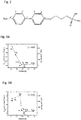
Fig. 2 shows the precursor molecule -
Fig. 3A and Fig. 3B shows the gas separation characteristics of a carbon nanomembrane according to this disclosure (Fig. 3A ) and in the prior art (Fig. 3B ). -
Figs. 4A to 4C show a diagram of the carbon nanomembranes during the manufacturing steps - The invention will now be described on the basis of the drawings. It will be understood that the embodiments and aspects of the invention described herein are only examples and do not limit the protective scope of the claims in any way. The invention is defined by the claims and their equivalents. It will be understood that features of one aspect or embodiment of the invention can be combined with a feature of a different aspect or aspects and/or embodiments of the invention.
- The method for fabrication of the carbon nanomembranes comprises three steps, as shown in
Fig. 1 . - In a
first step 100, a self-assembled monolayer from low molecular aromatic precursor molecules with at least one surface active group is prepared on a substrate of an aluminized polymer foil. The aluminized polymer foil is substantially flat and does not require substantial pre-treatment, unlike the gold layers and the silicon layers known in the art. - The term "low-molecular molecules" means such compounds that are not in an oligomer or polymer form. The term "aromatics" includes the term "heteroaromatics" in this disclosure, i.e. the term "aromatics" means aromatic compounds that contain no heteroatoms or one or more heteroatoms in at least one aromatic ring. The aromatic [precursor molecule] s [are] selected from the group consisting of phenyl, biphenyl, terphenyl, quaterphenyl, naphthalene, anthracene, pyrene, bipyridine, terpyridine, thiophene, bithienyl, terthienyl, pyrrole, and combinations thereof. The aluminized polymer foil could be, but is not limited to, an aluminized polyethylene terephthalate (PET) film.
- This preparation is done by wet chemistry (from a solution) or by organic vapour phase deposition of the precursor molecules onto the substrate. The surface-active group is a phosphonic acid group.
- It would be also possible to use films made of other polymers, such as polyethylene, polyester, polypropylene, polycarbonate, nylon, polyimide, polyaramide (aromatic amides), silane- and siloxane-based polymers like polydimethylsiloxane (PDMS), poly (vinyl trimethyl silane) etc., poly (phenylene oxide), polystyrene, poly (4-methyl pentene-1), polysulfone and others. Aluminium has the advantage that it is comparatively inexpensive. The PET is used as the polymer substrate because one can create a polymer substrate with a surface having a small degree of roughness.
- The molecules in the self-assembled monolayer are cross-linked in
step 110 by irradiation with low energy electrons (10-1000 eV). - The carbon nanomembrane is then released from the aluminized polymer film by means of a protective layer. The CNM/ metallised polymer structure formed in
step 110 is first coated with a protective layer, e.g. a layer of polymethylmethacrylate (PMMA) or other polymer instep 120 to form a sandwich structure. The coating can be performed by e.g. spin coating, drop casting, electrospinning Then the edges of the protective layer/CNM/ metallised polymer sandwich structure are cut instep 130 and the sandwich structure is let to float or is immersed instep 140 into an aqueous sodium hydroxide solution (preferably 5 % concentration) at preferably 50°C or 60°C temperature. This basic solution of sodium hydroxide etches simultaneously the aluminium film and the PET film, which allows the separation of the protective layer/CNM structure from the substrate. - After the aluminium film is completely etched away, the protective layer/CNM structure floats on the liquid/air interface of the solution and can be optionally transferred to a solid or perforated support in
step 150 to create a stack. The support can be of any kind, e.g. a porous polymer, a metallic grid, etc. - In a
last step 160, the protective layer can be optionally removed. For example, a PMMA-based protective layer could be dissolved by immersion of the stack in acetone. - It is also known that CuCl2 and KOH can be used as an etchant for the aluminium layer. However, the etching rate is much slower. In the case of CuCl2 the protective layer/CNM structure does not lift easily off the metallised polymer when the polymer is a PET foil. In this case, an additional slight dipping in 1-5% NaOH solution is necessary to promote the separation of the polymer PET layer from the protective layer/CNM.
- Should other metals (Au, Ag, Cu) be used, in methods not according to the invention, then a different etchant needs to be used. It is thought, for example, that a gold layer could be removed using aqua regia or an iodine solution.
- The substrate used in
step 100 is flexible and cheap. The role of the substrate is to reduce the material costs and allow upscaling of the production process. - The surface-active group of the aromatic precursor molecules described in this method is a phosphonic acid, which is known to be very stable in air and in water. Therefore, it does not require special equipment, work under inert atmosphere and preliminary drying and degassing of the organic solvent. These phosphorus-based organic compounds have strong chemical affinity towards aluminium, which rules out the necessity of harsh cleaning of the vessels, used for preparation of the self-assembled monolayer.
- The solution for the preparation of the self-assembled monolayer can be handled in air. The formation of the self-assembled monolayer happens in shorter time (e.g. less than 6 hours for a biphenyl-based self-assembled monolayer on the aluminized polymer substrate, in comparison to three days for a biphenyl-based self-assembled monolayer on a gold substrate according to the procedure used to date). The formed self-assembled monolayer from
step 100 is more stable in ambient environment. - It has been found that unlike prior art methods the solution does not substantially degrade and can be used multiple times.
- The process of releasing the carbon nanomembrane from the substrate does not involve hydrofluoric acid.
-
Figs. 4A to 4C show the various manufacturing methods. InFig. 4A a metallised polymer has a self-assembled monolayer placed on top of the metallised polymer film (step 100). The self-assembled monolayer is then irradiated with electrons to form the CNM/metallised polymer structure (step 110). -
Fig. 4B shows the subsequent step in which the CNM/metallised polymer structure is coated with a polymer film as the protective layer (step 120) which is then etched to form a protective layer/CNM structure. - In
Fig. 4C the protective layer/CNM structure can be left alone (top path), have a support layer attached (step 150, middle path) and /or then the protective layer removed (step 160, lower path). - The carbon nanomembranes can be used as ballistic membranes (separation according to the kinetic diameter of the particles) for gas separation and ultrafiltration. It is possible to control properties like the density and size distribution of intrinsic pores (pores formed during the fabrication without additional efforts like treatment of the substrate or formed membranes by e.g. ion bombardment or etching) by the selection of the precursor molecules and process parameters for the formation of the self-assembled monolayer by analogy with the methods described in ACS Nano, Vol. 7, No 8, 6489-6497.
- Preparation of a self-assembled monolayer of the precursor [3-([4'-Nitro-1,1'-biphenyl]-4-yloxy)-propyl]-phosphonic acid (as shown in
Fig. 2 ) onto an aluminized polyethylene terephthalate film as the substrate with a minimum thickness of the PET film of 75 microns and a thickness of the Al-layer of 14 nm. Preparation was done by immersion of the substrate into a solution of the precursor molecule in technical ethanol. - Crosslinking of the molecules in the self-assembled monolayer by irradiation with low energy electrons (100 eV) with an electron dose of 50 mC/cm2.
- Transfer of thus prepared carbon nanomembrane from the aluminized PET foil to a perforated polymer support. The CNM/A1/PET structure is first protected by a protective layer of polymethylmethacrylate (PMMA) attached to the surface by consecutively spin coating of 50 K and 950 K PMMA solutions. Then the edges of the PMMA/CNM/A1/PET sandwich structure were cut and the sandwich structure was immersed into or let to float on an aqueous 5%-NaOH solution at 60°C temperature. This basic solution etches simultaneously the aluminium film and the PET film, which allows the separation of the PMMA/CNM structure from the substrate. After the aluminium is completely etched away, the PMMA/CNM structure floats on the liquid/air interface and can be transferred to the porous polymer support. In a last step, the sacrificial PMMA-layer is dissolved by immersion of the stack in acetone.
- The so prepared composite membrane (
Figure 3A ) is very dense with a permeance of hydrogen lower compared to a traditionally prepared carbon nanomembrane (Figure 3B). Fig. 3B is taken from M. Ai, S. Shishatskiy, J. Wind, X. Zhang, C. T. Nottbohm, N. Mellech, A. Winter, H. Vieker, J. Qiu, K.-J. Dietz, A. Gölzhäuser, A. Beyer, Carbon Nanomembranes (CNMs) Supported by Polymer: Mechanics and Gas Permeation, Advanced. Materials 26, 3421 (2014). The cut-off kinetic diameter (gases with a smaller kinetic diameter can pass with high permeance, gases with larger kinetic diameter are hindered) is at around 2.8 Å also the lowest observed so far. This carbon nanomembrane is a starting point for tuning the gas separation characteristic for specific tasks by changing the structure of the precursor molecules to more complex shapes resulting in different packing densities of the self-assembled monolayers and different diameters of the intrinsic pores.
Claims (7)
- A method for the manufacture of a carbon nanomembrane comprising:preparing an aluminised polymer substrate;applying (100) on the aluminised polymer substrate a monolayer prepared from an aromatic molecule with at least one phosphonic acid group, wherein the aromatic precursor molecules are selected from the group consisting of phenyl, biphenyl, terphenyl, quaterphenyl, naphthalene, anthracene, pyrene, bipyridine, terpyridine, thiophene, bithienyl, terthienyl, pyrrole, and combinations thereof;cross-linking (110) by irradiation of the aromatic molecule with electrons having an energy between 10 and 1,000 eV to form a carbon nanomembrane;protecting the carbon nanomembrane by a protective polymer layer; andremoving the aluminised polymer substrate.
- The method of claim 1, further comprising placing of the carbon nanomembrane with the protective polymer layer on a support layer.
- The method of claim 2, further comprising removal (160) of the protective polymer layer.
- The method of anyone of the above claims, wherein the aluminised polymer substrate is an aluminised PET substrate.
- The method of any one of the above claims, wherein the protective polymer layer is made of PMMA.
- The method of any one of the above claims wherein the protective polymer layer is removed in acetone.
- The method of any one of claims 1 to 4 or 6, wherein the protective polymer layer is created by electrospinning a porous polymer.
Applications Claiming Priority (2)
| Application Number | Priority Date | Filing Date | Title |
|---|---|---|---|
| DE102015118412 | 2015-10-28 | ||
| PCT/EP2016/076016 WO2017072272A1 (en) | 2015-10-28 | 2016-10-28 | Method for manufacturing of a carbon nanomembrane |
Publications (3)
| Publication Number | Publication Date |
|---|---|
| EP3368197A1 EP3368197A1 (en) | 2018-09-05 |
| EP3368197B1 true EP3368197B1 (en) | 2021-07-14 |
| EP3368197B8 EP3368197B8 (en) | 2021-09-15 |
Family
ID=57209475
Family Applications (1)
| Application Number | Title | Priority Date | Filing Date |
|---|---|---|---|
| EP16788107.7A Active EP3368197B8 (en) | 2015-10-28 | 2016-10-28 | Method for manufacturing of a carbon nanomembrane |
Country Status (3)
| Country | Link |
|---|---|
| US (1) | US10646831B2 (en) |
| EP (1) | EP3368197B8 (en) |
| WO (1) | WO2017072272A1 (en) |
Families Citing this family (5)
| Publication number | Priority date | Publication date | Assignee | Title |
|---|---|---|---|---|
| LU100251B1 (en) | 2017-05-18 | 2019-01-04 | Cnm Tech Gmbh | A Method for Separating Fluidic Water from Impure Fluids and a Filter therefore |
| LU100276B1 (en) | 2017-06-02 | 2018-12-03 | Cnm Tech Gmbh | Immobilisation of nucleic acids on surfaces |
| LU100812B1 (en) * | 2018-05-29 | 2019-11-29 | Cnm Tech Gmbh | Carbon nanomembranes on porous materials |
| WO2020108781A1 (en) | 2018-11-30 | 2020-06-04 | Cnm Technologies Gmbh | Immobilisation of receptor molecules on surfaces by tetrazine ligation |
| WO2021170244A1 (en) * | 2020-02-27 | 2021-09-02 | Universiteit Leiden | Membrane and method of manufacture thereof |
Family Cites Families (19)
| Publication number | Priority date | Publication date | Assignee | Title |
|---|---|---|---|---|
| US3143364A (en) * | 1960-07-29 | 1964-08-04 | Allied Chem | Process for bonding polyethylene to non-porous surfaces and laminated polyethylene product |
| US3119358A (en) * | 1961-11-06 | 1964-01-28 | Robert T Colson | Shelter |
| US3380974A (en) * | 1964-10-30 | 1968-04-30 | Du Pont | Tetrafluoroethylene, isobutylene, carboxylic copolymers |
| US3653891A (en) * | 1969-12-31 | 1972-04-04 | Xerox Corp | Forms overlay technique using tesi |
| US5728431A (en) * | 1996-09-20 | 1998-03-17 | Texas A&M University System | Process for forming self-assembled polymer layers on a metal surface |
| US6468657B1 (en) * | 1998-12-04 | 2002-10-22 | The Regents Of The University Of California | Controllable ion-exchange membranes |
| DE19945935B4 (en) | 1999-09-24 | 2008-01-03 | Universität Heidelberg | Method for producing a surface-modified layer system |
| US20050221081A1 (en) * | 2004-03-23 | 2005-10-06 | Liu Gang-Yu | Stabilization of self-assembled monolayers |
| DE102007041820A1 (en) | 2007-09-03 | 2009-03-05 | Universität Bielefeld | graphite layers |
| WO2009149519A1 (en) * | 2008-06-12 | 2009-12-17 | Winwick Business Solutions Pty Ltd | System for cultivation and processing of microorganisms and products therefrom |
| CN102131571B (en) * | 2008-09-02 | 2014-03-05 | 东丽电池隔膜株式会社 | Microporous polymeric membranes, methods for making such membranes, and use of such membranes as battery separator film |
| DE102008046707A1 (en) | 2008-09-11 | 2010-03-18 | Universität Bielefeld | Fully crosslinked chemically structured monolayers |
| DE102009034575A1 (en) | 2009-07-24 | 2011-01-27 | Universität Bielefeld | Perforated membranes |
| US8679273B2 (en) * | 2010-02-01 | 2014-03-25 | Celestia, Llc | Systems and methods for providing vacuum encapsulation for climate control panels |
| WO2014100213A2 (en) * | 2012-12-18 | 2014-06-26 | Sabic Innovative Plastics Ip B.V. | High temperature melt integrity battery separators via spinning |
| WO2014152403A2 (en) * | 2013-03-15 | 2014-09-25 | Mcalister Technologies, Llc | Methods for joule-thompson cooling and heating of combustion chamber events and associated systems and apparatus |
| WO2014171624A1 (en) * | 2013-04-17 | 2014-10-23 | (주)에프티이앤이 | Electrospinning apparatus |
| GB2527561B (en) | 2014-06-26 | 2021-06-16 | Cnm Tech Gmbh | Multilayer structure |
| US9735366B2 (en) * | 2014-09-30 | 2017-08-15 | Cnm Technologies Gmbh | Heterostructure comprising a carbon nanomembrane |
-
2016
- 2016-10-28 EP EP16788107.7A patent/EP3368197B8/en active Active
- 2016-10-28 WO PCT/EP2016/076016 patent/WO2017072272A1/en not_active Ceased
-
2018
- 2018-04-24 US US15/961,145 patent/US10646831B2/en active Active
Non-Patent Citations (1)
| Title |
|---|
| None * |
Also Published As
| Publication number | Publication date |
|---|---|
| US20180236410A1 (en) | 2018-08-23 |
| EP3368197B8 (en) | 2021-09-15 |
| WO2017072272A1 (en) | 2017-05-04 |
| EP3368197A1 (en) | 2018-09-05 |
| US10646831B2 (en) | 2020-05-12 |
Similar Documents
| Publication | Publication Date | Title |
|---|---|---|
| US10646831B2 (en) | Method for manufacturing of a carbon nanomembrane | |
| Yang et al. | Removing contaminants from transferred CVD graphene | |
| US9840024B2 (en) | Method for the fabrication and transfer of graphene | |
| US20120267041A1 (en) | Method of forming multi-layer graphene | |
| US10017852B2 (en) | Method for treating graphene sheets for large-scale transfer using free-float method | |
| US20160137507A1 (en) | Large-area graphene transfer method | |
| TW201544453A (en) | Processes for forming composite structures with a two-dimensional material using a porous, non-sacrificial supporting layer | |
| KR20140106844A (en) | Encapsulation Film Comprising Thin Layer Composed of Graphene Oxide or Reduced Graphene Oxide and Method of Forming the Same | |
| CN106006546B (en) | A kind of method for shifting and controlling nanostructured | |
| CN104936892A (en) | Method for producing graphene film and graphene film produced thereby | |
| KR102347214B1 (en) | Graphene composite barrier film and method for manufacturing the same | |
| EP2991754B1 (en) | Method of manufacturing a partially freestanding two-dimensional crystal film and device comprising such a film | |
| KR101224290B1 (en) | Method for manufacturing block copolymer using graphene film and block copolymer manufactured by the same | |
| CN109534315B (en) | Amorphous carbon/nano-micron network film and preparation method thereof | |
| KR102958289B1 (en) | Transfer of nanostructures using crosslinkable copolymer films | |
| JP5878208B2 (en) | Nanostructure transfer method | |
| US11666866B2 (en) | Carbon nanomembranes on porous materials | |
| JP7197095B2 (en) | METHOD FOR FORMING GRAPHEN NANOPORES USING DETACHING AND DETACHING FUNCTIONAL GROUPS AND GRAPHEN SHEET HAVING GRAPHEN NANOPOSES FORMED BY THE METHOD | |
| KR102201148B1 (en) | Method for separating porous thin film and porous thin flim separated thereby | |
| KR20160147084A (en) | Transfering method of nanorod |
Legal Events
| Date | Code | Title | Description |
|---|---|---|---|
| STAA | Information on the status of an ep patent application or granted ep patent |
Free format text: STATUS: UNKNOWN |
|
| STAA | Information on the status of an ep patent application or granted ep patent |
Free format text: STATUS: THE INTERNATIONAL PUBLICATION HAS BEEN MADE |
|
| PUAI | Public reference made under article 153(3) epc to a published international application that has entered the european phase |
Free format text: ORIGINAL CODE: 0009012 |
|
| STAA | Information on the status of an ep patent application or granted ep patent |
Free format text: STATUS: REQUEST FOR EXAMINATION WAS MADE |
|
| 17P | Request for examination filed |
Effective date: 20180528 |
|
| AK | Designated contracting states |
Kind code of ref document: A1 Designated state(s): AL AT BE BG CH CY CZ DE DK EE ES FI FR GB GR HR HU IE IS IT LI LT LU LV MC MK MT NL NO PL PT RO RS SE SI SK SM TR |
|
| AX | Request for extension of the european patent |
Extension state: BA ME |
|
| DAV | Request for validation of the european patent (deleted) | ||
| DAX | Request for extension of the european patent (deleted) | ||
| STAA | Information on the status of an ep patent application or granted ep patent |
Free format text: STATUS: EXAMINATION IS IN PROGRESS |
|
| 17Q | First examination report despatched |
Effective date: 20190417 |
|
| REG | Reference to a national code |
Ref country code: DE Ref legal event code: R079 Ref document number: 602016060648 Country of ref document: DE Free format text: PREVIOUS MAIN CLASS: B01D0067000000 Ipc: B05D0001180000 |
|
| RIC1 | Information provided on ipc code assigned before grant |
Ipc: B01D 69/12 20060101ALI20200817BHEP Ipc: B01D 69/10 20060101ALI20200817BHEP Ipc: B05D 1/18 20060101AFI20200817BHEP Ipc: B01D 67/00 20060101ALI20200817BHEP |
|
| GRAP | Despatch of communication of intention to grant a patent |
Free format text: ORIGINAL CODE: EPIDOSNIGR1 |
|
| STAA | Information on the status of an ep patent application or granted ep patent |
Free format text: STATUS: GRANT OF PATENT IS INTENDED |
|
| INTG | Intention to grant announced |
Effective date: 20200928 |
|
| GRAJ | Information related to disapproval of communication of intention to grant by the applicant or resumption of examination proceedings by the epo deleted |
Free format text: ORIGINAL CODE: EPIDOSDIGR1 |
|
| STAA | Information on the status of an ep patent application or granted ep patent |
Free format text: STATUS: EXAMINATION IS IN PROGRESS |
|
| GRAP | Despatch of communication of intention to grant a patent |
Free format text: ORIGINAL CODE: EPIDOSNIGR1 |
|
| STAA | Information on the status of an ep patent application or granted ep patent |
Free format text: STATUS: GRANT OF PATENT IS INTENDED |
|
| INTC | Intention to grant announced (deleted) | ||
| INTG | Intention to grant announced |
Effective date: 20210203 |
|
| GRAS | Grant fee paid |
Free format text: ORIGINAL CODE: EPIDOSNIGR3 |
|
| GRAA | (expected) grant |
Free format text: ORIGINAL CODE: 0009210 |
|
| STAA | Information on the status of an ep patent application or granted ep patent |
Free format text: STATUS: THE PATENT HAS BEEN GRANTED |
|
| AK | Designated contracting states |
Kind code of ref document: B1 Designated state(s): AL AT BE BG CH CY CZ DE DK EE ES FI FR GB GR HR HU IE IS IT LI LT LU LV MC MK MT NL NO PL PT RO RS SE SI SK SM TR |
|
| REG | Reference to a national code |
Ref country code: GB Ref legal event code: FG4D |
|
| REG | Reference to a national code |
Ref country code: DE Ref legal event code: R096 Ref document number: 602016060648 Country of ref document: DE |
|
| REG | Reference to a national code |
Ref country code: IE Ref legal event code: FG4D |
|
| GRAT | Correction requested after decision to grant or after decision to maintain patent in amended form |
Free format text: ORIGINAL CODE: EPIDOSNCDEC |
|
| REG | Reference to a national code |
Ref country code: AT Ref legal event code: REF Ref document number: 1410242 Country of ref document: AT Kind code of ref document: T Effective date: 20210815 |
|
| REG | Reference to a national code |
Ref country code: DE Ref legal event code: R081 Ref document number: 602016060648 Country of ref document: DE Owner name: CNM TECHNOLOGIES GMBH, DE Free format text: FORMER OWNER: CNM TECHNOLOGIES GMBH, 33609 BIELEFELD, DE |
|
| REG | Reference to a national code |
Ref country code: CH Ref legal event code: PK Free format text: BERICHTIGUNG B8 |
|
| RAP4 | Party data changed (patent owner data changed or rights of a patent transferred) |
Owner name: CNM TECHNOLOGIES GMBH |
|
| REG | Reference to a national code |
Ref country code: LT Ref legal event code: MG9D |
|
| REG | Reference to a national code |
Ref country code: NL Ref legal event code: MP Effective date: 20210714 |
|
| REG | Reference to a national code |
Ref country code: AT Ref legal event code: MK05 Ref document number: 1410242 Country of ref document: AT Kind code of ref document: T Effective date: 20210714 |
|
| PG25 | Lapsed in a contracting state [announced via postgrant information from national office to epo] |
Ref country code: NL Free format text: LAPSE BECAUSE OF FAILURE TO SUBMIT A TRANSLATION OF THE DESCRIPTION OR TO PAY THE FEE WITHIN THE PRESCRIBED TIME-LIMIT Effective date: 20210714 Ref country code: NO Free format text: LAPSE BECAUSE OF FAILURE TO SUBMIT A TRANSLATION OF THE DESCRIPTION OR TO PAY THE FEE WITHIN THE PRESCRIBED TIME-LIMIT Effective date: 20211014 Ref country code: PT Free format text: LAPSE BECAUSE OF FAILURE TO SUBMIT A TRANSLATION OF THE DESCRIPTION OR TO PAY THE FEE WITHIN THE PRESCRIBED TIME-LIMIT Effective date: 20211115 Ref country code: HR Free format text: LAPSE BECAUSE OF FAILURE TO SUBMIT A TRANSLATION OF THE DESCRIPTION OR TO PAY THE FEE WITHIN THE PRESCRIBED TIME-LIMIT Effective date: 20210714 Ref country code: ES Free format text: LAPSE BECAUSE OF FAILURE TO SUBMIT A TRANSLATION OF THE DESCRIPTION OR TO PAY THE FEE WITHIN THE PRESCRIBED TIME-LIMIT Effective date: 20210714 Ref country code: FI Free format text: LAPSE BECAUSE OF FAILURE TO SUBMIT A TRANSLATION OF THE DESCRIPTION OR TO PAY THE FEE WITHIN THE PRESCRIBED TIME-LIMIT Effective date: 20210714 Ref country code: LT Free format text: LAPSE BECAUSE OF FAILURE TO SUBMIT A TRANSLATION OF THE DESCRIPTION OR TO PAY THE FEE WITHIN THE PRESCRIBED TIME-LIMIT Effective date: 20210714 Ref country code: BG Free format text: LAPSE BECAUSE OF FAILURE TO SUBMIT A TRANSLATION OF THE DESCRIPTION OR TO PAY THE FEE WITHIN THE PRESCRIBED TIME-LIMIT Effective date: 20211014 Ref country code: AT Free format text: LAPSE BECAUSE OF FAILURE TO SUBMIT A TRANSLATION OF THE DESCRIPTION OR TO PAY THE FEE WITHIN THE PRESCRIBED TIME-LIMIT Effective date: 20210714 Ref country code: SE Free format text: LAPSE BECAUSE OF FAILURE TO SUBMIT A TRANSLATION OF THE DESCRIPTION OR TO PAY THE FEE WITHIN THE PRESCRIBED TIME-LIMIT Effective date: 20210714 Ref country code: RS Free format text: LAPSE BECAUSE OF FAILURE TO SUBMIT A TRANSLATION OF THE DESCRIPTION OR TO PAY THE FEE WITHIN THE PRESCRIBED TIME-LIMIT Effective date: 20210714 |
|
| PG25 | Lapsed in a contracting state [announced via postgrant information from national office to epo] |
Ref country code: PL Free format text: LAPSE BECAUSE OF FAILURE TO SUBMIT A TRANSLATION OF THE DESCRIPTION OR TO PAY THE FEE WITHIN THE PRESCRIBED TIME-LIMIT Effective date: 20210714 Ref country code: LV Free format text: LAPSE BECAUSE OF FAILURE TO SUBMIT A TRANSLATION OF THE DESCRIPTION OR TO PAY THE FEE WITHIN THE PRESCRIBED TIME-LIMIT Effective date: 20210714 Ref country code: GR Free format text: LAPSE BECAUSE OF FAILURE TO SUBMIT A TRANSLATION OF THE DESCRIPTION OR TO PAY THE FEE WITHIN THE PRESCRIBED TIME-LIMIT Effective date: 20211015 |
|
| REG | Reference to a national code |
Ref country code: DE Ref legal event code: R097 Ref document number: 602016060648 Country of ref document: DE |
|
| PG25 | Lapsed in a contracting state [announced via postgrant information from national office to epo] |
Ref country code: DK Free format text: LAPSE BECAUSE OF FAILURE TO SUBMIT A TRANSLATION OF THE DESCRIPTION OR TO PAY THE FEE WITHIN THE PRESCRIBED TIME-LIMIT Effective date: 20210714 |
|
| PLBE | No opposition filed within time limit |
Free format text: ORIGINAL CODE: 0009261 |
|
| STAA | Information on the status of an ep patent application or granted ep patent |
Free format text: STATUS: NO OPPOSITION FILED WITHIN TIME LIMIT |
|
| REG | Reference to a national code |
Ref country code: CH Ref legal event code: PL |
|
| PG25 | Lapsed in a contracting state [announced via postgrant information from national office to epo] |
Ref country code: SM Free format text: LAPSE BECAUSE OF FAILURE TO SUBMIT A TRANSLATION OF THE DESCRIPTION OR TO PAY THE FEE WITHIN THE PRESCRIBED TIME-LIMIT Effective date: 20210714 Ref country code: SK Free format text: LAPSE BECAUSE OF FAILURE TO SUBMIT A TRANSLATION OF THE DESCRIPTION OR TO PAY THE FEE WITHIN THE PRESCRIBED TIME-LIMIT Effective date: 20210714 Ref country code: RO Free format text: LAPSE BECAUSE OF FAILURE TO SUBMIT A TRANSLATION OF THE DESCRIPTION OR TO PAY THE FEE WITHIN THE PRESCRIBED TIME-LIMIT Effective date: 20210714 Ref country code: EE Free format text: LAPSE BECAUSE OF FAILURE TO SUBMIT A TRANSLATION OF THE DESCRIPTION OR TO PAY THE FEE WITHIN THE PRESCRIBED TIME-LIMIT Effective date: 20210714 Ref country code: CZ Free format text: LAPSE BECAUSE OF FAILURE TO SUBMIT A TRANSLATION OF THE DESCRIPTION OR TO PAY THE FEE WITHIN THE PRESCRIBED TIME-LIMIT Effective date: 20210714 Ref country code: AL Free format text: LAPSE BECAUSE OF FAILURE TO SUBMIT A TRANSLATION OF THE DESCRIPTION OR TO PAY THE FEE WITHIN THE PRESCRIBED TIME-LIMIT Effective date: 20210714 |
|
| 26N | No opposition filed |
Effective date: 20220419 |
|
| REG | Reference to a national code |
Ref country code: BE Ref legal event code: MM Effective date: 20211031 |
|
| GBPC | Gb: european patent ceased through non-payment of renewal fee |
Effective date: 20211028 |
|
| PG25 | Lapsed in a contracting state [announced via postgrant information from national office to epo] |
Ref country code: MC Free format text: LAPSE BECAUSE OF FAILURE TO SUBMIT A TRANSLATION OF THE DESCRIPTION OR TO PAY THE FEE WITHIN THE PRESCRIBED TIME-LIMIT Effective date: 20210714 |
|
| PG25 | Lapsed in a contracting state [announced via postgrant information from national office to epo] |
Ref country code: LU Free format text: LAPSE BECAUSE OF NON-PAYMENT OF DUE FEES Effective date: 20211028 Ref country code: IT Free format text: LAPSE BECAUSE OF FAILURE TO SUBMIT A TRANSLATION OF THE DESCRIPTION OR TO PAY THE FEE WITHIN THE PRESCRIBED TIME-LIMIT Effective date: 20210714 Ref country code: GB Free format text: LAPSE BECAUSE OF NON-PAYMENT OF DUE FEES Effective date: 20211028 Ref country code: BE Free format text: LAPSE BECAUSE OF NON-PAYMENT OF DUE FEES Effective date: 20211031 |
|
| PG25 | Lapsed in a contracting state [announced via postgrant information from national office to epo] |
Ref country code: LI Free format text: LAPSE BECAUSE OF NON-PAYMENT OF DUE FEES Effective date: 20211031 Ref country code: CH Free format text: LAPSE BECAUSE OF NON-PAYMENT OF DUE FEES Effective date: 20211031 |
|
| PG25 | Lapsed in a contracting state [announced via postgrant information from national office to epo] |
Ref country code: FR Free format text: LAPSE BECAUSE OF NON-PAYMENT OF DUE FEES Effective date: 20211031 |
|
| PG25 | Lapsed in a contracting state [announced via postgrant information from national office to epo] |
Ref country code: IE Free format text: LAPSE BECAUSE OF NON-PAYMENT OF DUE FEES Effective date: 20211028 |
|
| PG25 | Lapsed in a contracting state [announced via postgrant information from national office to epo] |
Ref country code: HU Free format text: LAPSE BECAUSE OF FAILURE TO SUBMIT A TRANSLATION OF THE DESCRIPTION OR TO PAY THE FEE WITHIN THE PRESCRIBED TIME-LIMIT; INVALID AB INITIO Effective date: 20161028 |
|
| PG25 | Lapsed in a contracting state [announced via postgrant information from national office to epo] |
Ref country code: CY Free format text: LAPSE BECAUSE OF FAILURE TO SUBMIT A TRANSLATION OF THE DESCRIPTION OR TO PAY THE FEE WITHIN THE PRESCRIBED TIME-LIMIT Effective date: 20210714 |
|
| P01 | Opt-out of the competence of the unified patent court (upc) registered |
Effective date: 20230601 |
|
| PG25 | Lapsed in a contracting state [announced via postgrant information from national office to epo] |
Ref country code: MK Free format text: LAPSE BECAUSE OF FAILURE TO SUBMIT A TRANSLATION OF THE DESCRIPTION OR TO PAY THE FEE WITHIN THE PRESCRIBED TIME-LIMIT Effective date: 20210714 |
|
| PG25 | Lapsed in a contracting state [announced via postgrant information from national office to epo] |
Ref country code: TR Free format text: LAPSE BECAUSE OF FAILURE TO SUBMIT A TRANSLATION OF THE DESCRIPTION OR TO PAY THE FEE WITHIN THE PRESCRIBED TIME-LIMIT Effective date: 20210714 |
|
| PG25 | Lapsed in a contracting state [announced via postgrant information from national office to epo] |
Ref country code: MT Free format text: LAPSE BECAUSE OF FAILURE TO SUBMIT A TRANSLATION OF THE DESCRIPTION OR TO PAY THE FEE WITHIN THE PRESCRIBED TIME-LIMIT Effective date: 20210714 |
|
| PGFP | Annual fee paid to national office [announced via postgrant information from national office to epo] |
Ref country code: DE Payment date: 20251027 Year of fee payment: 10 |