EP3368108B1 - Medicament delivery device - Google Patents
Medicament delivery device Download PDFInfo
- Publication number
- EP3368108B1 EP3368108B1 EP16782225.3A EP16782225A EP3368108B1 EP 3368108 B1 EP3368108 B1 EP 3368108B1 EP 16782225 A EP16782225 A EP 16782225A EP 3368108 B1 EP3368108 B1 EP 3368108B1
- Authority
- EP
- European Patent Office
- Prior art keywords
- medicament delivery
- delivery device
- sensor
- force
- monitoring unit
- Prior art date
- Legal status (The legal status is an assumption and is not a legal conclusion. Google has not performed a legal analysis and makes no representation as to the accuracy of the status listed.)
- Active
Links
- 239000003814 drug Substances 0.000 title claims description 99
- 238000012544 monitoring process Methods 0.000 claims description 38
- 238000004891 communication Methods 0.000 claims description 20
- 238000012546 transfer Methods 0.000 claims description 19
- 230000003287 optical effect Effects 0.000 claims description 11
- 238000005516 engineering process Methods 0.000 claims description 7
- 230000000007 visual effect Effects 0.000 claims description 3
- 238000002347 injection Methods 0.000 description 11
- 239000007924 injection Substances 0.000 description 11
- 238000000418 atomic force spectrum Methods 0.000 description 5
- 239000000243 solution Substances 0.000 description 5
- 230000008901 benefit Effects 0.000 description 4
- 229940079593 drug Drugs 0.000 description 3
- 238000013461 design Methods 0.000 description 2
- 230000004048 modification Effects 0.000 description 2
- 238000012986 modification Methods 0.000 description 2
- 230000009471 action Effects 0.000 description 1
- 239000000443 aerosol Substances 0.000 description 1
- 230000008859 change Effects 0.000 description 1
- 238000004590 computer program Methods 0.000 description 1
- 230000008878 coupling Effects 0.000 description 1
- 238000010168 coupling process Methods 0.000 description 1
- 238000005859 coupling reaction Methods 0.000 description 1
- 230000003247 decreasing effect Effects 0.000 description 1
- 230000001419 dependent effect Effects 0.000 description 1
- 238000001514 detection method Methods 0.000 description 1
- 230000002349 favourable effect Effects 0.000 description 1
- 238000003780 insertion Methods 0.000 description 1
- 230000037431 insertion Effects 0.000 description 1
- 239000007788 liquid Substances 0.000 description 1
- 238000005259 measurement Methods 0.000 description 1
- 230000007246 mechanism Effects 0.000 description 1
- 230000002093 peripheral effect Effects 0.000 description 1
- 239000000843 powder Substances 0.000 description 1
- 239000002699 waste material Substances 0.000 description 1
Images


Classifications
-
- A—HUMAN NECESSITIES
- A61—MEDICAL OR VETERINARY SCIENCE; HYGIENE
- A61M—DEVICES FOR INTRODUCING MEDIA INTO, OR ONTO, THE BODY; DEVICES FOR TRANSDUCING BODY MEDIA OR FOR TAKING MEDIA FROM THE BODY; DEVICES FOR PRODUCING OR ENDING SLEEP OR STUPOR
- A61M5/00—Devices for bringing media into the body in a subcutaneous, intra-vascular or intramuscular way; Accessories therefor, e.g. filling or cleaning devices, arm-rests
- A61M5/50—Devices for bringing media into the body in a subcutaneous, intra-vascular or intramuscular way; Accessories therefor, e.g. filling or cleaning devices, arm-rests having means for preventing re-use, or for indicating if defective, used, tampered with or unsterile
- A61M5/5086—Devices for bringing media into the body in a subcutaneous, intra-vascular or intramuscular way; Accessories therefor, e.g. filling or cleaning devices, arm-rests having means for preventing re-use, or for indicating if defective, used, tampered with or unsterile for indicating if defective, used, tampered with or unsterile
-
- A—HUMAN NECESSITIES
- A61—MEDICAL OR VETERINARY SCIENCE; HYGIENE
- A61M—DEVICES FOR INTRODUCING MEDIA INTO, OR ONTO, THE BODY; DEVICES FOR TRANSDUCING BODY MEDIA OR FOR TAKING MEDIA FROM THE BODY; DEVICES FOR PRODUCING OR ENDING SLEEP OR STUPOR
- A61M5/00—Devices for bringing media into the body in a subcutaneous, intra-vascular or intramuscular way; Accessories therefor, e.g. filling or cleaning devices, arm-rests
- A61M5/178—Syringes
- A61M5/31—Details
- A61M5/315—Pistons; Piston-rods; Guiding, blocking or restricting the movement of the rod or piston; Appliances on the rod for facilitating dosing ; Dosing mechanisms
- A61M5/31565—Administration mechanisms, i.e. constructional features, modes of administering a dose
- A61M5/31566—Means improving security or handling thereof
-
- A—HUMAN NECESSITIES
- A61—MEDICAL OR VETERINARY SCIENCE; HYGIENE
- A61M—DEVICES FOR INTRODUCING MEDIA INTO, OR ONTO, THE BODY; DEVICES FOR TRANSDUCING BODY MEDIA OR FOR TAKING MEDIA FROM THE BODY; DEVICES FOR PRODUCING OR ENDING SLEEP OR STUPOR
- A61M5/00—Devices for bringing media into the body in a subcutaneous, intra-vascular or intramuscular way; Accessories therefor, e.g. filling or cleaning devices, arm-rests
- A61M5/178—Syringes
- A61M5/20—Automatic syringes, e.g. with automatically actuated piston rod, with automatic needle injection, filling automatically
- A61M5/2033—Spring-loaded one-shot injectors with or without automatic needle insertion
-
- A—HUMAN NECESSITIES
- A61—MEDICAL OR VETERINARY SCIENCE; HYGIENE
- A61M—DEVICES FOR INTRODUCING MEDIA INTO, OR ONTO, THE BODY; DEVICES FOR TRANSDUCING BODY MEDIA OR FOR TAKING MEDIA FROM THE BODY; DEVICES FOR PRODUCING OR ENDING SLEEP OR STUPOR
- A61M5/00—Devices for bringing media into the body in a subcutaneous, intra-vascular or intramuscular way; Accessories therefor, e.g. filling or cleaning devices, arm-rests
- A61M5/178—Syringes
- A61M5/31—Details
- A61M5/315—Pistons; Piston-rods; Guiding, blocking or restricting the movement of the rod or piston; Appliances on the rod for facilitating dosing ; Dosing mechanisms
- A61M5/31511—Piston or piston-rod constructions, e.g. connection of piston with piston-rod
-
- A—HUMAN NECESSITIES
- A61—MEDICAL OR VETERINARY SCIENCE; HYGIENE
- A61M—DEVICES FOR INTRODUCING MEDIA INTO, OR ONTO, THE BODY; DEVICES FOR TRANSDUCING BODY MEDIA OR FOR TAKING MEDIA FROM THE BODY; DEVICES FOR PRODUCING OR ENDING SLEEP OR STUPOR
- A61M5/00—Devices for bringing media into the body in a subcutaneous, intra-vascular or intramuscular way; Accessories therefor, e.g. filling or cleaning devices, arm-rests
- A61M5/178—Syringes
- A61M5/31—Details
- A61M5/315—Pistons; Piston-rods; Guiding, blocking or restricting the movement of the rod or piston; Appliances on the rod for facilitating dosing ; Dosing mechanisms
- A61M5/31565—Administration mechanisms, i.e. constructional features, modes of administering a dose
- A61M5/31576—Constructional features or modes of drive mechanisms for piston rods
-
- A—HUMAN NECESSITIES
- A61—MEDICAL OR VETERINARY SCIENCE; HYGIENE
- A61M—DEVICES FOR INTRODUCING MEDIA INTO, OR ONTO, THE BODY; DEVICES FOR TRANSDUCING BODY MEDIA OR FOR TAKING MEDIA FROM THE BODY; DEVICES FOR PRODUCING OR ENDING SLEEP OR STUPOR
- A61M5/00—Devices for bringing media into the body in a subcutaneous, intra-vascular or intramuscular way; Accessories therefor, e.g. filling or cleaning devices, arm-rests
- A61M5/178—Syringes
- A61M5/31—Details
- A61M2005/3125—Details specific display means, e.g. to indicate dose setting
- A61M2005/3126—Specific display means related to dosing
-
- A—HUMAN NECESSITIES
- A61—MEDICAL OR VETERINARY SCIENCE; HYGIENE
- A61M—DEVICES FOR INTRODUCING MEDIA INTO, OR ONTO, THE BODY; DEVICES FOR TRANSDUCING BODY MEDIA OR FOR TAKING MEDIA FROM THE BODY; DEVICES FOR PRODUCING OR ENDING SLEEP OR STUPOR
- A61M2205/00—General characteristics of the apparatus
- A61M2205/33—Controlling, regulating or measuring
- A61M2205/3306—Optical measuring means
-
- A—HUMAN NECESSITIES
- A61—MEDICAL OR VETERINARY SCIENCE; HYGIENE
- A61M—DEVICES FOR INTRODUCING MEDIA INTO, OR ONTO, THE BODY; DEVICES FOR TRANSDUCING BODY MEDIA OR FOR TAKING MEDIA FROM THE BODY; DEVICES FOR PRODUCING OR ENDING SLEEP OR STUPOR
- A61M2205/00—General characteristics of the apparatus
- A61M2205/33—Controlling, regulating or measuring
- A61M2205/332—Force measuring means
-
- A—HUMAN NECESSITIES
- A61—MEDICAL OR VETERINARY SCIENCE; HYGIENE
- A61M—DEVICES FOR INTRODUCING MEDIA INTO, OR ONTO, THE BODY; DEVICES FOR TRANSDUCING BODY MEDIA OR FOR TAKING MEDIA FROM THE BODY; DEVICES FOR PRODUCING OR ENDING SLEEP OR STUPOR
- A61M2205/00—General characteristics of the apparatus
- A61M2205/35—Communication
- A61M2205/3576—Communication with non implanted data transmission devices, e.g. using external transmitter or receiver
- A61M2205/3584—Communication with non implanted data transmission devices, e.g. using external transmitter or receiver using modem, internet or bluetooth
-
- A—HUMAN NECESSITIES
- A61—MEDICAL OR VETERINARY SCIENCE; HYGIENE
- A61M—DEVICES FOR INTRODUCING MEDIA INTO, OR ONTO, THE BODY; DEVICES FOR TRANSDUCING BODY MEDIA OR FOR TAKING MEDIA FROM THE BODY; DEVICES FOR PRODUCING OR ENDING SLEEP OR STUPOR
- A61M2205/00—General characteristics of the apparatus
- A61M2205/35—Communication
- A61M2205/3576—Communication with non implanted data transmission devices, e.g. using external transmitter or receiver
- A61M2205/3592—Communication with non implanted data transmission devices, e.g. using external transmitter or receiver using telemetric means, e.g. radio or optical transmission
-
- A—HUMAN NECESSITIES
- A61—MEDICAL OR VETERINARY SCIENCE; HYGIENE
- A61M—DEVICES FOR INTRODUCING MEDIA INTO, OR ONTO, THE BODY; DEVICES FOR TRANSDUCING BODY MEDIA OR FOR TAKING MEDIA FROM THE BODY; DEVICES FOR PRODUCING OR ENDING SLEEP OR STUPOR
- A61M2205/00—General characteristics of the apparatus
- A61M2205/58—Means for facilitating use, e.g. by people with impaired vision
- A61M2205/581—Means for facilitating use, e.g. by people with impaired vision by audible feedback
-
- A—HUMAN NECESSITIES
- A61—MEDICAL OR VETERINARY SCIENCE; HYGIENE
- A61M—DEVICES FOR INTRODUCING MEDIA INTO, OR ONTO, THE BODY; DEVICES FOR TRANSDUCING BODY MEDIA OR FOR TAKING MEDIA FROM THE BODY; DEVICES FOR PRODUCING OR ENDING SLEEP OR STUPOR
- A61M2205/00—General characteristics of the apparatus
- A61M2205/58—Means for facilitating use, e.g. by people with impaired vision
- A61M2205/582—Means for facilitating use, e.g. by people with impaired vision by tactile feedback
-
- A—HUMAN NECESSITIES
- A61—MEDICAL OR VETERINARY SCIENCE; HYGIENE
- A61M—DEVICES FOR INTRODUCING MEDIA INTO, OR ONTO, THE BODY; DEVICES FOR TRANSDUCING BODY MEDIA OR FOR TAKING MEDIA FROM THE BODY; DEVICES FOR PRODUCING OR ENDING SLEEP OR STUPOR
- A61M2205/00—General characteristics of the apparatus
- A61M2205/58—Means for facilitating use, e.g. by people with impaired vision
- A61M2205/583—Means for facilitating use, e.g. by people with impaired vision by visual feedback
Definitions
- the present invention relates to a device for sensing forces that occur during operation of a medicament delivery device.
- medicament delivery devices There is an ever increasing demand for obtaining information from different devices and apparatuses that we use daily, and medicament delivery devices are no exception to that demand. Because of this, a number of medicament delivery devices have been developed that contain "smart" features such as sensor and monitoring systems, communication circuits, man-machine interfaces that can present information regarding the status of the medicament delivery device, for instance.
- a further drawback is if medicament delivery devices that are approved by national drug agencies and are out on the market were to be provided with added functionality built into the interior of the medicament delivery device. This would then require a new approval by the national drug agencies, which might take a number of years to obtain. It would be a better and simpler solution if the added functionality could be arranged outside the medicament delivery devices and not built into them.
- One feature of particular interest in medicament delivery devices is to monitor the movement of components or elements of a drive unit, such as for example a plunger rod that is acting on a medicament container during delivery of a dose of medicament.
- a drive unit such as for example a plunger rod that is acting on a medicament container during delivery of a dose of medicament.
- these components are arranged inside a housing of a medicament delivery device, access to them may be difficult without major modifications.
- Document EP 2190506 discloses a medicament delivery device arranged with a monitoring unit.
- the electronics unit is arranged as an attachable auxiliary device provided with a reader of RFID-sensors.
- RFID-sensor is comprised in a sensor system that is placed inside the medicament delivery device.
- Document WO 2015/136564 discloses an add-on module for a conventional, manually operable, syringe.
- the add-on is arranged with a number of different sensors where one type is optical sensors capable of controlling the amount of liquid in the syringe.
- Another type of sensor is an accelerometer capable of measuring the inclination of the syringe at which the injection is made and temperature sensor for monitoring the temperature of the syringe.
- distal part/end refers to the part/end of the device, or the parts/ends of the members thereof, which under use of the device, is located the furthest away from a delivery site of a patient.
- proximal part/end refers to the part/end of the device, or the parts/ends of the members thereof, which under use of the device is located closest to the delivery site of the patient.
- smart devices may include electronic devices that are provided with processors that are capable of running computer programs as well as storage space to store programs as well as data retrieved from different external sources. It is further to be understood that the smart devices are provided with communication systems that are capable of communicating with data networks in order to access different databases. It is to be understood that databases may be accessed via the internet, so called cloud services, and/or databases that are connected directly to and accessed via local area networks. It is further to be understood that the smart devices in this context comprise some sort of human-machine interface for two-way communication. The human-machine interface may comprise displays, keyboards, microphones, loudspeakers, I/O-ports for connection of peripherals. Further the smart devices may be provided with antennas for wireless communication with the networks. Also, the smart devices may be arranged with receiving and transmitting mechanisms capable of communicating with Near Range Wireless Communication circuits as well as programs capable of establishing and handling the communication with these circuits.
- medicament delivery devices may include a number of devices capable of delivering certain doses of medicament to a user, such as e.g. injection devices with or without injection needles, inhalers of all kinds, such as powder, aerosol-driven, gas, nebulizers having mouth or nasal pieces, dispensers for medicament in tablet form, eye dispensers, etc.
- the medicament delivery devices may be of either disposable type or re-usable type and may be provided with medicament containers suitably arranged for specific drugs in specific forms.
- the aim of the present invention is to remedy the drawbacks of the state of the art devices. This aim is obtained with a medicament delivery device according to the features of the independent patent claim. Preferable embodiments of the invention form the subject of the dependent patent claims.
- a medicament delivery device comprising a housing provided with a power unit.
- the power unit may comprise a drive force element; which drive force element may be arranged to act on an actuation element such as a plunger rod.
- the plunger rod may in turn be arranged to act on a stopper of a medicament container arranged in the housing.
- the medicament delivery device may further comprise a monitoring unit, where the monitoring unit is detachably attached to the housing. Further at least one sensor may be arranged in the monitoring unit, where the at least one sensor is operably arranged to monitor the power unit for obtaining information regarding status of the medicament delivery device.
- the medicament delivery device does not have to be modified in any major way in order to obtain a monitoring function.
- the monitoring unit since the monitoring unit is detachable, it may be moved between different medicament delivery devices.
- disposable medicament delivery devices may be arranged with monitoring functions, which functions may be re-used many times by attaching and detaching the monitoring unit to different devices while discarding the disposable medicament delivery devices after use.
- the at least one sensor may comprise a force sensor arranged to monitor the force from the drive force element.
- the medicament delivery device may further comprise a transfer element operably connected to the drive force element for transferring the force from the drive force element to the force sensor of the monitoring unit.
- the medicament delivery device may be arranged with a transfer element that can transfer the force from the interior of the housing to the outside.
- the at least one sensor may comprise an optical sensor arranged to monitor the movement of the plunger rod.
- the housing may be arranged with an opening through which the optical sensor may monitor the movement of the plunger rod.
- the monitoring unit may further comprise a communication element for providing information to an external receiver.
- the external receiver may be the user of the medicament delivery device, wherein the user may be provided with information regarding status of the medicament delivery device. This information may for example be that an injection sequence has started and/or that the injection sequence has ended and that it is safe to remove the medicament delivery device from the dose delivery site.
- the communication element may comprise members for providing visual, audible and/or tactile information.
- the communication element may comprise a circuit for near range wireless communication such as NFC- , RFID-, ANT-, Zigbee- or Bluetooth technology.
- NFC- near range wireless communication
- RFID- RFID-
- ANT- ANT-
- Zigbee- Zigbee-
- Bluetooth Bluetooth
- the medicament delivery device is preferably a disposable device that is to be discarded after use.
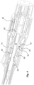
- the medicament delivery device comprises a housing 10 in which a transfer element 12 is arranged.
- the transfer element 12 is operably connected to components and functions of the medicament delivery device.
- the transfer element 12 has a generally disk-shaped body 14 that is arranged movable in a longitudinal direction in a recess 16 in a distal end wall 18 of the housing 10.
- a distally directed surface of the disk-shaped body 14 of the transfer element 12 is arranged with a pin 20 or the like protrusion that is positioned in a passage 22 in the distal end wall 18, whereby the pin 20 extends a distance outside the end wall 18 when the transfer element 12 is in its most distal position.
- a drive unit may preferably be arranged in the medicament delivery device.
- the drive unit may comprise a drive force element such as a drive spring 24, which may be an injection sequence drive spring 24, has a distal end acting on a proximal surface of the disk-shaped body 14 of the transfer element 12.
- a drive spring 24 is acting on the transfer element 12 via a support disk 26 attached or integral to a distal end of a spring guide rod 28.
- the transfer element could be integrated with the support disk in that the disk-shaped body 14 is the same component as the support disk 26.
- the drive spring 24 is tensioned and the transfer element 12 is forced to its most distal position with the pin 20 extending a distance outside the end wall 18.
- the proximal end of the drive spring is preferably operably connected to an actuation element such as a plunger rod 29, which in turn is capable of acting on a stopper of a medicament container such that when the drive spring is activated, the plunger rod is moved in the proximal direction, moving the stopper with it, thus performing a dose delivery sequence.
- a monitoring unit 30, Fig. 2 is arranged to the medicament delivery device.
- the monitoring unit 30 is designed as an attachable unit having a housing 31 that can be releasably attached to the distal end of the medicament delivery device.
- the monitoring unit 30 and the medicament delivery device are arranged with suitable attachment elements (not shown), which attachment elements could have a number of designs and configurations, such as for example threads, bayonet couplings, snap-in fittings etc.
- the monitoring unit 30 is arranged with a force sensor 32 placed such that it is in contact with the pin 20 of the transfer element 12 when the monitoring unit 30 is attached to the medicament delivery device as seen in Fig. 2 .
- the force sensor 32 may be of a design that can transform mechanical forces exerted on the force sensor 32 to some sort of electric signal or impulse, such as e.g. a piezo-electric sensor or a strain gauge.
- the monitoring unit 30 may preferably be arranged with electronic circuits 34 to which the force sensor 32 is operably connected. In order to operate the electronics circuit 34, a suitable power source may be arranged, such as a button cell 36 or the like.
- the monitoring unit 30 may be arranged with suitable communication elements 38 for providing information to a user or to other persons that require information regarding the status of particular medicament delivery devices.
- the monitoring unit 30 is arranged with a communication element in the form of a user interface 40 that may comprise visual displays and/or light sources and/or loudspeakers and/or tactile information providers such as vibrating elements.
- the communication element of the monitoring unit may comprise some sort of wireless communication function, such as near range wireless communication technologies integrated in the electronics circuit. These may for instance be NFC-tags, RFID-tags, Ant-circuits, Zigbee-circuits, which are capable of transmitting information to external receivers over short distances.
- NFC-tags may be used, the monitoring unit may be operably connected to a smart device that is NFC-enabled. When such a smart device is held close to the monitoring unit, the NFC-tag may be energized and be made to transmit information to the smart device.
- Bluetooth Another type of technology that may be used is Bluetooth.
- a large number of devices are capable of communicating with each other via Bluetooth technologies and an advantage is thereby that the medicament delivery device with the monitoring unit does not have to be very close to a receiver such as a smart device.
- the monitoring unit is arranged with a force sensor.
- the force sensor is capable of measuring the force from the drive spring via the transfer element.
- the force of the drive spring will move a stopper inside a medicament container, whereby a dose of medicament is delivered through a medicament delivery member attached to the medicament container.
- the movement of the stopper by the drive spring will cause the drive spring to extend in the longitudinal direction, whereby its deliverable force is gradually reduced.
- the changes in the force output from the drive spring is sensed by the force sensor, which may be used as information regarding the change of status or the progress of the medicament delivery device operation.
- the force sensor when the force sensor detects a force that falls below a certain threshold, it may trigger a signal to the electronics. Further, the sensor may detect when the force starts to decrease as the plunger rod begins to move from a stationary state, indicating a start of a dose delivery sequence. Also, if the force sensor detects that the decrease in force from the drive spring has ended, due to a stop of the stopper at the end of the dose delivery operation, it may trigger a signal to the electronics. The electronics may then be programmed such that it will alert the user that it is safe to remove the medicament delivery device from the dose delivery site. Further information that the sensor may provide is the complete force curve during a complete dose delivery sequence.
- This force curve may be compared to force curves of pretested and normally functioning medicament containers to detect possible injection problems of the medicament delivery device such as siliconization problems or incomplete injections, e.g. due to internal friction of the medicament container exceeding the available spring force.
- the force curve may also indicate if the injection operation was made in air instead of in tissue, leading to different force curves.
- Figure 3 discloses a variant of the present invention.
- the medicament delivery device is arranged with an opening 50 providing access to the interior of the medicament delivery device and to components that are moving during operation of the medicament delivery device, such as for example a plunger rod 52 that during a dose delivery operation moves in the longitudinal direction by e.g. a drive spring, acting on the stopper of a medicament container for delivering a dose of medicament.
- a plunger rod 52 that during a dose delivery operation moves in the longitudinal direction by e.g. a drive spring, acting on the stopper of a medicament container for delivering a dose of medicament.
- the monitoring unit 30 may be arranged with an optical sensor 54 that is capable of providing a light beam 56 that is reflected back, detecting movement of components, such as the plunger rod 52 of the medicament delivery device which is moving during a dose delivery sequence.
- the moving component may be arranged with suitable patterns, facilitating the detection of movement.
- the optical sensor 54 may, as mentioned above, be operably connected to an electronics circuit 34.
- the optical sensor may register the start of the movement, indicating e.g. a start of the dose delivery sequence as well as the stop of the movement, indicating a stop of the dose delivery sequence. Further the speed of the movement during the dose delivery sequence may be monitored and compared to movement patterns of pretested and normally functioning medicament container for detecting possible injection problems of the medicament delivery device.
- Figures 4 to 8 show a further example of a medicament delivery device that may be arranged with a monitoring unit 30.
- the medicament delivery device is arranged with a flat spiral spring 60 that is wound around a drive element 62 with an outer end attached to a housing part (not shown).
- the drive element 62 is operably connected to a drive nut 64 provided with a central passage 66 having threads 68. These threads 68 are arranged to cooperate with threads 70 on an outer surface of an elongated plunger rod 72.
- the drive nut 64 is further arranged with a distally directed support surface 74, Fig. 7 , that is in contact with a proximally directed support wall 76, Fig. 5 , of a chassis 78 of the medicament delivery device.
- the spiral spring 60 will rotate the drive element 62 and thus the drive nut 64.
- the rotation of the drive nut 64 will cause the plunger rod 72 to move in the proximal direction and to act on a medicament container for expelling a dose of medicament.
- a monitoring unit 30 may be arranged to the medicament delivery device, which monitoring unit is operably connected to a sensor 80, Fig. 4 .
- the sensor 80 is a force sensor that is capable of sensing the force from the drive nut 64.
- a passage 82, Fig. 5 is arranged in the support wall 76.
- the drive nut 64 is arranged with a distally directed pin 84 that extends in the passage 82 of the support wall 76.
- the force sensor 80 is arranged on the opposite side of the support wall 76 such that a distal end of the pin 84 is in contact with the force sensor 80.
Description
- The present invention relates to a device for sensing forces that occur during operation of a medicament delivery device.
- There is an ever increasing demand for obtaining information from different devices and apparatuses that we use daily, and medicament delivery devices are no exception to that demand. Because of this, a number of medicament delivery devices have been developed that contain "smart" features such as sensor and monitoring systems, communication circuits, man-machine interfaces that can present information regarding the status of the medicament delivery device, for instance.
- Even though the costs of these smart features are decreasing, it is, for instance, still too costly to provide disposable, smart medicament delivery devices. Another factor is also that the discarded medicament delivery devices would contain waste components that would be much better to recycle than to throw away, if disposable medicament delivery devices were to be provided with intelligent circuits.
- A further drawback is if medicament delivery devices that are approved by national drug agencies and are out on the market were to be provided with added functionality built into the interior of the medicament delivery device. This would then require a new approval by the national drug agencies, which might take a number of years to obtain. It would be a better and simpler solution if the added functionality could be arranged outside the medicament delivery devices and not built into them.
- One feature of particular interest in medicament delivery devices is to monitor the movement of components or elements of a drive unit, such as for example a plunger rod that is acting on a medicament container during delivery of a dose of medicament. However, since these components are arranged inside a housing of a medicament delivery device, access to them may be difficult without major modifications.
- Document
EP 2190506 discloses a medicament delivery device arranged with a monitoring unit. In one embodiment, the electronics unit is arranged as an attachable auxiliary device provided with a reader of RFID-sensors. One such RFID-sensor is comprised in a sensor system that is placed inside the medicament delivery device. Thus, this solution requires modification or insertion of additional components inside the medicament delivery device in order to obtain a higher degree of intelligence. - Document
WO 2015/136564 discloses an add-on module for a conventional, manually operable, syringe. The add-on is arranged with a number of different sensors where one type is optical sensors capable of controlling the amount of liquid in the syringe. Another type of sensor is an accelerometer capable of measuring the inclination of the syringe at which the injection is made and temperature sensor for monitoring the temperature of the syringe. - In the present application, the term "distal part/end" refers to the part/end of the device, or the parts/ends of the members thereof, which under use of the device, is located the furthest away from a delivery site of a patient. Correspondingly, the term "proximal part/end" refers to the part/end of the device, or the parts/ends of the members thereof, which under use of the device is located closest to the delivery site of the patient.
- In the following description, the wording smart devices will be used. In this context, smart devices may include electronic devices that are provided with processors that are capable of running computer programs as well as storage space to store programs as well as data retrieved from different external sources. It is further to be understood that the smart devices are provided with communication systems that are capable of communicating with data networks in order to access different databases. It is to be understood that databases may be accessed via the internet, so called cloud services, and/or databases that are connected directly to and accessed via local area networks. It is further to be understood that the smart devices in this context comprise some sort of human-machine interface for two-way communication. The human-machine interface may comprise displays, keyboards, microphones, loudspeakers, I/O-ports for connection of peripherals. Further the smart devices may be provided with antennas for wireless communication with the networks. Also, the smart devices may be arranged with receiving and transmitting mechanisms capable of communicating with Near Range Wireless Communication circuits as well as programs capable of establishing and handling the communication with these circuits.
- Further, in the following description, the wording medicament delivery device will be used. In this context, medicament delivery devices may include a number of devices capable of delivering certain doses of medicament to a user, such as e.g. injection devices with or without injection needles, inhalers of all kinds, such as powder, aerosol-driven, gas, nebulizers having mouth or nasal pieces, dispensers for medicament in tablet form, eye dispensers, etc. The medicament delivery devices may be of either disposable type or re-usable type and may be provided with medicament containers suitably arranged for specific drugs in specific forms.
- The aim of the present invention is to remedy the drawbacks of the state of the art devices. This aim is obtained with a medicament delivery device according to the features of the independent patent claim. Preferable embodiments of the invention form the subject of the dependent patent claims.
- According to a main aspect of the invention, it comprises a medicament delivery device comprising a housing provided with a power unit. The power unit may comprise a drive force element; which drive force element may be arranged to act on an actuation element such as a plunger rod. The plunger rod may in turn be arranged to act on a stopper of a medicament container arranged in the housing.
- The medicament delivery device may further comprise a monitoring unit, where the monitoring unit is detachably attached to the housing. Further at least one sensor may be arranged in the monitoring unit, where the at least one sensor is operably arranged to monitor the power unit for obtaining information regarding status of the medicament delivery device.
- With this solution, the medicament delivery device does not have to be modified in any major way in order to obtain a monitoring function. Also, since the monitoring unit is detachable, it may be moved between different medicament delivery devices. Thus also disposable medicament delivery devices may be arranged with monitoring functions, which functions may be re-used many times by attaching and detaching the monitoring unit to different devices while discarding the disposable medicament delivery devices after use.
- According to one aspect of the invention, the at least one sensor may comprise a force sensor arranged to monitor the force from the drive force element. In that respect, the medicament delivery device may further comprise a transfer element operably connected to the drive force element for transferring the force from the drive force element to the force sensor of the monitoring unit.
- Measurement of the force from the drive force element is an advantage since force levels are quite straightforward to measure by for example piezo-electric force sensing elements. In order to be able to obtain information regarding the forces from the drive force element, the medicament delivery device may be arranged with a transfer element that can transfer the force from the interior of the housing to the outside.
- As an alternative solution, the at least one sensor may comprise an optical sensor arranged to monitor the movement of the plunger rod. In this respect the housing may be arranged with an opening through which the optical sensor may monitor the movement of the plunger rod. The advantage with an optical sensor is that movement may be readily measured and is a technology that is well proven, e.g. optical mouse technologies. Further, no internal mechanical elements are needed for monitoring the inside a medicament delivery device, an opening is all that is required for allowing light from the optical sensor to enter the interior and to be reflected back out.
- According to a favourable solution, the monitoring unit may further comprise a communication element for providing information to an external receiver. In this respect, the external receiver may be the user of the medicament delivery device, wherein the user may be provided with information regarding status of the medicament delivery device. This information may for example be that an injection sequence has started and/or that the injection sequence has ended and that it is safe to remove the medicament delivery device from the dose delivery site. Further in that respect, the communication element may comprise members for providing visual, audible and/or tactile information.
- In addition, or as an alternative, the communication element may comprise a circuit for near range wireless communication such as NFC- , RFID-, ANT-, Zigbee- or Bluetooth technology. This provides the possibility to communicate and transfer information to for example smart devices, where the interfaces of the smart devices may be used for providing a user or other persons with status information of the medicament delivery device.
- These and other aspects of, and advantages with, the present invention will become apparent from the following detailed description of the invention and from the accompanying drawings.
- In the following detailed description of the invention, reference will be made to the accompanying drawings, of which
-
Fig. 1 is a schematic figure of a medicament delivery device according to one embodiment, -
Fig. 2 is a schematic figure of the medicament delivery device ofFig. 1 with a monitoring unit attached, -
Fig. 3 is an alternative embodiment of a monitoring unit arranged to a medicament delivery device, and -
Figs. 4-8 show a further embodiment of a medicament delivery device arranged with a monitoring unit. - A device capable of sensing forces on components inside a medicament delivery device is shown in the figures. The medicament delivery device is preferably a disposable device that is to be discarded after use. The medicament delivery device comprises a
housing 10 in which atransfer element 12 is arranged. Thetransfer element 12 is operably connected to components and functions of the medicament delivery device. In the embodiment shown thetransfer element 12 has a generally disk-shapedbody 14 that is arranged movable in a longitudinal direction in arecess 16 in adistal end wall 18 of thehousing 10. A distally directed surface of the disk-shapedbody 14 of thetransfer element 12 is arranged with apin 20 or the like protrusion that is positioned in apassage 22 in thedistal end wall 18, whereby thepin 20 extends a distance outside theend wall 18 when thetransfer element 12 is in its most distal position. - A drive unit may preferably be arranged in the medicament delivery device. The drive unit may comprise a drive force element such as a
drive spring 24, which may be an injectionsequence drive spring 24, has a distal end acting on a proximal surface of the disk-shapedbody 14 of thetransfer element 12. As seen in the embodiment, thedrive spring 24 is acting on thetransfer element 12 via asupport disk 26 attached or integral to a distal end of aspring guide rod 28. In this respect, it is to be understood that the transfer element could be integrated with the support disk in that the disk-shapedbody 14 is the same component as thesupport disk 26. - Thus, when the medicament delivery device is ready to be used, the
drive spring 24 is tensioned and thetransfer element 12 is forced to its most distal position with thepin 20 extending a distance outside theend wall 18. The proximal end of the drive spring is preferably operably connected to an actuation element such as aplunger rod 29, which in turn is capable of acting on a stopper of a medicament container such that when the drive spring is activated, the plunger rod is moved in the proximal direction, moving the stopper with it, thus performing a dose delivery sequence. - In order to obtain information regarding the use of the medicament delivery device a
monitoring unit 30,Fig. 2 , is arranged to the medicament delivery device. In the embodiment shown, themonitoring unit 30 is designed as an attachable unit having ahousing 31 that can be releasably attached to the distal end of the medicament delivery device. For this purpose themonitoring unit 30 and the medicament delivery device are arranged with suitable attachment elements (not shown), which attachment elements could have a number of designs and configurations, such as for example threads, bayonet couplings, snap-in fittings etc. - The
monitoring unit 30 is arranged with aforce sensor 32 placed such that it is in contact with thepin 20 of thetransfer element 12 when themonitoring unit 30 is attached to the medicament delivery device as seen inFig. 2 . In this respect theforce sensor 32 may be of a design that can transform mechanical forces exerted on theforce sensor 32 to some sort of electric signal or impulse, such as e.g. a piezo-electric sensor or a strain gauge. Further, themonitoring unit 30 may preferably be arranged withelectronic circuits 34 to which theforce sensor 32 is operably connected. In order to operate theelectronics circuit 34, a suitable power source may be arranged, such as abutton cell 36 or the like. - Further, the
monitoring unit 30 may be arranged withsuitable communication elements 38 for providing information to a user or to other persons that require information regarding the status of particular medicament delivery devices. In a basic embodiment, themonitoring unit 30 is arranged with a communication element in the form of auser interface 40 that may comprise visual displays and/or light sources and/or loudspeakers and/or tactile information providers such as vibrating elements. - In a further embodiment, the communication element of the monitoring unit may comprise some sort of wireless communication function, such as near range wireless communication technologies integrated in the electronics circuit. These may for instance be NFC-tags, RFID-tags, Ant-circuits, Zigbee-circuits, which are capable of transmitting information to external receivers over short distances. For instance, if NFC-tags are used, the monitoring unit may be operably connected to a smart device that is NFC-enabled. When such a smart device is held close to the monitoring unit, the NFC-tag may be energized and be made to transmit information to the smart device.
- Another type of technology that may be used is Bluetooth. A large number of devices are capable of communicating with each other via Bluetooth technologies and an advantage is thereby that the medicament delivery device with the monitoring unit does not have to be very close to a receiver such as a smart device.
- As mentioned above, the monitoring unit is arranged with a force sensor. The force sensor is capable of measuring the force from the drive spring via the transfer element. Thus, when for example an injection sequence is initiated by a user of the medicament delivery device, the force of the drive spring will move a stopper inside a medicament container, whereby a dose of medicament is delivered through a medicament delivery member attached to the medicament container. The movement of the stopper by the drive spring will cause the drive spring to extend in the longitudinal direction, whereby its deliverable force is gradually reduced. The changes in the force output from the drive spring is sensed by the force sensor, which may be used as information regarding the change of status or the progress of the medicament delivery device operation.
- For example, when the force sensor detects a force that falls below a certain threshold, it may trigger a signal to the electronics. Further, the sensor may detect when the force starts to decrease as the plunger rod begins to move from a stationary state, indicating a start of a dose delivery sequence. Also, if the force sensor detects that the decrease in force from the drive spring has ended, due to a stop of the stopper at the end of the dose delivery operation, it may trigger a signal to the electronics. The electronics may then be programmed such that it will alert the user that it is safe to remove the medicament delivery device from the dose delivery site. Further information that the sensor may provide is the complete force curve during a complete dose delivery sequence. This force curve may be compared to force curves of pretested and normally functioning medicament containers to detect possible injection problems of the medicament delivery device such as siliconization problems or incomplete injections, e.g. due to internal friction of the medicament container exceeding the available spring force. The force curve may also indicate if the injection operation was made in air instead of in tissue, leading to different force curves.
-
Figure 3 discloses a variant of the present invention. Here the medicament delivery device is arranged with anopening 50 providing access to the interior of the medicament delivery device and to components that are moving during operation of the medicament delivery device, such as for example aplunger rod 52 that during a dose delivery operation moves in the longitudinal direction by e.g. a drive spring, acting on the stopper of a medicament container for delivering a dose of medicament. - In this embodiment, the
monitoring unit 30 may be arranged with anoptical sensor 54 that is capable of providing alight beam 56 that is reflected back, detecting movement of components, such as theplunger rod 52 of the medicament delivery device which is moving during a dose delivery sequence. In this regard, the moving component may be arranged with suitable patterns, facilitating the detection of movement. Theoptical sensor 54 may, as mentioned above, be operably connected to anelectronics circuit 34. In the same manner as above, the optical sensor may register the start of the movement, indicating e.g. a start of the dose delivery sequence as well as the stop of the movement, indicating a stop of the dose delivery sequence. Further the speed of the movement during the dose delivery sequence may be monitored and compared to movement patterns of pretested and normally functioning medicament container for detecting possible injection problems of the medicament delivery device. -
Figures 4 to 8 show a further example of a medicament delivery device that may be arranged with amonitoring unit 30. In this embodiment, the medicament delivery device is arranged with aflat spiral spring 60 that is wound around adrive element 62 with an outer end attached to a housing part (not shown). Thedrive element 62 is operably connected to adrive nut 64 provided with acentral passage 66 havingthreads 68. Thesethreads 68 are arranged to cooperate withthreads 70 on an outer surface of anelongated plunger rod 72. Thedrive nut 64 is further arranged with a distally directedsupport surface 74,Fig. 7 , that is in contact with a proximally directedsupport wall 76,Fig. 5 , of achassis 78 of the medicament delivery device. During use thespiral spring 60 will rotate thedrive element 62 and thus thedrive nut 64. The rotation of thedrive nut 64 will cause theplunger rod 72 to move in the proximal direction and to act on a medicament container for expelling a dose of medicament. - The action of the
drive nut 64 on theplunger rod 72 will cause thedrive nut 64 to be pressed against thesupport wall 76 with a certain force. - According to the invention a
monitoring unit 30 may be arranged to the medicament delivery device, which monitoring unit is operably connected to asensor 80,Fig. 4 . In the embodiment shown thesensor 80 is a force sensor that is capable of sensing the force from thedrive nut 64. In this case, apassage 82,Fig. 5 , is arranged in thesupport wall 76. Further thedrive nut 64 is arranged with a distally directedpin 84 that extends in thepassage 82 of thesupport wall 76. Theforce sensor 80 is arranged on the opposite side of thesupport wall 76 such that a distal end of thepin 84 is in contact with theforce sensor 80. - It is to be understood that the embodiments described above and shown in the drawings are to be regarded only as non-limiting examples of the invention and that it may be modified in many ways within the scope of the patent claims.
Claims (10)
- Medicament delivery device comprising a housing (10),- a drive unit (24, 26, 28, 60), said drive unit comprising:- an actuation element (29; 52; 72); which actuation element (29; 52; 72) is operably arranged to move inside said housing (10) for expelling a dose of medicament; and- a drive force element (24, 60) acting on said actuation element (29; 52; 72); said medicament delivery device further comprising- a monitoring unit (30); said monitoring unit (30) being detachably attached to said housing (10);- at least one sensor (32, 54, 80) arranged in said monitoring unit (30), said at least one sensor (32, 54, 80) being operably arranged to monitor said drive unit (24, 26, 28, 60) for obtaining information regarding status of the medicament delivery device, wherein said at least one sensor comprises a force sensor (32; 80) arranged to monitor the force from said drive force element (24; 60);characterised in that the medicament delivery device further comprises a transfer element (12; 84) operably connected to said drive force element (24; 60) for transferring the force from said drive force element (24) to said force sensor (32) of said monitoring unit (30).
- Medicament delivery device according to claim 1, further comprising a spring guide rod (28) having a support disk (26) on which drive force element (24) is supported.
- Medicament delivery device according to claim 1 or 2, wherein the transfer element (12) is a generally disk-shaped body (14) comprising a protrusion (20).
- Medicament delivery device according to claim 3, wherein the transfer element (12) is arranged movable in a longitudinal direction in a recess (16) in a distal end wall (18) of the housing (10) and wherein the protrusion (20) is arranged in a passage (22) in the distal end wall (18) and whereby the protrusion (20) is configured to extend a distance outside the end wall 18 when the transfer element 12 is in its most distal position.
- Medicament delivery device according to claim 1, wherein said at least one sensor comprises an optical sensor (54) arranged to monitor the movement of said actuation element (52).
- Medicament delivery device according to claim 5, wherein said housing is arranged with an opening (50) through which said optical sensor (54) may monitor the movement of said actuation element (52).
- Medicament delivery device according to any of the preceding claims, wherein said monitoring unit (30) further comprises a communication element (38) for providing information to an external receiver.
- Medicament delivery device according to claim 7, wherein said communication element (38) comprises members for providing visual, audible and/or tactile information.
- Medicament delivery device according to claim 7 or 8, wherein said communication element comprises a circuit for near-range wireless communication.
- Medicament delivery device according to claim 9, wherein said near-range
wireless communication comprises NFC-, RFID-, ANT-, Zigbee- or Bluetooth technology.
Applications Claiming Priority (2)
| Application Number | Priority Date | Filing Date | Title |
|---|---|---|---|
| EP15191953.7A EP3162396A1 (en) | 2015-10-28 | 2015-10-28 | Medicament delivery device |
| PCT/EP2016/074893 WO2017071983A1 (en) | 2015-10-28 | 2016-10-17 | Medicament delivery device |
Publications (2)
| Publication Number | Publication Date |
|---|---|
| EP3368108A1 EP3368108A1 (en) | 2018-09-05 |
| EP3368108B1 true EP3368108B1 (en) | 2023-02-22 |
Family
ID=54360956
Family Applications (2)
| Application Number | Title | Priority Date | Filing Date |
|---|---|---|---|
| EP15191953.7A Withdrawn EP3162396A1 (en) | 2015-10-28 | 2015-10-28 | Medicament delivery device |
| EP16782225.3A Active EP3368108B1 (en) | 2015-10-28 | 2016-10-17 | Medicament delivery device |
Family Applications Before (1)
| Application Number | Title | Priority Date | Filing Date |
|---|---|---|---|
| EP15191953.7A Withdrawn EP3162396A1 (en) | 2015-10-28 | 2015-10-28 | Medicament delivery device |
Country Status (6)
| Country | Link |
|---|---|
| US (1) | US10653852B2 (en) |
| EP (2) | EP3162396A1 (en) |
| KR (1) | KR102154911B1 (en) |
| DK (1) | DK3368108T3 (en) |
| TW (1) | TWI626968B (en) |
| WO (1) | WO2017071983A1 (en) |
Families Citing this family (25)
| Publication number | Priority date | Publication date | Assignee | Title |
|---|---|---|---|---|
| CA2928557C (en) | 2013-10-24 | 2023-10-10 | Trustees Of Boston University | Infusion system for preventing mischanneling of multiple medicaments |
| CA2991058A1 (en) | 2015-07-08 | 2017-01-12 | Trustees Of Boston University | Infusion system and components thereof |
| WO2017132577A1 (en) | 2016-01-29 | 2017-08-03 | Companion Medical, Inc. | Automatic medication delivery tracking |
| EP3519021A1 (en) | 2016-10-03 | 2019-08-07 | Tecpharma Licensing AG | Electronic module for monitoring injection devices |
| CN109789281A (en) * | 2016-10-14 | 2019-05-21 | 艾斯曲尔医疗公司 | For the casing member of medicament delivery device, the auxiliary unit for being attached to casing member and including the medicament delivery device of casing member |
| CH713114A2 (en) * | 2016-11-09 | 2018-05-15 | Tecpharma Licensing Ag | Electronic add-on module for injection devices. |
| MX2019008110A (en) | 2017-01-06 | 2019-10-24 | Univ Boston | Infusion system and components thereof. |
| CA3165224A1 (en) | 2017-02-28 | 2018-09-07 | Eli Lilly And Company | Drug identification module for a medication delivery device |
| AU2018300239A1 (en) | 2017-07-14 | 2020-06-18 | Mannkind Corporation | Communication accessory for a drug delivery device |
| WO2019077094A1 (en) * | 2017-10-19 | 2019-04-25 | Sanofi | A medicament administration device and data collection device |
| JP7296380B2 (en) | 2017-11-23 | 2023-06-22 | サノフイ | MEDICINE INJECTION DEVICE WITH ROTARY ENCODER |
| US11083852B2 (en) | 2017-12-12 | 2021-08-10 | Bigfoot Biomedical, Inc. | Insulin injection assistance systems, methods, and devices |
| US11077243B2 (en) | 2017-12-12 | 2021-08-03 | Bigfoot Biomedical, Inc. | Devices, systems, and methods for estimating active medication from injections |
| EP3724891A1 (en) | 2017-12-12 | 2020-10-21 | Bigfoot Biomedical, Inc. | Medicine injection and disease management systems, devices, and methods |
| US11464459B2 (en) | 2017-12-12 | 2022-10-11 | Bigfoot Biomedical, Inc. | User interface for diabetes management systems including flash glucose monitor |
| US11116899B2 (en) | 2017-12-12 | 2021-09-14 | Bigfoot Biomedical, Inc. | User interface for diabetes management systems and devices |
| US10987464B2 (en) | 2017-12-12 | 2021-04-27 | Bigfoot Biomedical, Inc. | Pen cap for insulin injection pens and associated methods and systems |
| MX2020006793A (en) | 2017-12-29 | 2020-09-09 | Genentech Inc | Injection monitoring device with delivery signature. |
| RS64766B1 (en) | 2018-02-22 | 2023-11-30 | Lilly Co Eli | Dose detection system module for medication delivery device |
| PL238372B1 (en) * | 2018-09-27 | 2021-08-16 | Findair Spolka Z Ograniczona Odpowiedzialnoscia | Method and device for medicine use monitoring |
| US11948671B2 (en) | 2019-04-11 | 2024-04-02 | Medtronic Minimed, Inc. | Intelligent accessories for medicine dispensing device |
| EP3999145A4 (en) | 2019-07-16 | 2023-07-12 | Beta Bionics, Inc. | Ambulatory device and components thereof |
| US11278661B2 (en) | 2020-03-10 | 2022-03-22 | Beta Bionics, Inc. | Infusion system and components thereof |
| USD955566S1 (en) | 2020-07-01 | 2022-06-21 | Zealand Pharma A/S | Medicament delivery device |
| CN116322842A (en) * | 2020-10-05 | 2023-06-23 | 贝克顿迪金森法国公司 | Injection device with sensor assembly |
Family Cites Families (9)
| Publication number | Priority date | Publication date | Assignee | Title |
|---|---|---|---|---|
| WO2009024562A1 (en) | 2007-08-17 | 2009-02-26 | Novo Nordisk A/S | Medical device with value sensor |
| EP2349412B1 (en) * | 2008-10-01 | 2019-07-24 | Novo Nordisk A/S | Medical assembly with monitoring device |
| US8556865B2 (en) * | 2009-02-27 | 2013-10-15 | Lifescan, Inc. | Medical module for drug delivery pen |
| EP2437808A2 (en) * | 2009-06-03 | 2012-04-11 | Novo Nordisk A/S | Injection device having electronic dosis monitor |
| WO2012140097A2 (en) | 2011-04-11 | 2012-10-18 | Novo Nordisk A/S | Injection device incorporating dose monitoring |
| US9440028B2 (en) * | 2011-07-15 | 2016-09-13 | Sanofi-Aventis Deutschland Gmbh | Drug delivery device with electro-mechanic drive mechanism |
| WO2014023763A1 (en) * | 2012-08-10 | 2014-02-13 | Sanofi-Aventis Deutschland Gmbh | Pen-type drug injection device and electronic add-on monitoring module for|monitoring and logging dose setting and administration |
| US20140378903A1 (en) | 2013-06-21 | 2014-12-25 | Animas Corporation | Manually actuated infusion device and dose counter |
| WO2015136564A1 (en) * | 2014-03-10 | 2015-09-17 | Osvaldo Tufi | Add-on module for monitoring and control of compliance to therapy for injectable drugs contained in pre-filled syringes |
-
2015
- 2015-10-28 EP EP15191953.7A patent/EP3162396A1/en not_active Withdrawn
-
2016
- 2016-10-17 DK DK16782225.3T patent/DK3368108T3/en active
- 2016-10-17 EP EP16782225.3A patent/EP3368108B1/en active Active
- 2016-10-17 KR KR1020187012038A patent/KR102154911B1/en active IP Right Grant
- 2016-10-17 WO PCT/EP2016/074893 patent/WO2017071983A1/en active Application Filing
- 2016-10-17 US US15/771,882 patent/US10653852B2/en active Active
- 2016-10-20 TW TW105133900A patent/TWI626968B/en active
Also Published As
| Publication number | Publication date |
|---|---|
| EP3368108A1 (en) | 2018-09-05 |
| DK3368108T3 (en) | 2023-03-27 |
| US10653852B2 (en) | 2020-05-19 |
| TWI626968B (en) | 2018-06-21 |
| WO2017071983A1 (en) | 2017-05-04 |
| TW201722490A (en) | 2017-07-01 |
| KR20180061306A (en) | 2018-06-07 |
| KR102154911B1 (en) | 2020-09-11 |
| US20180326164A1 (en) | 2018-11-15 |
| EP3162396A1 (en) | 2017-05-03 |
Similar Documents
| Publication | Publication Date | Title |
|---|---|---|
| EP3368108B1 (en) | Medicament delivery device | |
| JP7389158B2 (en) | Device and method for detecting executable actuation operations in a medical device | |
| EP2182456B1 (en) | A method for monitoring the operation of a medication delivery device, an electronic module, and a medication delivery system | |
| EP3995810B1 (en) | Cover for a liquid delivery system with integrated plunger position sensing, and corresponding method | |
| CN110958897B (en) | Dose detection module for a drug delivery device | |
| CN210750665U (en) | Medicament injection device | |
| AU2010210160B2 (en) | Medicament delivery devices | |
| JP6553216B2 (en) | Blockage detection technology for infusion devices with rotary pump mechanism | |
| CN110997044B (en) | Dose detection module for a drug delivery device | |
| EP3349828B1 (en) | Medicament delivery device | |
| US11660388B2 (en) | High precision syringe with removable pump unit | |
| JP2022169719A (en) | Medication delivery device with syringe sensing system | |
| WO2018015401A1 (en) | Device for generating protocol data for an injection pen | |
| US20210106777A1 (en) | Device For Assisting With The Use Of A Device For Dispensing A Liquid Product | |
| EP3630231B1 (en) | Smart syringe using nfc communication and capacitance detection | |
| CA3007858C (en) | Injection device for injecting dosed amounts of a liquid therapeutic agent |
Legal Events
| Date | Code | Title | Description |
|---|---|---|---|
| STAA | Information on the status of an ep patent application or granted ep patent |
Free format text: STATUS: UNKNOWN |
|
| STAA | Information on the status of an ep patent application or granted ep patent |
Free format text: STATUS: THE INTERNATIONAL PUBLICATION HAS BEEN MADE |
|
| PUAI | Public reference made under article 153(3) epc to a published international application that has entered the european phase |
Free format text: ORIGINAL CODE: 0009012 |
|
| STAA | Information on the status of an ep patent application or granted ep patent |
Free format text: STATUS: REQUEST FOR EXAMINATION WAS MADE |
|
| 17P | Request for examination filed |
Effective date: 20180326 |
|
| AK | Designated contracting states |
Kind code of ref document: A1 Designated state(s): AL AT BE BG CH CY CZ DE DK EE ES FI FR GB GR HR HU IE IS IT LI LT LU LV MC MK MT NL NO PL PT RO RS SE SI SK SM TR |
|
| AX | Request for extension of the european patent |
Extension state: BA ME |
|
| RAP1 | Party data changed (applicant data changed or rights of an application transferred) |
Owner name: SHL MEDICAL AG |
|
| DAV | Request for validation of the european patent (deleted) | ||
| DAX | Request for extension of the european patent (deleted) | ||
| GRAP | Despatch of communication of intention to grant a patent |
Free format text: ORIGINAL CODE: EPIDOSNIGR1 |
|
| STAA | Information on the status of an ep patent application or granted ep patent |
Free format text: STATUS: GRANT OF PATENT IS INTENDED |
|
| INTG | Intention to grant announced |
Effective date: 20221006 |
|
| GRAJ | Information related to disapproval of communication of intention to grant by the applicant or resumption of examination proceedings by the epo deleted |
Free format text: ORIGINAL CODE: EPIDOSDIGR1 |
|
| STAA | Information on the status of an ep patent application or granted ep patent |
Free format text: STATUS: REQUEST FOR EXAMINATION WAS MADE |
|
| INTC | Intention to grant announced (deleted) | ||
| GRAP | Despatch of communication of intention to grant a patent |
Free format text: ORIGINAL CODE: EPIDOSNIGR1 |
|
| STAA | Information on the status of an ep patent application or granted ep patent |
Free format text: STATUS: GRANT OF PATENT IS INTENDED |
|
| GRAS | Grant fee paid |
Free format text: ORIGINAL CODE: EPIDOSNIGR3 |
|
| GRAA | (expected) grant |
Free format text: ORIGINAL CODE: 0009210 |
|
| STAA | Information on the status of an ep patent application or granted ep patent |
Free format text: STATUS: THE PATENT HAS BEEN GRANTED |
|
| INTG | Intention to grant announced |
Effective date: 20230105 |
|
| AK | Designated contracting states |
Kind code of ref document: B1 Designated state(s): AL AT BE BG CH CY CZ DE DK EE ES FI FR GB GR HR HU IE IS IT LI LT LU LV MC MK MT NL NO PL PT RO RS SE SI SK SM TR |
|
| REG | Reference to a national code |
Ref country code: GB Ref legal event code: FG4D |
|
| REG | Reference to a national code |
Ref country code: CH Ref legal event code: EP |
|
| REG | Reference to a national code |
Ref country code: AT Ref legal event code: REF Ref document number: 1549112 Country of ref document: AT Kind code of ref document: T Effective date: 20230315 Ref country code: IE Ref legal event code: FG4D |
|
| REG | Reference to a national code |
Ref country code: DE Ref legal event code: R096 Ref document number: 602016077952 Country of ref document: DE |
|
| REG | Reference to a national code |
Ref country code: DK Ref legal event code: T3 Effective date: 20230324 |
|
| REG | Reference to a national code |
Ref country code: LT Ref legal event code: MG9D |
|
| P01 | Opt-out of the competence of the unified patent court (upc) registered |
Effective date: 20230425 |
|
| REG | Reference to a national code |
Ref country code: NL Ref legal event code: MP Effective date: 20230222 |
|
| REG | Reference to a national code |
Ref country code: AT Ref legal event code: MK05 Ref document number: 1549112 Country of ref document: AT Kind code of ref document: T Effective date: 20230222 |
|
| PG25 | Lapsed in a contracting state [announced via postgrant information from national office to epo] |
Ref country code: RS Free format text: LAPSE BECAUSE OF FAILURE TO SUBMIT A TRANSLATION OF THE DESCRIPTION OR TO PAY THE FEE WITHIN THE PRESCRIBED TIME-LIMIT Effective date: 20230222 Ref country code: PT Free format text: LAPSE BECAUSE OF FAILURE TO SUBMIT A TRANSLATION OF THE DESCRIPTION OR TO PAY THE FEE WITHIN THE PRESCRIBED TIME-LIMIT Effective date: 20230622 Ref country code: NO Free format text: LAPSE BECAUSE OF FAILURE TO SUBMIT A TRANSLATION OF THE DESCRIPTION OR TO PAY THE FEE WITHIN THE PRESCRIBED TIME-LIMIT Effective date: 20230522 Ref country code: NL Free format text: LAPSE BECAUSE OF FAILURE TO SUBMIT A TRANSLATION OF THE DESCRIPTION OR TO PAY THE FEE WITHIN THE PRESCRIBED TIME-LIMIT Effective date: 20230222 Ref country code: LV Free format text: LAPSE BECAUSE OF FAILURE TO SUBMIT A TRANSLATION OF THE DESCRIPTION OR TO PAY THE FEE WITHIN THE PRESCRIBED TIME-LIMIT Effective date: 20230222 Ref country code: LT Free format text: LAPSE BECAUSE OF FAILURE TO SUBMIT A TRANSLATION OF THE DESCRIPTION OR TO PAY THE FEE WITHIN THE PRESCRIBED TIME-LIMIT Effective date: 20230222 Ref country code: HR Free format text: LAPSE BECAUSE OF FAILURE TO SUBMIT A TRANSLATION OF THE DESCRIPTION OR TO PAY THE FEE WITHIN THE PRESCRIBED TIME-LIMIT Effective date: 20230222 Ref country code: ES Free format text: LAPSE BECAUSE OF FAILURE TO SUBMIT A TRANSLATION OF THE DESCRIPTION OR TO PAY THE FEE WITHIN THE PRESCRIBED TIME-LIMIT Effective date: 20230222 Ref country code: AT Free format text: LAPSE BECAUSE OF FAILURE TO SUBMIT A TRANSLATION OF THE DESCRIPTION OR TO PAY THE FEE WITHIN THE PRESCRIBED TIME-LIMIT Effective date: 20230222 |
|
| PG25 | Lapsed in a contracting state [announced via postgrant information from national office to epo] |
Ref country code: SE Free format text: LAPSE BECAUSE OF FAILURE TO SUBMIT A TRANSLATION OF THE DESCRIPTION OR TO PAY THE FEE WITHIN THE PRESCRIBED TIME-LIMIT Effective date: 20230222 Ref country code: PL Free format text: LAPSE BECAUSE OF FAILURE TO SUBMIT A TRANSLATION OF THE DESCRIPTION OR TO PAY THE FEE WITHIN THE PRESCRIBED TIME-LIMIT Effective date: 20230222 Ref country code: IS Free format text: LAPSE BECAUSE OF FAILURE TO SUBMIT A TRANSLATION OF THE DESCRIPTION OR TO PAY THE FEE WITHIN THE PRESCRIBED TIME-LIMIT Effective date: 20230622 Ref country code: GR Free format text: LAPSE BECAUSE OF FAILURE TO SUBMIT A TRANSLATION OF THE DESCRIPTION OR TO PAY THE FEE WITHIN THE PRESCRIBED TIME-LIMIT Effective date: 20230523 Ref country code: FI Free format text: LAPSE BECAUSE OF FAILURE TO SUBMIT A TRANSLATION OF THE DESCRIPTION OR TO PAY THE FEE WITHIN THE PRESCRIBED TIME-LIMIT Effective date: 20230222 |
|
| PG25 | Lapsed in a contracting state [announced via postgrant information from national office to epo] |
Ref country code: SM Free format text: LAPSE BECAUSE OF FAILURE TO SUBMIT A TRANSLATION OF THE DESCRIPTION OR TO PAY THE FEE WITHIN THE PRESCRIBED TIME-LIMIT Effective date: 20230222 Ref country code: RO Free format text: LAPSE BECAUSE OF FAILURE TO SUBMIT A TRANSLATION OF THE DESCRIPTION OR TO PAY THE FEE WITHIN THE PRESCRIBED TIME-LIMIT Effective date: 20230222 Ref country code: EE Free format text: LAPSE BECAUSE OF FAILURE TO SUBMIT A TRANSLATION OF THE DESCRIPTION OR TO PAY THE FEE WITHIN THE PRESCRIBED TIME-LIMIT Effective date: 20230222 Ref country code: CZ Free format text: LAPSE BECAUSE OF FAILURE TO SUBMIT A TRANSLATION OF THE DESCRIPTION OR TO PAY THE FEE WITHIN THE PRESCRIBED TIME-LIMIT Effective date: 20230222 |
|
| PGFP | Annual fee paid to national office [announced via postgrant information from national office to epo] |
Ref country code: GB Payment date: 20230831 Year of fee payment: 8 |
|
| REG | Reference to a national code |
Ref country code: DE Ref legal event code: R097 Ref document number: 602016077952 Country of ref document: DE |
|
| PG25 | Lapsed in a contracting state [announced via postgrant information from national office to epo] |
Ref country code: SK Free format text: LAPSE BECAUSE OF FAILURE TO SUBMIT A TRANSLATION OF THE DESCRIPTION OR TO PAY THE FEE WITHIN THE PRESCRIBED TIME-LIMIT Effective date: 20230222 |
|
| PGFP | Annual fee paid to national office [announced via postgrant information from national office to epo] |
Ref country code: FR Payment date: 20230911 Year of fee payment: 8 |
|
| PLBE | No opposition filed within time limit |
Free format text: ORIGINAL CODE: 0009261 |
|
| STAA | Information on the status of an ep patent application or granted ep patent |
Free format text: STATUS: NO OPPOSITION FILED WITHIN TIME LIMIT |
|
| 26N | No opposition filed |
Effective date: 20231123 |
|
| PG25 | Lapsed in a contracting state [announced via postgrant information from national office to epo] |
Ref country code: SI Free format text: LAPSE BECAUSE OF FAILURE TO SUBMIT A TRANSLATION OF THE DESCRIPTION OR TO PAY THE FEE WITHIN THE PRESCRIBED TIME-LIMIT Effective date: 20230222 |
|
| PGFP | Annual fee paid to national office [announced via postgrant information from national office to epo] |
Ref country code: DK Payment date: 20231016 Year of fee payment: 8 Ref country code: DE Payment date: 20230906 Year of fee payment: 8 Ref country code: CH Payment date: 20231102 Year of fee payment: 8 |