EP3367916B1 - Gleitende distale komponentenanordnung - Google Patents
Gleitende distale komponentenanordnung Download PDFInfo
- Publication number
- EP3367916B1 EP3367916B1 EP16860867.7A EP16860867A EP3367916B1 EP 3367916 B1 EP3367916 B1 EP 3367916B1 EP 16860867 A EP16860867 A EP 16860867A EP 3367916 B1 EP3367916 B1 EP 3367916B1
- Authority
- EP
- European Patent Office
- Prior art keywords
- distal component
- pulley
- sliding
- sliding distal
- pull wire
- Prior art date
- Legal status (The legal status is an assumption and is not a legal conclusion. Google has not performed a legal analysis and makes no representation as to the accuracy of the status listed.)
- Active
Links
Images


Classifications
-
- A—HUMAN NECESSITIES
- A61—MEDICAL OR VETERINARY SCIENCE; HYGIENE
- A61M—DEVICES FOR INTRODUCING MEDIA INTO, OR ONTO, THE BODY; DEVICES FOR TRANSDUCING BODY MEDIA OR FOR TAKING MEDIA FROM THE BODY; DEVICES FOR PRODUCING OR ENDING SLEEP OR STUPOR
- A61M25/00—Catheters; Hollow probes
- A61M25/01—Introducing, guiding, advancing, emplacing or holding catheters
- A61M25/0105—Steering means as part of the catheter or advancing means; Markers for positioning
- A61M25/0133—Tip steering devices
- A61M25/0147—Tip steering devices with movable mechanical means, e.g. pull wires
-
- A—HUMAN NECESSITIES
- A61—MEDICAL OR VETERINARY SCIENCE; HYGIENE
- A61B—DIAGNOSIS; SURGERY; IDENTIFICATION
- A61B10/00—Instruments for taking body samples for diagnostic purposes; Other methods or instruments for diagnosis, e.g. for vaccination diagnosis, sex determination or ovulation-period determination; Throat striking implements
- A61B10/02—Instruments for taking cell samples or for biopsy
- A61B10/06—Biopsy forceps, e.g. with cup-shaped jaws
-
- A—HUMAN NECESSITIES
- A61—MEDICAL OR VETERINARY SCIENCE; HYGIENE
- A61B—DIAGNOSIS; SURGERY; IDENTIFICATION
- A61B17/00—Surgical instruments, devices or methods
- A61B17/34—Trocars; Puncturing needles
- A61B17/3417—Details of tips or shafts, e.g. grooves, expandable, bendable; Multiple coaxial sliding cannulas, e.g. for dilating
- A61B17/3421—Cannulas
-
- A—HUMAN NECESSITIES
- A61—MEDICAL OR VETERINARY SCIENCE; HYGIENE
- A61B—DIAGNOSIS; SURGERY; IDENTIFICATION
- A61B10/00—Instruments for taking body samples for diagnostic purposes; Other methods or instruments for diagnosis, e.g. for vaccination diagnosis, sex determination or ovulation-period determination; Throat striking implements
- A61B10/02—Instruments for taking cell samples or for biopsy
- A61B2010/0208—Biopsy devices with actuators, e.g. with triggered spring mechanisms
-
- A—HUMAN NECESSITIES
- A61—MEDICAL OR VETERINARY SCIENCE; HYGIENE
- A61M—DEVICES FOR INTRODUCING MEDIA INTO, OR ONTO, THE BODY; DEVICES FOR TRANSDUCING BODY MEDIA OR FOR TAKING MEDIA FROM THE BODY; DEVICES FOR PRODUCING OR ENDING SLEEP OR STUPOR
- A61M25/00—Catheters; Hollow probes
- A61M25/01—Introducing, guiding, advancing, emplacing or holding catheters
- A61M25/0105—Steering means as part of the catheter or advancing means; Markers for positioning
- A61M25/0133—Tip steering devices
- A61M25/0147—Tip steering devices with movable mechanical means, e.g. pull wires
- A61M2025/015—Details of the distal fixation of the movable mechanical means
Definitions
- This invention relates to a sliding distal component assembly for use in medical catheters, bioptomes and other medical devices.
- deflectable medical catheters have been used in interventional procedures to deliver therapies, such as RF energy, or implantables, such as leads or valves, into the body. Medical catheters have also been used for imaging and diagnostic purposes. Finally, medical catheters, such as those with balloons, have been used to modify a patient's anatomy, such as during a structural heart application. In many cases, the aforementioned applications of medical catheters could benefit from the integration of MRI.
- MRI has achieved prominence as a diagnostic imaging modality, and increasingly as an interventional imaging modality.
- the primary benefits of MRI over other imaging modalities, such as X-ray, include superior soft tissue imaging and avoiding patient exposure to ionizing radiation produced by X-rays.
- MRI's superior soft tissue imaging capabilities have offered great clinical benefit with respect to diagnostic imaging.
- interventional procedures which have traditionally used X-ray imaging for guidance, stand to benefit greatly from MRI's soft tissue imaging capabilities.
- the significant patient exposure to ionizing radiation associated with traditional X-ray guided interventional procedures is eliminated with MRI guidance.
- MRI techniques are being developed as alternatives to X-ray imaging for guiding interventional procedures.
- a medical device As a medical device is advanced through the patient's body during an interventional procedure, its progress may be tracked so that the device can be delivered properly to a target site. Once delivered to the target site, the device and patient tissue may be monitored to improve therapy delivery.
- tracking the position of medical devices is useful in interventional procedures.
- Exemplary interventional procedures include, for example, cardiac electrophysiology procedures including diagnostic procedures for diagnosing arrhythmias and ablation procedures such as atrial fibrillation ablation, ventricular tachycardia ablation, atrial flutter ablation, Wolfe Parkinson White Syndrome ablation, AV node ablation, SVT ablations and the like.
- Tracking the position of medical devices using MRI is also useful in oncological procedures such as breast, liver and prostate tumor ablations; and urological procedures such as uterine fibroid and enlarged prostate ablations.
- MRI uses three fields to image patient anatomy: a large static magnetic field, a time-varying magnetic gradient field, and a radiofrequency (RF) electromagnetic field.
- the static magnetic field and time-varying magnetic gradient field work in concert to establish both proton alignment with the static magnetic field and also spatially dependent proton spin frequencies (resonant frequencies) within the patient.
- the RF field applied at the resonance frequencies, disturbs the initial alignment, such that when the protons relax back to their initial alignment, the RF emitted from the relaxation event may be detected and processed to create an image.
- Each of the three fields associated with MRI presents safety risks to patients when a medical device is in close proximity to or in contact either externally or internally with patient tissue.
- One important safety risk is the heating that may result from an interaction between the RF field of the MRI scanner and the medical device (RF-induced heating), especially medical devices that have elongated conductive structures, such as braiding and pull-wires in catheters and sheaths.
- the RF-induced heating safety risk associated with elongated metallic structures in the MRI environment results from a coupling between the RF field and the metallic structure.
- several heating related conditions exist.
- RF currents induced in the metallic structure may be delivered into the tissue, resulting in a high current density in the tissue and associated Joule or Ohmic tissue heating.
- RF induced currents in the metallic structure may result in increased local specific absorption of RF energy in nearby tissue, thus increasing the tissue's temperature.
- the foregoing phenomenon is referred to as dielectric heating. Dielectric heating may occur even if the metallic structure does not electrically contact tissue, such metallic braiding used in a deflectable sheath.
- RF induced currents in the metallic structure may cause Ohmic heating in the structure, itself, and the resultant heat may transfer to the patient. In such cases, it is important to attempt to both reduce the RF induced current present in the metallic structure and/or eliminate it all together by eliminating the use of metal braid and long metallic pull-wires.
- the static field of the MRI will cause magnetically induced displacement torque on any device containing ferromagnetic materials and has the potential to cause unwanted device movement. It is important to construct the catheter shaft and control handle from non-magnetic materials, to eliminate the risk of unwanted device movement.
- a sliding component in the distal section of the catheter.
- Such a sliding component would translate distally and proximally within a distal tip section of the catheter.
- translation of the sliding distal component is achieved by pulling or pushing on a stiff rod that is coupled to the sliding distal component.
- the presence of a stiff rod or cable makes a catheter less flexible, and therefore is not ideal for catheters that are used to navigate tortuous anatomy.
- the catheter or cable is a smaller size, such as 7 Fr or less, there would not be sufficient space in the lumen of the catheter for the stiff rod.
- the rod or cable be smaller than the internal diameter of the catheter.
- the rod or cable comprise a metallic composition because metal is the most suitable material for creating a small rod that has acceptable column strength to push the sliding distal component.
- US 8333780 relates to a surgical tool.
- the surgical tool includes an end effector, such as a surgical scissor.
- the end effector is coupled to an actuating mechanism having a clevis and a pulley.
- a cable engages the pulley and is attached to one side of the clevis.
- the clevis moves in a first direction causing the end effector to open.
- the clevis moves in the opposite direction and the end effector is closed.
- WO 2015/088647 relates to an end effector for use and connection to a robot arm of a robotic surgical system.
- the end effector is controlled and/or articulated by at least one cable extending from a respective motor of a control device of the robot surgical system.
- the end effector includes a wrist assembly, and a jaw assembly.
- the jaw assembly includes a cam pulley rotatably supported on at least one support plate of the jaw assembly, wherein the cam pulley is operatively connected to a proximal end of each of the jaws of the jaw assembly such that rotation of the cam pulley results in one of an opening and closing of the jaw assembly.
- WO 2010/126129 relates to a medical manipulator.
- the manipulator comprises an operation section which has a grip handle, and a working section which can be mounted to and removed from the operation section.
- the working section comprises: a trigger lever; a tip operation section; a connection shaft; and rods which penetrate through the inside of the connection shaft.
- the rods serve as operation transmitting sections for mechanically transmitting to the tip operation section an operation which is inputted to the trigger lever.
- This assembly further discloses a pulleys system and a sliding component positioned distal to the pulley system.
- a pull wire is operably coupled to the pulley system and the sliding component.
- the sliding distal component assembly includes a pulley system including a pull wire to impart axial movement to a sliding distal component.
- the pulley system broadly includes the sliding distal component, one or more pulleys, one or more pull wires, and a tip support.
- the tip support defines a cavity that may house the pulley system, completely or partially, and is positioned at the distal end of a catheter.
- the sliding distal component may also include a pin or keying feature that is configured to engage with internal mating features within the cavity of the tip support and is configured to allow the sliding distal component to translate proximally or distally in relation to the longitudinal axis of the tip support.
- the pulley may be coupled to the distal end of the tip support and extends outwardly therefrom.
- the pulley is configured to rotate freely but does not translate.
- the catheter includes a lumen that extends along the entire length of the catheter body.
- the tip support is coupled to the catheter such that the tip support cavity and catheter lumen form a continuous channel.
- the pulley may be coupled to the distal end of the tip support and is housed within the tip support cavity and may be offset from the longitudinal axis of the tip support. In other aspects of the invention one or more pulley may be utilized.
- the pull wire is a single pull wire having a first section and a second section.
- the first section of the pull wire originates proximally from the catheter lumen and is operably coupled to actuation means, such as a pull trigger, slide button, etc., and extends distally into the tip support cavity, where it is wound around and coupled to the sliding distal component at a fixation point.
- the coupling at the fixation point may be a mechanical coupling such as by welding or soldering or may be a chemical coupling such as chemical bonding or adhesive.
- the coupling may be at a single point or may extend partially or wholly around the circumference of the sliding distal component.
- the second section of the pull wire extends distally from the fixation point at the sliding distal component and wound around the pulley.
- the second section then extends proximally and routed through the tip support cavity without contacting the sliding distal component and through the catheter lumen to the proximal end of the catheter where it may be coupled to actuation means such as a pull trigger, slide button, or other mechanisms known to those of skill in the art.
- the sliding distal component When actuated the sliding distal component may translate in both the proximal and distal directions by actuating the proximal end of the first or second pull wire sections. In other words, the sliding distal component does not have to be pushed to be translated in the proximal or distal direction.
- Pull wires on the other hand, can have a small diameter (smaller than a metallic rod), and yet be made of non-metallic materials, such as Kevlar.
- the sliding distal component assembly 100 broadly includes a tip support 2, a sliding distal component 4, a pulley 6, and pull wire 12.
- the tip support 2 is positioned at the distal tip of a catheter 15 and defines a cavity 17 therewithin that houses the various components of the sliding distal component assembly 100.
- Catheter 15 may be deflectable or contain a fixed curve design of various shapes, and may vary in size depending on the specific application.
- the sliding distal component 4 includes a pair of opposing pins 5, 7 which are received by a pair of opposing channels 10, 10' disposed within the tip support cavity 17 to enable the sliding distal component 4 to translate proximally or distally relative to the longitudinal axis of the tip support 2.
- Pulley 6 includes pins 9, 9' which are received in slots 1, 3 at the distal end 3 of the tip support 2 and configured to rotate freely around pulley axis 8 but pulley 6 does not translate in relation to the tip support 2. Pulley 6 is positioned distal to the sliding distal component 4.
- Pull wire 12 includes a first section 14 and a second section 16.
- a proximal end of first section 14 of pull wire 12 is coupled to an actuation mechanism such as a pull trigger, slide button, or other mechanisms known to those of skill in the art operably coupled to catheter 15.
- actuation mechanism may include the control handle disclosed in U.S. Pat. No. 9,138,561 .
- First section 14 is coupled to and extends from the actuation mechanism distally through the catheter lumen 11 into the tip support cavity 17, where it is coupled to the sliding distal component 4 at a fixation point 18.
- the sliding distal component of FIGS. 1 and 2A-2C is depicted as being circular it may have other shapes such as square (as seen in FIGS. 4 , 6 and 8 ), cylindrical, elliptical and the like.
- the coupling at the fixation point 18 may be by mechanical means such as welding or soldering or by chemical means such as chemical bonding or adhesive.
- the coupling may extend wholly or partially around the circumference of the sliding distal component 4 (in the case of a circular or cylindrical sliding distal component) or may be at a single fixation point (in the case of circular, cylindrical, square and other shapes) or the coupling may also be along a portion of the perimeter of the sliding distal component (in the case of a square or other shape).
- the second pull wire section 16 starts at the fixation point 18 and extends distally to pulley 6 and wound around pulley 6 and extends back proximally through the tip support cavity 17 into the catheter lumen 11 to the proximal end of the catheter where it is coupled to an actuation mechanism such as a pull trigger, slide button, or other mechanisms known to those of skill in the art.
- an actuation mechanism such as a pull trigger, slide button, or other mechanisms known to those of skill in the art.
- the single pull wire 12 having two sections 14, 16 can be replaced with two separate pull wires which are routed and fixed in the same manner.
- FIG. 3 a perspective view of another aspect of the sliding distal component assembly 200 is shown in which pulley 22 has a diameter that is smaller than the internal diameter of the tip support cavity 17 enabling pulley 22 to be offset from the longitudinal axis of the tip support 20 in recess 21.
- Tip support cavity 23 also includes opposing channels 30, 30' which receive pins (not shown) positioned on the sliding distal component 24 allowing it to translate distally and proximally.
- pulley 22 includes opposing pins thereon.
- Recess 21 includes channels (not shown) that receive opposing pulley pins allowing pulley 22 to rotate about its axis 25.
- the tip support 20 defines a tip support cavity 23 that houses the various components comprising the sliding distal component assembly 200 including pulley 22.
- the sliding distal component 24 is square.
- the sliding distal component may be of any shape such as circular, cylindrical, elliptical and the like.
- Sliding distal component 24 is disposed within and opposing pins (not shown) engage opposing channels 30, 30' in the tip support cavity 23 enabling it to translate proximally or distally relative to the longitudinal axis of the tip support 20.
- Pulley 22 is coupled within the tip support cavity 23 at the distal end 27 of the tip support 20 in recess 21.
- Pulley 22 includes opposing pins thereon.
- Recess 21 includes channels (not shown) that receive opposing pulley pins allowing pulley 22 to rotate freely around pulley axis 25 but not translate linearly in relation to the tip support 20.
- Pull wire 210 includes a first pull wire section 26 and a second pull wire section 28.
- the first pull wire section 26 is coupled to an actuation mechanism at the distal end of catheter 15 proximal to the sliding distal component 24.
- First pull wire section 26 extends distally through the catheter lumen 11 into the tip support cavity 23, where it is wound around and coupled to the sliding distal component 24 at a fixation point 18'.
- the coupling at the fixation point 18' may be by mechanical means such as welding or soldering or by chemical means such as chemical bonding or adhesive.
- the coupling may be at a single fixation point, multiple fixation points or the coupling/fixation point may extend continuously along a portion of the perimeter of sliding distal component 24.
- the second pull wire section 28 starts at the fixation point 18 and extends distally to pulley 22, wound around pulley 22 and extends back proximally through the tip support cavity 23 into the catheter lumen 1 1 to the proximal end of the catheter 15 where it is coupled to an actuation mechanism (not shown) such as a pull trigger, slide button, or other mechanisms known to those of skill in the art including that disclosed in U.S. Pat. No. 9,138,561 . In routing the second pull wire section 28 proximally to the actuation mechanism, it does not contact sliding distal component 24.
- the single pull wire 210 having two sections 26, 28 may be replaced with two separate pull wires which are routed and fixed in the same manner.
- the advantage of the smaller diameter and off-axis positioned pulley 22 is that the sliding distal component 24 may be coupled to an instrument, by way of example a needle cannula, on the distal end thereof that will be housed within the tip support cavity 23 when the sliding distal component 24 is in a proximal position and extend out of the tip support cavity 23 to a surgical site when the sliding distal component 24 translates to a distal position.
- an instrument by way of example a needle cannula
- sliding distal component assembly 300 broadly includes tip support 36 defining tip support cavity 37 therewithin, sliding distal component 42, pulleys 38, 40 and pull wires 44, 46, 48.
- Tip support cavity 37 is configured to house the various components of the sliding distal component assembly 300.
- Pulleys 38, 40 each have diameters that are smaller than an internal diameter of the tip support 36.
- Each of pulleys 38, 40 include a pair of opposing pins (not shown).
- Pulleys 38, 40 are positioned in recesses 31, 31' in tip support cavity 37 opposite each other and offset from the longitudinal axis of the tip support 36.
- Opposing pins on pulleys 38, 40 are received by a channel in each recess 31, 31' that allow pulleys 38, 40 to rotate about their respective axis.
- Sliding distal component 42 is configured to be disposed within and engage the tip support 36 cavity so that it is able to translate proximally or distally relative to the longitudinal axis of the tip support 36.
- Sliding distal component 42 is depicted as having a square shape but as discussed hereinbefore may have any shape including circular, cylindrical or the like.
- Pulleys 38, 40 include a pair of opposing pins (not shown) that are coupled to recesses 31, 31' within tip support cavity 37 proximate the distal end 39 of tip support 36 such that they may rotate freely around each respective pulley axis 41, 41' but cannot translate linearly in relation to the tip support 36.
- a proximal end of first pull wire 48 is coupled to an actuation mechanism operably coupled to catheter 15. From the actuation mechanism pull wire 48 extends distally through catheter lumen 11 into the tip support cavity 37, where it is coupled to sliding distal component 42 at fixation point 43.
- the coupling at the fixation point 43 may be by mechanical means such as welding or soldering or by chemical means such as chemical bonding or adhesive. Those of skill in the art will appreciate that the coupling may be a single point but may also extend along a portion of the perimeter of sliding distal component 42.
- Second pull wire 44 is coupled to second fixation point 50 on sliding distal component 42 and extends distally to pulley 40 where it wraps around pulley 40 then extends proximally through the tip support cavity 37 into the catheter lumen 11 to the proximal end of the catheter 15 where it is coupled to an actuation mechanism such as a pull trigger, slide button, or other mechanisms known to those of skill in the art. In routing the second pull wire 44 proximally to the actuation mechanism, it does not contact sliding distal component 42.
- Third pull wire 46 begins at third fixation point 52 on sliding distal component 42 and extends distally to pulley 38, wraps around pulley 38 and then extends proximally through tip support cavity 37 into catheter lumen 11 to the proximal end of the catheter 15 where it couples to the actuation mechanism. In routing the third pull wire 46 proximally to the actuation mechanism, it does not contact sliding distal component 42.
- An advantage of the smaller diameter and off-axis positioned pulleys 38, 40 is that the sliding distal component 42 can couple to an instrument, by way of example as a needle cannula, on its distal end that will be housed within the tip support cavity 37 when the sliding distal component 42 is in a proximal position and extend out of the tip support cavity 37 to a surgical site when the sliding distal component 42 translates to a distal position.
- An advantage of using second and third pull wires 44, 46 to impart distal translation to the sliding distal component 42 is that more force can be applied to the sliding distal component 42 than with a single pull wire. Having second and third pull wires 44, 46 may be helpful in situations where the sliding distal component 42 includes an instrument, such as a needle cannula, that needs to penetrate fibrous tissue, such as left ventricular scar tissue resulting from myocardial infarction.
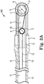
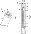
- Sliding distal component assembly 400 broadly includes tip support 58 defining a tip support cavity 57, first and second pull wires 76, 78, sliding distal component 60 and pulleys 62, 64.
- Pulleys 62, 64 have diameters that are smaller than the internal diameter of tip support 58.
- Tip support cavity 57 is configured to house the various components of sliding distal component assembly 400 and includes recess 59.
- First pulley 62 is coupled to tip support 58 proximate the distal end 54 of tip support 58 and is offset from the longitudinal axis of tip support 58 by being positioned in recess 59, as hereinbefore disclosed.
- Second pulley 64 is coupled to sliding distal component 60.
- Sliding distal component 60 is configured to be disposed within and engage the tip support 58 cavity such that is it able to translate proximally or distally relative to the longitudinal axis of the tip support 58.
- First pulley 62 is coupled to tip support 58 proximate the distal end 54 of tip support 58 such that it may rotate freely around its axis 55 but cannot translate linearly in relation to the tip support 58.
- the second pulley 64 is coupled to the distal end of the sliding distal component 60 such that it may rotate freely around its axis 56 but cannot translate linearly in relation to the tip support 58.
- a proximal end of the first pull wire 76 is coupled to an actuation mechanism operably coupled to catheter 15. From the actuation mechanism, pull wire extends distally through a catheter lumen 11 into the tip support cavity 57, where it is coupled to first fixation point 55 on sliding distal component 60. Second pull wire 56 is coupled to second fixation point 72 on tip support 58 proximate the distal end 54 thereof.
- second pull wire extends proximally and wraps around second pulley 64, reverses direction and extends distally to and wraps around first pulley 62 reversing direction and extending proximally through the tip support cavity 57 avoiding contact with the sliding distal component 60 and into the catheter lumen 11 to the actuation mechanism to which it is operably coupled.
- first pull wire 76 When the actuator mechanism is actuated by a user to a first position, tension is placed on first pull wire 76 while tension is released on second pull wire 78 causing the sliding distal component 60 to translate proximally within the tip support cavity 57.
- actuator mechanism When the actuator mechanism is moved to a second position, tension is placed on the second pull wire 78 while tension is released on the first pull wire 76 causing the sliding distal component 60 to translate distally within the tip support cavity 57.
- second pulley 64 coupled directly to sliding distal component 60 is that an even load distribution is applied to the sliding distal component 60 and this prevents the sliding distal component from pulling to one side or another.
- the invention as depicted in FIGS. 7 and 8 also enables a 2:1 movement ratio of the sliding distal component 60 as compared to the amount of translation of the proximal end of the second pull wire 78.
- the sliding distal component 60 can include an instrument (in addition to pulley 64), by way of example a needle cannula, on the distal end thereof that will be housed within the tip support cavity when the sliding distal component 60 is in a proximal position but can extend beyond the distal edge of the tip support 58 when the sliding distal component 60 translates to a distal position.
- an instrument in addition to pulley 64, by way of example a needle cannula, on the distal end thereof that will be housed within the tip support cavity when the sliding distal component 60 is in a proximal position but can extend beyond the distal edge of the tip support 58 when the sliding distal component 60 translates to a distal position.
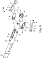
- a bioptome is a medical device that is traditionally employed to sample tissue, for example during biopsies.
- the traditional bioptome includes a 4-bar linkage system that is actuated via an elongate, relatively stiff rod.
- the bioptome in accordance with the invention has a 4-bar linkage system articulated through a pulley system by the application of tension to pull wires.
- Bioptome mechanism 900 includes upper jaw 82, lower jaw 84 and a four bar linkage system, hereinafter described.
- Upper and lower jaws 82, 84 include elongate arms 70, 72 having receiving holes 74, 75, 76 and 77, respectively.
- Sliding distal component 92 includes first and second pin portions 93, 94.
- Upper jaw includes receiving holes 76, 77 on elongate arm 70.
- Upper linkage bar 86 includes receiving hole 78 and upper linkage bar pin 79.
- Upper jaw 82 is coupled to the upper linkage bar by upper linkage bar pin 79.
- Hole 78 receives sliding distal component pin portion 93.
- Upper linkage bar pin 79 is received by hole 77 on elongate arm 70.
- Pulley pin 100 is received by upper jaw receiving hole 76.
- Lower jaw includes receiving holes 75, 75 on elongate arm 72.
- Lower linkage bar 88 includes receiving hole 81 and lower linkage bar pin 83.
- Lower jaw 84 is coupled to the lower linkage bar 88 by lower linkage bar pin 83.
- Hole 81 of lower linkage bar 88 receives sliding distal component second pin portion 94.
- Pulley pin 101 is received by lower jaw receiving hole 74.
- Distal pulley wheel 90 includes first and second pin portions 100, 101.
- First pin portion 100 is received by hole 76 in elongate arm 70.
- Second pin portion 101 is received by hole 74 in elongate arm 72.
- Pin portions 100, 101 are received by slots 110, 112 in tip support 80 which allow distal pulley wheel 90 to rotate about its axis 122.
- the four bar linkage system includes four connection points.
- the first connection point is a pinned connection at which point the upper and lower jaws 82, 84 couple with each another at a common point of rotation created by the distal pulley wheel 90.
- the upper and lower jaws 82, 84 rotate about the mating pins 100, 101 on the distal pulley wheel 90.
- the distal pulley wheel 90 rotates about pin axis 97, but is otherwise fixed in all three translation directions ( X, Y, Z in three-dimensional space) with respect to the tip support 80.
- the second connection point forming the four bar linkage system is the coupling of the upper jaw 82 with the upper linkage bar 86.
- the second connection is a pinned mating connection that is formed by upper linkage bar pin 79 and the receiving hole 77 in the upper jaw 82 elongate arm 70.
- the upper jaw 82 and upper linkage bar 86 rotate about the foregoing pined mating connection 79/77.
- the third connection point forming the four bar linkage system is the coupling of the lower jaw 84 and the lower linkage bar 88.
- the third connection is a pinned mating connection that is formed by the lower linkage bar pin 83 and the lower jaw receiving hole 75 in the elongate arm 72 of lower jaw 84.
- the lower jaw 84 and the lower linkage bar 88 rotate about the pined mating connection 83/75.
- the fourth connection point forming the four bar linkage system is at the proximal ends of the upper and lower linkage bars 86, 88.
- the fourth connection is formed by the sliding distal component 92 having first and second pin portions 93, 94 which are received by upper and lower bar receiving holes 78, 81 respectively creating a pinned connection between the two linkage bars 86, 88.
- the fourth connection point also forms a keyed mating arrangement with the tip support 80 when first and second pin portion 93, 94 are received by channels 120, 120' in tip support cavity 81 allowing the sliding distal component pin 92 to rotate in relation to its pin axis 98 and translate in the proximal or distal direction in relation to the longitudinal axis of the tip support 80.
- the sliding distal component pin 92 and fourth connection point are restricted from translation in axial directions that are orthogonal to the longitudinal axis of the tip support 80.
- the sliding distal component pin 92 translates distally the jaws 82, 84 are opened.
- the sliding distal component pin 92 translates proximally, the jaws 82, 84 are closed.
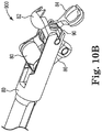
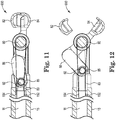
- FIG. 10A is a perspective view of the assembly shown in FIG. 9 with the jaws closed.
- FIG. 10B is a perspective view of the assembly shown in FIG. 9 with the jaws open.
- first pull wire section 152 is coupled to an actuation mechanism operably coupled to catheter 15 as hereinbefore described. From the actuation mechanism, first pull wire section extends distally through the catheter lumen into the tip support cavity 83, where it is coupled to the sliding distal component pin 92 at a fixation point 85.
- Second pull wire section 154 commences at the fixation point 85 of the sliding distal component pin 92 and extends distally where it wraps around the distal pulley wheel 90, reverses direction, and continues back proximally through the tip support cavity 83 avoiding contact with the sliding distal component pin 92 and into the catheter lumen 11 to the proximal end of the catheter 15 where it is coupled to the actuation mechanism.
Landscapes
- Health & Medical Sciences (AREA)
- Life Sciences & Earth Sciences (AREA)
- Surgery (AREA)
- Engineering & Computer Science (AREA)
- Veterinary Medicine (AREA)
- Public Health (AREA)
- General Health & Medical Sciences (AREA)
- Biomedical Technology (AREA)
- Heart & Thoracic Surgery (AREA)
- Animal Behavior & Ethology (AREA)
- Molecular Biology (AREA)
- Medical Informatics (AREA)
- Pathology (AREA)
- Nuclear Medicine, Radiotherapy & Molecular Imaging (AREA)
- Biodiversity & Conservation Biology (AREA)
- Mechanical Engineering (AREA)
- Biophysics (AREA)
- Pulmonology (AREA)
- Anesthesiology (AREA)
- Hematology (AREA)
- Surgical Instruments (AREA)
Claims (15)
- Gleitende distale Bauteilanordnung zur Verwendung in einer medizinischen Vorrichtung, die Folgendes aufweist:einen röhrenförmigen Schaft mit einem Lumen, wobei der röhrenförmige Schaft mit einem Betätigungsmechanismus gekoppelt ist, der zwischen einer ersten Stellung und einer zweiten Stellung bewegbar ist;einen Spitzenträger (80), der funktionell mit dem genannten röhrenförmigen Schaft gekoppelt ist und darin einen Spitzenträgerhohlraum (83) definiert, wobei der genannte Spitzenträgerhohlraum mit dem genannten Lumen des röhrenförmigen Schafts kontinuierlich ist;ein Rollensystem, das eine erste Rolle (90), ein gleitendes distales Bauteil (92) und wenigstens einen Zugdraht, der funktionell mit der genannten ersten Rolle und dem genannten gleitenden distalen Bauteil gekoppelt ist, beinhaltet, wobei wenigstens ein Teil des genannten Rollensystems in dem genannten Spitzenträgerhohlraum aufgenommen ist,wobei, wenn der genannte Betätigungsmechanismus in der genannten ersten Stellung ist, das gleitende distale Bauteil gestaltet ist, um proximal verschoben zu werden, und, wenn der genannte Betätigungsmechanismus in der genannten zweiten Stellung ist, das gleitende distale Bauteil gestaltet ist, um distal verschoben zu werden,wobei die genannte erste Rolle distal des genannten gleitenden distalen Bauteils positioniert ist,wobei der genannte Spitzenträgerhohlraum eine erste und eine zweite, gegenüberliegende Nut (120, 120') beinhaltet und wobei ferner der genannte gleitende distale Bauteil einen ersten Zapfenteil (93), der von dem genannten ersten Kanal (120) aufgenommen ist, und einen zweiten Zapfenteil (94), der von dem genannten zweiten Kanal (120') aufgenommen ist, beinhaltet,und wobei die genannte Anordnung ferner eine obere Verbindungswange (86), die funktionell mit dem genannten ersten Zapfenteil gekoppelt ist, und eine untere Verbindungswange (88), die funktionell mit dem genannten zweiten Zapfenteil gekoppelt ist, aufweist.
- Gleitende distale Bauteilanordnung nach Anspruch 1, wobei der genannte wenigstens eine Zugdraht ferner einen ersten Zugdrahtabschnitt (152) mit einem distalen Ende, das an einem Befestigungspunkt mit dem genannten gleitenden distalen Bauteil gekoppelt ist, und einem proximalen Ende, das mit dem genannten Betätigungsmechanismus gekoppelt ist, und einen zweiten Zugdrahtabschnitt (154) mit einem distalen Ende, das mit dem genannten Befestigungspunkt gekoppelt ist, und einem proximalen Ende, das mit dem genannten Betätigungsmechanismus gekoppelt ist, aufweist, wobei der genannte zweite Zugdrahtabschnitt funktionell mit der genannten ersten Rolle gekoppelt ist.
- Gleitende distale Bauteilanordnung nach Anspruch 2, wobei der genannte Betätigungsmechanismus so gestaltet ist, dass er in der ersten Stellung Spannung auf das proximale Ende des ersten Zugdrahtabschnitts ausübt, um zu veranlassen, dass das genannte gleitende distale Bauteil proximal verschoben wird, und ferner wobei der genannte Betätigungsmechanismus so gestaltet ist, dass er in der zweiten Stellung Spannung auf das proximale Ende des zweiten Zugdrahtabschnitts ausübt, um zu veranlassen, dass das genannte gleitende distale Bauteil distal verschoben wird.
- Gleitende distale Bauteilanordnung nach Anspruch 1, wobei der genannte Spitzenträger ein Paar einander gegenüberliegender Aussparungen (110, 112) an einem distalen Ende davon zum drehbaren Aufnehmen der genannten ersten Rolle beinhaltet.
- Gleitende distale Bauteilanordnung nach Anspruch 1, die ferner eine Ausnehmung (21) an dem genannten Spitzenträgerhohlraum zum Aufnehmen der genannten ersten Rolle aufweist.
- Gleitende distale Bauteilanordnung nach Anspruch 5, wobei die genannte erste Rolle von der Längsachse des Spitzenträgerhohlraums versetzt ist, vorzugsweise wobei das genannte gleitende distale Bauteil an einem distalen Ende davon ein Instrument beinhaltet, das sich aus dem genannten Spitzenträgerhohlraum herausbewegt, wenn das genannte gleitende distale Bauteil distal verschoben wird.
- Gleitende distale Bauteilanordnung nach Anspruch 1, wobei der genannte wenigstens eine Zugdraht einen ersten und einen zweiten, separaten Zugdraht aufweist, die jeweils ein distales und ein proximales Ende haben, wobei das proximale Ende des ersten Zugdrahts (48) funktionell mit dem Betätigungsmechanismus gekoppelt ist und das distale Ende funktionell mit einem Befestigungspunkt an dem gleitenden distalen Bauteil gekoppelt ist und wobei der zweite Zugdraht (44) funktionell mit der ersten Rolle gekoppelt ist und das distale Ende des zweiten Zugdraht mit dem Befestigungspunkt gekoppelt ist und das proximale Ende mit dem Betätigungsmechanismus gekoppelt ist.
- Gleitende distale Bauteilanordnung nach Anspruch 1, die ferner eine zweite Rolle (40) aufweist, wobei die genannte erste Rolle und zweite Rolle (40) drehbar in einer ersten und zweiten Ausnehmung (31, 31'), die in dem Spitzenträgerhohlraum gebildet sind, aufgenommen sind.
- Gleitende distale Bauteilanordnung nach Anspruch 8, wobei der genannte wenigstens eine Zugdraht einen ersten, zweiten und dritten Zugdraht aufweist, die jeweils ein distales und ein proximales Ende haben, wobei das proximale Ende von dem genannten ersten Zugdraht (48) funktionell mit dem genannten Betätigungsmechanismus gekoppelt ist und das distale Ende des genannten ersten Zugdrahts funktionell mit einem ersten Befestigungspunkt (43) an dem gleitenden distalen Bauteil gekoppelt ist, der zweite Zugdraht (44) funktionell mit der genannten ersten Rolle gekoppelt ist, wobei das distale Ende mit einem zweiten Befestigungspunkt (50) an dem gleitenden distalen Bauteil gekoppelt ist und das proximale Ende funktionell mit dem Betätigungsmechanismus gekoppelt ist, der dritte Zugdraht (46) funktionell mit der genannten zweiten Rolle gekoppelt ist, wobei das distale Ende mit einem dritten Befestigungspunkt (52) an dem gleitenden distalen Bauteil gekoppelt ist und das proximale Ende funktionell mit dem Betätigungsmechanismus gekoppelt ist.
- Gleitende distale Bauteilanordnung nach Anspruch 1, wobei die genannte erste Rolle drehbar in einer ersten Ausnehmung (59) untergebracht ist, die in dem Spitzenträgerhohlraums gebildet ist, und eine zweite Rolle (64) mit dem genannten gleitenden distalen Bauteil gekoppelt ist und drehbar von in dem Spitzenträgerhohlraum gebildeten, einander gegenüberliegenden Nuten aufgenommen ist.
- Gleitende distale Bauteilanordnung nach Anspruch 1, wobei der genannte Spitzenträgerhohlraum an einem distalen Ende davon eine erste und eine zweite Aufnahmeaussparungen (110, 112) beinhaltet.
- Gleitende distale Bauteilanordnung nach Anspruch 11, wobei die genannte erste Rolle an einander gegenüberliegenden Seiten einen ersten und zweiten Rollenzapfen (100, 101) beinhaltet, die von der genannten ersten und zweiten Aufnahmeaussparung aufgenommen sind.
- Gleitende distale Bauteilanordnung nach Anspruch 1, die ferner eine obere Backe (82) mit einem länglichen Arm (70) aufweist, der an einer ersten Position durch einen oberen Verbindungswangenzapfen (79) funktionell mit der genannten oberen Verbindungswange gekoppelt ist und an einer zweiten Position funktionell mit dem genannten ersten Rollenzapfen gekoppelt ist.
- Gleitende distale Bauteilanordnung nach Anspruch 13, die ferner eine untere Backe (84) mit einem länglichen Arm (72) aufweist, der an einer ersten Position durch einen unteren Verbindungswangenzapfen (83) funktionell mit der genannten unteren Verbindungswange gekoppelt ist und an einer zweiten Position funktionell mit dem genannten zweiten Rollenzapfen gekoppelt ist.
- Gleitende distale Bauteilanordnung nach Anspruch 14, wobei die genannte obere und untere Backe durch die genannte erste Rolle an einem gemeinsamen Drehpunkt funktionell miteinander gekoppelt sind oder wobei die genannte obere und untere Backe in der geschlossenen Stellung sind, wenn das gleitende distale Bauteil gestaltet ist, um proximal verschoben zu werden, oder wobei die genannte obere und untere Backe in der offenen Stellung sind, wenn das gleitende distale Bauteil gestaltet ist, um distal verschoben zu werden.
Applications Claiming Priority (2)
| Application Number | Priority Date | Filing Date | Title |
|---|---|---|---|
| US201562247525P | 2015-10-28 | 2015-10-28 | |
| PCT/US2016/059299 WO2017075336A1 (en) | 2015-10-28 | 2016-10-28 | Sliding distal component assembly |
Publications (3)
| Publication Number | Publication Date |
|---|---|
| EP3367916A1 EP3367916A1 (de) | 2018-09-05 |
| EP3367916A4 EP3367916A4 (de) | 2019-06-05 |
| EP3367916B1 true EP3367916B1 (de) | 2021-02-17 |
Family
ID=58631118
Family Applications (1)
| Application Number | Title | Priority Date | Filing Date |
|---|---|---|---|
| EP16860867.7A Active EP3367916B1 (de) | 2015-10-28 | 2016-10-28 | Gleitende distale komponentenanordnung |
Country Status (3)
| Country | Link |
|---|---|
| US (1) | US10751510B2 (de) |
| EP (1) | EP3367916B1 (de) |
| WO (1) | WO2017075336A1 (de) |
Families Citing this family (4)
| Publication number | Priority date | Publication date | Assignee | Title |
|---|---|---|---|---|
| US11207499B2 (en) * | 2017-10-20 | 2021-12-28 | Edwards Lifesciences Corporation | Steerable catheter |
| US11553939B2 (en) | 2018-10-31 | 2023-01-17 | Cilag Gmbh International | Surgical instruments with a retention feature that retains a cutting element |
| US20200138507A1 (en) * | 2018-11-02 | 2020-05-07 | Ethicon Llc | Distal closure mechanism for surgical instruments |
| US11406442B2 (en) | 2018-11-05 | 2022-08-09 | Cilag Gmbh International | Articulate wrist with flexible central member |
Family Cites Families (8)
| Publication number | Priority date | Publication date | Assignee | Title |
|---|---|---|---|---|
| US6840938B1 (en) * | 2000-12-29 | 2005-01-11 | Intuitive Surgical, Inc. | Bipolar cauterizing instrument |
| US7824401B2 (en) * | 2004-10-08 | 2010-11-02 | Intuitive Surgical Operations, Inc. | Robotic tool with wristed monopolar electrosurgical end effectors |
| WO2010126129A1 (ja) | 2009-04-30 | 2010-11-04 | テルモ株式会社 | 医療用マニピュレータ |
| US8333780B1 (en) | 2009-06-05 | 2012-12-18 | Okay Industries, Inc. | Surgical tool and method of operation |
| WO2013090558A1 (en) | 2011-12-15 | 2013-06-20 | Imricor Medical Systems, Inc. | Mri compatible handle and steerable sheath |
| EP2793989A1 (de) * | 2011-12-22 | 2014-10-29 | Boston Scientific Scimed, Inc. | Griff mit nabe mit rotierendem infusionseitenport |
| JP5684433B2 (ja) * | 2013-01-18 | 2015-03-11 | オリンパスメディカルシステムズ株式会社 | 処置具 |
| EP3578119B1 (de) * | 2013-12-11 | 2021-03-17 | Covidien LP | Handgelenk- und backenanordnungen für chirurgische robotersysteme |
-
2016
- 2016-10-28 EP EP16860867.7A patent/EP3367916B1/de active Active
- 2016-10-28 US US15/771,303 patent/US10751510B2/en active Active
- 2016-10-28 WO PCT/US2016/059299 patent/WO2017075336A1/en not_active Ceased
Non-Patent Citations (1)
| Title |
|---|
| None * |
Also Published As
| Publication number | Publication date |
|---|---|
| US20180311471A1 (en) | 2018-11-01 |
| US10751510B2 (en) | 2020-08-25 |
| EP3367916A4 (de) | 2019-06-05 |
| EP3367916A1 (de) | 2018-09-05 |
| WO2017075336A1 (en) | 2017-05-04 |
Similar Documents
| Publication | Publication Date | Title |
|---|---|---|
| CA2894763C (en) | Mri compatible handle and steerable sheath | |
| EP2931111B1 (de) | Mrt-kompatibler griff und lenkbare schleuse | |
| US10238448B2 (en) | Surgical devices and mechanisms | |
| US9907570B2 (en) | Steerable medical devices | |
| JP2004532074A (ja) | 医療用カテーテル用ハンドルの設計 | |
| JP5201755B2 (ja) | 操舵可能なスタイレット | |
| EP3367916B1 (de) | Gleitende distale komponentenanordnung | |
| JP2007530174A (ja) | 血管用ガイドワイヤシステム | |
| US20150045696A1 (en) | Steerable dilator | |
| US20160008575A1 (en) | Slidable valve adaptor for steerable sheath | |
| WO2016176292A1 (en) | Mr compatible puncture catheter | |
| WO2017155867A1 (en) | Mri compatible handle with steerable sheath and neutral position indicator | |
| WO2023142428A1 (zh) | 一种可双向弯曲的花键篮消融导管 | |
| WO2018037594A1 (ja) | 医療機器用ハンドルおよび医療機器 | |
| US20250082399A1 (en) | Magnetically coupled ablation components | |
| US11918762B2 (en) | Reduced actuation force electrophysiology catheter handle | |
| EP3291869A1 (de) | Verschiebbarer ventiladapter für lenkbare hülle | |
| JP2004536628A (ja) | 入れ子式端部電極カテーテル | |
| HK1211824B (en) | Mri compatible handle and steerable sheath |
Legal Events
| Date | Code | Title | Description |
|---|---|---|---|
| STAA | Information on the status of an ep patent application or granted ep patent |
Free format text: STATUS: THE INTERNATIONAL PUBLICATION HAS BEEN MADE |
|
| PUAI | Public reference made under article 153(3) epc to a published international application that has entered the european phase |
Free format text: ORIGINAL CODE: 0009012 |
|
| STAA | Information on the status of an ep patent application or granted ep patent |
Free format text: STATUS: REQUEST FOR EXAMINATION WAS MADE |
|
| 17P | Request for examination filed |
Effective date: 20180503 |
|
| AK | Designated contracting states |
Kind code of ref document: A1 Designated state(s): AL AT BE BG CH CY CZ DE DK EE ES FI FR GB GR HR HU IE IS IT LI LT LU LV MC MK MT NL NO PL PT RO RS SE SI SK SM TR |
|
| AX | Request for extension of the european patent |
Extension state: BA ME |
|
| DAV | Request for validation of the european patent (deleted) | ||
| DAX | Request for extension of the european patent (deleted) | ||
| A4 | Supplementary search report drawn up and despatched |
Effective date: 20190506 |
|
| RIC1 | Information provided on ipc code assigned before grant |
Ipc: A61B 10/06 20060101AFI20190429BHEP Ipc: A61M 25/092 20060101ALI20190429BHEP |
|
| GRAP | Despatch of communication of intention to grant a patent |
Free format text: ORIGINAL CODE: EPIDOSNIGR1 |
|
| STAA | Information on the status of an ep patent application or granted ep patent |
Free format text: STATUS: GRANT OF PATENT IS INTENDED |
|
| INTG | Intention to grant announced |
Effective date: 20200910 |
|
| GRAS | Grant fee paid |
Free format text: ORIGINAL CODE: EPIDOSNIGR3 |
|
| GRAA | (expected) grant |
Free format text: ORIGINAL CODE: 0009210 |
|
| STAA | Information on the status of an ep patent application or granted ep patent |
Free format text: STATUS: THE PATENT HAS BEEN GRANTED |
|
| AK | Designated contracting states |
Kind code of ref document: B1 Designated state(s): AL AT BE BG CH CY CZ DE DK EE ES FI FR GB GR HR HU IE IS IT LI LT LU LV MC MK MT NL NO PL PT RO RS SE SI SK SM TR |
|
| REG | Reference to a national code |
Ref country code: GB Ref legal event code: FG4D |
|
| REG | Reference to a national code |
Ref country code: CH Ref legal event code: EP |
|
| REG | Reference to a national code |
Ref country code: DE Ref legal event code: R096 Ref document number: 602016052819 Country of ref document: DE |
|
| REG | Reference to a national code |
Ref country code: AT Ref legal event code: REF Ref document number: 1360411 Country of ref document: AT Kind code of ref document: T Effective date: 20210315 |
|
| REG | Reference to a national code |
Ref country code: NL Ref legal event code: FP Ref country code: IE Ref legal event code: FG4D |
|
| REG | Reference to a national code |
Ref country code: LT Ref legal event code: MG9D |
|
| PG25 | Lapsed in a contracting state [announced via postgrant information from national office to epo] |
Ref country code: GR Free format text: LAPSE BECAUSE OF FAILURE TO SUBMIT A TRANSLATION OF THE DESCRIPTION OR TO PAY THE FEE WITHIN THE PRESCRIBED TIME-LIMIT Effective date: 20210518 Ref country code: FI Free format text: LAPSE BECAUSE OF FAILURE TO SUBMIT A TRANSLATION OF THE DESCRIPTION OR TO PAY THE FEE WITHIN THE PRESCRIBED TIME-LIMIT Effective date: 20210217 Ref country code: HR Free format text: LAPSE BECAUSE OF FAILURE TO SUBMIT A TRANSLATION OF THE DESCRIPTION OR TO PAY THE FEE WITHIN THE PRESCRIBED TIME-LIMIT Effective date: 20210217 Ref country code: NO Free format text: LAPSE BECAUSE OF FAILURE TO SUBMIT A TRANSLATION OF THE DESCRIPTION OR TO PAY THE FEE WITHIN THE PRESCRIBED TIME-LIMIT Effective date: 20210517 Ref country code: PT Free format text: LAPSE BECAUSE OF FAILURE TO SUBMIT A TRANSLATION OF THE DESCRIPTION OR TO PAY THE FEE WITHIN THE PRESCRIBED TIME-LIMIT Effective date: 20210617 Ref country code: BG Free format text: LAPSE BECAUSE OF FAILURE TO SUBMIT A TRANSLATION OF THE DESCRIPTION OR TO PAY THE FEE WITHIN THE PRESCRIBED TIME-LIMIT Effective date: 20210517 Ref country code: LT Free format text: LAPSE BECAUSE OF FAILURE TO SUBMIT A TRANSLATION OF THE DESCRIPTION OR TO PAY THE FEE WITHIN THE PRESCRIBED TIME-LIMIT Effective date: 20210217 |
|
| REG | Reference to a national code |
Ref country code: AT Ref legal event code: MK05 Ref document number: 1360411 Country of ref document: AT Kind code of ref document: T Effective date: 20210217 |
|
| PG25 | Lapsed in a contracting state [announced via postgrant information from national office to epo] |
Ref country code: PL Free format text: LAPSE BECAUSE OF FAILURE TO SUBMIT A TRANSLATION OF THE DESCRIPTION OR TO PAY THE FEE WITHIN THE PRESCRIBED TIME-LIMIT Effective date: 20210217 Ref country code: LV Free format text: LAPSE BECAUSE OF FAILURE TO SUBMIT A TRANSLATION OF THE DESCRIPTION OR TO PAY THE FEE WITHIN THE PRESCRIBED TIME-LIMIT Effective date: 20210217 Ref country code: RS Free format text: LAPSE BECAUSE OF FAILURE TO SUBMIT A TRANSLATION OF THE DESCRIPTION OR TO PAY THE FEE WITHIN THE PRESCRIBED TIME-LIMIT Effective date: 20210217 Ref country code: SE Free format text: LAPSE BECAUSE OF FAILURE TO SUBMIT A TRANSLATION OF THE DESCRIPTION OR TO PAY THE FEE WITHIN THE PRESCRIBED TIME-LIMIT Effective date: 20210217 |
|
| PG25 | Lapsed in a contracting state [announced via postgrant information from national office to epo] |
Ref country code: IS Free format text: LAPSE BECAUSE OF FAILURE TO SUBMIT A TRANSLATION OF THE DESCRIPTION OR TO PAY THE FEE WITHIN THE PRESCRIBED TIME-LIMIT Effective date: 20210617 |
|
| PG25 | Lapsed in a contracting state [announced via postgrant information from national office to epo] |
Ref country code: CZ Free format text: LAPSE BECAUSE OF FAILURE TO SUBMIT A TRANSLATION OF THE DESCRIPTION OR TO PAY THE FEE WITHIN THE PRESCRIBED TIME-LIMIT Effective date: 20210217 Ref country code: EE Free format text: LAPSE BECAUSE OF FAILURE TO SUBMIT A TRANSLATION OF THE DESCRIPTION OR TO PAY THE FEE WITHIN THE PRESCRIBED TIME-LIMIT Effective date: 20210217 Ref country code: SM Free format text: LAPSE BECAUSE OF FAILURE TO SUBMIT A TRANSLATION OF THE DESCRIPTION OR TO PAY THE FEE WITHIN THE PRESCRIBED TIME-LIMIT Effective date: 20210217 Ref country code: AT Free format text: LAPSE BECAUSE OF FAILURE TO SUBMIT A TRANSLATION OF THE DESCRIPTION OR TO PAY THE FEE WITHIN THE PRESCRIBED TIME-LIMIT Effective date: 20210217 |
|
| REG | Reference to a national code |
Ref country code: DE Ref legal event code: R097 Ref document number: 602016052819 Country of ref document: DE |
|
| PG25 | Lapsed in a contracting state [announced via postgrant information from national office to epo] |
Ref country code: DK Free format text: LAPSE BECAUSE OF FAILURE TO SUBMIT A TRANSLATION OF THE DESCRIPTION OR TO PAY THE FEE WITHIN THE PRESCRIBED TIME-LIMIT Effective date: 20210217 Ref country code: RO Free format text: LAPSE BECAUSE OF FAILURE TO SUBMIT A TRANSLATION OF THE DESCRIPTION OR TO PAY THE FEE WITHIN THE PRESCRIBED TIME-LIMIT Effective date: 20210217 Ref country code: SK Free format text: LAPSE BECAUSE OF FAILURE TO SUBMIT A TRANSLATION OF THE DESCRIPTION OR TO PAY THE FEE WITHIN THE PRESCRIBED TIME-LIMIT Effective date: 20210217 |
|
| PLBE | No opposition filed within time limit |
Free format text: ORIGINAL CODE: 0009261 |
|
| STAA | Information on the status of an ep patent application or granted ep patent |
Free format text: STATUS: NO OPPOSITION FILED WITHIN TIME LIMIT |
|
| 26N | No opposition filed |
Effective date: 20211118 |
|
| PG25 | Lapsed in a contracting state [announced via postgrant information from national office to epo] |
Ref country code: ES Free format text: LAPSE BECAUSE OF FAILURE TO SUBMIT A TRANSLATION OF THE DESCRIPTION OR TO PAY THE FEE WITHIN THE PRESCRIBED TIME-LIMIT Effective date: 20210217 Ref country code: AL Free format text: LAPSE BECAUSE OF FAILURE TO SUBMIT A TRANSLATION OF THE DESCRIPTION OR TO PAY THE FEE WITHIN THE PRESCRIBED TIME-LIMIT Effective date: 20210217 |
|
| PG25 | Lapsed in a contracting state [announced via postgrant information from national office to epo] |
Ref country code: SI Free format text: LAPSE BECAUSE OF FAILURE TO SUBMIT A TRANSLATION OF THE DESCRIPTION OR TO PAY THE FEE WITHIN THE PRESCRIBED TIME-LIMIT Effective date: 20210217 |
|
| PG25 | Lapsed in a contracting state [announced via postgrant information from national office to epo] |
Ref country code: IT Free format text: LAPSE BECAUSE OF FAILURE TO SUBMIT A TRANSLATION OF THE DESCRIPTION OR TO PAY THE FEE WITHIN THE PRESCRIBED TIME-LIMIT Effective date: 20210217 |
|
| REG | Reference to a national code |
Ref country code: CH Ref legal event code: PL |
|
| PG25 | Lapsed in a contracting state [announced via postgrant information from national office to epo] |
Ref country code: IS Free format text: LAPSE BECAUSE OF FAILURE TO SUBMIT A TRANSLATION OF THE DESCRIPTION OR TO PAY THE FEE WITHIN THE PRESCRIBED TIME-LIMIT Effective date: 20210617 |
|
| REG | Reference to a national code |
Ref country code: BE Ref legal event code: MM Effective date: 20211031 |
|
| PG25 | Lapsed in a contracting state [announced via postgrant information from national office to epo] |
Ref country code: MC Free format text: LAPSE BECAUSE OF FAILURE TO SUBMIT A TRANSLATION OF THE DESCRIPTION OR TO PAY THE FEE WITHIN THE PRESCRIBED TIME-LIMIT Effective date: 20210217 |
|
| PG25 | Lapsed in a contracting state [announced via postgrant information from national office to epo] |
Ref country code: LU Free format text: LAPSE BECAUSE OF NON-PAYMENT OF DUE FEES Effective date: 20211028 Ref country code: BE Free format text: LAPSE BECAUSE OF NON-PAYMENT OF DUE FEES Effective date: 20211031 |
|
| PG25 | Lapsed in a contracting state [announced via postgrant information from national office to epo] |
Ref country code: LI Free format text: LAPSE BECAUSE OF NON-PAYMENT OF DUE FEES Effective date: 20211031 Ref country code: CH Free format text: LAPSE BECAUSE OF NON-PAYMENT OF DUE FEES Effective date: 20211031 |
|
| PG25 | Lapsed in a contracting state [announced via postgrant information from national office to epo] |
Ref country code: IE Free format text: LAPSE BECAUSE OF NON-PAYMENT OF DUE FEES Effective date: 20211028 |
|
| PG25 | Lapsed in a contracting state [announced via postgrant information from national office to epo] |
Ref country code: HU Free format text: LAPSE BECAUSE OF FAILURE TO SUBMIT A TRANSLATION OF THE DESCRIPTION OR TO PAY THE FEE WITHIN THE PRESCRIBED TIME-LIMIT; INVALID AB INITIO Effective date: 20161028 |
|
| PG25 | Lapsed in a contracting state [announced via postgrant information from national office to epo] |
Ref country code: CY Free format text: LAPSE BECAUSE OF FAILURE TO SUBMIT A TRANSLATION OF THE DESCRIPTION OR TO PAY THE FEE WITHIN THE PRESCRIBED TIME-LIMIT Effective date: 20210217 |
|
| P01 | Opt-out of the competence of the unified patent court (upc) registered |
Effective date: 20230905 |
|
| PG25 | Lapsed in a contracting state [announced via postgrant information from national office to epo] |
Ref country code: MK Free format text: LAPSE BECAUSE OF FAILURE TO SUBMIT A TRANSLATION OF THE DESCRIPTION OR TO PAY THE FEE WITHIN THE PRESCRIBED TIME-LIMIT Effective date: 20210217 |
|
| PG25 | Lapsed in a contracting state [announced via postgrant information from national office to epo] |
Ref country code: TR Free format text: LAPSE BECAUSE OF FAILURE TO SUBMIT A TRANSLATION OF THE DESCRIPTION OR TO PAY THE FEE WITHIN THE PRESCRIBED TIME-LIMIT Effective date: 20210217 |
|
| PG25 | Lapsed in a contracting state [announced via postgrant information from national office to epo] |
Ref country code: MT Free format text: LAPSE BECAUSE OF FAILURE TO SUBMIT A TRANSLATION OF THE DESCRIPTION OR TO PAY THE FEE WITHIN THE PRESCRIBED TIME-LIMIT Effective date: 20210217 |
|
| PGFP | Annual fee paid to national office [announced via postgrant information from national office to epo] |
Ref country code: DE Payment date: 20241021 Year of fee payment: 9 |
|
| PGFP | Annual fee paid to national office [announced via postgrant information from national office to epo] |
Ref country code: GB Payment date: 20241025 Year of fee payment: 9 |
|
| PGFP | Annual fee paid to national office [announced via postgrant information from national office to epo] |
Ref country code: FR Payment date: 20241030 Year of fee payment: 9 |
|
| PGFP | Annual fee paid to national office [announced via postgrant information from national office to epo] |
Ref country code: NL Payment date: 20251021 Year of fee payment: 10 |