EP3367511A1 - Connection module for an automotive vehicle - Google Patents
Connection module for an automotive vehicle Download PDFInfo
- Publication number
- EP3367511A1 EP3367511A1 EP17382088.7A EP17382088A EP3367511A1 EP 3367511 A1 EP3367511 A1 EP 3367511A1 EP 17382088 A EP17382088 A EP 17382088A EP 3367511 A1 EP3367511 A1 EP 3367511A1
- Authority
- EP
- European Patent Office
- Prior art keywords
- pcb
- edge
- connector
- connection module
- electrical connection
- Prior art date
- Legal status (The legal status is an assumption and is not a legal conclusion. Google has not performed a legal analysis and makes no representation as to the accuracy of the status listed.)
- Withdrawn
Links
Images
Classifications
-
- H—ELECTRICITY
- H01—ELECTRIC ELEMENTS
- H01R—ELECTRICALLY-CONDUCTIVE CONNECTIONS; STRUCTURAL ASSOCIATIONS OF A PLURALITY OF MUTUALLY-INSULATED ELECTRICAL CONNECTING ELEMENTS; COUPLING DEVICES; CURRENT COLLECTORS
- H01R12/00—Structural associations of a plurality of mutually-insulated electrical connecting elements, specially adapted for printed circuits, e.g. printed circuit boards [PCB], flat or ribbon cables, or like generally planar structures, e.g. terminal strips, terminal blocks; Coupling devices specially adapted for printed circuits, flat or ribbon cables, or like generally planar structures; Terminals specially adapted for contact with, or insertion into, printed circuits, flat or ribbon cables, or like generally planar structures
- H01R12/70—Coupling devices
- H01R12/71—Coupling devices for rigid printing circuits or like structures
- H01R12/72—Coupling devices for rigid printing circuits or like structures coupling with the edge of the rigid printed circuits or like structures
- H01R12/721—Coupling devices for rigid printing circuits or like structures coupling with the edge of the rigid printed circuits or like structures cooperating directly with the edge of the rigid printed circuits
-
- H—ELECTRICITY
- H01—ELECTRIC ELEMENTS
- H01R—ELECTRICALLY-CONDUCTIVE CONNECTIONS; STRUCTURAL ASSOCIATIONS OF A PLURALITY OF MUTUALLY-INSULATED ELECTRICAL CONNECTING ELEMENTS; COUPLING DEVICES; CURRENT COLLECTORS
- H01R13/00—Details of coupling devices of the kinds covered by groups H01R12/70 or H01R24/00 - H01R33/00
- H01R13/62—Means for facilitating engagement or disengagement of coupling parts or for holding them in engagement
- H01R13/627—Snap or like fastening
- H01R13/6271—Latching means integral with the housing
- H01R13/6272—Latching means integral with the housing comprising a single latching arm
-
- H—ELECTRICITY
- H05—ELECTRIC TECHNIQUES NOT OTHERWISE PROVIDED FOR
- H05K—PRINTED CIRCUITS; CASINGS OR CONSTRUCTIONAL DETAILS OF ELECTRIC APPARATUS; MANUFACTURE OF ASSEMBLAGES OF ELECTRICAL COMPONENTS
- H05K3/00—Apparatus or processes for manufacturing printed circuits
- H05K3/30—Assembling printed circuits with electric components, e.g. with resistor
- H05K3/32—Assembling printed circuits with electric components, e.g. with resistor electrically connecting electric components or wires to printed circuits
- H05K3/325—Assembling printed circuits with electric components, e.g. with resistor electrically connecting electric components or wires to printed circuits by abutting or pinching, i.e. without alloying process; mechanical auxiliary parts therefor
- H05K3/326—Assembling printed circuits with electric components, e.g. with resistor electrically connecting electric components or wires to printed circuits by abutting or pinching, i.e. without alloying process; mechanical auxiliary parts therefor the printed circuit having integral resilient or deformable parts, e.g. tabs or parts of flexible circuits
-
- H—ELECTRICITY
- H05—ELECTRIC TECHNIQUES NOT OTHERWISE PROVIDED FOR
- H05K—PRINTED CIRCUITS; CASINGS OR CONSTRUCTIONAL DETAILS OF ELECTRIC APPARATUS; MANUFACTURE OF ASSEMBLAGES OF ELECTRICAL COMPONENTS
- H05K3/00—Apparatus or processes for manufacturing printed circuits
- H05K3/40—Forming printed elements for providing electric connections to or between printed circuits
- H05K3/403—Edge contacts; Windows or holes in the substrate having plural connections on the walls thereof
-
- F—MECHANICAL ENGINEERING; LIGHTING; HEATING; WEAPONS; BLASTING
- F21—LIGHTING
- F21K—NON-ELECTRIC LIGHT SOURCES USING LUMINESCENCE; LIGHT SOURCES USING ELECTROCHEMILUMINESCENCE; LIGHT SOURCES USING CHARGES OF COMBUSTIBLE MATERIAL; LIGHT SOURCES USING SEMICONDUCTOR DEVICES AS LIGHT-GENERATING ELEMENTS; LIGHT SOURCES NOT OTHERWISE PROVIDED FOR
- F21K9/00—Light sources using semiconductor devices as light-generating elements, e.g. using light-emitting diodes [LED] or lasers
- F21K9/20—Light sources comprising attachment means
-
- H—ELECTRICITY
- H01—ELECTRIC ELEMENTS
- H01R—ELECTRICALLY-CONDUCTIVE CONNECTIONS; STRUCTURAL ASSOCIATIONS OF A PLURALITY OF MUTUALLY-INSULATED ELECTRICAL CONNECTING ELEMENTS; COUPLING DEVICES; CURRENT COLLECTORS
- H01R12/00—Structural associations of a plurality of mutually-insulated electrical connecting elements, specially adapted for printed circuits, e.g. printed circuit boards [PCB], flat or ribbon cables, or like generally planar structures, e.g. terminal strips, terminal blocks; Coupling devices specially adapted for printed circuits, flat or ribbon cables, or like generally planar structures; Terminals specially adapted for contact with, or insertion into, printed circuits, flat or ribbon cables, or like generally planar structures
- H01R12/70—Coupling devices
- H01R12/77—Coupling devices for flexible printed circuits, flat or ribbon cables or like structures
- H01R12/79—Coupling devices for flexible printed circuits, flat or ribbon cables or like structures connecting to rigid printed circuits or like structures
-
- H—ELECTRICITY
- H01—ELECTRIC ELEMENTS
- H01R—ELECTRICALLY-CONDUCTIVE CONNECTIONS; STRUCTURAL ASSOCIATIONS OF A PLURALITY OF MUTUALLY-INSULATED ELECTRICAL CONNECTING ELEMENTS; COUPLING DEVICES; CURRENT COLLECTORS
- H01R2201/00—Connectors or connections adapted for particular applications
- H01R2201/26—Connectors or connections adapted for particular applications for vehicles
-
- H—ELECTRICITY
- H05—ELECTRIC TECHNIQUES NOT OTHERWISE PROVIDED FOR
- H05K—PRINTED CIRCUITS; CASINGS OR CONSTRUCTIONAL DETAILS OF ELECTRIC APPARATUS; MANUFACTURE OF ASSEMBLAGES OF ELECTRICAL COMPONENTS
- H05K1/00—Printed circuits
- H05K1/02—Details
- H05K1/11—Printed elements for providing electric connections to or between printed circuits
- H05K1/117—Pads along the edge of rigid circuit boards, e.g. for pluggable connectors
-
- H—ELECTRICITY
- H05—ELECTRIC TECHNIQUES NOT OTHERWISE PROVIDED FOR
- H05K—PRINTED CIRCUITS; CASINGS OR CONSTRUCTIONAL DETAILS OF ELECTRIC APPARATUS; MANUFACTURE OF ASSEMBLAGES OF ELECTRICAL COMPONENTS
- H05K2201/00—Indexing scheme relating to printed circuits covered by H05K1/00
- H05K2201/09—Shape and layout
- H05K2201/09145—Edge details
-
- H—ELECTRICITY
- H05—ELECTRIC TECHNIQUES NOT OTHERWISE PROVIDED FOR
- H05K—PRINTED CIRCUITS; CASINGS OR CONSTRUCTIONAL DETAILS OF ELECTRIC APPARATUS; MANUFACTURE OF ASSEMBLAGES OF ELECTRICAL COMPONENTS
- H05K2201/00—Indexing scheme relating to printed circuits covered by H05K1/00
- H05K2201/10—Details of components or other objects attached to or integrated in a printed circuit board
- H05K2201/10007—Types of components
- H05K2201/10189—Non-printed connector
Definitions
- an electrical connection module for an automotive vehicle comprises a printed circuit board, PCB, and an edge connector for connecting a wire harness to said PCB, into which edge connector an edge of the PCB is insertable.
- the PCB comprises retention means, which are formed thereon, and which are adapted to retain said edge connector, if the edge of the PCB is seated therein.
- the PCB may preferably comprise an electronic circuit having at least one light source, and the edge connector may be used to connect said PCT to a power supply through a wire harness.
Abstract
Description
- It is known to use several types of electrical connectors, including plug and socket-type devices, to electrically connect an electronic circuit, which is implemented on a printed circuit board, PCB, to a remote device. The remote device may for example be a power supply, which supplies electrical current to the electronic circuit via a harness having at least one wire terminating in the electrical connector. The electrical connector interfaces with the electronic circuit on the PCB.
- A specific type of connector known in the art is the "cardedge" connector. The connector features a body for connecting the wires of a wire harness. A pair of opposing jaws extends from the body and is configured to receive a printed circuit board supporting an electronic circuit therebetween. The jaws comprise electrical contacts, which are electrically connected to the wire harness through the connector's body. The arrangement is such that the electrical contacts located on the jaws establish contact with a corresponding electrically conductive area on the PCB that is pinched between the jaws.
- However, if the PCB is not properly inserted between the jaws of the cardedge connector, or, if either or both of the PCB and the connector are subject to vibrations or shocks during use, the connector may become disconnected from the PCB. Such an incident may only be attended to by manual intervention. This situation is particularly critical when the cardegdge connector, which has the benefit of having a small footprint, is used in a lighting module for an automotive car. Typically, physical space is a major constraint in such an environment, so that the use of a cardedge-type connector is interesting. However, an automotive vehicle is subject to vibrations or shocks, so that it becomes likely for the connector to disconnect during use. Moreover, the manual intervention required to fix the connection is often work-intensive as well as costly, because many components of the automotive vehicle may have to be removed before the connector and PCB become accessible - if they are accessible at all.
- It has been suggested to mount the connector with its rear face abutted against a wall, thereby decreasing the likelihood of disconnection from the PCB to which it is connected. This imposes severe design and placement constraints on the PCB, which has to be located in close proximity to a wall of a device.
- It is an objective of the present invention to alleviate at least some of the drawbacks found in the prior art.
- In accordance with a first aspect of the invention, an electrical connection module for an automotive vehicle is provided. The module comprises a printed circuit board, PCB, and an edge connector for connecting a wire harness to said PCB, into which edge connector an edge of the PCB is insertable. The PCB comprises retention means, which are formed thereon, and which are adapted to retain said edge connector, if the edge of the PCB is seated therein.
- The retention means are advantageously integrally formed on the PCB. As variants, the retention means can be overmolded and/or clipped on the PCB.
- The edge of the PCB insertable into the edge connector may preferably form a recessed edge portion.
- Preferably, the retention means may comprise at least one arm, preferably a pair of arms, extending from the PCB in the direction of insertion of the edge of the PCB into the edge connector, the arm or each arm comprising a hand configured for grasping a back side of said edge connector.
- The arm(s) may preferably be configured as flexible clips.
- The retention means may preferably comprise a resilient flexible portion which extends in a direction that is generally perpendicular to the direction of insertion of the edge of the PCB into the edge connector. The resilient flexible portion is preferably integrally formed on the PCB.
- The resilient flexible portion may preferably be a rib configured for being bent out of the PCB's plane when inserting the edge of the PCB into the edge connector.
- The rib or arms may be formed by cutting out at least one neighbouring region from the PCB.
- Preferably, the resilient flexible portion may contact a back side of the edge connector, when the PCB is seated therein.
- The retention means may preferably be formed in a reinforced region of the PCB. The reinforced region may locally comprise a board thickness that is larger than the overall board thickness of the PCB.
- Preferably, the retention means may be formed so that they are flush with the edge of the PCB.
- The edge connector may preferably comprise a main body for connecting a wire harness, and a pair of opposing jaws for receiving the edge of the PCB therebetween.
- The PCB may preferably comprise an electronic circuit having at least one light source, and the edge connector may be used to connect said PCT to a power supply through a wire harness.
- Preferably, the light source is a light emitting diode, LED, or a Laser diode.
- In accordance with a further aspect of the invention a lighting module for an automotive vehicle is provided. The lighting module comprises a PCB that supports an electronic circuit having at least one light source. The module further comprises a wire harness connecting said electronic circuit to an electric current source by means of an edge connector. The PCB and the edge connector are part of an electrical connection module according to the invention.
- The invention allows securing a cardedge-type connector to a printed circuit board, PCB, while significantly reducing the risk of disconnection, even if the assembly is subject to vibrations and/or shocks after the connection has been established. By using specific holding features or retention means directly embedded in the PCB itself, there is no need to use a third part to secure the connection. This feature reduces the overall footprint of the connection module, and reduces production costs. Obviously, the maintenance time is reduced as the risk of disconnection is lowered. The disconnection-proof connection module further alleviates the constraints for mounting a PCB-cardedge module. Specifically, the module does not have to be mounted in proximity of a wall of the containing device as in prior art solutions. The above advantages render the connection module according to the invention particularly appealing for the automotive lighting industry, where connected modules are subject to vibrations, where physical space is a scarce resource, and where maintenance interventions are difficult to achieve.
- Several embodiments of the present invention are illustrated by way of figures, which do not limit the scope of the invention, wherein:
-
figure 1 is a perspective view illustration of an electrical connection module according to a preferred embodiment of the invention, wherein the PCB is not seated in the connector; -
figure 2 is a perspective view illustration of an electrical connection module according to a preferred embodiment of the invention, wherein the PCB is seated in the connector; -
figure 3 illustrates the features of a PCB according to a preferred embodiment of the invention; -
figure 4 shows the PCB offigure 3 , seated in a connector in accordance with a preferred embodiment of the invention; -
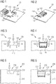
figure 5 illustrates the features of a PCB according to a preferred embodiment of the invention; -
figure 6 shows the PCB offigure 5 , seated in a connector in accordance with a preferred embodiment of the invention; -
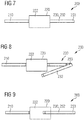
figure 7, 8 and 9 are views depicting the edge of PCB and back side of a connector in accordance with a preferred embodiment of the invention, in different configurations. - This section describes the invention in further detail based on preferred embodiments and on the figures. It should be noted that features described for a specific embodiment described herein may be combined with the features of other embodiments unless the contrary is explicitly mentioned. Similar features are referenced with similar numbers across multiple embodiments, wherein the reference numbers are, unless otherwise stated, incremented by one hundred when moving to the next embodiment. For example,
reference numbers - It should be understood that the detailed description of specific preferred embodiments is given by way of illustration only, since various changes and modifications within the scope of the invention will be apparent to the person skilled in the art. The scope of protection is defined by the following set of claims.
- It is known to produce printed circuit boards, PCB, from a synthetic resin and to print or deposit electrically conductive traces thereon, which interconnect surface mounted devices or components of the electronic circuit to provide a specific function. Processes for producing a PCB or for creating such conductive traces thereon will not be described in the context of the present invention.
-
Figure 1 show anelectrical connection module 100 in accordance with a first embodiment of the invention. Themodule 100 comprises aPCB 110 and anedge connector 120. Theconnector 120 is used for connecting a wire harness, which is not shown, to the PCB. Anedge 112 of the PCB is insertable into theconnector 120, which possesses a pair of jaws for receiving the PCB therebetween. As shown onfigure 1 , the connector comprises a main body that may be perceived by the series of round openings therein, in which conducting wires of a wire harness may be received and fixed. The pair of opposing jaws extends from the main body in the direction of thePCB 110. The connector comprises electrical connections which allow establishing an electrical contact between the wire-receiving part and the PCB-contacting part thereof. The PCB comprises retention means 130, integrally formed thereon, which are adapted to retain the edge connector, when the PCB is seated therein. Infigure 1 , thearms arms arms hands connector 120 is pushed towards the PCB, thehands arms hands backside 122 of theedge connector 120, as illustrated infigure 2 , thereby retaining it and keeping it from moving away from thePCB 110. The hands and arms effectively implement a clipping mechanism. Other shapes of arms and/or hands than those shown may be implemented by the skilled person without leaving the scope of the present invention, for as long as they mechanically lock theconnector 120 in place, once it is seated in said cut-out recess of the PCB. -
Figures 3 and 4 provide bird's eye views from the PCB shown infigures 1 and 2 respectively. The retention means 130, includingarms hands Figure 4 , thePCB 110 is seated between the jaws of theedge connector 120, theback side 122 of which is held by thehands connector 120 may not freely move in the direction opposite to direction A, thereby achieving the effect of the invention. - A second embodiment of the
electrical connection module 200 in accordance with the invention is shown inFigures 5 to 9 .Figure 5 illustrates a bird's eye view of aPCB 210 having a recessededge portion 212 along one of its edges. The edge portion may be inserted between the jaws of an edge connector device. In the shown example, the recess is provided by a cut-out of the PCB's main plate. The breadth of the recess is such that the breadth of an edge connector can be accommodated therebetween, wherein the depth of the recess such that the depth of an edge connector can be lodged therein. The dimensions of the recess preferably substantially match the dimensions of the edge connector. The cut-outregion 234 is further shaped to provide arib 232, which extends in a direction that is perpendicular to the direction of insertion of thePCB 210 into the edge connector. The direction of insertion is indicated by the arrow A. Therib 232 is thin enough to be flexible yet resilient. Specifically, therib 232 is capable of slightly pivoting in the direction that is perpendicular to the plane of illustration. Therib 232,pivot point 233 and cut-out 234 provide the retention means 230 of the claimed device. - In
Figure 6 , thePCB 210 is seated between the jaws of theedge connector 220, theback side 222 of which is contacted by therib 232. In this setting, theconnector 220 may not freely move in the direction opposite to direction A, thereby achieving the effect of the invention. The length of therib 232 is long enough to enclose at least part of theback side 222 between itself and theedge region 212 of the PCB that establishes the electrical contact with theconnector 220. -
Figures 7 to 9 provide insight on how theflexible rib 232 and theconnector 220 interact when thePCB 210 is being seated in theconnector 220. The view infigure 7 shows a lateral view towards the recessed edge of the 210. The recessed edge itself is hidden by theback side 222 of theconnector 220. The connector is being approached towards the PCB in the direction entering the image plane. The retention means 230 comprisingrib 232 and pivot 233 are located within the main plane of thePCB 210. - In
figure 8 , therib 232 is pivoted downwards out of the main plane of thePCB 210. This allows theconnector 220 to enter the recessed portion of the PCB, previously shown infigure 5 . The dimensions of therib 232 are chosen so that the rib does not break or detach frompivot 233 when it is bent to accommodate theconnector 220. It should be noted that the rib's dimensions solely depend on the shape of the cut-out that is performed on the initially generally rectangular PCB. The skilled person may therefore readily adapt the dimensions of therib 232 to any specific constraint arising in a particular application. The PCB's thickness is typically of the order of 2-3 mm. - In
figure 9 , the connector is finally lodged in the recess of the PCB. The recessed edge of thePCB 210 is seated between the opposing jaws of theedge connector 220. Therib 233 resiliently snaps back into its original position by rotating upwards around thepivot 233. The rib thereby aligns with the plane of thePCB 210 and contact at least a portion of theback side 222 of theconnector 220. Thereby, the connector automatically locked and may not freely disconnect from the PCB. - The
electrical connection modules PCB PCB edge connector 220, 320 as previously described.
Claims (13)
- Electrical connection module (100, 200) for an automotive vehicle, comprising a printed circuit board (110, 210), PCB, and an edge connector (120, 220) for connecting a wire harness to said PCB, into which edge connector an edge (112, 212) of the PCB is insertable, characterized in that the PCB comprises retention means (130, 230), which are formed thereon, and which are adapted to retain said edge connector (120, 220), if the edge of the PCB is seated therein.
- Electrical connection module (100, 200) according to claim 1, characterized in that the edge (1112, 212) of PCB insertable in the edge connector (120, 220) forms a recessed edge portion (112, 212).
- Electrical connection module (100) according to any of claims 1 or 2, characterized in that the retention means (130) comprise at least one arm, in particular a pair of arms (132, 134), extending from the PCB generally in the direction of insertion of the edge (112, 212) of the PCB (110) into the edge connector (120), the arm or each arm (132, 134) comprising a hand (133, 135) configured for grasping a back side (122) of said edge connector (120).
- Electrical connection module (100) according to claim 3, characterized in that the arm(s) (132, 134) is/are configured as flexible clips.
- Electrical connection module (200) according to any of claims 1 or 2, characterized in that the retention means (230) comprise a resilient flexible portion (232) which extends in a direction that is generally perpendicular to the direction of insertion of the edge (112, 212) of the PCB (210) into the edge connector (220).
- Electrical connection module (200) according to claim 5, characterized in that the resilient flexible portion (232) is a rib configured for being bent out of the PCB's plane when inserting the edge (112, 212) of the PCB (210) into the edge connector (220).
- Electrical connection module (200) according to any of claims 5 or 6, wherein the resilient flexible portion (232) contacts a back side (222) of the edge connector (220) when the PCB (210) is seated therein.
- Electrical connection module (100, 200) according to any of claims 1 to 7, characterized in that the retention means (130, 230) are formed in a reinforced region of sthe PCB (110, 210).
- Electrical connection module (100, 200) according to any of claims 1 to 8, characterized in that the retention means (130, 230) are formed so that they are flush with the edge of the PCB.
- Electrical connection module (100, 200) according to any of claims 1 to 9, characterized in that the edge connector (120, 220) comprises a main body for connecting a wire harness, and a pair of opposing jaws for receiving the edge (112, 212) of the PCB (110, 210) therebetween.
- Electrical connection module (100, 200) according to any of claims 1 to 10, characterized in that the PCB (110, 210) comprises an electronic circuit having at least one light source, and wherein the edge connector (120, 220) is used to connect said PCB to a power supply through a wire harness.
- Electrical connection module (100, 200) according to claim 11, characterized in that the light source is a light emitting diode, LED, or a Laser diode.
- Lighting module for an automotive vehicle, comprising a PCB (110, 210) that supports an electronic circuit having at least one light source, the module further comprising a wire harness connecting said electronic circuit to an electric current source by means of an edge connector (120, 220), characterized in that said PCB (110, 210) and connector (120, 220) are part of an electrical connection module (100, 200) according to any one of claims 1 to 12.
Priority Applications (3)
| Application Number | Priority Date | Filing Date | Title |
|---|---|---|---|
| EP17382088.7A EP3367511A1 (en) | 2017-02-23 | 2017-02-23 | Connection module for an automotive vehicle |
| CN201810154508.5A CN108470998A (en) | 2017-02-23 | 2018-02-22 | Link block for motor vehicles |
| US15/903,479 US10811795B2 (en) | 2017-02-23 | 2018-02-23 | Connection module for an automotive vehicle |
Applications Claiming Priority (1)
| Application Number | Priority Date | Filing Date | Title |
|---|---|---|---|
| EP17382088.7A EP3367511A1 (en) | 2017-02-23 | 2017-02-23 | Connection module for an automotive vehicle |
Publications (1)
| Publication Number | Publication Date |
|---|---|
| EP3367511A1 true EP3367511A1 (en) | 2018-08-29 |
Family
ID=58185472
Family Applications (1)
| Application Number | Title | Priority Date | Filing Date |
|---|---|---|---|
| EP17382088.7A Withdrawn EP3367511A1 (en) | 2017-02-23 | 2017-02-23 | Connection module for an automotive vehicle |
Country Status (3)
| Country | Link |
|---|---|
| US (1) | US10811795B2 (en) |
| EP (1) | EP3367511A1 (en) |
| CN (1) | CN108470998A (en) |
Cited By (4)
| Publication number | Priority date | Publication date | Assignee | Title |
|---|---|---|---|---|
| DE102018132405A1 (en) * | 2018-12-17 | 2020-06-18 | Ebm-Papst Landshut Gmbh | Direct connector for a printed circuit board |
| FR3116887A1 (en) * | 2020-11-30 | 2022-06-03 | Valeo Vision | Electrical connection module and automotive lighting device |
| FR3134876A1 (en) * | 2022-04-26 | 2023-10-27 | Psa Automobiles Sa | Vehicle headlight projector |
| WO2024072385A1 (en) * | 2022-09-28 | 2024-04-04 | Hewlett-Packard Development Company, L.P. | Retention structures |
Families Citing this family (4)
| Publication number | Priority date | Publication date | Assignee | Title |
|---|---|---|---|---|
| EP3726131A1 (en) * | 2017-12-13 | 2020-10-21 | Koito Manufacturing Co., Ltd. | Light source unit |
| US11569602B2 (en) * | 2021-04-16 | 2023-01-31 | Dell Products L.P. | Flexible input output mounting for solder joint stress reduction |
| DE102021111047A1 (en) | 2021-04-29 | 2022-11-03 | HELLA GmbH & Co. KGaA | Snap-in system for producing a snap-in connection between a printed circuit board and an edge contact plug, printed circuit board, edge contact plug and attachment |
| WO2023097381A1 (en) * | 2021-12-03 | 2023-06-08 | Robert Bosch Limitada | Interface element and electrical connection and mounting array for electronic components comprising an interface element |
Citations (5)
| Publication number | Priority date | Publication date | Assignee | Title |
|---|---|---|---|---|
| US4521065A (en) * | 1983-09-27 | 1985-06-04 | General Motors Corporation | Socket connector for parallel circuit boards |
| JP2002056931A (en) * | 2000-06-01 | 2002-02-22 | Olympus Optical Co Ltd | Electric connection device |
| US20070171667A1 (en) * | 2006-01-26 | 2007-07-26 | Koito Manufacturing Co., Ltd. | Vehicular lamp |
| US20100167570A1 (en) * | 2008-12-29 | 2010-07-01 | Hon Hai Precision Industry Co., Ltd. | Card-edge connector having latches interlocked with printed circuit board |
| TW201220966A (en) * | 2010-11-05 | 2012-05-16 | Hannstar Display Corp | Flexbile printed circuit |
Family Cites Families (17)
| Publication number | Priority date | Publication date | Assignee | Title |
|---|---|---|---|---|
| GB8510839D0 (en) * | 1985-04-29 | 1985-06-05 | Allied Corp | Electric circuit board assembly |
| CA1306025C (en) * | 1988-02-15 | 1992-08-04 | John C. Collier | Terminating insulated conductors |
| US5319523A (en) * | 1993-10-20 | 1994-06-07 | Compaq Computer Corporation | Card edge interconnect apparatus for printed circuit boards |
| US5777855A (en) * | 1996-06-18 | 1998-07-07 | Eastman Kodak Company | Method and apparatus for connecting flexible circuits to printed circuit boards |
| US5702271A (en) * | 1996-08-30 | 1997-12-30 | The Whitaker Corporation | Ultra low profile board-mounted modular jack |
| US5944536A (en) * | 1996-10-31 | 1999-08-31 | Thomas & Betts Corporation | Cover for an edge mounted printed circuit board connector |
| JP3119840B2 (en) * | 1996-11-25 | 2000-12-25 | 日本ケーブル・システム株式会社 | Device for fixing terminals such as control cables |
| US6062911A (en) * | 1997-01-31 | 2000-05-16 | The Whitaker Corporation | Low profile power connector with high-temperature resistance |
| US5954536A (en) * | 1998-03-27 | 1999-09-21 | Molex Incorporated | Connector for flat flexible circuitry |
| TW514346U (en) * | 2002-03-08 | 2002-12-11 | Molex Inc | Electric connector and fixture structure for circuit board |
| US7710740B2 (en) * | 2007-10-20 | 2010-05-04 | Cheng Uei Precision Industry Co., Ltd. | Assembly structure of flexible board and rigid board |
| JP5165630B2 (en) * | 2009-04-09 | 2013-03-21 | 京セラコネクタプロダクツ株式会社 | connector |
| US7883369B1 (en) * | 2010-02-24 | 2011-02-08 | Cheng Uei Precision Industry Co., Ltd. | Receptacle connector |
| CN201838762U (en) * | 2010-05-25 | 2011-05-18 | 番禺得意精密电子工业有限公司 | Electric connector and electronic component using same |
| CN102159025B (en) * | 2010-12-14 | 2013-01-23 | 番禺得意精密电子工业有限公司 | Electronic component and manufacturing method thereof |
| US8272897B1 (en) * | 2011-08-16 | 2012-09-25 | Cheng Uei Precision Industry Co., Ltd. | Electrical connector |
| TWM473597U (en) * | 2013-10-25 | 2014-03-01 | Wistron Corp | Assembly of flexible flat cable and circuit board and the circuit board |
-
2017
- 2017-02-23 EP EP17382088.7A patent/EP3367511A1/en not_active Withdrawn
-
2018
- 2018-02-22 CN CN201810154508.5A patent/CN108470998A/en active Pending
- 2018-02-23 US US15/903,479 patent/US10811795B2/en active Active
Patent Citations (5)
| Publication number | Priority date | Publication date | Assignee | Title |
|---|---|---|---|---|
| US4521065A (en) * | 1983-09-27 | 1985-06-04 | General Motors Corporation | Socket connector for parallel circuit boards |
| JP2002056931A (en) * | 2000-06-01 | 2002-02-22 | Olympus Optical Co Ltd | Electric connection device |
| US20070171667A1 (en) * | 2006-01-26 | 2007-07-26 | Koito Manufacturing Co., Ltd. | Vehicular lamp |
| US20100167570A1 (en) * | 2008-12-29 | 2010-07-01 | Hon Hai Precision Industry Co., Ltd. | Card-edge connector having latches interlocked with printed circuit board |
| TW201220966A (en) * | 2010-11-05 | 2012-05-16 | Hannstar Display Corp | Flexbile printed circuit |
Cited By (6)
| Publication number | Priority date | Publication date | Assignee | Title |
|---|---|---|---|---|
| DE102018132405A1 (en) * | 2018-12-17 | 2020-06-18 | Ebm-Papst Landshut Gmbh | Direct connector for a printed circuit board |
| EP3671966A1 (en) * | 2018-12-17 | 2020-06-24 | EBM-PAPST Landshut GmbH | Direct connector for a circuit board |
| FR3116887A1 (en) * | 2020-11-30 | 2022-06-03 | Valeo Vision | Electrical connection module and automotive lighting device |
| WO2022112148A3 (en) * | 2020-11-30 | 2022-07-21 | Valeo Vision | Electrical connection module and automotive lighting device |
| FR3134876A1 (en) * | 2022-04-26 | 2023-10-27 | Psa Automobiles Sa | Vehicle headlight projector |
| WO2024072385A1 (en) * | 2022-09-28 | 2024-04-04 | Hewlett-Packard Development Company, L.P. | Retention structures |
Also Published As
| Publication number | Publication date |
|---|---|
| US10811795B2 (en) | 2020-10-20 |
| CN108470998A (en) | 2018-08-31 |
| US20180241141A1 (en) | 2018-08-23 |
Similar Documents
| Publication | Publication Date | Title |
|---|---|---|
| US10811795B2 (en) | Connection module for an automotive vehicle | |
| US7597594B2 (en) | Electrical connecting terminal | |
| EP1735872B1 (en) | Flexible high-power led lighting system | |
| EP2688150B1 (en) | Connector assemblies for connector systems | |
| CN101969169B (en) | Wire pair board connector | |
| US9373922B2 (en) | LED illumination device with edge connector | |
| EP2139079A2 (en) | Through board inverted connector | |
| US20160329647A1 (en) | Cable holding member, plug connector, connector device, flat cable, and method for assembling plug connector | |
| JP2011227997A (en) | Connector | |
| EP2665133A1 (en) | Connector | |
| EP2792026B1 (en) | Electrical connectors for use with printed circuit boards | |
| CN105531879A (en) | Electrical connector for use with printed circuit boards | |
| US8808025B2 (en) | Electrical connection terminal and connector using same | |
| EP2345840B1 (en) | Connector terminal for lamps | |
| JP2011233445A (en) | Connection structure between module board and circuit board, and socket used for the sane | |
| JP2007157657A (en) | Connector | |
| EP1993173A1 (en) | A set of circuit board connectors and a method of mounting a connector to a circuit board | |
| US10305208B2 (en) | Electronic device | |
| US11408574B2 (en) | Card edge connector for a lighting module | |
| JP5590409B2 (en) | Electrical junction box | |
| JP2017228460A (en) | Terminal structure for electrical connection | |
| JP2021086883A (en) | Protective cover and power supply | |
| JP2012054402A (en) | Light emitting device | |
| JP2003134642A (en) | Electric connection box |
Legal Events
| Date | Code | Title | Description |
|---|---|---|---|
| PUAI | Public reference made under article 153(3) epc to a published international application that has entered the european phase |
Free format text: ORIGINAL CODE: 0009012 |
|
| STAA | Information on the status of an ep patent application or granted ep patent |
Free format text: STATUS: THE APPLICATION HAS BEEN PUBLISHED |
|
| AK | Designated contracting states |
Kind code of ref document: A1 Designated state(s): AL AT BE BG CH CY CZ DE DK EE ES FI FR GB GR HR HU IE IS IT LI LT LU LV MC MK MT NL NO PL PT RO RS SE SI SK SM TR |
|
| AX | Request for extension of the european patent |
Extension state: BA ME |
|
| STAA | Information on the status of an ep patent application or granted ep patent |
Free format text: STATUS: REQUEST FOR EXAMINATION WAS MADE |
|
| 17P | Request for examination filed |
Effective date: 20190228 |
|
| RBV | Designated contracting states (corrected) |
Designated state(s): AL AT BE BG CH CY CZ DE DK EE ES FI FR GB GR HR HU IE IS IT LI LT LU LV MC MK MT NL NO PL PT RO RS SE SI SK SM TR |
|
| STAA | Information on the status of an ep patent application or granted ep patent |
Free format text: STATUS: EXAMINATION IS IN PROGRESS |
|
| 17Q | First examination report despatched |
Effective date: 20200128 |
|
| STAA | Information on the status of an ep patent application or granted ep patent |
Free format text: STATUS: EXAMINATION IS IN PROGRESS |
|
| STAA | Information on the status of an ep patent application or granted ep patent |
Free format text: STATUS: EXAMINATION IS IN PROGRESS |
|
| 17Q | First examination report despatched |
Effective date: 20211019 |
|
| STAA | Information on the status of an ep patent application or granted ep patent |
Free format text: STATUS: THE APPLICATION IS DEEMED TO BE WITHDRAWN |
|
| 18D | Application deemed to be withdrawn |
Effective date: 20211130 |