EP3367461B1 - Battery pack and method for producing same - Google Patents
Battery pack and method for producing same Download PDFInfo
- Publication number
- EP3367461B1 EP3367461B1 EP15906714.9A EP15906714A EP3367461B1 EP 3367461 B1 EP3367461 B1 EP 3367461B1 EP 15906714 A EP15906714 A EP 15906714A EP 3367461 B1 EP3367461 B1 EP 3367461B1
- Authority
- EP
- European Patent Office
- Prior art keywords
- unit cells
- battery modules
- battery
- stacked
- stacking direction
- Prior art date
- Legal status (The legal status is an assumption and is not a legal conclusion. Google has not performed a legal analysis and makes no representation as to the accuracy of the status listed.)
- Active
Links
- 238000004519 manufacturing process Methods 0.000 title claims description 12
- 210000004027 cell Anatomy 0.000 claims description 252
- 238000003466 welding Methods 0.000 claims description 24
- 238000005304 joining Methods 0.000 claims description 21
- 238000010248 power generation Methods 0.000 claims description 20
- 229910052751 metal Inorganic materials 0.000 claims description 19
- 239000002184 metal Substances 0.000 claims description 19
- 210000005056 cell body Anatomy 0.000 claims description 14
- 238000003780 insertion Methods 0.000 claims description 9
- 230000037431 insertion Effects 0.000 claims description 9
- 238000000034 method Methods 0.000 claims description 6
- 238000012546 transfer Methods 0.000 claims description 2
- 125000006850 spacer group Chemical group 0.000 description 76
- 230000001681 protective effect Effects 0.000 description 20
- 230000017525 heat dissipation Effects 0.000 description 15
- 239000005001 laminate film Substances 0.000 description 15
- 239000011159 matrix material Substances 0.000 description 8
- 230000000694 effects Effects 0.000 description 5
- 229910052782 aluminium Inorganic materials 0.000 description 4
- XAGFODPZIPBFFR-UHFFFAOYSA-N aluminium Chemical compound [Al] XAGFODPZIPBFFR-UHFFFAOYSA-N 0.000 description 4
- 238000005452 bending Methods 0.000 description 3
- 239000000463 material Substances 0.000 description 3
- 238000003825 pressing Methods 0.000 description 3
- 230000005855 radiation Effects 0.000 description 3
- RYGMFSIKBFXOCR-UHFFFAOYSA-N Copper Chemical compound [Cu] RYGMFSIKBFXOCR-UHFFFAOYSA-N 0.000 description 2
- PXHVJJICTQNCMI-UHFFFAOYSA-N Nickel Chemical compound [Ni] PXHVJJICTQNCMI-UHFFFAOYSA-N 0.000 description 2
- JNDMLEXHDPKVFC-UHFFFAOYSA-N aluminum;oxygen(2-);yttrium(3+) Chemical compound [O-2].[O-2].[O-2].[Al+3].[Y+3] JNDMLEXHDPKVFC-UHFFFAOYSA-N 0.000 description 2
- 230000000052 comparative effect Effects 0.000 description 2
- 229910052802 copper Inorganic materials 0.000 description 2
- 239000010949 copper Substances 0.000 description 2
- 238000007599 discharging Methods 0.000 description 2
- 239000000446 fuel Substances 0.000 description 2
- 238000010030 laminating Methods 0.000 description 2
- XLYOFNOQVPJJNP-UHFFFAOYSA-N water Substances O XLYOFNOQVPJJNP-UHFFFAOYSA-N 0.000 description 2
- 229910052727 yttrium Inorganic materials 0.000 description 2
- 229910019901 yttrium aluminum garnet Inorganic materials 0.000 description 2
- HBBGRARXTFLTSG-UHFFFAOYSA-N Lithium ion Chemical compound [Li+] HBBGRARXTFLTSG-UHFFFAOYSA-N 0.000 description 1
- 239000004698 Polyethylene Substances 0.000 description 1
- 239000000853 adhesive Substances 0.000 description 1
- 230000001070 adhesive effect Effects 0.000 description 1
- 238000007796 conventional method Methods 0.000 description 1
- 238000011161 development Methods 0.000 description 1
- 230000007613 environmental effect Effects 0.000 description 1
- 239000011888 foil Substances 0.000 description 1
- 238000007689 inspection Methods 0.000 description 1
- 229910001416 lithium ion Inorganic materials 0.000 description 1
- 150000002739 metals Chemical class 0.000 description 1
- 238000012986 modification Methods 0.000 description 1
- 230000004048 modification Effects 0.000 description 1
- 238000000465 moulding Methods 0.000 description 1
- 229910052759 nickel Inorganic materials 0.000 description 1
- 239000013307 optical fiber Substances 0.000 description 1
- 239000004033 plastic Substances 0.000 description 1
- 229920003023 plastic Polymers 0.000 description 1
- -1 polyethylene Polymers 0.000 description 1
- 229920000573 polyethylene Polymers 0.000 description 1
- 239000002990 reinforced plastic Substances 0.000 description 1
- 239000012779 reinforcing material Substances 0.000 description 1
- 239000011347 resin Substances 0.000 description 1
- 229920005989 resin Polymers 0.000 description 1
- 238000007789 sealing Methods 0.000 description 1
- 230000035939 shock Effects 0.000 description 1
- 238000001179 sorption measurement Methods 0.000 description 1
Images


Classifications
-
- H—ELECTRICITY
- H01—ELECTRIC ELEMENTS
- H01M—PROCESSES OR MEANS, e.g. BATTERIES, FOR THE DIRECT CONVERSION OF CHEMICAL ENERGY INTO ELECTRICAL ENERGY
- H01M10/00—Secondary cells; Manufacture thereof
- H01M10/60—Heating or cooling; Temperature control
- H01M10/65—Means for temperature control structurally associated with the cells
- H01M10/655—Solid structures for heat exchange or heat conduction
- H01M10/6554—Rods or plates
- H01M10/6555—Rods or plates arranged between the cells
-
- H—ELECTRICITY
- H01—ELECTRIC ELEMENTS
- H01M—PROCESSES OR MEANS, e.g. BATTERIES, FOR THE DIRECT CONVERSION OF CHEMICAL ENERGY INTO ELECTRICAL ENERGY
- H01M10/00—Secondary cells; Manufacture thereof
- H01M10/60—Heating or cooling; Temperature control
- H01M10/61—Types of temperature control
- H01M10/613—Cooling or keeping cold
-
- H—ELECTRICITY
- H01—ELECTRIC ELEMENTS
- H01M—PROCESSES OR MEANS, e.g. BATTERIES, FOR THE DIRECT CONVERSION OF CHEMICAL ENERGY INTO ELECTRICAL ENERGY
- H01M50/00—Constructional details or processes of manufacture of the non-active parts of electrochemical cells other than fuel cells, e.g. hybrid cells
- H01M50/20—Mountings; Secondary casings or frames; Racks, modules or packs; Suspension devices; Shock absorbers; Transport or carrying devices; Holders
-
- H—ELECTRICITY
- H01—ELECTRIC ELEMENTS
- H01M—PROCESSES OR MEANS, e.g. BATTERIES, FOR THE DIRECT CONVERSION OF CHEMICAL ENERGY INTO ELECTRICAL ENERGY
- H01M10/00—Secondary cells; Manufacture thereof
- H01M10/60—Heating or cooling; Temperature control
- H01M10/62—Heating or cooling; Temperature control specially adapted for specific applications
- H01M10/625—Vehicles
-
- H—ELECTRICITY
- H01—ELECTRIC ELEMENTS
- H01M—PROCESSES OR MEANS, e.g. BATTERIES, FOR THE DIRECT CONVERSION OF CHEMICAL ENERGY INTO ELECTRICAL ENERGY
- H01M50/00—Constructional details or processes of manufacture of the non-active parts of electrochemical cells other than fuel cells, e.g. hybrid cells
- H01M50/20—Mountings; Secondary casings or frames; Racks, modules or packs; Suspension devices; Shock absorbers; Transport or carrying devices; Holders
- H01M50/204—Racks, modules or packs for multiple batteries or multiple cells
- H01M50/207—Racks, modules or packs for multiple batteries or multiple cells characterised by their shape
- H01M50/211—Racks, modules or packs for multiple batteries or multiple cells characterised by their shape adapted for pouch cells
-
- H—ELECTRICITY
- H01—ELECTRIC ELEMENTS
- H01M—PROCESSES OR MEANS, e.g. BATTERIES, FOR THE DIRECT CONVERSION OF CHEMICAL ENERGY INTO ELECTRICAL ENERGY
- H01M50/00—Constructional details or processes of manufacture of the non-active parts of electrochemical cells other than fuel cells, e.g. hybrid cells
- H01M50/20—Mountings; Secondary casings or frames; Racks, modules or packs; Suspension devices; Shock absorbers; Transport or carrying devices; Holders
- H01M50/244—Secondary casings; Racks; Suspension devices; Carrying devices; Holders characterised by their mounting method
-
- H—ELECTRICITY
- H01—ELECTRIC ELEMENTS
- H01M—PROCESSES OR MEANS, e.g. BATTERIES, FOR THE DIRECT CONVERSION OF CHEMICAL ENERGY INTO ELECTRICAL ENERGY
- H01M50/00—Constructional details or processes of manufacture of the non-active parts of electrochemical cells other than fuel cells, e.g. hybrid cells
- H01M50/20—Mountings; Secondary casings or frames; Racks, modules or packs; Suspension devices; Shock absorbers; Transport or carrying devices; Holders
- H01M50/262—Mountings; Secondary casings or frames; Racks, modules or packs; Suspension devices; Shock absorbers; Transport or carrying devices; Holders with fastening means, e.g. locks
-
- H—ELECTRICITY
- H01—ELECTRIC ELEMENTS
- H01M—PROCESSES OR MEANS, e.g. BATTERIES, FOR THE DIRECT CONVERSION OF CHEMICAL ENERGY INTO ELECTRICAL ENERGY
- H01M50/00—Constructional details or processes of manufacture of the non-active parts of electrochemical cells other than fuel cells, e.g. hybrid cells
- H01M50/20—Mountings; Secondary casings or frames; Racks, modules or packs; Suspension devices; Shock absorbers; Transport or carrying devices; Holders
- H01M50/271—Lids or covers for the racks or secondary casings
-
- H—ELECTRICITY
- H01—ELECTRIC ELEMENTS
- H01M—PROCESSES OR MEANS, e.g. BATTERIES, FOR THE DIRECT CONVERSION OF CHEMICAL ENERGY INTO ELECTRICAL ENERGY
- H01M50/00—Constructional details or processes of manufacture of the non-active parts of electrochemical cells other than fuel cells, e.g. hybrid cells
- H01M50/20—Mountings; Secondary casings or frames; Racks, modules or packs; Suspension devices; Shock absorbers; Transport or carrying devices; Holders
- H01M50/296—Mountings; Secondary casings or frames; Racks, modules or packs; Suspension devices; Shock absorbers; Transport or carrying devices; Holders characterised by terminals of battery packs
-
- H—ELECTRICITY
- H01—ELECTRIC ELEMENTS
- H01M—PROCESSES OR MEANS, e.g. BATTERIES, FOR THE DIRECT CONVERSION OF CHEMICAL ENERGY INTO ELECTRICAL ENERGY
- H01M50/00—Constructional details or processes of manufacture of the non-active parts of electrochemical cells other than fuel cells, e.g. hybrid cells
- H01M50/50—Current conducting connections for cells or batteries
- H01M50/502—Interconnectors for connecting terminals of adjacent batteries; Interconnectors for connecting cells outside a battery casing
- H01M50/505—Interconnectors for connecting terminals of adjacent batteries; Interconnectors for connecting cells outside a battery casing comprising a single busbar
-
- H—ELECTRICITY
- H01—ELECTRIC ELEMENTS
- H01M—PROCESSES OR MEANS, e.g. BATTERIES, FOR THE DIRECT CONVERSION OF CHEMICAL ENERGY INTO ELECTRICAL ENERGY
- H01M50/00—Constructional details or processes of manufacture of the non-active parts of electrochemical cells other than fuel cells, e.g. hybrid cells
- H01M50/50—Current conducting connections for cells or batteries
- H01M50/502—Interconnectors for connecting terminals of adjacent batteries; Interconnectors for connecting cells outside a battery casing
- H01M50/509—Interconnectors for connecting terminals of adjacent batteries; Interconnectors for connecting cells outside a battery casing characterised by the type of connection, e.g. mixed connections
-
- H—ELECTRICITY
- H01—ELECTRIC ELEMENTS
- H01M—PROCESSES OR MEANS, e.g. BATTERIES, FOR THE DIRECT CONVERSION OF CHEMICAL ENERGY INTO ELECTRICAL ENERGY
- H01M50/00—Constructional details or processes of manufacture of the non-active parts of electrochemical cells other than fuel cells, e.g. hybrid cells
- H01M50/50—Current conducting connections for cells or batteries
- H01M50/502—Interconnectors for connecting terminals of adjacent batteries; Interconnectors for connecting cells outside a battery casing
- H01M50/514—Methods for interconnecting adjacent batteries or cells
- H01M50/516—Methods for interconnecting adjacent batteries or cells by welding, soldering or brazing
-
- H—ELECTRICITY
- H01—ELECTRIC ELEMENTS
- H01M—PROCESSES OR MEANS, e.g. BATTERIES, FOR THE DIRECT CONVERSION OF CHEMICAL ENERGY INTO ELECTRICAL ENERGY
- H01M50/00—Constructional details or processes of manufacture of the non-active parts of electrochemical cells other than fuel cells, e.g. hybrid cells
- H01M50/50—Current conducting connections for cells or batteries
- H01M50/531—Electrode connections inside a battery casing
-
- H—ELECTRICITY
- H01—ELECTRIC ELEMENTS
- H01M—PROCESSES OR MEANS, e.g. BATTERIES, FOR THE DIRECT CONVERSION OF CHEMICAL ENERGY INTO ELECTRICAL ENERGY
- H01M50/00—Constructional details or processes of manufacture of the non-active parts of electrochemical cells other than fuel cells, e.g. hybrid cells
- H01M50/50—Current conducting connections for cells or batteries
- H01M50/543—Terminals
- H01M50/547—Terminals characterised by the disposition of the terminals on the cells
- H01M50/55—Terminals characterised by the disposition of the terminals on the cells on the same side of the cell
-
- H—ELECTRICITY
- H01—ELECTRIC ELEMENTS
- H01M—PROCESSES OR MEANS, e.g. BATTERIES, FOR THE DIRECT CONVERSION OF CHEMICAL ENERGY INTO ELECTRICAL ENERGY
- H01M50/00—Constructional details or processes of manufacture of the non-active parts of electrochemical cells other than fuel cells, e.g. hybrid cells
- H01M50/50—Current conducting connections for cells or batteries
- H01M50/543—Terminals
- H01M50/552—Terminals characterised by their shape
- H01M50/553—Terminals adapted for prismatic, pouch or rectangular cells
-
- H—ELECTRICITY
- H01—ELECTRIC ELEMENTS
- H01M—PROCESSES OR MEANS, e.g. BATTERIES, FOR THE DIRECT CONVERSION OF CHEMICAL ENERGY INTO ELECTRICAL ENERGY
- H01M50/00—Constructional details or processes of manufacture of the non-active parts of electrochemical cells other than fuel cells, e.g. hybrid cells
- H01M50/50—Current conducting connections for cells or batteries
- H01M50/543—Terminals
- H01M50/562—Terminals characterised by the material
-
- H—ELECTRICITY
- H01—ELECTRIC ELEMENTS
- H01M—PROCESSES OR MEANS, e.g. BATTERIES, FOR THE DIRECT CONVERSION OF CHEMICAL ENERGY INTO ELECTRICAL ENERGY
- H01M10/00—Secondary cells; Manufacture thereof
- H01M10/05—Accumulators with non-aqueous electrolyte
- H01M10/052—Li-accumulators
- H01M10/0525—Rocking-chair batteries, i.e. batteries with lithium insertion or intercalation in both electrodes; Lithium-ion batteries
-
- H—ELECTRICITY
- H01—ELECTRIC ELEMENTS
- H01M—PROCESSES OR MEANS, e.g. BATTERIES, FOR THE DIRECT CONVERSION OF CHEMICAL ENERGY INTO ELECTRICAL ENERGY
- H01M2220/00—Batteries for particular applications
- H01M2220/20—Batteries in motive systems, e.g. vehicle, ship, plane
-
- H—ELECTRICITY
- H01—ELECTRIC ELEMENTS
- H01M—PROCESSES OR MEANS, e.g. BATTERIES, FOR THE DIRECT CONVERSION OF CHEMICAL ENERGY INTO ELECTRICAL ENERGY
- H01M50/00—Constructional details or processes of manufacture of the non-active parts of electrochemical cells other than fuel cells, e.g. hybrid cells
- H01M50/20—Mountings; Secondary casings or frames; Racks, modules or packs; Suspension devices; Shock absorbers; Transport or carrying devices; Holders
- H01M50/289—Mountings; Secondary casings or frames; Racks, modules or packs; Suspension devices; Shock absorbers; Transport or carrying devices; Holders characterised by spacing elements or positioning means within frames, racks or packs
-
- Y—GENERAL TAGGING OF NEW TECHNOLOGICAL DEVELOPMENTS; GENERAL TAGGING OF CROSS-SECTIONAL TECHNOLOGIES SPANNING OVER SEVERAL SECTIONS OF THE IPC; TECHNICAL SUBJECTS COVERED BY FORMER USPC CROSS-REFERENCE ART COLLECTIONS [XRACs] AND DIGESTS
- Y02—TECHNOLOGIES OR APPLICATIONS FOR MITIGATION OR ADAPTATION AGAINST CLIMATE CHANGE
- Y02E—REDUCTION OF GREENHOUSE GAS [GHG] EMISSIONS, RELATED TO ENERGY GENERATION, TRANSMISSION OR DISTRIBUTION
- Y02E60/00—Enabling technologies; Technologies with a potential or indirect contribution to GHG emissions mitigation
- Y02E60/10—Energy storage using batteries
Definitions
- the present invention relates to a battery pack and a method for producing same.
- JP 2015-5361 A is configured by stacking battery modules, obtained by stacking a predetermined number of cells (also called unit cells), in the height direction.
- US 2015/0037642 A1 discloses a battery pack, comprising a plurality of battery modules each including a plurality of unit cells stacked in a thickness direction of the battery module, each of the unit cells having a flat shape and positive and negative terminals for transferring input and output of electric power; each unit cell comprises a cell body that includes a power generation element and an electrode tab drawn out from the cell body.
- Each of the plurality of battery modules comprises: a pair of first cover members for covering the stacked unit cells from both sides in the stacking direction of the unit cells, and a pair of second cover members for covering the stacked unit cells from both sides in a direction that intersects with the stacking direction of the unit cells and that also intersects with a direction in which the electrode tabs extend.
- JP 2013-229266 A discloses a structure in which a heat radiation plate has a L-shape form.
- the heat generated by each unit cell is conducted via the electrode tub to the heat radiation plate, and radiates from the lower-end surface of the heat radiation plate.
- a battery pack requires many battery cells and battery modules in order to generate a predetermined amount of electric power. Accordingly, numerous wirings for withdrawing electric power from the battery pack also become necessary. Since a battery pack requires many such wirings, depending on the manner in which the wirings are attached, the layout of the battery pack changes significantly, and there is the risk that the operating space for producing the battery pack will be affected.
- An object of the present invention is to provide a battery pack that improves the efficiency of the operating space for attaching wiring to a battery module, and a method for producing the same.
- the present invention for achieving the object described above provides a battery pack, comprising
- the present invention for achieving the object described above is a method for producing a battery pack, comprising a plurality of battery modules each including a plurality of unit cells stacked in a thickness stacking direction, wherein
- the orientation is shown using arrows indicated by X, Y, and Z in the drawings.
- the direction of the arrow indicated by X indicates a direction that intersects with the stacking direction of the unit cell 110 and a direction along the longitudinal direction of the unit cell 110.
- the direction of the arrow indicated by Y indicates a direction that intersects with the stacking direction of the unit cell 110 and a direction along the short side direction of the unit cell 110.
- the direction of the arrow indicated by Z is the stacking direction of the unit cell 110.
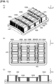
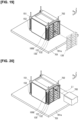
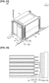
- Figure 1(A), Figure 1(B), and Figure 1(C) are a perspective view, a plan view, and a front view illustrating the battery pack according to the first embodiment.
- Figure 2 is a conceptual view illustrating the electrical connection between battery modules in a battery pack.
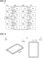
- Figure 3(A) and Figure 3(B) are a perspective view and a plan view illustrating a base member on which the battery modules are mounted.
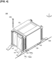
- Figure 4 is a perspective view illustrating a plurality of battery modules 100 that constitute a battery pack 10.
- Figure 5(A) and Figure 5(B) are a plan view and a side view illustrating the battery module of Figure 4 .
- Figure 6 is a cross-sectional view illustrating a state in which battery modules are mounted on a base portion by means of bolts and brackets.
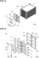
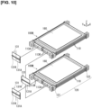
- Figure 7 is a perspective view illustrating a state in which the entire stacked body, in a state in which an upper pressure plate, a lower pressure plate, and left and right side plates are disassembled from a battery module and a protective cover is attached thereto, is exposed.
- Figure 8 is a perspective view illustrating a state in which the protective cover is detached from the stacked body illustrated in Figure 7 and the stacked body is disassembled into a cell group and a bus bar unit.
- Figure 9 is an exploded perspective view illustrating the bus bar unit illustrated in Figure 8 .
- Figure 10 is an exploded perspective view schematically illustrating a state in which an anode side electrode tab of a first cell sub-assembly (set of three of the unit cells connected in parallel) and a cathode side electrode tab of a second cell sub-assembly (set of three of the unit cells connected in parallel) are joined by means of a bus bar.
- Figure 11(A) is a perspective view illustrating a state in which a pair of spacers (first spacer and second spacer) is attached to a unit cell
- Figure 11(B) is a perspective view illustrating a state in which the pair of spacers (first spacer and second spacer) is detached from the unit cell
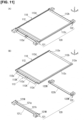
- Figure 12 is a perspective view illustrating a pair of spacers (first spacer and second spacer).
- Figure 13(A) is a perspective view illustrating a cross-section of the principle part of a state in which a bus bar is joined to the electrode tabs of stacked unit cells
- Figure 13(B) is a side view illustrating Figure 13(A) as viewed from the side.
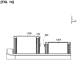
- Figure 14 is a view illustrating a comparative example for describing the attachment position of the inter-module bus bar in the battery module.
- the left front side is referred to as the "front side” of the entire battery module 100 and of each component part
- the right rear side is referred to as the “rear side” of the entire battery module 100 and of each component part
- the right front side and the left rear side are referred to as the left and right “lateral sides” of the entire battery module 100 and of each component part.
- the battery pack 10 comprises a plurality of battery modules 100A, 100B that is equipped with a plurality of unit cells 110 that is formed into a flat shape and is stacked in the thickness direction, and also is equipped with an anode side terminal 133 and a cathode side terminal 134 for carrying out the input and output of electric power, and a base member 310 configuring a base portion 300, on which the plurality of battery modules 100A, 100B is mounted.
- the anode side terminal 133 and the cathode side terminal 134 are disposed at an end portion of a side opposite to the base member 310, and the battery modules 100A, 100B are arranged on a mounting portion 311 of the base member 310 along the mounting portion 311.
- the battery pack 10 comprises inter-module bus bars 410, 420, 430 that electrically connect adjacent battery modules to each other, and a wiring 440 disposed in the electrical terminal end positions of the plurality of battery modules 100A, 100B, which are electrically connected.
- an upper pressure plate 151 and a lower pressure plate 152 are disposed at an end portion in the stacking direction Z of a cell group 100G in which unit cells 110 are stacked, and side plates 153 (corresponding to a pair of second cover members) are disposed at both ends in the short side direction Y that intersects the stacking direction Z and that intersects a longitudinal direction X in which the electrode tabs 113 protrude.
- the battery pack 10 comprises a battery module 100A and a battery module 100B in which the number of stacked layers of unit cells 110 are different.
- the battery modules 100A, 100B are not stacked on the base member 310 but are disposed on one level.
- the battery modules 100A, 100B are disposed such that the surfaces on which terminals that carry out the input and output of electric power are positioned facing each other, as illustrated in Figure 1(A) and Figure 1(C) .
- battery modules in the same row in Figure 1(B) are all configured to face the same direction.
- the battery module 100A is configured by stacking 27 of the unit cells 110
- the battery module 100B is configured by stacking 21 of the unit cells 110.
- the numbers of stacked layers are provided merely as examples and are not limited thereto. In this manner, since the battery module 100A and the battery module 100B have a different number of stacked layers of the unit cells 110, the specifications of the side plates 153 that cover the cell group 100G from the short side direction Y are different.
- the battery module 100A has a higher number of stacked layers of the unit cells 110 than the battery module 100B; accordingly, the height of the side plate 153 is configured to be higher in the battery module 100A than in the battery module 100B.
- the upper pressure plate 151 and the lower pressure plate 152 which cover the cell group 100G from the outer side in the stacking direction Z, are not affected by the number of stacked layers of the unit cells 110. Therefore, the battery module 100A and the battery module 100B can share components.
- the upper pressure plate 151, the lower pressure plate 152, and the side plate 153 will be described in detail later.
- the base portion 300 comprises a base member 310 on which the battery modules 100A, 100B are mounted and brackets 320, bolts 330, and nuts 340, for attaching the battery modules 100A, 100B to the base member 310, as illustrated in Figure 3 , Figure 4 , and Figure 6 .
- the base member 310 comprises a mounting portion 311 for mounting the battery modules 100A, 100B and a flange portion 312 provided on the outer side of the mounting portion 311, as illustrated in Figure 3(A) and Figure 3(B) .
- the mounting portion 311 is formed flat, but it may be a shape other than a flat shape, as long as the battery modules 100A, 100B can be mounted thereon.
- the flange portion 312 is configured by bending a flat plate material, or the like, so as to be able to attach brackets, for example, when mounting the battery pack 10 on a vehicle.
- the battery modules 100A, 100B comprise stacking portions 100C corresponding to the portion on which the unit cells 110 are stacked, and insertion portions 100D into which bolts 330 for attaching the battery modules 100A, 100B to the base member 310 are inserted, as illustrated in Figure 6 .
- the length of the insertion portion 100D in the stacking direction Z is configured to be shorter than that of the stacking portion 100C.
- a stepped recessed portion 100F is formed from the stacking portion 100C to the insertion portion 100D.
- the bracket 320 is prepared for mounting the battery modules 100A, 100B on the base member 310.
- the bracket 320 is disposed between the battery module 100A or the battery module 100B and the base member 310, fitting the shape of the recessed portion 100F from the stacking portion 100C to the insertion portion 100D of the battery modules 100A, 100B, as illustrated in Figure 6 . Accordingly, the bracket can function as a reinforcing material for the attachment site when attaching the battery modules 100A, 100B to the base member 310.
- the bracket 320 is joined to the base member 310 by welding in the present embodiment, but it may be joined by a method other than welding, as long as the battery modules 100A, 100B can be mounted.
- the bolt 330 is extended through the plurality of unit cells 110 constituting the battery modules 100A, 100B in a direction that intersects with the mounting portion 311 of the base member 310, to attach the battery modules 100A, 100B to the bracket 320, together with the nut 340. Since the bracket 320 is joined to the base member 310, the battery modules 100A, 100B are attached to the base portion 300 by attaching the battery modules 100A, 100B to the bracket 320, as illustrated in Figure 6 . The battery modules 100A, 100B are mounted on the base member 310, in a state in which the unit cells 110 are stacked in the stacking direction Z.
- the bolt 330 is inserted in the stacking direction of the battery modules 100A, 100B, that is, stacking direction Z in the present embodiment, according to the stacking mode of the unit cells 110, and fastened to the nut 340.
- the head portion of the bolt 330 is configured so as not to exceed the upper pressure plate 151 positioned on the upper portion of the stacking portion 100C, as illustrated in Figure 6 .
- the inter-module bus bars 410, 420, 430 are used for connecting adjacent battery modules in the battery pack 10, as illustrated in Figure 1(B) and Figure 2 .
- the inter-module bus bar 410 electrically connects battery modules that are adjacent in the same column in Figure 1(B) to each other (for example, refer to the battery modules of (1) and (2) in Figure 2 ).
- the inter-module bus bar 420 electrically connects battery modules between adjacent columns and whose positions in the rows are different, i.e., battery modules that are in a so-called oblique positional relationship (for example, refer to the battery modules (2) and (3) in Figure 2 ).
- the inter-module bus bar 430 electrically connects battery modules between adjacent columns and whose positions in the rows are the same (for example, refer to the battery modules (4) and (5) in Figure 2 ).
- the battery modules are electrically connected in the order of (1) to (16) in Figure 2 , by arranging the inter-module bus bars 410, 420, 430, as illustrated in Figure 1(A) and Figure 1(B) .
- Figure 2 is merely an example, and no limitation is imposed thereby.
- the inter-module bus bars 410, 420, 430 are fastened to the battery modules 100A, 100B by means of bolts 450 on the upper surfaces of the battery modules 100A, 100B.
- the inter-module bus bars 420 can be made relatively short.
- the wiring 440 is connected to a terminal portion, which is not shown, positioned on the left in Figure 1(B) and Figure 2 , and which becomes an outlet for electric power that is generated by the plurality of battery modules 100A, 100B.
- the battery module 100 comprises a stacked body 100S including a cell group 100G formed by stacking a plurality of unit cells 110 having a flat shape in the thickness direction, as illustrated in Figure 4 and Figure 7 .
- the battery module 100 further comprises a protective cover 140 attached on the front side of the stacked body 100S and a chassis 150 that houses the stacked body 100S in a state in which each unit cell 110 is pressurized along the stacking direction of the unit cells 110.
- the stacked body 100S comprises a cell group 100G and a bus bar unit 130 attached to the front side of the cell group 100G and that integrally holds a plurality of bus bars 131, as illustrated in Figure 8 .
- the protective cover 140 covers and protects the bus bar unit 130.
- the bus bar unit 130 comprises a plurality of bus bars 131 and a bus bar holder 132 that integrally attaches the plurality of bus bars 131 in a matrix, as illustrated in Figure 9 .
- an anode side terminal 133 is attached to the terminal end on the anode side
- a cathode side terminal 134 is attached to the terminal end on the cathode side.
- the cell group 100G is configured by connecting, in series, a first cell sub-assembly 100M comprising three of the unit cells 110 electrically connected in parallel and a second cell sub-assembly 100N comprising three different unit cells 110 electrically connected in parallel, by means of a bus bar 131, as illustrated in Figure 10 .
- the first cell sub-assembly 100M and the second cell sub-assembly 100N have the same configuration, excluding the folding directions of the distal end portions 113d of the electrode tabs 113 of the unit cells 110.
- the second cell sub-assembly 100N is one in which the top and bottom of the unit cells 110 included in the first cell sub-assembly 100M are reversed.
- the folding direction of the distal end portions 113d of the electrode tabs 113 of the second cell sub-assembly 100N is aligned on the lower side of the stacking direction Z so as to be the same as the folding direction of the distal end portions 113d of the electrode tabs 113 of the first cell sub-assembly 100M.
- a pair of spacers 120 (first spacer 121 and second spacer 122) is attached to each of the unit cells 110.
- the unit cell 110 corresponds to, for example, a flat lithium ion secondary battery.
- the unit cell 110 comprises a cell body 110H obtained by sealing a power generation element 111 with a pair of laminate films 112 (corresponding to an external casing), and a thin plate shaped electrode tab 113 that is electrically connected to the power generation element 111 and protruding out from the cell body 110H to the outside, as illustrated in Figure 13(A) and Figure 13(B) .
- the laminate film 112 is configured by laminating, for example, polyethylene or nickel.
- the power generation element 111 is formed by laminating a plurality of layers in which a positive electrode and a negative electrode are sandwiched by separators.
- the power generation element 111 is charged by receiving a supply of electric power from the outside, then it supplies electric power to an external electrical device while discharging.
- the laminate film 112 is configured by covering both sides of a metal foil with a sheet having an insulating property.
- the pair of laminate films 112 covers the power generation element 111 from both sides along the stacking direction Z to seal the four sides thereof.
- an anode side electrode tab 113A and a cathode side electrode tab 113K protrude out from between end portions 112a along the short side direction Y to the outside, as illustrated in Figure 11(B) .
- a pair of connecting pins 121i of the first spacer 121 is respectively inserted into a pair of connecting holes 112e respectively provided on both ends of the end portion 112a along the short side direction Y, as illustrated in Figure 11(B) and Figure 12 .
- a pair of connecting pins 122i is respectively inserted into a pair of connecting holes 112e respectively provided on both ends of the other end portion 112b along the short side direction Y.
- two end portions 112c and 112d along the longitudinal direction X are formed bent upward in the stacking direction Z.
- the electrode tab 113 is configured from an anode side electrode tab 113A and a cathode side electrode tab 113K, which respectively extend from between the one end portion 112a of a pair of laminate films 112 toward the outside, in a state of being separated from each other, as illustrated in Figure 11(B) , Figure 13(A), and Figure 13(B) .
- the anode side electrode tab 113A is made of aluminum, in accordance with the characteristics of the anode side component members in the power generation element 111.
- the cathode side electrode tab 113K is made of copper, in accordance with the characteristics of the cathode side component members in the power generation element 111.
- the electrode tab 113 is formed in an L shape running from a proximal end portion 113c adjacent to the cell body 110H to the distal end portion 113d, as illustrated in Figure 13(A) and Figure 13(B) . Specifically, the electrode tab 113 extends from the proximal end portion 113c thereof along one side in the longitudinal direction X. On the other hand, the distal end portion 113d of the electrode tab 113 is formed folded downward along the stacking direction Z.
- the shape of the distal end portion 113d of the electrode tab 113 is not limited to an L shape.
- the distal end portion 113d of the electrode tab 113 is formed in a planar shape so as to face the bus bar 131.
- the electrode tab 113 may be formed in a U shape by further extending the distal end portion 113d and by folding the extended portion along the proximal end portion 113c on the cell body 110H side.
- the proximal end portion 113c of the electrode tab 113 may be formed in a wave shape or a curved shape.
- the surface of the electrode tab 113 is disposed on the same side as the surfaces of the anode side terminal 133 and the cathode side terminal 134.
- each electrode tab 113 is aligned and folded downward in the stacking direction Z, as illustrated in Figure 13(B) .
- first cell sub-assembly 100M three of the unit cells 110 electrically connected in parallel
- second cell sub-assembly 100N three different unit cells 110 electrically connected in parallel
- the top and bottom of the unit cells 110 are interchanged every three of the unit cells 110, such that the positions of the anode side electrode tabs 113A and the cathode side electrode tabs 113K of the unit cells 110 crisscross along the stacking direction Z.
- the positions of the distal end portions 113d of the electrode tabs 113 will vary in the vertical direction along the stacking direction Z; therefore, all of the distal end portions 113d of the electrode tabs 113 of the unit cells 110 are adjusted and folded so that the positions thereof will be aligned.
- the anode side electrode tab 113A is disposed on the right side of the drawing and the cathode side electrode tab 113K is disposed on the left side of the drawing.
- the cathode side electrode tab 113K is disposed on the right side of the drawing and the anode side electrode tab 113A is disposed on the left side of the drawing.
- the distal end portion 113d of the electrode tab 113 of the unit cell 110 is folded downward along the stacking direction Z.
- the distal end portions 113d of the electrode tabs 113 are arranged on the same side of the stacked body 100S, as illustrated in Figure 13(B) .
- a double-sided tape 160 that is joined to a stacking member to be stacked above is adhered to the unit cells 110 positioned on the upper surfaces of the first cell sub-assembly 100M and the second cell sub-assembly 100N.
- a pair of spacers 120 are disposed between stacked unit cells 110, as illustrated in Figures 13(A), 13(B) , and the like.
- the first spacer 121 is disposed along one end portion 112a of the laminate film 112 where the electrode tab 113 of the unit cell 110 protrudes, as illustrated in Figure 11(A) .
- the second spacer 122 is disposed along the other end portion 112b of the laminate film 112, as illustrated in Figure 11(A) .
- the second spacer 122 has a configuration in which the shape of the first spacer 121 is simplified.
- a plurality of the unit cells 110 is stacked in the stacking direction Z, after attaching a pair of spacers 120 (first spacer 121 and second spacer 122) to each.
- the pair of spacers 120 (first spacer 121 and second spacer 122) are made of reinforced plastics having insulating properties.
- the first spacer 121 is formed in a rectangular parallelepiped shape, elongated along the short side direction Y, as illustrated in Figure 11(B) and Figure 12 .
- the first spacer 121 is provided with placing portions 121M and 121N on the two ends in the longitudinal direction thereof (short side direction Y).
- a positioning pin 121c provided on the upper surface 121a of one first spacer 121 is fitted with a positioning hole 121d that is opened on the lower surface 121b of another first spacer 121 and that corresponds to the position of the positioning pin 121c, as illustrated in Figure 12 and Figure 13(B) .
- a locating hole 121e for inserting a bolt that connects a plurality of unit cells 110 to each other along the stacking direction Z is opened in each of the placing portions 121M and 121N along the stacking direction Z, as illustrated in Figure 12 .
- the first spacer 121 is formed such that the region between the placing portions 121M and 121N is notched from the upper side of the stacking direction Z, as illustrated in Figure 11(B) and Figure 12 .
- the notched portion is provided with a first supporting surface 121g and a second supporting surface 121h along the longitudinal direction of the first spacer 121 (short side direction Y of the unit cell 110).
- the first supporting surface 121g is formed higher along the stacking direction Z and positioned further on the unit cell 110 side than the second supporting surface 121h.
- the first spacer 121 carries and supports the one end portion 112a of the laminate film 112, in which the electrode tab 113 is protruded, with the first supporting surface 121g, as illustrated in Figure 10(B).
- the first spacer 121 is provided with a pair of connecting pins 121i protruding upward from both ends of the first supporting surface 121g.
- the first spacer 121 is provided with a supporting portion 121j, which abuts the electrode tab 113 from the opposite side of the bus bar 131 and supports the distal end portion 113d of the electrode tab 113 of the unit cell 110, on the side surface adjacent to the second supporting surface 121h along the stacking direction Z, as illustrated in Figure 11(B) and Figure 12 .
- the supporting portion 121j of the first spacer 121 sandwiches the distal end portion 113d of the electrode tab 113 together with the bus bar 131 such that the distal end portion 113d and the bus bar 131 are sufficiently abutting each other.
- the second spacer 122 has a configuration in which the shape of the first spacer 121 is simplified, as illustrated in Figure 11(B) and Figure 12 .
- the second spacer 122 corresponds to a configuration in which a portion of the first spacer 121 is removed along the short side direction Y of the unit cell 110.
- the second spacer 122 is configured by replacing the second supporting surface 121h and the first supporting surface 121g of the first spacer 121 with a supporting surface 122k.
- the second spacer 122 is provided with placing portions 122M and 122N, in the same manner as the first spacer 121.
- the second spacer 122 is provided with the supporting surface 122k in the portion where the region between the placing portions 122M and 122N is notched from the upper side of the stacking direction Z.
- the supporting surface 122k carries and supports the other end portion 112b of the laminate film 112.
- the second spacer 122 is provided with a positioning pin 122c, a positioning hole, a locating hole 122e, and a connecting pin 122i, in the same manner as the first spacer 121.
- the bus bar unit 130 is integrally provided with a plurality of bus bars 131, as illustrated in Figure 8 and Figure 9 .
- the bus bar 131 is made of a metal having electrical conductivity, and it electrically connects the distal end portions 113d of the electrode tabs 113 of different unit cells 110 to each other.
- the bus bar 131 is formed in a flat plate shape and is erected along the stacking direction Z.
- the bus bar 131 is integrally formed by joining an anode side bus bar 131A that is laser-welded to an anode side electrode tab 113A of one unit cell 110, and a cathode side bus bar 131K that is laser-welded to a cathode side electrode tab 113K of another unit cell 110 adjacent along the stacking direction Z.
- the anode side bus bar 131A and the cathode side bus bar 131K have the same shape and are respectively formed in an L shape, as illustrated in Figure 9 and Figure 10 .
- the anode side bus bar 131A and the cathode side bus bar 131K are superimposed with the top and bottom inverted.
- the bus bar 131 is integrated by joining the folded portion of one end portion of the anode side bus bar 131A along the stacking direction Z and the folded portion of one end portion of the cathode side bus bar 131K along the stacking direction Z.
- the anode side bus bar 131A and the cathode side bus bar 131K are provided with side portions 131c on one end in the short side direction Y along the longitudinal direction X, as illustrated in Figure 9 .
- the side portions 131c are joined to the bus bar holder 132.
- the anode side bus bar 131A is made of aluminum, in the same manner as the anode side electrode tab 113A.
- the cathode side bus bar 131K is made of copper, in the same manner as the cathode side electrode tab 113K.
- the anode side bus bar 131A and the cathode side bus bar 131K made of different metals are joined to each other by ultrasonic joining.
- the battery module 100 is configured by connecting, in series, a plurality of sets of three of the unit cells 110 connected in parallel, as illustrated in Figure 9 , the anode side bus bar 131A portion of the bus bar 131 is laser-welded to the anode side electrode tabs 113A of three of the unit cells 110 that are adjacent to each other along the stacking direction Z.
- the cathode side bus bar 131K portion of the bus bar 131 is laser-welded to the cathode side electrode tabs 113K of three of the unit cells 110 that are adjacent to each other along the stacking direction Z.
- the bus bar 131 positioned on the upper right in the drawing in Figure 8 and Figure 9 corresponds to the anode side terminal ends of 21 of the unit cells 110 (3 parallel 7 series) and is configured only from an anode side bus bar 131A.
- This anode side bus bar 131A is laser-welded to the anode side electrode tabs 113A of the three uppermost unit cells 110 of the cell group 100G.
- the bus bar 131 positioned on the lower left in the drawing in Figure 8 and Figure 9 corresponds to the cathode side terminal ends of 21 of the unit cells 110 (3 parallel 7 series), and is configured only from a cathode side bus bar 131K.
- This cathode side bus bar 131K is laser-welded to the cathode side electrode tabs 113K of the three lowermost unit cells 110 of the cell group 100G.
- the bus bar holder 132 integrally holds a plurality of bus bars 131 in a matrix so as to face the electrode tab 113 of each of a plurality of stacked unit cells 110, as illustrated in Figure 9 .
- the bus bar holder 132 is made of resin having insulating properties and is formed in a frame shape.
- the bus bar holder 132 is respectively provided with a pair of columnar support portions 132a erected along the stacking direction Z, so as to be positioned on both sides of the longitudinal direction of the first spacer 121 that support the electrode tabs 113 of the unit cells 110, as illustrated in Figure 9 .
- the pair of columnar support portions 132a are fitted to the side surfaces of the placing portions 121M and 121N of the first spacer 121.
- the pair of columnar support portions 132a have an L shape when viewed along the stacking direction Z and are formed in a plate shape extended along the stacking direction Z.
- the bus bar holder 132 is provided with a pair of auxiliary columnar support portions 132b at an interval, erected along the stacking direction Z so as to be positioned in the vicinity of the center of the first spacer 121 in the longitudinal direction.
- the pair of auxiliary columnar support portions 132b are formed in a plate shape extended along the stacking direction Z.
- the bus bar holder 132 comprises insulating portions 132c that respectively protrude between adjacent bus bars 131 along the stacking direction Z, as illustrated in Figure 9 .
- the insulating portions 132c are formed in a plate shape extended along the short side direction Y.
- Each of the insulating portions 132c is provided horizontally between the columnar support portion 132a and the auxiliary columnar support portion 132b.
- the insulating portion 132c prevents discharge by insulating the space between bus bars 131 of the unit cells 110 that are adjacent to each other along the stacking direction Z.
- the bus bar holder 132 may be configured by joining the columnar support portion 132a, the auxiliary columnar support portion 132b, and the insulating portion 132c, which are independently formed, or be configured by integrally molding the columnar support portion 132a, the auxiliary columnar support portion 132b, and the insulating portion 132c.
- the anode side terminal 133 corresponds to the anode side terminal end of the cell group 100G configured by alternately stacking the first cell sub-assembly 100M and the second cell sub-assembly 100N, as illustrated in Figure 7 and Figure 9 .
- the anode side terminal 133 is joined to the anode side bus bar 131A positioned on the upper right in the drawing, from among the bus bars 131 arranged in a matrix, as illustrated in Figure 9 .
- the anode side terminal 133 is made of a metal plate having electrical conductivity, and, when viewed in plan view along the short side direction Y, it has a shape in which a flat plate shaped member is folded at folding points 133a, 133b, 133c at substantially 90 degrees or in an L shape.
- the surface from the folding point 133a to the end portion is laser-welded to the anode side bus bar 131A.
- the surface from the folding point 133c to the end portion faces the upper surface of the battery module 100 and connects any one of the inter-module bus bars 410, 420, 430, and is provided with a hole 133d (including the screw groove) opened in the center thereof.
- a bolt 450 is attached to the hole 133d to connect any one of the inter-module bus bars 410, 420, 430.
- the cathode side terminal 134 corresponds to the cathode side terminal end of the cell group 100G configured by alternately stacking the first cell sub-assembly 100M and the second cell sub-assembly 100N, as illustrated in Figure 9 .
- the cathode side terminal 134 is joined to the cathode side bus bar 131K positioned on the lower left in the drawing, from among the bus bars 131 arranged in a matrix, as illustrated in Figure 9 .
- the cathode side terminal 134 is configured to be capable of connecting any one of the inter-module bus bars 410, 420, 430 on the upper surface of the battery module 100, in the same manner as the anode side terminal 133.
- folding points 134a, 134b, 134c are formed, in which a flat plate material is folded at substantially 90 degrees or in an L shape in the same manner as the anode side terminal 133, as illustrated in Figure 9 .
- the surface below the folding point 134a is joined to the cathode side bus bar 131K by means of a laser, or the like.
- the surface from the folding point 134c to the end portion is provided with a hole 134d (including the screw groove) opened in the center thereof, in the same manner as the anode side terminal 133. Any one of the inter-module bus bars 410, 420, 430 is connected to the hole 134d.
- the protective cover 140 prevents the bus bars 131 from short-circuiting with each other and from coming in contact with an external member and being short-circuited or causing electrical leakage, by covering the bus bar unit 130, as illustrated in Figure 7 and Figure 8 . Furthermore, the protective cover 140 exposes the anode side terminal 133 and the cathode side terminal 134 to the outside and causes the power generation element 111 of each unit cell 110 to charge and discharge.
- the protective cover 140 is made of plastics having insulating properties.
- the protective cover 140 is formed in a flat plate shape and is erected along the stacking direction Z, as illustrated in Figure 8 .
- the protective cover 140 has a shape in which the upper end 140b and the lower end 140c of the side surface 140a thereof are folded along the longitudinal direction X and is fitted to the bus bar unit 130.
- the side surface 140a of the protective cover 140 is provided with a first opening 140d formed of a rectangular hole that is slightly larger than the anode side terminal 133, in order to join the anode side terminal 133 provided to the bus bar unit 130 to the anode side bus bar 131A, as illustrated in Figure 8 .
- the side surface 140a of the protective cover 140 is provided with a second opening 140e formed of a rectangular hole that is slightly larger than the cathode side terminal 134, in order to join the cathode side terminal 134 provided on the bus bar unit 130 to the cathode side bus bar 131K.
- the chassis 150 houses the cell group 100G in a state of being pressurized along the stacking direction Z, as illustrated in Figure 4 and Figure 5(B) .
- An appropriate surface pressure is imparted to the power generation element 111 by sandwiching and pressurizing the power generation element 111 of each unit cell 110 provided on the cell group 100G with the upper pressure plate 151 and the lower pressure plate 152.
- the height of the cell group 100G in the battery module 100 is configured to be lower than the height when the same number of unit cells 110 as that of the cell group 100G is stacked in a non-loaded state by means of the upper pressure plate 151 and the lower pressure plate 152.
- the upper pressure plate 151 is disposed above the cell group 100G along the stacking direction Z, as illustrated in Figure 4 and Figure 7 .
- the upper pressure plate 151 is provided with a pressing surface 151a protruding downward along the stacking direction Z in the center thereof.
- the power generation element 111 of each unit cell 110 is pressed downward by the pressing surface 151a.
- the upper pressure plate 151 is provided with a holding portion 151b extended along the longitudinal direction X from both sides along the short side direction Y.
- the holding portion 151b covers the placing portions 121M and 121N of the first spacer 121 or the placing portions 122M and 122N of the second spacer 122.
- a locating hole 151c which communicates with the positioning hole 121d of the first spacer 121 or the positioning hole 122d of the second spacer 122 along the stacking direction Z, is opened in the center of the holding portion 151b.
- a bolt 330 that connects unit cells 110 with each other is inserted into the locating hole 151c.
- the upper pressure plate 151 is made of a metal plate having a sufficient thickness.
- the upper pressure plate 151 comprises a bent portion 151d formed by bending both ends in the short side direction Y that intersects the stacking direction Z, as a joint portion with the side plate 153, as illustrated in Figure 7 .
- the lower pressure plate 152 has the same configuration as the upper pressure plate 151 and is formed by reversing the top and bottom of the upper pressure plate 151, as illustrated in Figure 4 and Figure 7 .
- the lower pressure plate 152 is disposed below the cell group 100G along the stacking direction Z.
- the lower pressure plate 152 presses the power generation element 111 of each unit cell 110 upward with the pressing surface 152a protruding upward along the stacking direction Z.
- the lower pressure plate 152 comprises a bent portion 152d formed by bending both ends in the short side direction Y that intersects the stacking direction Z, as a joint portion with the side plate 153, as illustrated in Figure 7 .
- One pair of side plates 153 fixes the relative positions of the upper pressure plate 151 and the lower pressure plate 152 such that the upper pressure plate 151 and the lower pressure plate 152, which sandwich and press the cell group 100G from above and below in the stacking direction Z, are not separated from each other, as illustrated in Figure 4 and Figure 7 .
- the side plate 153 is made of a rectangular metal plate and is erected along the stacking direction Z.
- the pair of side plates 153 is disposed outward of the bent portion 151d of the upper pressure plate 151 and the bent portion 152d of the lower pressure plate 152, as illustrated in Figure 4 .
- the pair of side plates 153 is joined to the upper pressure plate 151 and the lower pressure plate 152 from both sides in the short side direction Y of the cell group 100G by laser welding.
- a linear welding portion 153c (corresponding to the joint portion) is formed by seam welding, or the like, at the upper end 153a portion that abuts the upper pressure plate 151 along the longitudinal direction X, as illustrated in Figure 5(B) .
- a linear welding portion 153d (corresponding to the joint portion) is formed by seam welding, or the like, at the lower end 153b portion that abuts the lower pressure plate 152 along the longitudinal direction X.
- the pair of side plates 153 covers and protects both sides of the cell group 100G in the short side direction Y.
- Figure 15 is a flowchart illustrating a method for producing the battery pack 10 according to the first embodiment.
- the method of producing the battery pack 10 comprises disposing the lower pressure plate 152 (Step ST1), stacking the unit cells 110 (Step ST2), disposing the upper pressure plate 151 (Step ST3), pressurization (Step ST4), joining the side plate 153 to the upper pressure plate 151 and the lower pressure plate 152 (Step ST5), joining the electrode tab 113 and bus bar 131 (Step ST6), joining the anode side terminal 133 and cathode side terminal 134 (Step ST7), attaching the battery modules 100A, 100B to the base member 310 (Step ST9), and attaching the inter-module bus bars 410, 420, 430 (Step ST10).
- Step ST1 to Step ST3 will be referred to as the stacking step
- Step ST4 will be referred to as the pressurizing step
- Step ST5 will be referred to as the first joining step
- Step ST6 and Step ST7 will be referred to as the second joining step
- Steps ST9 and 10 will be referred to as the attaching step.
- the steps described above are referred to for convenience of description and do not need to be termed or distinguished as described above, as long as each of the following operations are the same.
- Step ST1 to Step ST3 the stacking step for stacking the members configuring the battery modules 100A, 100B (Step ST1 to Step ST3) will be described, with reference to Figure 16 .
- Figure 16 is a view illustrating the method for producing the battery pack 10 according to the first embodiment and a perspective view schematically illustrating a state in which members constituting the battery module 100 are sequentially stacked on a mounting table 701.
- the mounting table 701 used for the stacking step is formed in a plate shape and is provided along a horizontal plane.
- the mounting table 701 comprises locating pins 702 for positioning the relative positions of the lower pressure plate 152, the first cell sub-assembly 100M, the second cell sub-assembly 100N, and the upper pressure plate 151, which are sequentially stacked, along the longitudinal direction X and the short side direction Y.
- Four locating pins 702 are erected on the upper surface 701a of the mounting table 701 with predetermined intervals therebetween.
- the intervals between the four locating pins 702 from each other correspond, for example, to the intervals between the locating holes 152c provided on the four corners of the upper pressure plate 151.
- the members constituting the battery module 100 are stacked using a robot arm, a hand lifter, a vacuum adsorption type collet, or the like
- the lower pressure plate 152 is lowered along the stacking direction Z and mounted on the upper surface 701a of the mounting table 701, in a state in which the locating holes 152c provided on the four corners thereof are inserted into the locating pins 702 by means of a robot arm, as illustrated in Figure 16 (Step ST1).
- the first cell sub-assembly 100M having unit cells 110 is lowered along the stacking direction Z, in a state in which the locating holes provided to the first spacer 121 and the second spacer 122, which are component members thereof, are inserted to the locating pins 702 by means of a robot arm.
- the first cell sub-assembly 100M is stacked on the lower pressure plate 152.
- Step ST2 three sets each of the second cell sub-assembly 100N and the first cell sub-assembly 100M having unit cells 110 are alternately stacked by means of the robot arm (Step ST2).
- a double-sided tape 160 that is joined to a stacking member to be stacked above is adhered to the upper surfaces of the first cell sub-assembly 100M and the second cell sub-assembly 100N.
- the upper pressure plate 151 is lowered along the stacking direction Z and stacked on the first cell sub-assembly 100M, in a state in which the locating holes 151c provided on the four corners thereof are inserted into the locating pins 702 by means of a robot arm (Step ST3).
- Figure 17 is a perspective view schematically illustrating a state in which the component members of the battery module 100 are pressed from above, following Figure 16 .
- a pressurizing jig 703 used in the pressurizing step comprises a pressurizing portion 703a that is formed in a plate shape and provided along a horizontal plane and a supporting portion 703b that is formed in a cylindrical shape and that is erected and joined to the upper surface of the pressurizing portion 703a.
- the supporting portion 703b connects a hydraulic cylinder and an electric stage that are driven along the stacking direction Z.
- the pressurizing portion 703a moves above and below along the stacking direction Z via the supporting portion 703b.
- the pressurizing portion 703a pressurizes the abutted stacking members (Step ST4).
- the pressurizing portion 703a of the pressurizing jig 703 is lowered downward along the stacking direction Z while being abutted on the upper pressure plate 151 by means of the electric stage connected to the supporting portion 703b being driven, as illustrated in Figure 17 .
- the cell group 100G is sandwiched and pressurized by means of the upper pressure plate 151 that is pressed downward and the lower pressure plate 152 that is mounted on the mounting table 701.
- An appropriate surface pressure is imparted to the power generation element 111 of each unit cell 110 provided on the cell group 100G.
- the pressurizing step is continued until the next joining step is completed.
- Figure 18 is a perspective view schematically illustrating a state in which the side plates 153 are laser-welded to the upper pressure plate 151 and the lower pressure plate 152, following Figure 17 .
- a pushing plate 704 used in the first joining step respectively presses the side plates 153 against the upper pressure plate 151 and the lower pressure plate 152, to respectively bring the side plates 153 in close contact with the upper pressure plate 151 and the lower pressure plate 152.
- the pushing plate 704 is made of metal and formed in an elongated plate shape.
- a linear slit 704b is opened in a main body 704a of the pushing plate 704 along the longitudinal direction.
- the short side direction of the pushing plate 704 is erected along the stacking direction Z.
- the pushing plate 704 presses the side plate 153 with the main body 704a and allows laser light L1 for welding to pass through the slit 704b.
- a laser oscillator 705 entails a light source for joining the side plates 153 to the upper pressure plate 151 and the lower pressure plate 152.
- the laser oscillator 705 is configured from, for example, a YAG (yttrium aluminum garnet) laser.
- the laser light L1 that is led out from the laser oscillator 705 is irradiated onto the upper end 153a and the lower end 153b of the side plate 153, in a state in which the light path is adjusted, for example, by means of an optical fiber or a mirror and condensed by means of a condenser lens.
- the laser light L1 that is led out from the laser oscillator 705 may be split by means of a half-mirror and irradiated onto the upper end 153a and the lower end 153b of the side plate 153 at the same time.
- a laser oscillator 705 horizontally scans laser light L1 onto the upper end 153a of the side plate 153 that is pressed by the pushing plate 704 via the slit 704b of the pushing plate 704 and subjects the side plate 153 and the upper pressure plate 151 to seam welding at a plurality of locations, as illustrated in Figure 18 .
- the laser oscillator 705 horizontally scans laser light L1 onto the lower end 153b of the side plate 153 that is pressed by the pushing plate 704 via the slit 704b of the pushing plate 704 and subjects the side plate 153 and the lower pressure plate 152 to seam welding at a plurality of locations (Step ST5).
- Figure 19 is a perspective view schematically illustrating a state in which a part of the members of the bus bar unit 130 is attached to the cell group 100G, following Figure 18 .
- Figure 20 is a perspective view schematically illustrating a state in which the bus bar 131 of the bus bar unit 130 is laser-welded to the electrode tabs 113 of the unit cell 110, following Figure 19 .
- Figure 21 is a side view illustrating a cross-section of the principle part of a state in which the bus bar 131 is laser-welded to the electrode tabs 113 of the stacked unit cells 110.
- the mounting table 701 rotates 90 degrees counterclockwise in the drawing to cause the electrode tabs 113 of the cell group 100G and the laser oscillator 705 to face each other, as illustrated in Figure 19 and Figure 20 .
- the bus bar holder 132 by which the bus bars 131 are integrally held, is kept pressed while being abutted on the corresponding electrode tabs 113 of the cell group 100G by means of a robot arm.
- the laser oscillator 705 irradiates the laser light L1 onto the bus bar 131 and joins the bus bar 131 and the distal end portions 113d of the electrode tabs 113 by seam welding or spot welding, as illustrated in Figure 20 and Figure 21 .
- the anode side terminal 133 is joined to the anode side bus bar 131A corresponding to the anode side terminal end (upper right in Figure 9 ), from among the bus bars 131 arranged in a matrix, as illustrated in Figure 21 .
- the cathode side terminal 134 is joined to the cathode side bus bar 131K corresponding to the cathode side terminal end (lower left in Figure 9 ), from among the bus bars 131 arranged in a matrix (Step ST6).
- Figure 22 is a perspective view schematically illustrating a state in which a protective cover is attached to a bus bar unit, and an anode side terminal and a cathode side terminal are laser-welded to an anode side bus bar and a cathode side bus bar, following Figure 20 and Figure 21 .
- a protective cover 140 is attached to the bus bar unit 130 while fitting the upper end 140b and the lower end 140c of the protective cover 140 to the bus bar unit 130, using the robot arm.
- the upper end 140b and the lower end 140c of the protective cover 140 may be joined to the bus bar unit 130 by means of an adhesive.
- laser light is irradiated from the first opening 140d to weld the anode side terminal 133 to the anode side bus bar 131A, as illustrated in Figure 22 .
- laser light is irradiated from the second opening 140e to weld the cathode side terminal 134 to the cathode side bus bar 131K (Step ST7).
- the protective cover 140 covers the bus bar unit 130 to prevent the bus bars 131 from short-circuiting with each other and from coming in contact with an external member and being short-circuited or causing electrical leakage. Thereafter, the battery module 100 is removed from the mounting table 701 and carried out to an inspection step for inspecting the battery performance, and the like.
- the battery pack 10 uses 16 battery modules, as illustrated in Figure 1(A), Figure 1(B) , and the like. At this time, only one battery module has been formed (Step ST8: NO). Therefore, Step ST1 to Step ST7 are repeated until a total of 16 battery modules 100A, 100B have been prepared. As described above, the battery module 100A and the battery module 100B have different numbers of stacked layers of the unit cell 110 and different specifications of the side plates 153. Accordingly, in Step S2, the number of stacked layers of the unit cells 110 is changed according to the specification of the battery module. In the same manner, in Step ST5, the specification of the side plate 153 to be used is changed according to the specification of the battery module.
- Step ST8 When a total of 16 battery modules 100A, 100B have been prepared (Step ST8: YES), the battery modules 100A, 100B are attached to the base member 310 using brackets 320, bolts 330, and nuts 340, in the attaching step (Step ST9).
- the battery modules 100A, 100B are not stacked in a direction crossing the base portion 300 and are disposed on one level. Then, one of the inter-module bus bars 410, 420, 430 or the wiring 440 is attached to the battery modules 100A, 100B (Step ST10).
- Step ST1 to Step ST10 may be embodied by an automatic machine in which all of the steps are controlled by means of a controller, a semiautomatic machine in which a portion of the steps are carried out by a worker, or a manual machine in which all of the steps are carried out by a worker.
- the attachment portions of the inter-module bus bars 410, 420, 430 or the wiring 440 attached to each of the anode side terminal 133 and the cathode side terminal 134 of the battery modules 100A, 100B are disposed on an end portion on the opposite side of the base member 310 side, and the battery modules 100A, 100B are arranged on a mounting portion 311 of the base member 310 along the mounting portion. Since the number of unit cells 110 and battery modules 100 attain a large number, by configuring as described above, it becomes unnecessary to dispose the inter-module bus bar 410, etc. on the lower portion near the base portion 300.
- inter-module bus bar 410 In the inter-module bus bar 410, and the like, components of the battery pack are not disposed on the opposite side of the base member 310. Therefore, the space in which components of the battery pack are not present can be used as an operating space when attaching the inter-module bus bar 410, and the like. Therefore, it is possible to not provide, or make it difficult to provide, an operating space between adjacent battery modules. Accordingly, it is possible to achieve a battery pack that can be assembled, even if the intervals between battery modules are relatively small. In addition, by being able to make the intervals between battery modules relatively small, the proportion of the space occupied by the battery modules among the entire battery pack can be increased, which could lead to downsizing of the battery pack. In addition, the effect described above can be exerted by disposing the battery modules 100A, 100B on one level, without stacking, on the base member 100A, 100B.
- adjacent columns in Figure 1(C) are configured to oppose the anode side terminal 133 and the cathode side terminal 134 of the battery module 100B. Accordingly, at this site, it is possible to shorten the inter-module bus bar 420 and to make the layout of the bus bar compact.
- the surface of the electrode tab 113 is disposed on the same side as the surfaces of the anode side terminal 133 and the cathode side terminal 134. Accordingly, it is possible to make the length of the component necessary for electrical connection, not only between battery modules, but also between the electrode tab and the terminal, relatively short.
- the bolts 450 are inserted in the stacking direction Z, but no limitation is imposed thereby; the bolts 450 may be attached on the side surface of the battery module 100, as long as the operating space for bolts 450, and the like, can be reduced between adjacent battery modules.
- the height from the base member 310 of the anode side terminal 133 and the cathode side terminal 134 of the battery module 100A opposing each other, and the height from the base member 310 of the anode side terminal 133 and the cathode side terminal 134 of the battery module 100B, are preferably configured to be different, as illustrated in Figure 1(C) .
- the bolt attachment position of the inter-module bus bar of a battery module having a high number of stacked layers is preferably provided at a position higher than the upper portion of a battery module having a low number of stacked layers, from the point of view of operating space.
- bolts 330 are inserted into a plurality of unit cells 110 in a direction crossing the base portion 300 and fastened to nuts 340, to thereby fix the battery modules 100A, 100B to the base member 310 via brackets 320.
- the operating space for the bolts to be inserted into the unit cells in the battery module changes depending on how the battery module is placed with respect to the base portion. If the battery module were disposed such that the unit cells are stacked parallel to the base portion, tools, etc. could enter along the direction of the gap between the battery modules; therefore, more operating space becomes necessary.
- by inserting the bolts 330 in a direction that crosses the base portion 300 it is possible to effectively utilize the space in which components of the battery pack are not present, to reduce the required operating space between the battery modules.
- brackets 320 are connected to the battery modules 100A, 100B, by being fitted to the shape of a recessed portion 100F formed from the stacking portion 100C to the insertion portion 100D, whose length in the stacking direction Z is shorter than that of the stacking portion 100C. Accordingly, even if external force acts on the battery pack 10, it is possible the brackets 320 may be caused to function to strengthen the rigidity of the portion of the insertion portion 100D.
- the site of the head portion of the bolt is configured to have a length that does not exceed the upper pressure plate 151 positioned at the end portion of the stacking portion 100C, as illustrated in Figure 6 . Accordingly, it is possible to reduce the volume of the entire battery pack, compared to a case in which the bolt protrudes farther than the stacking portion. Therefore, when mounting the battery pack 10 on, for example, a vehicle, it becomes advantageous with regard to the clearance of adjacent components, and the like, and it becomes possible to improve the applicability of the battery pack 10.
- the side plates 153 are joined by welding to the upper pressure plate 151 and the lower pressure plate 152 in a state in which the cell group 100G is pressurized in the stacking direction Z by means of the upper pressure plate 151 and the lower pressure plate 152. Accordingly, it is possible to firmly fix the cell group 100G using the upper pressure plate 151, lower pressure plate 152, and the side plate 153 and to improve reliability with respect to shock.
- the battery modules 100A, 100B are configured to use the same upper pressure plate 151 and lower pressure plate 152, regardless of the number of stacked layers of unit cells 110.
- members such as the side plate 153 related to the stacking direction Z in accordance with the number of stacked layers are changed according to the number of stacked layers of unit cells 110. Accordingly, it is possible to flexibly adjust the number of unit cells to be mounted on one battery module. Therefore, it is possible to flexibly adjust the layout, performance, and the like of the battery pack.
- Figure 23 is a perspective view illustrating battery modules according to the second embodiment
- Figure 24 is a partial cross-sectional view illustrating the inside of a battery module in the battery pack according to the second embodiment.
- first cell sub-assembly 100M and a second cell sub-assembly, in each of which three of the unit cells 110 are stacked, are stacked between an upper pressure plate 151 and a lower pressure plate 152.
- a heat dissipation member 270 (corresponding to a heat transfer member) that dissipates heat that may be generated to the outside when using the battery pack, is disposed between the first cell sub-assembly 100M and the second cell sub-assembly 100N, as illustrated in Figure 23 and Figure 24 .
- the heat dissipation member 270 comprises a cell contact portion 271 that comes in contact with the first cell sub-assembly 100M or the second cell sub-assembly 100N and a heat dissipation portion 272 that comes in contact with a side plate 153, which is an outer wall, for dissipating heat obtained from the cell contact portion 271 to the outside.
- the side plate 153 comes in contact with the heat dissipation member 270 via an insulating member 280.
- the heat dissipation member 270 is configured from a material such as aluminum, having a thermal conductivity rate that is higher than the laminate film 112 that covers the power generation element 111 of the unit cell 110, excluding the electrode tab 113.
- a flat plate made of aluminum, or the like may be bent at the end portions, the vicinity of the center may be set as the cell contact portion 271, and the bent end portions may be set as the heat dissipation portion 272.
- An insulating member 280 may be disposed on the outside of the side plate 153, and a water jacket 290, or the like, may be disposed further on the outside thereof, to carry out heat dissipation, and the like.
- one heat dissipation member 270 is disposed between the fourth and fifth unit cells 110 from the bottom.
- the number and positions of the heat dissipation members 270 are not limited to the above and may be changed appropriately.
- a gap may be provided between the cell group 100G and the side plate 153, and outside air may be introduced to the gap portion.
- the configurations of the heat dissipation member 270, the insulating member 280, and the water jacket 290 are different from the first embodiment, and the other configurations are the same as the first embodiment; therefore, descriptions of the other configurations are omitted.
- the second embodiment is configured to dispose a heat dissipation member 270 having a higher thermal conductivity rate than the laminate film 112, in any position in the stacking direction Z of the cell group 100G, in which a first cell sub-assembly 100M and a second cell sub-assembly 100N are stacked.
- a chassis is configured from a side plate 153, whose dimensions are changed according to the number of stacked layers of the unit cells 110, an upper pressure plate 151, and a lower pressure plate 152, regardless of the number of stacked layers of the unit cells 110, in the same manner as the first embodiment.
- the number and positions of the heat dissipation members 270 according to the present embodiment may be freely adjusted according to modes in which the unit cells 110 are connected in parallel or series, in other words, according to the heat dissipation amount per unit volume. In this way, the battery pack 10 can be efficiently cooled.
- Figure 25(A) and Figure 25(B) are a schematic perspective view and a schematic plan view of modified examples of Figure 1(A) and Figure 1(B) .
- Figure 25(A) and Figure 25(B) drawings of the inter-module bus bar and the wiring are omitted for convenience of description.
- the battery pack 10a may be configured from a battery module 100A in which unit cells 110 are stacked in a direction perpendicular to the mounting portion 311 of the base member 310, and a battery module 100E in which unit cells 110 are stacked in a direction parallel to the mounting portion 311, as illustrated in Figure 25(A) and Figure 25(B) .
- vertical mounting a case in which unit cells 110 are disposed parallel to the base portion 300, as in the battery module 100E
- horizontal mounting By arranging the battery module horizontally on the base member 310, as in the battery module 100E, it is possible to dispose the battery modules without being restricted by the width dimension of the battery module 100 when viewed in plan view from the stacking direction.
- the battery module 100 according to the first and second embodiments since the number of stacked layers of the unit cells can be freely adjusted, it is possible to efficiently dispose the battery modules in a small space by disposing horizontally.
- the battery modules constituting the battery pack entail two types of battery modules 100A, 100B, but no limitation is imposed thereby.
- the number of types of battery modules may be two or more, or it may be one.
- the number of battery modules disposed in the battery pack 10 was described as 16, which is merely an example, and is not limited to 16.
- bus bars are joined to each other by ultrasonic joining and the electrode tabs and the bus bars are joined by laser welding, but no limitation is imposed thereby.
- the bus bars, or the electrode tabs and the bus bars may be joined by welding.
- adjacent electrode tabs are joined to the bus bar, but no limitation is imposed thereby.
- the electrode tabs may be joined to each other by ultrasonic joining or welding.
- Figure 26 is a cross-sectional view cut along the stacking direction of a battery module and a cross-sectional view illustrating a modified example of the first embodiment.
- a cell group 100G obtained by stacking a plurality of unit cells 110 is disposed between an upper pressure plate 151 and a lower pressure plate 152, which configure a chassis 150.
- an elastic member 370 that generates elastic force in the stacking direction Z may be provided in addition to the plurality of unit cells 110.
- the elastic member 370 is disposed in one position in the stacking direction Z.
- the elastic member 370 comprises elastic members 371, 372, which are mainly elastically deformed in the substantially center position in Figure 26 , and is joined to an adjacent member at point a1.
- the elastic member 370 is joined to an adjacent member, but is preferably joined to a plate-shaped intermediate member 380, as illustrated in Figure 26 .
- the elastic member 371 and the elastic member 372 are joined at point b1, which is further outward than point a1.
- the elastic member 370 absorbs the changes in the thickness direction, and it is possible to prevent the movement of the unit cells 110 when external force is applied.
Landscapes
- Chemical & Material Sciences (AREA)
- Chemical Kinetics & Catalysis (AREA)
- Electrochemistry (AREA)
- General Chemical & Material Sciences (AREA)
- Engineering & Computer Science (AREA)
- Manufacturing & Machinery (AREA)
- Battery Mounting, Suspending (AREA)
- Connection Of Batteries Or Terminals (AREA)
- Secondary Cells (AREA)
Description
- The present invention relates to a battery pack and a method for producing same.
- In recent years, in the automobile industry, the development of secondary batteries and fuel cells have been widely carried out, from the point of view of environmental protection and fuel economy. Since the output of each battery in a secondary battery is not very high, a desired number thereof are stacked to form a battery module, in order to enable cruising speed in an automobile possible. In addition, there are cases in which a predetermined number of battery modules are assembled into a battery pack (also called an assembled battery). As a conventional technique relating to battery packs,
JP 2015-5361 A
US 2015/0037642 A1 discloses a battery pack, comprising a plurality of battery modules each including a plurality of unit cells stacked in a thickness direction of the battery module, each of the unit cells having a flat shape and positive and negative terminals for transferring input and output of electric power; each unit cell comprises a cell body that includes a power generation element and an electrode tab drawn out from the cell body. Each of the plurality of battery modules comprises: a pair of first cover members for covering the stacked unit cells from both sides in the stacking direction of the unit cells, and a pair of second cover members for covering the stacked unit cells from both sides in a direction that intersects with the stacking direction of the unit cells and that also intersects with a direction in which the electrode tabs extend.
JP 2013-229266 A - A battery pack requires many battery cells and battery modules in order to generate a predetermined amount of electric power. Accordingly, numerous wirings for withdrawing electric power from the battery pack also become necessary. Since a battery pack requires many such wirings, depending on the manner in which the wirings are attached, the layout of the battery pack changes significantly, and there is the risk that the operating space for producing the battery pack will be affected.
- An object of the present invention is to provide a battery pack that improves the efficiency of the operating space for attaching wiring to a battery module, and a method for producing the same.
- The present invention for achieving the object described above provides a battery pack, comprising
- a plurality of battery modules each including a plurality of unit cells stacked in a thickness stacking direction, each of the plurality of unit cells having a flat shape and an anode side terminal and a cathode side terminal for transferring input and output of electric power; and
- a base member on which the plurality of battery modules is mounted, wherein
- the anode side terminal and cathode side terminal of each of the plurality of battery modules are disposed at an end portion of the battery module on a side of the battery module opposite the base member,
- the plurality of battery modules is arranged on a mounting surface of the base member for the plurality of battery modules, along the mounting surface,
- each of the plurality of unit cells comprises a cell body that includes a power generation element and an electrode tab protruding out from the cell body in a longitudinal direction,
- each of the plurality of battery modules comprises:
- a pair of first cover members for covering the stacked unit cells from both sides in the stacking direction of the unit cells, and
- a pair of second cover members for covering the stacked unit cells from both sides in a short-side direction that intersects with the stacking direction of the unit cells and that also intersects with the longitudinal direction in which the electrode tabs extend, and
- the pair of second cover members is welded to the pair of first cover members in a state in which the stacked unit cells are pressurized in the stacking direction of the unit cells by means of the pair of first cover members,
- wherein
- each of the plurality of battery modules comprises a plurality of bus bars that is respectively joined to a plurality of electrode tabs of the stacked unit cells,
- the electrode tabs and the plurality of bus bars are welded while the bus bars are being abutted on the corresponding electrode tabs,
- the distal end portion of each electrode tab is formed in a planar shape so as to face a corresponding bus bar,
- each bus bar is formed in a flat plate shape and is erected along the stacking direction,
- each of the anode terminal and the cathode terminal is made of a metal plate having electrical conductivity,
- each anode side terminal has a shape in which the metal plate is folded at a first folding point, a second folding point and a third folding point in an L shape when viewed in plan view along the short-side direction,
- the surface from the first folding point to one end portion of each anode side terminal is laser-welded to the corresponding bus bar,
- the surface from the third folding point to the other end portion of the anode side terminal faces the upper surface of the battery module,
- each cathode side terminal has a shape in which the metal plate is folded at a first folding point, a second folding point and a third folding point in an L shape when viewed in plan view along the short-side direction,
- the surface from the first folding point to one end portion of each cathode side terminal is laser-welded to the corresponding bus bar,
- the surface from the third folding point to the other end portion of the anode side terminal faces the upper surface of the battery module.
- The present invention for achieving the object described above is a method for producing a battery pack, comprising a plurality of battery modules each including a plurality of unit cells stacked in a thickness stacking direction, wherein
- each of the plurality of unit cells has
- a flat shape,
- an anode side terminal and a cathode side terminal for transferring input and output of electric power,
- a cell body that includes a power generation element, and
- an electrode tab protruding out from the cell body in a longitudinal direction,
- the distal end portion of each electrode tab is formed in a planar shape so as to face the bus bar,
- each bus bar is formed in a flat plate shape and is erected along the stacking direction,
- each of the anode terminal and the cathode terminal is made of a metal plate having electrical conductivity,
- each anode side terminal has a shape in which the metal plate is folded at a first folding point, a second folding point and a third folding point in an L shape when viewed in plan view along a short-side direction that intersects with the stacking direction and that also intersects with the longitudinal direction in which the electrode tabs extend, and
the cathode side terminal has a shape in which the metal plate is folded at a first folding point, a second folding point and a third folding point in an L shape when viewed in plan view along the short-side direction, - for each of the plurality of battery modules,
- stacking the unit cells,
- disposing a pair of first cover members on both sides of the unit cells that are stacked in a stacking direction of the unit cells to pressurize the stacked unit cells in the stacking direction, and
- disposing a pair of second cover members on both sides of the unit cells stacked in the short-side direction to weld the pair of second cover members to the pair of first cover members,
- wherein
- pressurizing the stacked unit cells is continued until welding the pair of second cover members is completed,
- mounting the plurality of battery modules on a base member such that the terminals of each of the plurality of battery modules are positioned at an end portion of the battery module on a side of the battery module opposite the base member,
- arranging the plurality of battery modules on a mounting surface of the base member for the plurality of battery modules, along the mounting surface,
- joining respectively a plurality of bus bars of each of the plurality of battery modules to the plurality of electrode tabs of the stacked unit cells, and
- welding the electrode tabs and the plurality of bus bars while the bus bars are being abutted on the corresponding electrode tabs, and
- characterized by
- laser-welding the surface from the first folding point to one end portion of each anode side terminal to the corresponding bus bar,
- arranging the surface from the third folding point to the other end portion of the anode side terminal to face the upper surface of the battery module,
- laser-welding the surface from the first folding point to one end portion of each cathode side terminal to the corresponding bus bar, and
arranging the surface from the third folding point to the other end portion of the anode side terminal to face the upper surface of the battery module. -
- [
Figure 1] Figure 1 (A), Figure 1 (B), and Figure 1(C) are a perspective view, a plan view, and a front view illustrating the battery pack according to the first embodiment. - [
Figure 2 ] Conceptual view illustrating the electrical connection between battery modules in a battery pack. - [
Figure 3] Figure 3(A) and Figure 3(B) are a perspective view and a plan view illustrating a base member on which the battery modules are mounted. - [
Figure 4 ] Perspective view illustrating battery modules that constitute a battery pack. - [
Figure 5] Figure 5(A) and Figure 5(B) are a plan view and a side view illustrating the battery module ofFigure 4 . - [
Figure 6 ] Cross-sectional view illustrating a state in which battery modules are mounted on a base portion by means of bolts and brackets. - [
Figure 7 ] Perspective view illustrating a state in which the entire stacked body, in a state in which an upper pressure plate, a lower pressure plate, and left and right side plates are disassembled from a battery module and a protective cover is attached thereto, is exposed. - [
Figure 8 ] Perspective view illustrating a state in which the protective cover is detached from the stacked body illustrated inFigure 7 and the stacked body is disassembled into a cell group and a bus bar unit. - [
Figure 9 ] Exploded perspective view illustrating the bus bar unit illustrated inFigure 8 . - [
Figure 10 ] Exploded perspective view schematically illustrating a state in which an anode side electrode tab of a first cell sub-assembly (set of three of the unit cells connected in parallel) and a cathode side electrode tab of a second cell sub-assembly (set of three of the unit cells connected in parallel) are joined by means of a bus bar. - [
Figure 11] Figure 11 (A) is a perspective view illustrating a state in which a pair of spacers (first spacer and second spacer) are attached to a unit cell, andFigure 11 (B) is a perspective view illustrating a state in which the pair of spacers (first spacer and second spacer) is detached from the unit cell. - [
Figure 12 ] Perspective view illustrating the pair of spacers (first spacer and second spacer). - [
Figure 13] Figure 13(A) is a perspective view illustrating a cross-section of the principle part of a state in which a bus bar is joined to the electrode tabs of stacked unit cells, andFigure 13(B) is a side view illustratingFigure 13(A) as viewed from the side. - [
Figure 14 ] View illustrating a comparative example for describing the attachment position of the inter-module bus bar in the battery module. - [
Figure 15 ] Flowchart illustrating a method for producing a battery pack according to the first embodiment. - [
Figure 16 ] View illustrating the method for producing the battery pack according to the first embodiment, and a perspective view schematically illustrating a state in which members constituting the battery module are sequentially stacked on a mounting table. - [
Figure 17 ] Perspective view schematically illustrating a state in which the component members of the battery module are pressed from above, followingFigure 16 . - [
Figure 18 ] Perspective view schematically illustrating a state in which a side plate is laser-welded to an upper pressure plate and a lower pressure plate, followingFigure 17 . - [
Figure 19 ] Perspective view schematically illustrating a state in which a part of the members of the bus bar unit is attached to the cell group, followingFigure 18 . - [
Figure 20 ] Perspective view schematically illustrating a state in which the bus bar of the bus bar unit is laser-welded to the electrode tabs of the unit cell, followingFigure 19 . - [
Figure 21 ] Side view illustrating a cross-section of the principle part of a state in which the bus bar is laser-welded to the electrode tabs of the stacked unit cells. - [
Figure 22 ] Perspective view schematically illustrating a state in which a protective cover is attached to a bus bar unit, and an anode side terminal and a cathode side terminal are laser-welded to an anode side bus bar and a cathode side bus bar, followingFigure 20 andFigure 21 . - [
Figure 23 ] Perspective view illustrating battery modules that constitute a battery pack according to the second embodiment. - [
Figure 24 ] Partial cross-sectional view illustrating the inside of a battery module in the battery pack according to the second embodiment. - [
Figure 25] Figure 25(A) and Figure 25(B) are a schematic perspective view and a schematic plan view of modified examples ofFigure 1(A) and Figure 1(B) . - [
Figure 26 ] Cross-sectional view cut along the stacking direction of a battery module and a cross-sectional view illustrating a modified example of the first embodiment. - Embodiments of the present invention will be explained below, with reference to the appended drawings. In the explanations of the drawings, the same elements are given the same reference symbols, and overlapping explanations are omitted. The sizes and ratios of the members in the drawing are exaggerated for convenience of explanation, and may be different from the actual sizes and ratios. The orientation is shown using arrows indicated by X, Y, and Z in the drawings. The direction of the arrow indicated by X indicates a direction that intersects with the stacking direction of the
unit cell 110 and a direction along the longitudinal direction of theunit cell 110. The direction of the arrow indicated by Y indicates a direction that intersects with the stacking direction of theunit cell 110 and a direction along the short side direction of theunit cell 110. The direction of the arrow indicated by Z is the stacking direction of theunit cell 110. - First, a
battery pack 10 according to the first embodiment will be described with reference toFigures 1-14 . -
Figure 1(A), Figure 1(B), and Figure 1(C) are a perspective view, a plan view, and a front view illustrating the battery pack according to the first embodiment.Figure 2 is a conceptual view illustrating the electrical connection between battery modules in a battery pack.Figure 3(A) and Figure 3(B) are a perspective view and a plan view illustrating a base member on which the battery modules are mounted.Figure 4 is a perspective view illustrating a plurality ofbattery modules 100 that constitute abattery pack 10.Figure 5(A) and Figure 5(B) are a plan view and a side view illustrating the battery module ofFigure 4 .Figure 6 is a cross-sectional view illustrating a state in which battery modules are mounted on a base portion by means of bolts and brackets.Figure 7 is a perspective view illustrating a state in which the entire stacked body, in a state in which an upper pressure plate, a lower pressure plate, and left and right side plates are disassembled from a battery module and a protective cover is attached thereto, is exposed. -
Figure 8 is a perspective view illustrating a state in which the protective cover is detached from the stacked body illustrated inFigure 7 and the stacked body is disassembled into a cell group and a bus bar unit.Figure 9 is an exploded perspective view illustrating the bus bar unit illustrated inFigure 8 .Figure 10 is an exploded perspective view schematically illustrating a state in which an anode side electrode tab of a first cell sub-assembly (set of three of the unit cells connected in parallel) and a cathode side electrode tab of a second cell sub-assembly (set of three of the unit cells connected in parallel) are joined by means of a bus bar. -
Figure 11(A) is a perspective view illustrating a state in which a pair of spacers (first spacer and second spacer) is attached to a unit cell, andFigure 11(B) is a perspective view illustrating a state in which the pair of spacers (first spacer and second spacer) is detached from the unit cell.Figure 12 is a perspective view illustrating a pair of spacers (first spacer and second spacer).Figure 13(A) is a perspective view illustrating a cross-section of the principle part of a state in which a bus bar is joined to the electrode tabs of stacked unit cells, andFigure 13(B) is a side view illustratingFigure 13(A) as viewed from the side.Figure 14 is a view illustrating a comparative example for describing the attachment position of the inter-module bus bar in the battery module. - In the state illustrated in
Figure 1 , the left front side is referred to as the "front side" of theentire battery module 100 and of each component part, the right rear side is referred to as the "rear side" of theentire battery module 100 and of each component part, and the right front side and the left rear side are referred to as the left and right "lateral sides" of theentire battery module 100 and of each component part. - First, the battery pack will be described. To summarize with reference to
Figure 1(A)-Figure 1(C) ,Figure 7 , andFigure 11 , thebattery pack 10 comprises a plurality ofbattery modules unit cells 110 that is formed into a flat shape and is stacked in the thickness direction, and also is equipped with ananode side terminal 133 and acathode side terminal 134 for carrying out the input and output of electric power, and abase member 310 configuring abase portion 300, on which the plurality ofbattery modules battery modules anode side terminal 133 and thecathode side terminal 134 are disposed at an end portion of a side opposite to thebase member 310, and thebattery modules portion 311 of thebase member 310 along the mountingportion 311. In addition, thebattery pack 10 comprises inter-module bus bars 410, 420, 430 that electrically connect adjacent battery modules to each other, and awiring 440 disposed in the electrical terminal end positions of the plurality ofbattery modules battery modules upper pressure plate 151 and a lower pressure plate 152 (corresponding to a pair of first cover members) are disposed at an end portion in the stacking direction Z of acell group 100G in whichunit cells 110 are stacked, and side plates 153 (corresponding to a pair of second cover members) are disposed at both ends in the short side direction Y that intersects the stacking direction Z and that intersects a longitudinal direction X in which theelectrode tabs 113 protrude. - The
battery pack 10 comprises abattery module 100A and abattery module 100B in which the number of stacked layers ofunit cells 110 are different. Thebattery modules base member 310 but are disposed on one level. Thebattery modules Figure 1(A) and Figure 1(C) . On the other hand, battery modules in the same row inFigure 1(B) are all configured to face the same direction. Thebattery module 100A is configured by stacking 27 of theunit cells 110, and thebattery module 100B is configured by stacking 21 of theunit cells 110. However, the numbers of stacked layers are provided merely as examples and are not limited thereto. In this manner, since thebattery module 100A and thebattery module 100B have a different number of stacked layers of theunit cells 110, the specifications of theside plates 153 that cover thecell group 100G from the short side direction Y are different. - Specifically, the
battery module 100A has a higher number of stacked layers of theunit cells 110 than thebattery module 100B; accordingly, the height of theside plate 153 is configured to be higher in thebattery module 100A than in thebattery module 100B. On the other hand, theupper pressure plate 151 and thelower pressure plate 152, which cover thecell group 100G from the outer side in the stacking direction Z, are not affected by the number of stacked layers of theunit cells 110. Therefore, thebattery module 100A and thebattery module 100B can share components. Theupper pressure plate 151, thelower pressure plate 152, and theside plate 153 will be described in detail later. - The
base portion 300 comprises abase member 310 on which thebattery modules brackets 320,bolts 330, andnuts 340, for attaching thebattery modules base member 310, as illustrated inFigure 3 ,Figure 4 , andFigure 6 . Thebase member 310 comprises a mountingportion 311 for mounting thebattery modules flange portion 312 provided on the outer side of the mountingportion 311, as illustrated inFigure 3(A) and Figure 3(B) . The mountingportion 311 is formed flat, but it may be a shape other than a flat shape, as long as thebattery modules flange portion 312 is configured by bending a flat plate material, or the like, so as to be able to attach brackets, for example, when mounting thebattery pack 10 on a vehicle. - In addition, the
battery modules unit cells 110 are stacked, andinsertion portions 100D into whichbolts 330 for attaching thebattery modules base member 310 are inserted, as illustrated inFigure 6 . When viewing thebattery module 100A from the front (X direction) or the side (Y direction), the length of theinsertion portion 100D in the stacking direction Z is configured to be shorter than that of the stacking portion 100C. Furthermore, a stepped recessedportion 100F is formed from the stacking portion 100C to theinsertion portion 100D. - The
bracket 320 is prepared for mounting thebattery modules base member 310. Thebracket 320 is disposed between thebattery module 100A or thebattery module 100B and thebase member 310, fitting the shape of the recessedportion 100F from the stacking portion 100C to theinsertion portion 100D of thebattery modules Figure 6 . Accordingly, the bracket can function as a reinforcing material for the attachment site when attaching thebattery modules base member 310. Thebracket 320 is joined to thebase member 310 by welding in the present embodiment, but it may be joined by a method other than welding, as long as thebattery modules - The
bolt 330 is extended through the plurality ofunit cells 110 constituting thebattery modules portion 311 of thebase member 310, to attach thebattery modules bracket 320, together with thenut 340. Since thebracket 320 is joined to thebase member 310, thebattery modules base portion 300 by attaching thebattery modules bracket 320, as illustrated inFigure 6 . Thebattery modules base member 310, in a state in which theunit cells 110 are stacked in the stacking direction Z. Thebolt 330 is inserted in the stacking direction of thebattery modules unit cells 110, and fastened to thenut 340. In addition, the head portion of thebolt 330 is configured so as not to exceed theupper pressure plate 151 positioned on the upper portion of the stacking portion 100C, as illustrated inFigure 6 . - The inter-module bus bars 410, 420, 430 are used for connecting adjacent battery modules in the
battery pack 10, as illustrated inFigure 1(B) andFigure 2 . Theinter-module bus bar 410 electrically connects battery modules that are adjacent in the same column inFigure 1(B) to each other (for example, refer to the battery modules of (1) and (2) inFigure 2 ). Theinter-module bus bar 420 electrically connects battery modules between adjacent columns and whose positions in the rows are different, i.e., battery modules that are in a so-called oblique positional relationship (for example, refer to the battery modules (2) and (3) inFigure 2 ). Theinter-module bus bar 430 electrically connects battery modules between adjacent columns and whose positions in the rows are the same (for example, refer to the battery modules (4) and (5) inFigure 2 ). In thebattery pack 10, the battery modules are electrically connected in the order of (1) to (16) inFigure 2 , by arranging the inter-module bus bars 410, 420, 430, as illustrated inFigure 1(A) and Figure 1(B) . However,Figure 2 is merely an example, and no limitation is imposed thereby. In addition, the inter-module bus bars 410, 420, 430 are fastened to thebattery modules bolts 450 on the upper surfaces of thebattery modules Figure 14 . Therefore, adjacent battery modules can be disposed closer to each other. In addition, the terminal portions of thebattery modules inter-module bus bar 420 can be made relatively short. Thewiring 440 is connected to a terminal portion, which is not shown, positioned on the left inFigure 1(B) andFigure 2 , and which becomes an outlet for electric power that is generated by the plurality ofbattery modules - Next, the battery module will be described. Here, unless otherwise specified, the
battery modules battery module 100, since only the number of stacked layers of theunit cells 110 and the dimension of theside plate 153 in the stacking direction Z are different. Thebattery module 100 comprises astacked body 100S including acell group 100G formed by stacking a plurality ofunit cells 110 having a flat shape in the thickness direction, as illustrated inFigure 4 andFigure 7 . Thebattery module 100 further comprises aprotective cover 140 attached on the front side of thestacked body 100S and achassis 150 that houses thestacked body 100S in a state in which eachunit cell 110 is pressurized along the stacking direction of theunit cells 110. Thestacked body 100S comprises acell group 100G and abus bar unit 130 attached to the front side of thecell group 100G and that integrally holds a plurality ofbus bars 131, as illustrated inFigure 8 . Theprotective cover 140 covers and protects thebus bar unit 130. Thebus bar unit 130 comprises a plurality ofbus bars 131 and abus bar holder 132 that integrally attaches the plurality ofbus bars 131 in a matrix, as illustrated inFigure 9 . Of the plurality ofbus bars 131, ananode side terminal 133 is attached to the terminal end on the anode side, and acathode side terminal 134 is attached to the terminal end on the cathode side. - The
cell group 100G is configured by connecting, in series, afirst cell sub-assembly 100M comprising three of theunit cells 110 electrically connected in parallel and asecond cell sub-assembly 100N comprising threedifferent unit cells 110 electrically connected in parallel, by means of abus bar 131, as illustrated inFigure 10 . - The
first cell sub-assembly 100M and thesecond cell sub-assembly 100N have the same configuration, excluding the folding directions of thedistal end portions 113d of theelectrode tabs 113 of theunit cells 110. Specifically, thesecond cell sub-assembly 100N is one in which the top and bottom of theunit cells 110 included in thefirst cell sub-assembly 100M are reversed. However, the folding direction of thedistal end portions 113d of theelectrode tabs 113 of thesecond cell sub-assembly 100N is aligned on the lower side of the stacking direction Z so as to be the same as the folding direction of thedistal end portions 113d of theelectrode tabs 113 of thefirst cell sub-assembly 100M. A pair of spacers 120 (first spacer 121 and second spacer 122) is attached to each of theunit cells 110. - The
unit cell 110 corresponds to, for example, a flat lithium ion secondary battery. Theunit cell 110 comprises acell body 110H obtained by sealing apower generation element 111 with a pair of laminate films 112 (corresponding to an external casing), and a thin plate shapedelectrode tab 113 that is electrically connected to thepower generation element 111 and protruding out from thecell body 110H to the outside, as illustrated inFigure 13(A) and Figure 13(B) . Thelaminate film 112 is configured by laminating, for example, polyethylene or nickel. - The
power generation element 111 is formed by laminating a plurality of layers in which a positive electrode and a negative electrode are sandwiched by separators. Thepower generation element 111 is charged by receiving a supply of electric power from the outside, then it supplies electric power to an external electrical device while discharging. - The
laminate film 112 is configured by covering both sides of a metal foil with a sheet having an insulating property. The pair oflaminate films 112 covers thepower generation element 111 from both sides along the stacking direction Z to seal the four sides thereof. In the pair oflaminate films 112, an anodeside electrode tab 113A and a cathodeside electrode tab 113K protrude out from betweenend portions 112a along the short side direction Y to the outside, as illustrated inFigure 11(B) . - In the
laminate film 112, a pair of connectingpins 121i of thefirst spacer 121 is respectively inserted into a pair of connectingholes 112e respectively provided on both ends of theend portion 112a along the short side direction Y, as illustrated inFigure 11(B) andFigure 12 . On the other hand, in thelaminate film 112, a pair of connectingpins 122i is respectively inserted into a pair of connectingholes 112e respectively provided on both ends of theother end portion 112b along the short side direction Y. In thelaminate film 112, twoend portions - The
electrode tab 113 is configured from an anodeside electrode tab 113A and a cathodeside electrode tab 113K, which respectively extend from between the oneend portion 112a of a pair oflaminate films 112 toward the outside, in a state of being separated from each other, as illustrated inFigure 11(B) ,Figure 13(A), and Figure 13(B) . The anodeside electrode tab 113A is made of aluminum, in accordance with the characteristics of the anode side component members in thepower generation element 111. The cathodeside electrode tab 113K is made of copper, in accordance with the characteristics of the cathode side component members in thepower generation element 111. - The
electrode tab 113 is formed in an L shape running from aproximal end portion 113c adjacent to thecell body 110H to thedistal end portion 113d, as illustrated inFigure 13(A) and Figure 13(B) . Specifically, theelectrode tab 113 extends from theproximal end portion 113c thereof along one side in the longitudinal direction X. On the other hand, thedistal end portion 113d of theelectrode tab 113 is formed folded downward along the stacking direction Z. The shape of thedistal end portion 113d of theelectrode tab 113 is not limited to an L shape. Thedistal end portion 113d of theelectrode tab 113 is formed in a planar shape so as to face thebus bar 131. Theelectrode tab 113 may be formed in a U shape by further extending thedistal end portion 113d and by folding the extended portion along theproximal end portion 113c on thecell body 110H side. On the other hand, theproximal end portion 113c of theelectrode tab 113 may be formed in a wave shape or a curved shape. In addition, the surface of theelectrode tab 113 is disposed on the same side as the surfaces of theanode side terminal 133 and thecathode side terminal 134. - In the plurality of
stacked unit cells 110, thedistal end portion 113d of eachelectrode tab 113 is aligned and folded downward in the stacking direction Z, as illustrated inFigure 13(B) . Here, in thebattery module 100, three of theunit cells 110 electrically connected in parallel (first cell sub-assembly 100M) and threedifferent unit cells 110 electrically connected in parallel (second cell sub-assembly 100N) are connected in series, as illustrated inFigure 10 . Therefore, the top and bottom of theunit cells 110 are interchanged every three of theunit cells 110, such that the positions of the anodeside electrode tabs 113A and the cathodeside electrode tabs 113K of theunit cells 110 crisscross along the stacking direction Z. - However, if the top and bottom are simply interchanged every three of the
unit cells 110, the positions of thedistal end portions 113d of theelectrode tabs 113 will vary in the vertical direction along the stacking direction Z; therefore, all of thedistal end portions 113d of theelectrode tabs 113 of theunit cells 110 are adjusted and folded so that the positions thereof will be aligned. - In the
first cell sub-assembly 100M illustrated in the lower part ofFigure 10 , the anodeside electrode tab 113A is disposed on the right side of the drawing and the cathodeside electrode tab 113K is disposed on the left side of the drawing. On the other hand, in thesecond cell sub-assembly 100N illustrated in the upper part ofFigure 10 , the cathodeside electrode tab 113K is disposed on the right side of the drawing and the anodeside electrode tab 113A is disposed on the left side of the drawing. - In this manner, even if the arrangement of the anode
side electrode tab 113A and the cathodeside electrode tab 113K is different, thedistal end portion 113d of theelectrode tab 113 of theunit cell 110 is folded downward along the stacking direction Z. In addition, thedistal end portions 113d of theelectrode tabs 113 are arranged on the same side of thestacked body 100S, as illustrated inFigure 13(B) . A double-sided tape 160 that is joined to a stacking member to be stacked above is adhered to theunit cells 110 positioned on the upper surfaces of thefirst cell sub-assembly 100M and thesecond cell sub-assembly 100N. - A pair of spacers 120 (
first spacer 121 and second spacer 122) are disposed betweenstacked unit cells 110, as illustrated inFigures 13(A), 13(B) , and the like. Thefirst spacer 121 is disposed along oneend portion 112a of thelaminate film 112 where theelectrode tab 113 of theunit cell 110 protrudes, as illustrated inFigure 11(A) . Thesecond spacer 122 is disposed along theother end portion 112b of thelaminate film 112, as illustrated inFigure 11(A) . Thesecond spacer 122 has a configuration in which the shape of thefirst spacer 121 is simplified. A plurality of theunit cells 110 is stacked in the stacking direction Z, after attaching a pair of spacers 120 (first spacer 121 and second spacer 122) to each. The pair of spacers 120 (first spacer 121 and second spacer 122) are made of reinforced plastics having insulating properties. Below, after describing the configuration of thefirst spacer 121, the configuration of thesecond spacer 122 will be described while comparing with the configuration of thefirst spacer 121. - The
first spacer 121 is formed in a rectangular parallelepiped shape, elongated along the short side direction Y, as illustrated inFigure 11(B) andFigure 12 . Thefirst spacer 121 is provided with placingportions - When the
first spacer 121 is stacked in a state of being attached to aunit cell 110, theupper surfaces 121a of the placingportions first spacer 121 and thelower surfaces 121b of the placingportions first spacer 121 disposed above thefirst spacer 121 come in contact, as illustrated inFigure 13(B) . - In the
first spacer 121, in order to relatively position the plurality ofunit cells 110 to be stacked, apositioning pin 121c provided on theupper surface 121a of onefirst spacer 121 is fitted with apositioning hole 121d that is opened on thelower surface 121b of anotherfirst spacer 121 and that corresponds to the position of thepositioning pin 121c, as illustrated inFigure 12 andFigure 13(B) . - In the
first spacer 121, a locatinghole 121e for inserting a bolt that connects a plurality ofunit cells 110 to each other along the stacking direction Z is opened in each of the placingportions Figure 12 . - The
first spacer 121 is formed such that the region between the placingportions Figure 11(B) andFigure 12 . The notched portion is provided with a first supportingsurface 121g and a second supportingsurface 121h along the longitudinal direction of the first spacer 121 (short side direction Y of the unit cell 110). The first supportingsurface 121g is formed higher along the stacking direction Z and positioned further on theunit cell 110 side than the second supportingsurface 121h. - The
first spacer 121 carries and supports the oneend portion 112a of thelaminate film 112, in which theelectrode tab 113 is protruded, with the first supportingsurface 121g, as illustrated in Figure 10(B). Thefirst spacer 121 is provided with a pair of connectingpins 121i protruding upward from both ends of the first supportingsurface 121g. - The
first spacer 121 is provided with a supportingportion 121j, which abuts theelectrode tab 113 from the opposite side of thebus bar 131 and supports thedistal end portion 113d of theelectrode tab 113 of theunit cell 110, on the side surface adjacent to the second supportingsurface 121h along the stacking direction Z, as illustrated inFigure 11(B) andFigure 12 . The supportingportion 121j of thefirst spacer 121 sandwiches thedistal end portion 113d of theelectrode tab 113 together with thebus bar 131 such that thedistal end portion 113d and thebus bar 131 are sufficiently abutting each other. - The
second spacer 122 has a configuration in which the shape of thefirst spacer 121 is simplified, as illustrated inFigure 11(B) andFigure 12 . Thesecond spacer 122 corresponds to a configuration in which a portion of thefirst spacer 121 is removed along the short side direction Y of theunit cell 110. Specifically, thesecond spacer 122 is configured by replacing the second supportingsurface 121h and the first supportingsurface 121g of thefirst spacer 121 with a supportingsurface 122k. Specifically, thesecond spacer 122 is provided with placingportions first spacer 121. Thesecond spacer 122 is provided with the supportingsurface 122k in the portion where the region between the placingportions surface 122k carries and supports theother end portion 112b of thelaminate film 112. Thesecond spacer 122 is provided with apositioning pin 122c, a positioning hole, a locatinghole 122e, and a connectingpin 122i, in the same manner as thefirst spacer 121. - The
bus bar unit 130 is integrally provided with a plurality ofbus bars 131, as illustrated inFigure 8 and Figure 9 . Thebus bar 131 is made of a metal having electrical conductivity, and it electrically connects thedistal end portions 113d of theelectrode tabs 113 ofdifferent unit cells 110 to each other. Thebus bar 131 is formed in a flat plate shape and is erected along the stacking direction Z. - The
bus bar 131 is integrally formed by joining an anodeside bus bar 131A that is laser-welded to an anodeside electrode tab 113A of oneunit cell 110, and a cathodeside bus bar 131K that is laser-welded to a cathodeside electrode tab 113K of anotherunit cell 110 adjacent along the stacking direction Z. - The anode
side bus bar 131A and the cathodeside bus bar 131K have the same shape and are respectively formed in an L shape, as illustrated inFigure 9 andFigure 10 . The anodeside bus bar 131A and the cathodeside bus bar 131K are superimposed with the top and bottom inverted. Specifically, thebus bar 131 is integrated by joining the folded portion of one end portion of the anodeside bus bar 131A along the stacking direction Z and the folded portion of one end portion of the cathodeside bus bar 131K along the stacking direction Z. The anodeside bus bar 131A and the cathodeside bus bar 131K are provided withside portions 131c on one end in the short side direction Y along the longitudinal direction X, as illustrated inFigure 9 . Theside portions 131c are joined to thebus bar holder 132. - The anode
side bus bar 131A is made of aluminum, in the same manner as the anodeside electrode tab 113A. The cathodeside bus bar 131K is made of copper, in the same manner as the cathodeside electrode tab 113K. The anodeside bus bar 131A and the cathodeside bus bar 131K made of different metals are joined to each other by ultrasonic joining. - For example, if the
battery module 100 is configured by connecting, in series, a plurality of sets of three of theunit cells 110 connected in parallel, as illustrated inFigure 9 , the anodeside bus bar 131A portion of thebus bar 131 is laser-welded to the anodeside electrode tabs 113A of three of theunit cells 110 that are adjacent to each other along the stacking direction Z. In the same manner, the cathodeside bus bar 131K portion of thebus bar 131 is laser-welded to the cathodeside electrode tabs 113K of three of theunit cells 110 that are adjacent to each other along the stacking direction Z. - However, of the bus bars 131 arranged in a matrix shape, the
bus bar 131 positioned on the upper right in the drawing inFigure 8 and Figure 9 corresponds to the anode side terminal ends of 21 of the unit cells 110 (3 parallel 7 series) and is configured only from an anodeside bus bar 131A. This anodeside bus bar 131A is laser-welded to the anodeside electrode tabs 113A of the threeuppermost unit cells 110 of thecell group 100G. In the same manner, among the bus bars 131 arranged in a matrix shape, thebus bar 131 positioned on the lower left in the drawing inFigure 8 and Figure 9 corresponds to the cathode side terminal ends of 21 of the unit cells 110 (3 parallel 7 series), and is configured only from a cathodeside bus bar 131K. This cathodeside bus bar 131K is laser-welded to the cathodeside electrode tabs 113K of the threelowermost unit cells 110 of thecell group 100G. - The
bus bar holder 132 integrally holds a plurality ofbus bars 131 in a matrix so as to face theelectrode tab 113 of each of a plurality ofstacked unit cells 110, as illustrated inFigure 9 . Thebus bar holder 132 is made of resin having insulating properties and is formed in a frame shape. - The
bus bar holder 132 is respectively provided with a pair ofcolumnar support portions 132a erected along the stacking direction Z, so as to be positioned on both sides of the longitudinal direction of thefirst spacer 121 that support theelectrode tabs 113 of theunit cells 110, as illustrated inFigure 9 . The pair ofcolumnar support portions 132a are fitted to the side surfaces of the placingportions first spacer 121. The pair ofcolumnar support portions 132a have an L shape when viewed along the stacking direction Z and are formed in a plate shape extended along the stacking direction Z. Thebus bar holder 132 is provided with a pair of auxiliarycolumnar support portions 132b at an interval, erected along the stacking direction Z so as to be positioned in the vicinity of the center of thefirst spacer 121 in the longitudinal direction. The pair of auxiliarycolumnar support portions 132b are formed in a plate shape extended along the stacking direction Z. - The
bus bar holder 132 comprises insulatingportions 132c that respectively protrude betweenadjacent bus bars 131 along the stacking direction Z, as illustrated inFigure 9 . The insulatingportions 132c are formed in a plate shape extended along the short side direction Y. Each of the insulatingportions 132c is provided horizontally between thecolumnar support portion 132a and the auxiliarycolumnar support portion 132b. The insulatingportion 132c prevents discharge by insulating the space betweenbus bars 131 of theunit cells 110 that are adjacent to each other along the stacking direction Z. - The
bus bar holder 132 may be configured by joining thecolumnar support portion 132a, the auxiliarycolumnar support portion 132b, and the insulatingportion 132c, which are independently formed, or be configured by integrally molding thecolumnar support portion 132a, the auxiliarycolumnar support portion 132b, and the insulatingportion 132c. - The
anode side terminal 133 corresponds to the anode side terminal end of thecell group 100G configured by alternately stacking thefirst cell sub-assembly 100M and thesecond cell sub-assembly 100N, as illustrated inFigure 7 andFigure 9 . - The
anode side terminal 133 is joined to the anodeside bus bar 131A positioned on the upper right in the drawing, from among the bus bars 131 arranged in a matrix, as illustrated inFigure 9 . Theanode side terminal 133 is made of a metal plate having electrical conductivity, and, when viewed in plan view along the short side direction Y, it has a shape in which a flat plate shaped member is folded atfolding points folding point 133a to the end portion is laser-welded to the anodeside bus bar 131A. The surface from thefolding point 133c to the end portion faces the upper surface of thebattery module 100 and connects any one of the inter-module bus bars 410, 420, 430, and is provided with ahole 133d (including the screw groove) opened in the center thereof. Abolt 450 is attached to thehole 133d to connect any one of the inter-module bus bars 410, 420, 430. - The
cathode side terminal 134 corresponds to the cathode side terminal end of thecell group 100G configured by alternately stacking thefirst cell sub-assembly 100M and thesecond cell sub-assembly 100N, as illustrated inFigure 9 . Thecathode side terminal 134 is joined to the cathodeside bus bar 131K positioned on the lower left in the drawing, from among the bus bars 131 arranged in a matrix, as illustrated inFigure 9 . Thecathode side terminal 134 is configured to be capable of connecting any one of the inter-module bus bars 410, 420, 430 on the upper surface of thebattery module 100, in the same manner as theanode side terminal 133. In thecathode side terminal 134,folding points anode side terminal 133, as illustrated inFigure 9 . The surface below thefolding point 134a is joined to the cathodeside bus bar 131K by means of a laser, or the like. The surface from thefolding point 134c to the end portion is provided with ahole 134d (including the screw groove) opened in the center thereof, in the same manner as theanode side terminal 133. Any one of the inter-module bus bars 410, 420, 430 is connected to thehole 134d. - The
protective cover 140 prevents the bus bars 131 from short-circuiting with each other and from coming in contact with an external member and being short-circuited or causing electrical leakage, by covering thebus bar unit 130, as illustrated inFigure 7 andFigure 8 . Furthermore, theprotective cover 140 exposes theanode side terminal 133 and thecathode side terminal 134 to the outside and causes thepower generation element 111 of eachunit cell 110 to charge and discharge. Theprotective cover 140 is made of plastics having insulating properties. - The
protective cover 140 is formed in a flat plate shape and is erected along the stacking direction Z, as illustrated inFigure 8 . Theprotective cover 140 has a shape in which theupper end 140b and thelower end 140c of theside surface 140a thereof are folded along the longitudinal direction X and is fitted to thebus bar unit 130. - The
side surface 140a of theprotective cover 140 is provided with afirst opening 140d formed of a rectangular hole that is slightly larger than theanode side terminal 133, in order to join theanode side terminal 133 provided to thebus bar unit 130 to the anodeside bus bar 131A, as illustrated inFigure 8 . In the same manner, theside surface 140a of theprotective cover 140 is provided with asecond opening 140e formed of a rectangular hole that is slightly larger than thecathode side terminal 134, in order to join thecathode side terminal 134 provided on thebus bar unit 130 to the cathodeside bus bar 131K. - The
chassis 150 houses thecell group 100G in a state of being pressurized along the stacking direction Z, as illustrated inFigure 4 andFigure 5(B) . An appropriate surface pressure is imparted to thepower generation element 111 by sandwiching and pressurizing thepower generation element 111 of eachunit cell 110 provided on thecell group 100G with theupper pressure plate 151 and thelower pressure plate 152. In other words, the height of thecell group 100G in thebattery module 100 is configured to be lower than the height when the same number ofunit cells 110 as that of thecell group 100G is stacked in a non-loaded state by means of theupper pressure plate 151 and thelower pressure plate 152. - The
upper pressure plate 151 is disposed above thecell group 100G along the stacking direction Z, as illustrated inFigure 4 andFigure 7 . Theupper pressure plate 151 is provided with apressing surface 151a protruding downward along the stacking direction Z in the center thereof. Thepower generation element 111 of eachunit cell 110 is pressed downward by thepressing surface 151a. Theupper pressure plate 151 is provided with a holdingportion 151b extended along the longitudinal direction X from both sides along the short side direction Y. The holdingportion 151b covers the placingportions first spacer 121 or the placingportions second spacer 122. A locatinghole 151c, which communicates with thepositioning hole 121d of thefirst spacer 121 or the positioning hole 122d of thesecond spacer 122 along the stacking direction Z, is opened in the center of the holdingportion 151b. Abolt 330 that connectsunit cells 110 with each other is inserted into the locatinghole 151c. Theupper pressure plate 151 is made of a metal plate having a sufficient thickness. In addition, theupper pressure plate 151 comprises abent portion 151d formed by bending both ends in the short side direction Y that intersects the stacking direction Z, as a joint portion with theside plate 153, as illustrated inFigure 7 . - The
lower pressure plate 152 has the same configuration as theupper pressure plate 151 and is formed by reversing the top and bottom of theupper pressure plate 151, as illustrated inFigure 4 andFigure 7 . Thelower pressure plate 152 is disposed below thecell group 100G along the stacking direction Z. Thelower pressure plate 152 presses thepower generation element 111 of eachunit cell 110 upward with thepressing surface 152a protruding upward along the stacking direction Z. In addition, thelower pressure plate 152 comprises abent portion 152d formed by bending both ends in the short side direction Y that intersects the stacking direction Z, as a joint portion with theside plate 153, as illustrated inFigure 7 . - One pair of
side plates 153 fixes the relative positions of theupper pressure plate 151 and thelower pressure plate 152 such that theupper pressure plate 151 and thelower pressure plate 152, which sandwich and press thecell group 100G from above and below in the stacking direction Z, are not separated from each other, as illustrated inFigure 4 andFigure 7 . Theside plate 153 is made of a rectangular metal plate and is erected along the stacking direction Z. The pair ofside plates 153 is disposed outward of thebent portion 151d of theupper pressure plate 151 and thebent portion 152d of thelower pressure plate 152, as illustrated inFigure 4 . The pair ofside plates 153 is joined to theupper pressure plate 151 and thelower pressure plate 152 from both sides in the short side direction Y of thecell group 100G by laser welding. In each of theside plates 153, alinear welding portion 153c (corresponding to the joint portion) is formed by seam welding, or the like, at theupper end 153a portion that abuts theupper pressure plate 151 along the longitudinal direction X, as illustrated inFigure 5(B) . In the same manner, in each of theside plates 153, alinear welding portion 153d (corresponding to the joint portion) is formed by seam welding, or the like, at thelower end 153b portion that abuts thelower pressure plate 152 along the longitudinal direction X. The pair ofside plates 153 covers and protects both sides of thecell group 100G in the short side direction Y. - Next, the method of producing the
battery pack 10 will be described, with reference toFigures 15-22 .Figure 15 is a flowchart illustrating a method for producing thebattery pack 10 according to the first embodiment. - To summarize with reference to
Figure 15 , the method of producing thebattery pack 10 comprises disposing the lower pressure plate 152 (Step ST1), stacking the unit cells 110 (Step ST2), disposing the upper pressure plate 151 (Step ST3), pressurization (Step ST4), joining theside plate 153 to theupper pressure plate 151 and the lower pressure plate 152 (Step ST5), joining theelectrode tab 113 and bus bar 131 (Step ST6), joining theanode side terminal 133 and cathode side terminal 134 (Step ST7), attaching thebattery modules - First, the stacking step for stacking the members configuring the
battery modules Figure 16 . -
Figure 16 is a view illustrating the method for producing thebattery pack 10 according to the first embodiment and a perspective view schematically illustrating a state in which members constituting thebattery module 100 are sequentially stacked on a mounting table 701. - The mounting table 701 used for the stacking step is formed in a plate shape and is provided along a horizontal plane. The mounting table 701 comprises locating
pins 702 for positioning the relative positions of thelower pressure plate 152, thefirst cell sub-assembly 100M, thesecond cell sub-assembly 100N, and theupper pressure plate 151, which are sequentially stacked, along the longitudinal direction X and the short side direction Y.Four locating pins 702 are erected on theupper surface 701a of the mounting table 701 with predetermined intervals therebetween. The intervals between the four locatingpins 702 from each other correspond, for example, to the intervals between the locatingholes 152c provided on the four corners of theupper pressure plate 151. The members constituting thebattery module 100 are stacked using a robot arm, a hand lifter, a vacuum adsorption type collet, or the like - In the stacking step, the
lower pressure plate 152 is lowered along the stacking direction Z and mounted on theupper surface 701a of the mounting table 701, in a state in which the locatingholes 152c provided on the four corners thereof are inserted into the locating pins 702 by means of a robot arm, as illustrated inFigure 16 (Step ST1). Next, thefirst cell sub-assembly 100M havingunit cells 110 is lowered along the stacking direction Z, in a state in which the locating holes provided to thefirst spacer 121 and thesecond spacer 122, which are component members thereof, are inserted to the locating pins 702 by means of a robot arm. Then, thefirst cell sub-assembly 100M is stacked on thelower pressure plate 152. In the same manner, three sets each of thesecond cell sub-assembly 100N and thefirst cell sub-assembly 100M havingunit cells 110 are alternately stacked by means of the robot arm (Step ST2). A double-sided tape 160 that is joined to a stacking member to be stacked above is adhered to the upper surfaces of thefirst cell sub-assembly 100M and thesecond cell sub-assembly 100N. Then, theupper pressure plate 151 is lowered along the stacking direction Z and stacked on thefirst cell sub-assembly 100M, in a state in which the locatingholes 151c provided on the four corners thereof are inserted into the locating pins 702 by means of a robot arm (Step ST3). - Next, the pressurizing step for pressurizing the
cell group 100G of thebattery module 100 will be described with reference toFigure 17 . -
Figure 17 is a perspective view schematically illustrating a state in which the component members of thebattery module 100 are pressed from above, followingFigure 16 . - A pressurizing
jig 703 used in the pressurizing step comprises a pressurizingportion 703a that is formed in a plate shape and provided along a horizontal plane and a supportingportion 703b that is formed in a cylindrical shape and that is erected and joined to the upper surface of the pressurizingportion 703a. The supportingportion 703b connects a hydraulic cylinder and an electric stage that are driven along the stacking direction Z. The pressurizingportion 703a moves above and below along the stacking direction Z via the supportingportion 703b. The pressurizingportion 703a pressurizes the abutted stacking members (Step ST4). - In the pressurizing step, the pressurizing
portion 703a of the pressurizingjig 703 is lowered downward along the stacking direction Z while being abutted on theupper pressure plate 151 by means of the electric stage connected to the supportingportion 703b being driven, as illustrated inFigure 17 . Thecell group 100G is sandwiched and pressurized by means of theupper pressure plate 151 that is pressed downward and thelower pressure plate 152 that is mounted on the mounting table 701. An appropriate surface pressure is imparted to thepower generation element 111 of eachunit cell 110 provided on thecell group 100G. The pressurizing step is continued until the next joining step is completed. - Next, the first joining step in which the
side plates 153 are joined to theupper pressure plate 151 and thelower pressure plate 152 will be described with reference toFigure 18 . -
Figure 18 is a perspective view schematically illustrating a state in which theside plates 153 are laser-welded to theupper pressure plate 151 and thelower pressure plate 152, followingFigure 17 . - A pushing
plate 704 used in the first joining step respectively presses theside plates 153 against theupper pressure plate 151 and thelower pressure plate 152, to respectively bring theside plates 153 in close contact with theupper pressure plate 151 and thelower pressure plate 152. The pushingplate 704 is made of metal and formed in an elongated plate shape. Alinear slit 704b is opened in amain body 704a of the pushingplate 704 along the longitudinal direction. The short side direction of the pushingplate 704 is erected along the stacking direction Z. The pushingplate 704 presses theside plate 153 with themain body 704a and allows laser light L1 for welding to pass through theslit 704b. - A
laser oscillator 705 entails a light source for joining theside plates 153 to theupper pressure plate 151 and thelower pressure plate 152. Thelaser oscillator 705 is configured from, for example, a YAG (yttrium aluminum garnet) laser. The laser light L1 that is led out from thelaser oscillator 705 is irradiated onto theupper end 153a and thelower end 153b of theside plate 153, in a state in which the light path is adjusted, for example, by means of an optical fiber or a mirror and condensed by means of a condenser lens. The laser light L1 that is led out from thelaser oscillator 705 may be split by means of a half-mirror and irradiated onto theupper end 153a and thelower end 153b of theside plate 153 at the same time. - In the first joining step, a
laser oscillator 705 horizontally scans laser light L1 onto theupper end 153a of theside plate 153 that is pressed by the pushingplate 704 via theslit 704b of the pushingplate 704 and subjects theside plate 153 and theupper pressure plate 151 to seam welding at a plurality of locations, as illustrated inFigure 18 . In the same manner, thelaser oscillator 705 horizontally scans laser light L1 onto thelower end 153b of theside plate 153 that is pressed by the pushingplate 704 via theslit 704b of the pushingplate 704 and subjects theside plate 153 and thelower pressure plate 152 to seam welding at a plurality of locations (Step ST5). - Next, from among the second joining step, the step in which the
bus bar 131 is joined to theelectrode tabs 113 of theunit cell 110 will be described, with reference toFigures 19-21 . -
Figure 19 is a perspective view schematically illustrating a state in which a part of the members of thebus bar unit 130 is attached to thecell group 100G, followingFigure 18 .Figure 20 is a perspective view schematically illustrating a state in which thebus bar 131 of thebus bar unit 130 is laser-welded to theelectrode tabs 113 of theunit cell 110, followingFigure 19 .Figure 21 is a side view illustrating a cross-section of the principle part of a state in which thebus bar 131 is laser-welded to theelectrode tabs 113 of the stackedunit cells 110. - In the second joining step, the mounting table 701 rotates 90 degrees counterclockwise in the drawing to cause the
electrode tabs 113 of thecell group 100G and thelaser oscillator 705 to face each other, as illustrated inFigure 19 and Figure 20 . Furthermore, thebus bar holder 132, by which the bus bars 131 are integrally held, is kept pressed while being abutted on the correspondingelectrode tabs 113 of thecell group 100G by means of a robot arm. Furthermore, thelaser oscillator 705 irradiates the laser light L1 onto thebus bar 131 and joins thebus bar 131 and thedistal end portions 113d of theelectrode tabs 113 by seam welding or spot welding, as illustrated inFigure 20 andFigure 21 . Then, theanode side terminal 133 is joined to the anodeside bus bar 131A corresponding to the anode side terminal end (upper right inFigure 9 ), from among the bus bars 131 arranged in a matrix, as illustrated inFigure 21 . In the same manner, thecathode side terminal 134 is joined to the cathodeside bus bar 131K corresponding to the cathode side terminal end (lower left inFigure 9 ), from among the bus bars 131 arranged in a matrix (Step ST6). - Next, from among the second joining step, the step in which a
protective cover 140 is attached to thebus bar 131, and theanode side terminal 133 and thecathode side terminal 134 are joined to thebus bar 131 will be described, with reference toFigure 22 . -
Figure 22 is a perspective view schematically illustrating a state in which a protective cover is attached to a bus bar unit, and an anode side terminal and a cathode side terminal are laser-welded to an anode side bus bar and a cathode side bus bar, followingFigure 20 andFigure 21 . - Here, a
protective cover 140 is attached to thebus bar unit 130 while fitting theupper end 140b and thelower end 140c of theprotective cover 140 to thebus bar unit 130, using the robot arm. Theupper end 140b and thelower end 140c of theprotective cover 140 may be joined to thebus bar unit 130 by means of an adhesive. Then, laser light is irradiated from thefirst opening 140d to weld theanode side terminal 133 to the anodeside bus bar 131A, as illustrated inFigure 22 . In the same manner, laser light is irradiated from thesecond opening 140e to weld thecathode side terminal 134 to the cathodeside bus bar 131K (Step ST7). Theprotective cover 140 covers thebus bar unit 130 to prevent the bus bars 131 from short-circuiting with each other and from coming in contact with an external member and being short-circuited or causing electrical leakage. Thereafter, thebattery module 100 is removed from the mounting table 701 and carried out to an inspection step for inspecting the battery performance, and the like. - The
battery pack 10 according to the present embodiment uses 16 battery modules, as illustrated inFigure 1(A), Figure 1(B) , and the like. At this time, only one battery module has been formed (Step ST8: NO). Therefore, Step ST1 to Step ST7 are repeated until a total of 16battery modules battery module 100A and thebattery module 100B have different numbers of stacked layers of theunit cell 110 and different specifications of theside plates 153. Accordingly, in Step S2, the number of stacked layers of theunit cells 110 is changed according to the specification of the battery module. In the same manner, in Step ST5, the specification of theside plate 153 to be used is changed according to the specification of the battery module. - When a total of 16
battery modules battery modules base member 310 usingbrackets 320,bolts 330, andnuts 340, in the attaching step (Step ST9). Thebattery modules base portion 300 and are disposed on one level. Then, one of the inter-module bus bars 410, 420, 430 or thewiring 440 is attached to thebattery modules - Then, the operation from Step ST1 to Step ST10 may be embodied by an automatic machine in which all of the steps are controlled by means of a controller, a semiautomatic machine in which a portion of the steps are carried out by a worker, or a manual machine in which all of the steps are carried out by a worker.
- According to the
battery pack 10 and the method for producing thebattery pack 10 according to the first embodiment described above, the following action and effects are achieved. - In the first embodiment, the attachment portions of the inter-module bus bars 410, 420, 430 or the
wiring 440 attached to each of theanode side terminal 133 and thecathode side terminal 134 of thebattery modules base member 310 side, and thebattery modules portion 311 of thebase member 310 along the mounting portion. Since the number ofunit cells 110 andbattery modules 100 attain a large number, by configuring as described above, it becomes unnecessary to dispose theinter-module bus bar 410, etc. on the lower portion near thebase portion 300. In theinter-module bus bar 410, and the like, components of the battery pack are not disposed on the opposite side of thebase member 310. Therefore, the space in which components of the battery pack are not present can be used as an operating space when attaching theinter-module bus bar 410, and the like. Therefore, it is possible to not provide, or make it difficult to provide, an operating space between adjacent battery modules. Accordingly, it is possible to achieve a battery pack that can be assembled, even if the intervals between battery modules are relatively small. In addition, by being able to make the intervals between battery modules relatively small, the proportion of the space occupied by the battery modules among the entire battery pack can be increased, which could lead to downsizing of the battery pack. In addition, the effect described above can be exerted by disposing thebattery modules base member - In addition, adjacent columns in
Figure 1(C) , in other words, theanode side terminal 133 and thecathode side terminal 134 of thebattery module 100A adjacent in the longitudinal direction X, are configured to oppose theanode side terminal 133 and thecathode side terminal 134 of thebattery module 100B. Accordingly, at this site, it is possible to shorten theinter-module bus bar 420 and to make the layout of the bus bar compact. Additionally, in thebattery module 100, the surface of theelectrode tab 113 is disposed on the same side as the surfaces of theanode side terminal 133 and thecathode side terminal 134. Accordingly, it is possible to make the length of the component necessary for electrical connection, not only between battery modules, but also between the electrode tab and the terminal, relatively short. - In addition, in
Figure 1(C) , thebolts 450 are inserted in the stacking direction Z, but no limitation is imposed thereby; thebolts 450 may be attached on the side surface of thebattery module 100, as long as the operating space forbolts 450, and the like, can be reduced between adjacent battery modules. In this case, the height from thebase member 310 of theanode side terminal 133 and thecathode side terminal 134 of thebattery module 100A opposing each other, and the height from thebase member 310 of theanode side terminal 133 and thecathode side terminal 134 of thebattery module 100B, are preferably configured to be different, as illustrated inFigure 1(C) . If the heights of the bolt attachment positions of the inter-module bus bars between adjacent battery modules are the same, there is the risk that about twice the operating space will be necessary, compared to when the heights of the bolt attachment positions are different, as illustrated inFigure 14 . Accordingly, by configuring as described above, it is possible to make the intervals between battery modules relatively small. If the number of stacked layers of the unit cells between adjacent battery modules is different, as illustrated inFigure 1(C) , the bolt attachment position of the inter-module bus bar of a battery module having a high number of stacked layers is preferably provided at a position higher than the upper portion of a battery module having a low number of stacked layers, from the point of view of operating space. - In addition,
bolts 330 are inserted into a plurality ofunit cells 110 in a direction crossing thebase portion 300 and fastened tonuts 340, to thereby fix thebattery modules base member 310 viabrackets 320. The operating space for the bolts to be inserted into the unit cells in the battery module changes depending on how the battery module is placed with respect to the base portion. If the battery module were disposed such that the unit cells are stacked parallel to the base portion, tools, etc. could enter along the direction of the gap between the battery modules; therefore, more operating space becomes necessary. In contrast, by inserting thebolts 330 in a direction that crosses thebase portion 300, it is possible to effectively utilize the space in which components of the battery pack are not present, to reduce the required operating space between the battery modules. - In addition, the
brackets 320 are connected to thebattery modules portion 100F formed from the stacking portion 100C to theinsertion portion 100D, whose length in the stacking direction Z is shorter than that of the stacking portion 100C. Accordingly, even if external force acts on thebattery pack 10, it is possible thebrackets 320 may be caused to function to strengthen the rigidity of the portion of theinsertion portion 100D. - In addition, the site of the head portion of the bolt, among the portions of the
insertion portion 100D in which thebolt 330 is disposed, is configured to have a length that does not exceed theupper pressure plate 151 positioned at the end portion of the stacking portion 100C, as illustrated inFigure 6 . Accordingly, it is possible to reduce the volume of the entire battery pack, compared to a case in which the bolt protrudes farther than the stacking portion. Therefore, when mounting thebattery pack 10 on, for example, a vehicle, it becomes advantageous with regard to the clearance of adjacent components, and the like, and it becomes possible to improve the applicability of thebattery pack 10. - Additionally, the
side plates 153 are joined by welding to theupper pressure plate 151 and thelower pressure plate 152 in a state in which thecell group 100G is pressurized in the stacking direction Z by means of theupper pressure plate 151 and thelower pressure plate 152. Accordingly, it is possible to firmly fix thecell group 100G using theupper pressure plate 151,lower pressure plate 152, and theside plate 153 and to improve reliability with respect to shock. - In addition, the
battery modules upper pressure plate 151 andlower pressure plate 152, regardless of the number of stacked layers ofunit cells 110. In other words, members such as theside plate 153 related to the stacking direction Z in accordance with the number of stacked layers are changed according to the number of stacked layers ofunit cells 110. Accordingly, it is possible to flexibly adjust the number of unit cells to be mounted on one battery module. Therefore, it is possible to flexibly adjust the layout, performance, and the like of the battery pack. - The method for producing the battery pack according to the second embodiment will be described.
Figure 23 is a perspective view illustrating battery modules according to the second embodiment, andFigure 24 is a partial cross-sectional view illustrating the inside of a battery module in the battery pack according to the second embodiment. - In the first embodiment, an embodiment was described in which a
first cell sub-assembly 100M and a second cell sub-assembly, in each of which three of theunit cells 110 are stacked, are stacked between anupper pressure plate 151 and alower pressure plate 152. However, it is also possible to configure as follows. - In the
battery module 200 according to the second embodiment, a heat dissipation member 270 (corresponding to a heat transfer member) that dissipates heat that may be generated to the outside when using the battery pack, is disposed between thefirst cell sub-assembly 100M and thesecond cell sub-assembly 100N, as illustrated inFigure 23 and Figure 24 . Theheat dissipation member 270 comprises a cell contact portion 271 that comes in contact with thefirst cell sub-assembly 100M or thesecond cell sub-assembly 100N and aheat dissipation portion 272 that comes in contact with aside plate 153, which is an outer wall, for dissipating heat obtained from the cell contact portion 271 to the outside. In addition, theside plate 153 comes in contact with theheat dissipation member 270 via an insulating member 280. - The
heat dissipation member 270 is configured from a material such as aluminum, having a thermal conductivity rate that is higher than thelaminate film 112 that covers thepower generation element 111 of theunit cell 110, excluding theelectrode tab 113. In theheat dissipation member 270, for example, a flat plate made of aluminum, or the like, may be bent at the end portions, the vicinity of the center may be set as the cell contact portion 271, and the bent end portions may be set as theheat dissipation portion 272. However, it is not limited to the above as long as heat that is generated from thefirst cell sub-assembly 100M, and the like, can be dissipated to the outside. An insulating member 280 may be disposed on the outside of theside plate 153, and awater jacket 290, or the like, may be disposed further on the outside thereof, to carry out heat dissipation, and the like. In addition, inFigure 24 , oneheat dissipation member 270 is disposed between the fourth andfifth unit cells 110 from the bottom. However, the number and positions of theheat dissipation members 270 are not limited to the above and may be changed appropriately. Additionally, a gap may be provided between thecell group 100G and theside plate 153, and outside air may be introduced to the gap portion. In the second embodiment, the configurations of theheat dissipation member 270, the insulating member 280, and thewater jacket 290 are different from the first embodiment, and the other configurations are the same as the first embodiment; therefore, descriptions of the other configurations are omitted. - Next, the action and effects of the second embodiment will be described. The second embodiment is configured to dispose a
heat dissipation member 270 having a higher thermal conductivity rate than thelaminate film 112, in any position in the stacking direction Z of thecell group 100G, in which afirst cell sub-assembly 100M and asecond cell sub-assembly 100N are stacked. In thebattery module 200, a chassis is configured from aside plate 153, whose dimensions are changed according to the number of stacked layers of theunit cells 110, anupper pressure plate 151, and alower pressure plate 152, regardless of the number of stacked layers of theunit cells 110, in the same manner as the first embodiment. The number and positions of theheat dissipation members 270 according to the present embodiment may be freely adjusted according to modes in which theunit cells 110 are connected in parallel or series, in other words, according to the heat dissipation amount per unit volume. In this way, thebattery pack 10 can be efficiently cooled. - The present invention is not limited to the embodiment described above, and various modifications are possible within the scope of the claims.
Figure 25(A) and Figure 25(B) are a schematic perspective view and a schematic plan view of modified examples ofFigure 1(A) and Figure 1(B) . InFigure 25(A) and Figure 25(B) , drawings of the inter-module bus bar and the wiring are omitted for convenience of description. - In the first embodiment, a configuration in which the
battery modules portion 311 of thebase member 310 matches the stacking direction of theunit cells 110, as illustrated inFigure 1(B) and Figure 1(C) . However, no limitation is imposed thereby, and the battery pack 10a may be configured from abattery module 100A in whichunit cells 110 are stacked in a direction perpendicular to the mountingportion 311 of thebase member 310, and abattery module 100E in whichunit cells 110 are stacked in a direction parallel to the mountingportion 311, as illustrated inFigure 25(A) and Figure 25(B) . - Here, a case in which
unit cells 110 are stacked perpendicular to thebase portion 300, as in thebattery module 100A, is referred to as vertical mounting, and a case in whichunit cells 110 are disposed parallel to thebase portion 300, as in thebattery module 100E, is referred to as horizontal mounting. By arranging the battery module horizontally on thebase member 310, as in thebattery module 100E, it is possible to dispose the battery modules without being restricted by the width dimension of thebattery module 100 when viewed in plan view from the stacking direction. In thebattery module 100 according to the first and second embodiments, since the number of stacked layers of the unit cells can be freely adjusted, it is possible to efficiently dispose the battery modules in a small space by disposing horizontally. - In addition, an embodiment was described in which the battery modules constituting the battery pack entail two types of
battery modules battery pack 10 was described as 16, which is merely an example, and is not limited to 16. - In addition, an embodiment was described above in which the bus bars are joined to each other by ultrasonic joining and the electrode tabs and the bus bars are joined by laser welding, but no limitation is imposed thereby. The bus bars, or the electrode tabs and the bus bars, may be joined by welding. Additionally, an embodiment was described above in which adjacent electrode tabs are joined to the bus bar, but no limitation is imposed thereby. In addition to the above, the electrode tabs may be joined to each other by ultrasonic joining or welding.
-
Figure 26 is a cross-sectional view cut along the stacking direction of a battery module and a cross-sectional view illustrating a modified example of the first embodiment. In the first embodiment, an embodiment was described in which acell group 100G obtained by stacking a plurality ofunit cells 110 is disposed between anupper pressure plate 151 and alower pressure plate 152, which configure achassis 150. However, no limitation is imposed thereby, and anelastic member 370 that generates elastic force in the stacking direction Z may be provided in addition to the plurality ofunit cells 110. Theelastic member 370 is disposed in one position in the stacking direction Z. Theelastic member 370 comprises elastic members 371, 372, which are mainly elastically deformed in the substantially center position inFigure 26 , and is joined to an adjacent member at point a1. Theelastic member 370 is joined to an adjacent member, but is preferably joined to a plate-shapedintermediate member 380, as illustrated inFigure 26 . The elastic member 371 and the elastic member 372 are joined at point b1, which is further outward than point a1. - By configuring in this manner, even if the thickness of the
unit cells 110 in the stacking direction Z changes over time, due to charging and discharging when using the battery pack, theelastic member 370 absorbs the changes in the thickness direction, and it is possible to prevent the movement of theunit cells 110 when external force is applied. -
- 10
- Battery pack,
- 100, 100A, 100B, 100E
- Battery module,
- 100G
- Cell group,
- 110
- Single cell,
- 113
- Electrode tab,
- 121
- First spacer,
- 122
- Second spacer,
- 151
- Upper pressure plate,
- 152
- Lower pressure plate,
- 153
- Side plate,
- 270
- Heat dissipation member,
- 300
- Base member,
- 310
- Base,
- 311
- Placing portion,
- 312
- Flange portion,
- 320
- Bracket,
- 330
- Bolt,
- 340
- Nut,
- 410, 420, 430
- Inter-module bus bar,
- 440
- Wiring,
- X
- Longitudinal direction,
- Y
- Short side direction,
- Z
- Stacking direction.
Claims (14)
- A battery pack, comprisinga plurality of battery modules (100) each including a plurality of unit cells (110) stacked in a thickness stacking direction (Z), each of the plurality of unit cells having a flat shape and an anode side terminal (133) and a cathode side terminal (134) for transferring input and output of electric power; anda base member (300) on which the plurality of battery modules is mounted, whereinthe anode side terminal and cathode side terminal (133, 134) of each of the plurality of battery modules are disposed at an end portion of the battery module on a side of the battery module opposite the base member (300),the plurality of battery modules (100) is arranged on a mounting surface (311) of the base member for the plurality of battery modules, along the mounting surface (311),each of the plurality of unit cells (110) comprises a cell body that includes a power generation element and an electrode tab protruding out from the cell body in a longitudinal direction (X),each of the plurality of battery modules (100) comprises:a pair of first cover members (151, 152) for covering the stacked unit cells from both sides in the stacking direction of the unit cells, anda pair of second cover members (153) for covering the stacked unit cells from both sides in a short-side direction (Y) that intersects with the stacking direction (Z) of the unit cells and that also intersects with the longitudinal direction (X) in which the electrode tabs extend, andthe pair of second cover members (153) is welded to the pair of first cover members (151, 152) in a state in which the stacked unit cells are pressurized in the stacking direction of the unit cells by means of the pair of first cover members (151, 152),whereineach of the plurality of battery modules (100) comprises a plurality of bus bars (131) that is respectively joined to a plurality of electrode tabs (113) of the stacked unit cells (110),the electrode tabs (113) and the plurality of bus bars (131) are welded while the bus bars (131) are being abutted on the corresponding electrode tabs (113),the distal end portion (113d) of each electrode tab (113) is formed in a planar shape so as to face a corresponding bus bar (131),each bus bar (131) is formed in a flat plate shape and is erected along the stacking direction (Z),each of the anode terminal and the cathode terminal (133, 134) is made of a metal plate having electrical conductivity,each anode side terminal (133) has a shape in which the metal plate is folded at a first folding point (133a), a second folding point (133b) and a third folding point (133c) in an L shape when viewed in plan view along the short-side direction (Y),the surface from the first folding point (133a) to one end portion of each anode side terminal (133) is laser-welded to the corresponding bus bar (131),the surface from the third folding point (133c) to the other end portion of the anode side terminal (133) faces the upper surface of the battery module (100),each cathode side terminal (134) has a shape in which the metal plate is folded at a first folding point (134a), a second folding point (134b) and a third folding point (134c) in an L shape when viewed in plan view along the short-side direction (Y),the surface from the first folding point (134a) to one end portion of each cathode side terminal (134) is laser-welded to the corresponding bus bar (131),the surface from the third folding point (133c) to the other end portion of the anode side terminal (133) faces the upper surface of the battery module (100).
- The battery pack according to claim 1, wherein the plurality of battery modules (100) is not stacked but is disposed on one level on the base member (300).
- The battery pack according to claim 1 or 2, wherein, one of the battery modules (100) has a first surface having the terminals, the first surface facing a second surface having the terminals of an adjacent one of the battery modules.
- The battery pack according to claim 3, wherein
the surfaces having the terminals are positioned on the same side as a surface having the electrode tabs in the battery modules (100). - The battery pack according to claim 3, wherein the terminals of the one of the battery modules (100) and the terminals of the other of the battery modules, which face each other, are at different heights from the base member (300).
- The battery pack according to any one of claims 1 to 3, wherein at least one battery module (100) from among the plurality of battery modules is attached to the base member (300) in a state in which bolt extends into the plurality of unit cells (110) in a direction that crosses the base member.
- The battery pack according to claim 6, further comprisingbrackets for attaching each of the plurality of battery modules (100) to the base member (300), whereineach of the plurality of battery modules (100) comprises a stacked portion in which the unit cells (110) are stacked and an insertion portion into which the bolt is inserted and whose length in the stacking direction of the unit cells is shorter than that of the stacked portion,a recessed portion is formed between the stacked portion and the insertion portion, andthe brackets are connected to the battery modules (100) fitting into the shape of the recessed portion.
- The battery pack according to claim 7, wherein the bolt has a length whereby a head portion of the bolt does not exceed the stacked portion.
- The battery pack according to claim 1, whereinone battery module (100) of the plurality of battery modules is mounted on the base member (300) in a state in which the stacking direction of the unit cells (110) is perpendicular to the base member, andanother battery module (100) of the plurality of battery modules is mounted on the base member in a state in which the stacking direction of the unit cells is along a direction parallel to the base member.
- The battery pack according to claim 1, whereineach of the plurality of unit cells (110) comprises an external casing for covering the power generation element, andeach of the plurality of battery modules (100) further comprises a heat transfer member disposed in any position in the stacking direction of the unit cells, and that includes a member having a higher thermal conductivity rate than the external casing.
- The battery pack according to claim 1, wherein each of the plurality of battery modules (100) uses one single pair of first cover members (151, 152), regardless of the number of stacked layers of unit cells (110).
- The battery pack according to claim 1, wherein each of the plurality of battery modules (100) further comprises an elastic member disposed in any position in the stacking direction of the unit cells (110) and that generates elastic force along the stacking direction.
- A method for producing a battery pack, comprising a plurality of battery modules (100) each including a plurality of unit cells (110) stacked in a thickness stacking direction, whereineach of the plurality of unit cells hasa flat shape,an anode side terminal (133) and a cathode side terminal (134) for transferring input and output of electric power,a cell body that includes a power generation element, andan electrode tab protruding out from the cell body in a longitudinal direction (X),the distal end portion (113d) of each electrode tab (113) is formed in a planar shape so as to face the bus bar (131),each bus bar (131) is formed in a flat plate shape and is erected along the stacking direction (Z),each of the anode terminal and the cathode terminal (133, 134) is made of a metal plate having electrical conductivity,each anode side terminal (133) has a shape in which the metal plate is folded at a first folding point (133a), a second folding point (133b) and a third folding point (133c) in an L shape when viewed in plan view along a short-side direction (Y) that intersects with the stacking direction (Z) and that also intersects with the longitudinal direction (X) in which the electrode tabs extend, andthe cathode side terminal (134) has a shape in which the metal plate is folded at a first folding point (134a), a second folding point (134b) and a third folding point (134c) in an L shape when viewed in plan view along the short-side direction (Y), the method comprising:for each of the plurality of battery modules (100),stacking the unit cells (110),disposing a pair of first cover members (151, 152) on both sides of the unit cells that are stacked in a stacking direction of the unit cells to pressurize the stacked unit cells in the stacking direction, anddisposing a pair of second cover members (153) on both sides of the unit cells stacked in the short-side direction (Y) to weld the pair of second cover members (153) to the pair of first cover members (151, 152),whereinpressurizing the stacked unit cells (110) is continued until welding the pair of second cover members (153) is completed,mounting the plurality of battery modules (100) on a base member (300) such that the terminals of each of the plurality of battery modules are positioned at an end portion of the battery module on a side of the battery module opposite the base member,arranging the plurality of battery modules (100) on a mounting surface (311) of the base member for the plurality of battery modules, along the mounting surface (311),joining respectively a plurality of bus bars (131) of each of the plurality of battery modules (100) to the plurality of electrode tabs of the stacked unit cells (110), andwelding the electrode tabs (113) and the plurality of bus bars (131) while the bus bars (131) are being abutted on the corresponding electrode tabs (113), andcharacterized bylaser-welding the surface from the first folding point (133a) to one end portion of each anode side terminal (133) to the corresponding bus bar (131),arranging the surface from the third folding point (133c) to the other end portion of the anode side terminal (133) to face the upper surface of the battery module (100),laser-welding the surface from the first folding point (134a) to one end portion of each cathode side terminal (134) to the corresponding bus bar (131), andarranging the surface from the third folding point (133c) to the other end portion of the anode side terminal (133) to face the upper surface of the battery module (100).
- The method for producing a battery pack according to claim 13, wherein
the stacking direction of the unit cells (110) of one of the plurality of battery modules (100) is perpendicular to the mounting surface (311) of the base member, and the stacking direction of the unit cells of another one of the plurality of battery modules is parallel to the mounting surface (311) of the base member.
Applications Claiming Priority (1)
| Application Number | Priority Date | Filing Date | Title |
|---|---|---|---|
| PCT/JP2015/079903 WO2017068708A1 (en) | 2015-10-22 | 2015-10-22 | Battery pack and method for producing same |
Publications (3)
| Publication Number | Publication Date |
|---|---|
| EP3367461A1 EP3367461A1 (en) | 2018-08-29 |
| EP3367461A4 EP3367461A4 (en) | 2018-10-03 |
| EP3367461B1 true EP3367461B1 (en) | 2023-10-11 |
Family
ID=58556799
Family Applications (1)
| Application Number | Title | Priority Date | Filing Date |
|---|---|---|---|
| EP15906714.9A Active EP3367461B1 (en) | 2015-10-22 | 2015-10-22 | Battery pack and method for producing same |
Country Status (7)
| Country | Link |
|---|---|
| US (1) | US10622603B2 (en) |
| EP (1) | EP3367461B1 (en) |
| JP (1) | JP6797819B2 (en) |
| KR (1) | KR101943285B1 (en) |
| CN (1) | CN108140761B (en) |
| ES (1) | ES2961966T3 (en) |
| WO (1) | WO2017068708A1 (en) |
Families Citing this family (17)
| Publication number | Priority date | Publication date | Assignee | Title |
|---|---|---|---|---|
| GB2553577B (en) * | 2016-09-12 | 2021-06-16 | Hyperdrive Innovation Ltd | Battery pack enclosure |
| JP2018181780A (en) * | 2017-04-21 | 2018-11-15 | 矢崎総業株式会社 | Laminated bus bar and battery module |
| KR102223809B1 (en) * | 2017-11-09 | 2021-03-04 | 주식회사 엘지화학 | Second battery cell module and assembling method thereof |
| KR102319537B1 (en) | 2017-12-20 | 2021-10-29 | 주식회사 엘지에너지솔루션 | Battery module, battery pack and vehicle comprising the same |
| JP7242560B2 (en) * | 2018-01-10 | 2023-03-20 | 藤森工業株式会社 | Batteries and electric devices |
| KR102373774B1 (en) | 2018-08-21 | 2022-03-14 | 에스케이온 주식회사 | Battery Module and Battery Pack including the same |
| CN209104208U (en) * | 2018-11-23 | 2019-07-12 | 宁德时代新能源科技股份有限公司 | Battery modules |
| KR102439229B1 (en) * | 2019-06-12 | 2022-08-31 | 주식회사 엘지에너지솔루션 | Battery module, method for preparing the same and battery pack including the same |
| JP7310561B2 (en) * | 2019-11-13 | 2023-07-19 | Tdk株式会社 | Stacked battery pack |
| CN112331983B (en) | 2019-11-29 | 2021-10-08 | 宁德时代新能源科技股份有限公司 | Battery module, device and failure processing method of failure battery monomer |
| KR20210108127A (en) * | 2020-02-25 | 2021-09-02 | 삼성에스디아이 주식회사 | Rechargeable battery pack |
| JP7416005B2 (en) * | 2021-03-31 | 2024-01-17 | トヨタ自動車株式会社 | Power storage device |
| JP2022155630A (en) * | 2021-03-31 | 2022-10-14 | ソフトバンク株式会社 | Battery module, method for manufacturing battery module, program, and device for manufacturing battery module |
| CN113270626A (en) * | 2021-05-14 | 2021-08-17 | 华霆(合肥)动力技术有限公司 | Battery module shaping device and method |
| KR20230026041A (en) * | 2021-08-17 | 2023-02-24 | 주식회사 엘지에너지솔루션 | Battery pack and device including the same |
| CN114039103B (en) * | 2021-10-26 | 2023-09-08 | 三一技术装备有限公司 | Production method and production device of winding battery core |
| CN116031562B (en) * | 2023-03-28 | 2023-07-04 | 合肥召洋电子科技有限公司 | Battery pack mounting structure of energy storage battery |
Citations (1)
| Publication number | Priority date | Publication date | Assignee | Title |
|---|---|---|---|---|
| US20150104686A1 (en) * | 2011-12-07 | 2015-04-16 | Daimler Ag | Battery and Cell Block for a Battery |
Family Cites Families (20)
| Publication number | Priority date | Publication date | Assignee | Title |
|---|---|---|---|---|
| JP2006253060A (en) * | 2005-03-14 | 2006-09-21 | Nec Lamilion Energy Ltd | Film coated electric device assembly |
| JP4992244B2 (en) * | 2005-04-07 | 2012-08-08 | 日産自動車株式会社 | Battery module and battery pack |
| JP5306639B2 (en) | 2007-12-17 | 2013-10-02 | ダイキョーニシカワ株式会社 | battery pack |
| CN102369625A (en) * | 2009-04-01 | 2012-03-07 | 株式会社Lg化学 | Battery module having flexibility in designing structure of module and battery pack employed with the same |
| JP5573032B2 (en) | 2009-07-17 | 2014-08-20 | 日産自動車株式会社 | Battery pack and manufacturing method thereof |
| JPWO2011040297A1 (en) * | 2009-10-02 | 2013-02-28 | 株式会社村田製作所 | Storage device assembly structure and storage device unit structure |
| CN102934259B (en) | 2010-06-09 | 2015-03-18 | 日产自动车株式会社 | Battery module |
| KR20120005727A (en) | 2010-07-09 | 2012-01-17 | (주)브이이엔에스 | A battery module |
| JP5613601B2 (en) * | 2011-03-24 | 2014-10-29 | カヤバ工業株式会社 | Power storage device and manufacturing method thereof |
| CN104067407B (en) | 2012-02-10 | 2016-08-24 | 住友重机械工业株式会社 | Excavator |
| JP5916500B2 (en) * | 2012-04-27 | 2016-05-11 | オートモーティブエナジーサプライ株式会社 | Assembled battery |
| KR101392799B1 (en) * | 2012-06-07 | 2014-05-14 | 주식회사 엘지화학 | Battery Module Having Structure of Improved Stability and High Cooling Efficiency |
| KR101732285B1 (en) | 2012-11-09 | 2017-05-02 | 닛산 지도우샤 가부시키가이샤 | Assembled battery and method for manufacturing assembled battery |
| JP2015002264A (en) | 2013-06-14 | 2015-01-05 | 旭化成Fdkエナジーデバイス株式会社 | Power storage module |
| JP2015005361A (en) | 2013-06-19 | 2015-01-08 | 株式会社豊田自動織機 | Battery pack |
| US9385355B2 (en) | 2013-07-30 | 2016-07-05 | Johnson Controls Technology Company | System and method for crimping interconnection of battery cells |
| KR101772115B1 (en) * | 2013-09-03 | 2017-08-28 | 삼성에스디아이 주식회사 | Battery pack having movement prevention portion |
| JP6149670B2 (en) | 2013-10-07 | 2017-06-21 | 株式会社デンソー | Battery module |
| JP6349673B2 (en) | 2013-10-16 | 2018-07-04 | 日産自動車株式会社 | Enclosure and battery pack |
| JP6252313B2 (en) | 2014-03-31 | 2017-12-27 | 株式会社Gsユアサ | Power storage device |
-
2015
- 2015-10-22 KR KR1020187012803A patent/KR101943285B1/en active IP Right Grant
- 2015-10-22 US US15/767,896 patent/US10622603B2/en active Active
- 2015-10-22 JP JP2017546364A patent/JP6797819B2/en active Active
- 2015-10-22 EP EP15906714.9A patent/EP3367461B1/en active Active
- 2015-10-22 CN CN201580084031.2A patent/CN108140761B/en active Active
- 2015-10-22 WO PCT/JP2015/079903 patent/WO2017068708A1/en active Application Filing
- 2015-10-22 ES ES15906714T patent/ES2961966T3/en active Active
Patent Citations (1)
| Publication number | Priority date | Publication date | Assignee | Title |
|---|---|---|---|---|
| US20150104686A1 (en) * | 2011-12-07 | 2015-04-16 | Daimler Ag | Battery and Cell Block for a Battery |
Also Published As
| Publication number | Publication date |
|---|---|
| EP3367461A1 (en) | 2018-08-29 |
| JPWO2017068708A1 (en) | 2018-08-30 |
| KR20180053418A (en) | 2018-05-21 |
| CN108140761B (en) | 2020-08-04 |
| ES2961966T3 (en) | 2024-03-14 |
| US20180309101A1 (en) | 2018-10-25 |
| CN108140761A (en) | 2018-06-08 |
| EP3367461A4 (en) | 2018-10-03 |
| US10622603B2 (en) | 2020-04-14 |
| JP6797819B2 (en) | 2020-12-09 |
| KR101943285B1 (en) | 2019-01-28 |
| WO2017068708A1 (en) | 2017-04-27 |
Similar Documents
| Publication | Publication Date | Title |
|---|---|---|
| EP3367461B1 (en) | Battery pack and method for producing same | |
| EP3367470B1 (en) | Battery pack and method for producing battery pack | |
| CN108352489B (en) | Assembled battery and method for manufacturing assembled battery | |
| KR101943284B1 (en) | Manufacturing method and manufacturing apparatus of battery cell | |
| CN108140789B (en) | Assembled battery | |
| EP3367460B1 (en) | Method for assembling a battery pack, and battery back | |
| JP6861045B2 (en) | Assembled battery, battery pack, manufacturing method of assembled battery and manufacturing method of battery pack | |
| JP6737905B2 (en) | Battery pack, bus bar holder used for battery pack, and method of manufacturing battery pack | |
| JP6667255B2 (en) | Battery pack and method of manufacturing battery pack | |
| CN113692672B (en) | Battery module, method of manufacturing the same, and battery pack | |
| JP6690920B2 (en) | Battery pack, bus bar cover for battery pack, and method of manufacturing battery pack | |
| JP2017084463A (en) | Battery pack | |
| JP6717581B2 (en) | Battery pack and spacer for battery pack | |
| CN113875055A (en) | Battery module manufacturing apparatus and battery module manufacturing method |
Legal Events
| Date | Code | Title | Description |
|---|---|---|---|
| STAA | Information on the status of an ep patent application or granted ep patent |
Free format text: STATUS: THE INTERNATIONAL PUBLICATION HAS BEEN MADE |
|
| PUAI | Public reference made under article 153(3) epc to a published international application that has entered the european phase |
Free format text: ORIGINAL CODE: 0009012 |
|
| STAA | Information on the status of an ep patent application or granted ep patent |
Free format text: STATUS: REQUEST FOR EXAMINATION WAS MADE |
|
| 17P | Request for examination filed |
Effective date: 20180518 |
|
| AK | Designated contracting states |
Kind code of ref document: A1 Designated state(s): AL AT BE BG CH CY CZ DE DK EE ES FI FR GB GR HR HU IE IS IT LI LT LU LV MC MK MT NL NO PL PT RO RS SE SI SK SM TR |
|
| AX | Request for extension of the european patent |
Extension state: BA ME |
|
| A4 | Supplementary search report drawn up and despatched |
Effective date: 20180905 |
|
| RIC1 | Information provided on ipc code assigned before grant |
Ipc: H01M 2/20 20060101ALI20180828BHEP Ipc: H01M 2/10 20060101AFI20180828BHEP |
|
| DAV | Request for validation of the european patent (deleted) | ||
| DAX | Request for extension of the european patent (deleted) | ||
| STAA | Information on the status of an ep patent application or granted ep patent |
Free format text: STATUS: EXAMINATION IS IN PROGRESS |
|
| 17Q | First examination report despatched |
Effective date: 20190521 |
|
| RAP1 | Party data changed (applicant data changed or rights of an application transferred) |
Owner name: ENVISION AESC JAPAN LTD. |
|
| STAA | Information on the status of an ep patent application or granted ep patent |
Free format text: STATUS: EXAMINATION IS IN PROGRESS |
|
| STAA | Information on the status of an ep patent application or granted ep patent |
Free format text: STATUS: EXAMINATION IS IN PROGRESS |
|
| REG | Reference to a national code |
Ref document number: 602015086099 Country of ref document: DE Ref country code: DE Ref legal event code: R079 Free format text: PREVIOUS MAIN CLASS: H01M0002100000 Ipc: H01M0050244000 |
|
| RIC1 | Information provided on ipc code assigned before grant |
Ipc: H01M 50/289 20210101ALN20230329BHEP Ipc: H01M 50/562 20210101ALI20230329BHEP Ipc: H01M 50/553 20210101ALI20230329BHEP Ipc: H01M 50/55 20210101ALI20230329BHEP Ipc: H01M 50/516 20210101ALI20230329BHEP Ipc: H01M 50/509 20210101ALI20230329BHEP Ipc: H01M 50/505 20210101ALI20230329BHEP Ipc: H01M 50/296 20210101ALI20230329BHEP Ipc: H01M 50/271 20210101ALI20230329BHEP Ipc: H01M 50/262 20210101ALI20230329BHEP Ipc: H01M 50/211 20210101ALI20230329BHEP Ipc: H01M 10/613 20140101ALI20230329BHEP Ipc: H01M 10/6555 20140101ALI20230329BHEP Ipc: H01M 50/244 20210101AFI20230329BHEP |
|
| GRAP | Despatch of communication of intention to grant a patent |
Free format text: ORIGINAL CODE: EPIDOSNIGR1 |
|
| STAA | Information on the status of an ep patent application or granted ep patent |
Free format text: STATUS: GRANT OF PATENT IS INTENDED |
|
| INTG | Intention to grant announced |
Effective date: 20230511 |
|
| P01 | Opt-out of the competence of the unified patent court (upc) registered |
Effective date: 20230309 |
|
| GRAS | Grant fee paid |
Free format text: ORIGINAL CODE: EPIDOSNIGR3 |
|
| GRAA | (expected) grant |
Free format text: ORIGINAL CODE: 0009210 |
|
| STAA | Information on the status of an ep patent application or granted ep patent |
Free format text: STATUS: THE PATENT HAS BEEN GRANTED |
|
| RAP3 | Party data changed (applicant data changed or rights of an application transferred) |
Owner name: AESC JAPAN LTD. |
|
| AK | Designated contracting states |
Kind code of ref document: B1 Designated state(s): AL AT BE BG CH CY CZ DE DK EE ES FI FR GB GR HR HU IE IS IT LI LT LU LV MC MK MT NL NO PL PT RO RS SE SI SK SM TR |
|
| REG | Reference to a national code |
Ref country code: GB Ref legal event code: FG4D |
|
| REG | Reference to a national code |
Ref country code: CH Ref legal event code: EP |
|
| REG | Reference to a national code |
Ref country code: DE Ref legal event code: R096 Ref document number: 602015086099 Country of ref document: DE |
|
| REG | Reference to a national code |
Ref country code: IE Ref legal event code: FG4D |
|
| PGFP | Annual fee paid to national office [announced via postgrant information from national office to epo] |
Ref country code: GB Payment date: 20231019 Year of fee payment: 9 |
|
| PGFP | Annual fee paid to national office [announced via postgrant information from national office to epo] |
Ref country code: ES Payment date: 20231108 Year of fee payment: 9 |
|
| PGFP | Annual fee paid to national office [announced via postgrant information from national office to epo] |
Ref country code: FR Payment date: 20231024 Year of fee payment: 9 Ref country code: DE Payment date: 20231024 Year of fee payment: 9 |
|
| REG | Reference to a national code |
Ref country code: LT Ref legal event code: MG9D |
|
| REG | Reference to a national code |
Ref country code: NL Ref legal event code: MP Effective date: 20231011 |
|
| REG | Reference to a national code |
Ref country code: ES Ref legal event code: FG2A Ref document number: 2961966 Country of ref document: ES Kind code of ref document: T3 Effective date: 20240314 |
|
| REG | Reference to a national code |
Ref country code: AT Ref legal event code: MK05 Ref document number: 1621153 Country of ref document: AT Kind code of ref document: T Effective date: 20231011 |
|
| PG25 | Lapsed in a contracting state [announced via postgrant information from national office to epo] |
Ref country code: NL Free format text: LAPSE BECAUSE OF FAILURE TO SUBMIT A TRANSLATION OF THE DESCRIPTION OR TO PAY THE FEE WITHIN THE PRESCRIBED TIME-LIMIT Effective date: 20231011 |
|
| PG25 | Lapsed in a contracting state [announced via postgrant information from national office to epo] |
Ref country code: GR Free format text: LAPSE BECAUSE OF FAILURE TO SUBMIT A TRANSLATION OF THE DESCRIPTION OR TO PAY THE FEE WITHIN THE PRESCRIBED TIME-LIMIT Effective date: 20240112 |
|
| PG25 | Lapsed in a contracting state [announced via postgrant information from national office to epo] |
Ref country code: IS Free format text: LAPSE BECAUSE OF FAILURE TO SUBMIT A TRANSLATION OF THE DESCRIPTION OR TO PAY THE FEE WITHIN THE PRESCRIBED TIME-LIMIT Effective date: 20240211 |
|
| PG25 | Lapsed in a contracting state [announced via postgrant information from national office to epo] |
Ref country code: LT Free format text: LAPSE BECAUSE OF FAILURE TO SUBMIT A TRANSLATION OF THE DESCRIPTION OR TO PAY THE FEE WITHIN THE PRESCRIBED TIME-LIMIT Effective date: 20231011 |
|
| PG25 | Lapsed in a contracting state [announced via postgrant information from national office to epo] |
Ref country code: AT Free format text: LAPSE BECAUSE OF FAILURE TO SUBMIT A TRANSLATION OF THE DESCRIPTION OR TO PAY THE FEE WITHIN THE PRESCRIBED TIME-LIMIT Effective date: 20231011 |
|
| PG25 | Lapsed in a contracting state [announced via postgrant information from national office to epo] |
Ref country code: LT Free format text: LAPSE BECAUSE OF FAILURE TO SUBMIT A TRANSLATION OF THE DESCRIPTION OR TO PAY THE FEE WITHIN THE PRESCRIBED TIME-LIMIT Effective date: 20231011 Ref country code: IS Free format text: LAPSE BECAUSE OF FAILURE TO SUBMIT A TRANSLATION OF THE DESCRIPTION OR TO PAY THE FEE WITHIN THE PRESCRIBED TIME-LIMIT Effective date: 20240211 Ref country code: GR Free format text: LAPSE BECAUSE OF FAILURE TO SUBMIT A TRANSLATION OF THE DESCRIPTION OR TO PAY THE FEE WITHIN THE PRESCRIBED TIME-LIMIT Effective date: 20240112 Ref country code: BG Free format text: LAPSE BECAUSE OF FAILURE TO SUBMIT A TRANSLATION OF THE DESCRIPTION OR TO PAY THE FEE WITHIN THE PRESCRIBED TIME-LIMIT Effective date: 20240111 Ref country code: AT Free format text: LAPSE BECAUSE OF FAILURE TO SUBMIT A TRANSLATION OF THE DESCRIPTION OR TO PAY THE FEE WITHIN THE PRESCRIBED TIME-LIMIT Effective date: 20231011 Ref country code: PT Free format text: LAPSE BECAUSE OF FAILURE TO SUBMIT A TRANSLATION OF THE DESCRIPTION OR TO PAY THE FEE WITHIN THE PRESCRIBED TIME-LIMIT Effective date: 20240212 |