EP3367153A1 - Coded zoom knob, microscope having the same and method for retrofitting a coded zoom knob - Google Patents
Coded zoom knob, microscope having the same and method for retrofitting a coded zoom knob Download PDFInfo
- Publication number
- EP3367153A1 EP3367153A1 EP17158143.2A EP17158143A EP3367153A1 EP 3367153 A1 EP3367153 A1 EP 3367153A1 EP 17158143 A EP17158143 A EP 17158143A EP 3367153 A1 EP3367153 A1 EP 3367153A1
- Authority
- EP
- European Patent Office
- Prior art keywords
- zoom
- microscope
- coded
- knob
- stator
- Prior art date
- Legal status (The legal status is an assumption and is not a legal conclusion. Google has not performed a legal analysis and makes no representation as to the accuracy of the status listed.)
- Granted
Links
Images

Classifications
-
- G—PHYSICS
- G02—OPTICS
- G02B—OPTICAL ELEMENTS, SYSTEMS OR APPARATUS
- G02B21/00—Microscopes
- G02B21/02—Objectives
- G02B21/025—Objectives with variable magnification
-
- G—PHYSICS
- G02—OPTICS
- G02B—OPTICAL ELEMENTS, SYSTEMS OR APPARATUS
- G02B21/00—Microscopes
- G02B21/24—Base structure
- G02B21/241—Devices for focusing
Definitions
- the present invention relates to a coded zoom knob, a microscope having the same and a method for retrofitting a microscope with a coded zoom knob.
- the invention further relates to a method for operating such a microscope.
- Microscopes having zoom systems allowing a continuously adjustable magnification of objects to be observed are widely know in the prior art.
- the range of magnification provided by the zoom system can be characterized by a so-called zoom factor or magnification factor of the zoom system.
- zoom factor or magnification factor of the zoom system When imaging an object, especially by using a camera, it is useful to know the respective magnification of the zoom system.
- High end microscopes such as high performance stereo microscopes usually comprise coded zoom systems where the rotation of the threaded spindle carrying the movable zoom lenses is detected and coded for providing the current magnification of the zoom system.
- the coded rotation of the threaded spindle corresponds to the magnification of the zoom system, which can be determined and saved and/or displayed together with the microscopic image.
- Such microscopes allow reproducible and comparable microscopic images.
- Such zoom microscopes typically comprise a zoom system driven by a zoom drive shaft which shaft is usually operated manually by a user of the microscope by rotating a zoom knob.
- a zoom drive shaft which shaft is usually operated manually by a user of the microscope by rotating a zoom knob.
- two such zoom knobs are mounted on the left and on the right side of the zoom drive shaft axis of the microscope housing. By rotating one of said zoom knobs, the zoom drive shaft is rotated resulting in a movement of the movable lenses of the zoom system such that the magnification of the zoom system can be varied.
- the present invention provides a coded zoom knob, a microscope having such a coded zoom knob and a method for retrofitting a microscope according to the independent claims. Further, a method for operating such a microscope is provided.
- Advantageous embodiments are the subject matter of the dependent claims and the following description.
- a coded zoom knob for detecting the rotation of a zoom drive shaft of a zoom system of a microscope.
- the coded zoom knob comprises a stator and a rotor rotatable in relation to the stator, the rotor being adapted to be mounted to the zoom drive shaft, and the stator comprising a rotation sensor for sensing a rotation of the rotor.
- the coded zoom knob according to the present invention comprises at least the elements necessary to sense or detect a rotation of the zoom drive shaft which itself drives the zoom system for varying the magnification of the zoom system. It should be noted that the coded zoom knob does not necessarily drive the zoom drive shaft, i.e. the coded zoom knob itself is preferably not rotatable.
- the zoom drive shaft is driven by a conventional zoom knob.
- the coded zoom knob according to the present invention is easily retrofittable to a conventional microscope having two zoom knobs, one at each end of the zoom drive shaft axis on the left and on the right side of the microscope housing, by replacing one of said conventional zoom knobs with a coded zoom knob.
- a method for retrofitting a microscope with a coded zoom knob according to the present invention comprises at least one zoom knob for driving a zoom drive shaft of a zoom system of the microscope.
- the coded zoom knob comprises a stator and a rotor rotatable in relation to the stator, the stator comprising a rotation sensor for sensing a rotation of the rotor.
- the microscope is retrofitted with such a coded zoom knob by the steps of replacing one zoom knob for driving the zoom drive shaft by the coded zoom knob according to the present invention.
- Replacing one zoom knob by the coded zoom knob includes removing said one zoom knob, fitting the rotor of the coded zoom knob on the zoom drive shaft of the zoom system and fitting the stator of the coded zoom knob on a housing of the microscope.
- a microscope comprising a zoom system, a zoom drive shaft for driving the zoom system, a zoom knob for operating or driving the zoom drive shaft and the coded zoom knob according to the present invention.
- a method for operating a microscope comprises a coded zoom knob having an electronic assembly adapted to track or calculate a magnification information, such as a magnification or a parameter corresponding to the magnification, of the zoom system of the microscope on the basis of the determined rotation of the rotor.
- the magnification information of the zoom system is used to control an aperture of an illuminating beam path of the microscope.
- the coded zoom knob By constructing the coded zoom knob as a separate component adapted to replace a conventional rotary zoom knob it can be mounted to a microscope that is not serially equipped with a zoom coding system.
- Such zoom microscopes usually comprise a zoom drive shaft mounted orthogonally to the zoom axis for driving the zoom system, i.e. for adjusting the positions of the lens groups of the zoom system.
- one of the original zoom knobs can be replaced by a coded zoom knob for coding the zoom magnification.
- the rotor comprises a magnet
- the stator comprises a magnet sensor as the rotation sensor.
- the rotor comprises a magnet
- the stator comprises a magnet sensor like a Hall effect sensor.
- the retrofitted coded zoom knob allows tracking the rotary position of the rotor in relation to the fixed stator and, thus, to track the adjusted zoom magnification.
- the stator comprises an electronic assembly adapted to determine a rotation of the rotor in relation to the stator and, preferably, to track and/or to calculate a magnification information of the zoom system of the microscope on the basis of the determined rotation.
- the magnification information can, for example, be the current magnification itself or a value proportional to the magnification of the zoom system.
- the electronic assembly is part of the fixed stator which is connected to the stationary housing of the microscope.
- the electronic assembly is preferably connected with a control unit and/or with a camera of the microscope. By receiving the output signal from the magnetic sensor, the electronic assembly can determine the rotary position of the rotor and calculate the magnification on the basis of the determined rotary position.
- stator is adapted to be fitted on a housing of the microscope, especially on the zoom drive shaft axis of the microscope housing.
- the coded zoom knob can be of a similar design as the non-coded conventional zoom knob on the other side of the zoom drive shaft axis.
- the stator comprises a cap such that the cap forms a first axial end of the coded zoom knob and of the zoom drive shaft axis of the microscope housing.
- the rotor comprises a central screw for mounting the rotor together with the coded zoom knob to the housing of the microscope.
- the microscope housing comprises an adapter member adapted to be connected with the central screw of the rotor of the coded zoom knob.
- the adapter member is especially formed in a way to be mounted to the microscope housing at a position where the original zoom knob was removed.
- the outside of the stator (together with the stator cap) encompasses all elements of the coded zoom knob as will be further described in connection with an embodiment of the present invention shown in the appended figures.
- the coded zoom knob is retrofitted at either one of the two axial ends of the zoom drive shaft
- the zoom drive shaft of a microscope comprises two axial ends at two lateral sides of the microscope. In this way, an operator may choose on which lateral side of the microscope he/she wants to retrofit the coded zoom knob.
- a microscope comprising a coded zoom knob retrofitted to the microscope according to a method according to the present invention.
- a method for operating a microscope according to the present invention wherein a magnification information of the zoom system is used to control an aperture of an illuminating beam path of the microscope.
- a magnification information can be tracked or even calculated by an electronic assembly as described above in relation to the method according to the invention.
- the magnification of the microscope can be tracked by the retrofitted coded zoom knob, the corresponding magnification information can be advantageously used to control an illumination aperture of the microscope.
- Figure 1 schematically shows a microscope 1 comprising a housing 7, a zoom system 10 and an objective 11.
- the sample or object to be imaged by the microscope is designated 6.
- the positions of a part of the lens groups 8, 9 of the zoom system 10 can be adjusted by a threaded spindle 5 along the zoom axis.
- the threaded spindle 5 itself is driven by the zoom drive shaft 4.
- the microscope 1 has a non-coded conventional zoom knob 2 and a retrofitted coded zoom knob 3.
- the non-coded zoom knob 2 can be rotated by an operator of the microscope 1.
- the zoom drive shaft 4 is rotated, which rotation results in a rotation of the threaded spindle 5 carrying the movable lens groups of the zoom system 10.
- a movement of one or more of the lens groups 8, 9 results in a variation of the zoom magnification.
- the zoom magnification is therefore a function of the rotation of the zoom drive shaft 4.
- a magnification information can be derived from a determined rotation of the zoom drive shaft 4.
- a coded zoom knob 3 is retrofitted to the microscope 1.
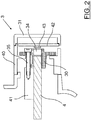
- the coded zoom knob 3 comprises a rotor 30 and a stator 40.
- the rotor 30 is rotatable around a central longitudinal axis in relation to the fixed stator 40.
- the rotor 30 comprises a central screw 35 by which the coded zoom knob is fitted in a screw joint mode to an adaptor member 41 of the housing 7 of the microscope 1. Further, the rotor 30 comprises a magnet 34 in line with the zoom drive shaft 4.
- the stator 40 comprises a magnetic sensor 43, like a well-known Hall effect sensor, and, in the embodiment shown in Figure 2 , an electronic assembly 42 that allows determination of the rotary position of the magnet 34 in relation to the magnetic sensor 43 and thus calculation of a magnification information of the zoom system 10.
- the magnetic sensor 43 and the electronic assembly 42 are stationary and fixed to the stator 40.
- the stator 40 comprises an outer housing including a cap 31 formed to be mounted to the housing 7 of the microscope 1 at a position of a removed non-coded zoom knob (see zoom knob 2 of Figure 1 ). As can be seen from Figure 2 , the outer housing including the cap 31 encompasses the other elements of the coded zoom knob 3.
- FIG. 2 another embodiment is possible where the rotor 30 with the zoom drive shaft 4 is connected to a cap 31 such that by rotating the cap 31 the zoom drive shaft 4 can be operated by an operator.
- the magnetic sensor 43 would have to be connected to the fixed stator 40 such that the magnetic sensor 43 is able to detect a rotation of the magnet 34.
- the electronic assembly 42 could also be place into the stator 40 but also, in principle, into the cap 31 if the magnetic sensor 43 and the electronic assembly 42 communicate wirelessly.
Landscapes
- Physics & Mathematics (AREA)
- Chemical & Material Sciences (AREA)
- Analytical Chemistry (AREA)
- General Physics & Mathematics (AREA)
- Optics & Photonics (AREA)
- Microscoopes, Condenser (AREA)
- Lens Barrels (AREA)
Abstract
Description
- The present invention relates to a coded zoom knob, a microscope having the same and a method for retrofitting a microscope with a coded zoom knob. The invention further relates to a method for operating such a microscope.
- Microscopes having zoom systems allowing a continuously adjustable magnification of objects to be observed are widely know in the prior art. The range of magnification provided by the zoom system can be characterized by a so-called zoom factor or magnification factor of the zoom system. When imaging an object, especially by using a camera, it is useful to know the respective magnification of the zoom system. Especially, it is advantageous to track the current magnification and save the magnification information together with the image generated by the camera. This is especially advantageous if microscope images of the same object are to be taken and compared at different points of time. High end microscopes such as high performance stereo microscopes usually comprise coded zoom systems where the rotation of the threaded spindle carrying the movable zoom lenses is detected and coded for providing the current magnification of the zoom system. The coded rotation of the threaded spindle corresponds to the magnification of the zoom system, which can be determined and saved and/or displayed together with the microscopic image. Such microscopes allow reproducible and comparable microscopic images.
- However, less expensive zoom microscopes are not equipped with such a zoom coding system and up to now it is not possible to exchange zoom coding systems or to retrofit a microscope with such a zoom coding system. Such zoom microscopes typically comprise a zoom system driven by a zoom drive shaft which shaft is usually operated manually by a user of the microscope by rotating a zoom knob. Typically, two such zoom knobs are mounted on the left and on the right side of the zoom drive shaft axis of the microscope housing. By rotating one of said zoom knobs, the zoom drive shaft is rotated resulting in a movement of the movable lenses of the zoom system such that the magnification of the zoom system can be varied.
- To overcome the drawbacks of the prior art, the present invention provides a coded zoom knob, a microscope having such a coded zoom knob and a method for retrofitting a microscope according to the independent claims. Further, a method for operating such a microscope is provided. Advantageous embodiments are the subject matter of the dependent claims and the following description.
- According to a first aspect of the present invention, a coded zoom knob for detecting the rotation of a zoom drive shaft of a zoom system of a microscope is provided. The coded zoom knob comprises a stator and a rotor rotatable in relation to the stator, the rotor being adapted to be mounted to the zoom drive shaft, and the stator comprising a rotation sensor for sensing a rotation of the rotor. The coded zoom knob according to the present invention comprises at least the elements necessary to sense or detect a rotation of the zoom drive shaft which itself drives the zoom system for varying the magnification of the zoom system. It should be noted that the coded zoom knob does not necessarily drive the zoom drive shaft, i.e. the coded zoom knob itself is preferably not rotatable. It is preferred that the zoom drive shaft is driven by a conventional zoom knob. The coded zoom knob according to the present invention is easily retrofittable to a conventional microscope having two zoom knobs, one at each end of the zoom drive shaft axis on the left and on the right side of the microscope housing, by replacing one of said conventional zoom knobs with a coded zoom knob.
- According to a second aspect of the present invention, a method for retrofitting a microscope with a coded zoom knob according to the present invention is provided. Said microscope comprises at least one zoom knob for driving a zoom drive shaft of a zoom system of the microscope. The coded zoom knob comprises a stator and a rotor rotatable in relation to the stator, the stator comprising a rotation sensor for sensing a rotation of the rotor. The microscope is retrofitted with such a coded zoom knob by the steps of replacing one zoom knob for driving the zoom drive shaft by the coded zoom knob according to the present invention. Replacing one zoom knob by the coded zoom knob includes removing said one zoom knob, fitting the rotor of the coded zoom knob on the zoom drive shaft of the zoom system and fitting the stator of the coded zoom knob on a housing of the microscope.
- According to a third aspect of the present invention, a microscope is provided comprising a zoom system, a zoom drive shaft for driving the zoom system, a zoom knob for operating or driving the zoom drive shaft and the coded zoom knob according to the present invention.
- According to a fourth aspect of the present invention, a method for operating a microscope is provided which microscope comprises a coded zoom knob having an electronic assembly adapted to track or calculate a magnification information, such as a magnification or a parameter corresponding to the magnification, of the zoom system of the microscope on the basis of the determined rotation of the rotor. In this method, the magnification information of the zoom system is used to control an aperture of an illuminating beam path of the microscope.
- By constructing the coded zoom knob as a separate component adapted to replace a conventional rotary zoom knob it can be mounted to a microscope that is not serially equipped with a zoom coding system. Such zoom microscopes usually comprise a zoom drive shaft mounted orthogonally to the zoom axis for driving the zoom system, i.e. for adjusting the positions of the lens groups of the zoom system. With the present invention, one of the original zoom knobs can be replaced by a coded zoom knob for coding the zoom magnification.
- Preferably, the rotor comprises a magnet, while the stator comprises a magnet sensor as the rotation sensor. For the ease of illustration, in the following - without any limitation of the scope of protection - it is to be understood that the rotor comprises a magnet, while the stator comprises a magnet sensor like a Hall effect sensor.
- The retrofitted coded zoom knob allows tracking the rotary position of the rotor in relation to the fixed stator and, thus, to track the adjusted zoom magnification.
- In a preferred embodiment, the stator comprises an electronic assembly adapted to determine a rotation of the rotor in relation to the stator and, preferably, to track and/or to calculate a magnification information of the zoom system of the microscope on the basis of the determined rotation. The magnification information can, for example, be the current magnification itself or a value proportional to the magnification of the zoom system. It is advantageous if the electronic assembly is part of the fixed stator which is connected to the stationary housing of the microscope. The electronic assembly is preferably connected with a control unit and/or with a camera of the microscope. By receiving the output signal from the magnetic sensor, the electronic assembly can determine the rotary position of the rotor and calculate the magnification on the basis of the determined rotary position. It is also possible to dispose the electronic assembly outside the coded rotary zoom knob, i.e. inside a housing of the microscope, or even outside of the microscope housing. Signals can be transferred between the electronic assembly and the magnetic sensor via signal lines or in a wireless fashion. Same applies to the signals transferred between the electronic assembly and the control unit or the camera of the microscope.
- In a preferred embodiment, the stator is adapted to be fitted on a housing of the microscope, especially on the zoom drive shaft axis of the microscope housing. The coded zoom knob can be of a similar design as the non-coded conventional zoom knob on the other side of the zoom drive shaft axis.
- In a further preferred embodiment, the stator comprises a cap such that the cap forms a first axial end of the coded zoom knob and of the zoom drive shaft axis of the microscope housing.
- In a preferred embodiment, the rotor comprises a central screw for mounting the rotor together with the coded zoom knob to the housing of the microscope. This allows an easy retrofitting of a coded zoom knob by connecting the rotor of the coded zoom knob with the microscope housing by a screw joint. It is advantageous if the microscope housing comprises an adapter member adapted to be connected with the central screw of the rotor of the coded zoom knob. The adapter member is especially formed in a way to be mounted to the microscope housing at a position where the original zoom knob was removed.
- Preferably, the outside of the stator (together with the stator cap) encompasses all elements of the coded zoom knob as will be further described in connection with an embodiment of the present invention shown in the appended figures.
- As already mentioned before, the coded zoom knob is retrofitted at either one of the two axial ends of the zoom drive shaft The zoom drive shaft of a microscope comprises two axial ends at two lateral sides of the microscope. In this way, an operator may choose on which lateral side of the microscope he/she wants to retrofit the coded zoom knob.
- According to still another aspect of the present invention, a microscope is provided comprising a coded zoom knob retrofitted to the microscope according to a method according to the present invention.
- Finally, a method for operating a microscope according to the present invention is provided, wherein a magnification information of the zoom system is used to control an aperture of an illuminating beam path of the microscope. A magnification information can be tracked or even calculated by an electronic assembly as described above in relation to the method according to the invention. Usually, the higher the magnification of the microscope, the more light is needed in the illuminating beam path in order to achieve an image of sufficient brightness. As the magnification of the zoom microscope can be tracked by the retrofitted coded zoom knob, the corresponding magnification information can be advantageously used to control an illumination aperture of the microscope.
- Further embodiments and advantages of the claimed invention become apparent from the attached figures in combination with the following description.
- Figure 1
- shows in a schematic way a microscope with a retrofitted coded zoom knob,and
- Figure 2
- shows an enlarged view of the retrofitted coded zoom knob of
Figure 1 . -
Figure 1 schematically shows amicroscope 1 comprising a housing 7, azoom system 10 and an objective 11. The sample or object to be imaged by the microscope is designated 6. The positions of a part of thelens groups 8, 9 of thezoom system 10 can be adjusted by a threadedspindle 5 along the zoom axis. The threadedspindle 5 itself is driven by thezoom drive shaft 4. - As can be seen from
Figure 1 , themicroscope 1 has a non-codedconventional zoom knob 2 and a retrofittedcoded zoom knob 3. Thenon-coded zoom knob 2 can be rotated by an operator of themicroscope 1. By rotating thezoom knob 2, thezoom drive shaft 4 is rotated, which rotation results in a rotation of the threadedspindle 5 carrying the movable lens groups of thezoom system 10. A movement of one or more of thelens groups 8, 9 (depending on the type of the zoom system) results in a variation of the zoom magnification. The zoom magnification is therefore a function of the rotation of thezoom drive shaft 4. Thus, a magnification information can be derived from a determined rotation of thezoom drive shaft 4. To this purpose, acoded zoom knob 3 is retrofitted to themicroscope 1. - Details of the retrofitted coded
zoom knob 3 are shown inFigure 2 . - The
coded zoom knob 3 comprises arotor 30 and astator 40. Therotor 30 is rotatable around a central longitudinal axis in relation to the fixedstator 40. Therotor 30 comprises acentral screw 35 by which the coded zoom knob is fitted in a screw joint mode to anadaptor member 41 of the housing 7 of themicroscope 1. Further, therotor 30 comprises amagnet 34 in line with thezoom drive shaft 4. - The
stator 40 comprises amagnetic sensor 43, like a well-known Hall effect sensor, and, in the embodiment shown inFigure 2 , anelectronic assembly 42 that allows determination of the rotary position of themagnet 34 in relation to themagnetic sensor 43 and thus calculation of a magnification information of thezoom system 10. Themagnetic sensor 43 and theelectronic assembly 42 are stationary and fixed to thestator 40. Furthermore, thestator 40 comprises an outer housing including acap 31 formed to be mounted to the housing 7 of themicroscope 1 at a position of a removed non-coded zoom knob (seezoom knob 2 ofFigure 1 ). As can be seen fromFigure 2 , the outer housing including thecap 31 encompasses the other elements of the codedzoom knob 3. - As can be seen from
Figure 2 , another embodiment is possible where therotor 30 with thezoom drive shaft 4 is connected to acap 31 such that by rotating thecap 31 thezoom drive shaft 4 can be operated by an operator. In this case, at least themagnetic sensor 43 would have to be connected to the fixedstator 40 such that themagnetic sensor 43 is able to detect a rotation of themagnet 34. Theelectronic assembly 42 could also be place into thestator 40 but also, in principle, into thecap 31 if themagnetic sensor 43 and theelectronic assembly 42 communicate wirelessly. -
- 1
- microscope
- 2
- non-coded zoom knob
- 3
- coded zoom knob
- 4
- zoom drive shaft
- 5
- threaded spindle
- 6
- sample
- 7
- housing
- 8
- lens group
- 9
- lens group
- 10
- zoom system
- 11
- objective
- 30
- rotor
- 31
- cap
- 34
- magnet
- 35
- screw
- 40
- stator
- 41
- adapter member
- 42
- electronic assembly
- 43
- magnetic sensor
Claims (13)
- A coded zoom knob (3) for detecting the rotation of a zoom drive shaft (4) of a zoom system (10) of a microscope (1), comprising
a stator (40) and a rotor (30) rotatable in relation to the stator (40),
the rotor (30) being adapted to be mounted to the zoom drive shaft (4), and
the stator (40) comprising a rotation sensor (43) for sensing a rotation of the rotor (30). - The coded zoom knob (3) of claim 1, wherein the rotor (30) comprises a magnet (34) and the stator (40) comprises a magnet sensor (43) as the rotation sensor.
- The coded zoom knob of claim 1 or 2, wherein the stator (45) comprises an electronic assembly (42) operationally connected to the rotation sensor (43), said electronic assembly (42) being adapted to track a magnification information of the zoom system (10) of the microscope (1) on the basis of the determined rotation of the rotor (30).
- The coded zoom knob (3) of claim 3, wherein the electronic assembly (42) is further adapted to calculate the magnification information of the zoom system (10) of the microscope (1) on the basis of the determined rotation of the rotor (30).
- The coded zoom knob of any one of the preceding claims, wherein the stator (40) is adapted to be fitted on a housing (7) of the microscope (1).
- The coded zoom knob (3) of claim 5, wherein the stator (40) is adapted to be fitted on the zoom drive shaft axis of the microscope housing (7).
- The coded zoom knob (3) of claim 6, wherein the stator (40) comprises a cap (31) forming a first axial end of the zoom drive shaft axis of the microscope housing (7).
- The coded zoom knob (3) of any one of the preceding claims, wherein the rotor (30) comprises a central screw (35) for mounting the coded zoom knob (3) to the housing (7) of the microscope (1).
- A microscope (1) comprising
a zoom system (10),
a zoom drive shaft (4) for driving the zoom system (10),
a zoom knob (2) for operating the zoom drive shaft (4), and
the coded zoom knob (3) of any one of the claims 1 to 8. - The microscope of claim 9 having the coded zoom knob of claim 8, wherein the microscope housing (7) comprises an adapter member (41) being adapted to be connected with the central screw (35) of the rotor (30) of the coded zoom knob (3).
- A method for retrofitting a microscope (1) with a coded zoom knob (3), said microscope (1) having at least one zoom knob (2) for driving a zoom drive shaft (4) of a zoom system (10) of the microscope (1), the coded zoom knob (3) having a stator (40) and a rotor (30) rotatable in relation to the stator (40), the stator (40) comprising a rotation sensor (43) for sensing a rotation of the rotor (30), comprising the steps of
replacing one zoom knob (2) by the coded zoom knob (3) by removing said one zoom knob (2),
fitting the rotor (30) of the coded zoom knob (3) on the zoom drive shaft (4) of the zoom system (10), and
fitting the stator (40) of the coded zoom knob (3) on a housing (7) of the microscope (1). - The method of claim 11, wherein the coded zoom knob (3) is mounted to the housing (7) of the microscope (1) by connecting an adaptor member (41) of the microscope housing (7) with a central screw (35) provided in the rotor (30) of the coded zoom knob (3).
- A method for operating a microscope (1) according to claim 9 or 10, having a coded zoom knob (3) of claim 3 or 4, wherein the magnification information of the zoom system (10) is used to control an aperture of an illuminating beam path of the microscope (1).
Priority Applications (5)
| Application Number | Priority Date | Filing Date | Title |
|---|---|---|---|
| EP17158143.2A EP3367153B1 (en) | 2017-02-27 | 2017-02-27 | Coded zoom knob, microscope having the same and method for retrofitting a coded zoom knob |
| US15/895,338 US10816785B2 (en) | 2017-02-27 | 2018-02-13 | Coded zoom knob, microscope having the same and method for retrofitting a coded zoom knob |
| JP2018031897A JP6574006B2 (en) | 2017-02-27 | 2018-02-26 | Encoding zoom knob, microscope having encoding zoom knob, and method of incorporating encoding zoom knob |
| CN201810161256.9A CN108508587B (en) | 2017-02-27 | 2018-02-26 | Coded zoom knob, microscope having a coded zoom knob and method of retrofitting a coded zoom knob |
| US17/005,864 US11460681B2 (en) | 2017-02-27 | 2020-08-28 | Coded zoom knob, microscope having the same and method for retrofitting a coded zoom knob |
Applications Claiming Priority (1)
| Application Number | Priority Date | Filing Date | Title |
|---|---|---|---|
| EP17158143.2A EP3367153B1 (en) | 2017-02-27 | 2017-02-27 | Coded zoom knob, microscope having the same and method for retrofitting a coded zoom knob |
Publications (2)
| Publication Number | Publication Date |
|---|---|
| EP3367153A1 true EP3367153A1 (en) | 2018-08-29 |
| EP3367153B1 EP3367153B1 (en) | 2022-02-09 |
Family
ID=58185414
Family Applications (1)
| Application Number | Title | Priority Date | Filing Date |
|---|---|---|---|
| EP17158143.2A Active EP3367153B1 (en) | 2017-02-27 | 2017-02-27 | Coded zoom knob, microscope having the same and method for retrofitting a coded zoom knob |
Country Status (4)
| Country | Link |
|---|---|
| US (2) | US10816785B2 (en) |
| EP (1) | EP3367153B1 (en) |
| JP (1) | JP6574006B2 (en) |
| CN (1) | CN108508587B (en) |
Citations (2)
| Publication number | Priority date | Publication date | Assignee | Title |
|---|---|---|---|---|
| EP1746450A1 (en) * | 2005-07-19 | 2007-01-24 | Olympus Corporation | Zoom microscope |
| US20080144168A1 (en) * | 2006-12-14 | 2008-06-19 | Leica Microsystems (Schweiz) Ag | Microscope Having A Sensor Operating In Non-Contact Fashion |
Family Cites Families (12)
| Publication number | Priority date | Publication date | Assignee | Title |
|---|---|---|---|---|
| US5396063A (en) * | 1992-06-08 | 1995-03-07 | Nikon Corporation | Objective replacing apparatus having objective position, displacement and address detecting means and microscope using it |
| JP3447357B2 (en) * | 1994-03-11 | 2003-09-16 | オリンパス光学工業株式会社 | Microscope system |
| US5825531A (en) * | 1994-12-14 | 1998-10-20 | Nikon Corporation | Electrical moving apparatus for microscope |
| US6384967B1 (en) * | 1998-09-11 | 2002-05-07 | Olympus Optical Co., Ltd. | Illumination apparatus for a microscope |
| DE10135511C1 (en) * | 2001-07-20 | 2003-04-17 | Leica Microsystems | Device and method for adjusting components of an optical or mechanical system |
| US20050094262A1 (en) * | 2003-11-05 | 2005-05-05 | Visx, Incorporated | Microscope magnification sensor |
| JP2009186728A (en) | 2008-02-06 | 2009-08-20 | Sony Corp | Video microscope and observation adapter |
| CN104216102A (en) | 2013-06-02 | 2014-12-17 | 麦克奥迪实业集团有限公司 | Position identification device of telescope |
| DE102013012988A1 (en) * | 2013-08-03 | 2015-02-05 | Carl Zeiss Microscopy Gmbh | A method of calibrating a digital optical imaging system, a method of correcting aberrations in a digital optical imaging system, and a digital optical imaging system |
| CN106461928B (en) * | 2014-06-10 | 2019-09-17 | 奥林巴斯株式会社 | Image processing apparatus, photographic device, microscopic system and image processing method |
| EP3197146B1 (en) * | 2014-09-19 | 2023-09-06 | Sony Group Corporation | Medical observation device and lens tube for medical observation device |
| CN204883037U (en) | 2015-07-01 | 2015-12-16 | 苏勋涛 | Microscope focusing ware based on supersound motor drive |
-
2017
- 2017-02-27 EP EP17158143.2A patent/EP3367153B1/en active Active
-
2018
- 2018-02-13 US US15/895,338 patent/US10816785B2/en active Active
- 2018-02-26 CN CN201810161256.9A patent/CN108508587B/en active Active
- 2018-02-26 JP JP2018031897A patent/JP6574006B2/en active Active
-
2020
- 2020-08-28 US US17/005,864 patent/US11460681B2/en active Active
Patent Citations (2)
| Publication number | Priority date | Publication date | Assignee | Title |
|---|---|---|---|---|
| EP1746450A1 (en) * | 2005-07-19 | 2007-01-24 | Olympus Corporation | Zoom microscope |
| US20080144168A1 (en) * | 2006-12-14 | 2008-06-19 | Leica Microsystems (Schweiz) Ag | Microscope Having A Sensor Operating In Non-Contact Fashion |
Also Published As
| Publication number | Publication date |
|---|---|
| US20200393663A1 (en) | 2020-12-17 |
| US11460681B2 (en) | 2022-10-04 |
| US10816785B2 (en) | 2020-10-27 |
| JP6574006B2 (en) | 2019-09-11 |
| CN108508587A (en) | 2018-09-07 |
| JP2018141973A (en) | 2018-09-13 |
| US20180246310A1 (en) | 2018-08-30 |
| CN108508587B (en) | 2021-02-02 |
| EP3367153B1 (en) | 2022-02-09 |
Similar Documents
| Publication | Publication Date | Title |
|---|---|---|
| US10330906B2 (en) | Imaging assemblies with rapid sample auto-focusing | |
| JP6562627B2 (en) | Microscope system | |
| JP6560490B2 (en) | Microscope system | |
| US8860827B2 (en) | Zoom lens apparatus and image pickup system having an image stabilzer with a lens positional deviation control, and operation unit thereof | |
| US8374497B2 (en) | Autofocusing zoom lens | |
| CN103080805A (en) | Camera system, and lens barrel | |
| CN116819749A (en) | Electric microscope objective lens converter, high-precision positioning method thereof and microscope | |
| US9148559B2 (en) | Device for assisting focusing of a camera | |
| US11460681B2 (en) | Coded zoom knob, microscope having the same and method for retrofitting a coded zoom knob | |
| CN101206307B (en) | Microscope having a sensor operating in non-contact fashion | |
| US10088654B2 (en) | Lens device and correction method for lens device | |
| US10863892B2 (en) | Imaging device and endoscope system | |
| US7380943B2 (en) | Method and arrangement for determining the adjusted magnification step in ophthalmologic instruments, particularly slit lamps | |
| JP2006078638A (en) | Optical equipment | |
| EP1631061B1 (en) | Image-capturing apparatus and driving method for an optical system | |
| KR101770909B1 (en) | Image sensor apparatus for changing multi-lens automatically | |
| JP4993587B2 (en) | Automatic lens magnification recognition device for optical equipment | |
| WO2017170698A1 (en) | Adapter, microscope adjustment method, microscope system and program | |
| WO2017072927A1 (en) | Optical system and endoscopic system | |
| JP5125259B2 (en) | LENS DRIVE DEVICE, LENS DRIVE METHOD, FOCUS ADJUSTMENT DEVICE, AND IMAGING DEVICE | |
| JPH08184740A (en) | microscope | |
| CN111031892A (en) | Device for adjusting the magnification level of a zoom driven by an actuator | |
| JP2009008985A (en) | Focus adjustment device and imaging device | |
| JP5428832B2 (en) | Handle device, optical equipment | |
| JP2017219661A (en) | Lens device |
Legal Events
| Date | Code | Title | Description |
|---|---|---|---|
| PUAI | Public reference made under article 153(3) epc to a published international application that has entered the european phase |
Free format text: ORIGINAL CODE: 0009012 |
|
| STAA | Information on the status of an ep patent application or granted ep patent |
Free format text: STATUS: THE APPLICATION HAS BEEN PUBLISHED |
|
| AK | Designated contracting states |
Kind code of ref document: A1 Designated state(s): AL AT BE BG CH CY CZ DE DK EE ES FI FR GB GR HR HU IE IS IT LI LT LU LV MC MK MT NL NO PL PT RO RS SE SI SK SM TR |
|
| AX | Request for extension of the european patent |
Extension state: BA ME |
|
| STAA | Information on the status of an ep patent application or granted ep patent |
Free format text: STATUS: REQUEST FOR EXAMINATION WAS MADE |
|
| 17P | Request for examination filed |
Effective date: 20190213 |
|
| RBV | Designated contracting states (corrected) |
Designated state(s): AL AT BE BG CH CY CZ DE DK EE ES FI FR GB GR HR HU IE IS IT LI LT LU LV MC MK MT NL NO PL PT RO RS SE SI SK SM TR |
|
| STAA | Information on the status of an ep patent application or granted ep patent |
Free format text: STATUS: EXAMINATION IS IN PROGRESS |
|
| 17Q | First examination report despatched |
Effective date: 20200129 |
|
| GRAP | Despatch of communication of intention to grant a patent |
Free format text: ORIGINAL CODE: EPIDOSNIGR1 |
|
| STAA | Information on the status of an ep patent application or granted ep patent |
Free format text: STATUS: GRANT OF PATENT IS INTENDED |
|
| INTG | Intention to grant announced |
Effective date: 20210824 |
|
| GRAS | Grant fee paid |
Free format text: ORIGINAL CODE: EPIDOSNIGR3 |
|
| GRAA | (expected) grant |
Free format text: ORIGINAL CODE: 0009210 |
|
| STAA | Information on the status of an ep patent application or granted ep patent |
Free format text: STATUS: THE PATENT HAS BEEN GRANTED |
|
| AK | Designated contracting states |
Kind code of ref document: B1 Designated state(s): AL AT BE BG CH CY CZ DE DK EE ES FI FR GB GR HR HU IE IS IT LI LT LU LV MC MK MT NL NO PL PT RO RS SE SI SK SM TR |
|
| REG | Reference to a national code |
Ref country code: GB Ref legal event code: FG4D |
|
| REG | Reference to a national code |
Ref country code: CH Ref legal event code: EP Ref country code: AT Ref legal event code: REF Ref document number: 1467859 Country of ref document: AT Kind code of ref document: T Effective date: 20220215 |
|
| REG | Reference to a national code |
Ref country code: DE Ref legal event code: R096 Ref document number: 602017053086 Country of ref document: DE |
|
| REG | Reference to a national code |
Ref country code: IE Ref legal event code: FG4D |
|
| REG | Reference to a national code |
Ref country code: LT Ref legal event code: MG9D |
|
| REG | Reference to a national code |
Ref country code: NL Ref legal event code: MP Effective date: 20220209 |
|
| REG | Reference to a national code |
Ref country code: AT Ref legal event code: MK05 Ref document number: 1467859 Country of ref document: AT Kind code of ref document: T Effective date: 20220209 |
|
| PG25 | Lapsed in a contracting state [announced via postgrant information from national office to epo] |
Ref country code: SE Free format text: LAPSE BECAUSE OF FAILURE TO SUBMIT A TRANSLATION OF THE DESCRIPTION OR TO PAY THE FEE WITHIN THE PRESCRIBED TIME-LIMIT Effective date: 20220209 Ref country code: RS Free format text: LAPSE BECAUSE OF FAILURE TO SUBMIT A TRANSLATION OF THE DESCRIPTION OR TO PAY THE FEE WITHIN THE PRESCRIBED TIME-LIMIT Effective date: 20220209 Ref country code: PT Free format text: LAPSE BECAUSE OF FAILURE TO SUBMIT A TRANSLATION OF THE DESCRIPTION OR TO PAY THE FEE WITHIN THE PRESCRIBED TIME-LIMIT Effective date: 20220609 Ref country code: NO Free format text: LAPSE BECAUSE OF FAILURE TO SUBMIT A TRANSLATION OF THE DESCRIPTION OR TO PAY THE FEE WITHIN THE PRESCRIBED TIME-LIMIT Effective date: 20220509 Ref country code: NL Free format text: LAPSE BECAUSE OF FAILURE TO SUBMIT A TRANSLATION OF THE DESCRIPTION OR TO PAY THE FEE WITHIN THE PRESCRIBED TIME-LIMIT Effective date: 20220209 Ref country code: LT Free format text: LAPSE BECAUSE OF FAILURE TO SUBMIT A TRANSLATION OF THE DESCRIPTION OR TO PAY THE FEE WITHIN THE PRESCRIBED TIME-LIMIT Effective date: 20220209 Ref country code: HR Free format text: LAPSE BECAUSE OF FAILURE TO SUBMIT A TRANSLATION OF THE DESCRIPTION OR TO PAY THE FEE WITHIN THE PRESCRIBED TIME-LIMIT Effective date: 20220209 Ref country code: ES Free format text: LAPSE BECAUSE OF FAILURE TO SUBMIT A TRANSLATION OF THE DESCRIPTION OR TO PAY THE FEE WITHIN THE PRESCRIBED TIME-LIMIT Effective date: 20220209 Ref country code: BG Free format text: LAPSE BECAUSE OF FAILURE TO SUBMIT A TRANSLATION OF THE DESCRIPTION OR TO PAY THE FEE WITHIN THE PRESCRIBED TIME-LIMIT Effective date: 20220509 |
|
| PG25 | Lapsed in a contracting state [announced via postgrant information from national office to epo] |
Ref country code: PL Free format text: LAPSE BECAUSE OF FAILURE TO SUBMIT A TRANSLATION OF THE DESCRIPTION OR TO PAY THE FEE WITHIN THE PRESCRIBED TIME-LIMIT Effective date: 20220209 Ref country code: LV Free format text: LAPSE BECAUSE OF FAILURE TO SUBMIT A TRANSLATION OF THE DESCRIPTION OR TO PAY THE FEE WITHIN THE PRESCRIBED TIME-LIMIT Effective date: 20220209 Ref country code: GR Free format text: LAPSE BECAUSE OF FAILURE TO SUBMIT A TRANSLATION OF THE DESCRIPTION OR TO PAY THE FEE WITHIN THE PRESCRIBED TIME-LIMIT Effective date: 20220510 Ref country code: FI Free format text: LAPSE BECAUSE OF FAILURE TO SUBMIT A TRANSLATION OF THE DESCRIPTION OR TO PAY THE FEE WITHIN THE PRESCRIBED TIME-LIMIT Effective date: 20220209 Ref country code: AT Free format text: LAPSE BECAUSE OF FAILURE TO SUBMIT A TRANSLATION OF THE DESCRIPTION OR TO PAY THE FEE WITHIN THE PRESCRIBED TIME-LIMIT Effective date: 20220209 |
|
| PG25 | Lapsed in a contracting state [announced via postgrant information from national office to epo] |
Ref country code: IS Free format text: LAPSE BECAUSE OF FAILURE TO SUBMIT A TRANSLATION OF THE DESCRIPTION OR TO PAY THE FEE WITHIN THE PRESCRIBED TIME-LIMIT Effective date: 20220609 |
|
| REG | Reference to a national code |
Ref country code: CH Ref legal event code: PL |
|
| REG | Reference to a national code |
Ref country code: BE Ref legal event code: MM Effective date: 20220228 |
|
| PG25 | Lapsed in a contracting state [announced via postgrant information from national office to epo] |
Ref country code: SM Free format text: LAPSE BECAUSE OF FAILURE TO SUBMIT A TRANSLATION OF THE DESCRIPTION OR TO PAY THE FEE WITHIN THE PRESCRIBED TIME-LIMIT Effective date: 20220209 Ref country code: SK Free format text: LAPSE BECAUSE OF FAILURE TO SUBMIT A TRANSLATION OF THE DESCRIPTION OR TO PAY THE FEE WITHIN THE PRESCRIBED TIME-LIMIT Effective date: 20220209 Ref country code: RO Free format text: LAPSE BECAUSE OF FAILURE TO SUBMIT A TRANSLATION OF THE DESCRIPTION OR TO PAY THE FEE WITHIN THE PRESCRIBED TIME-LIMIT Effective date: 20220209 Ref country code: LU Free format text: LAPSE BECAUSE OF NON-PAYMENT OF DUE FEES Effective date: 20220227 Ref country code: EE Free format text: LAPSE BECAUSE OF FAILURE TO SUBMIT A TRANSLATION OF THE DESCRIPTION OR TO PAY THE FEE WITHIN THE PRESCRIBED TIME-LIMIT Effective date: 20220209 Ref country code: DK Free format text: LAPSE BECAUSE OF FAILURE TO SUBMIT A TRANSLATION OF THE DESCRIPTION OR TO PAY THE FEE WITHIN THE PRESCRIBED TIME-LIMIT Effective date: 20220209 Ref country code: CZ Free format text: LAPSE BECAUSE OF FAILURE TO SUBMIT A TRANSLATION OF THE DESCRIPTION OR TO PAY THE FEE WITHIN THE PRESCRIBED TIME-LIMIT Effective date: 20220209 |
|
| REG | Reference to a national code |
Ref country code: DE Ref legal event code: R097 Ref document number: 602017053086 Country of ref document: DE |
|
| PG25 | Lapsed in a contracting state [announced via postgrant information from national office to epo] |
Ref country code: MC Free format text: LAPSE BECAUSE OF FAILURE TO SUBMIT A TRANSLATION OF THE DESCRIPTION OR TO PAY THE FEE WITHIN THE PRESCRIBED TIME-LIMIT Effective date: 20220209 Ref country code: AL Free format text: LAPSE BECAUSE OF FAILURE TO SUBMIT A TRANSLATION OF THE DESCRIPTION OR TO PAY THE FEE WITHIN THE PRESCRIBED TIME-LIMIT Effective date: 20220209 |
|
| PLBE | No opposition filed within time limit |
Free format text: ORIGINAL CODE: 0009261 |
|
| STAA | Information on the status of an ep patent application or granted ep patent |
Free format text: STATUS: NO OPPOSITION FILED WITHIN TIME LIMIT |
|
| 26N | No opposition filed |
Effective date: 20221110 |
|
| PG25 | Lapsed in a contracting state [announced via postgrant information from national office to epo] |
Ref country code: LI Free format text: LAPSE BECAUSE OF NON-PAYMENT OF DUE FEES Effective date: 20220228 Ref country code: IE Free format text: LAPSE BECAUSE OF NON-PAYMENT OF DUE FEES Effective date: 20220227 Ref country code: CH Free format text: LAPSE BECAUSE OF NON-PAYMENT OF DUE FEES Effective date: 20220228 |
|
| PG25 | Lapsed in a contracting state [announced via postgrant information from national office to epo] |
Ref country code: SI Free format text: LAPSE BECAUSE OF FAILURE TO SUBMIT A TRANSLATION OF THE DESCRIPTION OR TO PAY THE FEE WITHIN THE PRESCRIBED TIME-LIMIT Effective date: 20220209 Ref country code: BE Free format text: LAPSE BECAUSE OF NON-PAYMENT OF DUE FEES Effective date: 20220228 |
|
| P01 | Opt-out of the competence of the unified patent court (upc) registered |
Effective date: 20230414 |
|
| PG25 | Lapsed in a contracting state [announced via postgrant information from national office to epo] |
Ref country code: IT Free format text: LAPSE BECAUSE OF FAILURE TO SUBMIT A TRANSLATION OF THE DESCRIPTION OR TO PAY THE FEE WITHIN THE PRESCRIBED TIME-LIMIT Effective date: 20220209 |
|
| PG25 | Lapsed in a contracting state [announced via postgrant information from national office to epo] |
Ref country code: HU Free format text: LAPSE BECAUSE OF FAILURE TO SUBMIT A TRANSLATION OF THE DESCRIPTION OR TO PAY THE FEE WITHIN THE PRESCRIBED TIME-LIMIT; INVALID AB INITIO Effective date: 20170227 |
|
| PG25 | Lapsed in a contracting state [announced via postgrant information from national office to epo] |
Ref country code: MK Free format text: LAPSE BECAUSE OF FAILURE TO SUBMIT A TRANSLATION OF THE DESCRIPTION OR TO PAY THE FEE WITHIN THE PRESCRIBED TIME-LIMIT Effective date: 20220209 Ref country code: CY Free format text: LAPSE BECAUSE OF FAILURE TO SUBMIT A TRANSLATION OF THE DESCRIPTION OR TO PAY THE FEE WITHIN THE PRESCRIBED TIME-LIMIT Effective date: 20220209 |
|
| PG25 | Lapsed in a contracting state [announced via postgrant information from national office to epo] |
Ref country code: MT Free format text: LAPSE BECAUSE OF FAILURE TO SUBMIT A TRANSLATION OF THE DESCRIPTION OR TO PAY THE FEE WITHIN THE PRESCRIBED TIME-LIMIT Effective date: 20220209 |
|
| PG25 | Lapsed in a contracting state [announced via postgrant information from national office to epo] |
Ref country code: TR Free format text: LAPSE BECAUSE OF FAILURE TO SUBMIT A TRANSLATION OF THE DESCRIPTION OR TO PAY THE FEE WITHIN THE PRESCRIBED TIME-LIMIT Effective date: 20220209 |
|
| PGFP | Annual fee paid to national office [announced via postgrant information from national office to epo] |
Ref country code: GB Payment date: 20260223 Year of fee payment: 10 |
|
| PGFP | Annual fee paid to national office [announced via postgrant information from national office to epo] |
Ref country code: DE Payment date: 20260220 Year of fee payment: 10 |
|
| PGFP | Annual fee paid to national office [announced via postgrant information from national office to epo] |
Ref country code: FR Payment date: 20260227 Year of fee payment: 10 |