EP3366876A1 - Fireproof sliding door and window - Google Patents
Fireproof sliding door and window Download PDFInfo
- Publication number
- EP3366876A1 EP3366876A1 EP16857577.7A EP16857577A EP3366876A1 EP 3366876 A1 EP3366876 A1 EP 3366876A1 EP 16857577 A EP16857577 A EP 16857577A EP 3366876 A1 EP3366876 A1 EP 3366876A1
- Authority
- EP
- European Patent Office
- Prior art keywords
- thermally expandable
- frame
- resistant material
- fire
- layer
- Prior art date
- Legal status (The legal status is an assumption and is not a legal conclusion. Google has not performed a legal analysis and makes no representation as to the accuracy of the status listed.)
- Withdrawn
Links
Images


Classifications
-
- E—FIXED CONSTRUCTIONS
- E06—DOORS, WINDOWS, SHUTTERS, OR ROLLER BLINDS IN GENERAL; LADDERS
- E06B—FIXED OR MOVABLE CLOSURES FOR OPENINGS IN BUILDINGS, VEHICLES, FENCES OR LIKE ENCLOSURES IN GENERAL, e.g. DOORS, WINDOWS, BLINDS, GATES
- E06B5/00—Doors, windows, or like closures for special purposes; Border constructions therefor
- E06B5/10—Doors, windows, or like closures for special purposes; Border constructions therefor for protection against air-raid or other war-like action; for other protective purposes
- E06B5/16—Fireproof doors or similar closures; Adaptations of fixed constructions therefor
- E06B5/161—Profile members therefor
-
- A—HUMAN NECESSITIES
- A62—LIFE-SAVING; FIRE-FIGHTING
- A62C—FIRE-FIGHTING
- A62C2/00—Fire prevention or containment
-
- E—FIXED CONSTRUCTIONS
- E06—DOORS, WINDOWS, SHUTTERS, OR ROLLER BLINDS IN GENERAL; LADDERS
- E06B—FIXED OR MOVABLE CLOSURES FOR OPENINGS IN BUILDINGS, VEHICLES, FENCES OR LIKE ENCLOSURES IN GENERAL, e.g. DOORS, WINDOWS, BLINDS, GATES
- E06B5/00—Doors, windows, or like closures for special purposes; Border constructions therefor
- E06B5/10—Doors, windows, or like closures for special purposes; Border constructions therefor for protection against air-raid or other war-like action; for other protective purposes
- E06B5/16—Fireproof doors or similar closures; Adaptations of fixed constructions therefor
- E06B5/164—Sealing arrangements between the door or window and its frame, e.g. intumescent seals specially adapted therefor
-
- E—FIXED CONSTRUCTIONS
- E06—DOORS, WINDOWS, SHUTTERS, OR ROLLER BLINDS IN GENERAL; LADDERS
- E06B—FIXED OR MOVABLE CLOSURES FOR OPENINGS IN BUILDINGS, VEHICLES, FENCES OR LIKE ENCLOSURES IN GENERAL, e.g. DOORS, WINDOWS, BLINDS, GATES
- E06B5/00—Doors, windows, or like closures for special purposes; Border constructions therefor
- E06B5/10—Doors, windows, or like closures for special purposes; Border constructions therefor for protection against air-raid or other war-like action; for other protective purposes
- E06B5/16—Fireproof doors or similar closures; Adaptations of fixed constructions therefor
-
- E—FIXED CONSTRUCTIONS
- E06—DOORS, WINDOWS, SHUTTERS, OR ROLLER BLINDS IN GENERAL; LADDERS
- E06B—FIXED OR MOVABLE CLOSURES FOR OPENINGS IN BUILDINGS, VEHICLES, FENCES OR LIKE ENCLOSURES IN GENERAL, e.g. DOORS, WINDOWS, BLINDS, GATES
- E06B5/00—Doors, windows, or like closures for special purposes; Border constructions therefor
- E06B5/10—Doors, windows, or like closures for special purposes; Border constructions therefor for protection against air-raid or other war-like action; for other protective purposes
- E06B5/16—Fireproof doors or similar closures; Adaptations of fixed constructions therefor
- E06B5/168—Shape of edges of wing and/or its frame specially adapted therefor
-
- E—FIXED CONSTRUCTIONS
- E06—DOORS, WINDOWS, SHUTTERS, OR ROLLER BLINDS IN GENERAL; LADDERS
- E06B—FIXED OR MOVABLE CLOSURES FOR OPENINGS IN BUILDINGS, VEHICLES, FENCES OR LIKE ENCLOSURES IN GENERAL, e.g. DOORS, WINDOWS, BLINDS, GATES
- E06B3/00—Window sashes, door leaves, or like elements for closing wall or like openings; Layout of fixed or moving closures, e.g. windows in wall or like openings; Features of rigidly-mounted outer frames relating to the mounting of wing frames
- E06B3/70—Door leaves
- E06B2003/7059—Specific frame characteristics
- E06B2003/7061—Wooden frames
- E06B2003/7073—Wooden frames with fire retardant measures in frame
Definitions
- the present invention relates to a thermally expandable fire-resistant material, a fitting frame, and a fitting that are used for openings of structures, such as houses. More specifically, the present invention relates to a thermally expandable fire-resistant material, a fitting frame, and a fitting that constitute frames of various sash windows or doors etc.
- Fireproof performance is one of the performances required for fittings, such as windows, shoji (paper sliding doors), tobira (i.e., doors), to (Japanese doors), fusuma (Japanese sliding screens), and ramma (transoms), used for the openings of structures, such as houses.
- thermally expandable fire-resistant materials are mounted in fittings.
- thermally expandable materials were conventionally mounted in the frames so as to prevent the penetration of flames.
- PTL 1 discloses a fireproof resin sash in which thermally expandable fire-resistant materials are inserted into a plurality of hollows in an opening frame of the fireproof resin sash.
- thermally expandable fire-resistant materials were placed in direct and close contact with the frames of sashes, doors, etc. Therefore, in the case of fittings made of metal, particularly aluminum, there was a possibility for the fittings to be corroded by the acid components of thermally expandable graphite in the thermally expandable materials.
- An object of the present invention is to provide a thermally expandable fire-resistant material, a fitting frame, and a fitting, in which the corrosion of the fitting by the acid components of thermal expansion graphite is prevented.
- the present inventors found that a structure in which the thermally expandable layer containing thermally expandable graphite in the thermally expandable fire-resistant material had a minimum area in contact with the frame was advantageous to solve the above problem. Then, the present inventors placed a substantial part of the thermally expandable layer apart from the frame of the fitting. Thus, the present invention has been completed.
- One embodiment of the present invention provides a fitting frame comprising a frame provided with one or more grooves, and a thermally expandable fire-resistant material fitted to the one or more grooves of the frame, the thermally expandable fire-resistant material comprising a thermally expandable layer containing thermally expandable graphite, and a non-expandable layer provided on one surface of the thermally expandable layer, one or more projections being provided on a surface of the non-expandable layer opposite to or approximately perpendicular to the surface on which the thermally expandable layer is provided, and the one or more projections being fitted to the one or more grooves of the frame.
- Another embodiment of the present invention provides a fitting comprising an opening frame having an opening, a plate material that closes the opening of the opening frame, and an outer peripheral frame that supports the outer periphery of the plate material, at least one of the opening frame and the outer peripheral frame comprising the fitting frame according to any one of the above items.
- thermally expandable fire-resistant material comprising a thermally expandable layer containing thermally expandable graphite, and a non-expandable layer provided on one surface of the thermally expandable layer, one or more projections being provided on a surface of the non-expandable layer opposite to or approximately perpendicular to a surface on which the thermally expandable layer is provided.
- thermally expandable fire-resistant material for being fitted to a frame provided with one or more grooves
- the thermally expandable fire-resistant material comprising a thermally expandable layer containing thermally expandable graphite, the thermally expandable fire-resistant material being provided with one or more projections, and the one or more projections having a length that makes the thermally expandable layer and the frame apart from each other when the thermally expandable fire-resistant material is fitted to the one or more grooves of the frame.
- thermally expandable fire-resistant material comprising a thermally expandable layer containing thermally expandable graphite, and a non-expandable layer provided on one surface of the thermally expandable layer, the non-expandable layer being provided with one or more projections projecting toward the thermally expandable layer.
- the present invention can impart excellent fireproof performance to fittings, and can prevent the corrosion of fittings by thermally expandable graphite.
- building includes, but is not limited to, building materials for single-family houses, apartments, high-rise residential buildings, high-rise buildings, commercial facilities, public facilities, and the like; and structures such as vessels, including passenger ships, transport vessels, ferries, and the like.
- the term "fitting” includes, but is not limited to, windows (including double sliding windows, casement windows, double hung windows, etc.), shoji (paper sliding doors), tobira (i.e., doors), to (Japanese doors), fusuma (Japanese sliding screens), and ramma (transoms).
- a thermally expandable fire-resistant material according to the first embodiment of the present invention is described with reference to Figs. 1 and 2 .
- a thermally expandable fire-resistant material 1 to be placed in a fitting frame comprises a thermally expandable layer 2 containing thermally expandable graphite, and a non-expandable layer 3.
- a coating layer 4 is laminated on the surface of the thermally expandable layer 2 on the side opposite to the non-expandable layer 3.
- the thermally expandable layer 2, the non-expandable layer 3, and the coating layer 4 are integrally molded in a sheet form. Further, projections 5 are provided on the surface of the non-expandable layer 3 opposite to the surface on which the thermally expandable layer 2 is provided.
- Each projection 5 has a base portion 5a projecting from the non-expandable layer 3, and a tip portion 5b closer to the tip of the projection than the base portion 5a.
- the maximum width W 2 of the tip portion 5b is larger than the maximum width W 1 of the base portion 5a.
- the shape of the tip portion 5b is not particularly limited.
- the tip portion 5b may have an approximately triangular cross-sectional shape tapered toward the tip.
- the projection 5 has a shape matching the groove of the frame of the fitting, as described later.
- the thermally expandable layer 2 is a resin composition containing a resin component, thermally expandable graphite, and an inorganic filler.
- the resin component can be selected from a wide range of known resin components. Examples thereof include thermoplastic resins, thermosetting resins, rubber substances, and combinations thereof.
- thermoplastic resins include polyolefin resins, such as polypropylene resins, polyethylene resins, poly(1-)butene resins, and polypentene resins; and synthetic resins, such as polystyrene resins, acrylonitrile-butadienestyrene (ABS) resins, polycarbonate resins, polyphenylene ether resins, (meth)acrylic resins, polyamide resins, polyvinyl chloride resins, novolak resins, polyurethane resins, and polyisobutylene.
- polyolefin resins such as polypropylene resins, polyethylene resins, poly(1-)butene resins, and polypentene resins
- synthetic resins such as polystyrene resins, acrylonitrile-butadienestyrene (ABS) resins, polycarbonate resins, polyphenylene ether resins, (meth)acrylic resins, polyamide resins, polyvinyl chlor
- thermosetting resins include synthetic resins, such as polyurethane, polyisocyanate, polyisocyanurate, phenol resins, epoxy resins, urea resins, melamine resins, unsaturated polyester resins, and polyimide.
- rubber substances include natural rubber, isoprene rubber, butadiene rubber, 1,2-polybutadiene rubber, styrene-butadiene rubber, chloroprene rubber, nitrile rubber, butyl rubber, chlorinated butyl rubber, ethylene-propylene rubber, chlorosulfonated polyethylene, acrylic rubber, epichlorohydrin rubber, multi-vulcanized rubber, non-vulcanized rubber, silicone rubber, fluororubber, urethane rubber, and like rubber substances.
- these synthetic resins and/or rubber substances are those that are flexible and have rubber-like properties.
- Resin components having such properties allow high filling of inorganic fillers, and the resin compositions to be obtained are flexible and easy to handle.
- non-vulcanized rubber such as butyl, and polyethylene-based resins are preferably used.
- epoxy resins are preferable in terms of increasing the flame retardancy of the resins themselves and enhancing the fireproof performance.
- the thermally expandable graphite is a conventionally known substance that is produced as a graphite intercalation compound by treating a powder of natural flake graphite, thermal decomposition graphite, kish graphite, or the like, with an inorganic acid such as concentrated sulfuric acid, nitric acid, and selenic acid, and a strong oxidant such as concentrated nitric acid, perchloric acid, perchlorate, permanganate, dichromate, and hydrogen peroxide.
- the thermally expandable graphite is a crystalline compound in which a carbon layer structure is maintained.
- thermally expandable graphite obtained by acid treatment may be further neutralized with ammonia, lower aliphatic amine, an alkali metal compound, an alkaline earth metal compound, or the like.
- Commercial products of thermally expandable graphite include "GREP-EG” produced by Tosoh Corporation, “GRAFGUARD” produced by GrafTech, etc.
- the inorganic filler increases the heat capacity and suppresses the heat transmission when an expandable heat-insulating layer is formed, and acts as an aggregate to increase the strength of the expandable heat-insulating layer.
- the inorganic filler is not particularly limited, and examples thereof include metal oxides, such as alumina, zinc oxide, titanium oxide, calcium oxide, magnesium oxide, iron oxide, tin oxide, antimony oxide, and ferrite; hydrous inorganic compounds, such as calcium hydroxide, magnesium hydroxide, aluminium hydroxide, and hydrotalcite; metal carbonates, such as basic magnesium carbonate, calcium carbonate, magnesium carbonate, zinc carbonate, strontium carbonate, and barium carbonate; and the like.
- inorganic filler examples include calcium salts, such as calcium sulfate, gypsum fibers, and calcium silicate; silica, diatomite, dawsonite, barium sulfate, talc, clay, mica, montmorillonite, bentonite, activated clay, sepiolite, imogolite, sericite, glass fibers, glass beads, silica balloons, aluminium nitride, boron nitride, silicon nitride, carbon black, graphite, carbon fibers, carbon balloons, charcoal powder, various metal powders, potassium titanate, magnesium sulfate, lead zirconate titanate, zinc stearate, calcium stearate, aluminum borate, molybdenum sulfide, silicon carbide, stainless steel fibers, zinc borate, various magnetic powders, slag fibers, fly ash, dewatered sludge, and the like.
- calcium salts such as calcium sulfate
- the resin composition preferably contains 10 to 350 parts by weight of the thermally expandable graphite and 30 to 400 parts by weight of the inorganic filler, based on 100 parts by weight of the resin component, such as a thermoplastic resin or an epoxy resin.
- the total amount of the thermally expandable graphite and the inorganic filler is preferably in the range of 50 to 600 parts by weight based on 100 parts by weight of the resin component.
- This resin composition is expanded by heating and forms a fire-resistant heat-insulating layer.
- the thermally expandable fire-resistant material can be expanded by the heating of fire etc. to obtain a necessary coefficient of cubical expansion.
- the expanded fire-resistant material can form a residue having predetermined heat-insulating capacity and predetermined strength, and can achieve stable fireproof performance.
- the resin composition that constitutes the thermally expandable fire-resistant material may optionally contain, in addition to the above components, the following components within a range that does not impair the object of the present invention: red phosphorus; various phosphates, such as triphenyl phosphate, tricresyl phosphate, trixylenyl phosphate, cresyl diphenyl phosphate, and xylenyl diphenyl phosphate; metal salts of phosphoric acids, such as sodium phosphate, potassium phosphate, and magnesium phosphate; ammonium polyphosphates; phosphorus compounds, such as compounds represented by formula (1) below; and the like.
- red phosphorus such as triphenyl phosphate, tricresyl phosphate, trixylenyl phosphate, cresyl diphenyl phosphate, and xylenyl diphenyl phosphate
- metal salts of phosphoric acids such as sodium phosphate, potassium phosphate
- R 1 and R 3 are the same or different, and each represent hydrogen, a linear or branched alkyl group having 1 to 16 carbon atoms, or an aryl group having 6 to 16 carbon atoms.
- R 2 represents a hydroxyl group, a linear or branched alkyl group having 1 to 16 carbon atoms, a linear or branched alkoxyl group having 1 to 16 carbon atoms, an aryl group having 6 to 16 carbon atoms, or an aryloxy group having 6 to 16 carbon atoms.
- the resin composition that constitutes the thermally expandable fire-resistant material may optionally contain, within a range that does not impair the object of the present invention, an antioxidant, based on phenol, amine, sulfur, or the like, a metal deterioration inhibitor, an antistatic agent, a stabilizer, a crosslinking agent, a lubricant, a softening agent, a pigment, a tackifier resin, a molding auxiliary material, and like additives; a polybutene, a petroleum resin, and a like tackifier.
- an antioxidant based on phenol, amine, sulfur, or the like
- a metal deterioration inhibitor an antistatic agent, a stabilizer, a crosslinking agent, a lubricant, a softening agent, a pigment, a tackifier resin, a molding auxiliary material, and like additives
- an antioxidant based on phenol, amine, sulfur, or the like
- a metal deterioration inhibitor an antistatic agent,
- the thermally expandable fire-resistant material is also commercially available.
- Examples include Fire Barrier produced by Sumitomo 3M (a thermally expandable fire-resistant material comprising a resin composition containing chloroprene rubber and vermiculite; expansion rate: 3 times, heat conductivity: 0.20 kcal/m ⁇ h ⁇ °C).
- Fire Barrier produced by Sumitomo 3M (a thermally expandable fire-resistant material comprising a resin composition containing chloroprene rubber and vermiculite; expansion rate: 3 times, heat conductivity: 0.20 kcal/m ⁇ h ⁇ °C).
- Mejihikatto produced by Mitsui Kinzoku Paints & Chemicals Co., Ltd.
- thermally expandable fire-resistant material comprising a resin composition containing a polyurethane resin and thermally expandable graphite; expansion rate: 4 times, heat conductivity: 0.21 kcal/m ⁇ h ⁇ °C), Fi-Block produced by Sekisui Chemical Co., Ltd., and like thermally expandable fire-resistant materials.
- the material constituting the non-expandable layer 3 may be, for example, metal, a non-expandable resin, or a composite material thereof.
- the non-expandable resin is made of a thermoplastic resin, a thermosetting resin, an elastomer, rubber, or a combination thereof.
- thermoplastic resins include fluororesin, polyphenylene ether, modified polyphenylene ether, polyphenylene sulfide, polycarbonate, polyetherimide, polyetheretherketone, polyarylate, polyamide, polyamideimide, polybutadiene, polyimide, acrylic resin, polyacetal, polyamide, polyethylene, polyethylene terephthalate, polycarbonate, polyester, polystyrene, polyphenylene sulfide, polybutylene terephthalate, polypropylene, polyvinyl chloride, ABS resin, AS resin, and the like.
- thermosetting resins include epoxy resins, phenol resins, melamine resins, urea resins, unsaturated polyester resins, alkyd resins, polyurethane, thermosetting polyimide, and the like.
- elastomers include olefin-based elastomers, styrene-based elastomers, ester-based elastomers, amide-based elastomers, vinyl chloride-based elastomers, and the like.
- Examples of rubber include natural rubber, silicone rubber, styrene-butadiene rubber, isoprene rubber, butadiene rubber, chloroprene rubber, acrylonitrile-butadiene rubber, nitrile butadiene rubber, butyl rubber, ethylene-propylene rubber, ethylene-propylene-diene rubber, urethane rubber, silicone rubber, fluororubber, and the like.
- the non-thermally expandable fire-resistant material may further contain an antioxidant, based on phenol, amine, sulfur, or the like, a metal deterioration inhibitor, an antistatic agent, a stabilizer, a crosslinking agent, a lubricant, a softening agent, a pigment, and the like, within a range that does not impair its physical properties. Further, a general flame retardant may be added. The fireproof performance can be enhanced by the combustion prevention effect of the flame retardant.
- the coating layer 4 may be made of any material that allows expansion of the thermally expandable layer 2 upon heating. Combustible materials and noncombustible materials can be used. When the coating layer 4 is made of a combustible material, the thermally expandable layer 2 can be more easily expanded, and predetermined fireproof performance can be well exhibited.
- thermoplastic resin examples include fluororesin, polyphenylene ether, modified polyphenylene ether, polyphenylene sulfide, polycarbonate, polyetherimide, polyetheretherketone, polyarylate, polyamide, polyamideimide, polybutadiene, polyimide, acrylic resin, polyacetal, polyamide, polyethylene, polyethylene terephthalate, polycarbonate, polyester, polystyrene, polyphenylene sulfide, polybutylene terephthalate, polypropylene, polyvinyl chloride, ABS resin, AS resin, and the like.
- elastomers include olefin-based elastomers, styrene-based elastomers, ester-based elastomers, amide-based elastomers, vinyl chloride-based elastomers, and the like.
- rubber include natural rubber, silicone rubber, styrene-butadiene rubber, isoprene rubber, butadiene rubber, chloroprene rubber, acrylonitrile-butadiene rubber, nitrile butadiene rubber, butyl rubber, ethylene-propylene rubber, ethylene-propylene-diene rubber, urethane rubber, silicone rubber, fluororubber, and the like.
- the thickness of the coating layer 4 made of a thermoplastic resin, an elastomer, rubber, or a combination thereof is not particularly limited, but is generally 0.5 to 6 mm.
- the coating layer 4 may be made of metal, a metal alloy, or a combination of metal and a combustible material mentioned above.
- the coating layer 4 may have any appearance, and the color and pattern can be determined depending on the purpose.
- the color of the coating layer 4 is similar to the color of a frame 7 of the fitting to which the thermally expandable fire-resistant material 1 is attached.
- the color of the coating layer 4 can be aluminum color.
- similar color means that, among three elements represented by the characteristics of color, i.e., hue, brightness, and saturation, the hue is the same or similar. Specifically, warm colors, cold colors, white and opaque white, transparent and semi-transparent colors, etc., can be specified as similar colors.
- designability can be imparted to the coating layer 4 by forming any pattern, such as a wood grain pattern to give visual warmth.
- designability of black ash color can be increased by coating the thermally expandable layer 2 with the coating layer 4.
- coating with the coating layer 4 enhances the weather resistance of the thermally expandable layer 2, and also increases the long-term durability of the thermally expandable fire-resistant material 1.
- the method for producing the thermally expandable fire-resistant material 1 is not particularly limited.
- the thermally expandable layer 2, the non-expandable layer 3, and the coating layer 4 may be subjected to simultaneous extrusion molding, may be integrally bonded to each other by an adhesion means, such as an adhesive sheet, an adhesive, or the like, or may be integrally bonded together by physical fixation.
- a molded product of the resin composition that constitutes the thermally expandable fire-resistant material can be obtained by producing a kneaded product of the resin composition, followed by molding, thereby forming a molded product suitable for the shape and size of the hollow; or by producing a sheet-like or roll-like molded product, followed by cutting.
- the kneaded product of the resin composition can be obtained by mixing and kneading the above components using a known kneading apparatus, such as a Banbury mixer, a kneader mixer, or a kneading roll (and further a Raikai mixer, a planetary stirrer, etc., in the case of a thermosetting resin, such as an epoxy resin).
- a known kneading apparatus such as a Banbury mixer, a kneader mixer, or a kneading roll (and further a Raikai mixer, a planetary stirrer, etc., in the case of a thermosetting resin, such as an epoxy resin).
- the kneaded product may be produced by separately producing kneaded products of each of the two components and a filler by a kneading method mentioned above, supplying each kneaded product by a plunger pump, a snake pump, a gear pump, or the like, and mixing them by a static mixer, a dynamic mixer, etc.
- the above kneaded product can be molded by a known method, such as press molding, calender molding, extrusion molding, or injection molding.
- a known method can be suitably used depending on shape, such as roll molding of a sheet molding compound (SMC) etc., coater molding by a roll coater or a blade coater, etc.
- SMC sheet molding compound
- the thickness of the molded product of the resin composition is not limited, but is preferably 0.1 to 6 mm.
- the thickness of the molded product is 0.1 mm or more, sufficient fireproof performance can be exhibited due to the thickness of the expandable heat-insulating layer formed by heating.
- the thickness of the molded product is 6 mm or less, insertion into the hollow can be easy.
- Fig. 2 shows a state in which the thermally expandable fire-resistant material 1 of Fig. 1 is mounted in the frame 7 of a window sash or door sash as a fitting.
- the thermally expandable fire-resistant material 1 is placed in a space extending along the longitudinal direction in the inside of the frame 7.
- the frame 7 may be made of any material, such as metal, resin, wood, or a composite material thereof, but is preferably made of metal.
- the upper end of the frame 7 is provided with a pair of opposite rail-like raised portions 7a and 7b extending along the longitudinal direction of the frame 7.
- a groove 8a is formed between the two raised portions 7a, and a groove 8b is formed between the two raised portions 7b.
- the two projections 5 of the thermally expandable fire-resistant material 1 are fitted to the respective grooves 8a and 8b.
- the thermally expandable fire-resistant material 1 may be pressed into the frame 7 by applying pressure from above so that the projections 5 are fitted to the grooves 8a and 8b, or the projections 5 may be fitted to the grooves by inserting the projections 5 from the end of the frame 7 along the longitudinal direction of the grooves.
- a space 8c is formed among the thermally expandable fire-resistant material 1, the raised portion 7a, and the raised portion 7b. The contact between the thermally expandable fire-resistant material 1 and the frame 7 is prevented in a portion of the thermally expandable fire-resistant material 1 in contact with the space 8c.
- the thermally expandable fire-resistant material 1 is in contact with the frame 7 by the non-expandable layer 3 (specifically, a portion of the body of the non-expandable layer 3, and the projections 5), and the thermally expandable layer 2 is apart from the frame 7 through the non-expandable layer 3 and is not in direct contact with the frame 7. Accordingly, acids in the thermally expandable layer 2 can be prevented from being transferred to the frame 7 to corrode the metal of the frame 7.
- the thermally expandable fire-resistant material 1 of the first embodiment is not limited to the structure explained above, and can be modified in the following manner.
- the thermally expandable fire-resistant material 1 may comprise the thermally expandable layer 2 containing thermally expandable graphite, and the non-expandable layer 3, and the coating layer 4 may be omitted.
- the shape of the projection 5 is not limited, and may be an approximately circular cross-sectional shape, an approximately oval shape, an approximately rectangular shape, or the like. Moreover, the maximum width W 2 of the tip portion 5b may be equal to or less than the maximum width W 1 of the base portion 5a.
- the number of projections 5 is not limited, and may be singular or plural, such as 3, 4, or 5. Moreover, when a plurality of projections 5 is provided, the projections 5 may have the same shape or different shapes.
- the grooves 8a and 8b of the frame 7 may be provided, not only between the two raised portions 7a and between the two raised portions 7b, but also between one raised portion 7a or 7b, and a portion of the frame 7 that is not a raised portion.
- thermally expandable fire-resistant material according to the second embodiment of the present invention is described with reference to Fig. 4 .
- the explanations of the same member numbers as those of the first embodiment are omitted.
- the thermally expandable fire-resistant material 1 placed in a fitting frame comprises a thermally expandable layer 2 containing thermally expandable graphite, and a coating layer 4.
- the thermally expandable layer 2 and the coating layer 4 are integrally molded in a sheet form.
- projections 5 are provided on the surface of the thermally expandable layer 2 on the side opposite to the surface on which the coating layer 4 is provided.
- Each projection 5 has a base portion 5a projecting from the thermally expandable layer 2, and a tip portion 5b closer to the tip of the projection than the base portion 5a.
- the projections 5 are made of the same material as the thermally expandable layer 2.
- the materials constituting the expandable layer 2 and the coating layer 4, the materials constituting the base portion 5a and the tip portion 5b, and the sizes thereof are as described in the first embodiment.
- the thermally expandable fire-resistant material 1 of the second embodiment can be produced by simultaneous extrusion molding or the like, as explained regarding the thermally expandable fire-resistant material 1 of the first embodiment.
- each projection 5 has a length L that is larger than the depth D ep of a corresponding groove 8a in the frame 7 to be fitted with the projection 5. Therefore, the body portion of the thermally expandable fire-resistant material 1 extending in the longitudinal direction of the thermally expandable fire-resistant material 1, other than the projections 5, is apart from the frame 7.
- the thermally expandable layer 2 in any part other than the tip of each projection 5 is not in direct contact with the frame 7. Accordingly, acids in the thermally expandable layer 2 can be prevented from being transferred to the frame 7 to corrode the metal of the frame 7.
- the thermally expandable fire-resistant material 1 of the second embodiment is not limited to the structure explained above, and can be modified in the following manner.
- the thermally expandable fire-resistant material 1 may comprise the thermally expandable layer 2 containing thermally expandable graphite, and the coating layer 4 may be omitted.
- the thermally expandable fire-resistant material 1 of the second embodiment may also have a structure in which the non-expandable layer 3, the thermally expandable layer 2, and the coating layer 4 are laminated in this order, as shown in Fig. 1 regarding the thermally expandable fire-resistant material 1 of the first embodiment.
- the projections 5 are made of the same material as the non-expandable layer 3, the non-expandable layer 3 in any part other than the tip of each projection 5 is not in direct contact with the frame 7, and acids in the thermally expandable layer 2 can be prevented from being transferred to the frame 7 to corrode the metal of the frame 7.
- the coating layer 4 may be omitted from the embodiment of Fig. 6 .
- the shape of the projection 5 is not limited, and may be an approximately circular cross-sectional shape, an approximately oval shape, an approximately rectangular shape, or the like. Moreover, the maximum width W 2 of the tip portion 5b may be equal to or less than the maximum width W 1 of the base portion 5a.
- the number of projections 5 is not limited, and may be singular or plural, such as 3, 4, or 5. Moreover, when a plurality of projections 5 is provided, the projections 5 may have the same shape or different shapes.
- the grooves 8a and 8b of the frame 7 may be provided, not only between the two raised portions 7a and between the two raised portions 7b, but also between one raised portion 7a or 7b, and a portion of the frame 7 that is not a raised portion.
- the length L of the projection 5 is formed larger than the depth D ep of the corresponding groove 8a in the frame 7 to be fitted with the projection 5, whereby the body portion of the thermally expandable fire-resistant material 1 is apart from the frame 7; however, the present invention is not limited to this embodiment, as long as the body portion of the thermally expandable fire-resistant material 1 can be apart from the frame 7.
- thermally expandable fire-resistant material according to the third embodiment of the present invention is described below with reference to Fig. 8 .
- the explanations of the same member numbers as those of the first and second embodiments are omitted.
- the thermally expandable fire-resistant material 1 placed in a fitting frame comprises a thermally expandable layer 2 containing thermally expandable graphite, and a non-expandable layer 3 laminated to each other.
- a coating layer 4 is laminated on the surface of the thermally expandable layer 2 on the side opposite to the non-expandable layer 3.
- the thermally expandable layer 2, the non-expandable layer 3, and the coating layer 4 are integrally molded in a sheet form.
- Projections 5 are provided on surfaces (in the drawing, side surfaces of the non-expandable layer 3 in the width direction) approximately perpendicular to the surface of the non-expandable layer 3 on which the thermally expandable layer 2 is provided (the wide surface extending in the longitudinal direction of the thermally expandable layer 2).
- Each projection 5 has a base portion 5a projecting from the non-expandable layer 3, and a tip portion 5b closer to the tip of the projection than the base portion 5a.
- the maximum width W 2 of the tip portion 5b is larger than the maximum width W 1 of the base portion 5a.
- the shape of the tip portion 5b is not particularly limited; however, for example, the tip portion 5b may have an approximately triangular cross-sectional shape tapered toward the tip, as shown in the drawing.
- the frame 7 of the fitting has a pair of rail-like raised portions 7a and 7b.
- the two projections 5a extending from the side surfaces of the non-expandable layer 3 in the width direction are each fitted to grooves 8a and 8b provided, respectively, in the raised portions 7a and 7b of the frame 7.
- the thermally expandable fire-resistant material 1 may be pressed into the frame 7 by applying pressure from above so that the projections 5 are fitted to the grooves 8a and 8b, or the projections 5 may be fitted to the grooves by inserting the projections 5 from the end of the frame 7 along the longitudinal direction of the grooves.
- a space 8c is formed among the thermally expandable fire-resistant material 1, the raised portion 7a, and the raised portion 7b. The contact between the thermally expandable fire-resistant material 1 and the frame 7 is prevented in a portion of the thermally expandable fire-resistant material 1 in contact with the space 8c.
- the materials constituting the expandable layer 2 and the coating layer 4, the materials constituting the base portion 5a and the tip portion 5b, and the size thereof are as described in the first embodiment.
- the thermally expandable fire-resistant material 1 of the third embodiment can be produced by simultaneous extrusion molding or the like, as explained regarding the thermally expandable fire-resistant material 1 of the first embodiment.
- the thermally expandable fire-resistant material 1 is in contact with the frame 7 by the non-expandable layer 3 (specifically, a portion of the body of the non-expandable layer 3, and the projections 5), and the thermally expandable layer 2 is apart from the frame 7 through the non-expandable layer 3 in a direction approximately perpendicular to a direction (horizontal direction in the drawing) supported by the projections 5, and is not in direct contact with the frame 7. Accordingly, acids in the thermally expandable layer 2 can be prevented from being transferred to the frame 7 to corrode the metal of the frame 7.
- the thermally expandable fire-resistant material 1 of the third embodiment is not limited to the structure explained above, and can be modified in the following manner.
- the thermally expandable fire-resistant material 1 may also comprise the thermally expandable layer 2 containing thermally expandable graphite, and the non-expandable layer 3, and the coating layer 4 may be omitted.
- each projection 5 may also be formed larger than the depth of the corresponding groove 8a in the frame 7 to be fitted with the projection 5. In this case, the side surfaces of the thermally expandable layer 2 can be prevented from being in contact with the frame 7.
- the thermally expandable fire-resistant material 1 may also comprise the thermally expandable layers 2 containing thermally expandable graphite, and the coating layer 4 may be omitted.
- the shape of the projection 5 is not limited, and may be an approximately circular cross-sectional shape, an approximately oval shape, an approximately rectangular shape, or the like. Moreover, the maximum width W 2 of the tip portion 5b may be equal to or less than the maximum width W 1 of the base portion 5a.
- the number of projections 5 is not limited, and may be singular or plural, such as 3, 4, or 5. Moreover, when a plurality of projections 5 is provided, the projections 5 may have the same shape or different shapes.
- thermally expandable fire-resistant material according to the fourth embodiment of the present invention is described with reference to Fig. 9 .
- the explanations of the same member numbers as those of the first to third embodiments are omitted.
- the thermally expandable fire-resistant material 1 placed in a fitting frame comprises a thermally expandable layer 2 containing thermally expandable graphite, and a non-expandable layer 3 laminated to each other.
- the thermally expandable layer 2 and the non-expandable layer 3 are integrally molded in a sheet form.
- a plurality of projections 5 extends from the surface of the non-expandable layer 3 on which the thermally expandable layer 2 is provided (the wide surface extending in the longitudinal direction of the thermally expandable layer 2).
- the projections 5 include two projections 5 extending from both ends of the non-expandable layer 3 in the width direction, and a projection 5c extending apart from the two projections 5.
- Each of the two projections 5 has a base portion 5a projecting from the non-expandable layer 3, and a tip portion 5b closer to the tip of the projection than the base portion 5a.
- the maximum width (the horizontal length in the drawing) of the tip portion 5b is larger than the maximum width (the horizontal length in the drawing) of the base portion 5a.
- the upper end of the frame 7 is provided with a pair of opposite rail-like raised portions 7a and 7b extending along the longitudinal direction of the frame 7.
- the raised portions 7a and 7b, and the two projections 5 have an approximately L-shaped cross-section in the longitudinal direction of the thermally expandable fire-resistant material 1.
- the raised portions 7a and 7b are engaged with the two projections 5.
- the groove between the two raised portions 7a and 7b of the frame 7 is divided into spaces 8d and 8e by the projection 5c.
- the distance from the thermally expandable layer 2 to the frame 7 across the spaces 8d and 8e is equal to or larger than the length of the raised portions 7a and 7b of the frame 7, the contact between the thermally expandable fire-resistant material 1 (thermally expandable layer 2) and the frame 7 is prevented in portions of the thermally expandable fire-resistant material 1 (thermally expandable layer 2) in contact with the spaces 8d and 8e.
- the thermally expandable fire-resistant material 1 is in contact with the frame 7 by the non-expandable layer 3 (specifically, the projections 5 of the non-expandable layer 3), and the thermally expandable layer 2 is apart from the frame 7 and is not in direct contact with the frame 7. Accordingly, acids in the thermally expandable layer 2 can be prevented from being transferred to the frame 7 to corrode the metal of the frame 7.
- the thermally expandable fire-resistant material 1 of the fourth embodiment is not limited to the structure explained above, and can be modified in the following manner.
- a coating layer 4 may be further laminated on the surface of the non-expandable layer 3 opposite to the thermally expandable layer 2.
- the shape of the projection 5 is not limited, and may be an approximately circular cross-sectional shape, an approximately oval shape, an approximately rectangular shape, or the like.
- the number of projections 5 is not limited, and may be singular or plural, such as 3, 4, or 5. Moreover, when a plurality of projections 5 is provided, the projections 5 may have the same shape or different shapes.
- the number of projections 5, which have a base portion 5a and a tip portion 5b closer to the tip of the projection than the base portion 5a, and in which the maximum width of the tip portion 5b is larger than the maximum width of the base portion 5a, may be not only 2, but also 1 or 3 or more.
- one projection 5 may have such a structure, and another or other projections 5 may have an approximately constant width along the full length.
- the projections 5 extend approximately perpendicularly from the surface of the non-expandable layer 3 on which the thermally expandable layer 2 is provided, but may extend obliquely from the surface of the non-expandable layer 3 on which the thermally expandable layer 2 is provided.
- Two or more projections 5c may be provided, or no projection 5c may be provided.
- the following describes a frame and a fitting, to both of which the thermally expandable fire-resistant material 1 of the first embodiment, the thermally expandable fire-resistant material 1 of the second embodiment, the thermally expandable fire-resistant material 1 of the third embodiment, or a thermally expandable fire-resistant material 1 that is another example of these embodiments and is included in the scope of the present invention, is applied.
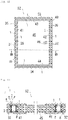
- Fig. 10 is a front view of a sash 50 of a double sliding window according to the present embodiment
- Fig. 11 is a main part cross-sectional view taken along the line A-A of Fig. 10 .
- the sash 50 is to be fixed to a rectangular opening formed in a structure, such as a house, and comprises an outer peripheral rectangular opening frame 10 having an opening, and two sliding screens 20 that are double-sliding screens horizontally movable therein.
- the opening frame 10 as a fitting frame comprises left and right vertical frame members 11 and 12, and upper and lower horizontal frame members 13 and 14.
- the inner space surrounded by the frame members 11 to 14 serves as an opening.
- the two sliding screens 20 as fitting frames close the above opening, and structurally have approximately the same structure.
- Each sliding screen is formed in a rectangular shape by left and right vertical stile members 21 and 22, and upper and lower horizontal stile members 23 and 24, and has a meeting point where the vertical stile members on the center side overlap each other forward and backward.
- the opening frame 10 is composed of a combination of the vertical and horizontal frame members 11 to 14, and the sliding screens 20 and 20 are each composed of a combination of the vertical and horizontal stile members 21 to 24.
- the two sliding screens 20 are slidably supported by the opening frame 10, as described above.
- the vertical and horizontal stile members 21 to 24 that constitute the outer peripheral frame of each sliding screen 20 support a windowpane 25, which is made of wired glass and is positioned in the inside of the sliding screen.
- the windowpane 25 constitutes a fireproof plate material to configure a parting plane between the interior and exterior sides of the sash 50.
- the fireproof plate material is not limited to a windowpane having translucency, but may be a metal plate material, a calcium silicate board, or the like that has a light-blocking effect.
- the structure of the sash 50 is not particularly limited, and may be in any well-known form, as long as the vertical and horizontal frame members 11 to 14 and stile members 21 to 24, which constitute the sash, have hollows extending along the longitudinal direction, and the cross-section orthogonal to the longitudinal direction has one or more hollow spaces.
- the material used for each frame member and stile member constituting the sash may be any material, such as metal, resin, wood, or a composite material thereof; however, metal is preferable.
- the vertical frame members 11 and 12, which constitute the opening frame 10 have hollows 11a and 12a extending and penetrating through the vertical frame members 11 and 12, respectively, in the longitudinal direction.
- the horizontal frame members 13 and 14, which constitute the opening frame 10 also have hollows extending and penetrating through the horizontal frame members 13 and 14 in the longitudinal direction.
- the left and right vertical stile members 21 and 22, which constitute the sliding screen 20 have hollows 21a and 22a extending and penetrating through the vertical stile members 21 and 22, respectively, in the longitudinal direction.
- the horizontal stile members 23 and 24, which constitute the sliding screen 20 also have hollows extending and penetrating through the horizontal stile members 23 and 24 in the longitudinal direction.
- the windowpane 25 made of wired glass is inserted in the internal space formed by the vertical and horizontal stile members. The windowpane 25 is positioned in a stepped part of the vertical stile members 21 and 22, and is fixed by a rubber seal material or a sealing agent 26.
- the thermally expandable fire-resistant materials 1 are inserted into the hollows of the frame members 11 to 14 and the stile members 21 to 24, which respectively constitute the opening frame 10 and the sliding screen 20 of the sash 50.
- grooves 8 are provided between two raised portions 7a or two raised portions 7b, or between one raised portion 7c and each of the frame members 11 to 14 and each of the stile members 21 to 24.
- the projections 5 of the thermally expandable fire-resistant material 1 are fitted to the grooves 8.
- thermally expandable fire-resistant materials 1 are also inserted into the hollows 21a and 22a of the vertical stile members 21 and 22 of each sliding screen 20.
- the thermally expandable fire-resistant materials 1 each have flat portions other than the projections 5, and are inserted into the hollows in a state in which the thermally expandable fire-resistant material 1 is in mutual contact with the wall surface of each hollow parallel to the glass surface.
- the thermally expandable fire-resistant materials 1 are also inserted into the hollows extending and penetrating through the upper and lower horizontal stile members 23 and 24 of each sliding screen 20 in the longitudinal direction.
- the thermally expandable fire-resistant materials 1 inserted into the hollows of the frame members 11 to 14 and the stile members 21 to 24 of the sash 50 are heated by the heat of the fire.
- the thermally expandable fire-resistant materials 1 expand quickly and immediately exhibit fireproof performance.
- Figs. 12 and 13 show a second embodiment in which the present invention is embodied into a fireproof door.
- Fig. 12 is a schematic view showing an example of a fireproof door 52
- Fig. 13 is a main part transverse cross-sectional view taken along the line B-B of Fig. 12 .
- the explanations of portions other than parts necessary for the explanation of the present invention are omitted.
- the fireproof door 52 comprises a rectangular frame 30 as an opening frame having an opening, and a door part 40 rotating around a hinge 35 in the inside of the frame 30.
- the door part 40 has frame members 41 to 44 as an outer peripheral frame, which is a fitting frame, a door body 45 whose outer periphery is supported by the frame members 41 to 44, and a handle 46.
- the material used for each of the frame members 41 to 44 may any material, such as metal, resin, wood, or a composite material thereof; however, metal is preferable.
- the door body 45 is generally made of glass, wood, metal, resin, or the like, and constitutes a fireproof plate material.
- the frame 30 as a fitting frame comprises left and right vertical frame members 31 and 32, and upper and lower horizontal frame members 33 and 34.
- the internal space surrounded by the frame members 31 to 34 serves as an opening.
- the material used for each of the frame members 31 to 34 may be any material, such as metal, resin, wood, or a composite material thereof; however, metal is preferable.
- the thermally expandable fire-resistant materials 1 are placed in the frame members 31, 32, 33, and 34 of the frame 30 along the longitudinal directions of the frame members 31, 32, 33, and 34.
- the thermally expandable fire-resistant materials 1 are also placed in the frame members 41, 42, 43, and 44 of the door part 40 along the longitudinal directions of the frame members 41, 42, 43, and 44.
- the arrangement of the thermally expandable fire-resistant materials 1 in the frame members 31 to 34 and 41 to 44, which form a door sash, is as explained above in the embodiment of the window sash.
- the thermally expandable fire-resistant materials 1 inserted into the frame members 31, 32, 33, and 34 of the frame 30 of the fireproof door 52, and the frame members 41 to 44 of the door part 40 are heated by the heat of the fire.
- the thermally expandable fire-resistant materials 1 expand quickly and immediately exhibit fireproof performance.
- thermally expandable fire-resistant materials 1 are provided in both the frame 30 and the door part 40; however, the thermally expandable fire-resistant materials 1 may be provided in either one of them.
- the present invention can also employ the following structures.
- a fitting frame comprising a frame provided with one or more grooves, and a thermally expandable fire-resistant material fitted to the one or more grooves of the frame, the thermally expandable fire-resistant material comprising a thermally expandable layer containing thermally expandable graphite, and a non-expandable layer provided on one surface of the thermally expandable layer, one or more projections being provided on a surface of the non-expandable layer opposite to or approximately perpendicular to the surface on which the thermally expandable layer is provided, and the one or more projections being fitted to the one or more grooves of the frame.
- a fitting frame comprising a frame provided with one or more grooves, and a thermally expandable fire-resistant material fitted to the one or more grooves of the frame, the thermally expandable fire-resistant material comprising a thermally expandable layer containing thermally expandable graphite, the thermally expandable fire-resistant material being provided with one or more projections, and the one or more projections being fitted to the one or more grooves of the frame so that the thermally expandable layer and the frame are apart from each other.
- a fitting frame comprising a frame provided with one or more grooves, and a thermally expandable fire-resistant material fitted to the one or more grooves, the thermally expandable fire-resistant material comprising a thermally expandable layer containing thermally expandable graphite, one or more projections being provided on a side surface of the thermally expandable layer in a width direction, and the one or more projections being fitted to the one or more grooves of the frame.
- a fitting frame comprising a frame provided with one or more grooves, and a thermally expandable fire-resistant material fitted to the one or more grooves, the thermally expandable fire-resistant material comprising a thermally expandable layer containing thermally expandable graphite, and a non-expandable layer, the non-expandable layer being provided with one or more projections projecting toward the thermally expandable layer, and the one or more projections being fitted to the one or more grooves of the frame so that the thermally expandable layer and the frame are apart from each other.
- a fitting comprising an opening frame having an opening, a plate material that closes the opening of the opening frame, and an outer peripheral frame that supports the outer periphery of the plate material, at least one of the opening frame and the outer peripheral frame comprising the fitting frame according to any one of Items 1 to 6.
- a thermally expandable fire-resistant material comprising a thermally expandable layer containing thermally expandable graphite, and a non-expandable layer provided on one surface of the thermally expandable layer, one or more projections being provided on a surface of the non-expandable layer opposite to or approximately perpendicular to the surface on which the thermally expandable layer is provided.
- a thermally expandable fire-resistant material for being fitted to a frame provided with one or more grooves comprising a thermally expandable layer containing thermally expandable graphite, the thermally expandable fire-resistant material being provided with one or more projections, and the one or more projections having a length that makes the thermally expandable layer and the frame apart from each other when the thermally expandable fire-resistant material is fitted to the one or more grooves of the frame.
- a thermally expandable fire-resistant material comprising a thermally expandable layer containing thermally expandable graphite, and a non-expandable layer provided on one surface of the thermally expandable layer, the non-expandable layer being provided with one or more projections projecting toward the thermally expandable layer.
- a thermally expandable fire-resistant material comprising a thermally expandable layer containing thermally expandable graphite, the thermally expandable layer having a base portion projecting from the thermally expandable layer, and a tip portion closer to a tip than the base portion, and the maximum width of the tip portion being larger than the maximum width of the base portion.
Landscapes
- Engineering & Computer Science (AREA)
- Civil Engineering (AREA)
- Structural Engineering (AREA)
- Health & Medical Sciences (AREA)
- Public Health (AREA)
- Business, Economics & Management (AREA)
- Emergency Management (AREA)
- Special Wing (AREA)
Abstract
Description
- This application claims priority to Japanese Patent Application No.
2015-209115 filed on October 23, 2015 - The present invention relates to a thermally expandable fire-resistant material, a fitting frame, and a fitting that are used for openings of structures, such as houses. More specifically, the present invention relates to a thermally expandable fire-resistant material, a fitting frame, and a fitting that constitute frames of various sash windows or doors etc.
- Fireproof performance is one of the performances required for fittings, such as windows, shoji (paper sliding doors), tobira (i.e., doors), to (Japanese doors), fusuma (Japanese sliding screens), and ramma (transoms), used for the openings of structures, such as houses. In order to enhance fireproof performance, thermally expandable fire-resistant materials are mounted in fittings. In the frames of fittings placed in openings of structures, thermally expandable materials were conventionally mounted in the frames so as to prevent the penetration of flames. For example,
PTL 1 discloses a fireproof resin sash in which thermally expandable fire-resistant materials are inserted into a plurality of hollows in an opening frame of the fireproof resin sash. - PTL 1:
JP4691324B - In conventional sash structures, such as the one disclosed in
PTL 1, thermally expandable fire-resistant materials were placed in direct and close contact with the frames of sashes, doors, etc. Therefore, in the case of fittings made of metal, particularly aluminum, there was a possibility for the fittings to be corroded by the acid components of thermally expandable graphite in the thermally expandable materials. - An object of the present invention is to provide a thermally expandable fire-resistant material, a fitting frame, and a fitting, in which the corrosion of the fitting by the acid components of thermal expansion graphite is prevented.
- To achieve the above object, the present inventors found that a structure in which the thermally expandable layer containing thermally expandable graphite in the thermally expandable fire-resistant material had a minimum area in contact with the frame was advantageous to solve the above problem. Then, the present inventors placed a substantial part of the thermally expandable layer apart from the frame of the fitting. Thus, the present invention has been completed.
- One embodiment of the present invention provides a fitting frame comprising a frame provided with one or more grooves, and a thermally expandable fire-resistant material fitted to the one or more grooves of the frame,
the thermally expandable fire-resistant material comprising a thermally expandable layer containing thermally expandable graphite, and a non-expandable layer provided on one surface of the thermally expandable layer,
one or more projections being provided on a surface of the non-expandable layer opposite to or approximately perpendicular to the surface on which the thermally expandable layer is provided, and
the one or more projections being fitted to the one or more grooves of the frame. - Another embodiment of the present invention provides a fitting frame comprising a frame provided with one or more grooves, and a thermally expandable fire-resistant material fitted to the one or more grooves of the frame,
the thermally expandable fire-resistant material comprising a thermally expandable layer containing thermally expandable graphite,
the thermally expandable fire-resistant material being provided with one or more projections, and
the one or more projections being fitted to the one or more grooves of the frame so that the thermally expandable layer and the frame are apart from each other. - Another embodiment of the present invention provides a fitting frame comprising a frame provided with one or more grooves, and a thermally expandable fire-resistant material fitted to the one or more grooves,
the thermally expandable fire-resistant material comprising a thermally expandable layer containing thermally expandable graphite,
one or more projections being provided on a side surface of the thermally expandable layer in a width direction, and
the one or more projections being fitted to the one or more grooves of the frame. - Another embodiment of the present invention provides a fitting frame comprising a frame provided with one or more grooves, and a thermally expandable fire-resistant material fitted to the one or more grooves,
the thermally expandable fire-resistant material comprising a thermally expandable layer containing thermally expandable graphite, and a non-expandable layer,
the non-expandable layer being provided with one or more projections projecting toward the thermally expandable layer, and
the one or more projections being fitted to the one or more grooves of the frame so that the thermally expandable layer and the frame are apart from each other. - Another embodiment of the present invention provides a fitting comprising an opening frame having an opening, a plate material that closes the opening of the opening frame, and an outer peripheral frame that supports the outer periphery of the plate material,
at least one of the opening frame and the outer peripheral frame comprising the fitting frame according to any one of the above items. - Another embodiment of the present invention provides a thermally expandable fire-resistant material comprising a thermally expandable layer containing thermally expandable graphite, and a non-expandable layer provided on one surface of the thermally expandable layer,
one or more projections being provided on a surface of the non-expandable layer opposite to or approximately perpendicular to a surface on which the thermally expandable layer is provided. - Another embodiment of the present invention provides a thermally expandable fire-resistant material for being fitted to a frame provided with one or more grooves,
the thermally expandable fire-resistant material comprising a thermally expandable layer containing thermally expandable graphite,
the thermally expandable fire-resistant material being provided with one or more projections, and
the one or more projections having a length that makes the thermally expandable layer and the frame apart from each other when the thermally expandable fire-resistant material is fitted to the one or more grooves of the frame. - Another embodiment of the present invention provides a thermally expandable fire-resistant material comprising a thermally expandable layer containing thermally expandable graphite, and a non-expandable layer provided on one surface of the thermally expandable layer,
the non-expandable layer being provided with one or more projections projecting toward the thermally expandable layer. - The present invention can impart excellent fireproof performance to fittings, and can prevent the corrosion of fittings by thermally expandable graphite.
-
-
Fig. 1 is an approximate perspective view of a thermally expandable fire-resistant material according to a first embodiment of the present invention. -
Fig. 2 is a partial cross-sectional view showing a state in which the thermally expandable fire-resistant material ofFig. 1 is mounted in a frame of a sash. -
Fig. 3 is a cross-sectional view showing another example of the thermally expandable fire-resistant material. -
Fig. 4 is an approximate perspective view of a thermally expandable fire-resistant material according to a second embodiment of the present invention. -
Fig. 5 is a cross-sectional view showing another example of the thermally expandable fire-resistant material. -
Fig. 6 is a cross-sectional view showing another example of the thermally expandable fire-resistant material. -
Fig. 7 is a cross-sectional view showing another example of the thermally expandable fire-resistant material. -
Fig. 8 is an approximate perspective view of a thermally expandable fire-resistant material according to a third embodiment of the present invention. -
Fig. 9 is an approximate perspective view of a thermally expandable fire-resistant material according to a fourth embodiment of the present invention. -
Fig. 10 is a front view of a window. -
Fig. 11 is a main part cross-sectional view taken along the line A-A ofFig. 10 . -
Fig. 12 is a front view of a door. -
Fig. 13 is a transverse cross-sectional view taken along the line B-B ofFig. 12 . - In the present specification, the term "building" includes, but is not limited to, building materials for single-family houses, apartments, high-rise residential buildings, high-rise buildings, commercial facilities, public facilities, and the like; and structures such as vessels, including passenger ships, transport vessels, ferries, and the like.
- In the present invention, the term "fitting" includes, but is not limited to, windows (including double sliding windows, casement windows, double hung windows, etc.), shoji (paper sliding doors), tobira (i.e., doors), to (Japanese doors), fusuma (Japanese sliding screens), and ramma (transoms).
- A thermally expandable fire-resistant material according to the first embodiment of the present invention is described with reference to
Figs. 1 and 2 . - As shown in
Fig. 1 , a thermally expandable fire-resistant material 1 to be placed in a fitting frame comprises a thermallyexpandable layer 2 containing thermally expandable graphite, and anon-expandable layer 3. Acoating layer 4 is laminated on the surface of the thermallyexpandable layer 2 on the side opposite to thenon-expandable layer 3. The thermallyexpandable layer 2, thenon-expandable layer 3, and thecoating layer 4 are integrally molded in a sheet form. Further,projections 5 are provided on the surface of thenon-expandable layer 3 opposite to the surface on which the thermallyexpandable layer 2 is provided. Eachprojection 5 has abase portion 5a projecting from thenon-expandable layer 3, and atip portion 5b closer to the tip of the projection than thebase portion 5a. In the present embodiment, the maximum width W2 of thetip portion 5b is larger than the maximum width W1 of thebase portion 5a. The shape of thetip portion 5b is not particularly limited. For example, as shown in the drawing, thetip portion 5b may have an approximately triangular cross-sectional shape tapered toward the tip. Theprojection 5 has a shape matching the groove of the frame of the fitting, as described later. - The thermally
expandable layer 2 is a resin composition containing a resin component, thermally expandable graphite, and an inorganic filler. - The resin component can be selected from a wide range of known resin components. Examples thereof include thermoplastic resins, thermosetting resins, rubber substances, and combinations thereof.
- Examples of thermoplastic resins include polyolefin resins, such as polypropylene resins, polyethylene resins, poly(1-)butene resins, and polypentene resins; and synthetic resins, such as polystyrene resins, acrylonitrile-butadienestyrene (ABS) resins, polycarbonate resins, polyphenylene ether resins, (meth)acrylic resins, polyamide resins, polyvinyl chloride resins, novolak resins, polyurethane resins, and polyisobutylene.
- Examples of thermosetting resins include synthetic resins, such as polyurethane, polyisocyanate, polyisocyanurate, phenol resins, epoxy resins, urea resins, melamine resins, unsaturated polyester resins, and polyimide.
- Examples of rubber substances include natural rubber, isoprene rubber, butadiene rubber, 1,2-polybutadiene rubber, styrene-butadiene rubber, chloroprene rubber, nitrile rubber, butyl rubber, chlorinated butyl rubber, ethylene-propylene rubber, chlorosulfonated polyethylene, acrylic rubber, epichlorohydrin rubber, multi-vulcanized rubber, non-vulcanized rubber, silicone rubber, fluororubber, urethane rubber, and like rubber substances.
- These synthetic resins and/or rubber substances can be used singly or in combination of two or more.
- Preferable among these synthetic resins and/or rubber substances are those that are flexible and have rubber-like properties. Resin components having such properties allow high filling of inorganic fillers, and the resin compositions to be obtained are flexible and easy to handle. In order to obtain resin compositions that are more flexible and easier to handle, non-vulcanized rubber, such as butyl, and polyethylene-based resins are preferably used.
- Alternatively, epoxy resins are preferable in terms of increasing the flame retardancy of the resins themselves and enhancing the fireproof performance.
- The thermally expandable graphite is a conventionally known substance that is produced as a graphite intercalation compound by treating a powder of natural flake graphite, thermal decomposition graphite, kish graphite, or the like, with an inorganic acid such as concentrated sulfuric acid, nitric acid, and selenic acid, and a strong oxidant such as concentrated nitric acid, perchloric acid, perchlorate, permanganate, dichromate, and hydrogen peroxide. The thermally expandable graphite is a crystalline compound in which a carbon layer structure is maintained.
- The thermally expandable graphite obtained by acid treatment may be further neutralized with ammonia, lower aliphatic amine, an alkali metal compound, an alkaline earth metal compound, or the like. Commercial products of thermally expandable graphite include "GREP-EG" produced by Tosoh Corporation, "GRAFGUARD" produced by GrafTech, etc.
- The inorganic filler increases the heat capacity and suppresses the heat transmission when an expandable heat-insulating layer is formed, and acts as an aggregate to increase the strength of the expandable heat-insulating layer. The inorganic filler is not particularly limited, and examples thereof include metal oxides, such as alumina, zinc oxide, titanium oxide, calcium oxide, magnesium oxide, iron oxide, tin oxide, antimony oxide, and ferrite; hydrous inorganic compounds, such as calcium hydroxide, magnesium hydroxide, aluminium hydroxide, and hydrotalcite; metal carbonates, such as basic magnesium carbonate, calcium carbonate, magnesium carbonate, zinc carbonate, strontium carbonate, and barium carbonate; and the like.
- In addition to the above examples, other examples of the inorganic filler include calcium salts, such as calcium sulfate, gypsum fibers, and calcium silicate; silica, diatomite, dawsonite, barium sulfate, talc, clay, mica, montmorillonite, bentonite, activated clay, sepiolite, imogolite, sericite, glass fibers, glass beads, silica balloons, aluminium nitride, boron nitride, silicon nitride, carbon black, graphite, carbon fibers, carbon balloons, charcoal powder, various metal powders, potassium titanate, magnesium sulfate, lead zirconate titanate, zinc stearate, calcium stearate, aluminum borate, molybdenum sulfide, silicon carbide, stainless steel fibers, zinc borate, various magnetic powders, slag fibers, fly ash, dewatered sludge, and the like. These inorganic fillers can be used singly or in combination of two or more.
- The resin composition preferably contains 10 to 350 parts by weight of the thermally expandable graphite and 30 to 400 parts by weight of the inorganic filler, based on 100 parts by weight of the resin component, such as a thermoplastic resin or an epoxy resin.
- Moreover, the total amount of the thermally expandable graphite and the inorganic filler is preferably in the range of 50 to 600 parts by weight based on 100 parts by weight of the resin component.
- This resin composition is expanded by heating and forms a fire-resistant heat-insulating layer. According to this formulation, the thermally expandable fire-resistant material can be expanded by the heating of fire etc. to obtain a necessary coefficient of cubical expansion. The expanded fire-resistant material can form a residue having predetermined heat-insulating capacity and predetermined strength, and can achieve stable fireproof performance.
- In order to increase the strength of the expandable heat-insulating layer and to enhance the fireproof performance, the resin composition that constitutes the thermally expandable fire-resistant material may optionally contain, in addition to the above components, the following components within a range that does not impair the object of the present invention: red phosphorus; various phosphates, such as triphenyl phosphate, tricresyl phosphate, trixylenyl phosphate, cresyl diphenyl phosphate, and xylenyl diphenyl phosphate; metal salts of phosphoric acids, such as sodium phosphate, potassium phosphate, and magnesium phosphate; ammonium polyphosphates; phosphorus compounds, such as compounds represented by formula (1) below; and the like.
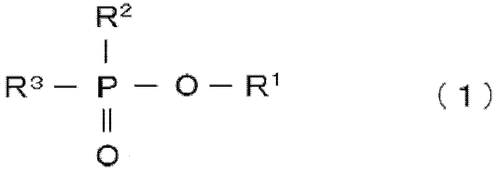
- In formula (1), R1 and R3 are the same or different, and each represent hydrogen, a linear or branched alkyl group having 1 to 16 carbon atoms, or an aryl group having 6 to 16 carbon atoms. R2 represents a hydroxyl group, a linear or branched alkyl group having 1 to 16 carbon atoms, a linear or branched alkoxyl group having 1 to 16 carbon atoms, an aryl group having 6 to 16 carbon atoms, or an aryloxy group having 6 to 16 carbon atoms.
- Furthermore, the resin composition that constitutes the thermally expandable fire-resistant material may optionally contain, within a range that does not impair the object of the present invention, an antioxidant, based on phenol, amine, sulfur, or the like, a metal deterioration inhibitor, an antistatic agent, a stabilizer, a crosslinking agent, a lubricant, a softening agent, a pigment, a tackifier resin, a molding auxiliary material, and like additives; a polybutene, a petroleum resin, and a like tackifier.
- The thermally expandable fire-resistant material is also commercially available. Examples include Fire Barrier produced by Sumitomo 3M (a thermally expandable fire-resistant material comprising a resin composition containing chloroprene rubber and vermiculite; expansion rate: 3 times, heat conductivity: 0.20 kcal/m·h·°C). Mejihikatto produced by Mitsui Kinzoku Paints & Chemicals Co., Ltd. (a thermally expandable fire-resistant material comprising a resin composition containing a polyurethane resin and thermally expandable graphite; expansion rate: 4 times, heat conductivity: 0.21 kcal/m·h·°C), Fi-Block produced by Sekisui Chemical Co., Ltd., and like thermally expandable fire-resistant materials.
- The material constituting the
non-expandable layer 3 may be, for example, metal, a non-expandable resin, or a composite material thereof. The non-expandable resin is made of a thermoplastic resin, a thermosetting resin, an elastomer, rubber, or a combination thereof. Examples of thermoplastic resins include fluororesin, polyphenylene ether, modified polyphenylene ether, polyphenylene sulfide, polycarbonate, polyetherimide, polyetheretherketone, polyarylate, polyamide, polyamideimide, polybutadiene, polyimide, acrylic resin, polyacetal, polyamide, polyethylene, polyethylene terephthalate, polycarbonate, polyester, polystyrene, polyphenylene sulfide, polybutylene terephthalate, polypropylene, polyvinyl chloride, ABS resin, AS resin, and the like. Examples of thermosetting resins include epoxy resins, phenol resins, melamine resins, urea resins, unsaturated polyester resins, alkyd resins, polyurethane, thermosetting polyimide, and the like. Examples of elastomers include olefin-based elastomers, styrene-based elastomers, ester-based elastomers, amide-based elastomers, vinyl chloride-based elastomers, and the like. Examples of rubber include natural rubber, silicone rubber, styrene-butadiene rubber, isoprene rubber, butadiene rubber, chloroprene rubber, acrylonitrile-butadiene rubber, nitrile butadiene rubber, butyl rubber, ethylene-propylene rubber, ethylene-propylene-diene rubber, urethane rubber, silicone rubber, fluororubber, and the like. The non-thermally expandable fire-resistant material may further contain an antioxidant, based on phenol, amine, sulfur, or the like, a metal deterioration inhibitor, an antistatic agent, a stabilizer, a crosslinking agent, a lubricant, a softening agent, a pigment, and the like, within a range that does not impair its physical properties. Further, a general flame retardant may be added. The fireproof performance can be enhanced by the combustion prevention effect of the flame retardant. - The
coating layer 4 may be made of any material that allows expansion of the thermallyexpandable layer 2 upon heating. Combustible materials and noncombustible materials can be used. When thecoating layer 4 is made of a combustible material, the thermallyexpandable layer 2 can be more easily expanded, and predetermined fireproof performance can be well exhibited. - Although the combustible material is not particularly limited, it is preferable to use a thermoplastic resin, an elastomer, rubber, or a combination thereof. Examples of thermoplastic resins include fluororesin, polyphenylene ether, modified polyphenylene ether, polyphenylene sulfide, polycarbonate, polyetherimide, polyetheretherketone, polyarylate, polyamide, polyamideimide, polybutadiene, polyimide, acrylic resin, polyacetal, polyamide, polyethylene, polyethylene terephthalate, polycarbonate, polyester, polystyrene, polyphenylene sulfide, polybutylene terephthalate, polypropylene, polyvinyl chloride, ABS resin, AS resin, and the like. Examples of elastomers include olefin-based elastomers, styrene-based elastomers, ester-based elastomers, amide-based elastomers, vinyl chloride-based elastomers, and the like. Examples of rubber include natural rubber, silicone rubber, styrene-butadiene rubber, isoprene rubber, butadiene rubber, chloroprene rubber, acrylonitrile-butadiene rubber, nitrile butadiene rubber, butyl rubber, ethylene-propylene rubber, ethylene-propylene-diene rubber, urethane rubber, silicone rubber, fluororubber, and the like. The thickness of the
coating layer 4 made of a thermoplastic resin, an elastomer, rubber, or a combination thereof is not particularly limited, but is generally 0.5 to 6 mm. - Moreover, the
coating layer 4 may be made of metal, a metal alloy, or a combination of metal and a combustible material mentioned above. - The
coating layer 4 may have any appearance, and the color and pattern can be determined depending on the purpose. In one embodiment, the color of thecoating layer 4 is similar to the color of aframe 7 of the fitting to which the thermally expandable fire-resistant material 1 is attached. For example, when the thermally expandable fire-resistant material 1 is attached to an aluminum window frame, the color of thecoating layer 4 can be aluminum color. The term "similar color" means that, among three elements represented by the characteristics of color, i.e., hue, brightness, and saturation, the hue is the same or similar. Specifically, warm colors, cold colors, white and opaque white, transparent and semi-transparent colors, etc., can be specified as similar colors. Moreover, designability can be imparted to thecoating layer 4 by forming any pattern, such as a wood grain pattern to give visual warmth. Thus, the designability of black ash color can be increased by coating the thermallyexpandable layer 2 with thecoating layer 4. Furthermore, coating with thecoating layer 4 enhances the weather resistance of the thermallyexpandable layer 2, and also increases the long-term durability of the thermally expandable fire-resistant material 1. - The method for producing the thermally expandable fire-
resistant material 1 is not particularly limited. The thermallyexpandable layer 2, thenon-expandable layer 3, and thecoating layer 4 may be subjected to simultaneous extrusion molding, may be integrally bonded to each other by an adhesion means, such as an adhesive sheet, an adhesive, or the like, or may be integrally bonded together by physical fixation. - A molded product of the resin composition that constitutes the thermally expandable fire-resistant material can be obtained by producing a kneaded product of the resin composition, followed by molding, thereby forming a molded product suitable for the shape and size of the hollow; or by producing a sheet-like or roll-like molded product, followed by cutting.
- The kneaded product of the resin composition can be obtained by mixing and kneading the above components using a known kneading apparatus, such as a Banbury mixer, a kneader mixer, or a kneading roll (and further a Raikai mixer, a planetary stirrer, etc., in the case of a thermosetting resin, such as an epoxy resin). Moreover, in the case of a two-component thermosetting resin, particularly an epoxy resin, the kneaded product may be produced by separately producing kneaded products of each of the two components and a filler by a kneading method mentioned above, supplying each kneaded product by a plunger pump, a snake pump, a gear pump, or the like, and mixing them by a static mixer, a dynamic mixer, etc.
- As the method for molding the resin composition, the above kneaded product can be molded by a known method, such as press molding, calender molding, extrusion molding, or injection molding. Moreover, as the method for molding a two-component thermosetting resin, particularly an epoxy resin, a known method can be suitably used depending on shape, such as roll molding of a sheet molding compound (SMC) etc., coater molding by a roll coater or a blade coater, etc.
- The thickness of the molded product of the resin composition is not limited, but is preferably 0.1 to 6 mm. When the thickness of the molded product is 0.1 mm or more, sufficient fireproof performance can be exhibited due to the thickness of the expandable heat-insulating layer formed by heating. Moreover, when the thickness of the molded product is 6 mm or less, insertion into the hollow can be easy.
-
Fig. 2 shows a state in which the thermally expandable fire-resistant material 1 ofFig. 1 is mounted in theframe 7 of a window sash or door sash as a fitting. In this embodiment, the thermally expandable fire-resistant material 1 is placed in a space extending along the longitudinal direction in the inside of theframe 7. Theframe 7 may be made of any material, such as metal, resin, wood, or a composite material thereof, but is preferably made of metal. The upper end of theframe 7 is provided with a pair of opposite rail-like raisedportions frame 7. Agroove 8a is formed between the two raisedportions 7a, and agroove 8b is formed between the two raisedportions 7b. The twoprojections 5 of the thermally expandable fire-resistant material 1 are fitted to therespective grooves resistant material 1 may be pressed into theframe 7 by applying pressure from above so that theprojections 5 are fitted to thegrooves projections 5 may be fitted to the grooves by inserting theprojections 5 from the end of theframe 7 along the longitudinal direction of the grooves. Aspace 8c is formed among the thermally expandable fire-resistant material 1, the raisedportion 7a, and the raisedportion 7b. The contact between the thermally expandable fire-resistant material 1 and theframe 7 is prevented in a portion of the thermally expandable fire-resistant material 1 in contact with thespace 8c. - According to the structure of the first embodiment, the thermally expandable fire-
resistant material 1 is in contact with theframe 7 by the non-expandable layer 3 (specifically, a portion of the body of thenon-expandable layer 3, and the projections 5), and the thermallyexpandable layer 2 is apart from theframe 7 through thenon-expandable layer 3 and is not in direct contact with theframe 7. Accordingly, acids in the thermallyexpandable layer 2 can be prevented from being transferred to theframe 7 to corrode the metal of theframe 7. - The thermally expandable fire-
resistant material 1 of the first embodiment is not limited to the structure explained above, and can be modified in the following manner. - As shown in
Fig. 3 , the thermally expandable fire-resistant material 1 may comprise the thermallyexpandable layer 2 containing thermally expandable graphite, and thenon-expandable layer 3, and thecoating layer 4 may be omitted. - The shape of the
projection 5 is not limited, and may be an approximately circular cross-sectional shape, an approximately oval shape, an approximately rectangular shape, or the like. Moreover, the maximum width W2 of thetip portion 5b may be equal to or less than the maximum width W1 of thebase portion 5a. - The number of
projections 5 is not limited, and may be singular or plural, such as 3, 4, or 5. Moreover, when a plurality ofprojections 5 is provided, theprojections 5 may have the same shape or different shapes. - The
grooves frame 7 may be provided, not only between the two raisedportions 7a and between the two raisedportions 7b, but also between one raisedportion frame 7 that is not a raised portion. - Next, the thermally expandable fire-resistant material according to the second embodiment of the present invention is described with reference to
Fig. 4 . In order to simplify the explanation, the explanations of the same member numbers as those of the first embodiment are omitted. - As shown in
Fig. 4 , the thermally expandable fire-resistant material 1 placed in a fitting frame comprises a thermallyexpandable layer 2 containing thermally expandable graphite, and acoating layer 4. The thermallyexpandable layer 2 and thecoating layer 4 are integrally molded in a sheet form. Moreover,projections 5 are provided on the surface of the thermallyexpandable layer 2 on the side opposite to the surface on which thecoating layer 4 is provided. Eachprojection 5 has abase portion 5a projecting from the thermallyexpandable layer 2, and atip portion 5b closer to the tip of the projection than thebase portion 5a. Theprojections 5 are made of the same material as the thermallyexpandable layer 2. - The materials constituting the
expandable layer 2 and thecoating layer 4, the materials constituting thebase portion 5a and thetip portion 5b, and the sizes thereof are as described in the first embodiment. - The thermally expandable fire-
resistant material 1 of the second embodiment can be produced by simultaneous extrusion molding or the like, as explained regarding the thermally expandable fire-resistant material 1 of the first embodiment. - In the thermally expandable fire-
resistant material 1 of the second embodiment, eachprojection 5 has a length L that is larger than the depth Dep of acorresponding groove 8a in theframe 7 to be fitted with theprojection 5. Therefore, the body portion of the thermally expandable fire-resistant material 1 extending in the longitudinal direction of the thermally expandable fire-resistant material 1, other than theprojections 5, is apart from theframe 7. The thermallyexpandable layer 2 in any part other than the tip of eachprojection 5 is not in direct contact with theframe 7. Accordingly, acids in the thermallyexpandable layer 2 can be prevented from being transferred to theframe 7 to corrode the metal of theframe 7. - The thermally expandable fire-
resistant material 1 of the second embodiment is not limited to the structure explained above, and can be modified in the following manner. - As shown in
Fig. 5 , the thermally expandable fire-resistant material 1 may comprise the thermallyexpandable layer 2 containing thermally expandable graphite, and thecoating layer 4 may be omitted. - As shown in
Fig. 6 , the thermally expandable fire-resistant material 1 of the second embodiment may also have a structure in which thenon-expandable layer 3, the thermallyexpandable layer 2, and thecoating layer 4 are laminated in this order, as shown inFig. 1 regarding the thermally expandable fire-resistant material 1 of the first embodiment. In this case, theprojections 5 are made of the same material as thenon-expandable layer 3, thenon-expandable layer 3 in any part other than the tip of eachprojection 5 is not in direct contact with theframe 7, and acids in the thermallyexpandable layer 2 can be prevented from being transferred to theframe 7 to corrode the metal of theframe 7. - As shown in
Fig. 7 , thecoating layer 4 may be omitted from the embodiment ofFig. 6 . - The shape of the
projection 5 is not limited, and may be an approximately circular cross-sectional shape, an approximately oval shape, an approximately rectangular shape, or the like. Moreover, the maximum width W2 of thetip portion 5b may be equal to or less than the maximum width W1 of thebase portion 5a. - The number of
projections 5 is not limited, and may be singular or plural, such as 3, 4, or 5. Moreover, when a plurality ofprojections 5 is provided, theprojections 5 may have the same shape or different shapes. - The
grooves frame 7 may be provided, not only between the two raisedportions 7a and between the two raisedportions 7b, but also between one raisedportion frame 7 that is not a raised portion. - In the second embodiment described above, the length L of the
projection 5 is formed larger than the depth Dep of thecorresponding groove 8a in theframe 7 to be fitted with theprojection 5, whereby the body portion of the thermally expandable fire-resistant material 1 is apart from theframe 7; however, the present invention is not limited to this embodiment, as long as the body portion of the thermally expandable fire-resistant material 1 can be apart from theframe 7. - Next, the thermally expandable fire-resistant material according to the third embodiment of the present invention is described below with reference to
Fig. 8 . In order to simplify the explanation, the explanations of the same member numbers as those of the first and second embodiments are omitted. - As shown in
Fig. 8 , the thermally expandable fire-resistant material 1 placed in a fitting frame comprises a thermallyexpandable layer 2 containing thermally expandable graphite, and anon-expandable layer 3 laminated to each other. Acoating layer 4 is laminated on the surface of the thermallyexpandable layer 2 on the side opposite to thenon-expandable layer 3. The thermallyexpandable layer 2, thenon-expandable layer 3, and thecoating layer 4 are integrally molded in a sheet form.Projections 5 are provided on surfaces (in the drawing, side surfaces of thenon-expandable layer 3 in the width direction) approximately perpendicular to the surface of thenon-expandable layer 3 on which the thermallyexpandable layer 2 is provided (the wide surface extending in the longitudinal direction of the thermally expandable layer 2). Eachprojection 5 has abase portion 5a projecting from thenon-expandable layer 3, and atip portion 5b closer to the tip of the projection than thebase portion 5a. In the present embodiment, the maximum width W2 of thetip portion 5b is larger than the maximum width W1 of thebase portion 5a. The shape of thetip portion 5b is not particularly limited; however, for example, thetip portion 5b may have an approximately triangular cross-sectional shape tapered toward the tip, as shown in the drawing. - The
frame 7 of the fitting has a pair of rail-like raisedportions projections 5a extending from the side surfaces of thenon-expandable layer 3 in the width direction are each fitted togrooves portions frame 7. - The thermally expandable fire-
resistant material 1 may be pressed into theframe 7 by applying pressure from above so that theprojections 5 are fitted to thegrooves projections 5 may be fitted to the grooves by inserting theprojections 5 from the end of theframe 7 along the longitudinal direction of the grooves. Aspace 8c is formed among the thermally expandable fire-resistant material 1, the raisedportion 7a, and the raisedportion 7b. The contact between the thermally expandable fire-resistant material 1 and theframe 7 is prevented in a portion of the thermally expandable fire-resistant material 1 in contact with thespace 8c. - The materials constituting the
expandable layer 2 and thecoating layer 4, the materials constituting thebase portion 5a and thetip portion 5b, and the size thereof are as described in the first embodiment. - The thermally expandable fire-
resistant material 1 of the third embodiment can be produced by simultaneous extrusion molding or the like, as explained regarding the thermally expandable fire-resistant material 1 of the first embodiment. - According to the structure of the third embodiment, the thermally expandable fire-
resistant material 1 is in contact with theframe 7 by the non-expandable layer 3 (specifically, a portion of the body of thenon-expandable layer 3, and the projections 5), and the thermallyexpandable layer 2 is apart from theframe 7 through thenon-expandable layer 3 in a direction approximately perpendicular to a direction (horizontal direction in the drawing) supported by theprojections 5, and is not in direct contact with theframe 7. Accordingly, acids in the thermallyexpandable layer 2 can be prevented from being transferred to theframe 7 to corrode the metal of theframe 7. - The thermally expandable fire-
resistant material 1 of the third embodiment is not limited to the structure explained above, and can be modified in the following manner. - As shown in
Fig. 3 , the thermally expandable fire-resistant material 1 may also comprise the thermallyexpandable layer 2 containing thermally expandable graphite, and thenon-expandable layer 3, and thecoating layer 4 may be omitted. - As shown in
Fig. 4 , the length of eachprojection 5 may also be formed larger than the depth of thecorresponding groove 8a in theframe 7 to be fitted with theprojection 5. In this case, the side surfaces of the thermallyexpandable layer 2 can be prevented from being in contact with theframe 7. - As shown in
Fig. 5 , the thermally expandable fire-resistant material 1 may also comprise the thermallyexpandable layers 2 containing thermally expandable graphite, and thecoating layer 4 may be omitted. - The shape of the
projection 5 is not limited, and may be an approximately circular cross-sectional shape, an approximately oval shape, an approximately rectangular shape, or the like. Moreover, the maximum width W2 of thetip portion 5b may be equal to or less than the maximum width W1 of thebase portion 5a. - The number of
projections 5 is not limited, and may be singular or plural, such as 3, 4, or 5. Moreover, when a plurality ofprojections 5 is provided, theprojections 5 may have the same shape or different shapes. - Next, the thermally expandable fire-resistant material according to the fourth embodiment of the present invention is described with reference to
Fig. 9 . In order to simplify the explanation, the explanations of the same member numbers as those of the first to third embodiments are omitted. - As shown in
Fig. 9 , the thermally expandable fire-resistant material 1 placed in a fitting frame comprises a thermallyexpandable layer 2 containing thermally expandable graphite, and anon-expandable layer 3 laminated to each other. The thermallyexpandable layer 2 and thenon-expandable layer 3 are integrally molded in a sheet form. Moreover, a plurality of projections 5 (three projections in the drawing) extends from the surface of thenon-expandable layer 3 on which the thermallyexpandable layer 2 is provided (the wide surface extending in the longitudinal direction of the thermally expandable layer 2). In the present embodiment, theprojections 5 include twoprojections 5 extending from both ends of thenon-expandable layer 3 in the width direction, and aprojection 5c extending apart from the twoprojections 5. Each of the twoprojections 5 has abase portion 5a projecting from thenon-expandable layer 3, and atip portion 5b closer to the tip of the projection than thebase portion 5a. In the present embodiment, the maximum width (the horizontal length in the drawing) of thetip portion 5b is larger than the maximum width (the horizontal length in the drawing) of thebase portion 5a. - The upper end of the
frame 7 is provided with a pair of opposite rail-like raisedportions frame 7. The raisedportions projections 5 have an approximately L-shaped cross-section in the longitudinal direction of the thermally expandable fire-resistant material 1. The raisedportions projections 5. The groove between the two raisedportions frame 7 is divided intospaces projection 5c. Because the distance from the thermallyexpandable layer 2 to theframe 7 across thespaces portions frame 7, the contact between the thermally expandable fire-resistant material 1 (thermally expandable layer 2) and theframe 7 is prevented in portions of the thermally expandable fire-resistant material 1 (thermally expandable layer 2) in contact with thespaces - According to the structure of the first embodiment, the thermally expandable fire-
resistant material 1 is in contact with theframe 7 by the non-expandable layer 3 (specifically, theprojections 5 of the non-expandable layer 3), and the thermallyexpandable layer 2 is apart from theframe 7 and is not in direct contact with theframe 7. Accordingly, acids in the thermallyexpandable layer 2 can be prevented from being transferred to theframe 7 to corrode the metal of theframe 7. - The thermally expandable fire-
resistant material 1 of the fourth embodiment is not limited to the structure explained above, and can be modified in the following manner. - A
coating layer 4 may be further laminated on the surface of thenon-expandable layer 3 opposite to the thermallyexpandable layer 2. - The shape of the
projection 5 is not limited, and may be an approximately circular cross-sectional shape, an approximately oval shape, an approximately rectangular shape, or the like. - The number of
projections 5 is not limited, and may be singular or plural, such as 3, 4, or 5. Moreover, when a plurality ofprojections 5 is provided, theprojections 5 may have the same shape or different shapes. - The number of
projections 5, which have abase portion 5a and atip portion 5b closer to the tip of the projection than thebase portion 5a, and in which the maximum width of thetip portion 5b is larger than the maximum width of thebase portion 5a, may be not only 2, but also 1 or 3 or more. For example, oneprojection 5 may have such a structure, and another orother projections 5 may have an approximately constant width along the full length. - In
Fig. 9 , theprojections 5 extend approximately perpendicularly from the surface of thenon-expandable layer 3 on which the thermallyexpandable layer 2 is provided, but may extend obliquely from the surface of thenon-expandable layer 3 on which the thermallyexpandable layer 2 is provided. - Two or
more projections 5c may be provided, or noprojection 5c may be provided. - The following describes a frame and a fitting, to both of which the thermally expandable fire-
resistant material 1 of the first embodiment, the thermally expandable fire-resistant material 1 of the second embodiment, the thermally expandable fire-resistant material 1 of the third embodiment, or a thermally expandable fire-resistant material 1 that is another example of these embodiments and is included in the scope of the present invention, is applied. -
Fig. 10 is a front view of asash 50 of a double sliding window according to the present embodiment, andFig. 11 is a main part cross-sectional view taken along the line A-A ofFig. 10 . InFigs. 10 and 11 , thesash 50 is to be fixed to a rectangular opening formed in a structure, such as a house, and comprises an outer peripheralrectangular opening frame 10 having an opening, and two slidingscreens 20 that are double-sliding screens horizontally movable therein. - The
opening frame 10 as a fitting frame comprises left and rightvertical frame members horizontal frame members frame members 11 to 14 serves as an opening. The two slidingscreens 20 as fitting frames close the above opening, and structurally have approximately the same structure. Each sliding screen is formed in a rectangular shape by left and rightvertical stile members horizontal stile members opening frame 10 is composed of a combination of the vertical andhorizontal frame members 11 to 14, and the slidingscreens horizontal stile members 21 to 24. - In the
sash 50, the two slidingscreens 20 are slidably supported by theopening frame 10, as described above. The vertical andhorizontal stile members 21 to 24 that constitute the outer peripheral frame of each slidingscreen 20 support awindowpane 25, which is made of wired glass and is positioned in the inside of the sliding screen. Thewindowpane 25 constitutes a fireproof plate material to configure a parting plane between the interior and exterior sides of thesash 50. The fireproof plate material is not limited to a windowpane having translucency, but may be a metal plate material, a calcium silicate board, or the like that has a light-blocking effect. - The structure of the
sash 50 is not particularly limited, and may be in any well-known form, as long as the vertical andhorizontal frame members 11 to 14 andstile members 21 to 24, which constitute the sash, have hollows extending along the longitudinal direction, and the cross-section orthogonal to the longitudinal direction has one or more hollow spaces. In addition, the material used for each frame member and stile member constituting the sash may be any material, such as metal, resin, wood, or a composite material thereof; however, metal is preferable. - The
vertical frame members opening frame 10, havehollows vertical frame members horizontal frame members opening frame 10, also have hollows extending and penetrating through thehorizontal frame members - The left and right
vertical stile members screen 20, havehollows 21a and 22a extending and penetrating through thevertical stile members horizontal stile members screen 20, also have hollows extending and penetrating through thehorizontal stile members windowpane 25 made of wired glass is inserted in the internal space formed by the vertical and horizontal stile members. Thewindowpane 25 is positioned in a stepped part of thevertical stile members agent 26. - The thermally expandable fire-
resistant materials 1 are inserted into the hollows of theframe members 11 to 14 and thestile members 21 to 24, which respectively constitute theopening frame 10 and the slidingscreen 20 of thesash 50. In theframe members 11 to 14 and thestile members 21 to 24,grooves 8 are provided between two raisedportions 7a or two raisedportions 7b, or between one raisedportion 7c and each of theframe members 11 to 14 and each of thestile members 21 to 24. Theprojections 5 of the thermally expandable fire-resistant material 1 are fitted to thegrooves 8. - Further, the thermally expandable fire-
resistant materials 1 are also inserted into thehollows 21a and 22a of thevertical stile members screen 20. The thermally expandable fire-resistant materials 1 each have flat portions other than theprojections 5, and are inserted into the hollows in a state in which the thermally expandable fire-resistant material 1 is in mutual contact with the wall surface of each hollow parallel to the glass surface. Although it is not shown, the thermally expandable fire-resistant materials 1 are also inserted into the hollows extending and penetrating through the upper and lowerhorizontal stile members screen 20 in the longitudinal direction. - If a fire breaks out on the interior or exterior side of the
sash 50, the thermally expandable fire-resistant materials 1 inserted into the hollows of theframe members 11 to 14 and thestile members 21 to 24 of thesash 50 are heated by the heat of the fire. The thermally expandable fire-resistant materials 1 expand quickly and immediately exhibit fireproof performance. -
Figs. 12 and 13 show a second embodiment in which the present invention is embodied into a fireproof door.Fig. 12 is a schematic view showing an example of afireproof door 52, andFig. 13 is a main part transverse cross-sectional view taken along the line B-B ofFig. 12 . InFig. 12 , the explanations of portions other than parts necessary for the explanation of the present invention are omitted. - In
Fig. 12 , thefireproof door 52 comprises arectangular frame 30 as an opening frame having an opening, and adoor part 40 rotating around ahinge 35 in the inside of theframe 30. Thedoor part 40 hasframe members 41 to 44 as an outer peripheral frame, which is a fitting frame, adoor body 45 whose outer periphery is supported by theframe members 41 to 44, and ahandle 46. The material used for each of theframe members 41 to 44 may any material, such as metal, resin, wood, or a composite material thereof; however, metal is preferable. - The
door body 45 is generally made of glass, wood, metal, resin, or the like, and constitutes a fireproof plate material. - The
frame 30 as a fitting frame comprises left and rightvertical frame members horizontal frame members frame members 31 to 34 serves as an opening. The material used for each of theframe members 31 to 34 may be any material, such as metal, resin, wood, or a composite material thereof; however, metal is preferable. - Referring to
Fig. 12 , the thermally expandable fire-resistant materials 1 are placed in theframe members frame 30 along the longitudinal directions of theframe members resistant materials 1 are also placed in theframe members door part 40 along the longitudinal directions of theframe members resistant materials 1 in theframe members 31 to 34 and 41 to 44, which form a door sash, is as explained above in the embodiment of the window sash. - If a fire breaks out on the interior or exterior side of the
fireproof door 52, the thermally expandable fire-resistant materials 1 inserted into theframe members frame 30 of thefireproof door 52, and theframe members 41 to 44 of thedoor part 40 are heated by the heat of the fire. The thermally expandable fire-resistant materials 1 expand quickly and immediately exhibit fireproof performance. - In this drawing, the thermally expandable fire-
resistant materials 1 are provided in both theframe 30 and thedoor part 40; however, the thermally expandable fire-resistant materials 1 may be provided in either one of them. - In
Fig. 13 , theprojections 5 of the thermally expandable fire-resistant materials 1 are fitted to thegrooves 8 of theframes - The embodiments of the present invention are specifically described above; however, the present invention is not limited to the above embodiments, and various modifications based on the technical idea of the present invention can be applied.
- In addition, the present invention can also employ the following structures.
- [Item 1] A fitting frame comprising a frame provided with one or more grooves, and a thermally expandable fire-resistant material fitted to the one or more grooves of the frame,
the thermally expandable fire-resistant material comprising a thermally expandable layer containing thermally expandable graphite, and a non-expandable layer provided on one surface of the thermally expandable layer,
one or more projections being provided on a surface of the non-expandable layer opposite to or approximately perpendicular to the surface on which the thermally expandable layer is provided, and
the one or more projections being fitted to the one or more grooves of the frame. - [Item 2] A fitting frame comprising a frame provided with one or more grooves, and a thermally expandable fire-resistant material fitted to the one or more grooves of the frame,
the thermally expandable fire-resistant material comprising a thermally expandable layer containing thermally expandable graphite,
the thermally expandable fire-resistant material being provided with one or more projections, and
the one or more projections being fitted to the one or more grooves of the frame so that the thermally expandable layer and the frame are apart from each other. - [Item 3] The fitting frame according to
Item 2, wherein the thermally expandable fire-resistant material comprises a non-expandable layer, and the one or more projections are provided on a surface of the non-expandable layer opposite to a surface on which the thermally expandable layer is provided. - [Item 4] A fitting frame comprising a frame provided with one or more grooves, and a thermally expandable fire-resistant material fitted to the one or more grooves,
the thermally expandable fire-resistant material comprising a thermally expandable layer containing thermally expandable graphite,
one or more projections being provided on a side surface of the thermally expandable layer in a width direction, and
the one or more projections being fitted to the one or more grooves of the frame. - [Item 5] A fitting frame comprising a frame provided with one or more grooves, and a thermally expandable fire-resistant material fitted to the one or more grooves,
the thermally expandable fire-resistant material comprising a thermally expandable layer containing thermally expandable graphite, and a non-expandable layer,
the non-expandable layer being provided with one or more projections projecting toward the thermally expandable layer, and
the one or more projections being fitted to the one or more grooves of the frame so that the thermally expandable layer and the frame are apart from each other. - [Item 6] The fitting frame according to any one of
Items 1 to 5, wherein the thermally expandable fire-resistant material comprises a coating layer. - [Item 7] A fitting comprising an opening frame having an opening, a plate material that closes the opening of the opening frame, and an outer peripheral frame that supports the outer periphery of the plate material,
at least one of the opening frame and the outer peripheral frame comprising the fitting frame according to any one ofItems 1 to 6. - [Item 8] The fitting according to
Item 7, which is a window or a door. - [Item 9] A thermally expandable fire-resistant material comprising a thermally expandable layer containing thermally expandable graphite, and a non-expandable layer provided on one surface of the thermally expandable layer,
one or more projections being provided on a surface of the non-expandable layer opposite to or approximately perpendicular to the surface on which the thermally expandable layer is provided. - [Item 10] A thermally expandable fire-resistant material for being fitted to a frame provided with one or more grooves,
the thermally expandable fire-resistant material comprising a thermally expandable layer containing thermally expandable graphite,
the thermally expandable fire-resistant material being provided with one or more projections, and
the one or more projections having a length that makes the thermally expandable layer and the frame apart from each other when the thermally expandable fire-resistant material is fitted to the one or more grooves of the frame. - [Item 11] A thermally expandable fire-resistant material comprising a thermally expandable layer containing thermally expandable graphite, and a non-expandable layer provided on one surface of the thermally expandable layer,
the non-expandable layer being provided with one or more projections projecting toward the thermally expandable layer. - [Item 12] The thermally expandable fire-resistant material according to any one of Items 9 to 11, wherein the thermally expandable fire-resistant material comprises a coating layer.
- [Item 13] A thermally expandable fire-resistant material comprising a thermally expandable layer containing thermally expandable graphite,
the thermally expandable layer having a base portion projecting from the thermally expandable layer, and a tip portion closer to a tip than the base portion, and
the maximum width of the tip portion being larger than the maximum width of the base portion.
Claims (12)
- A fitting frame comprising a frame provided with one or more grooves, and a thermally expandable fire-resistant material fitted to the one or more grooves of the frame,
the thermally expandable fire-resistant material comprising a thermally expandable layer containing thermally expandable graphite, and a non-expandable layer provided on one surface of the thermally expandable layer,
one or more projections being provided on a surface of the non-expandable layer opposite to or approximately perpendicular to the surface on which the thermally expandable layer is provided, and
the one or more projections being fitted to the one or more grooves of the frame. - A fitting frame comprising a frame provided with one or more grooves, and a thermally expandable fire-resistant material fitted to the one or more grooves of the frame,
the thermally expandable fire-resistant material comprising a thermally expandable layer containing thermally expandable graphite,
the thermally expandable fire-resistant material being provided with one or more projections, and
the one or more projections being fitted to the one or more grooves of the frame so that the thermally expandable layer and the frame are apart from each other. - The fitting frame according to claim 2, wherein the thermally expandable fire-resistant material comprises a non-expandable layer, and the one or more projections are provided on a surface of the non-expandable layer opposite to a surface on which the thermally expandable layer is provided.
- A fitting frame comprising a frame provided with one or more grooves, and a thermally expandable fire-resistant material fitted to the one or more grooves,
the thermally expandable fire-resistant material comprising a thermally expandable layer containing thermally expandable graphite,
one or more projections being provided on a side surface of the thermally expandable layer in a width direction, and
the one or more projections being fitted to the one or more grooves of the frame. - A fitting frame comprising a frame provided with one or more grooves, and a thermally expandable fire-resistant material fitted to the one or more grooves,
the thermally expandable fire-resistant material comprising a thermally expandable layer containing thermally expandable graphite, and a non-expandable layer,
the non-expandable layer being provided with one or more projections projecting toward the thermally expandable layer, and
the one or more projections being fitted to the one or more grooves of the frame so that the thermally expandable layer and the frame are apart from each other. - The fitting frame according to any one of claims 1 to 5, wherein the thermally expandable fire-resistant material comprises a coating layer.
- A fitting comprising an opening frame having an opening, a plate material that closes the opening of the opening frame, and an outer peripheral frame that supports the outer periphery of the plate material,
at least one of the opening frame and the outer peripheral frame comprising the fitting frame according to any one of claims 1 to 6. - The fitting according to claim 7, which is a window or a door.
- A thermally expandable fire-resistant material comprising a thermally expandable layer containing thermally expandable graphite, and a non-expandable layer provided on one surface of the thermally expandable layer,
one or more projections being provided on a surface of the non-expandable layer opposite to or approximately perpendicular to the surface on which the thermally expandable layer is provided. - A thermally expandable fire-resistant material for being fitted to a frame provided with one or more grooves,
the thermally expandable fire-resistant material comprising a thermally expandable layer containing thermally expandable graphite,
the thermally expandable fire-resistant material being provided with one or more projections, and
the one or more projections having a length that makes the thermally expandable layer and the frame apart from each other when the thermally expandable fire-resistant material is fitted to the one or more grooves of the frame. - A thermally expandable fire-resistant material comprising a thermally expandable layer containing thermally expandable graphite, and a non-expandable layer provided on one surface of the thermally expandable layer,
the non-expandable layer being provided with one or more projections projecting toward the thermally expandable layer. - The thermally expandable fire-resistant material according to any one of claims 9 to 11, wherein the thermally expandable fire-resistant material comprises a coating layer.
Applications Claiming Priority (2)
| Application Number | Priority Date | Filing Date | Title |
|---|---|---|---|
| JP2015209115 | 2015-10-23 | ||
| PCT/JP2016/081328 WO2017069264A1 (en) | 2015-10-23 | 2016-10-21 | Fireproof sliding door and window |
Publications (2)
| Publication Number | Publication Date |
|---|---|
| EP3366876A1 true EP3366876A1 (en) | 2018-08-29 |
| EP3366876A4 EP3366876A4 (en) | 2019-07-03 |
Family
ID=58557179
Family Applications (1)
| Application Number | Title | Priority Date | Filing Date |
|---|---|---|---|
| EP16857577.7A Withdrawn EP3366876A4 (en) | 2015-10-23 | 2016-10-21 | IGNIFUGES WINDOW AND SLIDING DOOR |
Country Status (4)
| Country | Link |
|---|---|
| EP (1) | EP3366876A4 (en) |
| JP (1) | JP6259932B2 (en) |
| KR (1) | KR20180073565A (en) |
| WO (1) | WO2017069264A1 (en) |
Families Citing this family (7)
| Publication number | Priority date | Publication date | Assignee | Title |
|---|---|---|---|---|
| JP6867154B2 (en) * | 2015-12-25 | 2021-04-28 | 積水化学工業株式会社 | Thermally expandable refractory material |
| JP6907068B2 (en) * | 2017-08-10 | 2021-07-21 | 三協立山株式会社 | Insulated sash |
| JP7036641B2 (en) * | 2018-03-22 | 2022-03-15 | Ykk Ap株式会社 | Support structure and fittings for heat-expandable members |
| CN113107332B (en) * | 2021-05-10 | 2022-02-01 | 安徽钟南消防科技有限公司 | Energy-conserving fire window of flat-open type |
| KR102345622B1 (en) * | 2021-06-04 | 2021-12-31 | 주식회사 에프알인더스 | Window for fireproof and insulation |
| KR102483054B1 (en) * | 2021-07-19 | 2022-12-30 | (주)알루코 | Aluminum fire-proof windows with structures against flame and smoke blocking |
| GB2625988B (en) * | 2023-01-03 | 2025-01-29 | Intumescent Systems Ltd | Fire retardant strip |
Family Cites Families (14)
| Publication number | Priority date | Publication date | Assignee | Title |
|---|---|---|---|---|
| JP2558751Y2 (en) * | 1991-07-25 | 1998-01-14 | 株式会社ノダ | Fire door |
| GB9505642D0 (en) * | 1995-03-21 | 1995-05-10 | Dixon Int Group Ltd | Laminate for improving fire resistance |
| IT1315564B1 (en) * | 2000-12-12 | 2003-02-18 | Marvon Srl | INTUMESCENT GASKET REINFORCED |
| US20020113377A1 (en) * | 2001-02-01 | 2002-08-22 | Lorient Polyproducts Limited | Gas seal |
| DK1377723T3 (en) * | 2001-04-10 | 2010-07-19 | Vkr Holding As | A fireproof window |
| BE1016078A6 (en) * | 2004-06-17 | 2006-02-07 | Reynaers Aluminium Nv | IMPROVED FIRE-RESISTANT WINDOW OR DOOR PROFILE. |
| JP4547611B2 (en) * | 2004-06-25 | 2010-09-22 | 興亜不燃板工業株式会社 | Fireproof joint structure |
| SG132528A1 (en) * | 2005-11-10 | 2007-06-28 | Lee Hoong Thye Eldon | Ceramic doors and boards and applications thereof |
| DE102007008346A1 (en) * | 2007-02-20 | 2008-08-21 | Eduard Hueck Gmbh & Co. Kg | Hollow section for e.g. fire protection window, has fire protection insert provided for extension of service life of hollow section in case of fire, and exhibiting layers that are made of different fire protection materials |
| JP5347103B1 (en) * | 2011-11-29 | 2013-11-20 | 積水化学工業株式会社 | Thermal expansion multilayer packing for building materials |
| JP6147101B2 (en) * | 2013-01-22 | 2017-06-14 | 積水化学工業株式会社 | Thermally expandable refractory resin composition |
| GB2510614B (en) * | 2013-02-08 | 2017-07-05 | Integrated Doorset Solutions Ltd | A fire seal |
| JP6514428B2 (en) * | 2013-11-21 | 2019-05-15 | 積水化学工業株式会社 | Thermal expansion material given design |
| JP6397324B2 (en) * | 2013-12-20 | 2018-09-26 | 積水化学工業株式会社 | Tight materials for joinery with fire resistance |
-
2016
- 2016-10-21 JP JP2016567695A patent/JP6259932B2/en active Active
- 2016-10-21 KR KR1020187009394A patent/KR20180073565A/en not_active Ceased
- 2016-10-21 EP EP16857577.7A patent/EP3366876A4/en not_active Withdrawn
- 2016-10-21 WO PCT/JP2016/081328 patent/WO2017069264A1/en not_active Ceased
Also Published As
| Publication number | Publication date |
|---|---|
| JPWO2017069264A1 (en) | 2017-10-19 |
| WO2017069264A1 (en) | 2017-04-27 |
| KR20180073565A (en) | 2018-07-02 |
| EP3366876A4 (en) | 2019-07-03 |
| JP6259932B2 (en) | 2018-01-10 |
Similar Documents
| Publication | Publication Date | Title |
|---|---|---|
| JP6259932B2 (en) | Fireproof joinery | |
| ES2643024T3 (en) | Flame retardant resin frame | |
| JP6927948B2 (en) | A refractory molded product and a molded product having a refractory molded product | |
| JP6837736B2 (en) | Through-hole cover and fireproof structure of compartment through-hole | |
| JP7016922B2 (en) | Fireproof fittings | |
| JP6777427B2 (en) | Fire protection material and fire protection structure of compartment penetration | |
| JP2017020205A (en) | Thermally-expansive fire-resistant material, opening frame body and fitting | |
| JP6713757B2 (en) | Manufacturing method of building members | |
| JP6683519B2 (en) | Fireproof structure of the fireproof cover and compartment penetration | |
| EP3594424B1 (en) | Multicolor molded article molding material with excellent rigidity and fire resistance | |
| JP6867157B2 (en) | Sleeve, compartment penetration structure, and fireproof filling structure | |
| JP6539060B2 (en) | Fireproof fixture | |
| JP6832397B2 (en) | Thermally expandable refractory materials, opening frames, and fittings | |
| JPWO2006054572A1 (en) | Penetration through structure of compartment | |
| JP6908524B2 (en) | Sleeve for forming compartment through holes in buildings | |
| JP6941662B2 (en) | Coating material, piping, and fireproof structure | |
| JP6357437B2 (en) | Covering material, piping, and fireproof structure | |
| JP6876396B2 (en) | Fireproof filling structure and construction method of fireproof filling structure | |
| JP6789097B2 (en) | Windbreak member and joinery frame | |
| JP6985456B2 (en) | Manufacturing method of building materials | |
| JP2017066851A (en) | Fire prevention structure of penetrating part in hollow structure | |
| JP6867154B2 (en) | Thermally expandable refractory material | |
| JP2016151118A (en) | Frame fitted with fireproof material, fixture fitted with fireproof material, and method of installing fireproof material to frame or fixture | |
| JP6641417B2 (en) | Coating materials, piping, and fire-resistant structures | |
| JP6546499B2 (en) | Fireproof structure of building compartments |
Legal Events
| Date | Code | Title | Description |
|---|---|---|---|
| STAA | Information on the status of an ep patent application or granted ep patent |
Free format text: STATUS: THE INTERNATIONAL PUBLICATION HAS BEEN MADE |
|
| PUAI | Public reference made under article 153(3) epc to a published international application that has entered the european phase |
Free format text: ORIGINAL CODE: 0009012 |
|
| STAA | Information on the status of an ep patent application or granted ep patent |
Free format text: STATUS: REQUEST FOR EXAMINATION WAS MADE |
|
| 17P | Request for examination filed |
Effective date: 20180516 |
|
| AK | Designated contracting states |
Kind code of ref document: A1 Designated state(s): AL AT BE BG CH CY CZ DE DK EE ES FI FR GB GR HR HU IE IS IT LI LT LU LV MC MK MT NL NO PL PT RO RS SE SI SK SM TR |
|
| AX | Request for extension of the european patent |
Extension state: BA ME |
|
| DAV | Request for validation of the european patent (deleted) | ||
| DAX | Request for extension of the european patent (deleted) | ||
| A4 | Supplementary search report drawn up and despatched |
Effective date: 20190603 |
|
| RIC1 | Information provided on ipc code assigned before grant |
Ipc: E06B 5/16 20060101AFI20190527BHEP Ipc: A62C 2/00 20060101ALI20190527BHEP |
|
| STAA | Information on the status of an ep patent application or granted ep patent |
Free format text: STATUS: EXAMINATION IS IN PROGRESS |
|
| 17Q | First examination report despatched |
Effective date: 20220811 |
|
| STAA | Information on the status of an ep patent application or granted ep patent |
Free format text: STATUS: THE APPLICATION IS DEEMED TO BE WITHDRAWN |
|
| 18D | Application deemed to be withdrawn |
Effective date: 20250218 |