EP3366795A1 - Cutting tool - Google Patents
Cutting tool Download PDFInfo
- Publication number
- EP3366795A1 EP3366795A1 EP17158407.1A EP17158407A EP3366795A1 EP 3366795 A1 EP3366795 A1 EP 3366795A1 EP 17158407 A EP17158407 A EP 17158407A EP 3366795 A1 EP3366795 A1 EP 3366795A1
- Authority
- EP
- European Patent Office
- Prior art keywords
- area
- cutting tool
- grains
- gamma phase
- cemented carbide
- Prior art date
- Legal status (The legal status is an assumption and is not a legal conclusion. Google has not performed a legal analysis and makes no representation as to the accuracy of the status listed.)
- Withdrawn
Links
- 238000005520 cutting process Methods 0.000 title claims abstract description 33
- 239000000758 substrate Substances 0.000 claims abstract description 22
- 230000002159 abnormal effect Effects 0.000 claims abstract description 19
- 239000011230 binding agent Substances 0.000 claims abstract description 18
- 239000002245 particle Substances 0.000 claims description 27
- 238000001887 electron backscatter diffraction Methods 0.000 claims description 25
- 150000001247 metal acetylides Chemical class 0.000 claims description 17
- 230000001186 cumulative effect Effects 0.000 claims description 16
- 238000004458 analytical method Methods 0.000 claims description 12
- 238000009826 distribution Methods 0.000 claims description 9
- 239000011248 coating agent Substances 0.000 claims description 7
- 238000000576 coating method Methods 0.000 claims description 7
- 229910052758 niobium Inorganic materials 0.000 claims description 5
- 229910052719 titanium Inorganic materials 0.000 claims description 5
- 238000012937 correction Methods 0.000 claims description 4
- 229910052720 vanadium Inorganic materials 0.000 claims description 3
- 229910052726 zirconium Inorganic materials 0.000 claims description 3
- 229910052804 chromium Inorganic materials 0.000 claims description 2
- 229910052735 hafnium Inorganic materials 0.000 claims description 2
- 239000006104 solid solution Substances 0.000 claims description 2
- 229910052715 tantalum Inorganic materials 0.000 claims description 2
- 239000004033 plastic Substances 0.000 abstract description 2
- 229920003023 plastic Polymers 0.000 abstract description 2
- 239000000843 powder Substances 0.000 description 36
- 238000003801 milling Methods 0.000 description 34
- 230000000052 comparative effect Effects 0.000 description 19
- 239000002002 slurry Substances 0.000 description 18
- 239000007788 liquid Substances 0.000 description 14
- 239000000463 material Substances 0.000 description 14
- 239000002202 Polyethylene glycol Substances 0.000 description 12
- 229920001223 polyethylene glycol Polymers 0.000 description 12
- 239000000203 mixture Substances 0.000 description 8
- 239000002994 raw material Substances 0.000 description 8
- 230000005389 magnetism Effects 0.000 description 7
- LFQSCWFLJHTTHZ-UHFFFAOYSA-N Ethanol Chemical compound CCO LFQSCWFLJHTTHZ-UHFFFAOYSA-N 0.000 description 6
- 238000005229 chemical vapour deposition Methods 0.000 description 6
- 238000005259 measurement Methods 0.000 description 6
- XLYOFNOQVPJJNP-UHFFFAOYSA-N water Substances O XLYOFNOQVPJJNP-UHFFFAOYSA-N 0.000 description 6
- 229910052742 iron Inorganic materials 0.000 description 5
- XEEYBQQBJWHFJM-UHFFFAOYSA-N iron Substances [Fe] XEEYBQQBJWHFJM-UHFFFAOYSA-N 0.000 description 5
- 238000004519 manufacturing process Methods 0.000 description 5
- 229910052759 nickel Inorganic materials 0.000 description 5
- 238000003825 pressing Methods 0.000 description 5
- 239000007921 spray Substances 0.000 description 5
- 229910000831 Steel Inorganic materials 0.000 description 4
- ATJFFYVFTNAWJD-UHFFFAOYSA-N Tin Chemical compound [Sn] ATJFFYVFTNAWJD-UHFFFAOYSA-N 0.000 description 4
- 229910052782 aluminium Inorganic materials 0.000 description 4
- 239000010959 steel Substances 0.000 description 4
- 229910019580 Cr Zr Inorganic materials 0.000 description 3
- 229910052799 carbon Inorganic materials 0.000 description 3
- 238000012512 characterization method Methods 0.000 description 3
- 238000010438 heat treatment Methods 0.000 description 3
- WFKWXMTUELFFGS-UHFFFAOYSA-N tungsten Chemical compound [W] WFKWXMTUELFFGS-UHFFFAOYSA-N 0.000 description 3
- 229910052721 tungsten Inorganic materials 0.000 description 3
- PNEYBMLMFCGWSK-UHFFFAOYSA-N aluminium oxide Inorganic materials [O-2].[O-2].[O-2].[Al+3].[Al+3] PNEYBMLMFCGWSK-UHFFFAOYSA-N 0.000 description 2
- 238000007796 conventional method Methods 0.000 description 2
- 229910052593 corundum Inorganic materials 0.000 description 2
- 239000002173 cutting fluid Substances 0.000 description 2
- 229910003460 diamond Inorganic materials 0.000 description 2
- 239000010432 diamond Substances 0.000 description 2
- 238000000034 method Methods 0.000 description 2
- 238000005240 physical vapour deposition Methods 0.000 description 2
- 238000005498 polishing Methods 0.000 description 2
- 229910052594 sapphire Inorganic materials 0.000 description 2
- 229910001845 yogo sapphire Inorganic materials 0.000 description 2
- 229910001018 Cast iron Inorganic materials 0.000 description 1
- 230000001133 acceleration Effects 0.000 description 1
- 230000015572 biosynthetic process Effects 0.000 description 1
- 238000005422 blasting Methods 0.000 description 1
- 230000001680 brushing effect Effects 0.000 description 1
- 239000013590 bulk material Substances 0.000 description 1
- 239000000470 constituent Substances 0.000 description 1
- 239000013078 crystal Substances 0.000 description 1
- 230000007547 defect Effects 0.000 description 1
- 238000010586 diagram Methods 0.000 description 1
- 238000010894 electron beam technology Methods 0.000 description 1
- 238000013213 extrapolation Methods 0.000 description 1
- 238000010191 image analysis Methods 0.000 description 1
- 238000003780 insertion Methods 0.000 description 1
- 230000037431 insertion Effects 0.000 description 1
- 238000003754 machining Methods 0.000 description 1
- 239000002184 metal Substances 0.000 description 1
- 229910052751 metal Inorganic materials 0.000 description 1
- 238000001000 micrograph Methods 0.000 description 1
- 230000003287 optical effect Effects 0.000 description 1
- 238000012545 processing Methods 0.000 description 1
- 238000005245 sintering Methods 0.000 description 1
- 239000000243 solution Substances 0.000 description 1
- 229910001220 stainless steel Inorganic materials 0.000 description 1
- 239000010935 stainless steel Substances 0.000 description 1
- 230000003068 static effect Effects 0.000 description 1
- 239000000126 substance Substances 0.000 description 1
- 238000012360 testing method Methods 0.000 description 1
- 238000011282 treatment Methods 0.000 description 1
- 229910052725 zinc Inorganic materials 0.000 description 1
Images

Classifications
-
- C—CHEMISTRY; METALLURGY
- C22—METALLURGY; FERROUS OR NON-FERROUS ALLOYS; TREATMENT OF ALLOYS OR NON-FERROUS METALS
- C22C—ALLOYS
- C22C29/00—Alloys based on carbides, oxides, nitrides, borides, or silicides, e.g. cermets, or other metal compounds, e.g. oxynitrides, sulfides
- C22C29/02—Alloys based on carbides, oxides, nitrides, borides, or silicides, e.g. cermets, or other metal compounds, e.g. oxynitrides, sulfides based on carbides or carbonitrides
- C22C29/06—Alloys based on carbides, oxides, nitrides, borides, or silicides, e.g. cermets, or other metal compounds, e.g. oxynitrides, sulfides based on carbides or carbonitrides based on carbides, but not containing other metal compounds
- C22C29/08—Alloys based on carbides, oxides, nitrides, borides, or silicides, e.g. cermets, or other metal compounds, e.g. oxynitrides, sulfides based on carbides or carbonitrides based on carbides, but not containing other metal compounds based on tungsten carbide
-
- B—PERFORMING OPERATIONS; TRANSPORTING
- B22—CASTING; POWDER METALLURGY
- B22F—WORKING METALLIC POWDER; MANUFACTURE OF ARTICLES FROM METALLIC POWDER; MAKING METALLIC POWDER; APPARATUS OR DEVICES SPECIALLY ADAPTED FOR METALLIC POWDER
- B22F7/00—Manufacture of composite layers, workpieces, or articles, comprising metallic powder, by sintering the powder, with or without compacting wherein at least one part is obtained by sintering or compression
- B22F7/06—Manufacture of composite layers, workpieces, or articles, comprising metallic powder, by sintering the powder, with or without compacting wherein at least one part is obtained by sintering or compression of composite workpieces or articles from parts, e.g. to form tipped tools
-
- B—PERFORMING OPERATIONS; TRANSPORTING
- B23—MACHINE TOOLS; METAL-WORKING NOT OTHERWISE PROVIDED FOR
- B23P—METAL-WORKING NOT OTHERWISE PROVIDED FOR; COMBINED OPERATIONS; UNIVERSAL MACHINE TOOLS
- B23P15/00—Making specific metal objects by operations not covered by a single other subclass or a group in this subclass
- B23P15/28—Making specific metal objects by operations not covered by a single other subclass or a group in this subclass cutting tools
-
- C—CHEMISTRY; METALLURGY
- C22—METALLURGY; FERROUS OR NON-FERROUS ALLOYS; TREATMENT OF ALLOYS OR NON-FERROUS METALS
- C22C—ALLOYS
- C22C29/00—Alloys based on carbides, oxides, nitrides, borides, or silicides, e.g. cermets, or other metal compounds, e.g. oxynitrides, sulfides
- C22C29/005—Alloys based on carbides, oxides, nitrides, borides, or silicides, e.g. cermets, or other metal compounds, e.g. oxynitrides, sulfides comprising a particular metallic binder
-
- B—PERFORMING OPERATIONS; TRANSPORTING
- B22—CASTING; POWDER METALLURGY
- B22F—WORKING METALLIC POWDER; MANUFACTURE OF ARTICLES FROM METALLIC POWDER; MAKING METALLIC POWDER; APPARATUS OR DEVICES SPECIALLY ADAPTED FOR METALLIC POWDER
- B22F5/00—Manufacture of workpieces or articles from metallic powder characterised by the special shape of the product
- B22F2005/001—Cutting tools, earth boring or grinding tool other than table ware
-
- B—PERFORMING OPERATIONS; TRANSPORTING
- B22—CASTING; POWDER METALLURGY
- B22F—WORKING METALLIC POWDER; MANUFACTURE OF ARTICLES FROM METALLIC POWDER; MAKING METALLIC POWDER; APPARATUS OR DEVICES SPECIALLY ADAPTED FOR METALLIC POWDER
- B22F2301/00—Metallic composition of the powder or its coating
- B22F2301/15—Nickel or cobalt
-
- B—PERFORMING OPERATIONS; TRANSPORTING
- B22—CASTING; POWDER METALLURGY
- B22F—WORKING METALLIC POWDER; MANUFACTURE OF ARTICLES FROM METALLIC POWDER; MAKING METALLIC POWDER; APPARATUS OR DEVICES SPECIALLY ADAPTED FOR METALLIC POWDER
- B22F2302/00—Metal Compound, non-Metallic compound or non-metal composition of the powder or its coating
- B22F2302/10—Carbide
-
- B—PERFORMING OPERATIONS; TRANSPORTING
- B23—MACHINE TOOLS; METAL-WORKING NOT OTHERWISE PROVIDED FOR
- B23B—TURNING; BORING
- B23B2224/00—Materials of tools or workpieces composed of a compound including a metal
- B23B2224/24—Titanium aluminium nitride
-
- B—PERFORMING OPERATIONS; TRANSPORTING
- B23—MACHINE TOOLS; METAL-WORKING NOT OTHERWISE PROVIDED FOR
- B23B—TURNING; BORING
- B23B2224/00—Materials of tools or workpieces composed of a compound including a metal
- B23B2224/32—Titanium carbide nitride (TiCN)
-
- B—PERFORMING OPERATIONS; TRANSPORTING
- B23—MACHINE TOOLS; METAL-WORKING NOT OTHERWISE PROVIDED FOR
- B23B—TURNING; BORING
- B23B2224/00—Materials of tools or workpieces composed of a compound including a metal
- B23B2224/36—Titanium nitride
-
- B—PERFORMING OPERATIONS; TRANSPORTING
- B23—MACHINE TOOLS; METAL-WORKING NOT OTHERWISE PROVIDED FOR
- B23B—TURNING; BORING
- B23B27/00—Tools for turning or boring machines; Tools of a similar kind in general; Accessories therefor
- B23B27/14—Cutting tools of which the bits or tips or cutting inserts are of special material
-
- C—CHEMISTRY; METALLURGY
- C23—COATING METALLIC MATERIAL; COATING MATERIAL WITH METALLIC MATERIAL; CHEMICAL SURFACE TREATMENT; DIFFUSION TREATMENT OF METALLIC MATERIAL; COATING BY VACUUM EVAPORATION, BY SPUTTERING, BY ION IMPLANTATION OR BY CHEMICAL VAPOUR DEPOSITION, IN GENERAL; INHIBITING CORROSION OF METALLIC MATERIAL OR INCRUSTATION IN GENERAL
- C23C—COATING METALLIC MATERIAL; COATING MATERIAL WITH METALLIC MATERIAL; SURFACE TREATMENT OF METALLIC MATERIAL BY DIFFUSION INTO THE SURFACE, BY CHEMICAL CONVERSION OR SUBSTITUTION; COATING BY VACUUM EVAPORATION, BY SPUTTERING, BY ION IMPLANTATION OR BY CHEMICAL VAPOUR DEPOSITION, IN GENERAL
- C23C28/00—Coating for obtaining at least two superposed coatings either by methods not provided for in a single one of groups C23C2/00 - C23C26/00 or by combinations of methods provided for in subclasses C23C and C25C or C25D
- C23C28/04—Coating for obtaining at least two superposed coatings either by methods not provided for in a single one of groups C23C2/00 - C23C26/00 or by combinations of methods provided for in subclasses C23C and C25C or C25D only coatings of inorganic non-metallic material
- C23C28/044—Coating for obtaining at least two superposed coatings either by methods not provided for in a single one of groups C23C2/00 - C23C26/00 or by combinations of methods provided for in subclasses C23C and C25C or C25D only coatings of inorganic non-metallic material coatings specially adapted for cutting tools or wear applications
Definitions
- the present invention relates to a cutting tool comprising a cemented carbide substrate containing gamma phase wherein the cemented carbide has an evenly distributed gamma phase and a reduced amount of abnormal WC grains.
- Cutting tools comprising cemented carbide substrates containing gamma phase are known in the art.
- Each machine represents either a green or red light on the screen depending on whether it is running or not.
- the cutting tools are, in order to maximize the production, replaced before they break. This is to avoid unexpected down time. To have a predicted minimum tool life will therefore make it easier to maximize production. Unexpected, early tool breakage will lead to unexpected down time and there is a big advantage to always have green lights until the planned replacement of tools.
- One way to obtain a cutting tool with a more predictable tool life thus with less early breakages is to reduce the crack formation and to reduce the crack propagation rate by reduce the number or large defects.
- One object of the present invention is to obtain a cutting tool with a reduced amount of early breakages in the cemented carbide.
- Another object of the present invention is to obtain a cutting tool with an improved resistance against plastic deformation when used on machining operations.
- the present invention relates to a cutting tool comprising a cemented carbide substrate comprising WC, a metallic binder phase and gamma phase, where the cemented carbide has a well distributed gamma phase.
- EBSD Electron backscatter diffraction
- the cemented carbide should have as few abnormal WC grains as possible.
- an abnormal WC grain is usually meant a WC grain that is several times larger than the average WC grain size.
- the amount of abnormal WC grains herein is determined from EBSD analysis of the cemented carbide material.
- the area fraction of abnormal WC grains is defined as the area fraction of the WC grains that is larger than 10 times the average area for the WC grains, aWC av , related to the total area of WC grains.
- area fraction abnormal grains total area all WC grains > 10 ⁇ aWC av total area of all WC grains
- the area fraction of abnormal grains is from 0 to 0.03, preferably from 0 to 0.025, more preferably from 0 to 0.02.
- the gamma phase which is a solid solution of cubic carbides and/or carbonitrides, is formed during sintering from cubic carbides and/or carbonitrides and WC and can be described as (W,M)C or (W,M)(C,N) wherein M is one or more of Ti, Ta, Nb, Hf, Zr, Cr and V.
- the amount of gamma phase is suitably from 3 to 25 vol%, preferably from 5 to 17 vol%. This can be measured in different ways e.g. by making an image analysis of either a Light Optical Microscope (LOM) image or a Scanning Electron Microscope (SEM) micrograph of a cross section of the substrate to calculate the average fraction of gamma phase.
- LOM Light Optical Microscope
- SEM Scanning Electron Microscope
- the distribution of gamma phase should be as even as possible.
- the EBSD analysis of the gamma phase has been performed on the gamma phase particles, i.e. not the gamma phase grains. Through processing the EBSD data it is possible to choose if particles or grains should be measured.
- grain is herein meant a single crystal whereas a particle contains 2 or more grains in direct contact with each other.
- the gamma phase is well distributed with a controlled particle size.
- N / Y X
- the cumulative relative particle area of the gamma phase particles (y-axis) from the EBSD analysis is plotted against the particle area (x-axis). See Figure 1 . From the cumulative plot, the particle area (x-axis) at the cumulative relative area of 0.90 (y-axis), value X ( ⁇ m 2 ), is achieved. If no value matches 0.90 exactly, an average of the two values below and above 0.90 is used as X.
- the value Y is a correction factor to correlate for different amounts of gamma phase in the cemented carbide.
- Y is the ratio between the area fraction of cubic carbides and cubic carbonitrides (gamma phase) divided by the total amount of carbides and carbonitrides, i.e. both WC (hexagonal) and gamma phase (cubic).
- the area fractions are obtained from the EBSD data.
- Y area fraction of cubic carbides and cubic carbonitrides area fraction of total carbides and carbonitrides
- the gamma phase distribution, N is suitably less than 80, preferably from 15 to 75 more preferably from 35 to 70.
- the cemented carbide substrate comprises a binder phase enriched surface zone depleted of gamma phase.
- the thickness of the surface zone is suitably from 10 to 35 ⁇ m.
- the thickness is measured between the surface of the substrate and the border between the gamma phase containing bulk and the surface zone which is depleted from gamma phase. In a SEM or LOM image this border is easy to identify since it is quite distinct.
- the measurements of the thickness of the surface zone should preferably be done on a flat surface, preferably on the flank face, not too close to the cutting edge. By that is herein meant that the measurements should be performed at least 0.3 mm from the cutting edge.
- binder enriched is herein meant that the binder phase content in the surface zone is at least 1.3 times the binder phase content in the bulk.
- the binder phase content in the surface zone is suitably measured at a depth of half the total thickness/depth of the surface zone.
- bulk is herein defined as the area that is not the surface zone. All measurements performed on the bulk should be performed at an area not too close to the surface zone. By that is herein meant that any measurements done to the microstructure of the bulk should be performed at a depth of at least 200 ⁇ m from the surface.
- depleted of gamma phase is herein meant that the surface zone contains no, or very few gamma phase particles, i.e. less than 0.5 area%.
- the binder phase is suitably selected from one or more of Fe, Co and Ni, preferably Co, in an amount of 2 to 20 wt% of the sintered body, preferably from 4 to 12 wt% of the sintered body.
- the cemented carbide can also comprise other constituents common in the art of cemented carbides.
- PRZ recycled material
- Zr, V, Zn, Fe, Ni and Al can also be present in small amounts.
- the cemented carbide insert is provided with a wear resistant CVD (Chemical Vapor Deposition) or PVD (Physical Vapor Deposition) coating.
- CVD Chemical Vapor Deposition
- PVD Physical Vapor Deposition
- the cemented carbide insert is provided with a wear resistant CVD coating.
- the cemented carbide insert is provided with a wear resistant CVD coating comprising several layers, suitably at least a metal carbonitride layer and a Al 2 O 3 layer, preferably at least one Ti(C,N) layer and ⁇ - Al 2 O 3 and optionally an outer TiN layer.
- the coating can also be subjected to additional treatments known in the art, such as brushing, blasting etc.
- cutting tool is herein meant an insert, end mill or drill.
- the cutting tool is an insert, preferably a turning insert.
- the cemented carbide substrate is used for turning in steel, cast iron or stainless steel.
- Cemented carbide substrates were manufactured by first pre-milling recycled cemented carbide material (PRZ, recycled using the Zn-process) together with (Ta,Nb)C, (Ti,W)C, Ti(C,N) in a milling liquid of ethanol and water (9 wt% water).
- PRZ recycled cemented carbide material
- Ti,W Ti(C,N) in a milling liquid of ethanol and water (9 wt% water).
- the ratio between powder and milling liquid was 4524 g powder/1 L milling liquid.
- the milling was performed in an agitated mill called LABSTAR from Netzsch which is a horizontal agitated mill where the slurry is circulated between the milling chamber and a holding tank. The slurry was milled at 1500 rpm to an accumulated energy of 0.36 kWh.
- the amount of PRZ, i.e. recycled material is 40 wt% of the total powder weight.
- Table 2 the composition in wt% for the PRZ used is shown. The rest of the raw materials are added in such amounts so that the composition in Table 1 is obtained.
- the WC, Co powders and PEG poly ethylene glycol
- the WC, Co powders and PEG poly ethylene glycol
- milling liquid was added the slurry so that 10 kg powder/2.3 L milling liquid and all powders was then milled together at 1500 rpm to an accumulated energy of 1.18kWh.
- the amount of PEG was 2 wt% of the total dry powder weight (PEG not included in the total dry powder weight).
- the WC powder was a commercial WC powder from Wolfram Bergbau und Wegten AG called HTWC030 which is a high temperature carburized WC.
- the slurry was then spray dried into agglomerates which were then subjected to a pressing operation in a hydraulic press from Fette to form green bodies.
- the green bodies were then sintered by first performing dewaxing in H2 at up to 450°C, vacuum heating up to 1350°C. After that, a protecting atmosphere of flowing 20 mbar Ar and 20 mbar CO is introduced and then maintaining the temperature at 1450°C for 1h.
- the cemented carbide achieved is hereinafter denoted Invention 1.
- cemented carbide substrates were manufactured in the same manner as Invention 1 with the differences that the powder weight in the pre-milling step was 4425g, the second milling step was performed to an accumulated energy of 1.02kWh and that a conventional WC (not high temperature carburized) with an average particle size (FSSS) after ASTM-milling of 7.15 ⁇ m was used.
- the cemented carbide achieved is hereinafter denoted Comparative 1.
- the rest of the PRZ-powder (up to 100%) is trace amounts of Fe, Ni and Al.
- microstructure of the sintered materials was also analyzed by EBSD. 4 images of 60*100 ⁇ m were used.
- the inserts were prepared for electron backscatter diffraction (EBSD) characterization by polishing the cross section of the bulk material using mechanical polishing using a diamond slurry down to a diamond size of 1 ⁇ m followed by an ion polished step performed in an Hitachi E3500.
- EBSD electron backscatter diffraction
- the prepared samples were mounted onto a sample holder and inserted into the scanning electron microscope (SEM).
- SEM scanning electron microscope
- the samples were tilted 70° with respect to the horizontal plane and towards the EBSD detector.
- the SEM used for the characterization was a Zeiss Supra 55 VP, using a 240 ⁇ m objective aperture, applying "High current” mode and operated in high vacuum (HV) mode.
- the used EBSD detector was an Oxford Instruments Nordlys Detector operated using Oxford Instruments "AZtec" software version 3.1.
- EBSD data acquisitions were made by applying a focused electron beam on to the polished surfaces and sequentially acquiring EBSD data using a step size of 0.1 ⁇ m for 1000x600 ⁇ m measuring points.
- the number of images should be chosen so that the total area from which the EBSD data is obtained from should be at least 12000 ⁇ m 2 .
- the SEM settings Acceleration Voltage 20kV Aperture Size 240 ⁇ m High current On Working distance 8.5 mm Detector insertion distance 171 mm Grouping Group 1: Co (cubic) + Cubic carbide phase Optimize Pattern Binning 2x2 Gain 15 Frame Average 2 Number of frames 200 Static Background On Auto Background On Optimize Solver Number of Bands 9 Hough Resolution 90 Detect Edges Advanced Fit Off Apply refinement On
- these cemented carbides comprises two cubic phases, Co binder phase and gamma phase, care has to be taken that the phases are identified correctly, i.e. that the indexing is accurate. This can be done in several ways, one way is to, on the same sample, also do an EDS or backscatter image, which depends on the chemical composition of the phases and thereby shows the difference between the binder and the gamma phase, for comparison.
- EBSD data was collected in AZtec and analyzed in HKL Channel5 (HKL Tango version 5.11.20201.0), by Oxford instruments. Noise reduction was performed by removing wild spikes and performing zero solution extrapolation level 5.
- WC grains were determined with a critical misorientation angle of 5 degrees. Grain boundaries between the gamma phase grains were eliminated so that only the gamma phase particles were analyzed. This was done in Channel 5 by setting the critical misorientation to 90 degrees. All particles of less than 4 pixels (0.04 ⁇ m 2 ) were eliminated as noise.
- N / Y X
- the cumulative relative particle area of the gamma phase particles (y-axis) from the EBSD analysis is plotted against the particle area (x-axis). From the cumulative plot, the particle area (x-axis) at the cumulative relative area of 0.90 (y-axis), value X ( ⁇ m 2 ), is achieved. If no value matches 0.90 exactly, an average of the two values below and above 0.90 is used as X.
- the value Y is a correction factor to correlate for different amounts of gamma phase in the cemented carbide.
- Y is the ratio between the area fraction of cubic carbides and cubic carbonitrides (gamma phase) divided by the total amount of carbides and carbonitrides, i.e. both WC (hexagonal) and gamma phase (cubic).
- the area fractions are obtained from the EBSD data.
- Y area fraction of cubic carbides and cubic carbonitrides area fraction of total carbides and carbonitrides
- the area fraction of abnormal WC grains is defined as the area fraction of the WC grains that is larger than 10 times the average area for the WC grains, aWC av , related to the total area of WC grains.
- area fraction abnormal grains total area of all WC grains > 10 ⁇ aWC av total area of all WC grains
- Cemented carbide substrates were manufactured by first pre-milling recycled cemented carbide material (PRZ) together with (Ta,Nb)C, (Ti,W)C, Ti(C,N) and PEG (poly ethylene glycol) in in a milling liquid of ethanol and water (9 wt% water).
- the ratio between powder and milling liquid was 5481g powder/1.35 L.
- the milling was performed in an agitated mill called LABSTAR from Netzsch which is a horizontal agitated mill where the slurry is circulating between the milling chamber and a holding tank. The slurry was milled at 1500 rpm to an accumulated energy of 0.56 kWh.
- the amount of PEG was 2 wt% of the total dry powder weight (PEG not included in the total dry powder weight).
- the WC and Co powders were added to the slurry and milling liquid was added to the slurry so that 10 kg powder/2.3 L milling liquid and all powders were then milled at 1150 rpm to an accumulated energy of 1.15 kWh.
- the slurry was then spray dried into agglomerates which were then subjected to a pressing operation in a hydraulic press from Fette to form green bodies.
- Table 5 the composition in wt% for the PRZ batch 611 used is shown. The rest of the raw materials are added in such amounts so that the composition in Table 4 is obtained.
- the green bodies were then sintered by first performing dewaxing in H 2 at up to 450°C, vacuum heating up to 1350°C. After that, a protecting atmosphere of flowing 20 mbar Ar and 20 mbar CO is introduced and then maintaining the temperature at 1450°C for 1h.
- the WC powder was a commercial WC powder from Wolfram Bergbau und Wegten AG called HTWC040 which is a high temperature carburized WC.
- the cemented carbide substrate is denoted Invention 2.
- a substrate was manufactured by first manufacture cemented carbide substrate by milling all raw material powders in a conventional ball mill for 14 h, i.e. no pre-milling is performed.
- the raw materials were the same as in for Invention 2, with the differences that another batch of PRZ was used, batch 576, see Table 5, and that a conventional WC (not high temperature carburized) was used with an average particle size (FSSS) after ASTM-milling of 4.80 ⁇ m.
- FSSS average particle size
- Both substrates, Invention 2 and Comparative 2 was then provided with the same CVD coating comprising a TiCN layer and an ⁇ -Al 2 O 3 layer deposited using conventional techniques.
- the achieved substrates, Invention 2 and Comparative 2 both have a binder phase enriched surface zone depleted from gamma phase, with a thickness of 23 and 25 ⁇ m respectively, as measured on the coated inserts.
- Table 4 Co (wt%) NbC (wt%) TaC (wt%) TiC (wt%) TiN (wt%) WC Invention 2 7.20 0.46 2.87 1.87 0.40 Balance Comparative 2 7.20 0.46 2.87 1.87 0.40 Balance Table 5 Batch W Co Nb Ta Ti Cr Zr V Zn C N O 611 82.04 8.29 0.72 1.57 1.12 0.13 n.a. 0.008 0.001 5.76 0.06 0.18 576 82.53 8.16 0.40 1.45 1.21 0.13 0.02 0.005 0.001 5.74 0.06 0.18
- the rest of the PRZ-powder (up to 100%) is trace amounts of Fe, Ni and Al.
- microstructure of the sintered materials was analyzed in the same way as in Example 2 with the difference that 6 images of 60*40 ⁇ m were used.
- the tool life criterion was edge breakage.
- Number of tested cutting edges was 3. The edges were investigated after 7, 8 and 9 cycles respectively, and the wear was classified as good, i.e. not much wear, small frittering and then chipping of the cutting edge.
- Invention 2 has an increased resistance against chipping than Comparative 1.
- Cemented carbide substrates were manufactured by first pre-milling recycled cemented carbide material (PRZ) together with (Ta,Nb)C, (Ti,W)C, Ti(C,N) in a milling liquid of ethanol and water (9 wt% water).
- PRZ recycled cemented carbide material
- the ratio between powder and milling liquid was 232kg powder/80 L milling liquid in an agitated mill called LMZ10 from Netzsch which is a horizontal agitated mill where the slurry is circulating between the milling chamber and a holding tank.
- the slurry was milled at 650 rpm to an accumulated energy of 30 kWh.
- the amount of PRZ, i.e. recycled material is 20 wt% of the total powder weight.
- Table 10 the composition in wt% for the PRZ used is shown, batch no. 828. The rest of the raw materials are added in such amounts so that the composition in Table 9 is obtained.
- the WC, Co powders and PEG poly ethylene glycol
- the amount of PEG was 2 wt% of the total dry powder weight (PEG not included in the total dry powder weight).
- the WC powder was a high temperature carburized WC called HTWC040 purchased from Wolfram Bergbau und Wegten AG.
- the slurry was then spray dried into agglomerates which were then subjected to a pressing operation in a hydraulic press from Fette to form green bodies.
- the green bodies were then sintered by first performing dewaxing in H2 at up to 450°C, vacuum heating up to 1350°C. After that, a protecting atmosphere of flowing 20 mbar Ar and 20 mbar CO is introduced and then maintaining the temperature at 1450°C for 1h.
- a substrate was manufactured by first manufacture cemented carbide substrate by milling all raw material powders in a conventional ball mill for 11 h, i.e. no pre-milling is performed.
- the raw materials were the same as in for Invention 3, with the differences that 15 wt % of the total powder weight of another batch of PRZ was used, batch 757, see Table 10, and that a conventional WC (not high temperature carburized) was used with an average particle size (FSSS) after ASTM-milling of 7.0 ⁇ m.
- FSSS average particle size
- the rest of the PRZ-powder (up to 100%) is trace amounts of Fe, Ni and Al.
- the slurry was then spray dried into agglomerates which were then subjected to a pressing operation in hydraulic press from Fette to form green bodies.
- microstructure of the sintered materials was analyzed in the same way as in Example 2.
- the inserts made according to Example 9, Invention 3 and Comparative 3, were both coated with the same CVD coating comprising a TiCN layer and an ⁇ -Al 2 O 3 layer deposited using conventional techniques.
- the coated inserts were tested in a facing operation under dry conditions.
- the work piece material was steel, SS2541, with the following conditions: Vc 160 m/min f 0.3 mm/rev a p 2 mm Tool life criterion: Vb ⁇ 0.5 mm on the main cutting edge.
- the results are shown in Table 12.
Landscapes
- Chemical & Material Sciences (AREA)
- Engineering & Computer Science (AREA)
- Mechanical Engineering (AREA)
- Materials Engineering (AREA)
- Metallurgy (AREA)
- Organic Chemistry (AREA)
- Composite Materials (AREA)
- Manufacturing & Machinery (AREA)
- Powder Metallurgy (AREA)
- Cutting Tools, Boring Holders, And Turrets (AREA)
- Auxiliary Devices For Machine Tools (AREA)
Abstract
Description
- The present invention relates to a cutting tool comprising a cemented carbide substrate containing gamma phase wherein the cemented carbide has an evenly distributed gamma phase and a reduced amount of abnormal WC grains.
- Cutting tools comprising cemented carbide substrates containing gamma phase are known in the art.
- There is always a strive to obtain tools that are more wear resistant and therefore last longer. However, there is also important that the tools have a predicted tool life, i.e. that the tools can be trusted to last for at least a certain amount of time in order to make production planning easier. It is common that one person is responsible for a large number of machines that are running cutting operations simultaneously.
- Each machine represents either a green or red light on the screen depending on whether it is running or not. The cutting tools are, in order to maximize the production, replaced before they break. This is to avoid unexpected down time. To have a predicted minimum tool life will therefore make it easier to maximize production. Unexpected, early tool breakage will lead to unexpected down time and there is a big advantage to always have green lights until the planned replacement of tools.
- One way to obtain a cutting tool with a more predictable tool life thus with less early breakages is to reduce the crack formation and to reduce the crack propagation rate by reduce the number or large defects.
- One object of the present invention is to obtain a cutting tool with a reduced amount of early breakages in the cemented carbide.
- Another object of the present invention is to obtain a cutting tool with an improved resistance against plastic deformation when used on machining operations.
-
-
Figure 1 show a cumulative plot where the cumulative relative area (y-axis), is plotted against the particle area (x-axis). -
Figure 2 shows a diagram showing the results from the toughness test in Example 7. - The present invention relates to a cutting tool comprising a cemented carbide substrate comprising WC, a metallic binder phase and gamma phase, where the cemented carbide has a well distributed gamma phase. The distribution of the a gamma phase is so that N is less than 80, where

and where Y is a correction factor
- Further, the cemented carbide have a reduced amount of abnormal WC grains so that the area fraction obtained from EBSD analysis of abnormal WC grains defined as

- The characterization of the cemented carbide according to the present invention is performed using Electron backscatter diffraction (EBSD). EBSD is an SEM method that steps the beam across the sample surface by a defined distance (the step size) and determines the phase and crystallographic orientation of the sample at each step from the diffraction pattern produced when the sample is tilted at 70° to the horizontal. This information can be used to produce maps of the sample microstructure which can be easily evaluated using the crystallographic information to determine the size and relative location of grain boundaries, phases and grains.
- The cemented carbide should have as few abnormal WC grains as possible. By an abnormal WC grain is usually meant a WC grain that is several times larger than the average WC grain size. The amount of abnormal WC grains herein is determined from EBSD analysis of the cemented carbide material.
- The area fraction of abnormal WC grains is defined as the area fraction of the WC grains that is larger than 10 times the average area for the WC grains, aWCav, related to the total area of WC grains.

- According to the present invention the area fraction of abnormal grains is from 0 to 0.03, preferably from 0 to 0.025, more preferably from 0 to 0.02.
- The gamma phase, which is a solid solution of cubic carbides and/or carbonitrides, is formed during sintering from cubic carbides and/or carbonitrides and WC and can be described as (W,M)C or (W,M)(C,N) wherein M is one or more of Ti, Ta, Nb, Hf, Zr, Cr and V.
- The amount of gamma phase is suitably from 3 to 25 vol%, preferably from 5 to 17 vol%. This can be measured in different ways e.g. by making an image analysis of either a Light Optical Microscope (LOM) image or a Scanning Electron Microscope (SEM) micrograph of a cross section of the substrate to calculate the average fraction of gamma phase. When the cemented carbide is provided with a gradient in the surface zone, the amount of gamma phase as given herein is measured in the bulk. The amount of gamma phase can also be retrieved from EBSD analysis.
- The distribution of gamma phase should be as even as possible. The EBSD analysis of the gamma phase has been performed on the gamma phase particles, i.e. not the gamma phase grains. Through processing the EBSD data it is possible to choose if particles or grains should be measured. By grain is herein meant a single crystal whereas a particle contains 2 or more grains in direct contact with each other.
- According to the present invention, the gamma phase is well distributed with a controlled particle size.
- The distribution of the gamma phase is determined by EBSD analysis and is given by the value N, where:

- The cumulative relative particle area of the gamma phase particles (y-axis) from the EBSD analysis is plotted against the particle area (x-axis). See
Figure 1 . From the cumulative plot, the particle area (x-axis) at the cumulative relative area of 0.90 (y-axis), value X (µm2), is achieved. If no value matches 0.90 exactly, an average of the two values below and above 0.90 is used as X. - The value Y is a correction factor to correlate for different amounts of gamma phase in the cemented carbide. Y is the ratio between the area fraction of cubic carbides and cubic carbonitrides (gamma phase) divided by the total amount of carbides and carbonitrides, i.e. both WC (hexagonal) and gamma phase (cubic). The area fractions are obtained from the EBSD data.

- According to the present invention the gamma phase distribution, N, is suitably less than 80, preferably from 15 to 75 more preferably from 35 to 70.
- In one embodiment of the present invention, the cemented carbide substrate comprises a binder phase enriched surface zone depleted of gamma phase.
- The thickness of the surface zone is suitably from 10 to 35 µm. The thickness is measured between the surface of the substrate and the border between the gamma phase containing bulk and the surface zone which is depleted from gamma phase. In a SEM or LOM image this border is easy to identify since it is quite distinct. The measurements of the thickness of the surface zone should preferably be done on a flat surface, preferably on the flank face, not too close to the cutting edge. By that is herein meant that the measurements should be performed at least 0.3 mm from the cutting edge.
- By binder enriched is herein meant that the binder phase content in the surface zone is at least 1.3 times the binder phase content in the bulk. The binder phase content in the surface zone is suitably measured at a depth of half the total thickness/depth of the surface zone. By bulk is herein defined as the area that is not the surface zone. All measurements performed on the bulk should be performed at an area not too close to the surface zone. By that is herein meant that any measurements done to the microstructure of the bulk should be performed at a depth of at least 200 µm from the surface.
- By depleted of gamma phase is herein meant that the surface zone contains no, or very few gamma phase particles, i.e. less than 0.5 area%.
- The binder phase is suitably selected from one or more of Fe, Co and Ni, preferably Co, in an amount of 2 to 20 wt% of the sintered body, preferably from 4 to 12 wt% of the sintered body.
- In one embodiment of the present invention, when Cr is present in the cemented carbide, some of the Cr is dissolved in the binder phase.
- The cemented carbide can also comprise other constituents common in the art of cemented carbides. When recycled material (PRZ) is used, that Zr, V, Zn, Fe, Ni and Al can also be present in small amounts.
- In one embodiment of the present invention, the cemented carbide insert is provided with a wear resistant CVD (Chemical Vapor Deposition) or PVD (Physical Vapor Deposition) coating.
- In yet another embodiment of the present invention, the cemented carbide insert is provided with a wear resistant CVD coating.
- In yet another embodiment of the present invention, the cemented carbide insert is provided with a wear resistant CVD coating comprising several layers, suitably at least a metal carbonitride layer and a Al2O3 layer, preferably at least one Ti(C,N) layer and α- Al2O3 and optionally an outer TiN layer.
- The coating can also be subjected to additional treatments known in the art, such as brushing, blasting etc.
- By cutting tool is herein meant an insert, end mill or drill.
- In one embodiment of the present invention, the cutting tool is an insert, preferably a turning insert.
- In one embodiment of the present invention, the cemented carbide substrate is used for turning in steel, cast iron or stainless steel.
- Cemented carbide substrates were manufactured by first pre-milling recycled cemented carbide material (PRZ, recycled using the Zn-process) together with (Ta,Nb)C, (Ti,W)C, Ti(C,N) in a milling liquid of ethanol and water (9 wt% water). The ratio between powder and milling liquid was 4524 g powder/1 L milling liquid. The milling was performed in an agitated mill called LABSTAR from Netzsch which is a horizontal agitated mill where the slurry is circulated between the milling chamber and a holding tank. The slurry was milled at 1500 rpm to an accumulated energy of 0.36 kWh.
- The amount of PRZ, i.e. recycled material is 40 wt% of the total powder weight. In Table 2, the composition in wt% for the PRZ used is shown. The rest of the raw materials are added in such amounts so that the composition in Table 1 is obtained.
- After the pre-milling step, the WC, Co powders and PEG (poly ethylene glycol),were added to the slurry and milling liquid was added the slurry so that 10 kg powder/2.3 L milling liquid and all powders was then milled together at 1500 rpm to an accumulated energy of 1.18kWh. The amount of PEG was 2 wt% of the total dry powder weight (PEG not included in the total dry powder weight).
- The WC powder was a commercial WC powder from Wolfram Bergbau und Hütten AG called HTWC030 which is a high temperature carburized WC.
- The slurry was then spray dried into agglomerates which were then subjected to a pressing operation in a hydraulic press from Fette to form green bodies.
- The green bodies were then sintered by first performing dewaxing in H2 at up to 450°C, vacuum heating up to 1350°C. After that, a protecting atmosphere of flowing 20 mbar Ar and 20 mbar CO is introduced and then maintaining the temperature at 1450°C for 1h.
- The cemented carbide achieved is hereinafter denoted
Invention 1. - For comparison, cemented carbide substrates were manufactured in the same manner as
Invention 1 with the differences that the powder weight in the pre-milling step was 4425g, the second milling step was performed to an accumulated energy of 1.02kWh and that a conventional WC (not high temperature carburized) with an average particle size (FSSS) after ASTM-milling of 7.15 µm was used. The cemented carbide achieved is hereinafter denotedComparative 1. - The achieved materials,
Invention 1 andComparative 1, both have a binder phase enriched surface zone depleted from gamma phase, with a thickness of 19.8 and 22.3 µm respectively.Table 1 Co (wt%) NbC (wt%) TaC (wt%) TiC (wt%) TiN (wt%) WC Invention 1 5.35 0.47 2.88 1.88 0.40 Balance Comparative 1 5.35 0.47 2.88 1.88 0.40 Balance Table 2 W Co Nb Ta Ti Cr Zr V Zn C N O 82.11 8.10 0.72 1.63 1.16 0.12 0.09 0.007 0.001 5.74 0.06 0.14 - The rest of the PRZ-powder (up to 100%) is trace amounts of Fe, Ni and Al.
- The microstructure of the sintered materials was also analyzed by EBSD. 4 images of 60*100 µm were used.
- The inserts were prepared for electron backscatter diffraction (EBSD) characterization by polishing the cross section of the bulk material using mechanical polishing using a diamond slurry down to a diamond size of 1 µm followed by an ion polished step performed in an Hitachi E3500.
- The prepared samples were mounted onto a sample holder and inserted into the scanning electron microscope (SEM). The samples were tilted 70° with respect to the horizontal plane and towards the EBSD detector. The SEM used for the characterization was a Zeiss Supra 55 VP, using a 240 µm objective aperture, applying "High current" mode and operated in high vacuum (HV) mode. The used EBSD detector was an Oxford Instruments Nordlys Detector operated using Oxford Instruments "AZtec" software version 3.1. EBSD data acquisitions were made by applying a focused electron beam on to the polished surfaces and sequentially acquiring EBSD data using a step size of 0.1 µm for 1000x600 µm measuring points. When performing EBSD analysis for this purpose, the number of images should be chosen so that the total area from which the EBSD data is obtained from should be at least 12000 µm2.
The SEM settings Acceleration Voltage 20kV Aperture Size 240µm High current On Working distance 8.5 mm Detector insertion distance 171 mm Grouping Group 1: Co (cubic) + Cubic carbide phase Optimize Pattern Binning 2x2 Gain 15 Frame Average 2 Number of frames 200 Static Background On Auto Background On Optimize Solver Number of Bands 9 Hough Resolution 90 Detect Edges Advanced Fit Off Apply refinement On -
- WC (hexagonal), 59 reflectors, Acta Crystallogr., [ACCRA9], (1961), vol.14, pages 200-201 Co (cubic), 68 reflectors, Z. Angew. Phys., [ZAPHAX], (1967), vol. 23, pages 245-249
- Co (hexagonal), 50 reflectors, Fiz. Met. Metalloved, [FMMTAK], (1968), vol. 26, pages 140-143
- Cubic carbide phase, TiC, 77 reflectors, J. Matter. Chem. [JMACEP], (2001), vol. 11, pages 2335-2339 reflectors
- Since these cemented carbides comprises two cubic phases, Co binder phase and gamma phase, care has to be taken that the phases are identified correctly, i.e. that the indexing is accurate. This can be done in several ways, one way is to, on the same sample, also do an EDS or backscatter image, which depends on the chemical composition of the phases and thereby shows the difference between the binder and the gamma phase, for comparison.
- The EBSD data was collected in AZtec and analyzed in HKL Channel5 (HKL Tango version 5.11.20201.0), by Oxford instruments. Noise reduction was performed by removing wild spikes and performing zero solution extrapolation level 5. WC grains were determined with a critical misorientation angle of 5 degrees. Grain boundaries between the gamma phase grains were eliminated so that only the gamma phase particles were analyzed. This was done in Channel 5 by setting the critical misorientation to 90 degrees. All particles of less than 4 pixels (0.04 µm2) were eliminated as noise.
- The distribution of the gamma phase is determined by EBSD analysis and is given by the value N, where:

- The cumulative relative particle area of the gamma phase particles (y-axis) from the EBSD analysis is plotted against the particle area (x-axis). From the cumulative plot, the particle area (x-axis) at the cumulative relative area of 0.90 (y-axis), value X (µm2), is achieved. If no value matches 0.90 exactly, an average of the two values below and above 0.90 is used as X.
- The value Y is a correction factor to correlate for different amounts of gamma phase in the cemented carbide. Y is the ratio between the area fraction of cubic carbides and cubic carbonitrides (gamma phase) divided by the total amount of carbides and carbonitrides, i.e. both WC (hexagonal) and gamma phase (cubic). The area fractions are obtained from the EBSD data.

- The area fraction of abnormal WC grains is defined as the area fraction of the WC grains that is larger than 10 times the average area for the WC grains, aWCav, related to the total area of WC grains.

- The results can be seen in Table 3.
- In Table 3, the Coercivity (Hc) and the weight specific magnetic saturation magnetism is shown.
- The coercivity and the weight specific magnetic saturation magnetism were measured using a Foerster Koerzimat CS1.096.
Table 3 Hc (kA/m) weight specific magnetic saturation magnetism (10-6Tm3/kg) Area fraction of abnormal WC grains Gamma phase distribution (N) Invention 115.25 9.37 0.0162 41.7 Comparative 1 15.06 9.19 0.0415 45.0 - Cemented carbide substrates were manufactured by first pre-milling recycled cemented carbide material (PRZ) together with (Ta,Nb)C, (Ti,W)C, Ti(C,N) and PEG (poly ethylene glycol) in in a milling liquid of ethanol and water (9 wt% water). The ratio between powder and milling liquid was 5481g powder/1.35 L. The milling was performed in an agitated mill called LABSTAR from Netzsch which is a horizontal agitated mill where the slurry is circulating between the milling chamber and a holding tank. The slurry was milled at 1500 rpm to an accumulated energy of 0.56 kWh.
- The amount of PEG was 2 wt% of the total dry powder weight (PEG not included in the total dry powder weight).
- After the pre-milling step, the WC and Co powders were added to the slurry and milling liquid was added to the slurry so that 10 kg powder/2.3 L milling liquid and all powders were then milled at 1150 rpm to an accumulated energy of 1.15 kWh.
- The slurry was then spray dried into agglomerates which were then subjected to a pressing operation in a hydraulic press from Fette to form green bodies.
- The amount of PRZ, i.e. recycled material, was 50 wt% of the total powder weight. In Table 5, the composition in wt% for the PRZ batch 611 used is shown. The rest of the raw materials are added in such amounts so that the composition in Table 4 is obtained.
- The green bodies were then sintered by first performing dewaxing in H2 at up to 450°C, vacuum heating up to 1350°C. After that, a protecting atmosphere of flowing 20 mbar Ar and 20 mbar CO is introduced and then maintaining the temperature at 1450°C for 1h.
- The WC powder was a commercial WC powder from Wolfram Bergbau und Hütten AG called HTWC040 which is a high temperature carburized WC.
- The cemented carbide substrate is denoted
Invention 2. - For comparison, a substrate was manufactured by first manufacture cemented carbide substrate by milling all raw material powders in a conventional ball mill for 14 h, i.e. no pre-milling is performed.
- The raw materials were the same as in for
Invention 2, with the differences that another batch of PRZ was used, batch 576, see Table 5, and that a conventional WC (not high temperature carburized) was used with an average particle size (FSSS) after ASTM-milling of 4.80 µm. - The slurry was then spray dried into agglomerates which were then subjected to a pressing operation in a hydraulic press from Fette to form green bodies which was subsequently sintered in the same manner as for
Invention 2. This cutting tool is denotedComparative 2. - Both substrates,
Invention 2 andComparative 2, was then provided with the same CVD coating comprising a TiCN layer and an α-Al2O3 layer deposited using conventional techniques. - The achieved substrates,
Invention 2 andComparative 2, both have a binder phase enriched surface zone depleted from gamma phase, with a thickness of 23 and 25 µm respectively, as measured on the coated inserts.Table 4 Co (wt%) NbC (wt%) TaC (wt%) TiC (wt%) TiN (wt%) WC Invention 2 7.20 0.46 2.87 1.87 0.40 Balance Comparative 2 7.20 0.46 2.87 1.87 0.40 Balance Table 5 Batch W Co Nb Ta Ti Cr Zr V Zn C N O 611 82.04 8.29 0.72 1.57 1.12 0.13 n.a. 0.008 0.001 5.76 0.06 0.18 576 82.53 8.16 0.40 1.45 1.21 0.13 0.02 0.005 0.001 5.74 0.06 0.18 - The rest of the PRZ-powder (up to 100%) is trace amounts of Fe, Ni and Al.
- The microstructure of the sintered materials was analyzed in the same way as in Example 2 with the difference that 6 images of 60*40 µm were used.
- The results from the measurements can be seen in Table 6 below.
- In Table 6, the coercivity (Hc) and the weight specific magnetic saturation magnetism is also given.
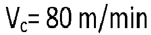
Table 6 Hc (kA/m) weight specific magnetic saturation magnetism (10-6Tm3/kg) Area fraction of abnormal WC grains Gamma phase distribution (N) Invention 214.37 12.7 0.0197 40.0 Comparative 2 13.89 13.0 0.0480 84.3 - The cutting tools from Examples 4 and 5 were also tested in a longitudinal turning operation in steel, SS1312 with a cutting fluid. The following parameters were used:


- Number of tested cutting edges was 15.
- The tool life criterion was edge breakage.
- The results are displayed in Table 7.
Table 7 Time to first break (min) Invention 20.75 Comparative 2 0.50 - The results show that the time to first break of a cutting edge (out of 15 tested edges) has been increased. In the
Figure 2 , where the results of all 15 edges has been shown, it can be seen that forInvention 2, a large number of cutting edges breaks within seconds from each other, whereas the tool life forComparative 2, has a more scattered look. - The cutting tools from Examples 4 and 5 were also tested in a turning operation in steel, SS1672 with a cutting fluid. The following parameters were used:


- Number of tested cutting edges was 3. The edges were investigated after 7, 8 and 9 cycles respectively, and the wear was classified as good, i.e. not much wear, small frittering and then chipping of the cutting edge.
- The results are shown in Table 8.
Table 8 After 7 cycles After 8 cycles After 9 cycles Invention 2 ok ok Small frittering Chipping Chipping Chipping ok Small frittering Chipping Comparative 2 Chipping Chipping Chipping Small frittering Chipping Chipping Small frittering Small frittering Chipping - It can clearly be seen that
Invention 2 has an increased resistance against chipping thanComparative 1. - Cemented carbide substrates were manufactured by first pre-milling recycled cemented carbide material (PRZ) together with (Ta,Nb)C, (Ti,W)C, Ti(C,N) in a milling liquid of ethanol and water (9 wt% water). The ratio between powder and milling liquid was 232kg powder/80 L milling liquid in an agitated mill called LMZ10 from Netzsch which is a horizontal agitated mill where the slurry is circulating between the milling chamber and a holding tank. The slurry was milled at 650 rpm to an accumulated energy of 30 kWh.
- The amount of PRZ, i.e. recycled material is 20 wt% of the total powder weight. In Table 10, the composition in wt% for the PRZ used is shown, batch no. 828. The rest of the raw materials are added in such amounts so that the composition in Table 9 is obtained.
- After the pre-milling step, the WC, Co powders and PEG (poly ethylene glycol),were added to the slurry and milling liquid was added the slurry so that 800 kg powder/160 L milling liquid and all powders was then milled at 650 rpm together to an accumulated energy of 90kWh.
- The amount of PEG was 2 wt% of the total dry powder weight (PEG not included in the total dry powder weight).
- The WC powder was a high temperature carburized WC called HTWC040 purchased from Wolfram Bergbau und Hütten AG.
- The slurry was then spray dried into agglomerates which were then subjected to a pressing operation in a hydraulic press from Fette to form green bodies.
- The green bodies were then sintered by first performing dewaxing in H2 at up to 450°C, vacuum heating up to 1350°C. After that, a protecting atmosphere of flowing 20 mbar Ar and 20 mbar CO is introduced and then maintaining the temperature at 1450°C for 1h.
- The cemented carbide achieved is herein after denoted Invention 3.
- For comparison, a substrate was manufactured by first manufacture cemented carbide substrate by milling all raw material powders in a conventional ball mill for 11 h, i.e. no pre-milling is performed.
- The raw materials were the same as in for Invention 3, with the differences that 15 wt % of the total powder weight of another batch of PRZ was used, batch 757, see Table 10, and that a conventional WC (not high temperature carburized) was used with an average particle size (FSSS) after ASTM-milling of 7.0 µm.
- The amounts of the other raw materials were so that the composition according to Table 9 was achieved.
- The cemented carbide achieved is herein after denoted Comparative 3.
Table 9 Co (wt%) NbC (wt%) TaC (wt%) TiC (wt%) TiN (wt%) WC Invention 3 10.00 1.35 3.55 2.62 0.38 Balance Comparative 3 10.00 1.35 3.55 2.56 0.44 Balance Table 10 Batch W Co Nb Ta Ti Cr Zr V Zn C N O 828 81.5 8.83 0.66 1.58 1.04 0.079 0.022 0.007 0.001 5.73 0.06 0.17 757 82.1 7.99 0.62 1.68 1.31 0.13 0.045 0.012 0.001 5.74 0.06 0.22 - The rest of the PRZ-powder (up to 100%) is trace amounts of Fe, Ni and Al.
- The slurry was then spray dried into agglomerates which were then subjected to a pressing operation in hydraulic press from Fette to form green bodies.
- The achieved materials, Invention 3 and Comparative 3, both have a binder phase enriched surface zone depleted from gamma phase, with a thickness of 22 and 23 µm respectively.
- The microstructure of the sintered materials was analyzed in the same way as in Example 2.
- The results from the measurements can be seen in Table 11 below.
- In Table 11, the Coercivity (Hc) and the weight specific magnetic saturation magnetism is also given.
Table 11 Hc (kA/m) weight specific magnetic saturation magnetism (10-6Tm3/kg) Area fraction of abnormal WC grains Gamma phase distribution (N) Invention 211.66 16.9 0.0139 66.6 Comparative 2 11.55 16.5 0.0458 108.4 - The inserts made according to Example 9, Invention 3 and Comparative 3, were both coated with the same CVD coating comprising a TiCN layer and an α-Al2O3 layer deposited using conventional techniques. The coated inserts were tested in a facing operation under dry conditions. The work piece material was steel, SS2541, with the following conditions:
Vc 160 m/min f 0.3 mm/rev ap 2 mm
The results are shown in Table 12.Table 12 Average Tool Life (min) Invention 3 91 Comparative 3 53
Claims (9)
- A cutting tool comprising a cemented carbide substrate comprising WC, a metallic binder phase and gamma phase, where the cemented carbide has a well distributed gamma phase so that N is less than 80, where


where the area fraction obtained from EBSD analysis of abnormal WC grains defined as
- A cutting tool according to claim 1 wherein the amount of gamma phase is between 3 to 25 vol%.
- A cutting tool according to any of the preceding claims wherein the gamma phase distribution given by N is between 15 and 75.
- A cutting tool according to any of the preceding claims wherein the area fraction of abnormal WC grains is between 0 and 0.025.
- A cutting tool according to any of the preceding claims wherein the amount of metallic binder phase is 2 to 20 wt %.
- A cutting tool according to any of the preceding claims wherein the amount of metallic binder phase is Co.
- A cutting tool according to any of the preceding claims wherein the cemented carbide substrate comprises a binder phase enriched surface zone depleted of gamma phase where the thickness of the surface zone is between 10 and 35 µm.
- A cutting tool according to any of the preceding claims wherein the gamma phase is a solid solution of cubic carbides and/or carbonitrides, (W,M)C or (W,M)(C,N), wherein M is one or more of Ti, Ta, Nb, Hf, Zr, Cr and V.
- A cutting tool according to any of the preceding claims wherein the cemented carbide substrate is provided with a coating.
Priority Applications (9)
| Application Number | Priority Date | Filing Date | Title |
|---|---|---|---|
| EP17158407.1A EP3366795A1 (en) | 2017-02-28 | 2017-02-28 | Cutting tool |
| BR112019017703-5A BR112019017703B1 (en) | 2017-02-28 | 2018-02-27 | SNIPPING TOOL |
| JP2019546800A JP7127050B2 (en) | 2017-02-28 | 2018-02-27 | Cutting tools |
| RU2019126941A RU2758426C2 (en) | 2017-02-28 | 2018-02-27 | Cutting tool |
| CN201880009761.XA CN110268080B (en) | 2017-02-28 | 2018-02-27 | cutting tools |
| EP18708388.6A EP3589767B1 (en) | 2017-02-28 | 2018-02-27 | Cutting tool |
| PCT/EP2018/054798 WO2018158243A1 (en) | 2017-02-28 | 2018-02-27 | Cutting tool |
| KR1020197023988A KR102449638B1 (en) | 2017-02-28 | 2018-02-27 | cutting tool |
| US16/487,128 US11261510B2 (en) | 2017-02-28 | 2018-02-27 | Cutting tool |
Applications Claiming Priority (1)
| Application Number | Priority Date | Filing Date | Title |
|---|---|---|---|
| EP17158407.1A EP3366795A1 (en) | 2017-02-28 | 2017-02-28 | Cutting tool |
Publications (1)
| Publication Number | Publication Date |
|---|---|
| EP3366795A1 true EP3366795A1 (en) | 2018-08-29 |
Family
ID=58192183
Family Applications (2)
| Application Number | Title | Priority Date | Filing Date |
|---|---|---|---|
| EP17158407.1A Withdrawn EP3366795A1 (en) | 2017-02-28 | 2017-02-28 | Cutting tool |
| EP18708388.6A Active EP3589767B1 (en) | 2017-02-28 | 2018-02-27 | Cutting tool |
Family Applications After (1)
| Application Number | Title | Priority Date | Filing Date |
|---|---|---|---|
| EP18708388.6A Active EP3589767B1 (en) | 2017-02-28 | 2018-02-27 | Cutting tool |
Country Status (8)
| Country | Link |
|---|---|
| US (1) | US11261510B2 (en) |
| EP (2) | EP3366795A1 (en) |
| JP (1) | JP7127050B2 (en) |
| KR (1) | KR102449638B1 (en) |
| CN (1) | CN110268080B (en) |
| BR (1) | BR112019017703B1 (en) |
| RU (1) | RU2758426C2 (en) |
| WO (1) | WO2018158243A1 (en) |
Cited By (3)
| Publication number | Priority date | Publication date | Assignee | Title |
|---|---|---|---|---|
| CN109136710A (en) * | 2018-09-14 | 2019-01-04 | 长沙众鑫达工具有限公司 | A kind of hard alloy and preparation method thereof |
| CN109280837A (en) * | 2018-10-31 | 2019-01-29 | 长沙众鑫达工具有限公司 | A kind of hard alloy cutter and preparation method thereof |
| US20220016715A1 (en) * | 2019-10-25 | 2022-01-20 | Sumitomo Electric Industries, Ltd. | Cemented carbide and cutting tool including same as substrate |
Families Citing this family (2)
| Publication number | Priority date | Publication date | Assignee | Title |
|---|---|---|---|---|
| CN114000085B (en) * | 2021-09-17 | 2023-06-02 | 崇义章源钨业股份有限公司 | Titanium carbonitride-based thermal spraying powder and preparation method and application thereof |
| MX2024008948A (en) * | 2022-01-21 | 2024-07-29 | Hyperion Materials & Tech Inc | Cemented carbide compositions. |
Citations (4)
| Publication number | Priority date | Publication date | Assignee | Title |
|---|---|---|---|---|
| US20020114981A1 (en) * | 2000-12-19 | 2002-08-22 | Gunilla Andersson | Coated cemented carbide cutting tool insert |
| US20050126336A1 (en) * | 2003-10-23 | 2005-06-16 | Sandvik Ab | Cemented carbide and method of making the same |
| EP2032731A1 (en) * | 2006-06-15 | 2009-03-11 | Sandvik Intellectual Property AB | Cemented carbide with refined structure |
| US20150063930A1 (en) * | 2011-12-21 | 2015-03-05 | Sandvik Intellectual Property Ab | Method of making a cemented carbide |
Family Cites Families (11)
| Publication number | Priority date | Publication date | Assignee | Title |
|---|---|---|---|---|
| SE446195B (en) * | 1984-11-13 | 1986-08-18 | Santrade Ltd | Carbide rod for drilling rock and the like |
| SE9200530D0 (en) * | 1992-02-21 | 1992-02-21 | Sandvik Ab | HARD METAL WITH BINDING PHASE ENRICHED SURFACE |
| SE9802487D0 (en) | 1998-07-09 | 1998-07-09 | Sandvik Ab | Cemented carbide insert with binder phase enriched surface zone |
| SE513177C2 (en) | 1999-01-14 | 2000-07-24 | Sandvik Ab | Methods of making cemented carbide with a bimodal grain size distribution and containing grain growth inhibitors |
| CA2404294A1 (en) * | 2000-03-24 | 2001-10-04 | Kennametal Inc. | Cemented carbide tool and method of making |
| SE0103970L (en) | 2001-11-27 | 2003-05-28 | Seco Tools Ab | Carbide metal with binder phase enriched surface zone |
| JP4446469B2 (en) * | 2004-03-12 | 2010-04-07 | 住友電工ハードメタル株式会社 | Coated cutting tool |
| SE527906C2 (en) * | 2004-06-24 | 2006-07-04 | Sandvik Intellectual Property | Coated cemented carbide cutter especially intended for turning stainless steel |
| SE0700602L (en) | 2007-03-13 | 2008-09-14 | Sandvik Intellectual Property | Carbide inserts and method of manufacturing the same |
| US8834594B2 (en) | 2011-12-21 | 2014-09-16 | Kennametal Inc. | Cemented carbide body and applications thereof |
| WO2017148885A1 (en) | 2016-02-29 | 2017-09-08 | Sandvik Intellectual Property Ab | Cemented carbide with alternative binder |
-
2017
- 2017-02-28 EP EP17158407.1A patent/EP3366795A1/en not_active Withdrawn
-
2018
- 2018-02-27 EP EP18708388.6A patent/EP3589767B1/en active Active
- 2018-02-27 BR BR112019017703-5A patent/BR112019017703B1/en active IP Right Grant
- 2018-02-27 JP JP2019546800A patent/JP7127050B2/en active Active
- 2018-02-27 WO PCT/EP2018/054798 patent/WO2018158243A1/en not_active Ceased
- 2018-02-27 US US16/487,128 patent/US11261510B2/en active Active
- 2018-02-27 CN CN201880009761.XA patent/CN110268080B/en active Active
- 2018-02-27 RU RU2019126941A patent/RU2758426C2/en active
- 2018-02-27 KR KR1020197023988A patent/KR102449638B1/en active Active
Patent Citations (4)
| Publication number | Priority date | Publication date | Assignee | Title |
|---|---|---|---|---|
| US20020114981A1 (en) * | 2000-12-19 | 2002-08-22 | Gunilla Andersson | Coated cemented carbide cutting tool insert |
| US20050126336A1 (en) * | 2003-10-23 | 2005-06-16 | Sandvik Ab | Cemented carbide and method of making the same |
| EP2032731A1 (en) * | 2006-06-15 | 2009-03-11 | Sandvik Intellectual Property AB | Cemented carbide with refined structure |
| US20150063930A1 (en) * | 2011-12-21 | 2015-03-05 | Sandvik Intellectual Property Ab | Method of making a cemented carbide |
Non-Patent Citations (5)
| Title |
|---|
| "Cubic carbide phase, TiC, 77 reflectors", J. MATTER. CHEM. [JMACEP, vol. 11, 2001, pages 2335 - 2339 |
| 50 REFLECTORS, FIZ. MET. METALLOVED, [FMMTAK, vol. 26, 1968, pages 140 - 143 |
| 59 REFLECTORS, ACTA CRYSTALLOGR., [ACCRA9, vol. 14, 1961, pages 200 - 201 |
| 68 REFLECTORS, Z. ANGEW. PHYS., [ZAPHAX, vol. 23, 1967, pages 245 - 249 |
| IGOR KONYASHIN ED - SARIN ET AL: "1.15 - Cemented Carbides for Mining, Construction and Wear Parts", 1 January 2014 (2014-01-01), XP009501489, ISBN: 978-0-08-096528-4, Retrieved from the Internet <URL:https://www.sciencedirect.com/science/article/pii/B9780080965277000155#> [retrieved on 20140319] * |
Cited By (4)
| Publication number | Priority date | Publication date | Assignee | Title |
|---|---|---|---|---|
| CN109136710A (en) * | 2018-09-14 | 2019-01-04 | 长沙众鑫达工具有限公司 | A kind of hard alloy and preparation method thereof |
| CN109280837A (en) * | 2018-10-31 | 2019-01-29 | 长沙众鑫达工具有限公司 | A kind of hard alloy cutter and preparation method thereof |
| US20220016715A1 (en) * | 2019-10-25 | 2022-01-20 | Sumitomo Electric Industries, Ltd. | Cemented carbide and cutting tool including same as substrate |
| US12005507B2 (en) * | 2019-10-25 | 2024-06-11 | Sumitomo Electric Industries, Ltd. | Cemented carbide and cutting tool including same as substrate |
Also Published As
| Publication number | Publication date |
|---|---|
| CN110268080B (en) | 2022-10-14 |
| US20210140018A1 (en) | 2021-05-13 |
| JP7127050B2 (en) | 2022-08-29 |
| US11261510B2 (en) | 2022-03-01 |
| BR112019017703A2 (en) | 2020-03-31 |
| WO2018158243A1 (en) | 2018-09-07 |
| EP3589767B1 (en) | 2023-12-20 |
| EP3589767A1 (en) | 2020-01-08 |
| KR102449638B1 (en) | 2022-09-29 |
| RU2019126941A3 (en) | 2021-05-24 |
| RU2758426C2 (en) | 2021-10-28 |
| BR112019017703B1 (en) | 2023-12-19 |
| CN110268080A (en) | 2019-09-20 |
| KR20190124216A (en) | 2019-11-04 |
| JP2020514088A (en) | 2020-05-21 |
| RU2019126941A (en) | 2021-03-30 |
Similar Documents
| Publication | Publication Date | Title |
|---|---|---|
| EP3589768B1 (en) | Coated cutting tool | |
| EP3589767B1 (en) | Cutting tool | |
| EP3478874B1 (en) | Cvd coated cutting tool | |
| EP3492627B1 (en) | Coated cutting tool | |
| EP3342511B1 (en) | Coated surface cutting tool and manufacturing method therefor | |
| US11590572B2 (en) | Cutting tool | |
| EP3360630B1 (en) | Surface-coated cutting tool | |
| EP3393703B1 (en) | Cutting tool | |
| JP2015163423A (en) | Surface coated cutting tool whose hard coating layer exerts excellent chipping resistance in high-speed intermittent cutting work | |
| EP3505278A1 (en) | Surface coated cutting tool and manufacturing method thereof | |
| EP3505279B1 (en) | Surface-coated cutting tool and method for manufacturing the same | |
| JP6850995B2 (en) | Surface coating cutting tool | |
| JP7453616B2 (en) | surface coated cutting tools | |
| JP7217866B2 (en) | surface coated cutting tools | |
| EP4173746B1 (en) | Cutting tool | |
| EP4471182A1 (en) | A coated cutting tool | |
| EP4471183A1 (en) | A coated cutting tool |
Legal Events
| Date | Code | Title | Description |
|---|---|---|---|
| PUAI | Public reference made under article 153(3) epc to a published international application that has entered the european phase |
Free format text: ORIGINAL CODE: 0009012 |
|
| STAA | Information on the status of an ep patent application or granted ep patent |
Free format text: STATUS: THE APPLICATION HAS BEEN PUBLISHED |
|
| AK | Designated contracting states |
Kind code of ref document: A1 Designated state(s): AL AT BE BG CH CY CZ DE DK EE ES FI FR GB GR HR HU IE IS IT LI LT LU LV MC MK MT NL NO PL PT RO RS SE SI SK SM TR |
|
| AX | Request for extension of the european patent |
Extension state: BA ME |
|
| STAA | Information on the status of an ep patent application or granted ep patent |
Free format text: STATUS: REQUEST FOR EXAMINATION WAS MADE |
|
| 17P | Request for examination filed |
Effective date: 20190228 |
|
| RBV | Designated contracting states (corrected) |
Designated state(s): AL AT BE BG CH CY CZ DE DK EE ES FI FR GB GR HR HU IE IS IT LI LT LU LV MC MK MT NL NO PL PT RO RS SE SI SK SM TR |
|
| STAA | Information on the status of an ep patent application or granted ep patent |
Free format text: STATUS: THE APPLICATION IS DEEMED TO BE WITHDRAWN |
|
| 18D | Application deemed to be withdrawn |
Effective date: 20190301 |