EP3366615B1 - Device for transportation, separation and orientation of cuvettes - Google Patents
Device for transportation, separation and orientation of cuvettes Download PDFInfo
- Publication number
- EP3366615B1 EP3366615B1 EP18156691.0A EP18156691A EP3366615B1 EP 3366615 B1 EP3366615 B1 EP 3366615B1 EP 18156691 A EP18156691 A EP 18156691A EP 3366615 B1 EP3366615 B1 EP 3366615B1
- Authority
- EP
- European Patent Office
- Prior art keywords
- cuvettes
- head
- cuvette
- auger
- rotating
- Prior art date
- Legal status (The legal status is an assumption and is not a legal conclusion. Google has not performed a legal analysis and makes no representation as to the accuracy of the status listed.)
- Not-in-force
Links
Images




Classifications
-
- B—PERFORMING OPERATIONS; TRANSPORTING
- B01—PHYSICAL OR CHEMICAL PROCESSES OR APPARATUS IN GENERAL
- B01L—CHEMICAL OR PHYSICAL LABORATORY APPARATUS FOR GENERAL USE
- B01L99/00—Subject matter not provided for in other groups of this subclass
-
- B—PERFORMING OPERATIONS; TRANSPORTING
- B01—PHYSICAL OR CHEMICAL PROCESSES OR APPARATUS IN GENERAL
- B01L—CHEMICAL OR PHYSICAL LABORATORY APPARATUS FOR GENERAL USE
- B01L9/00—Supporting devices; Holding devices
-
- B—PERFORMING OPERATIONS; TRANSPORTING
- B65—CONVEYING; PACKING; STORING; HANDLING THIN OR FILAMENTARY MATERIAL
- B65G—TRANSPORT OR STORAGE DEVICES, e.g. CONVEYORS FOR LOADING OR TIPPING, SHOP CONVEYOR SYSTEMS OR PNEUMATIC TUBE CONVEYORS
- B65G33/00—Screw or rotary spiral conveyors
- B65G33/02—Screw or rotary spiral conveyors for articles
-
- B—PERFORMING OPERATIONS; TRANSPORTING
- B65—CONVEYING; PACKING; STORING; HANDLING THIN OR FILAMENTARY MATERIAL
- B65G—TRANSPORT OR STORAGE DEVICES, e.g. CONVEYORS FOR LOADING OR TIPPING, SHOP CONVEYOR SYSTEMS OR PNEUMATIC TUBE CONVEYORS
- B65G33/00—Screw or rotary spiral conveyors
- B65G33/02—Screw or rotary spiral conveyors for articles
- B65G33/04—Screw or rotary spiral conveyors for articles conveyed between a single screw and guiding means
-
- B—PERFORMING OPERATIONS; TRANSPORTING
- B65—CONVEYING; PACKING; STORING; HANDLING THIN OR FILAMENTARY MATERIAL
- B65G—TRANSPORT OR STORAGE DEVICES, e.g. CONVEYORS FOR LOADING OR TIPPING, SHOP CONVEYOR SYSTEMS OR PNEUMATIC TUBE CONVEYORS
- B65G47/00—Article or material-handling devices associated with conveyors; Methods employing such devices
- B65G47/02—Devices for feeding articles or materials to conveyors
- B65G47/04—Devices for feeding articles or materials to conveyors for feeding articles
- B65G47/12—Devices for feeding articles or materials to conveyors for feeding articles from disorderly-arranged article piles or from loose assemblages of articles
- B65G47/14—Devices for feeding articles or materials to conveyors for feeding articles from disorderly-arranged article piles or from loose assemblages of articles arranging or orientating the articles by mechanical or pneumatic means during feeding
- B65G47/1407—Devices for feeding articles or materials to conveyors for feeding articles from disorderly-arranged article piles or from loose assemblages of articles arranging or orientating the articles by mechanical or pneumatic means during feeding the articles being fed from a container, e.g. a bowl
- B65G47/1442—Devices for feeding articles or materials to conveyors for feeding articles from disorderly-arranged article piles or from loose assemblages of articles arranging or orientating the articles by mechanical or pneumatic means during feeding the articles being fed from a container, e.g. a bowl by means of movement of the bottom or a part of the wall of the container
- B65G47/1471—Movement in one direction, substantially outwards
-
- B—PERFORMING OPERATIONS; TRANSPORTING
- B65—CONVEYING; PACKING; STORING; HANDLING THIN OR FILAMENTARY MATERIAL
- B65G—TRANSPORT OR STORAGE DEVICES, e.g. CONVEYORS FOR LOADING OR TIPPING, SHOP CONVEYOR SYSTEMS OR PNEUMATIC TUBE CONVEYORS
- B65G47/00—Article or material-handling devices associated with conveyors; Methods employing such devices
- B65G47/22—Devices influencing the relative position or the attitude of articles during transit by conveyors
- B65G47/24—Devices influencing the relative position or the attitude of articles during transit by conveyors orientating the articles
-
- G—PHYSICS
- G01—MEASURING; TESTING
- G01N—INVESTIGATING OR ANALYSING MATERIALS BY DETERMINING THEIR CHEMICAL OR PHYSICAL PROPERTIES
- G01N35/00—Automatic analysis not limited to methods or materials provided for in any single one of groups G01N1/00 - G01N33/00; Handling materials therefor
- G01N35/02—Automatic analysis not limited to methods or materials provided for in any single one of groups G01N1/00 - G01N33/00; Handling materials therefor using a plurality of sample containers moved by a conveyor system past one or more treatment or analysis stations
- G01N35/04—Details of the conveyor system
- G01N2035/0401—Sample carriers, cuvettes or reaction vessels
-
- G—PHYSICS
- G01—MEASURING; TESTING
- G01N—INVESTIGATING OR ANALYSING MATERIALS BY DETERMINING THEIR CHEMICAL OR PHYSICAL PROPERTIES
- G01N35/00—Automatic analysis not limited to methods or materials provided for in any single one of groups G01N1/00 - G01N33/00; Handling materials therefor
- G01N35/02—Automatic analysis not limited to methods or materials provided for in any single one of groups G01N1/00 - G01N33/00; Handling materials therefor using a plurality of sample containers moved by a conveyor system past one or more treatment or analysis stations
- G01N35/04—Details of the conveyor system
- G01N2035/0401—Sample carriers, cuvettes or reaction vessels
- G01N2035/0406—Individual bottles or tubes
-
- G—PHYSICS
- G01—MEASURING; TESTING
- G01N—INVESTIGATING OR ANALYSING MATERIALS BY DETERMINING THEIR CHEMICAL OR PHYSICAL PROPERTIES
- G01N35/00—Automatic analysis not limited to methods or materials provided for in any single one of groups G01N1/00 - G01N33/00; Handling materials therefor
- G01N35/02—Automatic analysis not limited to methods or materials provided for in any single one of groups G01N1/00 - G01N33/00; Handling materials therefor using a plurality of sample containers moved by a conveyor system past one or more treatment or analysis stations
- G01N35/04—Details of the conveyor system
- G01N2035/0474—Details of actuating means for conveyors or pipettes
- G01N2035/0482—Transmission
- G01N2035/0487—Helix or lead screw
-
- G—PHYSICS
- G01—MEASURING; TESTING
- G01N—INVESTIGATING OR ANALYSING MATERIALS BY DETERMINING THEIR CHEMICAL OR PHYSICAL PROPERTIES
- G01N35/00—Automatic analysis not limited to methods or materials provided for in any single one of groups G01N1/00 - G01N33/00; Handling materials therefor
- G01N35/02—Automatic analysis not limited to methods or materials provided for in any single one of groups G01N1/00 - G01N33/00; Handling materials therefor using a plurality of sample containers moved by a conveyor system past one or more treatment or analysis stations
- G01N35/04—Details of the conveyor system
Definitions
- the invention relates to a system and a method for transportation, separation and orientation in a head up position of cuvettes.
- the invention also relates to using the system or the method for transportation, separation and orientation in head up position of the cuvettes.
- a device that is to be set up between a bulk of cuvettes and the fully automated analyzer system has to fulfil three major functions: transportation of cuvettes, separation of cuvettes and orientation of cuvettes.
- modules In cuvette loading modules of the state of the art, several modules are necessary which transport, separate or orientate the cuvettes in order to provide the fully automated analyzer system with the cuvettes.
- modules like chains, apron conveyers or belts are used to transport the cuvettes.
- sub modules are necessary, for example an oscillating bowl or sliding profiles to separate and orientate the cuvettes.
- Cuvette loading modules of the state of the art are very complex because they contain many components. Such loading modules are expensive and maintenance intensive. Often, the loading modules require several drives, motors and moveable parts, which need to harmonize to each other. This in turn often causes transport jams during the operation of the loading module.
- EP 2 642 300 A1 discloses an embodiment of a transport system configured to transport a receptacle which accommodates an upright sample holder containing a sample, characterized by comprising, a screw comprising a rotatable shaft disposed along a predetermined transport path and a helical ridge protruding outward from an outer peripheral surface of the shaft, and a drive unit configured to rotate the screw.
- the device disclosed in this document is suitable for transporting a receptacle, but not for orientating receptacles that are present in various orientations.
- JP 201217816 A is a container delivery device disclosed including a screw 2 having a spiral groove that is formed at an equal pitch and which holds and conveys a syringe in the groove.
- Upper and lower elevating and lowering guides 30 and 32 guide the side surface of the syringe that is held in the groove of the screw.
- the device disclosed in this document is suitable for transporting a receptacle, but not for orientating receptacles that are present in various orientations.
- Document US 2012/055756 A1 discloses an apparatus for sorting vials and small containers.
- the apparatus of this document comprises at least one auger with a plurality of top recesses and a plurality of side recesses. Vials are placed into the apparatus and fall into the top recesses. As vials fall into the top recesses, the vials are transported through the apparatus by the rotation of the auger. If a vial does not fall into a top recess, it is diverted to a top recess, or to an agitation conveyor that transports the vial to a diverter to be diverted back to an auger. Vials within the top recesses are ejected into vertical alignment so that the vials are sorted and oriented properly for packaging
- the devices disclosed in the prior art comprise complex mechanical components are not suitable for orientating cuvettes for instance in a desired orientation. Thus, there is a need for such a device.
- a device for transportation, separation and orientation in a head up position of cuvettes comprising a pipe, an auger, a motor, a guiding plate and a slide rail.
- a guiding plate is arranged parallel to the rotating auger.
- the rotating auger comprises a core diameter and a thread flank diameter and the thread flank diameter may be larger than the core diameter, and a centre of gravity of a cuvette in a head up or head down position which is to be hold and thereby transported lies within the rotating auger.
- a system according to claim 1 is further provided for transportation, separation and orientation in a head up position of cuvettes, which comprises the above device and further at least one cuvette.
- the at least one cuvette comprises a head part and a bottom part and the head part of the cuvette may comprise an opening and a rim at least partially surrounding the opening, wherein the rim extends over the opening at least on two opposite sides of opening so that the head part of the cuvette has a greater outer width than the bottom part of the cuvette.
- the rotating auger of the system comprises at least one pitch and at least one coil and the length of the at least one pitch is at least the length of the cuvette.
- the at least one pitch may be angled with respect to the at least one coil.
- the opening has a rectangular shape.
- the system may further comprise at least one of a filling funnel and a sub module.
- the slide rail comprises two parallel rails and the distance between the two parallel rails is smaller than the outer width of the head part of the cuvette.
- a method for transportation, separation and orientation in a head up position of cuvettes is provided according to claim 5.
- the at least one cuvette is transported through a pipe from the rotating auger to the slide rail and further from the slide rail to a sub module.
- the cuvettes which are not transported in a head up or head down position, may fall back into the multitudes of cuvettes.
- the cuvettes which are not transported in a head up or head down position may fall back by the use of wipers or compressed air.
- the multitude of cuvettes is present in a filling funnel.
- a device for transportation, separation and orientation in a head up position of cuvettes wherein the device comprises a pipe, a rotating auger, a motor, guiding plate and a slide rail.
- This device has the advantage that it does not comprise many components. Therefore, the device is not complex, the device is inexpensive and the device requires low maintenance. Transport jams during the operation of the device can be avoided.
- the motor may be a single motor.
- the device can fulfil three major functions within one and the same device: transportation, separation and orientation in a head up position of cuvettes.
- cuvette loading modules of the state of the art usually contain many components.
- a cuvette loading module of the state of the art is illustrated in Fig. 1.
- Figure 1 shows a filling funnel 11, which comprises the cuvettes that are to be transported.
- a transport chain 12 is shown which transports the cuvettes from the filling funnel to an oscillating bowl 13.
- the oscillating bowl is necessary to separate and orientate the cuvettes.
- two components are thus required to transport, separate and orientate the cuvettes: a transport chain and an oscillating bowl.
- the present invention avoids the requirement of too many components and provides a device being part of a system which can transport, separate and orientate cuvettes within one device.
- Figure 2 represents such a device being part of a system for transportation, separation and orientation in a head up position of cuvettes according to the present invention.
- the cuvettes are present in a filling funnel 21 as bulk material.
- An auger 22 transports the cuvettes along a guiding plate 28 of a pipe 23.
- the cuvettes are hold by the rotating auger 22 and thereby transported upwards, i. e. away from the filling funnel 21.
- the cuvettes are orientated in head up or head down position.
- Head up or head down position of the cuvettes means that the cuvettes are orientated perpendicular to the diameter of the auger, i. e. the axis connecting the head part of a cuvette and the bottom part of a cuvette is perpendicular to the core diameter of the auger.
- Cuvettes have an opening which is determined as the head part of the cuvette.
- Head up position of the cuvette therefore means that the head part of the cuvette is closer to the upper area of the device and the bottom part of the cuvette is closer to the lower part of the device.
- Head down position of the cuvette in turn means that the bottom part of the cuvette is closer to the upper area of the device and the head part of the cuvette is closer to the bottom area of the device.
- Incorrectly orientated cuvettes 25 fall back down into the filling funnel 21. Incorrectly orientated means that the cuvettes are not orientated in a head up or head down position.
- the arrow 26 shows the transport direction of the cuvettes.
- the arrow 27 shows the rotation direction of the auger.
- a guiding plate 28 which may be arranged parallel to the rotating auger, guides the cuvettes from the filling funnel along the transport direction 26 upwards.
- the guiding plate thereby ensures that the cuvettes are transported upwards in a vertical direction. Without a guiding plate, the cuvettes would only rotate with the rotating auger but not transported upwards. In the upper area of the pipe the cuvettes will be transported to a slide rail. The slide rail ensures orientation of the cuvettes in a head up position.
- the device of Fig. 2 only requires one rotating auger 22.
- the cuvettes may further be transported to a sub module.
- a filling funnel is not an essential component of the device.
- Figure 2 merely demonstrates one example where the cuvettes are present in a filling funnel 21.
- the rotating auger 22 can pick up cuvettes from a multitude or bulk of cuvettes and it is irrelevant where the multitude or bulk of cuvettes is placed.
- a system for transportation, separation and orientation in a head up position of cuvettes comprises the device as disclosed above and further at least one cuvette.
- a cuvette that can be transported, separated and orientated by the device as disclosed above and which can be comprised in the system comprises a head part and a bottom part and the head part of the cuvette comprises an opening and a rim at least partially surrounding the opening, wherein the rim extends over the opening at least on two opposite sides of the opening so that the head part of the cuvette has a greater outer width than the bottom part of the cuvette.
- a cuvette is for example shown in the right half of Fig. 3 .
- the opening may have a rectangular shape which is also shown in the right half of Fig. 3 .
- the person ordinarily skilled in the art will be aware that other shapes of the opening are also possible.
- Figure 3 also illustrates the head up 31 and head down 32 orientation of a cuvette.
- the right half of Figure 3 shows the head of the cuvette 33.
- the interaction between the rotating auger and the pipe only allows transportation in two orientations of the cuvettes, that is head up or head down. Cuvettes in all of the other orientations will not be transported because they fall back down into the filling funnel (or any other place where the multitude or bulk of cuvettes is placed).
- the thread flank shape of the auger determines whether the cuvettes will be hold in one of the two orientations (head up 31 or head down 32 position) or whether the cuvettes will fall back into the filling funnel (or any other place where the multitude or bulk of cuvettes is placed).
- Figure 4 also illustrates why the cuvettes can only be transported in a head up or head down position.
- the arrow 41 represents the centre of gravity of each cuvette.
- the centre of gravity has to lie within the rotating auger so that the cuvettes are transported and do not fall back down. It is obvious from Figure 4 that the centre of gravity of the cuvettes lies within the rotating auger as long as the cuvettes are in a head up or head down position. This is the case with the upper two cuvettes.
- the upper two cuvettes are in a head up and head down position, respectively, and their respective centre of gravity lies within the rotating auger.
- the slide rail ensures that all cuvettes are finally orientated in a head up position. Therefore, the device allows transportation, separation and orientation in a head up position of cuvettes.
- the rotating auger comprises at least one pitch 42 and at least one coil 43 as illustrated in Figure 4 .
- a pitch 42 is the distance between two coils 43.
- the length of the at least one pitch 42 is at least the length of the cuvette.
- the at least one pitch 42 may be angled with respect to the at least one coil 43.
- the rotating auger itself may also be angled.
- the coil 43 of the rotating auger further exhibits an upper edge 44, wherein the width of the upper edge 44 can be defined as one half of the difference between the thread flank diameter and the core diameter of the rotating auger.
- the system may further comprise at least one of a filling funnel and a sub module.
- the filling funnel may be of any shape which allows a multitude or bulk of cuvettes to be stored and to be picked up from the auger for transportation, separation and orientation. As discussed above, the multitude or bulk of cuvettes does not need to be placed in a filling funnel.
- Figure 5 shows the upper part of the system, where the cuvettes pass through specific edges so as to then be transported into a slot of a slide rail. The cuvettes are then transported to a sub module.
- the system may comprise the sub module.
- Figure 5A shows the auger transporting cuvettes in a head up or head down position which have been separated.
- Figure 5B the upper part of the device or of the system is shown from a different perspective. The cuvettes pass through specific edges from the auger to the slide rail and are hanging in the slide rail from where they can be transported to a sub module.
- the slide rail may comprise two parallel rails and the distance between the two parallel rails is smaller than the outer width of the head part of the cuvette.
- Figure 6 shows a schematic illustration of such a slide rail.
- the cuvettes will arrive at the slide rail from the upper area of the device or of the system and either be in a head up or head down position.
- the left part of Figure 6 shows that the cuvettes arrive in a head up position and the right part of Figure 6 shows that the cuvettes arrive in a head down position.
- the sub module or any fully automated analyzer system that the cuvettes can be transported to eventually require the cuvettes in a head up position so that they can be filled with liquid.
- the cuvette comprises an opening and a rim 61 at least partially surrounding the opening.
- the rim of the cuvette 61 extends over the opening at least on two opposite sides of the opening so that the head part of the cuvette has a greater outer width than the bottom part of the cuvette.
- Such a cuvette assures that the cuvette will fall down into the slot of the slide rail in a head up position and eventually all cuvettes will be in a head up position.
- a method for transportation, separation and orientation in a head up position of cuvettes comprises the following steps:
- the auger rotates in one direction and thereby allows picking up at least one cuvette from a multitude of cuvettes.
- a multitude of cuvettes means at least two cuvettes and is synonymous with a bulk of cuvettes.
- the longitudinal axis of the rotating auger refers to the axis perpendicular to the diameter of the auger.
- the diameter of the auger comprises an inner (core) and an outer (thread flank) diameter as disclosed above.
- Cuvettes as disclosed above, which are not transported in a head up or head down position fall back into the multitude of cuvettes. They may fall back by the use of wipers or compressed air. However, other methods to aid the incorrectly orientated cuvettes to fall back into the multitude of cuvettes may also be possible.
- the multitude of cuvettes may be present in a filling funnel from where the auger picks up the at least one cuvette from the multitude of cuvettes.
- the person ordinarily skilled in the art will understand that other means for storing the cuvettes are also possible.
- the device and the system can be used for transportation, separation and orientation in a head up position of cuvettes.
- the device and the system are not complex and are of low maintenance. They may require only a single motor which reduces the number of components. No further sub modules for separation or orientation of the cuvettes are required because the device is able to fulfil all three functions of transporting the cuvettes, separating the cuvettes and orientating the cuvettes within one device.
- the device of the instant invention is based on an combination of an angled auger and a slide rail ensuring that cuvettes will be in a head up position after entering the slide rail. The number of mechanical components is thus reduced.
- the device disclosed in document US 2012/055756 A1 is an example of a device known from prior art that comprises complex mechanical parts.
- the device comprises two augers instead of only one auger in addition to several other mechanical parts for transporting closed vessels.
- the device of US 2012/055756 is not only structurally different, but also not suitable for orientating open receptacles like cuvettes or reaction vessels in automated analyser systems.
Landscapes
- Engineering & Computer Science (AREA)
- Mechanical Engineering (AREA)
- Health & Medical Sciences (AREA)
- Chemical & Material Sciences (AREA)
- Clinical Laboratory Science (AREA)
- Chemical Kinetics & Catalysis (AREA)
- Analytical Chemistry (AREA)
- Life Sciences & Earth Sciences (AREA)
- Physics & Mathematics (AREA)
- Biochemistry (AREA)
- General Health & Medical Sciences (AREA)
- General Physics & Mathematics (AREA)
- Immunology (AREA)
- Pathology (AREA)
- Feeding Of Articles To Conveyors (AREA)
- Automatic Analysis And Handling Materials Therefor (AREA)
- Specific Conveyance Elements (AREA)
Description
- The invention relates to a system and a method for transportation, separation and orientation in a head up position of cuvettes. The invention also relates to using the system or the method for transportation, separation and orientation in head up position of the cuvettes.
- When cuvettes are transported from a bulk to a fully automated analyzer system, the fully automated analyzer system requires that the cuvettes are separated as well as orientated in a head up position. Therefore, a device that is to be set up between a bulk of cuvettes and the fully automated analyzer system has to fulfil three major functions: transportation of cuvettes, separation of cuvettes and orientation of cuvettes.
- In cuvette loading modules of the state of the art, several modules are necessary which transport, separate or orientate the cuvettes in order to provide the fully automated analyzer system with the cuvettes. Typically, modules like chains, apron conveyers or belts are used to transport the cuvettes. Further, sub modules are necessary, for example an oscillating bowl or sliding profiles to separate and orientate the cuvettes.
- Cuvette loading modules of the state of the art are very complex because they contain many components. Such loading modules are expensive and maintenance intensive. Often, the loading modules require several drives, motors and moveable parts, which need to harmonize to each other. This in turn often causes transport jams during the operation of the loading module.
-
EP 2 642 300 A1 discloses an embodiment of a transport system configured to transport a receptacle which accommodates an upright sample holder containing a sample, characterized by comprising, a screw comprising a rotatable shaft disposed along a predetermined transport path and a helical ridge protruding outward from an outer peripheral surface of the shaft, and a drive unit configured to rotate the screw. The device disclosed in this document is suitable for transporting a receptacle, but not for orientating receptacles that are present in various orientations. - In
JP 201217816 A guides 30 and 32 guide the side surface of the syringe that is held in the groove of the screw. The device disclosed in this document is suitable for transporting a receptacle, but not for orientating receptacles that are present in various orientations. - Document
US 2012/055756 A1 discloses an apparatus for sorting vials and small containers. The apparatus of this document comprises at least one auger with a plurality of top recesses and a plurality of side recesses. Vials are placed into the apparatus and fall into the top recesses. As vials fall into the top recesses, the vials are transported through the apparatus by the rotation of the auger. If a vial does not fall into a top recess, it is diverted to a top recess, or to an agitation conveyor that transports the vial to a diverter to be diverted back to an auger. Vials within the top recesses are ejected into vertical alignment so that the vials are sorted and oriented properly for packaging - The devices disclosed in the prior art comprise complex mechanical components are not suitable for orientating cuvettes for instance in a desired orientation. Thus, there is a need for such a device.
- It is therefore an object of the present invention to provide a system for transportation, separation and orientation in head up position of cuvettes, wherein the system contains fewer parts than the loading modules of the prior art. It is also an object of the present invention to provide a method for transportation, separation and orientation in a head up position of cuvettes.
- A device for transportation, separation and orientation in a head up position of cuvettes is provided, wherein the device comprises a pipe, an auger, a motor, a guiding plate and a slide rail.
- A guiding plate is arranged parallel to the rotating auger.
- The rotating auger comprises a core diameter and a thread flank diameter and the thread flank diameter may be larger than the core diameter, and a centre of gravity of a cuvette in a head up or head down position which is to be hold and thereby transported lies within the rotating auger.
- A system according to claim 1 is further provided for transportation, separation and orientation in a head up position of cuvettes, which comprises the above device and further at least one cuvette.
- The at least one cuvette comprises a head part and a bottom part and the head part of the cuvette may comprise an opening and a rim at least partially surrounding the opening, wherein the rim extends over the opening at least on two opposite sides of opening so that the head part of the cuvette has a greater outer width than the bottom part of the cuvette. The rotating auger of the system comprises at least one pitch and at least one coil and the length of the at least one pitch is at least the length of the cuvette.
- The at least one pitch may be angled with respect to the at least one coil.
- In one aspect, the opening has a rectangular shape.
- The system may further comprise at least one of a filling funnel and a sub module.
- The slide rail comprises two parallel rails and the distance between the two parallel rails is smaller than the outer width of the head part of the cuvette.
- A method for transportation, separation and orientation in a head up position of cuvettes is provided according to claim 5.
- In another aspect, the at least one cuvette is transported through a pipe from the rotating auger to the slide rail and further from the slide rail to a sub module.
- The cuvettes, which are not transported in a head up or head down position, may fall back into the multitudes of cuvettes.
- The cuvettes, which are not transported in a head up or head down position may fall back by the use of wipers or compressed air.
- In one aspect, the multitude of cuvettes is present in a filling funnel.
- Use of the system or the method is provided for transportation, separation and orientation in head up position of cuvettes.
-
-
Fig. 1 shows a cuvette loading module of the state of the art. -
Fig. 2 shows a device being part of a system according to the present invention for transportation, separation and orientation in a head up position of cuvettes. -
Fig. 3 illustrates the cuvette in a head down and head up position. -
Fig. 4 shows cuvettes being transported by a rotating auger in a head up or head down position. -
Fig. 5 shows the upper area of the device being part of the system according to the present invention. -
Fig. 6 shows a slide rail and cuvettes. - The invention will now be described in detail. Drawings and examples are provided for better illustration of the invention. It will be understood that the embodiments and aspects of the invention described herein are only examples and do not limit the protector's scope of the claims in any way. The invention is defined by the claims and their equivalents. It will be understood that features of one aspect or embodiment of the invention can be combined with the feature of a different aspect or aspects and/or embodiments of the invention.
- A device for transportation, separation and orientation in a head up position of cuvettes is provided, wherein the device comprises a pipe, a rotating auger, a motor, guiding plate and a slide rail. This device has the advantage that it does not comprise many components. Therefore, the device is not complex, the device is inexpensive and the device requires low maintenance. Transport jams during the operation of the device can be avoided. The motor may be a single motor. The device can fulfil three major functions within one and the same device: transportation, separation and orientation in a head up position of cuvettes.
- In contrast, cuvette loading modules of the state of the art usually contain many components. Such a cuvette loading module of the state of the art is illustrated in
Fig. 1. Figure 1 shows a fillingfunnel 11, which comprises the cuvettes that are to be transported. Atransport chain 12 is shown which transports the cuvettes from the filling funnel to anoscillating bowl 13. The oscillating bowl is necessary to separate and orientate the cuvettes. In such a cuvette loading module, two components are thus required to transport, separate and orientate the cuvettes: a transport chain and an oscillating bowl. - The present invention, however, avoids the requirement of too many components and provides a device being part of a system which can transport, separate and orientate cuvettes within one device.
Figure 2 represents such a device being part of a system for transportation, separation and orientation in a head up position of cuvettes according to the present invention. - In
Figure 2 , the cuvettes are present in a fillingfunnel 21 as bulk material. Anauger 22 transports the cuvettes along a guidingplate 28 of apipe 23. The cuvettes are hold by therotating auger 22 and thereby transported upwards, i. e. away from the fillingfunnel 21. At the same time, the cuvettes are orientated in head up or head down position. Head up or head down position of the cuvettes means that the cuvettes are orientated perpendicular to the diameter of the auger, i. e. the axis connecting the head part of a cuvette and the bottom part of a cuvette is perpendicular to the core diameter of the auger. Cuvettes have an opening which is determined as the head part of the cuvette. Head up position of the cuvette therefore means that the head part of the cuvette is closer to the upper area of the device and the bottom part of the cuvette is closer to the lower part of the device. Head down position of the cuvette in turn means that the bottom part of the cuvette is closer to the upper area of the device and the head part of the cuvette is closer to the bottom area of the device. Incorrectly orientatedcuvettes 25 fall back down into the fillingfunnel 21. Incorrectly orientated means that the cuvettes are not orientated in a head up or head down position. Thearrow 26 shows the transport direction of the cuvettes. Thearrow 27 shows the rotation direction of the auger. A guidingplate 28, which may be arranged parallel to the rotating auger, guides the cuvettes from the filling funnel along thetransport direction 26 upwards. The guiding plate thereby ensures that the cuvettes are transported upwards in a vertical direction. Without a guiding plate, the cuvettes would only rotate with the rotating auger but not transported upwards. In the upper area of the pipe the cuvettes will be transported to a slide rail. The slide rail ensures orientation of the cuvettes in a head up position. The device ofFig. 2 only requires one rotatingauger 22. The cuvettes may further be transported to a sub module. - It is to be noted that a filling funnel is not an essential component of the device.
Figure 2 merely demonstrates one example where the cuvettes are present in a fillingfunnel 21. Therotating auger 22 can pick up cuvettes from a multitude or bulk of cuvettes and it is irrelevant where the multitude or bulk of cuvettes is placed. - A system for transportation, separation and orientation in a head up position of cuvettes is also provided. The system comprises the device as disclosed above and further at least one cuvette. One example of a cuvette that can be transported, separated and orientated by the device as disclosed above and which can be comprised in the system comprises a head part and a bottom part and the head part of the cuvette comprises an opening and a rim at least partially surrounding the opening, wherein the rim extends over the opening at least on two opposite sides of the opening so that the head part of the cuvette has a greater outer width than the bottom part of the cuvette. Such a cuvette is for example shown in the right half of
Fig. 3 . In one aspect, the opening may have a rectangular shape which is also shown in the right half ofFig. 3 . However, the person ordinarily skilled in the art will be aware that other shapes of the opening are also possible. -
Figure 3 also illustrates the head up 31 and head down 32 orientation of a cuvette. The right half ofFigure 3 shows the head of thecuvette 33. The interaction between the rotating auger and the pipe only allows transportation in two orientations of the cuvettes, that is head up or head down. Cuvettes in all of the other orientations will not be transported because they fall back down into the filling funnel (or any other place where the multitude or bulk of cuvettes is placed). The thread flank shape of the auger determines whether the cuvettes will be hold in one of the two orientations (head up 31 or head down 32 position) or whether the cuvettes will fall back into the filling funnel (or any other place where the multitude or bulk of cuvettes is placed). -
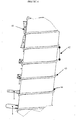
Figure 4 also illustrates why the cuvettes can only be transported in a head up or head down position. Thearrow 41 represents the centre of gravity of each cuvette. The centre of gravity has to lie within the rotating auger so that the cuvettes are transported and do not fall back down. It is obvious fromFigure 4 that the centre of gravity of the cuvettes lies within the rotating auger as long as the cuvettes are in a head up or head down position. This is the case with the upper two cuvettes. The upper two cuvettes are in a head up and head down position, respectively, and their respective centre of gravity lies within the rotating auger. The slide rail ensures that all cuvettes are finally orientated in a head up position. Therefore, the device allows transportation, separation and orientation in a head up position of cuvettes. - A different cuvette would require different diameters of the pipe, of the core diameter of the auger and of the thread flank diameter of the auger. The design of the cuvette and the design of the device therefore have to be coordinated. The rotating auger comprises at least one
pitch 42 and at least onecoil 43 as illustrated inFigure 4 . Apitch 42 is the distance between twocoils 43. The length of the at least onepitch 42 is at least the length of the cuvette. The at least onepitch 42 may be angled with respect to the at least onecoil 43. The rotating auger itself may also be angled. Thecoil 43 of the rotating auger further exhibits anupper edge 44, wherein the width of theupper edge 44 can be defined as one half of the difference between the thread flank diameter and the core diameter of the rotating auger. There is an interrelationship between the width of theupper edge 44 and the angle of thepitch 42 or the angle of the rotating auger. The more angled thepitch 42 or the rotating auger, the less width of theupper edge 44 is required for the cuvettes to be hold in place. - The system may further comprise at least one of a filling funnel and a sub module.
- The filling funnel may be of any shape which allows a multitude or bulk of cuvettes to be stored and to be picked up from the auger for transportation, separation and orientation. As discussed above, the multitude or bulk of cuvettes does not need to be placed in a filling funnel.
-
Figure 5 shows the upper part of the system, where the cuvettes pass through specific edges so as to then be transported into a slot of a slide rail. The cuvettes are then transported to a sub module. The system may comprise the sub module.Figure 5A shows the auger transporting cuvettes in a head up or head down position which have been separated. In the upper right part ofFigure 5A cuvettes hanging in a slide rail are shown. InFigure 5B the upper part of the device or of the system is shown from a different perspective. The cuvettes pass through specific edges from the auger to the slide rail and are hanging in the slide rail from where they can be transported to a sub module. - The slide rail may comprise two parallel rails and the distance between the two parallel rails is smaller than the outer width of the head part of the cuvette.
Figure 6 shows a schematic illustration of such a slide rail. The cuvettes will arrive at the slide rail from the upper area of the device or of the system and either be in a head up or head down position. The left part ofFigure 6 shows that the cuvettes arrive in a head up position and the right part ofFigure 6 shows that the cuvettes arrive in a head down position. The sub module or any fully automated analyzer system that the cuvettes can be transported to eventually require the cuvettes in a head up position so that they can be filled with liquid. The schematic illustration inFig. 6 shows how and why both orientations head up and head down can be used to transport the cuvettes to the slide rail. The cuvette comprises an opening and arim 61 at least partially surrounding the opening. The rim of thecuvette 61 extends over the opening at least on two opposite sides of the opening so that the head part of the cuvette has a greater outer width than the bottom part of the cuvette. Such a cuvette assures that the cuvette will fall down into the slot of the slide rail in a head up position and eventually all cuvettes will be in a head up position. - A method for transportation, separation and orientation in a head up position of cuvettes is also provided. The method comprises the following steps:
- a. picking up at least one cuvette by a rotating auger from a multitude of cuvettes,
- b. separating the at least one cuvette that was picked up from the multitude of cuvettes;
- c. transporting the at least one cuvette in a head up or head down position along a longitudinal axis of the rotating auger through a pipe to a slide rail,
wherein while rotating with the rotating auger the cuvettes are pushed towards a guiding plate, - d. orientating the at least one cuvette in a head up position in the slide rail.
- The method is best illustrated by the above disclosed
Figure 2 . The auger rotates in one direction and thereby allows picking up at least one cuvette from a multitude of cuvettes. A multitude of cuvettes means at least two cuvettes and is synonymous with a bulk of cuvettes. The longitudinal axis of the rotating auger refers to the axis perpendicular to the diameter of the auger. The diameter of the auger comprises an inner (core) and an outer (thread flank) diameter as disclosed above. - Cuvettes, as disclosed above, which are not transported in a head up or head down position fall back into the multitude of cuvettes. They may fall back by the use of wipers or compressed air. However, other methods to aid the incorrectly orientated cuvettes to fall back into the multitude of cuvettes may also be possible.
- The multitude of cuvettes may be present in a filling funnel from where the auger picks up the at least one cuvette from the multitude of cuvettes. The person ordinarily skilled in the art will understand that other means for storing the cuvettes are also possible.
- It has become obvious from above disclosures and figures that the device and the system can be used for transportation, separation and orientation in a head up position of cuvettes. The device and the system are not complex and are of low maintenance. They may require only a single motor which reduces the number of components. No further sub modules for separation or orientation of the cuvettes are required because the device is able to fulfil all three functions of transporting the cuvettes, separating the cuvettes and orientating the cuvettes within one device.
- In contrast to the devices disclosed in the prior art, the device of the instant invention is based on an combination of an angled auger and a slide rail ensuring that cuvettes will be in a head up position after entering the slide rail. The number of mechanical components is thus reduced.
- The device disclosed in document
US 2012/055756 A1 is an example of a device known from prior art that comprises complex mechanical parts. The device comprises two augers instead of only one auger in addition to several other mechanical parts for transporting closed vessels. However, the device ofUS 2012/055756 is not only structurally different, but also not suitable for orientating open receptacles like cuvettes or reaction vessels in automated analyser systems. -
- 11
- Filling funnel
- 12
- Transport chain
- 13
- Oscillating bowl
- 21
- Filling funnel
- 22
- Auger
- 23
- Pipe
- 24
- Separation of the cuvettes along a guiding plate
- 25
- Incorrectly orientated cuvettes
- 26
- Transport direction of the cuvettes
- 27
- Rotation direction of the auger
- 28
- Guiding plate
- 31
- Head up position of the cuvette
- 32
- Head down position of the cuvette
- 33
- Head of the cuvette
- 41
- Centre of gravity of each cuvette
- 42
- Pitch
- 43
- Coil
- 44
- Upper edge of the coil
- 61
- Rim of the cuvette
Claims (11)
- A system for transportation, separation and orientation of cuvettes in a head up position, the system comprisinga. device for transportation, separation and orientation of cuvettes in a head up position, the device comprising a pipe, a motor and a vertically oriented auger (22), angled with respect to the vertical, and a guiding plate (28) that is arranged parallel to the auger (22), wherein the motor is connected with the auger (22) for rotating it, the auger comprising a core diameter and a thread flank diameter and the thread flank diameter is larger than the core diameter, and wherein a center of gravity of a cuvette in a head up or head down position which is to be hold and thereby transported by the auger (22) lies within the thread flank diameter so that they do not fall back and a slide rail with two parallel rails with a distance to one another being smaller than the outer width of a head part of the cuvette is arranged in the upper area of the pipe for taking up the cuvettes in a head up position ; andb. at least one cuvette, wherein the cuvette comprises a head part and a bottom part and the head part of the cuvette comprises an opening and a rim at least partially surrounding the opening, wherein the rim extends over the opening at least on two opposite sides of the opening so that the head part of the cuvette has a greater outer width than the bottom part of the cuvette, and wherein the rotating auger (22) comprises at least one pitch and at least one coil and the length of the at least one pitch is at least the length of the cuvette.
- The system according to claim 1, wherein the at least one pitch is angled with respect to the at least one coil.
- The system according to claim 1 or 2, wherein the opening of the cuvette has a rectangular shape.
- The system according to any one of claims 1 to 3, wherein the system further comprises at least one of a filling funnel and a sub module.
- A method for transportation, separation and orientation of cuvettes in a head up position, the method comprising the following steps:picking up at least one cuvette from a multitude of cuvettes by a vertically oriented auger located inside a pipe (22), angled with respect to the vertical, with a guiding plate (28) of a pipe (23) that is arranged parallel to the rotating auger (22) that is connected to a motor for rotating it, wherein said rotating auger (22) comprises a core diameter and a thread flank diameter and the thread flank diameter is larger than the core diameter, and wherein a centre of gravity of the at least one cuvette in a head up or head down position which is to be hold and thereby transported by the auger (22) lies within the within the thread flank diameter so that the at least one cuvette does not fall back, thereby separating the at least one cuvette that was picked up from the multitude of cuvettes; andtransporting the at least one cuvette in a head up or head down position along a longitudinal axis of the rotating auger (22) to a slide rail,wherein while rotating with the rotating auger (22) the cuvettes are pushed towards a guiding plate, andpassing the cuvettes from the rotating auger (22) to the slide rail; andorientating the at least one cuvette in a head up position in the slide rail with two parallel rails with a distance to one another being smaller than the outer width of a head part of the cuvette is arranged in the upper area of the pipe for taking up the cuvettes in a head up position.
- The method according to claim 5, wherein the at least one cuvette is transported through a pipe from the rotating auger (2) to the slide rail.
- The method according to any one of claim 5 or 6, wherein the at least one cuvette is further transported from the slide rail to a sub module.
- The method according to any one of claims 5 to 7, wherein cuvettes, which are not transported in a head up or head down position fall back into the multitude of cuvettes.
- The method according to claim 8, wherein cuvettes, which are not transported in a head up or head down position fall back by the use of wipers or compressed air.
- The method according to any one of claims 5 to 9, wherein the multitude of cuvettes is present in a filling funnel.
- Use of the system according claim 1 to 4 or the method of claims 5 to 10 for transportation, separation and orientation of cuvettes in a head up position.
Applications Claiming Priority (2)
| Application Number | Priority Date | Filing Date | Title |
|---|---|---|---|
| GB1416687.0A GB2530336A (en) | 2014-09-22 | 2014-09-22 | Device for transportation Separation and Orientation of cuvettes |
| EP15180969.6A EP2998246A1 (en) | 2014-09-22 | 2015-08-13 | Device for transportation, separation and orientation of cuvettes |
Related Parent Applications (2)
| Application Number | Title | Priority Date | Filing Date |
|---|---|---|---|
| EP15180969.6A Division EP2998246A1 (en) | 2014-09-22 | 2015-08-13 | Device for transportation, separation and orientation of cuvettes |
| EP15180969.6A Previously-Filed-Application EP2998246A1 (en) | 2014-09-22 | 2015-08-13 | Device for transportation, separation and orientation of cuvettes |
Publications (2)
| Publication Number | Publication Date |
|---|---|
| EP3366615A1 EP3366615A1 (en) | 2018-08-29 |
| EP3366615B1 true EP3366615B1 (en) | 2021-01-13 |
Family
ID=51869265
Family Applications (2)
| Application Number | Title | Priority Date | Filing Date |
|---|---|---|---|
| EP18156691.0A Not-in-force EP3366615B1 (en) | 2014-09-22 | 2015-08-13 | Device for transportation, separation and orientation of cuvettes |
| EP15180969.6A Withdrawn EP2998246A1 (en) | 2014-09-22 | 2015-08-13 | Device for transportation, separation and orientation of cuvettes |
Family Applications After (1)
| Application Number | Title | Priority Date | Filing Date |
|---|---|---|---|
| EP15180969.6A Withdrawn EP2998246A1 (en) | 2014-09-22 | 2015-08-13 | Device for transportation, separation and orientation of cuvettes |
Country Status (3)
| Country | Link |
|---|---|
| US (1) | US9745140B2 (en) |
| EP (2) | EP3366615B1 (en) |
| GB (1) | GB2530336A (en) |
Families Citing this family (5)
| Publication number | Priority date | Publication date | Assignee | Title |
|---|---|---|---|---|
| DE102015205984A1 (en) * | 2015-04-02 | 2016-10-06 | Krones Aktiengesellschaft | Method and guide system for the transport of containers or container components in industrial plants for container production and / or product filling |
| EP3314269A4 (en) | 2015-06-26 | 2019-01-23 | Abbott Laboratories | Reaction vessel exchanger device for a diagnostic analyzer |
| JP7323546B2 (en) * | 2018-10-10 | 2023-08-08 | 株式会社Lsiメディエンス | cuvette feeder |
| CN115932291A (en) * | 2021-08-13 | 2023-04-07 | 佳能医疗系统株式会社 | Subject inspection apparatus and subject inspection method |
| JP2026016900A (en) * | 2024-07-23 | 2026-02-04 | 株式会社日立ハイテク | Article alignment and transport device |
Family Cites Families (15)
| Publication number | Priority date | Publication date | Assignee | Title |
|---|---|---|---|---|
| US3026991A (en) * | 1959-11-02 | 1962-03-27 | Lewis H Kinsley | Feed screw |
| US3815730A (en) * | 1972-08-02 | 1974-06-11 | T Zwiep | Orienting apparatus and method |
| DE2619950C2 (en) * | 1976-05-06 | 1981-10-22 | Kronseder, Hermann, 8404 Wörth | Device for transferring upright bottles between two synchronously driven bottle handling machines |
| SU1188063A1 (en) * | 1983-10-18 | 1985-10-30 | Предприятие П/Я В-2501 | Orienting device |
| AT388151B (en) * | 1984-12-06 | 1989-05-10 | Gradoboev Vladimir T | DEVICE FOR REMOVING WORKPIECES FROM A PILE FOR FEEDING THESE WORKPIECES TO A DEVICE |
| DE3790963T1 (en) * | 1987-05-29 | 1989-05-24 | Gradoboev Vladimir T | DEVICE FOR EXTRACTING AND CONVEYING INDIVIDUAL PRODUCTS FROM A PILLAGE |
| US5341918A (en) * | 1993-04-16 | 1994-08-30 | Covert William J | Article transfer device |
| GB9411990D0 (en) * | 1994-06-15 | 1994-08-03 | Coca Cola & Schweppes Beverage | Apparatus for handling and/or cleansing tubular articels |
| US6053303A (en) * | 1998-01-21 | 2000-04-25 | Wang; Chao-Yang | Transporting articles |
| FR2864050B1 (en) * | 2003-12-23 | 2007-04-06 | Sidel Sa | PREFORM FEEDING SYSTEM HAVING A DEVICE FOR SELECTIVELY ELIMINATING MALLED POSITIONED PREFORMS |
| JP4829677B2 (en) * | 2006-05-18 | 2011-12-07 | シスメックス株式会社 | Sample analyzer |
| US20120055756A1 (en) * | 2008-09-22 | 2012-03-08 | Reardon Jr Joseph P | Vial sorting apparatus |
| JP5776220B2 (en) * | 2011-02-25 | 2015-09-09 | 澁谷工業株式会社 | Container delivery method and container delivery device |
| JP5514850B2 (en) * | 2012-03-08 | 2014-06-04 | あおい精機株式会社 | Conveying apparatus and conveying method |
| DE102012103079A1 (en) * | 2012-04-10 | 2013-10-10 | Krones Ag | Roller conveyor for plastic preforms |
-
2014
- 2014-09-22 GB GB1416687.0A patent/GB2530336A/en not_active Withdrawn
-
2015
- 2015-08-13 EP EP18156691.0A patent/EP3366615B1/en not_active Not-in-force
- 2015-08-13 US US14/825,512 patent/US9745140B2/en active Active
- 2015-08-13 EP EP15180969.6A patent/EP2998246A1/en not_active Withdrawn
Non-Patent Citations (1)
| Title |
|---|
| None * |
Also Published As
| Publication number | Publication date |
|---|---|
| US9745140B2 (en) | 2017-08-29 |
| GB2530336A (en) | 2016-03-23 |
| EP3366615A1 (en) | 2018-08-29 |
| US20160083195A1 (en) | 2016-03-24 |
| GB201416687D0 (en) | 2014-11-05 |
| EP2998246A1 (en) | 2016-03-23 |
Similar Documents
| Publication | Publication Date | Title |
|---|---|---|
| US9745140B2 (en) | Device for transportation, separation and orientation of cuvettes | |
| US10486889B2 (en) | Drug feeder | |
| US9365308B2 (en) | Medication cassette | |
| US20140353327A1 (en) | Atypical pill dispensing apparatus | |
| CN104237548B (en) | For the treatment of the device of sample hose and method and experimental system | |
| US8403010B2 (en) | Tablet filling device | |
| US11440751B2 (en) | Reaction vessel pickup mechanism, automatic loading device, sample analyzer, and loading method | |
| CN118243940A (en) | Reaction cup automatic loading device and sample analyzer | |
| EP3196655B1 (en) | Laboratory sample container carrier handling apparatus and laboratory system | |
| US12466662B2 (en) | Separating device | |
| US20170254826A1 (en) | Feeding apparatus | |
| CN116457291B (en) | Machines used for orienting and aligning items supplied in bulk. | |
| KR101008348B1 (en) | Package Packing Device | |
| US8011516B2 (en) | Method and device for sorting objects | |
| US9174244B2 (en) | System and apparatus for separating and orienting sample containers | |
| US20030101694A1 (en) | Bottle unpack/repack apparatus and methods | |
| CN108069206B (en) | Automatic sorting, loading and supporting device for materials | |
| CN102431775B (en) | There is sorting and the conveyer device of the outlet of improvement | |
| EP3214450B1 (en) | Transporting device for transporting a laboratory diagnostic vessel carrier | |
| CN214845324U (en) | Reaction cup conveying device | |
| CN116891107B (en) | Feeding mechanism of ice cream production line | |
| US20100163373A1 (en) | Medicament bottle dispenser | |
| CN214730071U (en) | Material conveying device | |
| KR101636355B1 (en) | Cap sorter without power | |
| CN117480095A (en) | Apparatus and method for automatically guiding objects into bins |
Legal Events
| Date | Code | Title | Description |
|---|---|---|---|
| PUAI | Public reference made under article 153(3) epc to a published international application that has entered the european phase |
Free format text: ORIGINAL CODE: 0009012 |
|
| STAA | Information on the status of an ep patent application or granted ep patent |
Free format text: STATUS: THE APPLICATION HAS BEEN PUBLISHED |
|
| AC | Divisional application: reference to earlier application |
Ref document number: 2998246 Country of ref document: EP Kind code of ref document: P |
|
| AK | Designated contracting states |
Kind code of ref document: A1 Designated state(s): AL AT BE BG CH CY CZ DE DK EE ES FI FR GB GR HR HU IE IS IT LI LT LU LV MC MK MT NL NO PL PT RO RS SE SI SK SM TR |
|
| STAA | Information on the status of an ep patent application or granted ep patent |
Free format text: STATUS: REQUEST FOR EXAMINATION WAS MADE |
|
| 17P | Request for examination filed |
Effective date: 20190228 |
|
| RBV | Designated contracting states (corrected) |
Designated state(s): AL AT BE BG CH CY CZ DE DK EE ES FI FR GB GR HR HU IE IS IT LI LT LU LV MC MK MT NL NO PL PT RO RS SE SI SK SM TR |
|
| RAP1 | Party data changed (applicant data changed or rights of an application transferred) |
Owner name: STRATEC SE |
|
| STAA | Information on the status of an ep patent application or granted ep patent |
Free format text: STATUS: EXAMINATION IS IN PROGRESS |
|
| 17Q | First examination report despatched |
Effective date: 20190614 |
|
| GRAP | Despatch of communication of intention to grant a patent |
Free format text: ORIGINAL CODE: EPIDOSNIGR1 |
|
| STAA | Information on the status of an ep patent application or granted ep patent |
Free format text: STATUS: GRANT OF PATENT IS INTENDED |
|
| INTG | Intention to grant announced |
Effective date: 20200821 |
|
| GRAS | Grant fee paid |
Free format text: ORIGINAL CODE: EPIDOSNIGR3 |
|
| GRAA | (expected) grant |
Free format text: ORIGINAL CODE: 0009210 |
|
| STAA | Information on the status of an ep patent application or granted ep patent |
Free format text: STATUS: THE PATENT HAS BEEN GRANTED |
|
| AC | Divisional application: reference to earlier application |
Ref document number: 2998246 Country of ref document: EP Kind code of ref document: P |
|
| AK | Designated contracting states |
Kind code of ref document: B1 Designated state(s): AL AT BE BG CH CY CZ DE DK EE ES FI FR GB GR HR HU IE IS IT LI LT LU LV MC MK MT NL NO PL PT RO RS SE SI SK SM TR |
|
| REG | Reference to a national code |
Ref country code: GB Ref legal event code: FG4D |
|
| REG | Reference to a national code |
Ref country code: CH Ref legal event code: EP |
|
| REG | Reference to a national code |
Ref country code: IE Ref legal event code: FG4D |
|
| REG | Reference to a national code |
Ref country code: DE Ref legal event code: R096 Ref document number: 602015064871 Country of ref document: DE |
|
| REG | Reference to a national code |
Ref country code: AT Ref legal event code: REF Ref document number: 1354407 Country of ref document: AT Kind code of ref document: T Effective date: 20210215 |
|
| REG | Reference to a national code |
Ref country code: AT Ref legal event code: MK05 Ref document number: 1354407 Country of ref document: AT Kind code of ref document: T Effective date: 20210113 |
|
| REG | Reference to a national code |
Ref country code: NL Ref legal event code: MP Effective date: 20210113 |
|
| REG | Reference to a national code |
Ref country code: LT Ref legal event code: MG9D |
|
| PG25 | Lapsed in a contracting state [announced via postgrant information from national office to epo] |
Ref country code: HR Free format text: LAPSE BECAUSE OF FAILURE TO SUBMIT A TRANSLATION OF THE DESCRIPTION OR TO PAY THE FEE WITHIN THE PRESCRIBED TIME-LIMIT Effective date: 20210113 Ref country code: GR Free format text: LAPSE BECAUSE OF FAILURE TO SUBMIT A TRANSLATION OF THE DESCRIPTION OR TO PAY THE FEE WITHIN THE PRESCRIBED TIME-LIMIT Effective date: 20210414 Ref country code: FI Free format text: LAPSE BECAUSE OF FAILURE TO SUBMIT A TRANSLATION OF THE DESCRIPTION OR TO PAY THE FEE WITHIN THE PRESCRIBED TIME-LIMIT Effective date: 20210113 Ref country code: NO Free format text: LAPSE BECAUSE OF FAILURE TO SUBMIT A TRANSLATION OF THE DESCRIPTION OR TO PAY THE FEE WITHIN THE PRESCRIBED TIME-LIMIT Effective date: 20210413 Ref country code: PT Free format text: LAPSE BECAUSE OF FAILURE TO SUBMIT A TRANSLATION OF THE DESCRIPTION OR TO PAY THE FEE WITHIN THE PRESCRIBED TIME-LIMIT Effective date: 20210513 Ref country code: LT Free format text: LAPSE BECAUSE OF FAILURE TO SUBMIT A TRANSLATION OF THE DESCRIPTION OR TO PAY THE FEE WITHIN THE PRESCRIBED TIME-LIMIT Effective date: 20210113 Ref country code: BG Free format text: LAPSE BECAUSE OF FAILURE TO SUBMIT A TRANSLATION OF THE DESCRIPTION OR TO PAY THE FEE WITHIN THE PRESCRIBED TIME-LIMIT Effective date: 20210413 |
|
| PG25 | Lapsed in a contracting state [announced via postgrant information from national office to epo] |
Ref country code: PL Free format text: LAPSE BECAUSE OF FAILURE TO SUBMIT A TRANSLATION OF THE DESCRIPTION OR TO PAY THE FEE WITHIN THE PRESCRIBED TIME-LIMIT Effective date: 20210113 Ref country code: RS Free format text: LAPSE BECAUSE OF FAILURE TO SUBMIT A TRANSLATION OF THE DESCRIPTION OR TO PAY THE FEE WITHIN THE PRESCRIBED TIME-LIMIT Effective date: 20210113 Ref country code: LV Free format text: LAPSE BECAUSE OF FAILURE TO SUBMIT A TRANSLATION OF THE DESCRIPTION OR TO PAY THE FEE WITHIN THE PRESCRIBED TIME-LIMIT Effective date: 20210113 Ref country code: AT Free format text: LAPSE BECAUSE OF FAILURE TO SUBMIT A TRANSLATION OF THE DESCRIPTION OR TO PAY THE FEE WITHIN THE PRESCRIBED TIME-LIMIT Effective date: 20210113 Ref country code: SE Free format text: LAPSE BECAUSE OF FAILURE TO SUBMIT A TRANSLATION OF THE DESCRIPTION OR TO PAY THE FEE WITHIN THE PRESCRIBED TIME-LIMIT Effective date: 20210113 |
|
| PG25 | Lapsed in a contracting state [announced via postgrant information from national office to epo] |
Ref country code: IS Free format text: LAPSE BECAUSE OF FAILURE TO SUBMIT A TRANSLATION OF THE DESCRIPTION OR TO PAY THE FEE WITHIN THE PRESCRIBED TIME-LIMIT Effective date: 20210513 |
|
| REG | Reference to a national code |
Ref country code: DE Ref legal event code: R097 Ref document number: 602015064871 Country of ref document: DE |
|
| PG25 | Lapsed in a contracting state [announced via postgrant information from national office to epo] |
Ref country code: SM Free format text: LAPSE BECAUSE OF FAILURE TO SUBMIT A TRANSLATION OF THE DESCRIPTION OR TO PAY THE FEE WITHIN THE PRESCRIBED TIME-LIMIT Effective date: 20210113 Ref country code: CZ Free format text: LAPSE BECAUSE OF FAILURE TO SUBMIT A TRANSLATION OF THE DESCRIPTION OR TO PAY THE FEE WITHIN THE PRESCRIBED TIME-LIMIT Effective date: 20210113 Ref country code: EE Free format text: LAPSE BECAUSE OF FAILURE TO SUBMIT A TRANSLATION OF THE DESCRIPTION OR TO PAY THE FEE WITHIN THE PRESCRIBED TIME-LIMIT Effective date: 20210113 |
|
| PLBE | No opposition filed within time limit |
Free format text: ORIGINAL CODE: 0009261 |
|
| STAA | Information on the status of an ep patent application or granted ep patent |
Free format text: STATUS: NO OPPOSITION FILED WITHIN TIME LIMIT |
|
| PG25 | Lapsed in a contracting state [announced via postgrant information from national office to epo] |
Ref country code: RO Free format text: LAPSE BECAUSE OF FAILURE TO SUBMIT A TRANSLATION OF THE DESCRIPTION OR TO PAY THE FEE WITHIN THE PRESCRIBED TIME-LIMIT Effective date: 20210113 Ref country code: SK Free format text: LAPSE BECAUSE OF FAILURE TO SUBMIT A TRANSLATION OF THE DESCRIPTION OR TO PAY THE FEE WITHIN THE PRESCRIBED TIME-LIMIT Effective date: 20210113 Ref country code: DK Free format text: LAPSE BECAUSE OF FAILURE TO SUBMIT A TRANSLATION OF THE DESCRIPTION OR TO PAY THE FEE WITHIN THE PRESCRIBED TIME-LIMIT Effective date: 20210113 |
|
| 26N | No opposition filed |
Effective date: 20211014 |
|
| PG25 | Lapsed in a contracting state [announced via postgrant information from national office to epo] |
Ref country code: AL Free format text: LAPSE BECAUSE OF FAILURE TO SUBMIT A TRANSLATION OF THE DESCRIPTION OR TO PAY THE FEE WITHIN THE PRESCRIBED TIME-LIMIT Effective date: 20210113 Ref country code: ES Free format text: LAPSE BECAUSE OF FAILURE TO SUBMIT A TRANSLATION OF THE DESCRIPTION OR TO PAY THE FEE WITHIN THE PRESCRIBED TIME-LIMIT Effective date: 20210113 |
|
| PG25 | Lapsed in a contracting state [announced via postgrant information from national office to epo] |
Ref country code: SI Free format text: LAPSE BECAUSE OF FAILURE TO SUBMIT A TRANSLATION OF THE DESCRIPTION OR TO PAY THE FEE WITHIN THE PRESCRIBED TIME-LIMIT Effective date: 20210113 |
|
| REG | Reference to a national code |
Ref country code: CH Ref legal event code: PL |
|
| PG25 | Lapsed in a contracting state [announced via postgrant information from national office to epo] |
Ref country code: MC Free format text: LAPSE BECAUSE OF FAILURE TO SUBMIT A TRANSLATION OF THE DESCRIPTION OR TO PAY THE FEE WITHIN THE PRESCRIBED TIME-LIMIT Effective date: 20210113 |
|
| REG | Reference to a national code |
Ref country code: BE Ref legal event code: MM Effective date: 20210831 |
|
| GBPC | Gb: european patent ceased through non-payment of renewal fee |
Effective date: 20210813 |
|
| PG25 | Lapsed in a contracting state [announced via postgrant information from national office to epo] |
Ref country code: LI Free format text: LAPSE BECAUSE OF NON-PAYMENT OF DUE FEES Effective date: 20210831 Ref country code: IT Free format text: LAPSE BECAUSE OF FAILURE TO SUBMIT A TRANSLATION OF THE DESCRIPTION OR TO PAY THE FEE WITHIN THE PRESCRIBED TIME-LIMIT Effective date: 20210113 Ref country code: CH Free format text: LAPSE BECAUSE OF NON-PAYMENT OF DUE FEES Effective date: 20210831 |
|
| PG25 | Lapsed in a contracting state [announced via postgrant information from national office to epo] |
Ref country code: IS Free format text: LAPSE BECAUSE OF FAILURE TO SUBMIT A TRANSLATION OF THE DESCRIPTION OR TO PAY THE FEE WITHIN THE PRESCRIBED TIME-LIMIT Effective date: 20210513 Ref country code: LU Free format text: LAPSE BECAUSE OF NON-PAYMENT OF DUE FEES Effective date: 20210813 |
|
| PG25 | Lapsed in a contracting state [announced via postgrant information from national office to epo] |
Ref country code: IE Free format text: LAPSE BECAUSE OF NON-PAYMENT OF DUE FEES Effective date: 20210813 Ref country code: GB Free format text: LAPSE BECAUSE OF NON-PAYMENT OF DUE FEES Effective date: 20210813 Ref country code: FR Free format text: LAPSE BECAUSE OF NON-PAYMENT OF DUE FEES Effective date: 20210831 Ref country code: BE Free format text: LAPSE BECAUSE OF NON-PAYMENT OF DUE FEES Effective date: 20210831 |
|
| PG25 | Lapsed in a contracting state [announced via postgrant information from national office to epo] |
Ref country code: NL Free format text: LAPSE BECAUSE OF NON-PAYMENT OF DUE FEES Effective date: 20210113 Ref country code: CY Free format text: LAPSE BECAUSE OF FAILURE TO SUBMIT A TRANSLATION OF THE DESCRIPTION OR TO PAY THE FEE WITHIN THE PRESCRIBED TIME-LIMIT Effective date: 20210113 |
|
| PG25 | Lapsed in a contracting state [announced via postgrant information from national office to epo] |
Ref country code: HU Free format text: LAPSE BECAUSE OF FAILURE TO SUBMIT A TRANSLATION OF THE DESCRIPTION OR TO PAY THE FEE WITHIN THE PRESCRIBED TIME-LIMIT; INVALID AB INITIO Effective date: 20150813 |
|
| P01 | Opt-out of the competence of the unified patent court (upc) registered |
Effective date: 20230710 |
|
| PGFP | Annual fee paid to national office [announced via postgrant information from national office to epo] |
Ref country code: DE Payment date: 20230822 Year of fee payment: 9 |
|
| PG25 | Lapsed in a contracting state [announced via postgrant information from national office to epo] |
Ref country code: MK Free format text: LAPSE BECAUSE OF FAILURE TO SUBMIT A TRANSLATION OF THE DESCRIPTION OR TO PAY THE FEE WITHIN THE PRESCRIBED TIME-LIMIT Effective date: 20210113 |
|
| PG25 | Lapsed in a contracting state [announced via postgrant information from national office to epo] |
Ref country code: MT Free format text: LAPSE BECAUSE OF FAILURE TO SUBMIT A TRANSLATION OF THE DESCRIPTION OR TO PAY THE FEE WITHIN THE PRESCRIBED TIME-LIMIT Effective date: 20210113 |
|
| REG | Reference to a national code |
Ref country code: DE Ref legal event code: R119 Ref document number: 602015064871 Country of ref document: DE |
|
| PG25 | Lapsed in a contracting state [announced via postgrant information from national office to epo] |
Ref country code: DE Free format text: LAPSE BECAUSE OF NON-PAYMENT OF DUE FEES Effective date: 20250301 |
|
| PG25 | Lapsed in a contracting state [announced via postgrant information from national office to epo] |
Ref country code: TR Free format text: LAPSE BECAUSE OF FAILURE TO SUBMIT A TRANSLATION OF THE DESCRIPTION OR TO PAY THE FEE WITHIN THE PRESCRIBED TIME-LIMIT Effective date: 20210113 |