EP3366606B1 - Container system - Google Patents
Container system Download PDFInfo
- Publication number
- EP3366606B1 EP3366606B1 EP18158459.0A EP18158459A EP3366606B1 EP 3366606 B1 EP3366606 B1 EP 3366606B1 EP 18158459 A EP18158459 A EP 18158459A EP 3366606 B1 EP3366606 B1 EP 3366606B1
- Authority
- EP
- European Patent Office
- Prior art keywords
- stopper
- cap
- container
- facing surface
- flange
- Prior art date
- Legal status (The legal status is an assumption and is not a legal conclusion. Google has not performed a legal analysis and makes no representation as to the accuracy of the status listed.)
- Active
Links
Images



Classifications
-
- B—PERFORMING OPERATIONS; TRANSPORTING
- B65—CONVEYING; PACKING; STORING; HANDLING THIN OR FILAMENTARY MATERIAL
- B65D—CONTAINERS FOR STORAGE OR TRANSPORT OF ARTICLES OR MATERIALS, e.g. BAGS, BARRELS, BOTTLES, BOXES, CANS, CARTONS, CRATES, DRUMS, JARS, TANKS, HOPPERS, FORWARDING CONTAINERS; ACCESSORIES, CLOSURES, OR FITTINGS THEREFOR; PACKAGING ELEMENTS; PACKAGES
- B65D41/00—Caps, e.g. crown caps or crown seals, i.e. members having parts arranged for engagement with the external periphery of a neck or wall defining a pouring opening or discharge aperture; Protective cap-like covers for closure members, e.g. decorative covers of metal foil or paper
- B65D41/02—Caps or cap-like covers without lines of weakness, tearing strips, tags, or like opening or removal devices
- B65D41/28—Caps combined with stoppers
-
- B—PERFORMING OPERATIONS; TRANSPORTING
- B65—CONVEYING; PACKING; STORING; HANDLING THIN OR FILAMENTARY MATERIAL
- B65D—CONTAINERS FOR STORAGE OR TRANSPORT OF ARTICLES OR MATERIALS, e.g. BAGS, BARRELS, BOTTLES, BOXES, CANS, CARTONS, CRATES, DRUMS, JARS, TANKS, HOPPERS, FORWARDING CONTAINERS; ACCESSORIES, CLOSURES, OR FITTINGS THEREFOR; PACKAGING ELEMENTS; PACKAGES
- B65D45/00—Clamping or other pressure-applying devices for securing or retaining closure members
- B65D45/02—Clamping or other pressure-applying devices for securing or retaining closure members for applying axial pressure to engage closure with sealing surface
- B65D45/04—Clamping or other pressure-applying devices for securing or retaining closure members for applying axial pressure to engage closure with sealing surface comprising U-shaped or bifurcated members coacting with containers these members remaining connected with the closure and with the container when the container is open, e.g. pivoted bails
- B65D45/08—Clamping or other pressure-applying devices for securing or retaining closure members for applying axial pressure to engage closure with sealing surface comprising U-shaped or bifurcated members coacting with containers these members remaining connected with the closure and with the container when the container is open, e.g. pivoted bails incorporating springs
-
- B—PERFORMING OPERATIONS; TRANSPORTING
- B65—CONVEYING; PACKING; STORING; HANDLING THIN OR FILAMENTARY MATERIAL
- B65D—CONTAINERS FOR STORAGE OR TRANSPORT OF ARTICLES OR MATERIALS, e.g. BAGS, BARRELS, BOTTLES, BOXES, CANS, CARTONS, CRATES, DRUMS, JARS, TANKS, HOPPERS, FORWARDING CONTAINERS; ACCESSORIES, CLOSURES, OR FITTINGS THEREFOR; PACKAGING ELEMENTS; PACKAGES
- B65D2251/00—Details relating to container closures
- B65D2251/0003—Two or more closures
- B65D2251/0006—Upper closure
- B65D2251/0015—Upper closure of the 41-type
-
- B—PERFORMING OPERATIONS; TRANSPORTING
- B65—CONVEYING; PACKING; STORING; HANDLING THIN OR FILAMENTARY MATERIAL
- B65D—CONTAINERS FOR STORAGE OR TRANSPORT OF ARTICLES OR MATERIALS, e.g. BAGS, BARRELS, BOTTLES, BOXES, CANS, CARTONS, CRATES, DRUMS, JARS, TANKS, HOPPERS, FORWARDING CONTAINERS; ACCESSORIES, CLOSURES, OR FITTINGS THEREFOR; PACKAGING ELEMENTS; PACKAGES
- B65D2251/00—Details relating to container closures
- B65D2251/0003—Two or more closures
- B65D2251/0068—Lower closure
- B65D2251/0075—Lower closure of the 39-type
-
- B—PERFORMING OPERATIONS; TRANSPORTING
- B65—CONVEYING; PACKING; STORING; HANDLING THIN OR FILAMENTARY MATERIAL
- B65D—CONTAINERS FOR STORAGE OR TRANSPORT OF ARTICLES OR MATERIALS, e.g. BAGS, BARRELS, BOTTLES, BOXES, CANS, CARTONS, CRATES, DRUMS, JARS, TANKS, HOPPERS, FORWARDING CONTAINERS; ACCESSORIES, CLOSURES, OR FITTINGS THEREFOR; PACKAGING ELEMENTS; PACKAGES
- B65D2539/00—Details relating to closures arranged within necks or pouring openings or in discharge apertures, e.g. stoppers
- B65D2539/001—Details of closures arranged within necks or pouring opening or in discharge apertures, e.g. stoppers
- B65D2539/003—Details of closures arranged within necks or pouring opening or in discharge apertures, e.g. stoppers provided with sealing flanges or ribs
-
- B—PERFORMING OPERATIONS; TRANSPORTING
- B65—CONVEYING; PACKING; STORING; HANDLING THIN OR FILAMENTARY MATERIAL
- B65D—CONTAINERS FOR STORAGE OR TRANSPORT OF ARTICLES OR MATERIALS, e.g. BAGS, BARRELS, BOTTLES, BOXES, CANS, CARTONS, CRATES, DRUMS, JARS, TANKS, HOPPERS, FORWARDING CONTAINERS; ACCESSORIES, CLOSURES, OR FITTINGS THEREFOR; PACKAGING ELEMENTS; PACKAGES
- B65D39/00—Closures arranged within necks or pouring openings or in discharge apertures, e.g. stoppers
- B65D39/0005—Closures arranged within necks or pouring openings or in discharge apertures, e.g. stoppers made in one piece
- B65D39/0029—Plastic closures other than those covered by groups B65D39/0011 - B65D39/0023
Definitions
- the present invention relates generally to a container system for liquids, for example for biological or pharmaceutical applications.
- a method for assembling such a container system is also disclosed.
- Certain container systems for storing and transporting liquids for biological or pharmaceutical applications include a container body with an elongated neck having an open mouth, a stopper formed from a resilient, pliable elastomeric material which is closely received at least partially within the mouth, and a cup-shaped cap which is secured over the mouth, such as by a screw connection, and retains the stopper on the container.
- the stopper can include an annular, radially-outwardly projecting flange which is captured between the inner surface of the cap and the distal end of the mouth when the cap is screwed down to prevent leakage.
- the stopper can also have one or more radial ribs circumscribing the outer surface of the body of the stopper that sealingly press against the inner surface of the mouth.
- the cap includes a central opening in its end, which enables flexible tubing to be inserted into through-holes in the stopper to enable liquid to be introduced and withdrawn from the container.
- the liquid is introduced under aseptic conditions through a feed tube into a cleaned and sterilized container, with a vent tube enabling air within the container to escape.
- the tubes are then closed, a protective over cap is applied to the cap, and the container can be irradiated (if appropriate) and frozen for storage and transport.
- the container is thawed, the tubes are opened, and the liquid is recovered.
- the stopper, cap, tubing and container are typically formed of materials which are non-reactive to the liquids being stored and transported, and can withstand many of the typical operating conditions so that the contents of the container remain sterile and do not leak.
- Typical materials for the stopper include resilient thermoplastics and elastomers such as Thermoplastic Elastomers (TPE) or silicone.
- Typical materials for the tubing include TPE and silicone or equivalent, while typical materials for the container include plastic such as polycarbonate or polyethylene (e.g., Nalgene®), in a rigid (e.g., bottle-shaped) or flexible (e.g., a bag) form.
- the cap can be formed of a polymer such as plastic, elastomer, or other appropriate material.
- One or more of the stopper, tubing, container and cap can be cleaned and reused if appropriate, but are typically disposed after a single use.
- Such a container has received acceptance in the industry as being relatively simple to manufacture and assemble, inexpensive, and reliable as far as storing and transporting liquids.
- the stopper can contract and enable liquid to leak from the container between the sides of the stopper and the neck of the container, up between the distal end of the mouth and the flange of the stopper, and between the flange and the inside surface of the cap. Such leakage can be undesirable, particularly when the container is cycled between low temperatures and ambient.
- an improved container system such as a container system which does not allow liquid to leak from the system during storage and transport at very low temperatures, and during cycling of the container between low temperatures and ambient.
- WO-2009/018192A1 discloses a closure in accordance with the preamble of appended claim 1, including a plastic shell having a base wall and a skirt with an internal thread segment for threaded engagement with an external thread segment on a container neck finish.
- a stopper is secured to the base wall within the skirt and has an outer surface for sliding fit within the inside diameter of the container neck finish.
- An annular seal is disposed on the base wall surrounding the stopper within the skirt for sealing engagement with an end surface of the container neck finish. The closure can be removed from the container neck finish by unthreading the closure shell and pulling the plug from the container neck finish.
- UK Patent Publication No. GB-199957A discloses a closure for bottles or other containers, which comprises a stopper of glass or metal held in the neck of the bottle by a spring which abuts against a cap provided with hooks, which pass through grooves in the flange of the bottle and engage in recesses beneath the flange, and projections adapted to engage a flange on the stopper to withdraw it.
- the hooks and projections are located on either side of the flange and at a distance apart approximately equal to the depth of the flange.
- the stopper seats on an inclined face on the bottle neck and on a shoulder. A rubber ring in a groove in a flange on the stopper may seat on the bottle neck.
- US Patent Publication No. US-2005/0121406 discloses a container having a finish with an open end, at least one external thread, at least one stop lug projecting radially outwardly from the finish, and a closure having a base wall, a skirt with an internal thread for engagement with the thread on the container finish, a spring element and pairs of internal lugs on the skirt which extend radially inwardly from the skirt.
- Each pair of lugs includes a first lug that cooperates with the stop lug on the container finish to prevent unthreading of the closure from the finish absent pressure on the closure against the spring element to push the first lug on the skirt beneath the corresponding stop lug on the container finish, and a second lug circumferentially spaced from the first lug that cooperates with the stop lug on the container finish to prevent over-threading or over tightening of the closure on the finish.
- the present invention provides a container system for liquids as claimed in claim 1.
- a container system for liquids which has an improved seal between the stopper and container to prevent leakage during low temperature storage and transport, and cycling of the container between low temperatures and ambient during use.
- the container system remains relatively simple to manufacture and assemble, and inexpensive to construct.
- the system includes a container body having an elongated neck with an open mouth, a resilient stopper, and a cap with a central opening.
- the stopper has a body portion closely received within the neck and has optional sealing ribs, and a radial flange which is located between the distal end of the mouth and the cap.
- the flange has an axially-outward facing surface, which together with an axially-inwardly facing surface of the cap, defines a channel.
- An annular spring element is located in the channel between the cap and stopper, and according to one embodiment, has a unitary, tear-drop shaped geometry in cross-section, with a rounded bulbous body portion smoothly tapering to a curved, radially-inwardly projecting lip.
- the seal can have a cone, helical, "V", “S”, “C” or other appropriate, preferably asymmetrical shape which provides a bias against the flange of the stopper when the cap is screwed down onto the container.
- the spring element is preferably comprised of a resilient, high-performance thermoplastic polymer, such as polyketone or similar material such as polyether ether ketone, polyphenylsulfone or polycarbonate, which is capable of maintaining its pliancy and shape over a wide temperature range.
- the spring element is located such that the element has at least an inner surface or edge sealingly engaged with the axially-outward facing surface of the flange, and an outer surface or edge sealingly engaged with the axially inwardly-facing surface of the cap.
- the spring element defines at least two, and preferably three separate points of contact between the stopper and cap within the channel.
- the stopper When the container system is assembled, the stopper is inserted into the mouth of the container with the flange located against the distal end of the mouth. The distal end of the stopper extends outwardly a short distance from the container body.
- the spring element is located in the cap against the axially-inwardly facing surface, and when the cap is screwed down onto the neck of the container, the cap captures the flange between the inner axial surface of the cap and the distal end of the mouth.
- the cap also compresses the spring element within the channel between the cap and the flange when the cap is screwed down, which causes the spring element to compressively urge the stopper inwardly against the mouth of the container, and hence the flange against the distal end of the mouth.
- the resiliency of the spring element maintains the seal between the flange of the stopper and the mouth of the container, and provides a seal between the flange and the inside surface of the cap, even during low temperatures and cycling over a wide temperature range.
- One or more tubes can be received in through-holes in the stopper in fluid-tight relationship therewith to enable fluid to be introduced and/or removed from the container body as appropriate.
- a container system for liquids which has an improved seal between the stopper and container which prevents leakage during low temperature storage and transport, and later use at ambient temperatures.
- the container system remains simple to manufacture and assemble, and relatively inexpensive to construct, as the stopper can continue to be made of low-cost, non-reactive resilient material, such as silicone or equivalent; while the spring element can be separately formed in different configurations and out of more expensive, high-performance materials, but overall, the system is capable of meeting the operational requirements of many biological and pharmaceutical applications.
- a container system is illustrated generally at 10, having a container body 14 with an elongated neck 15 with an annular mouth, indicated generally at 18, circumscribing a central axis, a resilient stopper 20 and a cap 24 with a central opening 26.
- the stopper has a circular body portion 30 closely received within the mouth and extending down into the neck, and can have one or more radially-projecting ribs 32 circumscribing the outer surface of the stopper which compress in a sealing manner against the inner surface of the neck.
- the stopper has a distal end 33 which extends a short distance outwardly from the mouth and includes a radial flange 34 circumscribing the stopper.
- the flange 34 has an axially-outward facing annular flat surface 40 and an axially-inwardly facing annular flat surface 41.
- Flange 34 is located between the distal end 42 of the mouth and the cap 18 when the container system is assembled, with the axially-inwardly facing surface 41 in engagement with the distal end 42 of the mouth.
- the distal end 33 of the stopper has a radially-outward facing annular surface 44, which together with the axially-outwardly facing surface 40 of the flange, defines an outwardly-facing shoulder.
- the cap 24 has a cup-shaped configuration with an annular end wall 50 circumscribing a central opening 52, and an annular side wall 54.
- Side wall 54 includes internal threads or flights 55 which cooperate with external threads or flights 56 on the neck 15 of the container to secure the cap onto the container.
- the end wall has an annular flat, axially-inwardly facing surface 57, which together with a radially-inwardly facing surface 60 of the side wall 54, defines an inwardly-facing shoulder in opposed relation to the outwardly facing shoulder of the stopper, with the axially-inwardly facing surface 57 of the cap in opposed relation to the axially-outwardly facing surface 40 of the flange of the stopper.
- An annular channel, indicated generally at 62, is defined between the surfaces of the stopper and cap.
- An annular spring element 70 is located in the channel 62 between the cap and stopper, and according to a first embodiment, has a unitary, tear-drop shaped geometry in cross-section with a radially-outer, rounded bulbous body portion 72 smoothly tapering along a neck portion 74 to a curved, radially-inwardly projecting lip 76.
- the spring element is preferably comprised of a resilient, high-performance thermoplastic polymer, such as polyketone or similar material such as polyether ether ketone, polyphenylsulfone or polycarbonate, which is capable of maintaining its pliancy and shape over a wide temperature range.
- a resilient, high-performance thermoplastic polymer such as polyketone or similar material such as polyether ether ketone, polyphenylsulfone or polycarbonate, which is capable of maintaining its pliancy and shape over a wide temperature range.
- polyketone is available from Parker Hannifin GmbH, Bietigheim-Bissingen Germany, under the tradename Nobrox®.
- the spring element is preferably formed (molded) in one unitary piece from a single material, but could be formed in multiple connected pieces of the same or different material as should be appreciated by those skilled in the art.
- the spring element 70 is located in the channel such that the element has at least an axially inner surface or edge 78 of the bulbous body portion 72 sealingly engaged with the axially-outward facing surface 40 of the flange, and an outer surface or edge 80 of the lip 76 sealingly engaged with the axially inwardly-facing surface 57 of the cap.
- the spring element has a configuration that defines two points of contact between the cap and the stopper; although as shown in Figure 4 , the element 70 could be configured to have three points of contact with opposite sides or edges 78a, 78b of the bulbous portion 72 sealingly engaging the axially inwardly-facing surface 57 of the cap 50 and the axially-outwardly facing surface 40 of the flange of the stopper, and the lip 76 separately sealingly engaging the axially inwardly-facing surface 57 of the cap.
- the stopper, cap, tubing and container can be formed of materials which are non-reactive to the liquids being stored and transported, and can withstand many of the typical operating conditions so that the contents of the container remain sterile and do not leak.
- Typical materials for the stopper include resilient plastics and elastomers such as polyether ketones, thermoplastic or silicone.
- Typical materials for the tubing include polycarbonate (e.g., silicone) or equivalent, while typical materials for the container include glass, plastic or other polymer such as polyethylene (e.g., Nalgene®), in a rigid (e.g., bottle-shaped) or flexible (e.g., a bag) form.
- the cap can be formed of a polymer such as plastic, elastomer, or other appropriate material.
- the stopper, cap, tubing and container can be formed using conventional techniques, such as molding and extruding.
- the stopper 20 When the container system is assembled, the stopper 20 is inserted into the mouth of the container with the flange 34 located against the distal end 42 of the mouth.
- the distal end 33 of the stopper extends outwardly a short distance from the container body.
- the spring element 70 can be located in the cap against the axially-inwardly facing surface 57, and when the cap is screwed down onto the mouth of the container, the cap captures the flange 34 between the inner axial surface 57 of the cap and the distal end 42 of the mouth. Locating the spring element within the cap enables the cap and spring element to be preassembled as a closure assembly, and sterilized for use. Alternatively, the spring element can be initially located around distal end of the stopper, against the flange.
- the cap compresses the spring element 70 within the channel between the cap and the flange, which causes the spring element to compressively urge the stopper 20 inwardly against the mouth of the container, and hence urge the flange 34 against the distal end of the mouth.
- the compressive resiliency of the spring element maintains the seal between the flange of the stopper and the mouth of the container and also maintains a seal between the flange and the inside surface of the cap, even during low temperatures and cycling over a wide temperature range.
- the cap 24 includes a central opening 26 in its end, which enables flexible tubing to be inserted into through-holes in the stopper to enable liquid to be introduced and withdrawn from the container. While shown as separate pieces, the tubes could likewise be formed in one piece with (unitarily) with the stopper.
- the liquid is introduced through a feed tube 90 ( Figure 1 ) under aseptic conditions into a cleaned and sterilized container, with a vent tube 92 enabling air within the container to escape.
- the tubes are then closed, a protective over cap (not shown) is applied to the cap, and the container can be irradiated (if appropriate) and frozen for storage and transport.
- the container is thawed, the tubes are re-opened, and the liquid is recovered.
- the container, cap, stopper and tubing can be sterilized, irradiated and otherwise cleaned before and during use to create an aseptic environment, as should be known to those skilled in the art.
- the stopper, tubing, container and cap can also be cleaned and reused if appropriate, but are typically disposed after a single use.
- the seal can have other asymmetrical shapes besides tear-drop shaped which provide a bias against the flange of the stopper, and hence maintain the flange in sealing relation against the distal end of the mouth of the container and a seal between the flange and the inside surface of the cap at low temperatures and when the container is cycled from low temperature to ambient.
- Figure 5 shows a second embodiment of the spring element 70 which has a V shape in cross-section.
- the spring element has a pair of outwardly projecting legs 73, with the distal ends engaging the cap 24, and the intersection of the legs engaging the flange 34 of the stopper 20.
- the spring element is located and compressed between the axially-inwardly facing surface 57 of the outer wall 50 of the cap 24, and the axially-outwardly facing surface 40 of the flange 34 of the stopper 20, when the cap is screwed onto the container.
- the spring element is shown having three points of contact - two at the distal ends of the legs of the V against the cap; and one at the intersection of the legs of the V against the flange 24.
- the cap 24 When the cap 24 is screwed down on the container 14, the cap urges the spring element into compressed engagement with the flange of the stopper, which maintains the flange in sealing relation with the distal end of the mouth of the container as well as maintains a seal between the flange and the cap.
- Figure 6 shows a third embodiment of the spring element 70 having a conical configuration. This spring element is likewise positioned between the cap 24 and flange 34 of the stopper 20, but only has two opposite points of contact.
- Figure 7 shows a fourth embodiment of the spring element 70 having a helical configuration, with a single flight of the spring circumscribing the distal end of the stopper.
- This spring element is likewise positioned between the cap 24 and flange 34 of the stopper 20, with two points of contact.
- Figure 8 shows a fifth embodiment of the spring element 70 with a C-shaped configuration, with the legs 74 of the spring element respectively engaging along two opposite side surfaces of the legs the axially-inwardly facing surface 57 of the cap 24 and the axially-outwardly facing surface 40 of the flange 34 of the stopper 20.
- Figure 9 shows a sixth embodiment of the spring element 70 having an S-shaped configuration also with two points of contact along the side surfaces 76 of the distal ends of the spring element against the axially-inwardly facing surface 57 of the cap 24 and the axially-outwardly facing surface 40 of the flange 34 of the stopper 20.
- spring elements having other asymmetrical configurations are possible as should be appreciated by those skilled in the art, where the spring element has a configuration that urges the flange of the stopper against the distal end of the mouth of the container and maintains a seal also between the flange and the cap even during low temperatures and cycling between low temperatures and ambient.
- a container system for liquids which has an improved seal between the stopper and container which prevents leakage during low temperature storage and transport, and later use at ambient temperatures.
- the container system remains simple to manufacture and assemble, and relatively inexpensive to construct, as the stopper can continue to be made of low-cost, non-reactive resilient material, such as silicone or a similar material; while the spring element can be separately formed in different configurations and out of more expensive, high-performance materials, but overall, the system is capable of meeting the operational requirements of many biological and pharmaceutical applications.
Landscapes
- Engineering & Computer Science (AREA)
- Mechanical Engineering (AREA)
- Closures For Containers (AREA)
Description
- The present invention relates generally to a container system for liquids, for example for biological or pharmaceutical applications. A method for assembling such a container system is also disclosed.
- Certain container systems for storing and transporting liquids for biological or pharmaceutical applications include a container body with an elongated neck having an open mouth, a stopper formed from a resilient, pliable elastomeric material which is closely received at least partially within the mouth, and a cup-shaped cap which is secured over the mouth, such as by a screw connection, and retains the stopper on the container. The stopper can include an annular, radially-outwardly projecting flange which is captured between the inner surface of the cap and the distal end of the mouth when the cap is screwed down to prevent leakage. It is also known to provide an O-ring seal between the stopper and the mouth of the container, either between the outer diameter of the stopper and the inner diameter of the mouth, or between the axially-inwardly facing surface of the flange of the stopper and the distal open end of the mouth. The stopper can also have one or more radial ribs circumscribing the outer surface of the body of the stopper that sealingly press against the inner surface of the mouth.
- The cap includes a central opening in its end, which enables flexible tubing to be inserted into through-holes in the stopper to enable liquid to be introduced and withdrawn from the container. During use, the liquid is introduced under aseptic conditions through a feed tube into a cleaned and sterilized container, with a vent tube enabling air within the container to escape. The tubes are then closed, a protective over cap is applied to the cap, and the container can be irradiated (if appropriate) and frozen for storage and transport. When it is desired to remove the contents of the container, the container is thawed, the tubes are opened, and the liquid is recovered.
- The stopper, cap, tubing and container are typically formed of materials which are non-reactive to the liquids being stored and transported, and can withstand many of the typical operating conditions so that the contents of the container remain sterile and do not leak. Typical materials for the stopper include resilient thermoplastics and elastomers such as Thermoplastic Elastomers (TPE) or silicone. Typical materials for the tubing include TPE and silicone or equivalent, while typical materials for the container include plastic such as polycarbonate or polyethylene (e.g., Nalgene®), in a rigid (e.g., bottle-shaped) or flexible (e.g., a bag) form. The cap can be formed of a polymer such as plastic, elastomer, or other appropriate material.
- One or more of the stopper, tubing, container and cap can be cleaned and reused if appropriate, but are typically disposed after a single use.
- Such a container has received acceptance in the industry as being relatively simple to manufacture and assemble, inexpensive, and reliable as far as storing and transporting liquids.
- Nevertheless, it has been found that during particularly low temperature storage and transport, such as when the container is stored and transported at temperatures between - 70°C to -120°C, the stopper can contract and enable liquid to leak from the container between the sides of the stopper and the neck of the container, up between the distal end of the mouth and the flange of the stopper, and between the flange and the inside surface of the cap. Such leakage can be undesirable, particularly when the container is cycled between low temperatures and ambient.
- Thus, it is believed there is a demand for an improved container system, such as a container system which does not allow liquid to leak from the system during storage and transport at very low temperatures, and during cycling of the container between low temperatures and ambient.
- International Patent Publication No.
WO-2009/018192A1 discloses a closure in accordance with the preamble of appended claim 1, including a plastic shell having a base wall and a skirt with an internal thread segment for threaded engagement with an external thread segment on a container neck finish. A stopper is secured to the base wall within the skirt and has an outer surface for sliding fit within the inside diameter of the container neck finish. An annular seal is disposed on the base wall surrounding the stopper within the skirt for sealing engagement with an end surface of the container neck finish. The closure can be removed from the container neck finish by unthreading the closure shell and pulling the plug from the container neck finish. - UK Patent Publication No.
GB-199957A - US Patent Publication No.
US-2005/0121406 discloses a container having a finish with an open end, at least one external thread, at least one stop lug projecting radially outwardly from the finish, and a closure having a base wall, a skirt with an internal thread for engagement with the thread on the container finish, a spring element and pairs of internal lugs on the skirt which extend radially inwardly from the skirt. Each pair of lugs includes a first lug that cooperates with the stop lug on the container finish to prevent unthreading of the closure from the finish absent pressure on the closure against the spring element to push the first lug on the skirt beneath the corresponding stop lug on the container finish, and a second lug circumferentially spaced from the first lug that cooperates with the stop lug on the container finish to prevent over-threading or over tightening of the closure on the finish. - The present invention provides a container system for liquids as claimed in claim 1.
- Optional further features of the container system are defined in the dependent claims.
- A container system for liquids is provided which has an improved seal between the stopper and container to prevent leakage during low temperature storage and transport, and cycling of the container between low temperatures and ambient during use. The container system remains relatively simple to manufacture and assemble, and inexpensive to construct.
- The system includes a container body having an elongated neck with an open mouth, a resilient stopper, and a cap with a central opening. The stopper has a body portion closely received within the neck and has optional sealing ribs, and a radial flange which is located between the distal end of the mouth and the cap. The flange has an axially-outward facing surface, which together with an axially-inwardly facing surface of the cap, defines a channel.
- An annular spring element is located in the channel between the cap and stopper, and according to one embodiment, has a unitary, tear-drop shaped geometry in cross-section, with a rounded bulbous body portion smoothly tapering to a curved, radially-inwardly projecting lip. According to other embodiments, the seal can have a cone, helical, "V", "S", "C" or other appropriate, preferably asymmetrical shape which provides a bias against the flange of the stopper when the cap is screwed down onto the container.
- The spring element is preferably comprised of a resilient, high-performance thermoplastic polymer, such as polyketone or similar material such as polyether ether ketone, polyphenylsulfone or polycarbonate, which is capable of maintaining its pliancy and shape over a wide temperature range. The spring element is located such that the element has at least an inner surface or edge sealingly engaged with the axially-outward facing surface of the flange, and an outer surface or edge sealingly engaged with the axially inwardly-facing surface of the cap. The spring element defines at least two, and preferably three separate points of contact between the stopper and cap within the channel.
- When the container system is assembled, the stopper is inserted into the mouth of the container with the flange located against the distal end of the mouth. The distal end of the stopper extends outwardly a short distance from the container body. The spring element is located in the cap against the axially-inwardly facing surface, and when the cap is screwed down onto the neck of the container, the cap captures the flange between the inner axial surface of the cap and the distal end of the mouth. The cap also compresses the spring element within the channel between the cap and the flange when the cap is screwed down, which causes the spring element to compressively urge the stopper inwardly against the mouth of the container, and hence the flange against the distal end of the mouth. The resiliency of the spring element maintains the seal between the flange of the stopper and the mouth of the container, and provides a seal between the flange and the inside surface of the cap, even during low temperatures and cycling over a wide temperature range.
- One or more tubes can be received in through-holes in the stopper in fluid-tight relationship therewith to enable fluid to be introduced and/or removed from the container body as appropriate.
- Thus, as described above, a container system for liquids is provided which has an improved seal between the stopper and container which prevents leakage during low temperature storage and transport, and later use at ambient temperatures. The container system remains simple to manufacture and assemble, and relatively inexpensive to construct, as the stopper can continue to be made of low-cost, non-reactive resilient material, such as silicone or equivalent; while the spring element can be separately formed in different configurations and out of more expensive, high-performance materials, but overall, the system is capable of meeting the operational requirements of many biological and pharmaceutical applications.
- Embodiments of the present invention will now be described, by way of example only, with reference to the accompanying drawings, in which:
-
Fig 1 is an elevated perspective view of a container system constructed according to the principles of the present invention; -
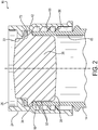
Fig 2 is a cross-sectional side view of the upper portion of the container system ofFig. 1 with tubing removed; -
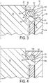
Fig 3 is a cross-sectional schematic side view of a portion of the container system ofFig 1 , where the spring element is shown in a first embodiment with one energized configuration; -
Fig 4 is a cross-sectional side view of a portion of the container system ofFig 1 , where the spring element is shown in another energized configuration; -
Fig 5 is a cross-sectional side view of a portion of the container system, showing a second embodiment of the spring element; -
Fig 6 a cross-sectional side view of a portion of the container system, showing a third embodiment of the spring element; -
Fig 7 is a cross-sectional side view of a portion of the container system, showing a fourth embodiment of the spring element; -
Fig 8 is a cross-sectional side view of a portion of the container system, showing a fifth embodiment of the spring element; and -
Fig 9 is a cross-sectional side view of a portion of the container system, showing a sixth embodiment of the spring element. - Referring now to
Figures 1 and2 , a container system is illustrated generally at 10, having acontainer body 14 with anelongated neck 15 with an annular mouth, indicated generally at 18, circumscribing a central axis, aresilient stopper 20 and acap 24 with acentral opening 26. The stopper has acircular body portion 30 closely received within the mouth and extending down into the neck, and can have one or more radially-projectingribs 32 circumscribing the outer surface of the stopper which compress in a sealing manner against the inner surface of the neck. The stopper has adistal end 33 which extends a short distance outwardly from the mouth and includes aradial flange 34 circumscribing the stopper. - As shown also in
Figure 3 , theflange 34 has an axially-outward facing annularflat surface 40 and an axially-inwardly facing annularflat surface 41.Flange 34 is located between thedistal end 42 of the mouth and thecap 18 when the container system is assembled, with the axially-inwardly facingsurface 41 in engagement with thedistal end 42 of the mouth. Thedistal end 33 of the stopper has a radially-outward facingannular surface 44, which together with the axially-outwardly facingsurface 40 of the flange, defines an outwardly-facing shoulder. - The
cap 24 has a cup-shaped configuration with anannular end wall 50 circumscribing acentral opening 52, and anannular side wall 54.Side wall 54 includes internal threads orflights 55 which cooperate with external threads orflights 56 on theneck 15 of the container to secure the cap onto the container. The end wall has an annular flat, axially-inwardly facingsurface 57, which together with a radially-inwardly facingsurface 60 of theside wall 54, defines an inwardly-facing shoulder in opposed relation to the outwardly facing shoulder of the stopper, with the axially-inwardly facingsurface 57 of the cap in opposed relation to the axially-outwardly facingsurface 40 of the flange of the stopper. An annular channel, indicated generally at 62, is defined between the surfaces of the stopper and cap. - An
annular spring element 70 is located in thechannel 62 between the cap and stopper, and according to a first embodiment, has a unitary, tear-drop shaped geometry in cross-section with a radially-outer, roundedbulbous body portion 72 smoothly tapering along aneck portion 74 to a curved, radially-inwardly projectinglip 76. - The spring element is preferably comprised of a resilient, high-performance thermoplastic polymer, such as polyketone or similar material such as polyether ether ketone, polyphenylsulfone or polycarbonate, which is capable of maintaining its pliancy and shape over a wide temperature range. An appropriate polyketone is available from Parker Hannifin GmbH, Bietigheim-Bissingen Germany, under the tradename Nobrox®. Again, other high-performance, chemically-resistant and biologically compatible material that maintains its pliancy and compression across wide temperature ranges may be appropriate depending on the particular application. The spring element is preferably formed (molded) in one unitary piece from a single material, but could be formed in multiple connected pieces of the same or different material as should be appreciated by those skilled in the art.
- The
spring element 70 is located in the channel such that the element has at least an axially inner surface or edge 78 of thebulbous body portion 72 sealingly engaged with the axially-outward facingsurface 40 of the flange, and an outer surface or edge 80 of thelip 76 sealingly engaged with the axially inwardly-facingsurface 57 of the cap. As shown inFigure 3 , the spring element has a configuration that defines two points of contact between the cap and the stopper; although as shown inFigure 4 , theelement 70 could be configured to have three points of contact with opposite sides oredges bulbous portion 72 sealingly engaging the axially inwardly-facingsurface 57 of thecap 50 and the axially-outwardly facingsurface 40 of the flange of the stopper, and thelip 76 separately sealingly engaging the axially inwardly-facingsurface 57 of the cap. - The stopper, cap, tubing and container can be formed of materials which are non-reactive to the liquids being stored and transported, and can withstand many of the typical operating conditions so that the contents of the container remain sterile and do not leak. Typical materials for the stopper include resilient plastics and elastomers such as polyether ketones, thermoplastic or silicone. Typical materials for the tubing include polycarbonate (e.g., silicone) or equivalent, while typical materials for the container include glass, plastic or other polymer such as polyethylene (e.g., Nalgene®), in a rigid (e.g., bottle-shaped) or flexible (e.g., a bag) form. The cap can be formed of a polymer such as plastic, elastomer, or other appropriate material. The stopper, cap, tubing and container can be formed using conventional techniques, such as molding and extruding.
- When the container system is assembled, the
stopper 20 is inserted into the mouth of the container with theflange 34 located against thedistal end 42 of the mouth. Thedistal end 33 of the stopper extends outwardly a short distance from the container body. Thespring element 70 can be located in the cap against the axially-inwardly facingsurface 57, and when the cap is screwed down onto the mouth of the container, the cap captures theflange 34 between the inneraxial surface 57 of the cap and thedistal end 42 of the mouth. Locating the spring element within the cap enables the cap and spring element to be preassembled as a closure assembly, and sterilized for use. Alternatively, the spring element can be initially located around distal end of the stopper, against the flange. In any event, when the cap is screwed onto the mouth of the container, the cap compresses thespring element 70 within the channel between the cap and the flange, which causes the spring element to compressively urge thestopper 20 inwardly against the mouth of the container, and hence urge theflange 34 against the distal end of the mouth. The compressive resiliency of the spring element maintains the seal between the flange of the stopper and the mouth of the container and also maintains a seal between the flange and the inside surface of the cap, even during low temperatures and cycling over a wide temperature range. - As indicated above, the
cap 24 includes acentral opening 26 in its end, which enables flexible tubing to be inserted into through-holes in the stopper to enable liquid to be introduced and withdrawn from the container. While shown as separate pieces, the tubes could likewise be formed in one piece with (unitarily) with the stopper. - During use, the liquid is introduced through a feed tube 90 (
Figure 1 ) under aseptic conditions into a cleaned and sterilized container, with avent tube 92 enabling air within the container to escape. The tubes are then closed, a protective over cap (not shown) is applied to the cap, and the container can be irradiated (if appropriate) and frozen for storage and transport. When it is desired to remove the contents of the container, the container is thawed, the tubes are re-opened, and the liquid is recovered. - Although not separately described, the container, cap, stopper and tubing can be sterilized, irradiated and otherwise cleaned before and during use to create an aseptic environment, as should be known to those skilled in the art. The stopper, tubing, container and cap can also be cleaned and reused if appropriate, but are typically disposed after a single use.
- According to other embodiments, the seal can have other asymmetrical shapes besides tear-drop shaped which provide a bias against the flange of the stopper, and hence maintain the flange in sealing relation against the distal end of the mouth of the container and a seal between the flange and the inside surface of the cap at low temperatures and when the container is cycled from low temperature to ambient.
- For example,
Figure 5 shows a second embodiment of thespring element 70 which has a V shape in cross-section. In such embodiment, the spring element has a pair of outwardly projectinglegs 73, with the distal ends engaging thecap 24, and the intersection of the legs engaging theflange 34 of thestopper 20. As with the first embodiment above, the spring element is located and compressed between the axially-inwardly facingsurface 57 of theouter wall 50 of thecap 24, and the axially-outwardly facingsurface 40 of theflange 34 of thestopper 20, when the cap is screwed onto the container. The spring element is shown having three points of contact - two at the distal ends of the legs of the V against the cap; and one at the intersection of the legs of the V against theflange 24. When thecap 24 is screwed down on thecontainer 14, the cap urges the spring element into compressed engagement with the flange of the stopper, which maintains the flange in sealing relation with the distal end of the mouth of the container as well as maintains a seal between the flange and the cap. -
Figure 6 shows a third embodiment of thespring element 70 having a conical configuration. This spring element is likewise positioned between thecap 24 andflange 34 of thestopper 20, but only has two opposite points of contact. -
Figure 7 shows a fourth embodiment of thespring element 70 having a helical configuration, with a single flight of the spring circumscribing the distal end of the stopper. This spring element is likewise positioned between thecap 24 andflange 34 of thestopper 20, with two points of contact. -
Figure 8 shows a fifth embodiment of thespring element 70 with a C-shaped configuration, with thelegs 74 of the spring element respectively engaging along two opposite side surfaces of the legs the axially-inwardly facingsurface 57 of thecap 24 and the axially-outwardly facingsurface 40 of theflange 34 of thestopper 20. -
Figure 9 shows a sixth embodiment of thespring element 70 having an S-shaped configuration also with two points of contact along the side surfaces 76 of the distal ends of the spring element against the axially-inwardly facingsurface 57 of thecap 24 and the axially-outwardly facingsurface 40 of theflange 34 of thestopper 20. - Again, spring elements having other asymmetrical configurations are possible as should be appreciated by those skilled in the art, where the spring element has a configuration that urges the flange of the stopper against the distal end of the mouth of the container and maintains a seal also between the flange and the cap even during low temperatures and cycling between low temperatures and ambient.
- Thus, as described above, a container system for liquids is provided which has an improved seal between the stopper and container which prevents leakage during low temperature storage and transport, and later use at ambient temperatures. The container system remains simple to manufacture and assemble, and relatively inexpensive to construct, as the stopper can continue to be made of low-cost, non-reactive resilient material, such as silicone or a similar material; while the spring element can be separately formed in different configurations and out of more expensive, high-performance materials, but overall, the system is capable of meeting the operational requirements of many biological and pharmaceutical applications.
- The principles, preferred embodiments and modes of operation of the present invention have been described in the foregoing specification. The invention which is intended to be protected herein should not, however, be construed as limited to the particular form described as it is to be regarded as illustrative rather than restrictive. Variations and changes may be made by those skilled in the art without departing from the scope of the invention as set forth in the appended claims.
Claims (14)
- A container system (10) for liquids, the container system (10) having i) a container body (14) with a mouth (18) circumscribing a central axis; ii) a resilient stopper (20) having a body portion (30) closely received within the mouth of the container and a distal end (33) projecting outwardly from the mouth, the distal end (33) having an annular flange (34) projecting radially outward from the distal end and having an axially-inwardly facing surface (41) and axially-outwardly facing surface (40), with the axially inwardly facing surface in sealed engaging relationship against a distal outer end (42) of the mouth; iii) a cap (24) secured over the mouth of the container body and enclosing the distal outer end of the stopper, the cap (24) including an axially-inwardly facing surface (57), characterised in that a channel (62) is defined between the axially-inwardly facing surface (57) of the cap and the axially-outward facing surface (40) of the flange of the stopper; and in that a spring element (70) is located in the channel (62) between the cap and stopper, the spring element (70) comprised of a resilient polymer and having a shaped geometry in cross-section defining at least two separate points of contact (76, 78) between the stopper and cap within the channel, wherein the spring element provides axial compression against the flange of the stopper to maintain the flange in sealing relationship with the distal end of the mouth of the container and maintains a seal between the stopper and cap.
- The container system as claimed in claim 1, wherein the spring element (70) has three separate points of contact (76, 78a, 78b) between the cap and the flange.
- The container system as claimed in any preceding claim, wherein the spring element has a rounded bulbous body portion (72) tapering to a curved, radially-inwardly projecting lip (76), and the spring element is located between the cap and stopper with the bulbous portion (72) having a surface (78) sealingly engaged with the axially outwardly-facing surface of the flange, and the lip (76) is sealingly engaged with the axially inwardly-facing surface of the cap.
- The container system as claimed in claim 3, wherein the bulbous portion has opposite surfaces (78, 80) sealingly engaged with and between the axially outwardly-facing surface of the flange and the axially inwardly-facing surface of the cap.
- The container system as claimed in claim 1, wherein the spring element has an asymmetric shape in cross-section sealing against the flange of the stopper and the cap.
- The container system as claimed in claim 5, wherein the spring element has a cone, helical, V, S or C shaped configuration in cross-section.
- The container system as claimed in any preceding claim, wherein the spring element has an annular, unitary configuration.
- The container system as claimed in any preceding claim, wherein the spring element is polyketone.
- The container system as claimed in any preceding claim, wherein the stopper is silicone.
- The container system as claimed in any preceding claim, wherein the distal end (33) of the stopper has a radially-outward facing surface (44), which together with the axially-outwardly facing surface (40) of the flange, defines an outwardly-facing shoulder, and the cap has a radially-inwardly facing surface (57) which together with the axially-inwardly facing surface (60) of the cap, defines an inwardly-facing shoulder in opposed relation to the outwardly facing shoulder of the stopper and defining the channel (62).
- The container system as claimed in any preceding claim, wherein the body portion (30) of the stopper includes one or more ribs (32) circumscribing an outer surface of the stopper.
- The container system as claimed in any preceding claim, wherein the cap has a cup-shaped body (50, 54) with a central opening (52).
- The container system as claimed in any preceding claim, wherein the cap and container body each include a threaded connection (55, 56).
- The container system as claimed in any preceding claim 1, wherein one or more tubes (90, 92) extend through the stopper (20) in fluid-tight relationship therewith to enable fluid to be introduced and/or removed from the container body (14).
Applications Claiming Priority (1)
| Application Number | Priority Date | Filing Date | Title |
|---|---|---|---|
| US201762463754P | 2017-02-27 | 2017-02-27 |
Publications (2)
| Publication Number | Publication Date |
|---|---|
| EP3366606A1 EP3366606A1 (en) | 2018-08-29 |
| EP3366606B1 true EP3366606B1 (en) | 2019-12-18 |
Family
ID=61283014
Family Applications (1)
| Application Number | Title | Priority Date | Filing Date |
|---|---|---|---|
| EP18158459.0A Active EP3366606B1 (en) | 2017-02-27 | 2018-02-23 | Container system |
Country Status (2)
| Country | Link |
|---|---|
| US (1) | US10611527B2 (en) |
| EP (1) | EP3366606B1 (en) |
Families Citing this family (1)
| Publication number | Priority date | Publication date | Assignee | Title |
|---|---|---|---|---|
| EP3962429A1 (en) * | 2019-05-03 | 2022-03-09 | Janssen Biotech, Inc. | Low temperature vials and vial assemblies |
Family Cites Families (9)
| Publication number | Priority date | Publication date | Assignee | Title |
|---|---|---|---|---|
| GB199957A (en) | 1922-07-10 | 1923-07-05 | David Browne | Closing means for bottles and other containers |
| US4534482A (en) * | 1984-05-23 | 1985-08-13 | Michel Bouche | Stoppering device for bottles |
| IT1308507B1 (en) * | 1999-01-29 | 2002-01-08 | Ferrari Group Srl | UNIVERSAL CAP FOR CLOSING UNCAPPED BOTTLES, IN PARTICULAR FOR SPARKLING OR WINE BOTTLES. |
| US6651834B2 (en) * | 2001-09-11 | 2003-11-25 | Hometec Limited | Bottle stopper with pressure indicator |
| EP1512572B1 (en) * | 2003-09-05 | 2009-12-30 | Toyoda Gosei Co., Ltd. | Cap device |
| US7819264B2 (en) | 2003-12-03 | 2010-10-26 | Rexam Closure Systems Inc. | Child-resistant closure, container and package |
| CN101034194A (en) * | 2006-03-10 | 2007-09-12 | 鸿富锦精密工业(深圳)有限公司 | Lens module group used in digital camera |
| US20090032488A1 (en) | 2007-07-30 | 2009-02-05 | Owens-Illinois Closure Inc. | Ceremonial plug closure and package |
| GB201515123D0 (en) * | 2015-08-26 | 2015-10-07 | Smiths Medical Int Ltd | Valves and tubes including valves |
-
2018
- 2018-02-14 US US15/896,279 patent/US10611527B2/en active Active
- 2018-02-23 EP EP18158459.0A patent/EP3366606B1/en active Active
Non-Patent Citations (1)
| Title |
|---|
| None * |
Also Published As
| Publication number | Publication date |
|---|---|
| EP3366606A1 (en) | 2018-08-29 |
| US20190055067A1 (en) | 2019-02-21 |
| US10611527B2 (en) | 2020-04-07 |
Similar Documents
| Publication | Publication Date | Title |
|---|---|---|
| US6662977B2 (en) | Modular valve assembly and system with airtight, leakproof and shockproof closure for engagement in the neck of a container | |
| US12162649B2 (en) | Containment and delivery systems for cryogenic storage | |
| CN102374346B (en) | High pressure fitting for hydrogen applications | |
| US6062436A (en) | Flexible vented self-sealing dispensing valve | |
| US9580214B2 (en) | Port closure system for use with a probe/feed/drain tool | |
| EP3687918B1 (en) | Sports bottle cap | |
| US6325253B1 (en) | Self-closing fluid dispensing closure | |
| US20090057259A1 (en) | Septa | |
| US20150084335A1 (en) | Pipe Coupling System and Methods of Use Thereof | |
| US4463862A (en) | Thermoplastic container | |
| JP2002528183A (en) | Cap and luer connector for fluid transfer device | |
| US20140319142A1 (en) | Membrane, and a neck including such membrane | |
| US20220023609A1 (en) | Dual ended disinfecting cap for stopcock valves | |
| EP2432705B1 (en) | Pour cap for fluid containers | |
| US20150027976A1 (en) | Bottle cap | |
| US10611527B2 (en) | Container system | |
| AU2009200949A1 (en) | Closure assembly | |
| US20080093396A1 (en) | Double bead sealing system for container closure | |
| US20170234446A1 (en) | Valve closures | |
| KR102373120B1 (en) | Cosmetic container assembly for easy separation and recycling | |
| US10293990B2 (en) | Closure system and container having a closure system | |
| KR101457447B1 (en) | Flexible pinch fitting for containers | |
| CN216509776U (en) | Fitting for a fluid containment system and containment system | |
| US20060076309A1 (en) | Mother's milk container closure and attachment assembly | |
| WO2012175412A1 (en) | Valve automatically opening on connection, and applications therefor |
Legal Events
| Date | Code | Title | Description |
|---|---|---|---|
| PUAI | Public reference made under article 153(3) epc to a published international application that has entered the european phase |
Free format text: ORIGINAL CODE: 0009012 |
|
| STAA | Information on the status of an ep patent application or granted ep patent |
Free format text: STATUS: THE APPLICATION HAS BEEN PUBLISHED |
|
| AK | Designated contracting states |
Kind code of ref document: A1 Designated state(s): AL AT BE BG CH CY CZ DE DK EE ES FI FR GB GR HR HU IE IS IT LI LT LU LV MC MK MT NL NO PL PT RO RS SE SI SK SM TR |
|
| AX | Request for extension of the european patent |
Extension state: BA ME |
|
| STAA | Information on the status of an ep patent application or granted ep patent |
Free format text: STATUS: REQUEST FOR EXAMINATION WAS MADE |
|
| 17P | Request for examination filed |
Effective date: 20190219 |
|
| RBV | Designated contracting states (corrected) |
Designated state(s): AL AT BE BG CH CY CZ DE DK EE ES FI FR GB GR HR HU IE IS IT LI LT LU LV MC MK MT NL NO PL PT RO RS SE SI SK SM TR |
|
| GRAP | Despatch of communication of intention to grant a patent |
Free format text: ORIGINAL CODE: EPIDOSNIGR1 |
|
| STAA | Information on the status of an ep patent application or granted ep patent |
Free format text: STATUS: GRANT OF PATENT IS INTENDED |
|
| INTG | Intention to grant announced |
Effective date: 20190716 |
|
| RAP1 | Party data changed (applicant data changed or rights of an application transferred) |
Owner name: PARKER HANNIFIN EMEA S.A.R.L. |
|
| GRAS | Grant fee paid |
Free format text: ORIGINAL CODE: EPIDOSNIGR3 |
|
| GRAA | (expected) grant |
Free format text: ORIGINAL CODE: 0009210 |
|
| STAA | Information on the status of an ep patent application or granted ep patent |
Free format text: STATUS: THE PATENT HAS BEEN GRANTED |
|
| AK | Designated contracting states |
Kind code of ref document: B1 Designated state(s): AL AT BE BG CH CY CZ DE DK EE ES FI FR GB GR HR HU IE IS IT LI LT LU LV MC MK MT NL NO PL PT RO RS SE SI SK SM TR |
|
| REG | Reference to a national code |
Ref country code: CH Ref legal event code: EP |
|
| REG | Reference to a national code |
Ref country code: DE Ref legal event code: R096 Ref document number: 602018001625 Country of ref document: DE |
|
| REG | Reference to a national code |
Ref country code: IE Ref legal event code: FG4D |
|
| REG | Reference to a national code |
Ref country code: AT Ref legal event code: REF Ref document number: 1214357 Country of ref document: AT Kind code of ref document: T Effective date: 20200115 |
|
| REG | Reference to a national code |
Ref country code: NL Ref legal event code: FP |
|
| PG25 | Lapsed in a contracting state [announced via postgrant information from national office to epo] |
Ref country code: LV Free format text: LAPSE BECAUSE OF FAILURE TO SUBMIT A TRANSLATION OF THE DESCRIPTION OR TO PAY THE FEE WITHIN THE PRESCRIBED TIME-LIMIT Effective date: 20191218 Ref country code: SE Free format text: LAPSE BECAUSE OF FAILURE TO SUBMIT A TRANSLATION OF THE DESCRIPTION OR TO PAY THE FEE WITHIN THE PRESCRIBED TIME-LIMIT Effective date: 20191218 Ref country code: LT Free format text: LAPSE BECAUSE OF FAILURE TO SUBMIT A TRANSLATION OF THE DESCRIPTION OR TO PAY THE FEE WITHIN THE PRESCRIBED TIME-LIMIT Effective date: 20191218 Ref country code: GR Free format text: LAPSE BECAUSE OF FAILURE TO SUBMIT A TRANSLATION OF THE DESCRIPTION OR TO PAY THE FEE WITHIN THE PRESCRIBED TIME-LIMIT Effective date: 20200319 Ref country code: NO Free format text: LAPSE BECAUSE OF FAILURE TO SUBMIT A TRANSLATION OF THE DESCRIPTION OR TO PAY THE FEE WITHIN THE PRESCRIBED TIME-LIMIT Effective date: 20200318 Ref country code: BG Free format text: LAPSE BECAUSE OF FAILURE TO SUBMIT A TRANSLATION OF THE DESCRIPTION OR TO PAY THE FEE WITHIN THE PRESCRIBED TIME-LIMIT Effective date: 20200318 Ref country code: FI Free format text: LAPSE BECAUSE OF FAILURE TO SUBMIT A TRANSLATION OF THE DESCRIPTION OR TO PAY THE FEE WITHIN THE PRESCRIBED TIME-LIMIT Effective date: 20191218 |
|
| REG | Reference to a national code |
Ref country code: LT Ref legal event code: MG4D |
|
| PG25 | Lapsed in a contracting state [announced via postgrant information from national office to epo] |
Ref country code: HR Free format text: LAPSE BECAUSE OF FAILURE TO SUBMIT A TRANSLATION OF THE DESCRIPTION OR TO PAY THE FEE WITHIN THE PRESCRIBED TIME-LIMIT Effective date: 20191218 Ref country code: RS Free format text: LAPSE BECAUSE OF FAILURE TO SUBMIT A TRANSLATION OF THE DESCRIPTION OR TO PAY THE FEE WITHIN THE PRESCRIBED TIME-LIMIT Effective date: 20191218 |
|
| PG25 | Lapsed in a contracting state [announced via postgrant information from national office to epo] |
Ref country code: AL Free format text: LAPSE BECAUSE OF FAILURE TO SUBMIT A TRANSLATION OF THE DESCRIPTION OR TO PAY THE FEE WITHIN THE PRESCRIBED TIME-LIMIT Effective date: 20191218 |
|
| PG25 | Lapsed in a contracting state [announced via postgrant information from national office to epo] |
Ref country code: RO Free format text: LAPSE BECAUSE OF FAILURE TO SUBMIT A TRANSLATION OF THE DESCRIPTION OR TO PAY THE FEE WITHIN THE PRESCRIBED TIME-LIMIT Effective date: 20191218 Ref country code: CZ Free format text: LAPSE BECAUSE OF FAILURE TO SUBMIT A TRANSLATION OF THE DESCRIPTION OR TO PAY THE FEE WITHIN THE PRESCRIBED TIME-LIMIT Effective date: 20191218 Ref country code: PT Free format text: LAPSE BECAUSE OF FAILURE TO SUBMIT A TRANSLATION OF THE DESCRIPTION OR TO PAY THE FEE WITHIN THE PRESCRIBED TIME-LIMIT Effective date: 20200513 Ref country code: EE Free format text: LAPSE BECAUSE OF FAILURE TO SUBMIT A TRANSLATION OF THE DESCRIPTION OR TO PAY THE FEE WITHIN THE PRESCRIBED TIME-LIMIT Effective date: 20191218 |
|
| PG25 | Lapsed in a contracting state [announced via postgrant information from national office to epo] |
Ref country code: SK Free format text: LAPSE BECAUSE OF FAILURE TO SUBMIT A TRANSLATION OF THE DESCRIPTION OR TO PAY THE FEE WITHIN THE PRESCRIBED TIME-LIMIT Effective date: 20191218 Ref country code: IS Free format text: LAPSE BECAUSE OF FAILURE TO SUBMIT A TRANSLATION OF THE DESCRIPTION OR TO PAY THE FEE WITHIN THE PRESCRIBED TIME-LIMIT Effective date: 20200418 Ref country code: SM Free format text: LAPSE BECAUSE OF FAILURE TO SUBMIT A TRANSLATION OF THE DESCRIPTION OR TO PAY THE FEE WITHIN THE PRESCRIBED TIME-LIMIT Effective date: 20191218 |
|
| REG | Reference to a national code |
Ref country code: DE Ref legal event code: R097 Ref document number: 602018001625 Country of ref document: DE |
|
| REG | Reference to a national code |
Ref country code: AT Ref legal event code: MK05 Ref document number: 1214357 Country of ref document: AT Kind code of ref document: T Effective date: 20191218 |
|
| PLBE | No opposition filed within time limit |
Free format text: ORIGINAL CODE: 0009261 |
|
| STAA | Information on the status of an ep patent application or granted ep patent |
Free format text: STATUS: NO OPPOSITION FILED WITHIN TIME LIMIT |
|
| REG | Reference to a national code |
Ref country code: BE Ref legal event code: MM Effective date: 20200229 |
|
| PG25 | Lapsed in a contracting state [announced via postgrant information from national office to epo] |
Ref country code: ES Free format text: LAPSE BECAUSE OF FAILURE TO SUBMIT A TRANSLATION OF THE DESCRIPTION OR TO PAY THE FEE WITHIN THE PRESCRIBED TIME-LIMIT Effective date: 20191218 Ref country code: LU Free format text: LAPSE BECAUSE OF NON-PAYMENT OF DUE FEES Effective date: 20200223 Ref country code: MC Free format text: LAPSE BECAUSE OF FAILURE TO SUBMIT A TRANSLATION OF THE DESCRIPTION OR TO PAY THE FEE WITHIN THE PRESCRIBED TIME-LIMIT Effective date: 20191218 Ref country code: DK Free format text: LAPSE BECAUSE OF FAILURE TO SUBMIT A TRANSLATION OF THE DESCRIPTION OR TO PAY THE FEE WITHIN THE PRESCRIBED TIME-LIMIT Effective date: 20191218 |
|
| 26N | No opposition filed |
Effective date: 20200921 |
|
| PG25 | Lapsed in a contracting state [announced via postgrant information from national office to epo] |
Ref country code: SI Free format text: LAPSE BECAUSE OF FAILURE TO SUBMIT A TRANSLATION OF THE DESCRIPTION OR TO PAY THE FEE WITHIN THE PRESCRIBED TIME-LIMIT Effective date: 20191218 Ref country code: AT Free format text: LAPSE BECAUSE OF FAILURE TO SUBMIT A TRANSLATION OF THE DESCRIPTION OR TO PAY THE FEE WITHIN THE PRESCRIBED TIME-LIMIT Effective date: 20191218 |
|
| PG25 | Lapsed in a contracting state [announced via postgrant information from national office to epo] |
Ref country code: FR Free format text: LAPSE BECAUSE OF NON-PAYMENT OF DUE FEES Effective date: 20200229 Ref country code: IT Free format text: LAPSE BECAUSE OF FAILURE TO SUBMIT A TRANSLATION OF THE DESCRIPTION OR TO PAY THE FEE WITHIN THE PRESCRIBED TIME-LIMIT Effective date: 20191218 |
|
| PG25 | Lapsed in a contracting state [announced via postgrant information from national office to epo] |
Ref country code: BE Free format text: LAPSE BECAUSE OF NON-PAYMENT OF DUE FEES Effective date: 20200229 Ref country code: PL Free format text: LAPSE BECAUSE OF FAILURE TO SUBMIT A TRANSLATION OF THE DESCRIPTION OR TO PAY THE FEE WITHIN THE PRESCRIBED TIME-LIMIT Effective date: 20191218 |
|
| PG25 | Lapsed in a contracting state [announced via postgrant information from national office to epo] |
Ref country code: TR Free format text: LAPSE BECAUSE OF FAILURE TO SUBMIT A TRANSLATION OF THE DESCRIPTION OR TO PAY THE FEE WITHIN THE PRESCRIBED TIME-LIMIT Effective date: 20191218 Ref country code: MT Free format text: LAPSE BECAUSE OF FAILURE TO SUBMIT A TRANSLATION OF THE DESCRIPTION OR TO PAY THE FEE WITHIN THE PRESCRIBED TIME-LIMIT Effective date: 20191218 Ref country code: CY Free format text: LAPSE BECAUSE OF FAILURE TO SUBMIT A TRANSLATION OF THE DESCRIPTION OR TO PAY THE FEE WITHIN THE PRESCRIBED TIME-LIMIT Effective date: 20191218 |
|
| PG25 | Lapsed in a contracting state [announced via postgrant information from national office to epo] |
Ref country code: MK Free format text: LAPSE BECAUSE OF FAILURE TO SUBMIT A TRANSLATION OF THE DESCRIPTION OR TO PAY THE FEE WITHIN THE PRESCRIBED TIME-LIMIT Effective date: 20191218 |
|
| P01 | Opt-out of the competence of the unified patent court (upc) registered |
Effective date: 20230524 |
|
| REG | Reference to a national code |
Ref country code: DE Ref legal event code: R082 Ref document number: 602018001625 Country of ref document: DE Representative=s name: DIPAS PATENTANWALTS GMBH, DE |
|
| REG | Reference to a national code |
Ref country code: CH Ref legal event code: U11 Free format text: ST27 STATUS EVENT CODE: U-0-0-U10-U11 (AS PROVIDED BY THE NATIONAL OFFICE) Effective date: 20260301 |
|
| PGFP | Annual fee paid to national office [announced via postgrant information from national office to epo] |
Ref country code: NL Payment date: 20260226 Year of fee payment: 9 |
|
| PGFP | Annual fee paid to national office [announced via postgrant information from national office to epo] |
Ref country code: GB Payment date: 20260227 Year of fee payment: 9 |
|
| PGFP | Annual fee paid to national office [announced via postgrant information from national office to epo] |
Ref country code: DE Payment date: 20260227 Year of fee payment: 9 Ref country code: IE Payment date: 20260227 Year of fee payment: 9 |
|
| PGFP | Annual fee paid to national office [announced via postgrant information from national office to epo] |
Ref country code: CH Payment date: 20260301 Year of fee payment: 9 |