EP3366568A1 - Double-shell tank for ship, and ship - Google Patents
Double-shell tank for ship, and ship Download PDFInfo
- Publication number
- EP3366568A1 EP3366568A1 EP16857509.0A EP16857509A EP3366568A1 EP 3366568 A1 EP3366568 A1 EP 3366568A1 EP 16857509 A EP16857509 A EP 16857509A EP 3366568 A1 EP3366568 A1 EP 3366568A1
- Authority
- EP
- European Patent Office
- Prior art keywords
- inner shell
- support member
- dome
- support
- shell
- Prior art date
- Legal status (The legal status is an assumption and is not a legal conclusion. Google has not performed a legal analysis and makes no representation as to the accuracy of the status listed.)
- Granted
Links
Images



Classifications
-
- B—PERFORMING OPERATIONS; TRANSPORTING
- B63—SHIPS OR OTHER WATERBORNE VESSELS; RELATED EQUIPMENT
- B63B—SHIPS OR OTHER WATERBORNE VESSELS; EQUIPMENT FOR SHIPPING
- B63B25/00—Load-accommodating arrangements, e.g. stowing, trimming; Vessels characterised thereby
- B63B25/02—Load-accommodating arrangements, e.g. stowing, trimming; Vessels characterised thereby for bulk goods
- B63B25/08—Load-accommodating arrangements, e.g. stowing, trimming; Vessels characterised thereby for bulk goods fluid
- B63B25/12—Load-accommodating arrangements, e.g. stowing, trimming; Vessels characterised thereby for bulk goods fluid closed
- B63B25/16—Load-accommodating arrangements, e.g. stowing, trimming; Vessels characterised thereby for bulk goods fluid closed heat-insulated
-
- F—MECHANICAL ENGINEERING; LIGHTING; HEATING; WEAPONS; BLASTING
- F17—STORING OR DISTRIBUTING GASES OR LIQUIDS
- F17C—VESSELS FOR CONTAINING OR STORING COMPRESSED, LIQUEFIED OR SOLIDIFIED GASES; FIXED-CAPACITY GAS-HOLDERS; FILLING VESSELS WITH, OR DISCHARGING FROM VESSELS, COMPRESSED, LIQUEFIED, OR SOLIDIFIED GASES
- F17C13/00—Details of vessels or of the filling or discharging of vessels
- F17C13/08—Mounting arrangements for vessels
- F17C13/082—Mounting arrangements for vessels for large sea-borne storage vessels
-
- F—MECHANICAL ENGINEERING; LIGHTING; HEATING; WEAPONS; BLASTING
- F17—STORING OR DISTRIBUTING GASES OR LIQUIDS
- F17C—VESSELS FOR CONTAINING OR STORING COMPRESSED, LIQUEFIED OR SOLIDIFIED GASES; FIXED-CAPACITY GAS-HOLDERS; FILLING VESSELS WITH, OR DISCHARGING FROM VESSELS, COMPRESSED, LIQUEFIED, OR SOLIDIFIED GASES
- F17C3/00—Vessels not under pressure
-
- F—MECHANICAL ENGINEERING; LIGHTING; HEATING; WEAPONS; BLASTING
- F17—STORING OR DISTRIBUTING GASES OR LIQUIDS
- F17C—VESSELS FOR CONTAINING OR STORING COMPRESSED, LIQUEFIED OR SOLIDIFIED GASES; FIXED-CAPACITY GAS-HOLDERS; FILLING VESSELS WITH, OR DISCHARGING FROM VESSELS, COMPRESSED, LIQUEFIED, OR SOLIDIFIED GASES
- F17C3/00—Vessels not under pressure
- F17C3/02—Vessels not under pressure with provision for thermal insulation
- F17C3/025—Bulk storage in barges or on ships
-
- F—MECHANICAL ENGINEERING; LIGHTING; HEATING; WEAPONS; BLASTING
- F17—STORING OR DISTRIBUTING GASES OR LIQUIDS
- F17C—VESSELS FOR CONTAINING OR STORING COMPRESSED, LIQUEFIED OR SOLIDIFIED GASES; FIXED-CAPACITY GAS-HOLDERS; FILLING VESSELS WITH, OR DISCHARGING FROM VESSELS, COMPRESSED, LIQUEFIED, OR SOLIDIFIED GASES
- F17C3/00—Vessels not under pressure
- F17C3/02—Vessels not under pressure with provision for thermal insulation
- F17C3/08—Vessels not under pressure with provision for thermal insulation by vacuum spaces, e.g. Dewar flask
-
- B—PERFORMING OPERATIONS; TRANSPORTING
- B63—SHIPS OR OTHER WATERBORNE VESSELS; RELATED EQUIPMENT
- B63B—SHIPS OR OTHER WATERBORNE VESSELS; EQUIPMENT FOR SHIPPING
- B63B25/00—Load-accommodating arrangements, e.g. stowing, trimming; Vessels characterised thereby
- B63B25/02—Load-accommodating arrangements, e.g. stowing, trimming; Vessels characterised thereby for bulk goods
- B63B25/08—Load-accommodating arrangements, e.g. stowing, trimming; Vessels characterised thereby for bulk goods fluid
- B63B2025/087—Load-accommodating arrangements, e.g. stowing, trimming; Vessels characterised thereby for bulk goods fluid comprising self-contained tanks installed in the ship structure as separate units
-
- B—PERFORMING OPERATIONS; TRANSPORTING
- B63—SHIPS OR OTHER WATERBORNE VESSELS; RELATED EQUIPMENT
- B63B—SHIPS OR OTHER WATERBORNE VESSELS; EQUIPMENT FOR SHIPPING
- B63B2231/00—Material used for some parts or elements, or for particular purposes
- B63B2231/40—Synthetic materials
- B63B2231/52—Fibre reinforced plastics materials
-
- F—MECHANICAL ENGINEERING; LIGHTING; HEATING; WEAPONS; BLASTING
- F17—STORING OR DISTRIBUTING GASES OR LIQUIDS
- F17C—VESSELS FOR CONTAINING OR STORING COMPRESSED, LIQUEFIED OR SOLIDIFIED GASES; FIXED-CAPACITY GAS-HOLDERS; FILLING VESSELS WITH, OR DISCHARGING FROM VESSELS, COMPRESSED, LIQUEFIED, OR SOLIDIFIED GASES
- F17C2201/00—Vessel construction, in particular geometry, arrangement or size
- F17C2201/01—Shape
- F17C2201/0104—Shape cylindrical
- F17C2201/0109—Shape cylindrical with exteriorly curved end-piece
-
- F—MECHANICAL ENGINEERING; LIGHTING; HEATING; WEAPONS; BLASTING
- F17—STORING OR DISTRIBUTING GASES OR LIQUIDS
- F17C—VESSELS FOR CONTAINING OR STORING COMPRESSED, LIQUEFIED OR SOLIDIFIED GASES; FIXED-CAPACITY GAS-HOLDERS; FILLING VESSELS WITH, OR DISCHARGING FROM VESSELS, COMPRESSED, LIQUEFIED, OR SOLIDIFIED GASES
- F17C2201/00—Vessel construction, in particular geometry, arrangement or size
- F17C2201/03—Orientation
- F17C2201/035—Orientation with substantially horizontal main axis
-
- F—MECHANICAL ENGINEERING; LIGHTING; HEATING; WEAPONS; BLASTING
- F17—STORING OR DISTRIBUTING GASES OR LIQUIDS
- F17C—VESSELS FOR CONTAINING OR STORING COMPRESSED, LIQUEFIED OR SOLIDIFIED GASES; FIXED-CAPACITY GAS-HOLDERS; FILLING VESSELS WITH, OR DISCHARGING FROM VESSELS, COMPRESSED, LIQUEFIED, OR SOLIDIFIED GASES
- F17C2201/00—Vessel construction, in particular geometry, arrangement or size
- F17C2201/05—Size
- F17C2201/054—Size medium (>1 m3)
-
- F—MECHANICAL ENGINEERING; LIGHTING; HEATING; WEAPONS; BLASTING
- F17—STORING OR DISTRIBUTING GASES OR LIQUIDS
- F17C—VESSELS FOR CONTAINING OR STORING COMPRESSED, LIQUEFIED OR SOLIDIFIED GASES; FIXED-CAPACITY GAS-HOLDERS; FILLING VESSELS WITH, OR DISCHARGING FROM VESSELS, COMPRESSED, LIQUEFIED, OR SOLIDIFIED GASES
- F17C2203/00—Vessel construction, in particular walls or details thereof
- F17C2203/01—Reinforcing or suspension means
- F17C2203/014—Suspension means
- F17C2203/015—Bars
-
- F—MECHANICAL ENGINEERING; LIGHTING; HEATING; WEAPONS; BLASTING
- F17—STORING OR DISTRIBUTING GASES OR LIQUIDS
- F17C—VESSELS FOR CONTAINING OR STORING COMPRESSED, LIQUEFIED OR SOLIDIFIED GASES; FIXED-CAPACITY GAS-HOLDERS; FILLING VESSELS WITH, OR DISCHARGING FROM VESSELS, COMPRESSED, LIQUEFIED, OR SOLIDIFIED GASES
- F17C2203/00—Vessel construction, in particular walls or details thereof
- F17C2203/03—Thermal insulations
- F17C2203/0375—Thermal insulations by gas
- F17C2203/0379—Inert
-
- F—MECHANICAL ENGINEERING; LIGHTING; HEATING; WEAPONS; BLASTING
- F17—STORING OR DISTRIBUTING GASES OR LIQUIDS
- F17C—VESSELS FOR CONTAINING OR STORING COMPRESSED, LIQUEFIED OR SOLIDIFIED GASES; FIXED-CAPACITY GAS-HOLDERS; FILLING VESSELS WITH, OR DISCHARGING FROM VESSELS, COMPRESSED, LIQUEFIED, OR SOLIDIFIED GASES
- F17C2203/00—Vessel construction, in particular walls or details thereof
- F17C2203/03—Thermal insulations
- F17C2203/0391—Thermal insulations by vacuum
-
- F—MECHANICAL ENGINEERING; LIGHTING; HEATING; WEAPONS; BLASTING
- F17—STORING OR DISTRIBUTING GASES OR LIQUIDS
- F17C—VESSELS FOR CONTAINING OR STORING COMPRESSED, LIQUEFIED OR SOLIDIFIED GASES; FIXED-CAPACITY GAS-HOLDERS; FILLING VESSELS WITH, OR DISCHARGING FROM VESSELS, COMPRESSED, LIQUEFIED, OR SOLIDIFIED GASES
- F17C2203/00—Vessel construction, in particular walls or details thereof
- F17C2203/06—Materials for walls or layers thereof; Properties or structures of walls or their materials
- F17C2203/0602—Wall structures; Special features thereof
- F17C2203/0612—Wall structures
- F17C2203/0626—Multiple walls
- F17C2203/0629—Two walls
-
- F—MECHANICAL ENGINEERING; LIGHTING; HEATING; WEAPONS; BLASTING
- F17—STORING OR DISTRIBUTING GASES OR LIQUIDS
- F17C—VESSELS FOR CONTAINING OR STORING COMPRESSED, LIQUEFIED OR SOLIDIFIED GASES; FIXED-CAPACITY GAS-HOLDERS; FILLING VESSELS WITH, OR DISCHARGING FROM VESSELS, COMPRESSED, LIQUEFIED, OR SOLIDIFIED GASES
- F17C2205/00—Vessel construction, in particular mounting arrangements, attachments or identifications means
- F17C2205/01—Mounting arrangements
- F17C2205/0123—Mounting arrangements characterised by number of vessels
- F17C2205/013—Two or more vessels
- F17C2205/0149—Vessel mounted inside another one
-
- F—MECHANICAL ENGINEERING; LIGHTING; HEATING; WEAPONS; BLASTING
- F17—STORING OR DISTRIBUTING GASES OR LIQUIDS
- F17C—VESSELS FOR CONTAINING OR STORING COMPRESSED, LIQUEFIED OR SOLIDIFIED GASES; FIXED-CAPACITY GAS-HOLDERS; FILLING VESSELS WITH, OR DISCHARGING FROM VESSELS, COMPRESSED, LIQUEFIED, OR SOLIDIFIED GASES
- F17C2205/00—Vessel construction, in particular mounting arrangements, attachments or identifications means
- F17C2205/01—Mounting arrangements
- F17C2205/0153—Details of mounting arrangements
- F17C2205/018—Supporting feet
-
- F—MECHANICAL ENGINEERING; LIGHTING; HEATING; WEAPONS; BLASTING
- F17—STORING OR DISTRIBUTING GASES OR LIQUIDS
- F17C—VESSELS FOR CONTAINING OR STORING COMPRESSED, LIQUEFIED OR SOLIDIFIED GASES; FIXED-CAPACITY GAS-HOLDERS; FILLING VESSELS WITH, OR DISCHARGING FROM VESSELS, COMPRESSED, LIQUEFIED, OR SOLIDIFIED GASES
- F17C2205/00—Vessel construction, in particular mounting arrangements, attachments or identifications means
- F17C2205/03—Fluid connections, filters, valves, closure means or other attachments
- F17C2205/0302—Fittings, valves, filters, or components in connection with the gas storage device
- F17C2205/0308—Protective caps
-
- F—MECHANICAL ENGINEERING; LIGHTING; HEATING; WEAPONS; BLASTING
- F17—STORING OR DISTRIBUTING GASES OR LIQUIDS
- F17C—VESSELS FOR CONTAINING OR STORING COMPRESSED, LIQUEFIED OR SOLIDIFIED GASES; FIXED-CAPACITY GAS-HOLDERS; FILLING VESSELS WITH, OR DISCHARGING FROM VESSELS, COMPRESSED, LIQUEFIED, OR SOLIDIFIED GASES
- F17C2221/00—Handled fluid, in particular type of fluid
- F17C2221/01—Pure fluids
- F17C2221/012—Hydrogen
-
- F—MECHANICAL ENGINEERING; LIGHTING; HEATING; WEAPONS; BLASTING
- F17—STORING OR DISTRIBUTING GASES OR LIQUIDS
- F17C—VESSELS FOR CONTAINING OR STORING COMPRESSED, LIQUEFIED OR SOLIDIFIED GASES; FIXED-CAPACITY GAS-HOLDERS; FILLING VESSELS WITH, OR DISCHARGING FROM VESSELS, COMPRESSED, LIQUEFIED, OR SOLIDIFIED GASES
- F17C2221/00—Handled fluid, in particular type of fluid
- F17C2221/01—Pure fluids
- F17C2221/016—Noble gases (Ar, Kr, Xe)
- F17C2221/017—Helium
-
- F—MECHANICAL ENGINEERING; LIGHTING; HEATING; WEAPONS; BLASTING
- F17—STORING OR DISTRIBUTING GASES OR LIQUIDS
- F17C—VESSELS FOR CONTAINING OR STORING COMPRESSED, LIQUEFIED OR SOLIDIFIED GASES; FIXED-CAPACITY GAS-HOLDERS; FILLING VESSELS WITH, OR DISCHARGING FROM VESSELS, COMPRESSED, LIQUEFIED, OR SOLIDIFIED GASES
- F17C2221/00—Handled fluid, in particular type of fluid
- F17C2221/03—Mixtures
- F17C2221/032—Hydrocarbons
- F17C2221/033—Methane, e.g. natural gas, CNG, LNG, GNL, GNC, PLNG
-
- F—MECHANICAL ENGINEERING; LIGHTING; HEATING; WEAPONS; BLASTING
- F17—STORING OR DISTRIBUTING GASES OR LIQUIDS
- F17C—VESSELS FOR CONTAINING OR STORING COMPRESSED, LIQUEFIED OR SOLIDIFIED GASES; FIXED-CAPACITY GAS-HOLDERS; FILLING VESSELS WITH, OR DISCHARGING FROM VESSELS, COMPRESSED, LIQUEFIED, OR SOLIDIFIED GASES
- F17C2221/00—Handled fluid, in particular type of fluid
- F17C2221/03—Mixtures
- F17C2221/032—Hydrocarbons
- F17C2221/035—Propane butane, e.g. LPG, GPL
-
- F—MECHANICAL ENGINEERING; LIGHTING; HEATING; WEAPONS; BLASTING
- F17—STORING OR DISTRIBUTING GASES OR LIQUIDS
- F17C—VESSELS FOR CONTAINING OR STORING COMPRESSED, LIQUEFIED OR SOLIDIFIED GASES; FIXED-CAPACITY GAS-HOLDERS; FILLING VESSELS WITH, OR DISCHARGING FROM VESSELS, COMPRESSED, LIQUEFIED, OR SOLIDIFIED GASES
- F17C2223/00—Handled fluid before transfer, i.e. state of fluid when stored in the vessel or before transfer from the vessel
- F17C2223/01—Handled fluid before transfer, i.e. state of fluid when stored in the vessel or before transfer from the vessel characterised by the phase
- F17C2223/0146—Two-phase
- F17C2223/0153—Liquefied gas, e.g. LPG, GPL
- F17C2223/0161—Liquefied gas, e.g. LPG, GPL cryogenic, e.g. LNG, GNL, PLNG
-
- F—MECHANICAL ENGINEERING; LIGHTING; HEATING; WEAPONS; BLASTING
- F17—STORING OR DISTRIBUTING GASES OR LIQUIDS
- F17C—VESSELS FOR CONTAINING OR STORING COMPRESSED, LIQUEFIED OR SOLIDIFIED GASES; FIXED-CAPACITY GAS-HOLDERS; FILLING VESSELS WITH, OR DISCHARGING FROM VESSELS, COMPRESSED, LIQUEFIED, OR SOLIDIFIED GASES
- F17C2223/00—Handled fluid before transfer, i.e. state of fluid when stored in the vessel or before transfer from the vessel
- F17C2223/03—Handled fluid before transfer, i.e. state of fluid when stored in the vessel or before transfer from the vessel characterised by the pressure level
- F17C2223/033—Small pressure, e.g. for liquefied gas
-
- F—MECHANICAL ENGINEERING; LIGHTING; HEATING; WEAPONS; BLASTING
- F17—STORING OR DISTRIBUTING GASES OR LIQUIDS
- F17C—VESSELS FOR CONTAINING OR STORING COMPRESSED, LIQUEFIED OR SOLIDIFIED GASES; FIXED-CAPACITY GAS-HOLDERS; FILLING VESSELS WITH, OR DISCHARGING FROM VESSELS, COMPRESSED, LIQUEFIED, OR SOLIDIFIED GASES
- F17C2270/00—Applications
- F17C2270/01—Applications for fluid transport or storage
- F17C2270/0102—Applications for fluid transport or storage on or in the water
- F17C2270/0105—Ships
Definitions
- the present invention relates to a double-shell ship tank mounted on a ship and a ship including the double-shell ship tank.
- a double-shell tank for a liquefied gas is mounted on a ship, such as a liquefied gas carrier.
- a thermal insulating layer e.g., a vacuum thermal insulating layer
- Patent Literature 1 for example.
- the inner shell includes an inner shell main part storing a liquefied gas and an inner shell dome protruding upward from the inner shell main part
- the outer shell includes an outer shell main part surrounding the inner shell main part and an outer shell dome surrounding the inner shell dome.
- the inner shell dome is intended for putting pipes penetrating the inner shell into one place. These pipes are disposed such that they penetrate the inner shell dome and the outer shell dome.
- an object of the present invention is to provide: a double-shell ship tank capable of restricting the dome-to-dome relative position while allowing the thermal contraction of the inner shell dome; and a ship including the double-shell ship tank.
- a double-shell ship tank includes: an inner shell including an inner shell main part storing a liquefied gas and an inner shell dome protruding upward from the inner shell main part; an outer shell including an outer shell main part surrounding the inner shell main part and an outer shell dome surrounding the inner shell dome; and at least three support mechanisms disposed around the inner shell dome between the inner shell and the outer shell.
- Each of the support mechanisms includes: a first support member fixed to one of the inner shell and the outer shell, the first support member including a first supporting surface parallel to a reference plane that includes a central axis of the inner shell dome; a second support member fixed to the other one of the inner shell and the outer shell, the second support member including a second supporting surface facing the first supporting surface; and an insulating member interposed between the first supporting surface and the second supporting surface, the insulating member being fixed to the second supporting surface and sliding along the first supporting surface.
- One of the first support member and the second support member, the one support member being fixed to the inner shell is positioned on the reference plane.
- the at least three support mechanisms are disposed around the inner shell dome, and the insulating member included in each support mechanism is movable in a direction parallel to the reference plane that includes the central axis of the inner shell dome. This makes it possible to restrict the dome-to-dome relative position while allowing thermal contraction of the inner shell dome in the axial direction and the radial direction.
- the first support member may be a plate whose one main surface is the first supporting surface
- the second support member may be a plate whose one main surface is the second supporting surface. According to this configuration, the first support member and the second support member can be fabricated at low cost.
- the first support member may be fixed to the outer shell dome or the outer shell main part, and the second support member may be fixed to the inner shell dome or the inner shell main part. According to this configuration, the temperature of the first supporting surface is kept at substantially ordinary temperatures. Therefore, the sliding performance between the insulating member and the first supporting surface can be designed under ordinary temperature conditions.
- the insulating member may be tubular and may extend in a direction orthogonal to the reference plane. According to this configuration, entry of heat from the outside of the outer shell into the inner shell via the insulating member can be suppressed.
- Each of the support mechanisms may include a first holding member that holds one end of the tubular insulating member and a second holding member that holds another end of the tubular insulating member.
- the tubular insulating member may be in contact with the first supporting surface via the first holding member, and may be fixed to the second supporting surface via the second holding member. According to this configuration, one end of the simple-shaped tubular insulating member can be readily fixed to the second supporting surface by using the second holding member.
- the first holding member which holds the other end of the tubular insulating member, can be contacted with the first supporting surface over a large area. This makes it possible to allow the tubular insulating member to make smooth sliding movement together with the first holding member.
- a lubricating liner may be sandwiched between the first holding member and the first supporting surface. According to this configuration, favorable sliding ability can be obtained with a simple configuration.
- the insulating member may be made of glass fiber reinforced plastic. According to this configuration, the entry of heat via the insulating member can be further suppressed.
- the second support member may be a plate whose one main surface and another main surface each serve as the second supporting surface.
- Each of the support mechanisms may include a pair of the first support members disposed at both sides of the second support member. According to this configuration, each support mechanism alone can restrict the inner shell dome in the circumferential direction.
- Each of the support mechanisms may include one first support member and one second support member.
- a positional relationship between the one first support member and the one second support member may be reversed between adjacent support mechanisms among the at least three support mechanisms. This configuration makes it possible to simplify the structure of each support mechanism while restricting the dome-to-dome relative position and restricting the inner shell dome in the circumferential direction, and facilitate position adjustment between the support mechanisms.
- Each of the support mechanisms may include one first support member and one second support member.
- the at least three support mechanisms may be four or more support mechanisms, and in each one of at least four pairs of the support mechanisms that are adjacent to each other, a positional relationship between the one first support member and the one second support member may be reversed between the adjacent support mechanisms. This configuration also makes it possible to simplify the structure of each support mechanism while restricting the dome-to-dome relative position and restricting the inner shell dome in the circumferential direction.
- a space between the inner shell and the outer shell may be a vacuum space. According to this configuration, the liquefied gas can be kept at low temperatures for a long period of time.
- the inner shell main part may be cylindrical and may extend in a horizontal direction.
- the at least three support mechanisms may be four support mechanisms that are disposed between the inner shell dome and the outer shell dome, each support mechanism being disposed at a position that is away from the central axis of the inner shell dome in an angular direction of 45 degrees relative to an axial direction of the inner shell main part. According to this configuration, the distances from the inner shell main part to all the support mechanisms can be made equal to each other. Consequently, loads exerted on all the support mechanisms can be made uniform.
- a ship according to the present invention includes the above-described double-shell ship tank.
- the present invention makes it possible to restrict the dome-to-dome relative position while allowing thermal contraction of the inner shell dome.
- Fig. 1 shows a double-shell ship tank 2A mounted on a ship 1, such as a liquefied gas carrier, according to Embodiment 1 of the present invention.
- the double-shell tank 2A includes an inner shell 3 and an outer shell 4.
- the outer shell 4 surrounds a space 20 formed around the inner shell 3.
- the space 20 between the inner shell 3 and the outer shell 4 is a vacuum space.
- the space 20 between the inner shell 3 and the outer shell 4 may be filled with a gas having low thermal conductivity, such as argon gas.
- the inner shell 3 includes an inner shell main part 31 storing a liquefied gas and an inner shell dome 32 protruding upward from the inner shell main part 31.
- the axial direction of the inner shell dome 32 is parallel to the vertical direction.
- the axial direction of the inner shell dome 32 may be slightly inclined relative to the vertical direction.
- the inner shell dome 32 is provided with a manhole 30 intended for inspection of the inside of the inner shell.
- the inner shell main part 31 may be provided with the manhole 30.
- the inner shell main part 31 is cylindrical and extends in the horizontal direction.
- the inner shell main part 31 may be spherical or rectangular, for example.
- the inner shell main part 31 includes: a body portion that extends laterally with a constant cross-sectional shape; and hemispherical sealing portions that seal openings on both sides of the body portion.
- each sealing portion may have a flat shape perpendicular to the body portion or may be dish-shaped.
- the liquefied gas stored in the inner shell main part 31 is liquefied petroleum gas (LPG, about -45°C), liquefied ethylene gas (LEG, about -100°C), liquefied natural gas (LNG, about -160°C), liquefied hydrogen (LH 2 , about -250°C), or liquefied helium (LHe, about -270°C).
- LPG liquefied petroleum gas
- LEG liquefied ethylene gas
- LNG liquefied natural gas
- LH 2 liquefied hydrogen
- LHe liquefied helium
- the outer shell 4 includes an outer shell main part 41 surrounding the inner shell main part 31 and an outer shell dome 42 surrounding the inner shell dome 32. That is, the outer shell main part 41 has the shape of the inner shell main part 31, but is larger than the inner shell main part 31, and the outer shell dome 42 has the shape of the inner shell dome 32, but is larger than the inner shell dome 32. Alternatively, the shape of the outer shell dome 42 may be slightly different from the shape of the inner shell dome 32.
- the outer shell dome 42 is provided with a manhole 40 at a position corresponding to the position of the inner shell dome 32.
- a pair of outer bases 12 spaced apart from each other in the axial direction of the outer shell main part 41 is provided on a ship bottom 11, and the outer shell main part 41 is supported by the outer bases 12.
- a pair of inner bases 21 is disposed at positions corresponding to the positions of the outer bases 12.
- the inner bases 21 support the inner shell main part 31 in such a manner that the inner shell main part 31 is slidable in the axial direction thereof.
- the inner bases 21 support the inner shell main part 31 in such a slidable manner so as to accommodate thermal contraction of the inner shell main part 31 in the axial direction when the liquefied gas is fed into the inner shell 3.
- the double-shell tank 2A is provided with various pipes 13, such as a liquefied gas pipe and an electric wire pipe.
- the pipes 13 penetrate the inner shell dome 32 and the outer shell dome 42. It should be noted that Fig. 1 shows only one pipe that represents the pipes 13.
- each of the inner shell dome 32 and the outer shell dome 42 has a round sectional shape.
- each of the inner shell dome 32 and the outer shell dome 42 may have an ellipsoidal sectional shape, for example.
- the inner shell dome 32 has a central axis 36, which coincides with the central axis of the outer shell dome 42.
- the central axis 36 of the inner shell dome 32 may deviate from the central axis of the outer shell dome 42.
- the inner shell dome 32 includes: a peripheral wall 33 extending upward from the inner shell main part 31; and a dish-shaped ceiling wall 34, which is raised upward from the upper end of the peripheral wall 33.
- the outer shell dome 42 includes: a peripheral wall 43 extending upward from the outer shell main part 41; and a dish-shaped ceiling wall 44, which is raised upward from the upper end of the peripheral wall 43.
- the ceiling walls 34 and 44 may have a different shape, for example, a hemispherical shape or a flat plate shape.
- the ceiling walls 34 and 44 are provided with the aforementioned manholes 30 and 40, respectively.
- a bellows pipe 45 is incorporated in the peripheral wall 43 of the outer shell dome 42, and the peripheral wall 43 is divided by the bellows pipe 45 into a base portion 43A and a distal end portion 43B.
- the aforementioned pipes 13 penetrate the peripheral wall 33 of the inner shell dome 32 and the distal end portion 43B of the peripheral wall 43 of the outer shell dome 42.
- the pipes 13 may penetrate the ceiling wall 34 of the inner shell dome 32 and the ceiling wall 44 of the outer shell dome 42.
- the pipes 13 may be bent at a position between the inner shell dome 32 and the outer shell dome 42, and may penetrate the peripheral wall 33 of the inner shell dome 32 and the ceiling wall 44 of the outer shell dome 42, or may penetrate the ceiling wall 34 of the inner shell dome 32 and the peripheral wall 43 of the outer shell dome 42.
- a first annular plate 22 is fixed to the inner peripheral surface of the distal end portion 43B of the peripheral wall 43 of the outer shell dome 42.
- a second annular plate 23 facing the first annular plate 22 is fixed to the outer peripheral surface of the peripheral wall 43 of the inner shell dome 32.
- the second annular plate 23 is positioned below the first annular plate 22.
- the second annular plate 23 may be positioned above the first annular plate 22.
- the first annular plate 22 and the second annular plate 23 are coupled together by a plurality of coupling members 25.
- Each coupling member 25 may be pillar-shaped or block-shaped. Accordingly, when the liquefied gas is fed into the inner shell 3, the inner shell main part 31 thermally contracts, and the inner shell dome 32 moves downward. At the time, the upper portion of the outer shell dome 42 also moves downward together with the inner shell dome 32, causing the bellows pipe 45 to be compressed.
- the blocking member 24 is intended for reducing the volume open to the atmosphere when the manhole 40 is opened.
- the position of the blocking member 24 is not limited to this example.
- a tubular protrusion may be provided on each of the ceiling wall 34 of the inner shell dome 32 and the ceiling wall 44 of the outer shell dome 42 such that the tubular protrusions form a double pipe surrounding the manholes 30 and 40, and the blocking member 24 formed as an annular plate may be disposed between these protrusions.
- a plurality of first projection pieces arranged at intervals in the circumferential direction may be provided instead of the first annular plate 22, and a plurality of second projection pieces facing the first projection pieces may be provided instead of the second annular plate 23.
- At least three support mechanisms 5 are disposed around the inner shell dome 32. These support mechanisms 5 are intended for restricting the dome-to-dome relative position (the relative position between the inner shell dome 32 and the outer shell dome 42 in the radial direction of the inner shell dome 32). In the present embodiment, four support mechanisms 5 are provided. Each of the support mechanisms 5 is disposed at a position that is away from the central axis 36 of the inner shell dome 32 in an angular direction of 45 degrees relative to the axial direction D of the inner shell main part 31. However, the angular pitches between the support mechanisms 5 need not be equal to each other, but may be unequal to each other.
- each support mechanism 5 includes: a pair of first support members 6 fixed to the outer shell dome 42; one second support member 7 fixed to the inner shell dome 32.
- the second support member 7 is positioned on a reference plane 50 (i.e., a plane that is defined by the axial direction and the radial direction of the inner shell dome 32), which includes the central axis 36 of the inner shell dome 32.
- the first support members 6 are disposed at both sides of the second support member 7.
- Each first support member 6 includes, on the second support member 7 side, a first supporting surface 61 parallel to the reference plane 50.
- the second support member 7 includes a pair of second supporting surfaces 71 facing the respective first supporting surfaces 61.
- each first support member 6 is a plate whose one main surface is the first supporting surface 61
- the second support member 7 is a plate whose one main surface and another main surface are the second supporting surfaces 71.
- each first support member 6 need not be a plate, but may have any shape, so long as each first support member 6 includes the first supporting surface 61. However, if each of the first support members 6 and the second support member 7 is a plate, the first and the second support members 6 and 7 can be fabricated at low cost.
- the second support member 7 protrudes outward in the radial direction from the peripheral wall 33 of the inner shell dome 32. That is, the second supporting surfaces 71 are parallel to the reference plane 50.
- a doubling plate 35 is joined to the peripheral wall 33 of the inner shell dome 32, and the second support member 7 is fixed to the peripheral wall 33 via the doubling plate 35.
- the doubling plate 35 may be eliminated, and the second support member 7 may be directly fixed to the peripheral wall 33.
- each first support member 6 is fixed to the base portion 43A of the peripheral wall 43 of the outer shell dome 42, and protrudes from the base portion 43A toward the peripheral wall 33 of the inner shell dome 32 in parallel to the second support member 7.
- each first support member 6 on the distal end of a main surface (outer main surface) of each first support member 6, the main surface being the opposite surface to the first supporting surface 61, a reinforcing plate 62 extending in the axial direction of the inner shell dome 32 is joined perpendicularly to the first supporting surface 61. Between the reinforcing plate 62 and the base portion 43A, ribs 63 are provided, which are connected to the upper and lower ends of the outer main surface of the first support member 6.
- a reinforcing plate 72 extending in the axial direction of the inner shell dome 32 is joined perpendicularly to the second supporting surface 71.
- ribs 73 are provided, which are connected to the upper and lower ends of the second supporting surface 71.
- An insulating member 55 is interposed between each second supporting surface 71 and the corresponding first supporting surface 61.
- the insulating member 55 is tubular and extends in a direction orthogonal to the reference plane 50. It should be noted that the axial direction of the insulating member 55 need not be parallel to the direction orthogonal to the reference plane 50, but may be slightly inclined relative to the direction orthogonal to the reference plane 50.
- the tubular insulating member 55 may have a round sectional shape or a polygonal sectional shape.
- each tubular insulating member 55 is made of glass fiber reinforced plastic (GFRP).
- GFRP glass fiber reinforced plastic
- each tubular insulating member 55 may be made of carbon fiber reinforced plastic (CFRP) or a different FRP (e.g., fabric reinforced phenolic resin), or may be made of a metal.
- CFRP carbon fiber reinforced plastic
- FRP fabric reinforced phenolic resin
- a first holding member 8A and a second holding member 8B are held by a first holding member 8A and a second holding member 8B, respectively.
- the insulating member 55 is in contact with the first supporting surface 61 via the first holding member 8A, and is fixed to the second supporting surface 71 via the second holding member 8B.
- the insulating member 55 slides along the first supporting surface 61 together with the first holding member 8A.
- Fig. 3 previously referred to schematically shows each support mechanism 5.
- the sliding movement of the insulating member 55 along the first supporting surface 61 is represented by a gap between the insulating member 55 and the first supporting surface 61 (in Fig. 3 , the ribs 63 and 73 are indicated by two-dot chain lines, and the holding members 8A and 8B are omitted).
- the term "slide” or “sliding movement” herein means not only relative movement between two objects that are in physical contact with each other, but also relative movement between two objects that are not in physical contact with each other.
- each of the first holding member 8A and the second holding member 8B has a shape that allows the tubular insulating member 55 to be inserted therein.
- each holding member includes: a tubular portion 82, in which the tubular insulating member 55 is fitted; and a bottom portion 81, which contacts with an end surface of the tubular insulating member 55.
- an opening is formed at the center of the bottom portion 81.
- the tubular portion 82 is coupled to the insulating member 55 by a pin 56.
- each holding member may have a shape that allows the holding member to be inserted in the tubular insulating member 55.
- each holding member and the insulating member 55 may be coupled together, for example, by screws or rivets.
- a lubricating liner 51 is sandwiched between the first holding member 8A and the first supporting surface 61.
- the thickness of the lubricating liner 51 is not particularly limited, and the lubricating liner 51 may be thin or thick.
- the lubricating liner 51 is fixed to the first supporting surface 61, for example, by screws. Alternatively, the lubricating liner 51 may be fixed to the first holding member 8A.
- the lubricating liner 51 is made of a favorably slidable material (e.g., fluorine resin or molybdenum disulfide).
- At least three support mechanisms 5 are disposed around the inner shell dome 32, and the insulating members 55 included in each support mechanism 5 are movable in a direction parallel to the reference plane 50. This makes it possible to restrict the dome-to-dome relative position (the relative position between the inner shell dome 32 and the outer shell dome 42 in the radial direction of the inner shell dome 32) while allowing thermal contraction of the inner shell dome 32 in the axial direction and the radial direction.
- each insulating member 55 is made of GFRP in the present embodiment, entry of heat via the insulating member 55 can be further suppressed.
- each support mechanism 5 the pair of first support members 6 is disposed at both sides of the second support member 7. Therefore, each support mechanism 5 alone can restrict the inner shell dome 32 in the circumferential direction.
- the space 20 between the inner shell 3 and the outer shell 4 is a vacuum space, the liquefied gas can be kept at low temperatures for a long period of time.
- the four support mechanisms 5 may be disposed such that two of them are positioned at the front and rear of the central axis 36 of the inner shell dome 32, respectively, and the other two are positioned at the right and left of the central axis 36 of the inner shell dome 32, respectively.
- the distance from the inner shell main part 31 to the right and left support mechanisms 5 is greater than the distance from the inner shell main part 31 to the front and rear support mechanisms 5.
- the distances from the inner shell main part 31 to all the support mechanisms 5 can be made equal to each other. Consequently, loads exerted on all the support mechanisms 5 can be made uniform.
- each support mechanism 5 may include: one first support member 6 fixed to the inner shell dome 32 and positioned on the reference plane 50; and a pair of second support members 7 fixed to the outer shell dome 42 and disposed at both sides of the first support member 6.
- each second support member 7 need not be a plate, but may have any shape, so long as each second support member 7 includes the second supporting surface 71.
- the temperature of each first supporting surface 61 is kept at substantially ordinary temperatures. Therefore, the sliding performance between the insulating member 55 and the first supporting surface 61 can be designed under ordinary temperature conditions.
- the second supporting surface 71 of the second support member 7 be parallel to the reference plane 50.
- the second supporting surface 71 may be inclined relative to the reference plane 50, such that the second supporting surface 71 extends along the end portion of the insulating member 55.
- the second support member 7 positioned on the reference plane 50 is disposed such that the reference plane 50 passes through at least part of the second support member 7.
- the insulating member 55 may be a solid-core block. However, if the insulating member 55 is tubular as in the above-described embodiment, entry of heat from the outside of the outer shell 4 into the inner shell 3 via the insulating member 55 can be suppressed. It should be noted that in a case where the insulating member 55 is a solid-core block, the insulating member 55 may be directly fixed to the second supporting surface 71, and may be directly slid on the first supporting surface 61.
- the insulating member 55 can be directly fixed to the second supporting surface 71, and can be directly slid on the first supporting surface 61.
- one end of the simple-shaped tubular insulating member 55 can be readily fixed to the second supporting surface 71 by using the second holding member 8B.
- the first holding member 8A which holds the other end of the tubular insulating member 55, can be contacted with the first supporting surface 61 over a large area. This makes it possible to allow the tubular insulating member 55 to make smooth sliding movement together with the first holding member 8A.
- the lubricating liner 51 be sandwiched between the first holding member 8A and the first supporting surface 61.
- the first holding member 8A can be made of a resin with favorable sliding ability.
- a lubricant may be applied onto the first supporting surface 61, which contacts with the first holding member 8A.
- favorable sliding ability can be obtained with a simple configuration.
- the support mechanisms 5 may be disposed between the peripheral wall 33 of the inner shell dome 32 and the distal end portion 43B of the peripheral wall 43 of the outer shell dome 42.
- the insulating member 55 may make the sliding movement only in a direction orthogonal to the central axis 36 of the inner shell dome 32.
- the bellows pipe 45 be incorporated in the peripheral wall 43 of the outer shell dome 42.
- the bellows pipe 45 when the liquefied gas is fed into the inner shell 3 and the inner shell main part 31 thermally contracts, the movement of the inner shell dome 32 in the axial direction is allowed by deflection of the pipes 13.
- each support mechanism 5 includes: one first support member 6 fixed to the outer shell dome 42; a pair of second support members 7 fixed to the inner shell dome 32.
- the pair of second support members 7 is disposed at both sides of the first support member 6, and each second support member 7 is positioned on the corresponding reference plane 50, which includes the central axis 36 of the inner shell dome 32.
- Each second support member 7 is a plate protruding outward in the radial direction from the peripheral wall 33 of the inner shell dome 32, and includes the second supporting surface 71 parallel to the reference plane 50.
- the first support member 6 is substantially trapezoidal when seen in the axial direction of the inner shell dome 32, and includes a pair of first supporting surfaces 61, each of which is parallel to the corresponding reference plane 50.
- Embodiment 2 is the same as Embodiment 1 in the following point: the tubular insulating members 55 are in contact with the first supporting surfaces 61 via the first holding members 8A, and are fixed to the second supporting surfaces 71 via the second holding members 8B.
- the present embodiment provides the same advantageous effects as those provided by Embodiment 1.
- each support mechanism 5 may include: a pair of first support members 6, each of which is fixed to the inner shell dome 32 and positioned on the corresponding reference plane 50; and one second support member 7 (substantially trapezoidal when seen in the axial direction of the inner shell dome 32) fixed to the outer shell dome 42 and disposed between the first support members 6.
- each first support member 6 need not be a plate, but may have any shape, so long as each first support member 6 includes the first supporting surface 61.
- the temperature of each first supporting surface 61 is kept at substantially ordinary temperatures. Therefore, the sliding performance between the insulating member 55 and the first supporting surface 61 can be designed under ordinary temperature conditions.
- each support mechanism 5 includes: one first support member 6 fixed to the outer shell dome 42; and one second support member 7 fixed to the inner shell dome 32 and positioned on the reference plane 50.
- the support mechanisms 5 are arranged such that they are symmetrically identical with each other alternately. In other words, the positional relationship between the first support member 6 and the second support member 7 is reversed between adjacent support mechanisms among the four support mechanisms 5.
- Embodiment 3 is the same as Embodiment 1 in the following point: the tubular insulating member 55 is in contact with the first supporting surface 61 via the first holding member 8A, and is fixed to the second supporting surface 71 via the second holding member 8B.
- first support member 6 need not be a plate, but may have any shape, so long as the first support member 6 includes the first supporting surface 61.
- second support member 7 need not be a plate, but may have any shape, so long as the second support member 7 includes the second supporting surface 71.
- the present embodiment provides the same advantageous effects as those provided by Embodiment 1. Additionally, the present embodiment makes it possible to simplify the structure of each support mechanism 5 while restricting the dome-to-dome relative position and restricting the inner shell dome 32 in the circumferential direction, and facilitate position adjustment between the support mechanisms 5. It should be noted that, in the present embodiment, it is desirable that the number of support mechanisms 5 be an even number in order to realize the symmetry. If the number of support mechanisms 5 is an even number, in each pair of adjacent support mechanisms 5 (e.g., in a case where the number of support mechanisms 5 is four, in each one of four pairs of adjacent support mechanisms 5), the positional relationship between the first support member 6 and the second support member 7 is reversed between the adjacent support mechanisms 5.
- the positional relationship between the first support member 6 and the second support member 7 is reversed between the adjacent support mechanisms 5.
- each support mechanism 5 may include: one first support member 6 fixed to the inner shell dome 32 and positioned on the reference plane 50; and one second support member 7 fixed to the outer shell dome 42.
- first support member 6 is fixed to the outer shell 4 and the second support member 7 is fixed to the inner shell 3 as in the above-described embodiment, the temperature of the first supporting surface 61 is kept at substantially ordinary temperatures. Therefore, the sliding performance between the insulating member 55 and the first supporting surface 61 can be designed under ordinary temperature conditions.
- the support mechanisms 5 be arranged such that they are symmetrically identical with each other alternately.
- the number of support mechanisms 5 is four or more. In this case, so long as the positional relationship between the first support member 6 and the second support member 7 is reversed between the adjacent support mechanisms 5 in each one of at least four pairs of adjacent support mechanisms 5, the structure of each support mechanism 5 can be simplified while restricting the dome-to-dome relative position and restricting the inner shell dome 32 in the circumferential direction.
- the support mechanisms 5 may be arranged in the circumferential direction as follows: A1 ⁇ A2 ⁇ B1 ⁇ A3 ⁇ B2 ⁇ B3 ⁇ (A1). In this case, in each one of four pairs (A2 and B1, B1 and A3, A3 and B2, B3 and Al) of adjacent support mechanisms 5, the positional relationship between the first support member 6 and the second support member 7 is reversed between the adjacent support mechanisms 5.
- the support mechanisms 5 need not be disposed between the inner shell dome 32 and the outer shell dome 42, but may be disposed between the inner shell main part 31 and the outer shell main part 41.
- the first support members 6 may be fixed to one of the inner shell main part 31 and the outer shell main part 41
- the second support members 7 may be fixed to the other one of the inner shell main part 31 and the outer shell main part 41.
- between the first support members 6 and the second support members 7, those fixed to the inner shell main part 31 are each positioned on the corresponding reference plane 50.
- the support mechanisms 5 may be disposed at the same height position.
- the support mechanisms 5 may be disposed such that, for example, their positions are vertically shifted from each other alternately.
Landscapes
- Engineering & Computer Science (AREA)
- Mechanical Engineering (AREA)
- General Engineering & Computer Science (AREA)
- Physics & Mathematics (AREA)
- Thermal Sciences (AREA)
- Chemical & Material Sciences (AREA)
- Combustion & Propulsion (AREA)
- Ocean & Marine Engineering (AREA)
- Filling Or Discharging Of Gas Storage Vessels (AREA)
- Revetment (AREA)
Abstract
Description
- The present invention relates to a double-shell ship tank mounted on a ship and a ship including the double-shell ship tank.
- For example, a double-shell tank for a liquefied gas is mounted on a ship, such as a liquefied gas carrier. In such a double-shell ship tank, a thermal insulating layer (e.g., a vacuum thermal insulating layer) is formed between the inner shell and the outer shell (see Patent Literature 1, for example).
- To be more specific, the inner shell includes an inner shell main part storing a liquefied gas and an inner shell dome protruding upward from the inner shell main part, and the outer shell includes an outer shell main part surrounding the inner shell main part and an outer shell dome surrounding the inner shell dome. The inner shell dome is intended for putting pipes penetrating the inner shell into one place. These pipes are disposed such that they penetrate the inner shell dome and the outer shell dome.
- PTL 1: Japanese Laid-Open Patent Application Publication No.
2015-4383 - In a double-shell ship tank, it is desirable to restrict the relative position between the inner shell dome and the outer shell dome in the radial direction of the inner shell dome (hereinafter, "dome-to-dome relative position"), because if the dome-to-dome relative position is not restricted, when the ship swings, the inner shell is displaced relative to the outer shell due to inertial force, and thereby a stress is repeatedly applied to the pipes that penetrate the inner shell dome and the outer shell dome. In addition, when a liquefied gas is fed into the inner shell, the temperature of the entire inner shell is lowered. As a result, thermal contraction of the inner shell dome occurs in the axial direction and the radial direction. Therefore, it is necessary to restrict the dome-to-dome relative position while allowing the thermal contraction of the inner shell dome.
- In view of the above, an object of the present invention is to provide: a double-shell ship tank capable of restricting the dome-to-dome relative position while allowing the thermal contraction of the inner shell dome; and a ship including the double-shell ship tank.
- In order to solve the above-described problems, a double-shell ship tank according to the present invention includes: an inner shell including an inner shell main part storing a liquefied gas and an inner shell dome protruding upward from the inner shell main part; an outer shell including an outer shell main part surrounding the inner shell main part and an outer shell dome surrounding the inner shell dome; and at least three support mechanisms disposed around the inner shell dome between the inner shell and the outer shell. Each of the support mechanisms includes: a first support member fixed to one of the inner shell and the outer shell, the first support member including a first supporting surface parallel to a reference plane that includes a central axis of the inner shell dome; a second support member fixed to the other one of the inner shell and the outer shell, the second support member including a second supporting surface facing the first supporting surface; and an insulating member interposed between the first supporting surface and the second supporting surface, the insulating member being fixed to the second supporting surface and sliding along the first supporting surface. One of the first support member and the second support member, the one support member being fixed to the inner shell, is positioned on the reference plane.
- According to the above configuration, the at least three support mechanisms are disposed around the inner shell dome, and the insulating member included in each support mechanism is movable in a direction parallel to the reference plane that includes the central axis of the inner shell dome. This makes it possible to restrict the dome-to-dome relative position while allowing thermal contraction of the inner shell dome in the axial direction and the radial direction.
- The first support member may be a plate whose one main surface is the first supporting surface, and the second support member may be a plate whose one main surface is the second supporting surface. According to this configuration, the first support member and the second support member can be fabricated at low cost.
- The first support member may be fixed to the outer shell dome or the outer shell main part, and the second support member may be fixed to the inner shell dome or the inner shell main part. According to this configuration, the temperature of the first supporting surface is kept at substantially ordinary temperatures. Therefore, the sliding performance between the insulating member and the first supporting surface can be designed under ordinary temperature conditions.
- The insulating member may be tubular and may extend in a direction orthogonal to the reference plane. According to this configuration, entry of heat from the outside of the outer shell into the inner shell via the insulating member can be suppressed.
- Each of the support mechanisms may include a first holding member that holds one end of the tubular insulating member and a second holding member that holds another end of the tubular insulating member. The tubular insulating member may be in contact with the first supporting surface via the first holding member, and may be fixed to the second supporting surface via the second holding member. According to this configuration, one end of the simple-shaped tubular insulating member can be readily fixed to the second supporting surface by using the second holding member. In addition, the first holding member, which holds the other end of the tubular insulating member, can be contacted with the first supporting surface over a large area. This makes it possible to allow the tubular insulating member to make smooth sliding movement together with the first holding member.
- A lubricating liner may be sandwiched between the first holding member and the first supporting surface. According to this configuration, favorable sliding ability can be obtained with a simple configuration.
- The insulating member may be made of glass fiber reinforced plastic. According to this configuration, the entry of heat via the insulating member can be further suppressed.
- The second support member may be a plate whose one main surface and another main surface each serve as the second supporting surface. Each of the support mechanisms may include a pair of the first support members disposed at both sides of the second support member. According to this configuration, each support mechanism alone can restrict the inner shell dome in the circumferential direction.
- Each of the support mechanisms may include one first support member and one second support member. A positional relationship between the one first support member and the one second support member may be reversed between adjacent support mechanisms among the at least three support mechanisms. This configuration makes it possible to simplify the structure of each support mechanism while restricting the dome-to-dome relative position and restricting the inner shell dome in the circumferential direction, and facilitate position adjustment between the support mechanisms.
- Each of the support mechanisms may include one first support member and one second support member. The at least three support mechanisms may be four or more support mechanisms, and in each one of at least four pairs of the support mechanisms that are adjacent to each other, a positional relationship between the one first support member and the one second support member may be reversed between the adjacent support mechanisms. This configuration also makes it possible to simplify the structure of each support mechanism while restricting the dome-to-dome relative position and restricting the inner shell dome in the circumferential direction.
- A space between the inner shell and the outer shell may be a vacuum space. According to this configuration, the liquefied gas can be kept at low temperatures for a long period of time.
- The inner shell main part may be cylindrical and may extend in a horizontal direction. The at least three support mechanisms may be four support mechanisms that are disposed between the inner shell dome and the outer shell dome, each support mechanism being disposed at a position that is away from the central axis of the inner shell dome in an angular direction of 45 degrees relative to an axial direction of the inner shell main part. According to this configuration, the distances from the inner shell main part to all the support mechanisms can be made equal to each other. Consequently, loads exerted on all the support mechanisms can be made uniform.
- A ship according to the present invention includes the above-described double-shell ship tank.
- The present invention makes it possible to restrict the dome-to-dome relative position while allowing thermal contraction of the inner shell dome.
-
-
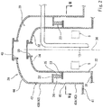
Fig. 1 is a vertical sectional view of a double-shell ship tank according to Embodiment 1 of the present invention. -
Fig. 2 is a sectional view showing an essential part ofFig. 1 in an enlarged manner. -
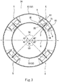
Fig. 3 is a horizontal sectional view schematically showing support mechanisms, the view being taken along line III-III ofFig. 2 . -
Fig. 4 is a horizontal sectional view of one support mechanism. -
Figs. 5A and 5B are vertical sectional views taken along line VA-VA and line VB-VB ofFig. 4 , respectively. -
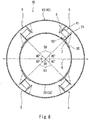
Fig. 6 is a horizontal sectional view schematically showing support mechanisms according to one variation of Embodiment 1. -
Fig. 7 is a horizontal sectional view schematically showing support mechanisms of a double-shell ship tank according to Embodiment 2 of the present invention. -
Fig. 8 is a horizontal sectional view schematically showing support mechanisms of a double-shell ship tank according toEmbodiment 3 of the present invention. -
Fig. 1 shows a double-shell ship tank 2A mounted on a ship 1, such as a liquefied gas carrier, according to Embodiment 1 of the present invention. - Specifically, the double-
shell tank 2A includes aninner shell 3 and an outer shell 4. The outer shell 4 surrounds aspace 20 formed around theinner shell 3. In the present embodiment, thespace 20 between theinner shell 3 and the outer shell 4 is a vacuum space. However, as an alternative, thespace 20 between theinner shell 3 and the outer shell 4 may be filled with a gas having low thermal conductivity, such as argon gas. - The
inner shell 3 includes an inner shellmain part 31 storing a liquefied gas and aninner shell dome 32 protruding upward from the inner shellmain part 31. In the present embodiment, the axial direction of theinner shell dome 32 is parallel to the vertical direction. However, as an alternative, the axial direction of theinner shell dome 32 may be slightly inclined relative to the vertical direction. In the present embodiment, theinner shell dome 32 is provided with amanhole 30 intended for inspection of the inside of the inner shell. However, as an alternative, the inner shellmain part 31 may be provided with themanhole 30. - In the present embodiment, the inner shell
main part 31 is cylindrical and extends in the horizontal direction. However, as an alternative, the inner shellmain part 31 may be spherical or rectangular, for example. To be more specific, the inner shellmain part 31 includes: a body portion that extends laterally with a constant cross-sectional shape; and hemispherical sealing portions that seal openings on both sides of the body portion. Alternatively, each sealing portion may have a flat shape perpendicular to the body portion or may be dish-shaped. - For example, the liquefied gas stored in the inner shell
main part 31 is liquefied petroleum gas (LPG, about -45°C), liquefied ethylene gas (LEG, about -100°C), liquefied natural gas (LNG, about -160°C), liquefied hydrogen (LH2, about -250°C), or liquefied helium (LHe, about -270°C). - The outer shell 4 includes an outer shell
main part 41 surrounding the inner shellmain part 31 and anouter shell dome 42 surrounding theinner shell dome 32. That is, the outer shellmain part 41 has the shape of the inner shellmain part 31, but is larger than the inner shellmain part 31, and theouter shell dome 42 has the shape of theinner shell dome 32, but is larger than theinner shell dome 32. Alternatively, the shape of theouter shell dome 42 may be slightly different from the shape of theinner shell dome 32. Theouter shell dome 42 is provided with amanhole 40 at a position corresponding to the position of theinner shell dome 32. - A pair of
outer bases 12 spaced apart from each other in the axial direction of the outer shellmain part 41 is provided on a ship bottom 11, and the outer shellmain part 41 is supported by theouter bases 12. Between the inner shellmain part 31 and the outer shellmain part 41, a pair ofinner bases 21 is disposed at positions corresponding to the positions of theouter bases 12. Theinner bases 21 support the inner shellmain part 31 in such a manner that the inner shellmain part 31 is slidable in the axial direction thereof. Theinner bases 21 support the inner shellmain part 31 in such a slidable manner so as to accommodate thermal contraction of the inner shellmain part 31 in the axial direction when the liquefied gas is fed into theinner shell 3. - The double-
shell tank 2A is provided withvarious pipes 13, such as a liquefied gas pipe and an electric wire pipe. Thepipes 13 penetrate theinner shell dome 32 and theouter shell dome 42. It should be noted thatFig. 1 shows only one pipe that represents thepipes 13. - Next, the
inner shell dome 32 and theouter shell dome 42 are described in detail with reference toFig. 2 andFig. 3 . - In the present embodiment, each of the
inner shell dome 32 and theouter shell dome 42 has a round sectional shape. However, as an alternative, each of theinner shell dome 32 and theouter shell dome 42 may have an ellipsoidal sectional shape, for example. In the present embodiment, theinner shell dome 32 has acentral axis 36, which coincides with the central axis of theouter shell dome 42. However, as an alternative, thecentral axis 36 of theinner shell dome 32 may deviate from the central axis of theouter shell dome 42. - The
inner shell dome 32 includes: aperipheral wall 33 extending upward from the inner shellmain part 31; and a dish-shapedceiling wall 34, which is raised upward from the upper end of theperipheral wall 33. Similarly, theouter shell dome 42 includes: aperipheral wall 43 extending upward from the outer shellmain part 41; and a dish-shapedceiling wall 44, which is raised upward from the upper end of theperipheral wall 43. It should be noted that theceiling walls ceiling walls aforementioned manholes - In the present embodiment, a
bellows pipe 45 is incorporated in theperipheral wall 43 of theouter shell dome 42, and theperipheral wall 43 is divided by thebellows pipe 45 into abase portion 43A and adistal end portion 43B. Theaforementioned pipes 13 penetrate theperipheral wall 33 of theinner shell dome 32 and thedistal end portion 43B of theperipheral wall 43 of theouter shell dome 42. Alternatively, thepipes 13 may penetrate theceiling wall 34 of theinner shell dome 32 and theceiling wall 44 of theouter shell dome 42. Further alternatively, thepipes 13 may be bent at a position between theinner shell dome 32 and theouter shell dome 42, and may penetrate theperipheral wall 33 of theinner shell dome 32 and theceiling wall 44 of theouter shell dome 42, or may penetrate theceiling wall 34 of theinner shell dome 32 and theperipheral wall 43 of theouter shell dome 42. - A first
annular plate 22 is fixed to the inner peripheral surface of thedistal end portion 43B of theperipheral wall 43 of theouter shell dome 42. A secondannular plate 23 facing the firstannular plate 22 is fixed to the outer peripheral surface of theperipheral wall 43 of theinner shell dome 32. In the illustrated example, the secondannular plate 23 is positioned below the firstannular plate 22. However, as an alternative, the secondannular plate 23 may be positioned above the firstannular plate 22. The firstannular plate 22 and the secondannular plate 23 are coupled together by a plurality ofcoupling members 25. Eachcoupling member 25 may be pillar-shaped or block-shaped. Accordingly, when the liquefied gas is fed into theinner shell 3, the inner shellmain part 31 thermally contracts, and theinner shell dome 32 moves downward. At the time, the upper portion of theouter shell dome 42 also moves downward together with theinner shell dome 32, causing thebellows pipe 45 to be compressed. - A
tubular blocking member 24, which partitions off thespace 20 in theouter shell dome 42 into a lower region and an upper region, is disposed between the firstannular plate 22 and the secondannular plate 23. The blockingmember 24 is intended for reducing the volume open to the atmosphere when themanhole 40 is opened. However, the position of the blockingmember 24 is not limited to this example. As an alternative example, a tubular protrusion may be provided on each of theceiling wall 34 of theinner shell dome 32 and theceiling wall 44 of theouter shell dome 42 such that the tubular protrusions form a double pipe surrounding themanholes member 24 formed as an annular plate may be disposed between these protrusions. As another alternative example, a plurality of first projection pieces arranged at intervals in the circumferential direction may be provided instead of the firstannular plate 22, and a plurality of second projection pieces facing the first projection pieces may be provided instead of the secondannular plate 23. - Between the
peripheral wall 33 of theinner shell dome 32 and thebase portion 43A of theperipheral wall 43 of theouter shell dome 42, at least threesupport mechanisms 5 are disposed around theinner shell dome 32. Thesesupport mechanisms 5 are intended for restricting the dome-to-dome relative position (the relative position between theinner shell dome 32 and theouter shell dome 42 in the radial direction of the inner shell dome 32). In the present embodiment, foursupport mechanisms 5 are provided. Each of thesupport mechanisms 5 is disposed at a position that is away from thecentral axis 36 of theinner shell dome 32 in an angular direction of 45 degrees relative to the axial direction D of the inner shellmain part 31. However, the angular pitches between thesupport mechanisms 5 need not be equal to each other, but may be unequal to each other. - In the present embodiment, each
support mechanism 5 includes: a pair offirst support members 6 fixed to theouter shell dome 42; onesecond support member 7 fixed to theinner shell dome 32. Thesecond support member 7 is positioned on a reference plane 50 (i.e., a plane that is defined by the axial direction and the radial direction of the inner shell dome 32), which includes thecentral axis 36 of theinner shell dome 32. Thefirst support members 6 are disposed at both sides of thesecond support member 7. - Each
first support member 6 includes, on thesecond support member 7 side, a first supportingsurface 61 parallel to thereference plane 50. Thesecond support member 7 includes a pair of second supportingsurfaces 71 facing the respective first supporting surfaces 61. In the present embodiment, eachfirst support member 6 is a plate whose one main surface is the first supportingsurface 61, and thesecond support member 7 is a plate whose one main surface and another main surface are the second supporting surfaces 71. It should be noted that eachfirst support member 6 need not be a plate, but may have any shape, so long as eachfirst support member 6 includes the first supportingsurface 61. However, if each of thefirst support members 6 and thesecond support member 7 is a plate, the first and thesecond support members - The
second support member 7 protrudes outward in the radial direction from theperipheral wall 33 of theinner shell dome 32. That is, the second supportingsurfaces 71 are parallel to thereference plane 50. At a position where eachsupport mechanism 5 is present, a doublingplate 35 is joined to theperipheral wall 33 of theinner shell dome 32, and thesecond support member 7 is fixed to theperipheral wall 33 via the doublingplate 35. However, the doublingplate 35 may be eliminated, and thesecond support member 7 may be directly fixed to theperipheral wall 33. Meanwhile, eachfirst support member 6 is fixed to thebase portion 43A of theperipheral wall 43 of theouter shell dome 42, and protrudes from thebase portion 43A toward theperipheral wall 33 of theinner shell dome 32 in parallel to thesecond support member 7. - To be more specific, as shown in
Fig. 4 andFig. 5B , on the distal end of a main surface (outer main surface) of eachfirst support member 6, the main surface being the opposite surface to the first supportingsurface 61, a reinforcingplate 62 extending in the axial direction of theinner shell dome 32 is joined perpendicularly to the first supportingsurface 61. Between the reinforcingplate 62 and thebase portion 43A,ribs 63 are provided, which are connected to the upper and lower ends of the outer main surface of thefirst support member 6. - As shown in
Fig. 4 andFig. 5A , on the distal end of each second supportingsurface 71 of thesecond support member 7, a reinforcingplate 72 extending in the axial direction of theinner shell dome 32 is joined perpendicularly to the second supportingsurface 71. Between the reinforcingplate 72 and the doublingplate 35,ribs 73 are provided, which are connected to the upper and lower ends of the second supportingsurface 71. - An insulating
member 55 is interposed between each second supportingsurface 71 and the corresponding first supportingsurface 61. In the present embodiment, the insulatingmember 55 is tubular and extends in a direction orthogonal to thereference plane 50. It should be noted that the axial direction of the insulatingmember 55 need not be parallel to the direction orthogonal to thereference plane 50, but may be slightly inclined relative to the direction orthogonal to thereference plane 50. The tubular insulatingmember 55 may have a round sectional shape or a polygonal sectional shape. - In the present embodiment, each tubular insulating
member 55 is made of glass fiber reinforced plastic (GFRP). However, as an alternative, each tubular insulatingmember 55 may be made of carbon fiber reinforced plastic (CFRP) or a different FRP (e.g., fabric reinforced phenolic resin), or may be made of a metal. - One end and the other end of the tubular insulating
member 55 are held by afirst holding member 8A and asecond holding member 8B, respectively. The insulatingmember 55 is in contact with the first supportingsurface 61 via the first holdingmember 8A, and is fixed to the second supportingsurface 71 via the second holdingmember 8B. The insulatingmember 55 slides along the first supportingsurface 61 together with the first holdingmember 8A.Fig. 3 previously referred to schematically shows eachsupport mechanism 5. InFig. 3 , the sliding movement of the insulatingmember 55 along the first supportingsurface 61 is represented by a gap between the insulatingmember 55 and the first supporting surface 61 (inFig. 3 , theribs members - When the liquefied gas is fed into the
inner shell 3, the temperature of thesecond support member 7, the second holdingmember 8B, and the insulatingmember 55 is lowered, and thesecond support member 7, the second holdingmember 8B, and the insulatingmember 55 thermally contract, which may result in formation of a gap between the first holdingmember 8A and the first supportingsurface 61. That is, the term "slide" or "sliding movement" herein means not only relative movement between two objects that are in physical contact with each other, but also relative movement between two objects that are not in physical contact with each other. - In the present embodiment, each of the first holding
member 8A and the second holdingmember 8B has a shape that allows the tubular insulatingmember 55 to be inserted therein. Specifically, each holding member includes: atubular portion 82, in which the tubular insulatingmember 55 is fitted; and abottom portion 81, which contacts with an end surface of the tubular insulatingmember 55. In the present embodiment, an opening is formed at the center of thebottom portion 81. However, it is not essential that the opening be formed. Thetubular portion 82 is coupled to the insulatingmember 55 by apin 56. Alternatively, each holding member may have a shape that allows the holding member to be inserted in the tubular insulatingmember 55. Further alternatively, each holding member and the insulatingmember 55 may be coupled together, for example, by screws or rivets. - A
lubricating liner 51 is sandwiched between the first holdingmember 8A and the first supportingsurface 61. The thickness of thelubricating liner 51 is not particularly limited, and thelubricating liner 51 may be thin or thick. Thelubricating liner 51 is fixed to the first supportingsurface 61, for example, by screws. Alternatively, thelubricating liner 51 may be fixed to the first holdingmember 8A. Thelubricating liner 51 is made of a favorably slidable material (e.g., fluorine resin or molybdenum disulfide). - As described above, in the double-
shell ship tank 2A of the present embodiment, at least threesupport mechanisms 5 are disposed around theinner shell dome 32, and the insulatingmembers 55 included in eachsupport mechanism 5 are movable in a direction parallel to thereference plane 50. This makes it possible to restrict the dome-to-dome relative position (the relative position between theinner shell dome 32 and theouter shell dome 42 in the radial direction of the inner shell dome 32) while allowing thermal contraction of theinner shell dome 32 in the axial direction and the radial direction. - In addition, since each insulating
member 55 is made of GFRP in the present embodiment, entry of heat via the insulatingmember 55 can be further suppressed. - Moreover, in each
support mechanism 5, the pair offirst support members 6 is disposed at both sides of thesecond support member 7. Therefore, eachsupport mechanism 5 alone can restrict theinner shell dome 32 in the circumferential direction. - Furthermore, since the
space 20 between theinner shell 3 and the outer shell 4 is a vacuum space, the liquefied gas can be kept at low temperatures for a long period of time. - Hereinafter, variations of Embodiment 1 are described. The variations described below, except the second variation, are applicable also as variations of
Embodiments 2 and 3 described below. - Assume that the axial direction D and the width direction of the inner shell
main part 31 are the front-rear direction and the right-left direction, respectively. In this case, the foursupport mechanisms 5 may be disposed such that two of them are positioned at the front and rear of thecentral axis 36 of theinner shell dome 32, respectively, and the other two are positioned at the right and left of thecentral axis 36 of theinner shell dome 32, respectively. In this case, however, although the upper surface of the inner shellmain part 31 is straight in the front-rear direction, the upper surface of the inner shellmain part 31 is curved in the right-left direction, and for this reason, the distance from the inner shellmain part 31 to the right and leftsupport mechanisms 5 is greater than the distance from the inner shellmain part 31 to the front andrear support mechanisms 5. In this respect, by adopting the layout as in the above-described embodiment, the distances from the inner shellmain part 31 to all thesupport mechanisms 5 can be made equal to each other. Consequently, loads exerted on all thesupport mechanisms 5 can be made uniform. - As in a double-
shell ship tank 2B according to one variation shown inFig. 6 , eachsupport mechanism 5 may include: onefirst support member 6 fixed to theinner shell dome 32 and positioned on thereference plane 50; and a pair ofsecond support members 7 fixed to theouter shell dome 42 and disposed at both sides of thefirst support member 6. In this case, eachsecond support member 7 need not be a plate, but may have any shape, so long as eachsecond support member 7 includes the second supportingsurface 71. However, if thefirst support members 6 are fixed to the outer shell 4 and thesecond support member 7 is fixed to theinner shell 3 as in the above-described embodiment, the temperature of each first supportingsurface 61 is kept at substantially ordinary temperatures. Therefore, the sliding performance between the insulatingmember 55 and the first supportingsurface 61 can be designed under ordinary temperature conditions. - It is not essential that the second supporting
surface 71 of thesecond support member 7 be parallel to thereference plane 50. For example, in a case where an end portion of the insulatingmember 55 is cut away diagonally, the second supportingsurface 71 may be inclined relative to thereference plane 50, such that the second supportingsurface 71 extends along the end portion of the insulatingmember 55. In this case, it will suffice if thesecond support member 7 positioned on thereference plane 50 is disposed such that thereference plane 50 passes through at least part of thesecond support member 7. - The insulating
member 55 may be a solid-core block. However, if the insulatingmember 55 is tubular as in the above-described embodiment, entry of heat from the outside of the outer shell 4 into theinner shell 3 via the insulatingmember 55 can be suppressed. It should be noted that in a case where the insulatingmember 55 is a solid-core block, the insulatingmember 55 may be directly fixed to the second supportingsurface 71, and may be directly slid on the first supportingsurface 61. - In a case where flanges are provided on both ends of the tubular insulating
member 55, the insulatingmember 55 can be directly fixed to the second supportingsurface 71, and can be directly slid on the first supportingsurface 61. However, by adopting the configuration as in the above-described embodiment, one end of the simple-shaped tubular insulatingmember 55 can be readily fixed to the second supportingsurface 71 by using the second holdingmember 8B. In addition, the first holdingmember 8A, which holds the other end of the tubular insulatingmember 55, can be contacted with the first supportingsurface 61 over a large area. This makes it possible to allow the tubular insulatingmember 55 to make smooth sliding movement together with the first holdingmember 8A. - It is not essential that the
lubricating liner 51 be sandwiched between the first holdingmember 8A and the first supportingsurface 61. For example, the first holdingmember 8A can be made of a resin with favorable sliding ability. Alternatively, in a case where the first holdingmember 8A is made of a metal, a lubricant may be applied onto the first supportingsurface 61, which contacts with the first holdingmember 8A. However, if thelubricating liner 51 is sandwiched between the first holdingmember 8A and the first supportingsurface 61 as in the above-described embodiment, favorable sliding ability can be obtained with a simple configuration. - The
support mechanisms 5 may be disposed between theperipheral wall 33 of theinner shell dome 32 and thedistal end portion 43B of theperipheral wall 43 of theouter shell dome 42. In this case, the insulatingmember 55 may make the sliding movement only in a direction orthogonal to thecentral axis 36 of theinner shell dome 32. - It is not essential that the
bellows pipe 45 be incorporated in theperipheral wall 43 of theouter shell dome 42. In a case where nobellows pipe 45 is incorporated in theperipheral wall 43, when the liquefied gas is fed into theinner shell 3 and the inner shellmain part 31 thermally contracts, the movement of theinner shell dome 32 in the axial direction is allowed by deflection of thepipes 13. - Next, a double-shell ship tank 2C according to Embodiment 2 of the present invention is described with reference to
Fig. 7 . It should be noted that, in the present embodiment and the followingEmbodiment 3, the same components as those described in Embodiment 1 are denoted by the same reference signs as those used in Embodiment 1, and repeating the same descriptions is avoided. - In the present embodiment, each
support mechanism 5 includes: onefirst support member 6 fixed to theouter shell dome 42; a pair ofsecond support members 7 fixed to theinner shell dome 32. The pair ofsecond support members 7 is disposed at both sides of thefirst support member 6, and eachsecond support member 7 is positioned on thecorresponding reference plane 50, which includes thecentral axis 36 of theinner shell dome 32. Eachsecond support member 7 is a plate protruding outward in the radial direction from theperipheral wall 33 of theinner shell dome 32, and includes the second supportingsurface 71 parallel to thereference plane 50. Thefirst support member 6 is substantially trapezoidal when seen in the axial direction of theinner shell dome 32, and includes a pair of first supportingsurfaces 61, each of which is parallel to thecorresponding reference plane 50. Embodiment 2 is the same as Embodiment 1 in the following point: the tubular insulatingmembers 55 are in contact with the first supportingsurfaces 61 via thefirst holding members 8A, and are fixed to the second supportingsurfaces 71 via thesecond holding members 8B. - The present embodiment provides the same advantageous effects as those provided by Embodiment 1.
- It should be noted that, although not illustrated, each
support mechanism 5 may include: a pair offirst support members 6, each of which is fixed to theinner shell dome 32 and positioned on thecorresponding reference plane 50; and one second support member 7 (substantially trapezoidal when seen in the axial direction of the inner shell dome 32) fixed to theouter shell dome 42 and disposed between thefirst support members 6. In this case, eachfirst support member 6 need not be a plate, but may have any shape, so long as eachfirst support member 6 includes the first supportingsurface 61. However, if thefirst support member 6 is fixed to the outer shell 4 and thesecond support members 7 are fixed to theinner shell 3 as in the above-described embodiment, the temperature of each first supportingsurface 61 is kept at substantially ordinary temperatures. Therefore, the sliding performance between the insulatingmember 55 and the first supportingsurface 61 can be designed under ordinary temperature conditions. - Next, a double-
shell ship tank 2D according toEmbodiment 3 of the present invention is described with reference toFig. 8 . - In the present embodiment, each
support mechanism 5 includes: onefirst support member 6 fixed to theouter shell dome 42; and onesecond support member 7 fixed to theinner shell dome 32 and positioned on thereference plane 50. For this reason, thesupport mechanisms 5 are arranged such that they are symmetrically identical with each other alternately. In other words, the positional relationship between thefirst support member 6 and thesecond support member 7 is reversed between adjacent support mechanisms among the foursupport mechanisms 5.Embodiment 3 is the same as Embodiment 1 in the following point: the tubular insulatingmember 55 is in contact with the first supportingsurface 61 via the first holdingmember 8A, and is fixed to the second supportingsurface 71 via the second holdingmember 8B. It should be noted that thefirst support member 6 need not be a plate, but may have any shape, so long as thefirst support member 6 includes the first supportingsurface 61. Similarly, thesecond support member 7 need not be a plate, but may have any shape, so long as thesecond support member 7 includes the second supportingsurface 71. - The present embodiment provides the same advantageous effects as those provided by Embodiment 1. Additionally, the present embodiment makes it possible to simplify the structure of each
support mechanism 5 while restricting the dome-to-dome relative position and restricting theinner shell dome 32 in the circumferential direction, and facilitate position adjustment between thesupport mechanisms 5. It should be noted that, in the present embodiment, it is desirable that the number ofsupport mechanisms 5 be an even number in order to realize the symmetry. If the number ofsupport mechanisms 5 is an even number, in each pair of adjacent support mechanisms 5 (e.g., in a case where the number ofsupport mechanisms 5 is four, in each one of four pairs of adjacent support mechanisms 5), the positional relationship between thefirst support member 6 and thesecond support member 7 is reversed between theadjacent support mechanisms 5. On the other hand, if the number ofsupport mechanisms 5 is an odd number, in each pair ofadjacent support mechanisms 5 except one pair of adjacent support mechanisms 5 (e.g., in a case where the number ofsupport mechanisms 5 is five, in each one of four pairs of adjacent support mechanisms 5), the positional relationship between thefirst support member 6 and thesecond support member 7 is reversed between theadjacent support mechanisms 5. - It should be noted that, although not illustrated, each
support mechanism 5 may include: onefirst support member 6 fixed to theinner shell dome 32 and positioned on thereference plane 50; and onesecond support member 7 fixed to theouter shell dome 42. However, if thefirst support member 6 is fixed to the outer shell 4 and thesecond support member 7 is fixed to theinner shell 3 as in the above-described embodiment, the temperature of the first supportingsurface 61 is kept at substantially ordinary temperatures. Therefore, the sliding performance between the insulatingmember 55 and the first supportingsurface 61 can be designed under ordinary temperature conditions. - It is not essential that the
support mechanisms 5 be arranged such that they are symmetrically identical with each other alternately. For example, assume that the number ofsupport mechanisms 5 is four or more. In this case, so long as the positional relationship between thefirst support member 6 and thesecond support member 7 is reversed between theadjacent support mechanisms 5 in each one of at least four pairs ofadjacent support mechanisms 5, the structure of eachsupport mechanism 5 can be simplified while restricting the dome-to-dome relative position and restricting theinner shell dome 32 in the circumferential direction. For example, in a case where the number ofsupport mechanisms 5 is six and thesupport mechanisms 5 are each categorized into A or B depending on the orientation of eachsupport mechanism 5, thesupport mechanisms 5 may be arranged in the circumferential direction as follows: A1 → A2 → B1 → A3 → B2 → B3 → (A1). In this case, in each one of four pairs (A2 and B1, B1 and A3, A3 and B2, B3 and Al) ofadjacent support mechanisms 5, the positional relationship between thefirst support member 6 and thesecond support member 7 is reversed between theadjacent support mechanisms 5. - The present invention is not limited to the above-described Embodiments 1 to 3. Various modifications can be made without departing from the spirit of the present invention.
- For example, the
support mechanisms 5 need not be disposed between theinner shell dome 32 and theouter shell dome 42, but may be disposed between the inner shellmain part 31 and the outer shellmain part 41. Specifically, thefirst support members 6 may be fixed to one of the inner shellmain part 31 and the outer shellmain part 41, and thesecond support members 7 may be fixed to the other one of the inner shellmain part 31 and the outer shellmain part 41. In this case, between thefirst support members 6 and thesecond support members 7, those fixed to the inner shellmain part 31 are each positioned on thecorresponding reference plane 50. - It is not essential that all the
support mechanisms 5 be disposed at the same height position. Alternatively, thesupport mechanisms 5 may be disposed such that, for example, their positions are vertically shifted from each other alternately. -
- 1 ship
- 2A to 2D double-shell ship tank
- 3 inner shell
- 31 inner shell main part
- 32 inner shell dome
- 36 central axis
- 4 outer shell
- 41 outer shell main part
- 42 outer shell dome
- 5 support mechanism
- 50 reference plane
- 51 lubricating liner
- 55 insulating member
- 6 first support member
- 61 first supporting surface
- 7 second support member
- 71 second supporting surface
- 8A first holding member
- 8B second holding member
Claims (13)
- A double-shell ship tank comprising:an inner shell including an inner shell main part storing a liquefied gas and an inner shell dome protruding upward from the inner shell main part;an outer shell including an outer shell main part surrounding the inner shell main part and an outer shell dome surrounding the inner shell dome; andat least three support mechanisms disposed around the inner shell dome between the inner shell and the outer shell, whereineach of the support mechanisms includes:a first support member fixed to one of the inner shell and the outer shell, the first support member including a first supporting surface parallel to a reference plane that includes a central axis of the inner shell dome;a second support member fixed to the other one of the inner shell and the outer shell, the second support member including a second supporting surface facing the first supporting surface; andan insulating member interposed between the first supporting surface and the second supporting surface, the insulating member being fixed to the second supporting surface and sliding along the first supporting surface, andone of the first support member and the second support member, the one support member being fixed to the inner shell, is positioned on the reference plane.
- The double-shell ship tank according to claim 1, wherein
the first support member is a plate whose one main surface is the first supporting surface, and
the second support member is a plate whose one main surface is the second supporting surface. - The double-shell ship tank according to claim 1 or 2, wherein
the first support member is fixed to the outer shell dome or the outer shell main part, and
the second support member is fixed to the inner shell dome or the inner shell main part. - The double-shell ship tank according to any one of claims 1 to 3, wherein
the insulating member is tubular and extends in a direction orthogonal to the reference plane. - The double-shell ship tank according to claim 4, wherein
each of the support mechanisms includes a first holding member that holds one end of the tubular insulating member and a second holding member that holds another end of the tubular insulating member, and
the tubular insulating member is in contact with the first supporting surface via the first holding member, and is fixed to the second supporting surface via the second holding member. - The double-shell ship tank according to claim 5, wherein
a lubricating liner is sandwiched between the first holding member and the first supporting surface. - The double-shell ship tank according to any one of claims 1 to 6, wherein
the insulating member is made of glass fiber reinforced plastic. - The double-shell ship tank according to any one of claims 1 to 7, wherein
the second support member is a plate whose one main surface and another main surface each serve as the second supporting surface, and
each of the support mechanisms includes a pair of the first support members disposed at both sides of the second support member. - The double-shell ship tank according to any one of claims 1 to 7, wherein
each of the support mechanisms includes one first support member and one second support member, and
a positional relationship between the one first support member and the one second support member is reversed between adjacent support mechanisms among the at least three support mechanisms. - The double-shell ship tank according to any one of claims 1 to 7, wherein
each of the support mechanisms includes one first support member and one second support member,
the at least three support mechanisms comprise four or more support mechanisms, and in each one of at least four pairs of the support mechanisms that are adjacent to each other, a positional relationship between the one first support member and the one second support member is reversed between the adjacent support mechanisms. - The double-shell ship tank according to any one of claims 1 to 10, wherein
a space between the inner shell and the outer shell is a vacuum space. - The double-shell ship tank according to any one of claims 1 to 11, wherein
the inner shell main part is cylindrical and extends in a horizontal direction,
the at least three support mechanisms comprise four support mechanisms that are disposed between the inner shell dome and the outer shell dome, each support mechanism being disposed at a position that is away from the central axis of the inner shell dome in an angular direction of 45 degrees relative to an axial direction of the inner shell main part. - A ship comprising the double-shell ship tank according to any one of claims 1 to 12.
Applications Claiming Priority (2)
| Application Number | Priority Date | Filing Date | Title |
|---|---|---|---|
| JP2015206223 | 2015-10-20 | ||
| PCT/JP2016/081095 WO2017069196A1 (en) | 2015-10-20 | 2016-10-20 | Double-shell tank for ship, and ship |
Publications (3)
| Publication Number | Publication Date |
|---|---|
| EP3366568A1 true EP3366568A1 (en) | 2018-08-29 |
| EP3366568A4 EP3366568A4 (en) | 2019-05-22 |
| EP3366568B1 EP3366568B1 (en) | 2022-04-13 |
Family
ID=58557208
Family Applications (1)
| Application Number | Title | Priority Date | Filing Date |
|---|---|---|---|
| EP16857509.0A Active EP3366568B1 (en) | 2015-10-20 | 2016-10-20 | Double-shell ship tank and ship |
Country Status (5)
| Country | Link |
|---|---|
| EP (1) | EP3366568B1 (en) |
| JP (1) | JP6634090B2 (en) |
| KR (1) | KR102438162B1 (en) |
| CN (1) | CN108137135B (en) |
| WO (1) | WO2017069196A1 (en) |
Cited By (2)
| Publication number | Priority date | Publication date | Assignee | Title |
|---|---|---|---|---|
| EP4201799A4 (en) * | 2020-08-21 | 2024-07-10 | Kawasaki Jukogyo Kabushiki Kaisha | LIQUEFIED GAS TRANSPORT SHIP |
| EP4428430A1 (en) * | 2023-03-10 | 2024-09-11 | Airbus Operations (S.A.S.) | Tank comprising inner and outer enclosures and at least one annular linear connection system connecting said enclosures |
Families Citing this family (6)
| Publication number | Priority date | Publication date | Assignee | Title |
|---|---|---|---|---|
| JP7161293B2 (en) * | 2018-03-02 | 2022-10-26 | 川崎重工業株式会社 | Double-hull tanks and liquefied gas carriers |
| KR102714494B1 (en) | 2020-03-23 | 2024-10-07 | 현대자동차주식회사 | Fire extinguishing system for vehicle |
| KR102315489B1 (en) | 2020-09-01 | 2021-10-21 | 에스탱크엔지니어링(주) | Storage tank for liquefied hydrogen |
| JP7658734B2 (en) * | 2020-10-14 | 2025-04-08 | 川崎重工業株式会社 | Insulated double piping unit for liquefied gas and liquefied gas storage ship equipped with same |
| KR20240030090A (en) | 2022-08-29 | 2024-03-07 | 삼성중공업 주식회사 | Storage tank for ship |
| KR20240048681A (en) | 2022-10-07 | 2024-04-16 | 삼성중공업 주식회사 | Storage tank for ship |
Family Cites Families (16)
| Publication number | Priority date | Publication date | Assignee | Title |
|---|---|---|---|---|
| JPS4310759Y1 (en) * | 1965-12-28 | 1968-05-10 | ||
| JPS4831784U (en) * | 1971-08-20 | 1973-04-17 | ||
| JPS5314766B2 (en) * | 1972-04-21 | 1978-05-19 | ||
| JPS50121986A (en) * | 1974-03-09 | 1975-09-25 | ||
| JPH0447520Y2 (en) * | 1985-10-18 | 1992-11-10 | ||
| JPH06159593A (en) * | 1992-11-13 | 1994-06-07 | Mitsubishi Heavy Ind Ltd | Inner tank supporting structure in double wall storage tank |
| EP2315969A1 (en) * | 2008-08-21 | 2011-05-04 | TGE Marine Gas Engineering GmbH | Device for storing a tank for cryogenic media |
| CN202046614U (en) * | 2011-04-27 | 2011-11-23 | 徐云祥 | Underground double-layer storage tank |
| KR101414787B1 (en) * | 2011-12-13 | 2014-07-03 | 현대중공업 주식회사 | Independent Self Supporting Tank System of LNG Carrrier |
| US9587787B2 (en) * | 2013-04-23 | 2017-03-07 | Kawasaki Jukogyo Kabushiki Kaisha | Support structure of ship tank, and liquefied gas carrier |
| EP2990715B1 (en) * | 2013-04-23 | 2021-07-14 | Kawasaki Jukogyo Kabushiki Kaisha | Double-shell ship tank structure and liquefied gas carrier |
| JP6220164B2 (en) * | 2013-06-19 | 2017-10-25 | 川崎重工業株式会社 | Double shell tank and liquefied gas carrier |
| CN103453311A (en) * | 2013-09-05 | 2013-12-18 | 邓渊 | Double-layered protective low-temperature liquid pressure storage tank |
| KR101812621B1 (en) * | 2013-11-07 | 2017-12-27 | 카와사키 주코교 카부시키 카이샤 | Liquefied-fuel tank and aquatic structure provided with same |
| CN204062463U (en) * | 2014-09-02 | 2014-12-31 | 张家港中集圣达因低温装备有限公司 | LNG ship transfer cask |
| CN204606152U (en) * | 2015-02-17 | 2015-09-02 | 中国海洋石油总公司 | A kind of river and sea type liquified natural gas carrier (LNGC) |
-
2016
- 2016-10-20 JP JP2017545785A patent/JP6634090B2/en active Active
- 2016-10-20 KR KR1020187013097A patent/KR102438162B1/en active Active
- 2016-10-20 WO PCT/JP2016/081095 patent/WO2017069196A1/en not_active Ceased
- 2016-10-20 EP EP16857509.0A patent/EP3366568B1/en active Active
- 2016-10-20 CN CN201680061754.5A patent/CN108137135B/en active Active
Cited By (4)
| Publication number | Priority date | Publication date | Assignee | Title |
|---|---|---|---|---|
| EP4201799A4 (en) * | 2020-08-21 | 2024-07-10 | Kawasaki Jukogyo Kabushiki Kaisha | LIQUEFIED GAS TRANSPORT SHIP |
| EP4428430A1 (en) * | 2023-03-10 | 2024-09-11 | Airbus Operations (S.A.S.) | Tank comprising inner and outer enclosures and at least one annular linear connection system connecting said enclosures |
| FR3146503A1 (en) * | 2023-03-10 | 2024-09-13 | Airbus Operations (S.A.S.) | Tank comprising internal and external enclosures as well as at least one annular linear connection system connecting said enclosures |
| US12455045B2 (en) | 2023-03-10 | 2025-10-28 | Airbus Operations Sas | Tank comprising inner and outer enclosures and at least one annular linear connection system connecting said enclosures |
Also Published As
| Publication number | Publication date |
|---|---|
| JP6634090B2 (en) | 2020-01-22 |
| EP3366568A4 (en) | 2019-05-22 |
| KR20180070608A (en) | 2018-06-26 |
| CN108137135B (en) | 2020-04-07 |
| EP3366568B1 (en) | 2022-04-13 |
| WO2017069196A1 (en) | 2017-04-27 |
| JPWO2017069196A1 (en) | 2018-07-26 |
| KR102438162B1 (en) | 2022-08-31 |
| CN108137135A (en) | 2018-06-08 |
Similar Documents
| Publication | Publication Date | Title |
|---|---|---|
| EP3366568B1 (en) | Double-shell ship tank and ship | |
| EP3012508B1 (en) | Double-shelled tank and liquefied gas transport vessel | |
| US10207775B2 (en) | Double-shell tank and liquefied gas carrier ship | |
| KR101739427B1 (en) | Support structure of ship tank, and liquefied gas carrier | |
| EP3067613B1 (en) | Liquefied-fuel tank and aquatic structure provided with same | |
| KR101616389B1 (en) | Cargo tank structuer and setting up method of the same | |
| KR20150143797A (en) | Double-shell tank structure for use on ship and liquefied gas carrier | |
| US20160230932A1 (en) | Low heat loss cryogenic fluid storage equipment using multilayered cylindrical support | |
| EP3760910B1 (en) | Double-shell tank and liquefied gas carrier ship | |
| KR101861756B1 (en) | Ship tank support structure | |
| JP6670328B2 (en) | Marine double shell tank | |
| KR20230047192A (en) | liquefied gas carrier | |
| KR20250063891A (en) | Storage tank with means for supporting load | |
| JP7144202B2 (en) | Liquefied gas tanks and ships | |
| US20230341090A1 (en) | Fluid storage container | |
| KR20260073489A (en) | Double shell tank | |
| KR20240173422A (en) | Combined support apparatus for cryogenic tank |
Legal Events
| Date | Code | Title | Description |
|---|---|---|---|
| STAA | Information on the status of an ep patent application or granted ep patent |
Free format text: STATUS: THE INTERNATIONAL PUBLICATION HAS BEEN MADE |
|
| PUAI | Public reference made under article 153(3) epc to a published international application that has entered the european phase |
Free format text: ORIGINAL CODE: 0009012 |
|
| STAA | Information on the status of an ep patent application or granted ep patent |
Free format text: STATUS: REQUEST FOR EXAMINATION WAS MADE |
|
| 17P | Request for examination filed |
Effective date: 20180501 |
|
| AK | Designated contracting states |
Kind code of ref document: A1 Designated state(s): AL AT BE BG CH CY CZ DE DK EE ES FI FR GB GR HR HU IE IS IT LI LT LU LV MC MK MT NL NO PL PT RO RS SE SI SK SM TR |
|
| AX | Request for extension of the european patent |
Extension state: BA ME |
|
| DAV | Request for validation of the european patent (deleted) | ||
| DAX | Request for extension of the european patent (deleted) | ||
| A4 | Supplementary search report drawn up and despatched |
Effective date: 20190426 |
|
| RIC1 | Information provided on ipc code assigned before grant |
Ipc: F17C 13/08 20060101ALI20190418BHEP Ipc: B63B 25/16 20060101AFI20190418BHEP |
|
| STAA | Information on the status of an ep patent application or granted ep patent |
Free format text: STATUS: EXAMINATION IS IN PROGRESS |
|
| 17Q | First examination report despatched |
Effective date: 20200317 |
|
| GRAP | Despatch of communication of intention to grant a patent |
Free format text: ORIGINAL CODE: EPIDOSNIGR1 |
|
| STAA | Information on the status of an ep patent application or granted ep patent |
Free format text: STATUS: GRANT OF PATENT IS INTENDED |
|
| GRAJ | Information related to disapproval of communication of intention to grant by the applicant or resumption of examination proceedings by the epo deleted |
Free format text: ORIGINAL CODE: EPIDOSDIGR1 |
|
| GRAP | Despatch of communication of intention to grant a patent |
Free format text: ORIGINAL CODE: EPIDOSNIGR1 |
|
| INTG | Intention to grant announced |
Effective date: 20211013 |
|
| INTG | Intention to grant announced |
Effective date: 20211027 |
|
| GRAS | Grant fee paid |
Free format text: ORIGINAL CODE: EPIDOSNIGR3 |
|
| GRAA | (expected) grant |
Free format text: ORIGINAL CODE: 0009210 |
|
| STAA | Information on the status of an ep patent application or granted ep patent |
Free format text: STATUS: THE PATENT HAS BEEN GRANTED |
|
| AK | Designated contracting states |
Kind code of ref document: B1 Designated state(s): AL AT BE BG CH CY CZ DE DK EE ES FI FR GB GR HR HU IE IS IT LI LT LU LV MC MK MT NL NO PL PT RO RS SE SI SK SM TR |
|
| REG | Reference to a national code |
Ref country code: GB Ref legal event code: FG4D |
|
| REG | Reference to a national code |
Ref country code: CH Ref legal event code: EP |
|
| REG | Reference to a national code |
Ref country code: DE Ref legal event code: R096 Ref document number: 602016071149 Country of ref document: DE |
|
| REG | Reference to a national code |
Ref country code: IE Ref legal event code: FG4D |
|
| REG | Reference to a national code |
Ref country code: AT Ref legal event code: REF Ref document number: 1483219 Country of ref document: AT Kind code of ref document: T Effective date: 20220515 |
|
| REG | Reference to a national code |
Ref country code: NO Ref legal event code: T2 Effective date: 20220413 |
|
| REG | Reference to a national code |
Ref country code: LT Ref legal event code: MG9D |
|
| REG | Reference to a national code |
Ref country code: NL Ref legal event code: MP Effective date: 20220413 |
|
| REG | Reference to a national code |
Ref country code: AT Ref legal event code: MK05 Ref document number: 1483219 Country of ref document: AT Kind code of ref document: T Effective date: 20220413 |
|
| PG25 | Lapsed in a contracting state [announced via postgrant information from national office to epo] |
Ref country code: NL Free format text: LAPSE BECAUSE OF FAILURE TO SUBMIT A TRANSLATION OF THE DESCRIPTION OR TO PAY THE FEE WITHIN THE PRESCRIBED TIME-LIMIT Effective date: 20220413 |
|
| PG25 | Lapsed in a contracting state [announced via postgrant information from national office to epo] |
Ref country code: SE Free format text: LAPSE BECAUSE OF FAILURE TO SUBMIT A TRANSLATION OF THE DESCRIPTION OR TO PAY THE FEE WITHIN THE PRESCRIBED TIME-LIMIT Effective date: 20220413 Ref country code: PT Free format text: LAPSE BECAUSE OF FAILURE TO SUBMIT A TRANSLATION OF THE DESCRIPTION OR TO PAY THE FEE WITHIN THE PRESCRIBED TIME-LIMIT Effective date: 20220816 Ref country code: LT Free format text: LAPSE BECAUSE OF FAILURE TO SUBMIT A TRANSLATION OF THE DESCRIPTION OR TO PAY THE FEE WITHIN THE PRESCRIBED TIME-LIMIT Effective date: 20220413 Ref country code: HR Free format text: LAPSE BECAUSE OF FAILURE TO SUBMIT A TRANSLATION OF THE DESCRIPTION OR TO PAY THE FEE WITHIN THE PRESCRIBED TIME-LIMIT Effective date: 20220413 Ref country code: GR Free format text: LAPSE BECAUSE OF FAILURE TO SUBMIT A TRANSLATION OF THE DESCRIPTION OR TO PAY THE FEE WITHIN THE PRESCRIBED TIME-LIMIT Effective date: 20220714 Ref country code: FI Free format text: LAPSE BECAUSE OF FAILURE TO SUBMIT A TRANSLATION OF THE DESCRIPTION OR TO PAY THE FEE WITHIN THE PRESCRIBED TIME-LIMIT Effective date: 20220413 Ref country code: ES Free format text: LAPSE BECAUSE OF FAILURE TO SUBMIT A TRANSLATION OF THE DESCRIPTION OR TO PAY THE FEE WITHIN THE PRESCRIBED TIME-LIMIT Effective date: 20220413 Ref country code: BG Free format text: LAPSE BECAUSE OF FAILURE TO SUBMIT A TRANSLATION OF THE DESCRIPTION OR TO PAY THE FEE WITHIN THE PRESCRIBED TIME-LIMIT Effective date: 20220713 Ref country code: AT Free format text: LAPSE BECAUSE OF FAILURE TO SUBMIT A TRANSLATION OF THE DESCRIPTION OR TO PAY THE FEE WITHIN THE PRESCRIBED TIME-LIMIT Effective date: 20220413 |
|
| PG25 | Lapsed in a contracting state [announced via postgrant information from national office to epo] |
Ref country code: RS Free format text: LAPSE BECAUSE OF FAILURE TO SUBMIT A TRANSLATION OF THE DESCRIPTION OR TO PAY THE FEE WITHIN THE PRESCRIBED TIME-LIMIT Effective date: 20220413 Ref country code: PL Free format text: LAPSE BECAUSE OF FAILURE TO SUBMIT A TRANSLATION OF THE DESCRIPTION OR TO PAY THE FEE WITHIN THE PRESCRIBED TIME-LIMIT Effective date: 20220413 Ref country code: LV Free format text: LAPSE BECAUSE OF FAILURE TO SUBMIT A TRANSLATION OF THE DESCRIPTION OR TO PAY THE FEE WITHIN THE PRESCRIBED TIME-LIMIT Effective date: 20220413 Ref country code: IS Free format text: LAPSE BECAUSE OF FAILURE TO SUBMIT A TRANSLATION OF THE DESCRIPTION OR TO PAY THE FEE WITHIN THE PRESCRIBED TIME-LIMIT Effective date: 20220813 |
|
| REG | Reference to a national code |
Ref country code: DE Ref legal event code: R097 Ref document number: 602016071149 Country of ref document: DE |
|
| PG25 | Lapsed in a contracting state [announced via postgrant information from national office to epo] |
Ref country code: SM Free format text: LAPSE BECAUSE OF FAILURE TO SUBMIT A TRANSLATION OF THE DESCRIPTION OR TO PAY THE FEE WITHIN THE PRESCRIBED TIME-LIMIT Effective date: 20220413 Ref country code: SK Free format text: LAPSE BECAUSE OF FAILURE TO SUBMIT A TRANSLATION OF THE DESCRIPTION OR TO PAY THE FEE WITHIN THE PRESCRIBED TIME-LIMIT Effective date: 20220413 Ref country code: RO Free format text: LAPSE BECAUSE OF FAILURE TO SUBMIT A TRANSLATION OF THE DESCRIPTION OR TO PAY THE FEE WITHIN THE PRESCRIBED TIME-LIMIT Effective date: 20220413 Ref country code: EE Free format text: LAPSE BECAUSE OF FAILURE TO SUBMIT A TRANSLATION OF THE DESCRIPTION OR TO PAY THE FEE WITHIN THE PRESCRIBED TIME-LIMIT Effective date: 20220413 Ref country code: DK Free format text: LAPSE BECAUSE OF FAILURE TO SUBMIT A TRANSLATION OF THE DESCRIPTION OR TO PAY THE FEE WITHIN THE PRESCRIBED TIME-LIMIT Effective date: 20220413 Ref country code: CZ Free format text: LAPSE BECAUSE OF FAILURE TO SUBMIT A TRANSLATION OF THE DESCRIPTION OR TO PAY THE FEE WITHIN THE PRESCRIBED TIME-LIMIT Effective date: 20220413 |
|
| PLBE | No opposition filed within time limit |
Free format text: ORIGINAL CODE: 0009261 |
|
| STAA | Information on the status of an ep patent application or granted ep patent |
Free format text: STATUS: NO OPPOSITION FILED WITHIN TIME LIMIT |
|
| 26N | No opposition filed |
Effective date: 20230116 |
|
| PG25 | Lapsed in a contracting state [announced via postgrant information from national office to epo] |
Ref country code: AL Free format text: LAPSE BECAUSE OF FAILURE TO SUBMIT A TRANSLATION OF THE DESCRIPTION OR TO PAY THE FEE WITHIN THE PRESCRIBED TIME-LIMIT Effective date: 20220413 |
|
| REG | Reference to a national code |
Ref country code: DE Ref legal event code: R119 Ref document number: 602016071149 Country of ref document: DE |
|
| PG25 | Lapsed in a contracting state [announced via postgrant information from national office to epo] |
Ref country code: SI Free format text: LAPSE BECAUSE OF FAILURE TO SUBMIT A TRANSLATION OF THE DESCRIPTION OR TO PAY THE FEE WITHIN THE PRESCRIBED TIME-LIMIT Effective date: 20220413 Ref country code: MC Free format text: LAPSE BECAUSE OF FAILURE TO SUBMIT A TRANSLATION OF THE DESCRIPTION OR TO PAY THE FEE WITHIN THE PRESCRIBED TIME-LIMIT Effective date: 20220413 |
|
| REG | Reference to a national code |
Ref country code: CH Ref legal event code: PL |
|
| REG | Reference to a national code |
Ref country code: BE Ref legal event code: MM Effective date: 20221031 |
|
| GBPC | Gb: european patent ceased through non-payment of renewal fee |
Effective date: 20221020 |
|
| PG25 | Lapsed in a contracting state [announced via postgrant information from national office to epo] |
Ref country code: LU Free format text: LAPSE BECAUSE OF NON-PAYMENT OF DUE FEES Effective date: 20221020 |
|
| PG25 | Lapsed in a contracting state [announced via postgrant information from national office to epo] |
Ref country code: LI Free format text: LAPSE BECAUSE OF NON-PAYMENT OF DUE FEES Effective date: 20221031 Ref country code: FR Free format text: LAPSE BECAUSE OF NON-PAYMENT OF DUE FEES Effective date: 20221031 Ref country code: DE Free format text: LAPSE BECAUSE OF NON-PAYMENT OF DUE FEES Effective date: 20230503 Ref country code: CH Free format text: LAPSE BECAUSE OF NON-PAYMENT OF DUE FEES Effective date: 20221031 |
|
| PG25 | Lapsed in a contracting state [announced via postgrant information from national office to epo] |
Ref country code: BE Free format text: LAPSE BECAUSE OF NON-PAYMENT OF DUE FEES Effective date: 20221031 |
|
| PG25 | Lapsed in a contracting state [announced via postgrant information from national office to epo] |
Ref country code: IE Free format text: LAPSE BECAUSE OF NON-PAYMENT OF DUE FEES Effective date: 20221020 Ref country code: GB Free format text: LAPSE BECAUSE OF NON-PAYMENT OF DUE FEES Effective date: 20221020 |
|
| PG25 | Lapsed in a contracting state [announced via postgrant information from national office to epo] |
Ref country code: IT Free format text: LAPSE BECAUSE OF FAILURE TO SUBMIT A TRANSLATION OF THE DESCRIPTION OR TO PAY THE FEE WITHIN THE PRESCRIBED TIME-LIMIT Effective date: 20220413 |
|
| PG25 | Lapsed in a contracting state [announced via postgrant information from national office to epo] |
Ref country code: HU Free format text: LAPSE BECAUSE OF FAILURE TO SUBMIT A TRANSLATION OF THE DESCRIPTION OR TO PAY THE FEE WITHIN THE PRESCRIBED TIME-LIMIT; INVALID AB INITIO Effective date: 20161020 |
|
| PG25 | Lapsed in a contracting state [announced via postgrant information from national office to epo] |
Ref country code: CY Free format text: LAPSE BECAUSE OF FAILURE TO SUBMIT A TRANSLATION OF THE DESCRIPTION OR TO PAY THE FEE WITHIN THE PRESCRIBED TIME-LIMIT Effective date: 20220413 |
|
| PG25 | Lapsed in a contracting state [announced via postgrant information from national office to epo] |
Ref country code: MK Free format text: LAPSE BECAUSE OF FAILURE TO SUBMIT A TRANSLATION OF THE DESCRIPTION OR TO PAY THE FEE WITHIN THE PRESCRIBED TIME-LIMIT Effective date: 20220413 |
|
| PG25 | Lapsed in a contracting state [announced via postgrant information from national office to epo] |
Ref country code: TR Free format text: LAPSE BECAUSE OF FAILURE TO SUBMIT A TRANSLATION OF THE DESCRIPTION OR TO PAY THE FEE WITHIN THE PRESCRIBED TIME-LIMIT Effective date: 20220413 |
|
| PG25 | Lapsed in a contracting state [announced via postgrant information from national office to epo] |
Ref country code: MT Free format text: LAPSE BECAUSE OF FAILURE TO SUBMIT A TRANSLATION OF THE DESCRIPTION OR TO PAY THE FEE WITHIN THE PRESCRIBED TIME-LIMIT Effective date: 20220413 |
|
| PG25 | Lapsed in a contracting state [announced via postgrant information from national office to epo] |
Ref country code: BG Free format text: LAPSE BECAUSE OF FAILURE TO SUBMIT A TRANSLATION OF THE DESCRIPTION OR TO PAY THE FEE WITHIN THE PRESCRIBED TIME-LIMIT Effective date: 20220413 |
|
| PG25 | Lapsed in a contracting state [announced via postgrant information from national office to epo] |
Ref country code: BG Free format text: LAPSE BECAUSE OF FAILURE TO SUBMIT A TRANSLATION OF THE DESCRIPTION OR TO PAY THE FEE WITHIN THE PRESCRIBED TIME-LIMIT Effective date: 20220413 |
|
| PGFP | Annual fee paid to national office [announced via postgrant information from national office to epo] |
Ref country code: NO Payment date: 20251009 Year of fee payment: 10 |