EP3366378A1 - Coating spraying device for stabilizer, coating equipment, and coating method - Google Patents
Coating spraying device for stabilizer, coating equipment, and coating method Download PDFInfo
- Publication number
- EP3366378A1 EP3366378A1 EP16857333.5A EP16857333A EP3366378A1 EP 3366378 A1 EP3366378 A1 EP 3366378A1 EP 16857333 A EP16857333 A EP 16857333A EP 3366378 A1 EP3366378 A1 EP 3366378A1
- Authority
- EP
- European Patent Office
- Prior art keywords
- powder paint
- stabilizer
- flexible tubes
- nozzles
- frame
- Prior art date
- Legal status (The legal status is an assumption and is not a legal conclusion. Google has not performed a legal analysis and makes no representation as to the accuracy of the status listed.)
- Granted
Links
Images




Classifications
-
- B—PERFORMING OPERATIONS; TRANSPORTING
- B05—SPRAYING OR ATOMISING IN GENERAL; APPLYING FLUENT MATERIALS TO SURFACES, IN GENERAL
- B05B—SPRAYING APPARATUS; ATOMISING APPARATUS; NOZZLES
- B05B5/00—Electrostatic spraying apparatus; Spraying apparatus with means for charging the spray electrically; Apparatus for spraying liquids or other fluent materials by other electric means
- B05B5/08—Plant for applying liquids or other fluent materials to objects
- B05B5/087—Arrangements of electrodes, e.g. of charging, shielding, collecting electrodes
-
- B—PERFORMING OPERATIONS; TRANSPORTING
- B05—SPRAYING OR ATOMISING IN GENERAL; APPLYING FLUENT MATERIALS TO SURFACES, IN GENERAL
- B05B—SPRAYING APPARATUS; ATOMISING APPARATUS; NOZZLES
- B05B12/00—Arrangements for controlling delivery; Arrangements for controlling the spray area
- B05B12/16—Arrangements for controlling delivery; Arrangements for controlling the spray area for controlling the spray area
- B05B12/18—Arrangements for controlling delivery; Arrangements for controlling the spray area for controlling the spray area using fluids, e.g. gas streams
-
- B—PERFORMING OPERATIONS; TRANSPORTING
- B05—SPRAYING OR ATOMISING IN GENERAL; APPLYING FLUENT MATERIALS TO SURFACES, IN GENERAL
- B05B—SPRAYING APPARATUS; ATOMISING APPARATUS; NOZZLES
- B05B13/00—Machines or plants for applying liquids or other fluent materials to surfaces of objects or other work by spraying, not covered by groups B05B1/00 - B05B11/00
- B05B13/02—Means for supporting work; Arrangement or mounting of spray heads; Adaptation or arrangement of means for feeding work
- B05B13/0221—Means for supporting work; Arrangement or mounting of spray heads; Adaptation or arrangement of means for feeding work characterised by the means for moving or conveying the objects or other work, e.g. conveyor belts
- B05B13/0264—Overhead conveying means, i.e. the object or other work being suspended from the conveying means; Details thereof, e.g. hanging hooks
-
- B—PERFORMING OPERATIONS; TRANSPORTING
- B05—SPRAYING OR ATOMISING IN GENERAL; APPLYING FLUENT MATERIALS TO SURFACES, IN GENERAL
- B05B—SPRAYING APPARATUS; ATOMISING APPARATUS; NOZZLES
- B05B13/00—Machines or plants for applying liquids or other fluent materials to surfaces of objects or other work by spraying, not covered by groups B05B1/00 - B05B11/00
- B05B13/02—Means for supporting work; Arrangement or mounting of spray heads; Adaptation or arrangement of means for feeding work
- B05B13/0278—Arrangement or mounting of spray heads
-
- B—PERFORMING OPERATIONS; TRANSPORTING
- B05—SPRAYING OR ATOMISING IN GENERAL; APPLYING FLUENT MATERIALS TO SURFACES, IN GENERAL
- B05B—SPRAYING APPARATUS; ATOMISING APPARATUS; NOZZLES
- B05B5/00—Electrostatic spraying apparatus; Spraying apparatus with means for charging the spray electrically; Apparatus for spraying liquids or other fluent materials by other electric means
- B05B5/025—Discharge apparatus, e.g. electrostatic spray guns
-
- B—PERFORMING OPERATIONS; TRANSPORTING
- B05—SPRAYING OR ATOMISING IN GENERAL; APPLYING FLUENT MATERIALS TO SURFACES, IN GENERAL
- B05B—SPRAYING APPARATUS; ATOMISING APPARATUS; NOZZLES
- B05B5/00—Electrostatic spraying apparatus; Spraying apparatus with means for charging the spray electrically; Apparatus for spraying liquids or other fluent materials by other electric means
- B05B5/08—Plant for applying liquids or other fluent materials to objects
- B05B5/082—Plant for applying liquids or other fluent materials to objects characterised by means for supporting, holding or conveying the objects
-
- B—PERFORMING OPERATIONS; TRANSPORTING
- B05—SPRAYING OR ATOMISING IN GENERAL; APPLYING FLUENT MATERIALS TO SURFACES, IN GENERAL
- B05B—SPRAYING APPARATUS; ATOMISING APPARATUS; NOZZLES
- B05B7/00—Spraying apparatus for discharge of liquids or other fluent materials from two or more sources, e.g. of liquid and air, of powder and gas
- B05B7/14—Spraying apparatus for discharge of liquids or other fluent materials from two or more sources, e.g. of liquid and air, of powder and gas designed for spraying particulate materials
- B05B7/1404—Arrangements for supplying particulate material
- B05B7/1454—Arrangements for supplying particulate material comprising means for supplying collected oversprayed particulate material
-
- B—PERFORMING OPERATIONS; TRANSPORTING
- B05—SPRAYING OR ATOMISING IN GENERAL; APPLYING FLUENT MATERIALS TO SURFACES, IN GENERAL
- B05D—PROCESSES FOR APPLYING FLUENT MATERIALS TO SURFACES, IN GENERAL
- B05D1/00—Processes for applying liquids or other fluent materials
- B05D1/02—Processes for applying liquids or other fluent materials performed by spraying
- B05D1/04—Processes for applying liquids or other fluent materials performed by spraying involving the use of an electrostatic field
- B05D1/06—Applying particulate materials
-
- B—PERFORMING OPERATIONS; TRANSPORTING
- B05—SPRAYING OR ATOMISING IN GENERAL; APPLYING FLUENT MATERIALS TO SURFACES, IN GENERAL
- B05D—PROCESSES FOR APPLYING FLUENT MATERIALS TO SURFACES, IN GENERAL
- B05D3/00—Pretreatment of surfaces to which liquids or other fluent materials are to be applied; After-treatment of applied coatings, e.g. intermediate treating of an applied coating preparatory to subsequent applications of liquids or other fluent materials
- B05D3/02—Pretreatment of surfaces to which liquids or other fluent materials are to be applied; After-treatment of applied coatings, e.g. intermediate treating of an applied coating preparatory to subsequent applications of liquids or other fluent materials by baking
- B05D3/0254—After-treatment
- B05D3/0272—After-treatment with ovens
-
- B—PERFORMING OPERATIONS; TRANSPORTING
- B05—SPRAYING OR ATOMISING IN GENERAL; APPLYING FLUENT MATERIALS TO SURFACES, IN GENERAL
- B05D—PROCESSES FOR APPLYING FLUENT MATERIALS TO SURFACES, IN GENERAL
- B05D3/00—Pretreatment of surfaces to which liquids or other fluent materials are to be applied; After-treatment of applied coatings, e.g. intermediate treating of an applied coating preparatory to subsequent applications of liquids or other fluent materials
- B05D3/04—Pretreatment of surfaces to which liquids or other fluent materials are to be applied; After-treatment of applied coatings, e.g. intermediate treating of an applied coating preparatory to subsequent applications of liquids or other fluent materials by exposure to gases
- B05D3/0406—Pretreatment of surfaces to which liquids or other fluent materials are to be applied; After-treatment of applied coatings, e.g. intermediate treating of an applied coating preparatory to subsequent applications of liquids or other fluent materials by exposure to gases the gas being air
-
- B—PERFORMING OPERATIONS; TRANSPORTING
- B60—VEHICLES IN GENERAL
- B60G—VEHICLE SUSPENSION ARRANGEMENTS
- B60G21/00—Interconnection systems for two or more resiliently-suspended wheels, e.g. for stabilising a vehicle body with respect to acceleration, deceleration or centrifugal forces
- B60G21/02—Interconnection systems for two or more resiliently-suspended wheels, e.g. for stabilising a vehicle body with respect to acceleration, deceleration or centrifugal forces permanently interconnected
- B60G21/04—Interconnection systems for two or more resiliently-suspended wheels, e.g. for stabilising a vehicle body with respect to acceleration, deceleration or centrifugal forces permanently interconnected mechanically
- B60G21/05—Interconnection systems for two or more resiliently-suspended wheels, e.g. for stabilising a vehicle body with respect to acceleration, deceleration or centrifugal forces permanently interconnected mechanically between wheels on the same axle but on different sides of the vehicle, i.e. the left and right wheel suspensions being interconnected
- B60G21/055—Stabiliser bars
-
- B—PERFORMING OPERATIONS; TRANSPORTING
- B05—SPRAYING OR ATOMISING IN GENERAL; APPLYING FLUENT MATERIALS TO SURFACES, IN GENERAL
- B05B—SPRAYING APPARATUS; ATOMISING APPARATUS; NOZZLES
- B05B15/00—Details of spraying plant or spraying apparatus not otherwise provided for; Accessories
- B05B15/60—Arrangements for mounting, supporting or holding spraying apparatus
- B05B15/65—Mounting arrangements for fluid connection of the spraying apparatus or its outlets to flow conduits
- B05B15/652—Mounting arrangements for fluid connection of the spraying apparatus or its outlets to flow conduits whereby the jet can be oriented
- B05B15/654—Mounting arrangements for fluid connection of the spraying apparatus or its outlets to flow conduits whereby the jet can be oriented using universal joints
-
- B—PERFORMING OPERATIONS; TRANSPORTING
- B05—SPRAYING OR ATOMISING IN GENERAL; APPLYING FLUENT MATERIALS TO SURFACES, IN GENERAL
- B05B—SPRAYING APPARATUS; ATOMISING APPARATUS; NOZZLES
- B05B5/00—Electrostatic spraying apparatus; Spraying apparatus with means for charging the spray electrically; Apparatus for spraying liquids or other fluent materials by other electric means
- B05B5/025—Discharge apparatus, e.g. electrostatic spray guns
- B05B5/043—Discharge apparatus, e.g. electrostatic spray guns using induction-charging
-
- B—PERFORMING OPERATIONS; TRANSPORTING
- B05—SPRAYING OR ATOMISING IN GENERAL; APPLYING FLUENT MATERIALS TO SURFACES, IN GENERAL
- B05D—PROCESSES FOR APPLYING FLUENT MATERIALS TO SURFACES, IN GENERAL
- B05D2202/00—Metallic substrate
- B05D2202/10—Metallic substrate based on Fe
-
- B—PERFORMING OPERATIONS; TRANSPORTING
- B05—SPRAYING OR ATOMISING IN GENERAL; APPLYING FLUENT MATERIALS TO SURFACES, IN GENERAL
- B05D—PROCESSES FOR APPLYING FLUENT MATERIALS TO SURFACES, IN GENERAL
- B05D7/00—Processes, other than flocking, specially adapted for applying liquids or other fluent materials to particular surfaces or for applying particular liquids or other fluent materials
- B05D7/14—Processes, other than flocking, specially adapted for applying liquids or other fluent materials to particular surfaces or for applying particular liquids or other fluent materials to metal, e.g. car bodies
-
- B—PERFORMING OPERATIONS; TRANSPORTING
- B60—VEHICLES IN GENERAL
- B60G—VEHICLE SUSPENSION ARRANGEMENTS
- B60G2202/00—Indexing codes relating to the type of spring, damper or actuator
- B60G2202/10—Type of spring
- B60G2202/13—Torsion spring
- B60G2202/135—Stabiliser bar and/or tube
-
- B—PERFORMING OPERATIONS; TRANSPORTING
- B60—VEHICLES IN GENERAL
- B60G—VEHICLE SUSPENSION ARRANGEMENTS
- B60G2206/00—Indexing codes related to the manufacturing of suspensions: constructional features, the materials used, procedures or tools
- B60G2206/01—Constructional features of suspension elements, e.g. arms, dampers, springs
- B60G2206/40—Constructional features of dampers and/or springs
- B60G2206/42—Springs
- B60G2206/427—Stabiliser bars or tubes
-
- B—PERFORMING OPERATIONS; TRANSPORTING
- B60—VEHICLES IN GENERAL
- B60G—VEHICLE SUSPENSION ARRANGEMENTS
- B60G2206/00—Indexing codes related to the manufacturing of suspensions: constructional features, the materials used, procedures or tools
- B60G2206/01—Constructional features of suspension elements, e.g. arms, dampers, springs
- B60G2206/80—Manufacturing procedures
-
- B—PERFORMING OPERATIONS; TRANSPORTING
- B60—VEHICLES IN GENERAL
- B60G—VEHICLE SUSPENSION ARRANGEMENTS
- B60G2206/00—Indexing codes related to the manufacturing of suspensions: constructional features, the materials used, procedures or tools
- B60G2206/01—Constructional features of suspension elements, e.g. arms, dampers, springs
- B60G2206/80—Manufacturing procedures
- B60G2206/81—Shaping
- B60G2206/8112—Shaping by thermal spraying of molten material
Definitions
- the present invention relates to a paint spraying apparatus, a coating installation, and a coating method for use in coating a vehicle stabilizer.
- a stabilizer arranged in a suspension mechanism part of a vehicle which is formed of a steel pipe or a solid rod-shaped steel material, includes a torsion portion (a twisted portion) which extends in a width direction of the vehicle, and a pair of arm portions (arms) connected via bent portions on both ends of the torsion portion. On a distal end of each of the arm portions, an eye portion is formed.
- the torsion portion of the stabilizer is supported by a vehicle body via a rubber bushing, etc.
- the eye portion is connected to a suspension arm, etc., via a connecting member such as a stabilizer link.
- the arm portion, the bent portion, and the torsion portion function as a spring in reaction to a rolling behavior of the vehicle body, roll stiffness of the vehicle can be enhanced.
- a pair of eye portions are formed.
- flat-shaped fastening surfaces are formed, respectively, and through-holes are formed in the respective fastening surfaces.
- a connecting member such as a bolt or a stabilizer link is inserted.
- the eye portion is connected to a suspension mechanism member such as the suspension arm through the connecting member.
- Patent Literature 2 describes an example of a method of manufacturing a stabilizer.
- a coating film is formed on a surface of the stabilizer formed of a steel pipe by a coating process.
- electrostatic dry spray coating or fluidized bed coating using powder paint is adopted.
- a coating film is formed on a surface of the steel pipe at a substantially uniform thickness.
- the coating of the stabilizer it is required to make the coating film thick in a stabilizer body portion other than the eye portion, and reduce the thickness of the coating film of the eye portion as compared to the stabilizer body portion.
- a paint is sprayed thickly on the entire stabilizer in a state in which the eye portion is subjected to masking, for example. After that, the masking is removed, and the eye portion is coated thinly by touch-up paint.
- the eye portion may be coated by immersing the eye portion in a dipping tank.
- thinning the coating film of the eye portion by increasing the movement speed of the coating gun at the eye portion as compared to the stabilizer body portion has also been conceived.
- the eye portion is to be masked as in the above-mentioned conventional example, it takes time and trouble to provide a masking member on the eye portion before coating, and remove the masking member after the coating. For this reason, a coating method which uses the masking member is not suitable for mass production.
- the movement speed of the coating gun is increased at the eye portion, and is decreased in the stabilizer body portion.
- the paint since the paint is sprayed on the eye portion in a short time, it is difficult to make the paint adhere to the eye portion evenly, and the thickness of the paint may be varied greatly.
- an object of the present invention is to provide a paint spraying apparatus, a coating installation, and a coating method for a stabilizer, which is cable of forming coating films of different thicknesses in the eye portion of the stabilizer and the stabilizer body portion, and reducing variations in the thickness of the coating film of the eye portion.
- a paint spraying apparatus used in a coating installation includes a supporting structure, a lower nozzle unit provided on the supporting structure and configured to spray powder paint toward a lower eye portion of a stabilizer, and an upper nozzle unit provided on the supporting structure and configured to spray the powder paint toward an upper eye portion of the stabilizer.
- the lower nozzle unit includes a lower frame, a plurality of lower flexible tubes arranged on the lower frame, lower nozzles provided at respective distal ends of the lower flexible tubes, and configured to eject the powder paint, and lower electrodes which provide a charge to the powder paint ejected from the lower nozzles.
- the upper nozzle unit comprises a first frame extending in a first direction, a plurality of first flexible tubes arranged on the first frame, first nozzles provided at respective distal ends of the first flexible tubes, and configured to eject the powder paint, a second frame extending in a second direction different from the direction of the first frame, second flexible tubes arranged on the second frame, second nozzles provided at distal ends of the second flexible tubes, and configured to eject the powder paint, upper electrodes which provide a charge to the powder paint ejected from the first nozzles and the second nozzles, and a paint feed mechanism which supplies the powder paint to the lower flexible tubes, the first flexible tubes, and the second flexible tubes.
- a coating installation includes a hanger including a hook which is inserted into a through-hole of one of eye portions provided on both ends of a stabilizer, an electrostatic gun which sprays charged powder paint on the entire stabilizer suspended by the hanger, thereby making the powder paint adhere to the entire stabilizer at a first thickness, an air injection gun which exfoliates the powder paint adhering to the respective eye portions of the stabilizer by an air blow, the paint spraying apparatus which sprays the powder paint on the respective eye portions, thereby making the powder paint adhere to the eye portions at a second thickness less than the first thickness, and a heating furnace which bakes the powder paint adhering to the stabilizer.
- the present invention it is possible to form coating films of different thicknesses in the eye portion of the stabilizer and the stabilizer body portion, and reduce variations in the thicknesses of the coating films in one eye portion and the other eye portion.
- a coating installation and a coating method for a stabilizer according to one embodiment will be hereinafter described with reference to FIGS. 1 to 8 .
- FIG. 1 shows a part of a vehicle 11 comprising a vehicle stabilizer 10 (which may be simply referred to as a stabilizer in the present specification).
- the stabilizer 10 is arranged in a suspension mechanism part provided at the lower part of a vehicle body 12.
- the stabilizer 10 includes a stabilizer body portion 20 formed of a rod-shaped steel material, and a pair of eye portions 21 and 22 formed on both ends of the stabilizer body portion 20.
- the stabilizer body portion 20 includes a torsion portion 25, bent portions 26 and 27, and arm portions 28 and 29.
- the torsion portion 25 extends in a width direction (i.e., a direction indicated by arrow W in FIG. 1 ) of the vehicle body 12.
- the arm portions 28 and 29 are continuous with both ends of the torsion portion 25 through their corresponding bent portions 26 and 27.
- the stabilizer 10 is substantially bilaterally symmetric when viewed from the front side of the vehicle 11. Accordingly, the eye portions 21 and 22 are also bilaterally symmetric.
- the shape of the stabilizer 10 is not limited to planar.
- the stabilizer 10 may include one or more bending portions in the torsion portion 25, or one or more bending portions in the arm portions 28 and 29, including a three-dimensional bent configuration.
- the bent portions 26 and 27 may be configured to have a three-dimensional bent configuration, for example, and can be formed into various bent shapes.
- the stabilizer 10 of the present embodiment is a hollow stabilizer.
- the material of the stabilizer 10 is a hollow steel material (a steel pipe), and is formed into a predetermined shape by a bending machine.
- An example of the steel material is a type of steel capable of improving its strength by a heat treatment such as quenching, more specifically, using ASB25N or the like as the material.
- a heat treatment such as quenching, more specifically, using ASB25N or the like as the material.
- Circular through-holes 30 and 31 are formed in the eye portions 21 and 22.
- the through-holes 30 and 31 penetrate the eye portions 21 and 22 in a thickness direction.
- connecting members 32 and 33 FIG. 1
- the connecting members 32 and 33 are fixed to the eye portions 21 and 22 by fixing members such as a nut.
- the arm portions 28 and 29 are connected to suspension arms of the suspension mechanism part, for example, via the connecting members 32 and 33, respectively.
- the torsion portion 25 is supported by a part of the vehicle body 12 (such as a cross-member), for example, via a pair of support portions 34 and 35 ( FIG. 1 ) comprising a rubber bushing, etc.
- a bending force is exerted on the arm portions 28 and 29.
- Bending and torsional force is exerted on the bent portions 26 and 27.
- the torsion portion 25 is also twisted and a repulsive load is produced. As a result, a rolling behavior of the vehicle body 12 is suppressed.
- Coating is applied on a surface of the stabilizer 10 mainly for rust prevention and also in consideration of appearance quality.
- powder electrostatic coating an electrostatic dry spray method
- baking are performed.
- the thickness of a coating film of the eye portions 21 and 22 is, for example 10 to 20 ⁇ m.
- the thickness of a coating film of the stabilizer body portion 20 excluding the eye portions 21 and 22 is, for example, 40 to 120 ⁇ m. In other words, the thickness of the coating film of the eye portions 21 and 22 is less than the thickness of the coating film of the stabilizer body portion 20.
- FIG. 2A schematically shows a coating installation 40 according to one embodiment.
- FIG. 2B is a flowchart indicating an example of a coating method in the order of steps.
- FIG. 3 shows a part of the coating installation 40.
- the coating installation 40 comprises a hanger 41.
- the stabilizer 10 is continuously carried in a state in which it is suspended by the hanger 41.
- the hanger 41 is made of metal.
- a plurality of hangers 41 are provided on a movable body 41a for carrying such as a conveyor chain at a predetermined pitch. Accordingly, the plurality of stabilizers 10 can be moved simultaneously.
- a hook 42 is provided on the lower part of each of the hangers 41.
- the center of gravity G ( FIG. 3 ) of the stabilizer 10 is at a position displaced laterally to the torsion portion 25. Accordingly, when the stabilizer 10 is suspended by inserting the hook 42 into the through-hole 31 of the eye portion 22 on one side, the stabilizer 10 is supported by the hanger 41 in a position inclined obliquely. In other words, the stabilizer 10 is brought to such a state that one of the eye portions, i.e., the eye portion 22, is supported by the hook 42, and the other eye portion, i.e., the eye portion 21, dangles. Further, the stabilizer 10 is continuously moved in a movement path of the coating installation 40 from a main booth 43 ( FIG. 2A ) toward a heating furnace 44. Arrow M in FIG. 2A shows the direction of movement of the stabilizer 10.
- a preprocessing step ST1 in FIG. 2B dirt, oil content, etc., on a surface of the stabilizer 10 are removed.
- the surface of the stabilizer 10 (the surface of a steel material 20a) is cleaned, and is brought to a state suitable for coating.
- the stabilizer 10 is carried within the main booth 43.
- the main booth 43 constitutes a part of the coating installation 40.
- powder electrostatic coating which uses a coating robot and an electrostatic gun 45 ( FIG. 2A and FIG. 3 ), for example, powder paint is sprayed on the entire surface of the stabilizer 10.
- the main ingredients of powder paint 46 are, for example, paint particles (solid) formed of polymeric resin and a pigment (for example, a black pigment).
- the powder paint 46 ejected from the electrostatic gun 45 is sprayed on the entire stabilizer 10.
- the powder paint 46 ejected from the electrostatic gun 45 is electrically charged by one of electrodes of a high-voltage direct current power supply.
- the stabilizer 10, which is an object to be coated is formed of the steel material 20a.
- the steel material 20a is grounded to the other electrode of the direct current power supply.
- the powder paint 46 which is ejected together with air from the electrostatic gun 45 toward the stabilizer 10, adheres to the entire surface of the stabilizer 10 (the stabilizer body portion 20 and the eye portions 21 and 22) by electrostatic force at a first thickness.
- the stabilizer 10 to which the powder paint 46 has adhered is introduced in an air blow chamber 48 in an air blow step ST3 in FIG. 2B .
- the air blow chamber 48 constitutes a part of the coating installation 40. Inside the air blow chamber 48, air is sprayed on the eye portions 21 and 22 by an air injection gun 47 ( FIG. 3 ). By this air blow process, the powder paint which had been adhered to the eye portions 21 and 22 is blown away and exfoliates from the eye portions 21 and 22.
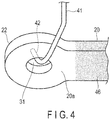
- the powder paint 46 adheres only to the stabilizer body portion 20 at the first thickness as shown in FIG. 4 . Since the powder paint is removed from the eye portion 22, the surface of the steel material 20a is exposed. Although FIG. 4 indicates only the eye portion 22, which is one of the eye portions, the surface of the steel material 20a is also similarly exposed in the other eye portion 21.
- an eye paint spraying step ST4 in FIG. 2B by a paint spraying apparatus 50 shown in FIG. 5 , the powder paint 46 is sprayed toward the eye portions 21 and 22.
- the powder paint 46 adheres to the eye portions 21 and 22 at a second thickness.
- the thickness (second thickness) of the powder paint 46 adhering to the eye portions 21 and 22 is less than the thickness (first thickness) of the powder paint adhering to the stabilizer body portion 20.
- the paint spraying apparatus 50 will be described in detail later.
- a baking step ST5 in FIG. 2B the stabilizer 10 to which the powder paint 46 adheres is accommodated in the heating furnace 44 ( FIG. 2A ), and the paint is baked at a high temperature.
- this baking step ST5 curing reaction occurs in the paint, and a hard coating film which has been smoothed is fixed on the surface of the stabilizer 10.
- Quality of the coated stabilizer 10 is inspected in an inspection step ST6, and an accepted product is completed as a finished product.
- FIG. 5 is a side view showing an example of a usage state of the paint spraying apparatus 50.
- the stabilizer 10 is carried to the paint spraying apparatus 50 in a state in which the eye portion 22 is suspended by the hook 42 of the hanger 41.
- the paint spraying apparatus 50 comprises a supporting structure 51, a lower nozzle unit 60 arranged on the lower part of the supporting structure 51, and an upper nozzle unit 80 provided on the upper part of the supporting structure 51.
- the lower nozzle unit 60 is arranged at a position corresponding to the lower eye portion 21 of the stabilizer 10 which is hung by the hanger 41.
- the upper nozzle unit 80 is arranged at a position corresponding to the upper eye portion 22 of the stabilizer 10 which is hung by the hanger 41.
- the supporting structure 51 includes a pillar portion 52 installed on a floor, etc., in a factory.
- a lower arm portion 53 for the lower nozzle unit 60 is provided on the lower part of the pillar portion 52.
- an upper arm portion 54 for the upper nozzle unit 80 is provided on the upper part of the pillar portion 52.
- the stabilizer 10 in which the eye portion 22 is supported by the hanger 41 is carried in a position inclined obliquely. Accordingly, a distance from the upper eye portion 22 to the pillar portion 52 becomes greater than a distance from the lower eye portion 21 to the pillar portion 52.
- a horizontal length of the lower arm portion 53 is made shorter than a horizontal length of the upper arm portion 54.
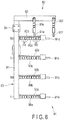
- FIG. 6 is a side view of the lower nozzle unit 60.
- the lower nozzle unit 60 comprises a lower frame 61, lower flexible tubes (tubes with flexibility) 62a to 62f, lower nozzles 65a to 65f, and lower electrodes 66a to 66f.
- the lower frame 61 is supported by the lower arm portion 53.
- the nozzles 65a to 65f are provided at distal ends of the flexible tubes 62a to 62f.
- the lower frame 61 extends substantially vertically and is substantially shaped in the form of the letter I, but may be inclined obliquely.
- the lower frame 61 is not limited to have the I-shaped form.
- the frame shape may be in the form of the letter L, letter T, or letter Y, and each of the nozzles may be arranged at a position suitable for spraying the powder paint 46 toward the lower eye portion 21. Further, the number of nozzles may be other than six.
- the lower flexible tubes 62a to 62f are connected to a paint feed mechanism 71 through a paint feed pipe 70 ( FIG. 5 ).
- the powder paint 46 which is sent with air from the paint feed mechanism 71, is supplied to the lower nozzles 65a to 65f through the flexible tubes 62a to 62f.
- the electrodes 66a to 66f are provided near the nozzles 65a to 65f.
- the electrodes 66a to 66f are arranged adjacent to the nozzles 65a to 65f, respectively.
- the electrodes 66a to 66f are connected to one pole of a high-voltage direct current power supply 75 ( FIG. 5 ).
- the hanger 41 is electrically grounded (earthed) to the other pole of the direct current power supply 75.
- the electrodes 66a to 66f provide a charge to the powder paint 46 ejected from the nozzles 65a to 65f so that the powder paint 46 is electrified with ions.
- Each of the flexible tubes 62a to 62f is constituted by rotatably connecting a plurality of (for example, about 8 to 10) tube elements 63 including a hollow spherical joint, for example, to each other in series. Accordingly, the flexible tubes 62a to 62f can be formed in a bent shape or a straight shape by hand. The shape of the flexible tubes 62a to 62f is maintained by frictional force between the spherical joints of the tube elements 63. Of the six flexible tubes 62a to 62f, four flexible tubes 62a, 62b, 62e, and 62f, for example, are bent toward the lower eye portion 21. The powder paint 46 ejected from each of the lower nozzles 65a, 65b, 65e, and 65f proceeds toward the lower eye portion 21. The lengths of the lower flexible tubes 62a to 62f are equal to each other.
- the powder paint 46 injected toward the lower eye portion 21 adheres to the eye portion 21 by electrostatic force.
- the orientation of the lower nozzles 65a, 65b, 65e, and 65f, and the injection quantity, etc., are set such that the thickness of the powder paint 46 which adheres to the eye portion 21 becomes less than the thickness of the powder paint of the stabilizer body portion 20.
- a quantity of the powder paint 46 ejected from all of the lower nozzles 65a to 65f toward the eye portion 21 is excessive, a part of the nozzles, which are the nozzles 65c and 65d, are treated as dummy nozzles.
- the dummy nozzles 65c and 65d are bent in a direction of avoiding the eye portion 21 so that the powder paint 46 is not discharged toward the eye portion 21.
- a cover such as a bag, may be put on the dummy nozzles 65c and 65d. If the dummy nozzles 65c and 65d are completely closed, a quantity of the powder paint ejected from the other nozzles 65a, 65b, 65e, and 65f is increased. Thus, caution must be taken for this.
- the dummy nozzles 65c and 65d may be directed toward a suction port 101 of a powder recovery apparatus (a dust collector) 100, as shown in FIG. 5 .
- a powder recovery apparatus a dust collector
- the powder paint 46 sprayed out from the dummy nozzles 65c and 65d can be effectively collected.
- all of the lower nozzles 65a to 65f may be directed toward the eye portion 21, so that the powder paint is sprayed from all of the nozzles 65a to 65f toward the eye portion 21.
- FIG. 7 is a side view of the upper nozzle unit 80
- FIG. 8 is a front view of the upper nozzle unit 80.
- the upper nozzle unit 80 is arranged above the lower nozzle unit 60.
- the upper nozzle unit 80 comprises a first frame 81, first flexible tubes (tubes with flexibility) 90a to 90d, a second frame 82, second flexible tubes 90e and 90f, first nozzles 91a to 91d, second nozzles 91e and 91f, and electrodes 92a to 92f.
- the first frame 81 is supported by the upper arm portion 54.
- the first flexible tubes 90a to 90d are arranged on the first frame 81.
- the second frame 82 is provided on the first frame 81.
- the second flexible tubes 90e and 90f are arranged on the second frame 82.
- the nozzles 91a to 91f are provided on distal ends of the flexible tubes 90a to 90f, respectively.
- the number of each of the second flexible tubes and the second nozzles to be provided on the second frame 82 may be other than two.
- a substantially L-shaped upper frame 83 is constituted by the first frame 81 and the second frame 82.
- the first frame 81 and the second frame 82 of the present embodiment are formed of frame members different from each other.
- the first frame 81 and the second frame 82 may be formed integrally by bending a single frame member.
- the first frame 81 extends in a first direction (for example, in a vertical direction).
- the second frame 82 extends in a second direction (for example, a movement direction of the hanger 41) perpendicular to the first frame 81.
- four flexible tubes 90a to 90d are arranged on the first frame 81 at a predetermined pitch.
- the nozzles 91a to 91d are provided on the flexible tubes 90a to 90d, respectively.
- Two flexible tubes 90e and 90f are arranged on the second frame 82.
- the nozzles 91e and 91f are provided on the flexible tubes 90e and 90f, respectively.
- An upper nozzle group 91 is constituted by these nozzles 91a to 91f.
- the shape of the upper frame 83 is not limited to an L-shape, and a T- Y-, or I-shaped frame configuration, for example, may be adopted.
- the respective nozzles are arranged at positions suitable for spraying the powder paint 46 toward the upper eye portion 22.
- the number of nozzles to be arranged at the upper frame 83 may be other than six.
- the flexible tubes 90a to 90f are connected to the paint feed mechanism 71 through the paint feed pipe 70 ( FIG. 5 ).
- the powder paint 46 which is sent with air from the paint feed mechanism 71, is supplied to the nozzles 91a to 91f through the flexible tubes 90a to 90f.
- the electrodes 92a to 92f are provided near the nozzles 91a to 91f.
- the electrodes 92a to 92f are arranged adjacent to the nozzles 91a to 91f, respectively.
- the electrodes 92a to 92f are connected to one pole of the direct current power supply 75 ( FIG. 5 ).
- the electrodes 92a to 92f provide a charge to the powder paint 46 ejected from the nozzles 91a to 91f so that the powder paint 46 is electrified with ions.
- the upper flexible tubes 90a to 90f are constituted by rotatably connecting a plurality of (for example, about 8 to 10) tube elements 63 including a hollow spherical joint to each other in series, likewise the lower flexible tubes 62a to 62f. Accordingly, the flexible tubes 90a to 90f can be formed in a bent shape or a straight shape by hand. The shape of the flexible tubes 90a to 90f is maintained by frictional force between the spherical joints of the tube elements 63.
- Each of the flexible tubes 90a to 90d is bent in a direction corresponding to the upper eye portion 22.
- the nozzles 91a to 91f are provided on distal ends of the flexible tubes 90a to 90f, respectively.
- the powder paint 46 ejected from each of the nozzles 91a to 91f proceeds toward the upper eye portion 22.
- the powder paint 46 injected toward the upper eye portion 22 adheres to the eye portion 22 by electrostatic force.
- the orientation of each of the nozzles 91a to 91f of the upper nozzle unit 80 and the injection quantity, etc., are set such that the thickness (second thickness) of the powder paint 46 which adheres to the eye portion 22 becomes less than the thickness (first thickness) of the powder paint of the stabilizer body portion 20.
- the paint spraying apparatus 50 comprises the powder recovery apparatus 100 (schematically shown in FIG. 5 ).
- the powder paint 46 which did not adhere to the stabilizer 10 of the powder paint 46 ejected from the nozzle groups 65 and 91 is collected by the powder recovery apparatus 100.
- the recovered powder paint 46 is reused (recycled).
- the lower eye portion 21 of the stabilizer 10 suspended from the hanger 41 does not contact the hanger 41. Accordingly, the powder paint 46 can be made to adhere to the lower eye portion 21 by using relatively few (for example, four) nozzles 65a, 65b, 65e, and 65f arranged at the lower frame 61. In contrast, a part of the upper eye portion 22 is in contact with the hanger 41. Moreover, part of the powder paint 46 injected from the upper nozzles 91a to 91f toward the eye portion 22 tends to be attracted to the hanger 41 by electrostatic force. Accordingly, as compared to the lower eye portion 21, the powder paint 46 is hard to be applied to the upper eye portion 22.
- the upper nozzle unit 80 of the present embodiment includes the first frame 81 extending in the first direction (vertical direction), and the second frame 82 extending in the second direction (the movement direction of the hanger 41).
- the nozzles 91a to 91d are arranged at the first frame 81, and the nozzles 91e and 91f are arranged at the second frame 82.
- the upper nozzle unit 80 sprays the powder paint 46 from the six nozzles 91a to 91f toward the eye portion 22.
- the lower nozzle unit 60 sprays the powder paint 46 from the nozzles 65a, 65b, 65e, and 65f fewer than the nozzles of the upper nozzle unit 80 (for example, four in this case) toward the eye portion 21.
- the upper nozzle unit 80 sprays the powder paint 46 toward the eye portion 22 by the nozzles 91a to 91f, the number of which is greater than that of the nozzles of the lower nozzle unit 60. Accordingly, the upper nozzle unit 80 can effectively spray the powder paint 46 aiming at the optimum position of the upper eye portion 22. As a result, the thickness of the coating film being varied in the lower eye portion 21 and the upper eye portion 22 can be avoided, and the coating film of good quality can be formed.
- the stabilizer 10 is carried while being suspended by the hanger 41. Therefore, the lower part of the stabilizer 10, in particular, sways easily. Thus, the position of the lower eye portion 21 becomes more unstable than the upper eye portion 22.
- the position and orientation of the nozzles 65a to 65f are optimized such that the powder paint 46 can be injected in a range wider than a spray range of the nozzle group 91 of the upper nozzle unit 80. By doing so, the powder paint 46 can also be sufficiently sprayed on the lower eye portion 21 which sways easily. Since the upper eye portion 22 does not sway much, the nozzle group 91 of the upper nozzle unit 80 accurately sprays the powder paint 46 in a relatively narrow range aiming at the eye portion 22.
- the upper nozzles 91a to 91f need to be arranged such that the powder paint 46 is injected toward the optimum position of the upper eye portion 22.
- the upper nozzle unit 80 includes the first frame 81 extending in the first direction, and the second frame 82 extending in the second direction perpendicular to the first frame 81.
- a plurality of nozzles 91a to 91f are arranged separately in the first frame 81 and the second frame 82. For this reason, even if the nozzles 91a to 91f are to be arranged to inject the powder paint 46 toward the optimum position of the eye portion 22, the lengths of the respective flexible tubes 90a to 90f can be made equal to each other. Moreover, the lengths of the respective flexible tubes 90a to 90f can be shortened as much as possible.
- the flexible tube comprising a plurality of tube elements 63
- frictional force between the tube elements 63 may be reduced by wear of the spherical joint or degradation over time, for example.
- a distal end side of the long flexible tube may sag under the weight of the nozzle arranged on the distal end.
- relatively short flexible tubes 90a to 90f having a common length can be used, instead of using long flexible tubes. In other words, since use of the long flexible tube can be avoided, a problem that the distal end side of the flexible tube sags under its own weight can be avoided.
- the specific shapes of not only the hanger and the electrostatic gun, which are the constituent elements of the coating installation, but also the supporting structure, the lower nozzle unit, and the upper nozzle unit of the paint spraying apparatus, which constitutes a part of the coating installation may be different from those described in the above embodiment.
- the lower frame of the lower nozzle unit may be structured as a modified frame in the shape of letter L formed by the first frame and the second frame of the upper nozzle unit.
- the lower nozzles may be arranged at the most suitable positions of this modified frame.
- the number and arrangement or the like of the flexible tubes and the nozzles can be modified variously, if needed, when implemented.
Landscapes
- Engineering & Computer Science (AREA)
- Mechanical Engineering (AREA)
- Electrostatic Spraying Apparatus (AREA)
- Application Of Or Painting With Fluid Materials (AREA)
- Vehicle Body Suspensions (AREA)
- Life Sciences & Earth Sciences (AREA)
- Wood Science & Technology (AREA)
Abstract
Description
- The present invention relates to a paint spraying apparatus, a coating installation, and a coating method for use in coating a vehicle stabilizer.
- A stabilizer arranged in a suspension mechanism part of a vehicle, which is formed of a steel pipe or a solid rod-shaped steel material, includes a torsion portion (a twisted portion) which extends in a width direction of the vehicle, and a pair of arm portions (arms) connected via bent portions on both ends of the torsion portion. On a distal end of each of the arm portions, an eye portion is formed. In an example of the suspension mechanism part, the torsion portion of the stabilizer is supported by a vehicle body via a rubber bushing, etc. The eye portion is connected to a suspension arm, etc., via a connecting member such as a stabilizer link. With respect to the stabilizer fitted in the suspension mechanism part, as the arm portion, the bent portion, and the torsion portion function as a spring in reaction to a rolling behavior of the vehicle body, roll stiffness of the vehicle can be enhanced.
- For example, in a hollow stabilizer described in
Patent Literature 1, by flattening both ends of a steel pipe, a pair of eye portions are formed. On the eye portions, flat-shaped fastening surfaces are formed, respectively, and through-holes are formed in the respective fastening surfaces. In each of the through-holes, a connecting member such as a bolt or a stabilizer link is inserted. The eye portion is connected to a suspension mechanism member such as the suspension arm through the connecting member. - Patent Literature 2 describes an example of a method of manufacturing a stabilizer. In this manufacturing method, a coating film is formed on a surface of the stabilizer formed of a steel pipe by a coating process. In one example of the coating process, electrostatic dry spray coating or fluidized bed coating using powder paint is adopted. By the coating process, a coating film is formed on a surface of the steel pipe at a substantially uniform thickness.
- With respect to the coating of the stabilizer, it is required to make the coating film thick in a stabilizer body portion other than the eye portion, and reduce the thickness of the coating film of the eye portion as compared to the stabilizer body portion. In such a case, in a conventional coating method, a paint is sprayed thickly on the entire stabilizer in a state in which the eye portion is subjected to masking, for example. After that, the masking is removed, and the eye portion is coated thinly by touch-up paint. Alternatively, the eye portion may be coated by immersing the eye portion in a dipping tank. In addition, in performing the coating with a coating gun, thinning the coating film of the eye portion by increasing the movement speed of the coating gun at the eye portion as compared to the stabilizer body portion has also been conceived.
-
- Patent Literature 1:
JP H07-237428 A - Patent Literature 2:
JP 2002-331326 A - If the eye portion is to be masked as in the above-mentioned conventional example, it takes time and trouble to provide a masking member on the eye portion before coating, and remove the masking member after the coating. For this reason, a coating method which uses the masking member is not suitable for mass production. In another conventional example, the movement speed of the coating gun is increased at the eye portion, and is decreased in the stabilizer body portion. However, in that case, since the paint is sprayed on the eye portion in a short time, it is difficult to make the paint adhere to the eye portion evenly, and the thickness of the paint may be varied greatly.
- Accordingly, an object of the present invention is to provide a paint spraying apparatus, a coating installation, and a coating method for a stabilizer, which is cable of forming coating films of different thicknesses in the eye portion of the stabilizer and the stabilizer body portion, and reducing variations in the thickness of the coating film of the eye portion.
- A paint spraying apparatus used in a coating installation according to one embodiment includes a supporting structure, a lower nozzle unit provided on the supporting structure and configured to spray powder paint toward a lower eye portion of a stabilizer, and an upper nozzle unit provided on the supporting structure and configured to spray the powder paint toward an upper eye portion of the stabilizer. The lower nozzle unit includes a lower frame, a plurality of lower flexible tubes arranged on the lower frame, lower nozzles provided at respective distal ends of the lower flexible tubes, and configured to eject the powder paint, and lower electrodes which provide a charge to the powder paint ejected from the lower nozzles. The upper nozzle unit comprises a first frame extending in a first direction, a plurality of first flexible tubes arranged on the first frame, first nozzles provided at respective distal ends of the first flexible tubes, and configured to eject the powder paint, a second frame extending in a second direction different from the direction of the first frame, second flexible tubes arranged on the second frame, second nozzles provided at distal ends of the second flexible tubes, and configured to eject the powder paint, upper electrodes which provide a charge to the powder paint ejected from the first nozzles and the second nozzles, and a paint feed mechanism which supplies the powder paint to the lower flexible tubes, the first flexible tubes, and the second flexible tubes.
- A coating installation according to one embodiment includes a hanger including a hook which is inserted into a through-hole of one of eye portions provided on both ends of a stabilizer, an electrostatic gun which sprays charged powder paint on the entire stabilizer suspended by the hanger, thereby making the powder paint adhere to the entire stabilizer at a first thickness, an air injection gun which exfoliates the powder paint adhering to the respective eye portions of the stabilizer by an air blow, the paint spraying apparatus which sprays the powder paint on the respective eye portions, thereby making the powder paint adhere to the eye portions at a second thickness less than the first thickness, and a heating furnace which bakes the powder paint adhering to the stabilizer.
- According to the present invention, it is possible to form coating films of different thicknesses in the eye portion of the stabilizer and the stabilizer body portion, and reduce variations in the thicknesses of the coating films in one eye portion and the other eye portion.
-
-
FIG. 1 is a perspective view showing a part of a vehicle and a stabilizer. -
FIG. 2A is an illustration schematically showing a coating installation according to one embodiment. -
FIG. 2B is a flowchart showing a coating method which uses the coating installation shown inFIG. 2A in the order of steps. -
FIG. 3 is a front view showing an electrostatic gun for spraying powder paint on the entire stabilizer which is supported by a hanger. -
FIG. 4 is a perspective view showing an eye portion of the stabilizer and a part of the hanger shown inFIG. 3 in an enlarged scale. -
FIG. 5 is a side view showing an example of a state of use of a paint spraying apparatus according to one embodiment. -
FIG. 6 is a side view of a lower nozzle unit of the paint spraying apparatus shown inFIG. 5 . -
FIG. 7 is a side view of an upper nozzle unit of the paint spraying apparatus shown inFIG. 5 . -
FIG. 8 is a front view of the upper nozzle unit shown inFIG. 7 . - A coating installation and a coating method for a stabilizer according to one embodiment will be hereinafter described with reference to
FIGS. 1 to 8 . -
FIG. 1 shows a part of avehicle 11 comprising a vehicle stabilizer 10 (which may be simply referred to as a stabilizer in the present specification). Thestabilizer 10 is arranged in a suspension mechanism part provided at the lower part of avehicle body 12. - The
stabilizer 10 includes astabilizer body portion 20 formed of a rod-shaped steel material, and a pair ofeye portions stabilizer body portion 20. Thestabilizer body portion 20 includes atorsion portion 25,bent portions arm portions torsion portion 25 extends in a width direction (i.e., a direction indicated by arrow W inFIG. 1 ) of thevehicle body 12. Thearm portions torsion portion 25 through theircorresponding bent portions stabilizer 10 is substantially bilaterally symmetric when viewed from the front side of thevehicle 11. Accordingly, theeye portions - The shape of the
stabilizer 10 is not limited to planar. For example, thestabilizer 10 may include one or more bending portions in thetorsion portion 25, or one or more bending portions in thearm portions bent portions - The
stabilizer 10 of the present embodiment is a hollow stabilizer. The material of thestabilizer 10 is a hollow steel material (a steel pipe), and is formed into a predetermined shape by a bending machine. An example of the steel material is a type of steel capable of improving its strength by a heat treatment such as quenching, more specifically, using ASB25N or the like as the material. By flattening both ends of the steel material (distal ends of thearm portions 28 and 29) by plastic working (a press), theeye portions - Circular through-
holes eye portions holes eye portions holes members 32 and 33 (FIG. 1 ) such as bolts or stabilizer links are inserted. The connectingmembers eye portions - The
arm portions members torsion portion 25 is supported by a part of the vehicle body 12 (such as a cross-member), for example, via a pair ofsupport portions 34 and 35 (FIG. 1 ) comprising a rubber bushing, etc. When forces having opposite phases are input to thearm portions vehicle 11 drives on a curve, a bending force is exerted on thearm portions bent portions torsion portion 25 is also twisted and a repulsive load is produced. As a result, a rolling behavior of thevehicle body 12 is suppressed. - Coating is applied on a surface of the
stabilizer 10 mainly for rust prevention and also in consideration of appearance quality. For example, in a coating process of thestabilizer 10, powder electrostatic coating (an electrostatic dry spray method) and baking are performed. The thickness of a coating film of theeye portions stabilizer body portion 20 excluding theeye portions eye portions stabilizer body portion 20. -
FIG. 2A schematically shows acoating installation 40 according to one embodiment.FIG. 2B is a flowchart indicating an example of a coating method in the order of steps.FIG. 3 shows a part of thecoating installation 40. Thecoating installation 40 comprises ahanger 41. Thestabilizer 10 is continuously carried in a state in which it is suspended by thehanger 41. Thehanger 41 is made of metal. A plurality ofhangers 41 are provided on amovable body 41a for carrying such as a conveyor chain at a predetermined pitch. Accordingly, the plurality ofstabilizers 10 can be moved simultaneously. - On the lower part of each of the
hangers 41, ahook 42 is provided. The center of gravity G (FIG. 3 ) of thestabilizer 10 is at a position displaced laterally to thetorsion portion 25. Accordingly, when thestabilizer 10 is suspended by inserting thehook 42 into the through-hole 31 of theeye portion 22 on one side, thestabilizer 10 is supported by thehanger 41 in a position inclined obliquely. In other words, thestabilizer 10 is brought to such a state that one of the eye portions, i.e., theeye portion 22, is supported by thehook 42, and the other eye portion, i.e., theeye portion 21, dangles. Further, thestabilizer 10 is continuously moved in a movement path of thecoating installation 40 from a main booth 43 (FIG. 2A ) toward aheating furnace 44. Arrow M inFIG. 2A shows the direction of movement of thestabilizer 10. - An example of the coating process will be explained below with reference to
FIG. 2B . In a preprocessing step ST1 inFIG. 2B , dirt, oil content, etc., on a surface of thestabilizer 10 are removed. As a result, the surface of the stabilizer 10 (the surface of asteel material 20a) is cleaned, and is brought to a state suitable for coating. - In an overall spraying step ST2 in
FIG. 2B , thestabilizer 10 is carried within themain booth 43. Themain booth 43 constitutes a part of thecoating installation 40. In themain booth 43, by powder electrostatic coating which uses a coating robot and an electrostatic gun 45 (FIG. 2A andFIG. 3 ), for example, powder paint is sprayed on the entire surface of thestabilizer 10. - The main ingredients of
powder paint 46 are, for example, paint particles (solid) formed of polymeric resin and a pigment (for example, a black pigment). In the overall spraying step ST2, thepowder paint 46 ejected from theelectrostatic gun 45 is sprayed on theentire stabilizer 10. Thepowder paint 46 ejected from theelectrostatic gun 45 is electrically charged by one of electrodes of a high-voltage direct current power supply. Thestabilizer 10, which is an object to be coated, is formed of thesteel material 20a. Thesteel material 20a is grounded to the other electrode of the direct current power supply. Thepowder paint 46, which is ejected together with air from theelectrostatic gun 45 toward thestabilizer 10, adheres to the entire surface of the stabilizer 10 (thestabilizer body portion 20 and theeye portions 21 and 22) by electrostatic force at a first thickness. - The
stabilizer 10 to which thepowder paint 46 has adhered is introduced in anair blow chamber 48 in an air blow step ST3 inFIG. 2B . Theair blow chamber 48 constitutes a part of thecoating installation 40. Inside theair blow chamber 48, air is sprayed on theeye portions FIG. 3 ). By this air blow process, the powder paint which had been adhered to theeye portions eye portions - On the surface of the
stabilizer 10 which has underwent the air blow step ST3, thepowder paint 46 adheres only to thestabilizer body portion 20 at the first thickness as shown inFIG. 4 . Since the powder paint is removed from theeye portion 22, the surface of thesteel material 20a is exposed. AlthoughFIG. 4 indicates only theeye portion 22, which is one of the eye portions, the surface of thesteel material 20a is also similarly exposed in theother eye portion 21. - In an eye paint spraying step ST4 in
FIG. 2B , by apaint spraying apparatus 50 shown inFIG. 5 , thepowder paint 46 is sprayed toward theeye portions powder paint 46 adheres to theeye portions powder paint 46 adhering to theeye portions stabilizer body portion 20. Thepaint spraying apparatus 50 will be described in detail later. - In a baking step ST5 in
FIG. 2B , thestabilizer 10 to which thepowder paint 46 adheres is accommodated in the heating furnace 44 (FIG. 2A ), and the paint is baked at a high temperature. By undergoing this baking step ST5, curing reaction occurs in the paint, and a hard coating film which has been smoothed is fixed on the surface of thestabilizer 10. Quality of thecoated stabilizer 10 is inspected in an inspection step ST6, and an accepted product is completed as a finished product. - Next, with reference to
FIGS. 5 to 8 , an embodiment of thepaint spraying apparatus 50 will be described. Thepaint spraying apparatus 50 constitutes a part of thecoating installation 40.FIG. 5 is a side view showing an example of a usage state of thepaint spraying apparatus 50. Thestabilizer 10 is carried to thepaint spraying apparatus 50 in a state in which theeye portion 22 is suspended by thehook 42 of thehanger 41. - The
paint spraying apparatus 50 comprises a supportingstructure 51, alower nozzle unit 60 arranged on the lower part of the supportingstructure 51, and anupper nozzle unit 80 provided on the upper part of the supportingstructure 51. Thelower nozzle unit 60 is arranged at a position corresponding to thelower eye portion 21 of thestabilizer 10 which is hung by thehanger 41. Theupper nozzle unit 80 is arranged at a position corresponding to theupper eye portion 22 of thestabilizer 10 which is hung by thehanger 41. - The supporting
structure 51 includes apillar portion 52 installed on a floor, etc., in a factory. Alower arm portion 53 for thelower nozzle unit 60 is provided on the lower part of thepillar portion 52. On the upper part of thepillar portion 52, anupper arm portion 54 for theupper nozzle unit 80 is provided. As shown inFIG. 5 , thestabilizer 10 in which theeye portion 22 is supported by thehanger 41 is carried in a position inclined obliquely. Accordingly, a distance from theupper eye portion 22 to thepillar portion 52 becomes greater than a distance from thelower eye portion 21 to thepillar portion 52. Thus, in a case of an embodiment shown inFIG. 5 , a horizontal length of thelower arm portion 53 is made shorter than a horizontal length of theupper arm portion 54. -
FIG. 6 is a side view of thelower nozzle unit 60. Thelower nozzle unit 60 comprises alower frame 61, lower flexible tubes (tubes with flexibility) 62a to 62f,lower nozzles 65a to 65f, andlower electrodes 66a to 66f. Thelower frame 61 is supported by thelower arm portion 53. Thenozzles 65a to 65f are provided at distal ends of theflexible tubes 62a to 62f. Thelower frame 61 extends substantially vertically and is substantially shaped in the form of the letter I, but may be inclined obliquely. - In the case of the present embodiment, as an example, six
flexible tubes 62a to 62f andnozzles 65a to 65f are arranged in line at a predetermined pitch on thelower frame 61. Thesenozzles 65a to 65f constitute alower nozzle group 65. Note that thelower frame 61 is not limited to have the I-shaped form. For example, the frame shape may be in the form of the letter L, letter T, or letter Y, and each of the nozzles may be arranged at a position suitable for spraying thepowder paint 46 toward thelower eye portion 21. Further, the number of nozzles may be other than six. - The lower
flexible tubes 62a to 62f are connected to apaint feed mechanism 71 through a paint feed pipe 70 (FIG. 5 ). Thepowder paint 46, which is sent with air from thepaint feed mechanism 71, is supplied to thelower nozzles 65a to 65f through theflexible tubes 62a to 62f. - The
electrodes 66a to 66f are provided near thenozzles 65a to 65f. For example, theelectrodes 66a to 66f are arranged adjacent to thenozzles 65a to 65f, respectively. Theelectrodes 66a to 66f are connected to one pole of a high-voltage direct current power supply 75 (FIG. 5 ). Thehanger 41 is electrically grounded (earthed) to the other pole of the directcurrent power supply 75. Theelectrodes 66a to 66f provide a charge to thepowder paint 46 ejected from thenozzles 65a to 65f so that thepowder paint 46 is electrified with ions. - Each of the
flexible tubes 62a to 62f is constituted by rotatably connecting a plurality of (for example, about 8 to 10)tube elements 63 including a hollow spherical joint, for example, to each other in series. Accordingly, theflexible tubes 62a to 62f can be formed in a bent shape or a straight shape by hand. The shape of theflexible tubes 62a to 62f is maintained by frictional force between the spherical joints of thetube elements 63. Of the sixflexible tubes 62a to 62f, fourflexible tubes lower eye portion 21. Thepowder paint 46 ejected from each of thelower nozzles lower eye portion 21. The lengths of the lowerflexible tubes 62a to 62f are equal to each other. - The
powder paint 46 injected toward thelower eye portion 21 adheres to theeye portion 21 by electrostatic force. The orientation of thelower nozzles powder paint 46 which adheres to theeye portion 21 becomes less than the thickness of the powder paint of thestabilizer body portion 20. - If a quantity of the
powder paint 46 ejected from all of thelower nozzles 65a to 65f toward theeye portion 21 is excessive, a part of the nozzles, which are thenozzles eye portion 21 so that thepowder paint 46 is not discharged toward theeye portion 21. Alternatively, a cover, such as a bag, may be put on thedummy nozzles dummy nozzles other nozzles - The dummy nozzles 65c and 65d may be directed toward a
suction port 101 of a powder recovery apparatus (a dust collector) 100, as shown inFIG. 5 . By doing so, thepowder paint 46 sprayed out from thedummy nozzles eye portion 21, all of thelower nozzles 65a to 65f may be directed toward theeye portion 21, so that the powder paint is sprayed from all of thenozzles 65a to 65f toward theeye portion 21. -
FIG. 7 is a side view of theupper nozzle unit 80, andFIG. 8 is a front view of theupper nozzle unit 80. Theupper nozzle unit 80 is arranged above thelower nozzle unit 60. Theupper nozzle unit 80 comprises afirst frame 81, first flexible tubes (tubes with flexibility) 90a to 90d, asecond frame 82, secondflexible tubes first nozzles 91a to 91d,second nozzles electrodes 92a to 92f. Thefirst frame 81 is supported by theupper arm portion 54. The firstflexible tubes 90a to 90d are arranged on thefirst frame 81. Thesecond frame 82 is provided on thefirst frame 81. The secondflexible tubes second frame 82. Thenozzles 91a to 91f are provided on distal ends of theflexible tubes 90a to 90f, respectively. The number of each of the second flexible tubes and the second nozzles to be provided on thesecond frame 82 may be other than two. - A substantially L-shaped
upper frame 83 is constituted by thefirst frame 81 and thesecond frame 82. Thefirst frame 81 and thesecond frame 82 of the present embodiment are formed of frame members different from each other. However, as another form of theupper frame 83, thefirst frame 81 and thesecond frame 82 may be formed integrally by bending a single frame member. - The
first frame 81 extends in a first direction (for example, in a vertical direction). Thesecond frame 82 extends in a second direction (for example, a movement direction of the hanger 41) perpendicular to thefirst frame 81. As an example, fourflexible tubes 90a to 90d are arranged on thefirst frame 81 at a predetermined pitch. Thenozzles 91a to 91d are provided on theflexible tubes 90a to 90d, respectively. Twoflexible tubes second frame 82. Thenozzles flexible tubes upper nozzle group 91 is constituted by thesenozzles 91a to 91f. - Note that the shape of the
upper frame 83 is not limited to an L-shape, and a T- Y-, or I-shaped frame configuration, for example, may be adopted. In theupper frame 83, the respective nozzles are arranged at positions suitable for spraying thepowder paint 46 toward theupper eye portion 22. The number of nozzles to be arranged at theupper frame 83 may be other than six. - The
flexible tubes 90a to 90f are connected to thepaint feed mechanism 71 through the paint feed pipe 70 (FIG. 5 ). Thepowder paint 46, which is sent with air from thepaint feed mechanism 71, is supplied to thenozzles 91a to 91f through theflexible tubes 90a to 90f. - The
electrodes 92a to 92f are provided near thenozzles 91a to 91f. For example, theelectrodes 92a to 92f are arranged adjacent to thenozzles 91a to 91f, respectively. Theelectrodes 92a to 92f are connected to one pole of the direct current power supply 75 (FIG. 5 ). Theelectrodes 92a to 92f provide a charge to thepowder paint 46 ejected from thenozzles 91a to 91f so that thepowder paint 46 is electrified with ions. - The upper
flexible tubes 90a to 90f are constituted by rotatably connecting a plurality of (for example, about 8 to 10)tube elements 63 including a hollow spherical joint to each other in series, likewise the lowerflexible tubes 62a to 62f. Accordingly, theflexible tubes 90a to 90f can be formed in a bent shape or a straight shape by hand. The shape of theflexible tubes 90a to 90f is maintained by frictional force between the spherical joints of thetube elements 63. - Four
flexible tubes 90a to 90d are arranged on thefirst frame 81. Twoflexible tubes second frame 82. Each of theflexible tubes 90a to 90f is bent in a direction corresponding to theupper eye portion 22. Thenozzles 91a to 91f are provided on distal ends of theflexible tubes 90a to 90f, respectively. Thepowder paint 46 ejected from each of thenozzles 91a to 91f proceeds toward theupper eye portion 22. - The
powder paint 46 injected toward theupper eye portion 22 adheres to theeye portion 22 by electrostatic force. The orientation of each of thenozzles 91a to 91f of theupper nozzle unit 80 and the injection quantity, etc., are set such that the thickness (second thickness) of thepowder paint 46 which adheres to theeye portion 22 becomes less than the thickness (first thickness) of the powder paint of thestabilizer body portion 20. - The
paint spraying apparatus 50 comprises the powder recovery apparatus 100 (schematically shown inFIG. 5 ). Thepowder paint 46 which did not adhere to thestabilizer 10 of thepowder paint 46 ejected from thenozzle groups powder recovery apparatus 100. The recoveredpowder paint 46 is reused (recycled). - The
lower eye portion 21 of thestabilizer 10 suspended from thehanger 41 does not contact thehanger 41. Accordingly, thepowder paint 46 can be made to adhere to thelower eye portion 21 by using relatively few (for example, four)nozzles lower frame 61. In contrast, a part of theupper eye portion 22 is in contact with thehanger 41. Moreover, part of thepowder paint 46 injected from theupper nozzles 91a to 91f toward theeye portion 22 tends to be attracted to thehanger 41 by electrostatic force. Accordingly, as compared to thelower eye portion 21, thepowder paint 46 is hard to be applied to theupper eye portion 22. - The
upper nozzle unit 80 of the present embodiment includes thefirst frame 81 extending in the first direction (vertical direction), and thesecond frame 82 extending in the second direction (the movement direction of the hanger 41). Thenozzles 91a to 91d are arranged at thefirst frame 81, and thenozzles second frame 82. Further, theupper nozzle unit 80 sprays thepowder paint 46 from the sixnozzles 91a to 91f toward theeye portion 22. In contrast, thelower nozzle unit 60 sprays thepowder paint 46 from thenozzles eye portion 21. As described above, theupper nozzle unit 80 sprays thepowder paint 46 toward theeye portion 22 by thenozzles 91a to 91f, the number of which is greater than that of the nozzles of thelower nozzle unit 60. Accordingly, theupper nozzle unit 80 can effectively spray thepowder paint 46 aiming at the optimum position of theupper eye portion 22. As a result, the thickness of the coating film being varied in thelower eye portion 21 and theupper eye portion 22 can be avoided, and the coating film of good quality can be formed. - The
stabilizer 10 is carried while being suspended by thehanger 41. Therefore, the lower part of thestabilizer 10, in particular, sways easily. Thus, the position of thelower eye portion 21 becomes more unstable than theupper eye portion 22. In consideration of the above, in thenozzle group 65 of thelower nozzle unit 60, the position and orientation of thenozzles 65a to 65f are optimized such that thepowder paint 46 can be injected in a range wider than a spray range of thenozzle group 91 of theupper nozzle unit 80. By doing so, thepowder paint 46 can also be sufficiently sprayed on thelower eye portion 21 which sways easily. Since theupper eye portion 22 does not sway much, thenozzle group 91 of theupper nozzle unit 80 accurately sprays thepowder paint 46 in a relatively narrow range aiming at theeye portion 22. - The
upper nozzles 91a to 91f need to be arranged such that thepowder paint 46 is injected toward the optimum position of theupper eye portion 22. Theupper nozzle unit 80 includes thefirst frame 81 extending in the first direction, and thesecond frame 82 extending in the second direction perpendicular to thefirst frame 81. A plurality ofnozzles 91a to 91f are arranged separately in thefirst frame 81 and thesecond frame 82. For this reason, even if thenozzles 91a to 91f are to be arranged to inject thepowder paint 46 toward the optimum position of theeye portion 22, the lengths of the respectiveflexible tubes 90a to 90f can be made equal to each other. Moreover, the lengths of the respectiveflexible tubes 90a to 90f can be shortened as much as possible. - With respect to the flexible tube comprising a plurality of
tube elements 63, frictional force between thetube elements 63 may be reduced by wear of the spherical joint or degradation over time, for example. When a long flexible tube is used, a distal end side of the long flexible tube may sag under the weight of the nozzle arranged on the distal end. In contrast, for thenozzle unit 80 of the present embodiment, relatively shortflexible tubes 90a to 90f having a common length can be used, instead of using long flexible tubes. In other words, since use of the long flexible tube can be avoided, a problem that the distal end side of the flexible tube sags under its own weight can be avoided. - In carrying out the present invention, the specific shapes of not only the hanger and the electrostatic gun, which are the constituent elements of the coating installation, but also the supporting structure, the lower nozzle unit, and the upper nozzle unit of the paint spraying apparatus, which constitutes a part of the coating installation, may be different from those described in the above embodiment. For example, the lower frame of the lower nozzle unit may be structured as a modified frame in the shape of letter L formed by the first frame and the second frame of the upper nozzle unit. Further, the lower nozzles may be arranged at the most suitable positions of this modified frame. Needless to say, the number and arrangement or the like of the flexible tubes and the nozzles can be modified variously, if needed, when implemented.
- 10 ···Stabilizer, 20 ···Stabilizer body portion, 21, 22 ···Eye portions, 30, 31 ···Through-holes, 40 ···Coating installation, 41 ···Hanger, 42 ···Hook, 44 ···Heating furnace, 45 ···Electrostatic gun, 46 ···Powder paint, 47 ···injection gun, 50 ···Paint spraying apparatus, 51 ···Supporting structure, 60 ···Lower nozzle unit, 61 ···Lower frame, 62a-62f ···Lower flexible tubes, 63 ···Tube element, 65 ···Lower nozzle group, 65a-65f ···Lower nozzles, 66a-66f ···Electrodes, 70 ···Paint feed pipe, 71 ···Paint feed mechanism, 75 ···Direct current power supply, 80 ···Upper nozzle unit, 81 ···First frame, 82 ···Second frame, 83 ···Upper frame, 90a-90d ···First flexible tubes, 90e, 90f ···Second flexible tubes, 91 ···Nozzle group, 91a-91d ···First nozzles, 91e, 91f ···Second nozzles, 92a-92f ···Electrodes
Claims (7)
- A paint spraying apparatus for a stabilizer characterized by comprising:a supporting structure (51);a lower nozzle unit (60) provided on the supporting structure (51) and configured to spray powder paint (46) toward a lower eye portion (21) of the stabilizer (10); andan upper nozzle unit (80) provided on the supporting structure (51) and configured to spray the powder paint (46) toward an upper eye portion (22) of the stabilizer (10),wherein the lower nozzle unit (60) comprises:a lower frame (61);a plurality of lower flexible tubes (62a-62f) arranged on the lower frame (61);lower nozzles (65a-65f) provided at respective distal ends of the lower flexible tubes (62a-62f), and configured to eject the powder paint (46); andlower electrodes (66a-66f) which provide a charge to the powder paint (46) ejected from the lower nozzles (65a-65f), andthe upper nozzle unit (80) comprises:a first frame (81) extending in a first direction;a plurality of first flexible tubes (90a-90d) arranged on the first frame (81);first nozzles (91a-91d) provided at respective distal ends of the first flexible tubes (90a-90d), and configured to eject the powder paint (46);a second frame (82) extending in a second direction different from the direction of the first frame (81);second flexible tubes (90e,90f) arranged on the second frame (82);second nozzles (91e,91f) provided at distal ends of the second flexible tubes (90e,90f), and configured to eject the powder paint (46);upper electrodes (92a-92f) which provide a charge to the powder paint (46) ejected from the first nozzles (91a-91d) and the second nozzles (91e,91f); anda paint feed mechanism (71) which supplies the powder paint (46) to the lower flexible tubes (62a-62f), the first flexible tubes (90a-90d), and the second flexible tubes (90e,90f).
- The paint spraying apparatus of Claim 1, characterized in that each of the lower flexible tubes (62a-62f) is constituted by connecting a plurality of tube elements (63) to each other in series, the tube elements (63) having shapes in common with each other with a hollow spherical joint, and lengths of the lower flexible tubes (62a-62f) are equal to each other.
- The paint spraying apparatus of Claim 1 or 2, characterized in that each of the first flexible tubes (90a-90d) and the second flexible tubes (90e,90f) is constituted by connecting a plurality of tube elements (63) to each other in series, the tube elements (63) having shapes in common with each other with a hollow spherical joint, and lengths of the first flexible tubes (90a-90d) and the second flexible tubes (90e,90f) are equal to each other.
- The paint spraying apparatus of Claim 1 or 2, characterized in that part of the lower nozzles (65a-65f) are dummy nozzles (65c,65d), and the dummy nozzles (65c,65d) inject the powder paint (46) in a direction of avoiding the lower eye portion (21).
- The paint spraying apparatus of Claim 4, characterized in that the dummy nozzles (65c,65d) are directed toward a powder recovery apparatus (100).
- A coating installation (40) characterized by comprising:a hanger (41) including a hook (42) which is inserted into a through-hole (31) of one eye portion (22) of eye portions (21)(22) provided on both ends of a stabilizer (10);an electrostatic gun (45) which sprays charged powder paint (46) on a whole of the stabilizer (10) suspended by the hanger (41), thereby making the powder paint (46) adhere to the whole of the stabilizer (10) at a first thickness;an air injection gun (47) which exfoliates the powder paint (46) adhering to the respective eye portions (21)(22) of the stabilizer (10) by an air blow;a paint spraying apparatus (50) which sprays the powder paint (46) on the respective eye portions (21)(22), thereby making the powder paint (46) adhere to the eye portions (21)(22) at a second thickness less than the first thickness; anda heating furnace (44) which bakes the powder paint (46) adhering to the stabilizer (10),wherein the paint spraying apparatus (50) comprises:a supporting structure (51);a lower nozzle unit (60) provided on the supporting structure (51) and configured to spray the powder paint (46) toward the eye portion (21) on a lower side of the stabilizer (10); andan upper nozzle unit (80) provided on the supporting structure (51) and configured to spray the powder paint (46) toward the eye portion (22) on an upper side of the stabilizer (10),the lower nozzle unit (60) comprises:a lower frame (61);a plurality of lower flexible tubes (62a-62f) arranged on the lower frame (61);lower nozzles (65a-65f) provided at respective distal ends of the lower flexible tubes (62a-62f), and configured to eject the powder paint (46); andlower electrodes (66a-66f) which provide a charge to the powder paint (46) ejected from the lower nozzles (65a-65f), andthe upper nozzle unit (80) comprises:a first frame (81) extending in a first direction;a plurality of first flexible tubes (90a-90d) arranged on the first frame (81);first nozzles (91a-91d) provided at respective distal ends of the first flexible tubes (90a-90d), and configured to eject the powder paint (46);a second frame (82) extending in a second direction different from the direction of the first frame (81);second flexible tubes (90e,90f) arranged on the second frame (82);second nozzles (91e,91f) provided at distal ends of the second flexible tubes (90e,90f), and configured to eject the powder paint (46);upper electrodes (92a-92f) which provide a charge to the powder paint (46) ejected from the first nozzles (91a-91d) and the second nozzles (91e,91f); anda paint feed mechanism (71) which supplies the powder paint (46) to the lower flexible tubes (62a-62f), the first flexible tubes (90a-90d), and the second flexible tubes (90e,90f).
- A coating method characterized by comprising:carrying a stabilizer (10) in a suspended state by hanging one eye portion (22) of eye portions (21)(22) on both ends of the stabilizer (10) on a hook (42) of a hanger (41);spraying charged powder paint (46) on a whole of the stabilizer (10) suspended by the hanger (41), thereby making the powder paint (46) adhere to the whole of the stabilizer (10) at a first thickness;exfoliating the powder paint (46) adhering to the eye portions (21)(22) by an air blow;spraying the powder paint (46) toward the eye portion (21) on a lower side by lower nozzles (65a-65f) arranged at positions corresponding to the lower eye portion (21) of the stabilizer (10), thereby making the powder paint (46) adhere to the lower eye portion (21) at a second thickness less than the first thickness;spraying the powder paint (46) toward the eye portion (22) on an upper side by upper nozzles (91a-91f) arranged at positions corresponding to the upper eye portion (22) of the stabilizer (10), thereby making the powder paint (46) adhere to the upper eye portion (22) at the second thickness; andheating the powder paint (46) adhering to the stabilizer (10) and baking the powder paint (46) on a surface of the stabilizer (10).
Applications Claiming Priority (2)
| Application Number | Priority Date | Filing Date | Title |
|---|---|---|---|
| JP2015209163 | 2015-10-23 | ||
| PCT/JP2016/080140 WO2017069018A1 (en) | 2015-10-23 | 2016-10-11 | Coating spraying device for stabilizer, coating equipment, and coating method |
Publications (3)
| Publication Number | Publication Date |
|---|---|
| EP3366378A1 true EP3366378A1 (en) | 2018-08-29 |
| EP3366378A4 EP3366378A4 (en) | 2019-05-15 |
| EP3366378B1 EP3366378B1 (en) | 2020-08-26 |
Family
ID=58558021
Family Applications (1)
| Application Number | Title | Priority Date | Filing Date |
|---|---|---|---|
| EP16857333.5A Active EP3366378B1 (en) | 2015-10-23 | 2016-10-11 | Coating spraying device for stabilizer, coating equipment, and coating method |
Country Status (7)
| Country | Link |
|---|---|
| US (1) | US10792683B2 (en) |
| EP (1) | EP3366378B1 (en) |
| JP (1) | JP6431616B2 (en) |
| CN (1) | CN108136421B (en) |
| ES (1) | ES2821105T3 (en) |
| HU (1) | HUE051874T2 (en) |
| WO (1) | WO2017069018A1 (en) |
Families Citing this family (6)
| Publication number | Priority date | Publication date | Assignee | Title |
|---|---|---|---|---|
| EP3357724B1 (en) * | 2015-10-02 | 2020-08-26 | NHK Spring Co., Ltd. | Stabilizer for vehicle |
| CN109718957A (en) * | 2018-11-30 | 2019-05-07 | 天津市大港汽车配件弹簧厂 | The virtual hanging point coating process of automobile stabilizer bar |
| JP7233227B2 (en) * | 2019-01-17 | 2023-03-06 | ソマール株式会社 | Coating gun and powder coating equipment |
| KR101994073B1 (en) * | 2019-03-13 | 2019-06-27 | 조현호 | Jigs for surface treatment of steering linkage equipment for vehicles |
| DE102019122918A1 (en) * | 2019-08-27 | 2021-03-04 | Dürr Systems Ag | Applicator for applying a sealing compound to a flange fold |
| FR3117910B1 (en) * | 2020-12-18 | 2023-04-07 | Exel Ind | Electrostatic powder coating robot, system and method |
Family Cites Families (14)
| Publication number | Priority date | Publication date | Assignee | Title |
|---|---|---|---|---|
| FR2028690A1 (en) * | 1969-01-23 | 1970-10-16 | Kh Vagonoremontn | |
| JP3489035B2 (en) * | 1993-04-07 | 2004-01-19 | ノードソン株式会社 | Powder coating equipment |
| JP3168236B2 (en) * | 1994-02-28 | 2001-05-21 | 日本発条株式会社 | Hollow stabilizer for vehicles and method of manufacturing the same |
| JP2002331326A (en) * | 2001-03-08 | 2002-11-19 | Nhk Spring Co Ltd | Hollow stabilizer and method of manufacturing the same |
| DE10319916A1 (en) * | 2003-05-05 | 2004-11-25 | Itw Gema Ag | Spraying device for coating material, in particular coating powder |
| EP2368641A4 (en) * | 2008-12-24 | 2012-05-02 | Honda Motor Co Ltd | Powder coating device and powder coating method |
| JP5420307B2 (en) * | 2008-12-24 | 2014-02-19 | 本田技研工業株式会社 | Powder coating equipment |
| CN102189910B (en) * | 2010-03-19 | 2013-02-27 | 上海中国弹簧制造有限公司 | Manufacturing process of hollow stabilizer rod of automobile |
| JP5606807B2 (en) | 2010-06-14 | 2014-10-15 | 中央発條株式会社 | Powder coating method |
| CN102129910B (en) * | 2010-12-24 | 2012-12-05 | 珠海格力新元电子有限公司 | Process method for reducing noise of film capacitor |
| DE102011055980B4 (en) * | 2011-12-02 | 2014-10-16 | Benteler Automobiltechnik Gmbh | Process for coating metal components and plant for carrying out the process |
| JP2013136022A (en) * | 2011-12-28 | 2013-07-11 | Chuo Spring Co Ltd | Method for coating spring member |
| JP2014018727A (en) * | 2012-07-17 | 2014-02-03 | Chuo Spring Co Ltd | Spring member |
| JP6110840B2 (en) * | 2014-12-08 | 2017-04-05 | 日本発條株式会社 | Stabilizer manufacturing method |
-
2016
- 2016-10-11 ES ES16857333T patent/ES2821105T3/en active Active
- 2016-10-11 EP EP16857333.5A patent/EP3366378B1/en active Active
- 2016-10-11 HU HUE16857333A patent/HUE051874T2/en unknown
- 2016-10-11 WO PCT/JP2016/080140 patent/WO2017069018A1/en not_active Ceased
- 2016-10-11 CN CN201680060828.3A patent/CN108136421B/en active Active
- 2016-10-11 JP JP2017546507A patent/JP6431616B2/en active Active
-
2018
- 2018-04-17 US US15/954,871 patent/US10792683B2/en active Active
Also Published As
| Publication number | Publication date |
|---|---|
| US20180229250A1 (en) | 2018-08-16 |
| EP3366378A4 (en) | 2019-05-15 |
| US10792683B2 (en) | 2020-10-06 |
| WO2017069018A1 (en) | 2017-04-27 |
| HUE051874T2 (en) | 2021-03-29 |
| CN108136421B (en) | 2020-04-07 |
| JPWO2017069018A1 (en) | 2018-04-05 |
| JP6431616B2 (en) | 2018-11-28 |
| EP3366378B1 (en) | 2020-08-26 |
| ES2821105T3 (en) | 2021-04-23 |
| CN108136421A (en) | 2018-06-08 |
Similar Documents
| Publication | Publication Date | Title |
|---|---|---|
| US10792683B2 (en) | Paint spraying apparatus for stabilizer, coating installation, and coating method | |
| CA2670237C (en) | Workpiece carrier for conveying a workpiece to be painted | |
| EP1745858A2 (en) | Coating process and corresponding apparatus | |
| US20120231174A1 (en) | Device and method for applying paints | |
| US10589590B2 (en) | Stabilizer for vehicle | |
| CN103826755A (en) | Coating method and coating device for compensating spray asymmetry | |
| JP2008049281A (en) | Powder coat deposition system and powder coat deposition method | |
| CN110026506A (en) | A kind of spring production process | |
| JP5352799B2 (en) | Corona charging device | |
| US20080169172A1 (en) | Surface Treating Installation Comprising A Transfer Station | |
| JPS6028852A (en) | Painting device | |
| CH491679A (en) | Process for coating hollow bodies | |
| CN204490731U (en) | A kind of automobile rearview mirror spray equipment | |
| CN223931718U (en) | Steel pipe inner wall anticorrosive coating device | |
| CN216459562U (en) | Spraying line hangs direction conveying system | |
| KR102907803B1 (en) | Manufacturing apparatus and method of tinted stainless steeel using plasma process | |
| ITVI20080134A1 (en) | SUPPORT DEVICE FOR SPRAY PAINTING OF METAL PRODUCTS AND RELATIVE PAINTING PROCEDURE. | |
| CN215141074U (en) | Automatic electrostatic spraying equipment | |
| CN214390781U (en) | Guide rail assembly and powder spraying device | |
| JPH0857361A (en) | Electrostatic powder coating method and apparatus | |
| SU749438A1 (en) | Plant for applying polymer coatings | |
| DE2650337A1 (en) | Electrostatic dip tank powder coating - has jet appts. with suction opening in fluidised powder bed | |
| JPH0413028B2 (en) | ||
| WO2019202701A1 (en) | Electrostatic coating device for resin molded articles and electrostatic coating method for resin molded articles | |
| JPH0675693B2 (en) | Vehicle electrostatic coating line |
Legal Events
| Date | Code | Title | Description |
|---|---|---|---|
| STAA | Information on the status of an ep patent application or granted ep patent |
Free format text: STATUS: THE INTERNATIONAL PUBLICATION HAS BEEN MADE |
|
| PUAI | Public reference made under article 153(3) epc to a published international application that has entered the european phase |
Free format text: ORIGINAL CODE: 0009012 |
|
| STAA | Information on the status of an ep patent application or granted ep patent |
Free format text: STATUS: REQUEST FOR EXAMINATION WAS MADE |
|
| 17P | Request for examination filed |
Effective date: 20180418 |
|
| AK | Designated contracting states |
Kind code of ref document: A1 Designated state(s): AL AT BE BG CH CY CZ DE DK EE ES FI FR GB GR HR HU IE IS IT LI LT LU LV MC MK MT NL NO PL PT RO RS SE SI SK SM TR |
|
| AX | Request for extension of the european patent |
Extension state: BA ME |
|
| DAV | Request for validation of the european patent (deleted) | ||
| DAX | Request for extension of the european patent (deleted) | ||
| A4 | Supplementary search report drawn up and despatched |
Effective date: 20190416 |
|
| RIC1 | Information provided on ipc code assigned before grant |
Ipc: B05B 12/18 20180101ALI20190410BHEP Ipc: B05D 7/24 20060101ALI20190410BHEP Ipc: B05B 5/043 20060101ALN20190410BHEP Ipc: B05B 5/08 20060101AFI20190410BHEP Ipc: B05D 1/06 20060101ALI20190410BHEP Ipc: B05B 5/025 20060101ALI20190410BHEP Ipc: B05D 3/02 20060101ALI20190410BHEP Ipc: B05B 7/14 20060101ALN20190410BHEP Ipc: B05B 13/02 20060101ALI20190410BHEP Ipc: B05D 7/14 20060101ALI20190410BHEP Ipc: B60G 21/055 20060101ALI20190410BHEP |
|
| GRAP | Despatch of communication of intention to grant a patent |
Free format text: ORIGINAL CODE: EPIDOSNIGR1 |
|
| STAA | Information on the status of an ep patent application or granted ep patent |
Free format text: STATUS: GRANT OF PATENT IS INTENDED |
|
| RIC1 | Information provided on ipc code assigned before grant |
Ipc: B05B 7/14 20060101ALN20200227BHEP Ipc: B05D 3/02 20060101ALI20200227BHEP Ipc: B05B 5/043 20060101ALN20200227BHEP Ipc: B05D 1/06 20060101ALI20200227BHEP Ipc: B05D 7/14 20060101ALI20200227BHEP Ipc: B05D 7/24 20060101ALI20200227BHEP Ipc: B05B 5/025 20060101ALI20200227BHEP Ipc: B60G 21/055 20060101ALI20200227BHEP Ipc: B05B 12/18 20180101ALI20200227BHEP Ipc: B05B 5/08 20060101AFI20200227BHEP Ipc: B05D 3/04 20060101ALN20200227BHEP Ipc: B05B 13/02 20060101ALI20200227BHEP |
|
| RIC1 | Information provided on ipc code assigned before grant |
Ipc: B05D 3/02 20060101ALI20200305BHEP Ipc: B05B 7/14 20060101ALN20200305BHEP Ipc: B05D 7/14 20060101ALI20200305BHEP Ipc: B05B 13/02 20060101ALI20200305BHEP Ipc: B05B 5/043 20060101ALN20200305BHEP Ipc: B05D 7/24 20060101ALI20200305BHEP Ipc: B05D 3/04 20060101ALN20200305BHEP Ipc: B05D 1/06 20060101ALI20200305BHEP Ipc: B60G 21/055 20060101ALI20200305BHEP Ipc: B05B 12/18 20180101ALI20200305BHEP Ipc: B05B 5/025 20060101ALI20200305BHEP Ipc: B05B 5/08 20060101AFI20200305BHEP |
|
| INTG | Intention to grant announced |
Effective date: 20200323 |
|
| GRAS | Grant fee paid |
Free format text: ORIGINAL CODE: EPIDOSNIGR3 |
|
| GRAA | (expected) grant |
Free format text: ORIGINAL CODE: 0009210 |
|
| STAA | Information on the status of an ep patent application or granted ep patent |
Free format text: STATUS: THE PATENT HAS BEEN GRANTED |
|
| AK | Designated contracting states |
Kind code of ref document: B1 Designated state(s): AL AT BE BG CH CY CZ DE DK EE ES FI FR GB GR HR HU IE IS IT LI LT LU LV MC MK MT NL NO PL PT RO RS SE SI SK SM TR |
|
| REG | Reference to a national code |
Ref country code: GB Ref legal event code: FG4D |
|
| REG | Reference to a national code |
Ref country code: CH Ref legal event code: EP |
|
| REG | Reference to a national code |
Ref country code: AT Ref legal event code: REF Ref document number: 1305858 Country of ref document: AT Kind code of ref document: T Effective date: 20200915 |
|
| REG | Reference to a national code |
Ref country code: IE Ref legal event code: FG4D |
|
| REG | Reference to a national code |
Ref country code: DE Ref legal event code: R096 Ref document number: 602016042938 Country of ref document: DE |
|
| REG | Reference to a national code |
Ref country code: LT Ref legal event code: MG4D |
|
| PG25 | Lapsed in a contracting state [announced via postgrant information from national office to epo] |
Ref country code: PT Free format text: LAPSE BECAUSE OF FAILURE TO SUBMIT A TRANSLATION OF THE DESCRIPTION OR TO PAY THE FEE WITHIN THE PRESCRIBED TIME-LIMIT Effective date: 20201228 Ref country code: SE Free format text: LAPSE BECAUSE OF FAILURE TO SUBMIT A TRANSLATION OF THE DESCRIPTION OR TO PAY THE FEE WITHIN THE PRESCRIBED TIME-LIMIT Effective date: 20200826 Ref country code: NO Free format text: LAPSE BECAUSE OF FAILURE TO SUBMIT A TRANSLATION OF THE DESCRIPTION OR TO PAY THE FEE WITHIN THE PRESCRIBED TIME-LIMIT Effective date: 20201126 Ref country code: FI Free format text: LAPSE BECAUSE OF FAILURE TO SUBMIT A TRANSLATION OF THE DESCRIPTION OR TO PAY THE FEE WITHIN THE PRESCRIBED TIME-LIMIT Effective date: 20200826 Ref country code: GR Free format text: LAPSE BECAUSE OF FAILURE TO SUBMIT A TRANSLATION OF THE DESCRIPTION OR TO PAY THE FEE WITHIN THE PRESCRIBED TIME-LIMIT Effective date: 20201127 Ref country code: HR Free format text: LAPSE BECAUSE OF FAILURE TO SUBMIT A TRANSLATION OF THE DESCRIPTION OR TO PAY THE FEE WITHIN THE PRESCRIBED TIME-LIMIT Effective date: 20200826 Ref country code: BG Free format text: LAPSE BECAUSE OF FAILURE TO SUBMIT A TRANSLATION OF THE DESCRIPTION OR TO PAY THE FEE WITHIN THE PRESCRIBED TIME-LIMIT Effective date: 20201126 Ref country code: LT Free format text: LAPSE BECAUSE OF FAILURE TO SUBMIT A TRANSLATION OF THE DESCRIPTION OR TO PAY THE FEE WITHIN THE PRESCRIBED TIME-LIMIT Effective date: 20200826 |
|
| REG | Reference to a national code |
Ref country code: NL Ref legal event code: MP Effective date: 20200826 |
|
| REG | Reference to a national code |
Ref country code: AT Ref legal event code: MK05 Ref document number: 1305858 Country of ref document: AT Kind code of ref document: T Effective date: 20200826 |
|
| PG25 | Lapsed in a contracting state [announced via postgrant information from national office to epo] |
Ref country code: PL Free format text: LAPSE BECAUSE OF FAILURE TO SUBMIT A TRANSLATION OF THE DESCRIPTION OR TO PAY THE FEE WITHIN THE PRESCRIBED TIME-LIMIT Effective date: 20200826 Ref country code: RS Free format text: LAPSE BECAUSE OF FAILURE TO SUBMIT A TRANSLATION OF THE DESCRIPTION OR TO PAY THE FEE WITHIN THE PRESCRIBED TIME-LIMIT Effective date: 20200826 Ref country code: LV Free format text: LAPSE BECAUSE OF FAILURE TO SUBMIT A TRANSLATION OF THE DESCRIPTION OR TO PAY THE FEE WITHIN THE PRESCRIBED TIME-LIMIT Effective date: 20200826 Ref country code: NL Free format text: LAPSE BECAUSE OF FAILURE TO SUBMIT A TRANSLATION OF THE DESCRIPTION OR TO PAY THE FEE WITHIN THE PRESCRIBED TIME-LIMIT Effective date: 20200826 Ref country code: IS Free format text: LAPSE BECAUSE OF FAILURE TO SUBMIT A TRANSLATION OF THE DESCRIPTION OR TO PAY THE FEE WITHIN THE PRESCRIBED TIME-LIMIT Effective date: 20201226 |
|
| REG | Reference to a national code |
Ref country code: HU Ref legal event code: AG4A Ref document number: E051874 Country of ref document: HU |
|
| REG | Reference to a national code |
Ref country code: ES Ref legal event code: FG2A Ref document number: 2821105 Country of ref document: ES Kind code of ref document: T3 Effective date: 20210423 |
|
| PG25 | Lapsed in a contracting state [announced via postgrant information from national office to epo] |
Ref country code: RO Free format text: LAPSE BECAUSE OF FAILURE TO SUBMIT A TRANSLATION OF THE DESCRIPTION OR TO PAY THE FEE WITHIN THE PRESCRIBED TIME-LIMIT Effective date: 20200826 Ref country code: DK Free format text: LAPSE BECAUSE OF FAILURE TO SUBMIT A TRANSLATION OF THE DESCRIPTION OR TO PAY THE FEE WITHIN THE PRESCRIBED TIME-LIMIT Effective date: 20200826 Ref country code: CZ Free format text: LAPSE BECAUSE OF FAILURE TO SUBMIT A TRANSLATION OF THE DESCRIPTION OR TO PAY THE FEE WITHIN THE PRESCRIBED TIME-LIMIT Effective date: 20200826 Ref country code: EE Free format text: LAPSE BECAUSE OF FAILURE TO SUBMIT A TRANSLATION OF THE DESCRIPTION OR TO PAY THE FEE WITHIN THE PRESCRIBED TIME-LIMIT Effective date: 20200826 Ref country code: SM Free format text: LAPSE BECAUSE OF FAILURE TO SUBMIT A TRANSLATION OF THE DESCRIPTION OR TO PAY THE FEE WITHIN THE PRESCRIBED TIME-LIMIT Effective date: 20200826 |
|
| REG | Reference to a national code |
Ref country code: DE Ref legal event code: R097 Ref document number: 602016042938 Country of ref document: DE |
|
| PG25 | Lapsed in a contracting state [announced via postgrant information from national office to epo] |
Ref country code: AT Free format text: LAPSE BECAUSE OF FAILURE TO SUBMIT A TRANSLATION OF THE DESCRIPTION OR TO PAY THE FEE WITHIN THE PRESCRIBED TIME-LIMIT Effective date: 20200826 Ref country code: AL Free format text: LAPSE BECAUSE OF FAILURE TO SUBMIT A TRANSLATION OF THE DESCRIPTION OR TO PAY THE FEE WITHIN THE PRESCRIBED TIME-LIMIT Effective date: 20200826 |
|
| REG | Reference to a national code |
Ref country code: CH Ref legal event code: PL |
|
| PG25 | Lapsed in a contracting state [announced via postgrant information from national office to epo] |
Ref country code: MC Free format text: LAPSE BECAUSE OF FAILURE TO SUBMIT A TRANSLATION OF THE DESCRIPTION OR TO PAY THE FEE WITHIN THE PRESCRIBED TIME-LIMIT Effective date: 20200826 Ref country code: LU Free format text: LAPSE BECAUSE OF NON-PAYMENT OF DUE FEES Effective date: 20201011 Ref country code: SK Free format text: LAPSE BECAUSE OF FAILURE TO SUBMIT A TRANSLATION OF THE DESCRIPTION OR TO PAY THE FEE WITHIN THE PRESCRIBED TIME-LIMIT Effective date: 20200826 |
|
| PLBE | No opposition filed within time limit |
Free format text: ORIGINAL CODE: 0009261 |
|
| STAA | Information on the status of an ep patent application or granted ep patent |
Free format text: STATUS: NO OPPOSITION FILED WITHIN TIME LIMIT |
|
| REG | Reference to a national code |
Ref country code: BE Ref legal event code: MM Effective date: 20201031 |
|
| GBPC | Gb: european patent ceased through non-payment of renewal fee |
Effective date: 20201126 |
|
| PG25 | Lapsed in a contracting state [announced via postgrant information from national office to epo] |
Ref country code: IT Free format text: LAPSE BECAUSE OF FAILURE TO SUBMIT A TRANSLATION OF THE DESCRIPTION OR TO PAY THE FEE WITHIN THE PRESCRIBED TIME-LIMIT Effective date: 20200826 Ref country code: FR Free format text: LAPSE BECAUSE OF NON-PAYMENT OF DUE FEES Effective date: 20201026 |
|
| 26N | No opposition filed |
Effective date: 20210527 |
|
| PG25 | Lapsed in a contracting state [announced via postgrant information from national office to epo] |
Ref country code: SI Free format text: LAPSE BECAUSE OF FAILURE TO SUBMIT A TRANSLATION OF THE DESCRIPTION OR TO PAY THE FEE WITHIN THE PRESCRIBED TIME-LIMIT Effective date: 20200826 Ref country code: LI Free format text: LAPSE BECAUSE OF NON-PAYMENT OF DUE FEES Effective date: 20201031 Ref country code: CH Free format text: LAPSE BECAUSE OF NON-PAYMENT OF DUE FEES Effective date: 20201031 Ref country code: BE Free format text: LAPSE BECAUSE OF NON-PAYMENT OF DUE FEES Effective date: 20201031 |
|
| PG25 | Lapsed in a contracting state [announced via postgrant information from national office to epo] |
Ref country code: IE Free format text: LAPSE BECAUSE OF NON-PAYMENT OF DUE FEES Effective date: 20201011 |
|
| PG25 | Lapsed in a contracting state [announced via postgrant information from national office to epo] |
Ref country code: GB Free format text: LAPSE BECAUSE OF NON-PAYMENT OF DUE FEES Effective date: 20201126 |
|
| PG25 | Lapsed in a contracting state [announced via postgrant information from national office to epo] |
Ref country code: IS Free format text: LAPSE BECAUSE OF FAILURE TO SUBMIT A TRANSLATION OF THE DESCRIPTION OR TO PAY THE FEE WITHIN THE PRESCRIBED TIME-LIMIT Effective date: 20201226 Ref country code: TR Free format text: LAPSE BECAUSE OF FAILURE TO SUBMIT A TRANSLATION OF THE DESCRIPTION OR TO PAY THE FEE WITHIN THE PRESCRIBED TIME-LIMIT Effective date: 20200826 Ref country code: MT Free format text: LAPSE BECAUSE OF FAILURE TO SUBMIT A TRANSLATION OF THE DESCRIPTION OR TO PAY THE FEE WITHIN THE PRESCRIBED TIME-LIMIT Effective date: 20200826 Ref country code: CY Free format text: LAPSE BECAUSE OF FAILURE TO SUBMIT A TRANSLATION OF THE DESCRIPTION OR TO PAY THE FEE WITHIN THE PRESCRIBED TIME-LIMIT Effective date: 20200826 |
|
| PG25 | Lapsed in a contracting state [announced via postgrant information from national office to epo] |
Ref country code: MK Free format text: LAPSE BECAUSE OF FAILURE TO SUBMIT A TRANSLATION OF THE DESCRIPTION OR TO PAY THE FEE WITHIN THE PRESCRIBED TIME-LIMIT Effective date: 20200826 |
|
| PGFP | Annual fee paid to national office [announced via postgrant information from national office to epo] |
Ref country code: HU Payment date: 20250929 Year of fee payment: 10 |
|
| PGFP | Annual fee paid to national office [announced via postgrant information from national office to epo] |
Ref country code: DE Payment date: 20250902 Year of fee payment: 10 |
|
| PGFP | Annual fee paid to national office [announced via postgrant information from national office to epo] |
Ref country code: ES Payment date: 20251103 Year of fee payment: 10 |