EP3366366A1 - System and method for treating the waste gas of combustion devices - Google Patents
System and method for treating the waste gas of combustion devices Download PDFInfo
- Publication number
- EP3366366A1 EP3366366A1 EP18158562.1A EP18158562A EP3366366A1 EP 3366366 A1 EP3366366 A1 EP 3366366A1 EP 18158562 A EP18158562 A EP 18158562A EP 3366366 A1 EP3366366 A1 EP 3366366A1
- Authority
- EP
- European Patent Office
- Prior art keywords
- exhaust gas
- treatment
- reducing agent
- exhaust
- treatment chamber
- Prior art date
- Legal status (The legal status is an assumption and is not a legal conclusion. Google has not performed a legal analysis and makes no representation as to the accuracy of the status listed.)
- Withdrawn
Links
Images


Classifications
-
- B—PERFORMING OPERATIONS; TRANSPORTING
- B01—PHYSICAL OR CHEMICAL PROCESSES OR APPARATUS IN GENERAL
- B01D—SEPARATION
- B01D53/00—Separation of gases or vapours; Recovering vapours of volatile solvents from gases; Chemical or biological purification of waste gases, e.g. engine exhaust gases, smoke, fumes, flue gases, aerosols
- B01D53/34—Chemical or biological purification of waste gases
- B01D53/74—General processes for purification of waste gases; Apparatus or devices specially adapted therefor
- B01D53/86—Catalytic processes
- B01D53/90—Injecting reactants
-
- B—PERFORMING OPERATIONS; TRANSPORTING
- B01—PHYSICAL OR CHEMICAL PROCESSES OR APPARATUS IN GENERAL
- B01D—SEPARATION
- B01D53/00—Separation of gases or vapours; Recovering vapours of volatile solvents from gases; Chemical or biological purification of waste gases, e.g. engine exhaust gases, smoke, fumes, flue gases, aerosols
- B01D53/34—Chemical or biological purification of waste gases
- B01D53/92—Chemical or biological purification of waste gases of engine exhaust gases
- B01D53/94—Chemical or biological purification of waste gases of engine exhaust gases by catalytic processes
- B01D53/9459—Removing one or more of nitrogen oxides, carbon monoxide, or hydrocarbons by multiple successive catalytic functions; systems with more than one different function, e.g. zone coated catalysts
- B01D53/9477—Removing one or more of nitrogen oxides, carbon monoxide, or hydrocarbons by multiple successive catalytic functions; systems with more than one different function, e.g. zone coated catalysts with catalysts positioned on separate bricks, e.g. exhaust systems
-
- B—PERFORMING OPERATIONS; TRANSPORTING
- B01—PHYSICAL OR CHEMICAL PROCESSES OR APPARATUS IN GENERAL
- B01D—SEPARATION
- B01D53/00—Separation of gases or vapours; Recovering vapours of volatile solvents from gases; Chemical or biological purification of waste gases, e.g. engine exhaust gases, smoke, fumes, flue gases, aerosols
- B01D53/34—Chemical or biological purification of waste gases
- B01D53/92—Chemical or biological purification of waste gases of engine exhaust gases
- B01D53/94—Chemical or biological purification of waste gases of engine exhaust gases by catalytic processes
- B01D53/9495—Controlling the catalytic process
-
- F—MECHANICAL ENGINEERING; LIGHTING; HEATING; WEAPONS; BLASTING
- F01—MACHINES OR ENGINES IN GENERAL; ENGINE PLANTS IN GENERAL; STEAM ENGINES
- F01N—GAS-FLOW SILENCERS OR EXHAUST APPARATUS FOR MACHINES OR ENGINES IN GENERAL; GAS-FLOW SILENCERS OR EXHAUST APPARATUS FOR INTERNAL COMBUSTION ENGINES
- F01N13/00—Exhaust or silencing apparatus characterised by constructional features ; Exhaust or silencing apparatus, or parts thereof, having pertinent characteristics not provided for in, or of interest apart from, groups F01N1/00 - F01N5/00, F01N9/00, F01N11/00
- F01N13/009—Exhaust or silencing apparatus characterised by constructional features ; Exhaust or silencing apparatus, or parts thereof, having pertinent characteristics not provided for in, or of interest apart from, groups F01N1/00 - F01N5/00, F01N9/00, F01N11/00 having two or more separate purifying devices arranged in series
- F01N13/0097—Exhaust or silencing apparatus characterised by constructional features ; Exhaust or silencing apparatus, or parts thereof, having pertinent characteristics not provided for in, or of interest apart from, groups F01N1/00 - F01N5/00, F01N9/00, F01N11/00 having two or more separate purifying devices arranged in series the purifying devices are arranged in a single housing
-
- F—MECHANICAL ENGINEERING; LIGHTING; HEATING; WEAPONS; BLASTING
- F01—MACHINES OR ENGINES IN GENERAL; ENGINE PLANTS IN GENERAL; STEAM ENGINES
- F01N—GAS-FLOW SILENCERS OR EXHAUST APPARATUS FOR MACHINES OR ENGINES IN GENERAL; GAS-FLOW SILENCERS OR EXHAUST APPARATUS FOR INTERNAL COMBUSTION ENGINES
- F01N3/00—Exhaust or silencing apparatus having means for purifying, rendering innocuous, or otherwise treating exhaust
- F01N3/08—Exhaust or silencing apparatus having means for purifying, rendering innocuous, or otherwise treating exhaust for rendering innocuous
- F01N3/10—Exhaust or silencing apparatus having means for purifying, rendering innocuous, or otherwise treating exhaust for rendering innocuous by thermal or catalytic conversion of noxious components of exhaust
- F01N3/18—Exhaust or silencing apparatus having means for purifying, rendering innocuous, or otherwise treating exhaust for rendering innocuous by thermal or catalytic conversion of noxious components of exhaust characterised by methods of operation; Control
- F01N3/20—Exhaust or silencing apparatus having means for purifying, rendering innocuous, or otherwise treating exhaust for rendering innocuous by thermal or catalytic conversion of noxious components of exhaust characterised by methods of operation; Control specially adapted for catalytic conversion ; Methods of operation or control of catalytic converters
- F01N3/206—Adding periodically or continuously substances to exhaust gases for promoting purification, e.g. catalytic material in liquid form, NOx reducing agents
-
- B—PERFORMING OPERATIONS; TRANSPORTING
- B01—PHYSICAL OR CHEMICAL PROCESSES OR APPARATUS IN GENERAL
- B01D—SEPARATION
- B01D2251/00—Reactants
- B01D2251/10—Oxidants
- B01D2251/102—Oxygen
-
- B—PERFORMING OPERATIONS; TRANSPORTING
- B01—PHYSICAL OR CHEMICAL PROCESSES OR APPARATUS IN GENERAL
- B01D—SEPARATION
- B01D2251/00—Reactants
- B01D2251/20—Reductants
- B01D2251/202—Hydrogen
-
- B—PERFORMING OPERATIONS; TRANSPORTING
- B01—PHYSICAL OR CHEMICAL PROCESSES OR APPARATUS IN GENERAL
- B01D—SEPARATION
- B01D2258/00—Sources of waste gases
- B01D2258/01—Engine exhaust gases
- B01D2258/012—Diesel engines and lean burn gasoline engines
-
- F—MECHANICAL ENGINEERING; LIGHTING; HEATING; WEAPONS; BLASTING
- F01—MACHINES OR ENGINES IN GENERAL; ENGINE PLANTS IN GENERAL; STEAM ENGINES
- F01N—GAS-FLOW SILENCERS OR EXHAUST APPARATUS FOR MACHINES OR ENGINES IN GENERAL; GAS-FLOW SILENCERS OR EXHAUST APPARATUS FOR INTERNAL COMBUSTION ENGINES
- F01N2240/00—Combination or association of two or more different exhaust treating devices, or of at least one such device with an auxiliary device, not covered by indexing codes F01N2230/00 or F01N2250/00, one of the devices being
- F01N2240/26—Combination or association of two or more different exhaust treating devices, or of at least one such device with an auxiliary device, not covered by indexing codes F01N2230/00 or F01N2250/00, one of the devices being an exhaust gas reservoir, e.g. emission buffer
-
- F—MECHANICAL ENGINEERING; LIGHTING; HEATING; WEAPONS; BLASTING
- F01—MACHINES OR ENGINES IN GENERAL; ENGINE PLANTS IN GENERAL; STEAM ENGINES
- F01N—GAS-FLOW SILENCERS OR EXHAUST APPARATUS FOR MACHINES OR ENGINES IN GENERAL; GAS-FLOW SILENCERS OR EXHAUST APPARATUS FOR INTERNAL COMBUSTION ENGINES
- F01N2240/00—Combination or association of two or more different exhaust treating devices, or of at least one such device with an auxiliary device, not covered by indexing codes F01N2230/00 or F01N2250/00, one of the devices being
- F01N2240/34—Combination or association of two or more different exhaust treating devices, or of at least one such device with an auxiliary device, not covered by indexing codes F01N2230/00 or F01N2250/00, one of the devices being an electrolyser
-
- F—MECHANICAL ENGINEERING; LIGHTING; HEATING; WEAPONS; BLASTING
- F01—MACHINES OR ENGINES IN GENERAL; ENGINE PLANTS IN GENERAL; STEAM ENGINES
- F01N—GAS-FLOW SILENCERS OR EXHAUST APPARATUS FOR MACHINES OR ENGINES IN GENERAL; GAS-FLOW SILENCERS OR EXHAUST APPARATUS FOR INTERNAL COMBUSTION ENGINES
- F01N2570/00—Exhaust treating apparatus eliminating, absorbing or adsorbing specific elements or compounds
- F01N2570/14—Nitrogen oxides
-
- F—MECHANICAL ENGINEERING; LIGHTING; HEATING; WEAPONS; BLASTING
- F01—MACHINES OR ENGINES IN GENERAL; ENGINE PLANTS IN GENERAL; STEAM ENGINES
- F01N—GAS-FLOW SILENCERS OR EXHAUST APPARATUS FOR MACHINES OR ENGINES IN GENERAL; GAS-FLOW SILENCERS OR EXHAUST APPARATUS FOR INTERNAL COMBUSTION ENGINES
- F01N2610/00—Adding substances to exhaust gases
- F01N2610/04—Adding substances to exhaust gases the substance being hydrogen
-
- F—MECHANICAL ENGINEERING; LIGHTING; HEATING; WEAPONS; BLASTING
- F01—MACHINES OR ENGINES IN GENERAL; ENGINE PLANTS IN GENERAL; STEAM ENGINES
- F01N—GAS-FLOW SILENCERS OR EXHAUST APPARATUS FOR MACHINES OR ENGINES IN GENERAL; GAS-FLOW SILENCERS OR EXHAUST APPARATUS FOR INTERNAL COMBUSTION ENGINES
- F01N2610/00—Adding substances to exhaust gases
- F01N2610/06—Adding substances to exhaust gases the substance being in the gaseous form
Definitions
- the present invention relates to a system for exhaust gas treatment of combustion devices, in particular of internal combustion engines, comprising a first treatment chamber having a first exhaust inlet, a first exhaust outlet, a reducing agent inlet and a reduction catalyst, which first exhaust inlet is directly or indirectly fluidly connectable to the combustion device, the system an exhaust gas treatment agent reservoir for storing an exhaust gas treatment agent and a reducing agent generation device for generating a reducing agent from the exhaust gas treatment agent.
- the present invention relates to a combustion device comprising such a system for exhaust gas treatment.
- the invention further relates to a method for treating exhaust gas of combustion devices, in particular of internal combustion engines, comprising reducing combustion products in exhaust gases with a reducing agent using a reduction catalyst, providing an exhaust gas treatment agent and generating the reducing agent from the exhaust gas treatment agent.
- Systems and methods for exhaust treatment of combustion devices are known in different variants.
- it is known to reduce nitrogen oxides in the exhaust gas of combustion devices, in particular internal combustion engines, by selective catalytic reduction with a reduction catalyst.
- the nitrogen oxides NO and NO 2 are reduced. This requires ammonia. This is produced from a urea solution by thermolysis and hydrolysis.
- the nitrogen oxides can be degraded to molecular nitrogen and water.
- Such systems and methods For example, in motor vehicles, especially diesel vehicles, used successfully in series. They enable continuous exhaust gas treatment without the need to regenerate parts or elements of the system.
- nitrogen oxide storage also referred to as nitrogen oxide traps
- NO x nitrogen oxides
- alkali and alkaline earth metals which adsorb nitrogen oxides.
- the NO x storage When the NO x storage has reached its storage capacity, it must be regenerated. This can be achieved in particular by the combustion engine being operated for a short time, generally for a few seconds, with a stoichiometric mixture. The resulting during the regeneration of the NO x storage during combustion in the internal combustion engine nitrogen oxides are discharged untreated.
- NO x stores based on alkali metals and alkaline earth metals also adsorb sulfur oxides which, in the case of engine combustion, can be formed from the sulfur contained in the fuel, in the form of sulphates. Therefore, a sulfur regeneration takes place only at higher temperatures than are required for a regeneration of the NO x storage. Therefore, as the time progresses, the memory elements become blocked, so that the NO x storage capability is lowered sensitively.
- the reducing agent generating means in the form of an electrolysis device for generating the reducing agent from the exhaust gas treatment agent is formed by electrolysis.
- Such an electrolysis device has the particular advantage that the reducing agent can be generated as needed.
- the generation of the reducing agent can be controlled as needed and optionally also regulated.
- the thermolysis and hydrolysis of urea can be significantly worse, if any control.
- urea has the problem that urea solutions degrade over time.
- the use of urea solutions in particular also requires a continuous measurement of a concentration of urea in the solution.
- the demand-dependent generation of the reducing agent makes it possible to overcome these disadvantages.
- an exhaust treatment is completely without nitrogen oxide storage or nitrogen oxide traps possible and thus a continuous exhaust treatment.
- a nitrogen oxide storage-free system or a nitrogen oxide trap-free system can be formed.
- This has the particular advantage that no regeneration of the nitrogen oxide storage or the nitrogen oxide trap is required.
- the entire exhaust gas generated by the combustion device can be treated continuously in the desired manner.
- the exhaust gas treatment can thus be carried out directly in particular in the first treatment chamber with the reducing agent without any memory.
- the structure of the system is simplified, since no storage or traps for NO x are needed. Also a control of the system is simplified for this reason.
- the electrolysis device is designed in the form of a water electrolyzer.
- a water electrolyzer makes it possible to separate water by electrolysis into molecular hydrogen and molecular oxygen.
- the molecular hydrogen may be utilized to reduce nitrogen monoxide and nitrogen dioxide, particularly to form nitrogen and water.
- the oxygen produced by electrolysis can be used to oxidize nitrogen monoxide to nitrogen dioxide.
- the production of the electrolysis products hydrogen and oxygen can be controlled in a simple way with a water electrolyzer and optionally also regulate.
- the electrolysis device is preferably designed in the form of a chamber-separated electrolysis device for separating the reducing agent formed during the electrolysis from the resulting oxidizing agent.
- a chamber-separated electrolysis device for separating the reducing agent formed during the electrolysis from the resulting oxidizing agent.
- Such an electrolysis device makes it possible, in particular, to use the produced electrolysis products separately from one another. In particular, this can also be prevented that the electrolysis products react with each other again. Especially in the electrolysis of water this should be be avoided, since mixtures of molecular hydrogen and oxygen at high mixing ratios are highly explosive.
- a chamber-separated electrolyzer allows the electrolysis products to be directed or guided to where they are needed. Optionally, they can also be cached.
- Such a chamber-separated electrolyzer may be designed in particular in the form of an electrochemical membrane reactor.
- the electrolysis device is connected fluid-effectively to the first treatment chamber for supplying the generated reducing agent to the first treatment chamber.
- the reducing agent can be supplied in the desired manner and in particular in the desired amount and dosage of the first treatment chamber to reduce combustion products contained in the exhaust gas.
- the system comprises a second treatment chamber with a second exhaust gas inlet, a second exhaust gas outlet, an oxidant inlet and an oxidation catalyst.
- a system developed in this way makes it possible, in particular, to further selectively oxidise combustion products contained in the exhaust gas in order to avoid the formation of undesired by-products.
- nitrogen monoxide can be oxidized to nitrogen dioxide by adding molecular oxygen as the oxidizing agent.
- Nitrogen dioxide can then be reduced in a known manner by adding molecular hydrogen to molecular nitrogen to form water. Again, this requires no nitric oxide storage, which must be regenerated when it reaches its absorption capacity.
- the system according to the invention is thus in particular designed to be free of nitrogen oxide storage or of nitrogen oxide trap.
- the system is therefore designed to operate continuously in contrast to a quasi-continuous or intermittent operation when using a nitrogen oxide storage or nitrogen oxide traps.
- the second exhaust outlet is fluidly connected to the first exhaust inlet. This makes it possible, in particular, first to further oxidize the exhaust gas or the combustion products contained therein and to conduct the so-oxidized combustion products from the second treatment chamber into the first treatment chamber in order to reduce it there in the desired manner.
- the exhaust gas treatment agent reservoir is designed in the form of a water reservoir.
- Water is easy to store and is readily available. Unlike urea solutions, there is no danger of degradation here. Unlike urea solutions, no concentration needs to be monitored and measured here. In addition, no further chemicals are required for the exhaust gas treatment. Furthermore, when using water, not only the molecular hydrogen produced by electrolysis can be used for the exhaust gas treatment, but also the generated molecular oxygen. Such a system is easy to handle for a user and especially well suited for mass production.
- the exhaust gas treatment agent is water.
- water is completely harmless and readily available. It can be refilled anytime, anywhere by a user as needed. In addition, it is available at low cost.
- the electrolysis device is fluidically connected to the exhaust gas treatment agent reservoir.
- the electrolysis device is arranged or formed in the exhaust gas treatment agent reservoir. This makes the system particularly compact.
- the system includes a heater for heating the exhaust treatment agent storage.
- a heater for heating the exhaust treatment agent storage.
- such a heater is advantageous to keep the exhaust gas treatment agent in the liquid phase.
- it can be heated to a desired temperature at which the electrolysis of the exhaust gas treatment agent can be carried out particularly efficiently.
- the reduction catalyst is or contains palladium.
- palladium can also be provided on a carrier.
- palladium is outstandingly suitable for supporting the reduction of nitrogen oxides by means of molecular hydrogen.
- the oxidation catalyst is platinum or contains.
- the platinum can be provided on a carrier.
- Platinum is a highly efficient catalyst for the oxidation of nitrogen oxides by molecular oxygen.
- the system comprises a measuring device for measuring an NO x content of the exhaust gas flowing into the first treatment chamber.
- the measuring device makes it possible to determine the NO x content and in particular to use the measured value in order to control and / or regulate the amount of the reducing agent supplied to the first treatment chamber.
- a measured value can also be used to control and / or regulate the electrolysis device.
- the required amount of reducing agent can be generated and fed in a defined amount and dosage of the first treatment chamber.
- the system comprises a temperature measuring device for measuring a temperature of the exhaust gas in the first treatment chamber.
- the measured temperature of the exhaust gas can be used to control and / or regulate the supply of the reducing agent and optionally also to control and / or regulate the electrolysis device in a temperature-dependent manner.
- the system comprises a reducing agent supply device for supplying the reducing agent to the first treatment chamber.
- the reducing agent supply means may comprise a pumping device and / or a metering device for directing the reducing agent into the first treatment chamber, in particular when it is gaseous, in the desired amount and under the desired pressure.
- the system comprises an oxidant supply device for supplying the oxidizing agent to the second treatment chamber.
- the oxidant supply device may in particular comprise a pumping device and / or a metering device in order to introduce the oxidizing agent in the desired amount and, if present in gaseous form, also under a defined pressure, into the second treatment chamber.
- the system comprises a control and / or regulating device for controlling and / or regulating the electrolysis device and / or the reducing agent supply device and / or the oxidizing agent supply device.
- the control and / or regulating device may be designed to the electrolysis device and
- the system can be designed in a particularly simple and compact manner when the first exhaust gas inlet is connected to the reducing agent inlet in a fluid-efficient manner or forms the reductant inlet.
- the reducing agent can be supplied to the exhaust gas before it flows into the first treatment chamber.
- optimum mixing of the exhaust gas and the reducing agent can be achieved and thus an efficiency of the reduction reaction in the first treatment chamber can be improved.
- a combustion device which interacts with or includes one of these systems for exhaust gas treatment makes it possible, in particular, to easily and safely remove undesirable combustion products in the exhaust gas, for example nitrogen oxides, by defined reduction and / or oxidation.
- the combustion device in the form of an internal combustion engine, a combustion plant, a waste incineration plant, a gas turbine or an industrial plant is formed.
- nitrogen oxides are undesirably produced during the operation of such combustion devices.
- These can be converted in a simple and defined manner into harmless reaction products with one of the further described systems for the treatment of exhaust gas, in particular in molecular nitrogen and water.
- water as an exhaust gas treatment agent can be dispensed with a costly production of urea solutions.
- Hydrogen can be produced by electrolysis on a large scale in a simple manner, so that even in large plants, especially in waste incineration, industrial plants and in the operation of gas turbines generated nitrogen oxides can be degraded easily and safely.
- the object stated in the introduction is also achieved in a method of the type described above according to the invention in that the reducing agent is generated from the exhaust gas treatment agent by electrolysis.
- the method further developed according to the invention makes it possible to generate the reducing agent quite purposefully when it is needed.
- it can be produced in the amount required for optimum treatment of the exhaust gas, in particular for reducing undesired combustion products in the exhaust gas.
- These may in particular be nitrogen oxides.
- the exhaust gas treatment can be carried out completely without nitrogen oxide storage or nitrogen oxide traps and thus a continuous exhaust gas treatment can be achieved. Consequently, therefore, in particular a nitrogen oxide storage-free process or a nitrogen oxide trap-free process can be carried out.
- This has the particular advantage that no regeneration of the nitrogen oxide storage or the nitrogen oxide trap is required.
- the entire exhaust gas generated by the combustion device can be treated continuously in the desired manner.
- the reducing agent is produced by electrolysis of water.
- molecular hydrogen can be produced as a reducing agent by water electrolysis. For this only electrical power is needed.
- the reducing agent formed during the electrolysis is separated from the resulting oxidizing agent.
- the reducing agent and the oxidizing agent react again to the exhaust gas treatment agent.
- oxygen and hydrogen can form an explosive oxyhydrogen gas mixture.
- the generated reducing agent is supplied to the exhaust gas in a first treatment chamber.
- it may also be in a supply line to the exhaust gas first treatment chamber are supplied in order to achieve a particularly good mixing of the exhaust gas and the reducing agent.
- combustion products in the exhaust gas are oxidized with an oxidizing agent using an oxidation catalyst.
- nitrogen oxides can be further oxidized in a defined manner in order, in particular, to avoid the formation of ammonia.
- oxygen can be used as the oxidizing agent. This oxygen can be generated in particular during the electrolysis of water.
- the oxygen can be used to clean other pollutants in the exhaust gas, in particular carbon monoxide or hydrocarbons.
- the molecular hydrogen in a motor vehicle and in particular an exhaust gas purification system for a motor vehicle can additionally be used in the reduction of nitrogen oxides and in particular also for use in a diesel oxidation catalyst.
- such oxidation may be carried out separately from the above-described reduction reaction, for example in a second treatment chamber.
- the reduction of combustion products and the oxidation of combustion products are carried out in the first treatment chamber.
- the oxidation catalysts and reduction catalysts in the first treatment chamber may be arranged to promote the oxidation or reduction of combustion products in the exhaust gas and to avoid reaction of the oxidizing agent with the reducing agent in the first treatment chamber.
- the oxidation of combustion products is performed prior to reduction. This can be achieved in particular in separate treatment chambers or by appropriate spatial arrangement of oxidation catalyst and reduction catalyst.
- the initially oxidized combustion products can be subjected to a reduction reaction in a next step.
- the process can be carried out particularly simply if water is provided as an exhaust gas treatment agent.
- Water is inexpensive and easy to handle. In particular, it can be easily stored.
- the electrolysis is carried out in the exhaust gas treatment agent storage.
- compact systems for exhaust gas treatment can be formed.
- an electrolyzer can also be used for tempering or heating the exhaust gas treatment agent storage.
- the exhaust gas treatment agent is heated or heated or tempered.
- Optimum reduction of combustion products in exhaust gases can be achieved when the reduction catalyst is provided in the form of palladium or palladium-containing catalyst.
- oxidation of combustion products in the exhaust gas can be further improved if the oxidation catalyst is provided in the form of platinum or in the form of a platinum-containing catalyst.
- the NO x content of the exhaust gas is measured before the reduction.
- the measured NO x content can be used to control and / or regulate the supply of the reducing agent.
- a temperature of the exhaust gas is measured during the oxidation.
- a supply of the oxidizing agent can be controlled and / or regulated.
- the electrolysis and / or the supply of the reducing agent and / or the supply of the oxidizing agent are controlled and / or regulated. So can an exhaust treatment optimally performed, for example, to remove all nitrogen oxides from the exhaust gas.
- the electrolysis and / or the supply of the reducing agent and / or the supply of the oxidizing agent in dependence on the measured NO x content of the inflowing into the first treatment chamber exhaust gas and / or in dependence of the measured temperature of the exhaust gas in the first Treatment chamber controlled and / or regulated. This allows the exhaust gas treatment to be further improved and optimized.
- the exhaust gas is introduced together with the reducing agent in the first treatment chamber.
- thorough mixing of the exhaust gas with the reducing agent can take place even before it is introduced into the treatment chamber.
- the systems described above for carrying out one of the methods described above is proposed.
- the systems may be used to carry out the described methods of exhaust treatment, for example for treating exhaust gases of combustion devices in the form of internal combustion engines, combustion plants, waste incinerators, gas turbines or industrial plants.
- This list of combustion devices is purely exemplary and not exhaustive.
- FIG. 1 1 schematically shows a system for the exhaust gas treatment of a combustion device 12, designated overall by the reference numeral 10.
- the combustion device 12 may in particular in the form of an internal combustion engine 14 of a motor vehicle 16 or a combined heat and power plant to be formed.
- the system 10 includes a first treatment chamber 18 in which a reduction catalyst 20 is disposed.
- the first treatment chamber 18 is preceded by a second treatment chamber 22, in which an oxidation catalyst 24 is arranged.
- the reduction catalyst 20 may in particular be or contain palladium.
- the oxidation catalyst 24 may in particular be or contain platinum.
- the exhaust gas 26 of the internal combustion engine 14 is first supplied to the second treatment chamber 22 in order to oxidize nitrogen oxides contained in the exhaust gas 26.
- an oxidizing agent 28 can optionally be supplied to the second treatment chamber 22.
- the oxidizing agent 24 may in particular be molecular oxygen (O 2 ).
- the exhaust gas 26 is conducted to the first treatment chamber 18.
- the exhaust gas 26 may be supplied or admixed with a reducing agent 30 prior to entering the second treatment chamber 22.
- reducing agent 30 can also be supplied directly to the second treatment chamber 22.
- the first treatment chamber 18 is thus indirectly connected to the combustion device 12 via the second treatment chamber 22.
- the reducing agent 30 may in particular be molecular hydrogen (H 2 ).
- the oxidizing agent 28 and also the reducing agent 30 can in principle be kept ready in corresponding storage devices, for example in gas cylinders, in which they can be stored under high pressure in liquid form.
- FIG. 1 shown system includes the second treatment chamber 22 only optional. Also, the supply of the oxidizing agent 28 is optional.
- the system 10 may include an exhaust treatment agent reservoir 32 that includes an exhaust treatment agent 34, such as liquid phase water 44.
- an exhaust treatment agent 34 such as liquid phase water 44.
- system 10 may optionally include a reductant generator 36 to generate the reductant 30 from the exhaust treatment means 34.
- the reducing agent generating device 36 may, for example, be designed in the form of an electrolysis device 38 for producing the reducing agent 30 from the exhaust gas treatment agent 34 by electrolysis.
- FIG. 2 schematically shows a reducing agent generating means 36 in the form of a water electrolyzer 40. This is fluidly connected to the exhaust gas treatment agent memory 32. This is how schematic in FIG. 2 represented realized by the fact that the water electrolyzer 40 in the exhaust treatment agent storage 32, which in the form of a water reservoir 42, also referred to as a water tank, is arranged.
- the water electrolyzer 40 is designed in the form of a chamber-separated water electrolyzer for separating the oxidizing agent 28 formed during the electrolysis in the form of molecular oxygen O 2 and the reducing agent 30 formed in the electrolysis in the form of molecular hydrogen H 2 .
- water 44 (H 2 O) is stored as exhaust gas treatment agent 34.
- the water electrolyzer 40 includes a closed cathode chamber 46 to receive the hydrogen produced at the cathode 48 and to keep it separate from the resulting oxygen.
- the water electrolyzer 40 may in particular comprise a plurality of cathode chambers 46.
- the water electrolyzer 40 further comprises an open anode chamber 50, so that the oxygen formed in the electrolysis in the water reservoir 42 can be collected and cached.
- the cathode chambers 46 are fluidly connected with each other and guided to a common reducing agent outlet 52.
- an oxidizing agent outlet 54 is arranged or formed on the water reservoir 42 in order to discharge the oxygen collecting above the water 44 from the exhaust gas treatment agent reservoir 32.
- the reducing agent outlet 52 of the in FIG. 2 The water reservoir 42 shown by way of example may in particular be connected directly or indirectly to an exhaust gas line, which feeds the exhaust gas 26 to the first treatment chamber 18. Alternatively or additionally, the reducing agent outlet 52 may also be connected directly to the second treatment chamber 22 in order to guide reducing agent 30 in the form of hydrogen into the first treatment chamber 18.
- the oxidant outlet 54 may further be in fluid communication with the second treatment chamber 22 to communicate with it as discussed above FIG. 1 described the oxidizing agent supply 28 for oxidizing combustion products contained in the exhaust 26, in particular nitric oxide NO.
- FIG. 3 shows by way of example a system 10 in the form of an exhaust gas purification system 56 for an internal combustion engine 14 in the form of a diesel engine 58.
- the resulting in the combustion in the diesel engine 50 exhaust 26 is first in a diesel oxidation catalyst 60th initiated.
- This may be the second treatment chamber 22, in which an oxidation catalyst 24 is arranged.
- the diesel oxidation catalyst 60 may be in fluid communication with the water electrolyzer 40 to supply oxygen as the oxidant 28 formed in the electrolysis to the diesel oxidation catalyst 60.
- This can in particular be controlled and / or regulated by means of a control and / or regulating device 62, which is designed to cooperate with corresponding valves and optionally pumping devices.
- the water electrolyzer 40 is located in the water reservoir 42 in which water 44 is stored.
- the partially oxidized exhaust gas 26 is directed to a diesel particulate filter 64.
- exhaust gas 26 is directed to an oxidation catalyst chamber 66. Before flowing into this, a nitrogen oxide content is measured with a measuring device 68.
- This measuring device 68 can be designed in particular in the form of a nitrogen oxide sensor.
- the measuring device 68 is connected to the control and / or regulating device 62 via a connecting line 70 in order to transmit the measured nitrogen oxide values to the control and / or regulating device 62.
- the oxidation catalyst chamber 66 may further be supplied with reducing agent 30 in the form of molecular hydrogen and introduced through a reducing agent inlet 72.
- the oxidation catalyst chamber 66 may further be arranged or formed a temperature measuring device 74 for measuring a temperature in the oxidation catalyst chamber 66.
- the temperature measuring device 74 may be designed in particular in the form of a temperature sensor.
- a control or connecting line 76 is the temperature measuring device 74 with the control and / or regulating device 62 control effective in connection.
- the exhaust gas 26 is introduced from the oxidation catalyst chamber 66 into the first treatment chamber 18, in which the reduction catalyst 20 is arranged.
- the exhaust gas 26 is supplied before entering the first treatment chamber 18 via a reducing agent inlet 78 reducing agent 30 in the form of electrolytically generated hydrogen.
- the exhaust gas 26 can be led past a further measuring device 80 for measuring a nitrogen oxide content of the exhaust gas 26 after it leaves the first treatment chamber 18 .
- the measuring device 80 for example in the form of a nitrogen oxide sensor, is connected to the control and / or regulating device 62 with control effect via a further connecting line 82.
- the exhaust gas 26 exiting the first treatment chamber 18 is conducted, for example, through a silencer chamber 80 and finally to an end pipe 86 from which the exhaust gases 26 exit.
- These are nitrogen oxide-free with optimum adjustment of the system 10.
- the amount of reducing agent 30 and oxidizing agent 28 produced can be specifically controlled and / or regulated. This makes it possible in particular to treat the exhaust gases 26 even during a cold start of the internal combustion engine 14 in such a way that the otherwise customary cold-start pollutants in the exhaust gas 26 are not contained.
- FIGS. 4 and 5 Two examples of treatment chambers 18 are shown which combine the function of the second treatment chamber 18.
- exhaust gas 26 is passed through a first exhaust gas inlet 88 into the first treatment chamber 18.
- a reduction catalyst 20 is arranged in the first treatment chamber 18, which thus also forms the second treatment chamber 22, not only a reduction catalyst 20 is arranged, but also an oxidation catalyst 24. These are arranged in the form of palladium and platinum particles on a support 90 and thus form a on Material level coupled catalytic system.
- the treated exhaust 26 flows out of the first treatment chamber 18 through a first exhaust outlet 92.
- FIG. 5 is an alternative to that in FIG. 4 illustrated and described above catalytic system.
- the first treatment chamber 18 forms the second treatment chamber 22.
- the oxidation catalyst 24 and the reduction catalyst 20 are spatially separated from each other.
- the exhaust gas 26 flowing through the oxidation catalyst 24 may further be supplied with oxidant 28 in the form of molecular oxygen through an oxidant inlet 94 to further improve the oxidation reduction.
- the first treatment chamber 18 may be supplied with reductant 30 in the form of molecular hydrogen through a reductant inlet 96 disposed in the region of the reduction catalyst 20.
- a further oxidant inlet 98 can also be provided in the region of the reduction catalytic converter 20 in order to supply oxidizing agent 28 to the exhaust gas 26 also when flowing through the reduction catalytic converter 20.
- the exhaust gas 26 After flowing through the reduction catalytic converter 20, the exhaust gas 26 is discharged through the first exhaust gas outlet 92.
- FIG. 6 the six reaction equations of a selective catalytic reduction using hydrogen are shown.
- molecular oxygen can be supplied in order to promote an oxidation of nitrogen monoxide NO to nitrogen dioxide NO 2 .
- complete conversion of nitrogen dioxide with hydrogen to nitrogen and water can be achieved according to the following equation: 2 NO 2 + 4H 2 ⁇ N 2 + 4 H 2 O
- FIG. 7 shows again simplified arrangement of a first treatment chamber 18, which is connected downstream of a second treatment chamber 22.
- Both the reduction catalyst 20 in the first treatment chamber 18 and the oxidation catalyst 24 in the second treatment chamber 22 may be in the form of supported catalysts.
- nitric oxide is oxidized by adding oxygen to nitrogen dioxide.
- the exhaust gas 26 may optionally be supplied with molecular oxygen prior to introduction into the first treatment chamber 18 in order to suppress the formation of ammonia (NH 3 ). However, it must be ensured here that no explosive mixture of hydrogen and oxygen can be established.
- FIGS. 8 to 12 Further embodiments of systems for the exhaust gas treatment of combustion devices are shown schematically. To denote the components and elements shown therein, the reference numerals already used above are used to identify identical or functionally identical components and elements.
- exhaust gas 26 is supplied from the combustion device 12 through a first exhaust inlet 88 of the first treatment chamber 18.
- the reduction catalyst 20 is arranged.
- An exhaust gas treatment agent 34 for example water 44, is stored in an exhaust gas treatment agent reservoir 32.
- the exhaust gas treatment agent 30 is supplied to an electrolysis device 38, which generates reducing agent 30 as needed.
- the reducing agent 30 is supplied to the first processing chamber 18 through the reducing agent inlet 96.
- the treated exhaust gas 26 is discharged from the first treatment chamber 18 through the first exhaust gas outlet 92.
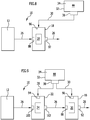
- FIG. 9 schematically illustrated system 10 includes all components of in FIG. 8 However, a second treatment chamber 22 between the combustion device 12 and the first treatment chamber 18 is additionally arranged here. From the combustion device 12, the exhaust gas 26 is passed through a second exhaust inlet 100 into the second treatment chamber 22.
- the oxidant 28 produced by the electrolyzer 38 during electrolysis is introduced through the oxidant inlet 94 into the second treatment chamber 22 in which the oxidation catalyst 24 is disposed.
- the thus at least partially oxidized exhaust gas 26 is discharged through a second exhaust gas outlet 102, which is fluidly connected to the first exhaust gas inlet 88, and fed to the first treatment chamber 18.
- a reduction of combustion products contained in the exhaust 26 instead.
- FIG. 10 schematically illustrated embodiment of a system 10 includes only a first treatment chamber 18. In this, however, not only the reduction catalyst 20 is arranged, but also, but spatially separated, the oxidation catalyst 24th
- Exhaust gas 26 from the combustion device 28 is introduced through the first exhaust gas inlet 88 into the first treatment chamber 18 and first flows through the corresponding spatially arranged oxidation catalyst 24th
- the oxidant generated by the electrolyzer 38 is introduced through the oxidant inlet 94 into the first treatment chamber 18, in a region where the oxidation catalyst 24 is disposed.
- the reducing agent generated by the electrolysis device 38 is introduced through the reducing agent inlet 96 into the first treatment chamber 18 in the region of the reduction catalytic converter 20 arranged therein.
- FIG. 11 Another embodiment of a system 10 is shown schematically in FIG. 11 shown. It essentially corresponds to the one in FIG. 9 illustrated and described above system 10.
- systems 10 may also include a control and / or regulating device 62. Such is the sake of clarity in the FIGS. 8 to 11 not shown.
- FIG. 12 schematically illustrated system 26 includes such a control and / or regulating device 62. This is connected to the electrolysis device 38 control effective, in particular by the amount of generated reducing agent 30 and oxidizing agent 28 to control and / or to regulate.
- the exhaust gas 26 of the combustion device 12 is first supplied to the second treatment chamber 22 through the second exhaust gas inlet 100.
- Oxidant 28 which is generated by the electrolysis device 38, is supplied to the second treatment chamber 22 as required by the oxidant inlet 94.
- the exhaust 26 having partially oxidized combustion products is exhausted through the second exhaust outlet 102 and supplied to the diesel particulate filter 64 through an inlet 104.
- the measuring device 68 for measuring the nitrogen oxide content in the exhaust gas 26 is arranged or formed.
- the measuring device 68 is connected to the control and / or regulating device 62 with control effect.
- the exhaust gas 26 flows through an outlet 106 and is supplied to the oxidation catalyst chamber 66 through its inlet 108.
- the temperature measuring device 74 With the temperature measuring device 74, the temperature of the exhaust gas in the oxidation catalyst chamber 66 is measured.
- Reductant 30 generated by the electrolyzer 38 is introduced into the oxidation catalyst chamber 66 through the reductant inlet 72.
- the exhaust gas 26 discharged through the outlet 110 of the oxidation catalyst chamber 66 is supplied to the first processing chamber 18 after the admixture of reducing agent 30 through the first exhaust gas inlet 88.
- a further measuring device 80 for measuring the nitrogen oxide content in the exhaust gas 26 is arranged or formed. This is in turn connected to the control and / or regulating device 62 with control effect.
- the generation as well as the supply of reducing agent 30 and oxidizing agent 28 can be controlled and / or regulated in a targeted manner as a function of the measured values determined with the measuring devices 68 and 80 and the temperature measuring device 74.
- the illustrated systems 10 may further include valves for controlling the supply of reducing agent 30 and oxidizing agent 28 into the first and / or second treatment chambers 18, 22, respectively, and optionally corresponding pumping means.
- a heating device 112 for heating the exhaust treatment agent reservoir 32 may also be provided in each system 10 in order to keep the exhaust treatment agent 34 in the liquid phase or, if appropriate, to re-liquefy the systems 10 in vehicles at temperatures below freezing.
- the systems described above may be used for exhaust treatment in conjunction with combustion devices 12 not only in the form of internal combustion engines 14 but also in the form of furnaces, waste incinerators, gas turbines or industrial plants.
- the reducing agent 30 is generated in a targeted and easily controllable manner by electrolysis.
- the described systems 10 are all nitric oxide storage-free or a nitrogen oxide trap-free. This simplifies the structure the systems 10 as well as their operation, since no regeneration cycles must be controlled and / or regulated by a control and / or regulating device 62. In addition, the entire exhaust gas produced by the combustion device 12 can be treated continuously in a desired manner.
Abstract
Um ein System zur Abgasbehandlung von Verbrennungsvorrichtungen, insbesondere von Verbrennungsmotoren, umfassend eine erste Behandlungskammer mit einem ersten Abgaseinlass, einem ersten Abgasauslass, einem Reduktionsmitteleinlass und einem Reduktionskatalysator, welcher erste Abgaseinlass direkt oder indirekt mit der Verbrennungsvorrichtung fluidwirksam verbindbar ist, wobei das System einen Abgasbehandlungsmittelspeicher zum Speichern eines Abgasbehandlungsmittels und eine Reduktionsmittelerzeugungseinrichtung zum Erzeugen eines Reduktionsmittels aus dem Abgasbehandlungsmittel umfasst, zu verbessern, wird vorgeschlagen, dass die Reduktionsmittelerzeugungseinrichtung in Form einer Elektrolyseeinrichtung zum Erzeugen des Reduktionsmittels aus dem Abgasbehandlungsmittel durch Elektrolyse ausgebildet ist.To provide a system for exhaust treatment of combustion devices, particularly internal combustion engines, comprising a first treatment chamber having a first exhaust inlet, a first exhaust outlet, a reducing agent inlet and a reduction catalyst, which first exhaust inlet is directly or indirectly fluidly connectable to the combustion device, the system including an exhaust treatment agent reservoir Saving an exhaust gas treatment agent and a reducing agent generating means for generating a reducing agent from the exhaust gas treatment agent comprises, it is proposed that the reducing agent generating means in the form of an electrolysis device for generating the reducing agent from the exhaust gas treatment agent is formed by electrolysis.
Ferner wird ein verbessertes Verfahren zur Abgasbehandlung von Verbrennungsvorrichtungen vorgeschlagen.

Description
Die vorliegende Erfindung betrifft ein System zur Abgasbehandlung von Verbrennungsvorrichtungen, insbesondere von Verbrennungsmotoren, umfassend eine erste Behandlungskammer mit einem ersten Abgaseinlass, einem ersten Abgasauslass, einem Reduktionsmitteleinlass und einem Reduktionskatalysator, welcher erste Abgaseinlass direkt oder indirekt mit der Verbrennungsvorrichtung fluidwirksam verbindbar ist, wobei das System einen Abgasbehandlungsmittelspeicher zum Speichern eines Abgasbehandlungsmittels und eine Reduktionsmittelerzeugungseinrichtung zum Erzeugen eines Reduktionsmittels aus dem Abgasbehandlungsmittel umfasst.The present invention relates to a system for exhaust gas treatment of combustion devices, in particular of internal combustion engines, comprising a first treatment chamber having a first exhaust inlet, a first exhaust outlet, a reducing agent inlet and a reduction catalyst, which first exhaust inlet is directly or indirectly fluidly connectable to the combustion device, the system an exhaust gas treatment agent reservoir for storing an exhaust gas treatment agent and a reducing agent generation device for generating a reducing agent from the exhaust gas treatment agent.
Ferner betrifft die vorliegende Erfindung eine Verbrennungsvorrichtung umfassend ein solches System zur Abgasbehandlung.Furthermore, the present invention relates to a combustion device comprising such a system for exhaust gas treatment.
Des Weiteren betrifft die Erfindung ein Verfahren zur Abgasbehandlung von Verbrennungsvorrichtungen, insbesondere von Verbrennungsmotoren, umfassend das Reduzieren von Verbrennungsprodukten in Abgasen mit einem Reduktionsmittel unter Verwendung eines Reduktionskatalysators, das Bereitstellen eines Abgasbehandlungsmittels und das Erzeugen des Reduktionsmittels aus dem Abgasbehandlungsmittel.The invention further relates to a method for treating exhaust gas of combustion devices, in particular of internal combustion engines, comprising reducing combustion products in exhaust gases with a reducing agent using a reduction catalyst, providing an exhaust gas treatment agent and generating the reducing agent from the exhaust gas treatment agent.
Systeme und Verfahren zur Abgasbehandlung von Verbrennungsvorrichtungen sind in unterschiedlichen Varianten bekannt. Insbesondere ist es bekannt, im Abgas von Verbrennungsvorrichtungen, insbesondere von Verbrennungsmotoren, Stickoxide durch selektive katalytische Reduktion mit einem Reduktionskatalysator zu verringern. Die Stickoxide NO und NO2 werden dabei reduziert. Hierfür wird Ammoniak benötigt. Dieser wird aus einer Harnstofflösung durch Thermolyse und Hydrolyse erzeugt. So können die Stickoxide zu molekularem Stickstoff und Wasser abgebaut werden. Derartige Systeme und Verfahren werden beispielsweise bei Kraftfahrzeugen, insbesondere Dieselfahrzeugen, erfolgreich in Serie eingesetzt. Sie ermöglichen die kontinuierliche Abgasbehandlung, ohne dass Teile oder Elemente des Systems regeneriert werden müssen.Systems and methods for exhaust treatment of combustion devices are known in different variants. In particular, it is known to reduce nitrogen oxides in the exhaust gas of combustion devices, in particular internal combustion engines, by selective catalytic reduction with a reduction catalyst. The nitrogen oxides NO and NO 2 are reduced. This requires ammonia. This is produced from a urea solution by thermolysis and hydrolysis. Thus, the nitrogen oxides can be degraded to molecular nitrogen and water. Such systems and methods For example, in motor vehicles, especially diesel vehicles, used successfully in series. They enable continuous exhaust gas treatment without the need to regenerate parts or elements of the system.
Neueste Studien belegen jedoch, dass diese bekannte selektive katalytische Reduktion von Stickoxiden durch Einsatz von Harnstoff zwar sehr effektiv ist, jedoch auch andere Emissionen wie Ammoniak (NH3), Distickstoffoxid (N2O), Isocyansäure (HNCO), Kohlenwasserstoffe mit Treibhauseffekt (CH4, C3H8 und nC8) sowie assoziierte sekundäre Feinstoffbildung durch Ammoniumnitrat und Ammoniumsulfat erhöhen. Diese Stoffe werden teilweise als höchst toxisch für Mensch und Umwelt eingestuft. Daher muss aufwändig sichergestellt werden, dass ihr Anteil in den Abgasen unter den jeweils vorgegebenen Grenzwerten verbleibt.However, recent studies show that this well-known selective catalytic reduction of nitrogen oxides by using urea is indeed very effective, but also other emissions such as ammonia (NH 3 ), nitrous oxide (N 2 O), isocyanic acid (HNCO), hydrocarbons with greenhouse effect (CH 4 , C 3 H 8 and nC 8 ) as well as associated secondary fines formation by ammonium nitrate and ammonium sulfate. These substances are sometimes classified as highly toxic to humans and the environment. Therefore, it must be laboriously ensured that their share in the exhaust gases remains below the respective specified limit values.
Ferner ist die Herstellung des benötigten Harnstoffs nach dem bekannten Haber-Bosch-Verfahren sehr energieintensiv und stellt eine große CO2-Emissionsquelle dar.Furthermore, the production of the required urea according to the known Haber-Bosch process is very energy-intensive and represents a large source of CO 2 emission.
Zudem muss für den Betrieb eines Kraftfahrzeugs sichergestellt werden, dass zum Betreiben desselben Harnstoff als Abgasbehandlungsmittel in wässriger Lösung zur Verfügung steht.In addition, it must be ensured for the operation of a motor vehicle that urea is available for operating the same as an exhaust gas treatment agent in aqueous solution.
Zudem sind Systeme bekannt, beispielsweise aus der
Ferner ist zu berücksichtigen, dass NOx-Speicher auf Basis von Alkali- und Erdalkalimetalle auch Schwefeloxide adsorbieren, die bei der motorischen Verbrennung aus dem im Kraftstoff enthaltenen Schwefel entstehen können, in Form von Sulfaten. Eine Schwefel-Regeneration findet deshalb erst bei höheren Temperaturen statt, als sie für eine Regeneration des NOx-Speichers erforderlich sind. Daher kommt es mit fortschreitender Zeit zu einer Blockade der Speicherelemente, so dass die NOx-Speicherfähigkeit empfindlich abnimmt.It should also be taken into account that NO x stores based on alkali metals and alkaline earth metals also adsorb sulfur oxides which, in the case of engine combustion, can be formed from the sulfur contained in the fuel, in the form of sulphates. Therefore, a sulfur regeneration takes place only at higher temperatures than are required for a regeneration of the NO x storage. Therefore, as the time progresses, the memory elements become blocked, so that the NO x storage capability is lowered sensitively.
Es ist daher eine Aufgabe der vorliegenden Erfindung, ein System und ein Verfahren der eingangs beschriebenen Art weiter zu verbessern.It is therefore an object of the present invention to further improve a system and a method of the type described above.
Diese Aufgabe wird bei einem System der eingangs beschriebenen Art erfindungsgemäß dadurch gelöst, dass die Reduktionsmittelerzeugungseinrichtung in Form einer Elektrolyseeinrichtung zum Erzeugen des Reduktionsmittels aus dem Abgasbehandlungsmittel durch Elektrolyse ausgebildet ist.This object is achieved in a system of the type described above according to the invention that the reducing agent generating means in the form of an electrolysis device for generating the reducing agent from the exhaust gas treatment agent is formed by electrolysis.
Eine solche Elektrolyseeinrichtung hat insbesondere den Vorteil, dass das Reduktionsmittel nach Bedarf erzeugt werden kann. Insbesondere lässt sich die Erzeugung des Reduktionsmittels bedarfsabhängig steuern und gegebenenfalls auch regeln. So kann insbesondere auf die Verwendung von Harnstofflösungen verzichtet werden. Die Thermolyse und Hydrolyse des Harnstoffs lässt sich deutlich schlechter, wenn überhaupt steuern. Zudem gibt es bei Harnstoff das Problem, dass Harnstofflösungen im Laufe der Zeit degradieren. Damit erfordert der Einsatz von Harnstofflösungen insbesondere auch eine kontinuierliche Messung einer Konzentration des Harnstoffs in der Lösung. Insbesondere die bedarfsabhängige Erzeugung des Reduktionsmittels ermöglicht es, diese Nachteile zu überwinden. Ferner ist eine Abgasbehandlung vollständig ohne Stickoxid-Speicher oder Stickoxidfallen möglich und damit eine kontinuierliche Abgasbehandlung. Mithin kann also insbesondere eine Stickoxid-Speicher-freies System beziehungsweise ein Stickoxidfallen-freies System ausgebildet werden. Dies hat insbesondere den Vorteil, dass keine Regeneration des Stickoxid-Speichers oder der Stickoxidfalle erforderlich ist. Mithin kann also insbesondere das gesamte von der Verbrennungseinrichtung erzeugte Abgas in gewünschter Weise kontinuierlich behandelt werden. Die Abgasbehandlung kann also insbesondere in der ersten Behandlungskammer direkt mit dem Reduktionsmittel ohne irgendwelche Speicher erfolgen. Ferner vereinfacht sich der Aufbau des Systems, da keine Speicher oder Fallen für NOx benötigt werden. Auch eine Steuerung des Systems vereinfacht sich aus diesem Grund.Such an electrolysis device has the particular advantage that the reducing agent can be generated as needed. In particular, the generation of the reducing agent can be controlled as needed and optionally also regulated. In particular, it is possible to dispense with the use of urea solutions. The thermolysis and hydrolysis of urea can be significantly worse, if any control. In addition, urea has the problem that urea solutions degrade over time. Thus, the use of urea solutions in particular also requires a continuous measurement of a concentration of urea in the solution. In particular, the demand-dependent generation of the reducing agent makes it possible to overcome these disadvantages. Furthermore, an exhaust treatment is completely without nitrogen oxide storage or nitrogen oxide traps possible and thus a continuous exhaust treatment. Thus, therefore, in particular a nitrogen oxide storage-free system or a nitrogen oxide trap-free system can be formed. This has the particular advantage that no regeneration of the nitrogen oxide storage or the nitrogen oxide trap is required. Thus, therefore, in particular the entire exhaust gas generated by the combustion device can be treated continuously in the desired manner. The exhaust gas treatment can thus be carried out directly in particular in the first treatment chamber with the reducing agent without any memory. Furthermore, the structure of the system is simplified, since no storage or traps for NO x are needed. Also a control of the system is simplified for this reason.
Vorzugsweise ist die Elektrolyseeinrichtung in Form eines Wasserelektrolyseurs ausgebildet. Ein Wasserelektrolyseur ermöglicht es, Wasser durch Elektrolyse in molekularen Wasserstoff und molekularen Sauerstoff zu trennen. Insbesondere kann der molekulare Wasserstoff genutzt werden, um Stickstoffmonoxid und Stickstoffdioxid zu reduzieren, insbesondere unter Bildung von Stickstoff und Wasser. Optional kann der durch Elektrolyse erzeugte Sauerstoff genutzt werden, um Stickstoffmonoxid zu Stickstoffdioxid zu oxidieren. Die Erzeugung der Elektrolyseprodukte Wasserstoff und Sauerstoff lässt sich bei einem Wasserelektrolyseur auf einfache Weise steuern und gegebenenfalls auch regeln. So kann immer die im Betrieb der Verbrennungsvorrichtung erforderliche Menge an Wasserstoff als Reduktionsmittel und gegebenenfalls auch Sauerstoff als Oxidationsmittel erzeugt werden, um so das Abgas optimal zu behandeln und insbesondere von Stickoxiden zu befreien.Preferably, the electrolysis device is designed in the form of a water electrolyzer. A water electrolyzer makes it possible to separate water by electrolysis into molecular hydrogen and molecular oxygen. In particular, the molecular hydrogen may be utilized to reduce nitrogen monoxide and nitrogen dioxide, particularly to form nitrogen and water. Optionally, the oxygen produced by electrolysis can be used to oxidize nitrogen monoxide to nitrogen dioxide. The production of the electrolysis products hydrogen and oxygen can be controlled in a simple way with a water electrolyzer and optionally also regulate. Thus, it is always possible to generate the amount of hydrogen required as a reducing agent and optionally also oxygen as an oxidizing agent during operation of the combustion device so as to optimally treat the exhaust gas and, in particular, to liberate it from nitrogen oxides.
Vorzugsweise ist die Elektrolyseeinrichtung in Form einer kammergetrennten Elektrolyseeinrichtung ausgebildet zum Trennen des bei der Elektrolyse entstehenden Reduktionsmittels von dem entstehenden Oxidationsmittel. Eine solche Elektrolyseeinrichtung ermöglicht es insbesondere, die erzeugten Elektrolyseprodukte getrennt voneinander zu nutzen. Insbesondere kann dadurch auch verhindert werden, dass die Elektrolyseprodukte wieder miteinander reagieren. Insbesondere bei der Elektrolyse von Wasser sollte dies vermieden werden, da Mischungen aus molekularem Wasserstoff und Sauerstoff bei entsprechenden Mischungsverhältnissen hochexplosiv sind. Ferner erlaubt es ein kammergetrennter Elektrolyseur, die Elektrolyseprodukte gezielt dorthin zu leiten oder zu führen, wo sie benötigt werden. Optional können sie auch zwischengespeichert werden. Ein solcher kammergetrennter Elektrolyseur kann insbesondere in Form eines elektrochemischen Membranreaktors ausgebildet sein.The electrolysis device is preferably designed in the form of a chamber-separated electrolysis device for separating the reducing agent formed during the electrolysis from the resulting oxidizing agent. Such an electrolysis device makes it possible, in particular, to use the produced electrolysis products separately from one another. In particular, this can also be prevented that the electrolysis products react with each other again. Especially in the electrolysis of water this should be be avoided, since mixtures of molecular hydrogen and oxygen at high mixing ratios are highly explosive. Furthermore, a chamber-separated electrolyzer allows the electrolysis products to be directed or guided to where they are needed. Optionally, they can also be cached. Such a chamber-separated electrolyzer may be designed in particular in the form of an electrochemical membrane reactor.
Vorteilhaft ist es, wenn die Elektrolyseeinrichtung fluidwirksam mit der ersten Behandlungskammer verbunden ist zum Zuführen des erzeugten Reduktionsmittels zur ersten Behandlungskammer. So kann das Reduktionsmittel in gewünschter Weise und insbesondere auch in gewünschter Menge und Dosierung der ersten Behandlungskammer zugeführt werden, um im Abgas enthaltene Verbrennungsprodukte zu reduzieren.It is advantageous if the electrolysis device is connected fluid-effectively to the first treatment chamber for supplying the generated reducing agent to the first treatment chamber. Thus, the reducing agent can be supplied in the desired manner and in particular in the desired amount and dosage of the first treatment chamber to reduce combustion products contained in the exhaust gas.
Gemäß einer weiteren bevorzugten Ausführungsform der Erfindung kann vorgesehen sein, dass das System eine zweite Behandlungskammer umfasst mit einem zweiten Abgaseinlass, einem zweiten Abgasauslass, einem Oxidationsmitteleinlass und einem Oxidationskatalysator. Ein derart weitergebildetes System ermöglicht es insbesondere, im Abgas enthaltene Verbrennungsprodukte gezielt weiter zu oxidieren, um die Bildung unerwünschter Nebenprodukte zu vermeiden. Beispielsweise kann so Stickstoffmonoxid durch Zugabe von molekularem Sauerstoff als Oxidationsmittel zu Stickstoffdioxid oxidiert werden. Stickstoffdioxid lässt sich dann in bekannter Weise durch Zugabe von molekularem Wasserstoff zu molekularem Stickstoff unter Bildung von Wasser reduzieren. Auch hierfür bedarf eines keines Stickoxid-Speichers, welcher bei Erreichen seiner Aufnahmekapazität regeneriert werden muss. Das erfindungsgemäße System ist also insbesondere Stickoxid-Speicher-frei beziehungsweise Stickoxidfallen-frei ausgebildet. Das System ist daher kontinuierlich arbeitend ausgebildet im Gegensatz zu einem quasikontinuierlichen oder intermittierenden Betrieb bei Einsatz ein Stickoxid-Speichern oder Stickoxidfallen.According to a further preferred embodiment of the invention, it can be provided that the system comprises a second treatment chamber with a second exhaust gas inlet, a second exhaust gas outlet, an oxidant inlet and an oxidation catalyst. A system developed in this way makes it possible, in particular, to further selectively oxidise combustion products contained in the exhaust gas in order to avoid the formation of undesired by-products. For example, nitrogen monoxide can be oxidized to nitrogen dioxide by adding molecular oxygen as the oxidizing agent. Nitrogen dioxide can then be reduced in a known manner by adding molecular hydrogen to molecular nitrogen to form water. Again, this requires no nitric oxide storage, which must be regenerated when it reaches its absorption capacity. The system according to the invention is thus in particular designed to be free of nitrogen oxide storage or of nitrogen oxide trap. The system is therefore designed to operate continuously in contrast to a quasi-continuous or intermittent operation when using a nitrogen oxide storage or nitrogen oxide traps.
Vorzugsweise ist der zweite Abgasauslass fluidwirksam mit dem ersten Abgaseinlass verbunden. Dies ermöglicht es insbesondere, das Abgas beziehungsweise die darin enthaltenen Verbrennungsprodukte zunächst weiter zu oxidieren und die so oxidierten Verbrennungsprodukte aus der zweiten Behandlungskammer in die erste Behandlungskammer zu leiten, um sie dort in gewünschter Weise zu reduzieren.Preferably, the second exhaust outlet is fluidly connected to the first exhaust inlet. This makes it possible, in particular, first to further oxidize the exhaust gas or the combustion products contained therein and to conduct the so-oxidized combustion products from the second treatment chamber into the first treatment chamber in order to reduce it there in the desired manner.
Vorteilhaft ist es, wenn der Abgasbehandlungsmittelspeicher in Form eines Wasserspeichers ausgebildet ist. Wasser lässt sich auf einfache Weise speichern und ist leicht verfügbar. Anders als bei Harnstofflösungen ist hier keine Degradation zu fürchten. Anders als bei Harnstofflösungen muss hier keine Konzentration überwacht und gemessen werden. Zudem sind keine weiteren Chemikalien für die Abgasbehandlung erforderlich. Des Weiteren kann beim Einsatz von Wasser nicht nur der durch Elektrolyse erzeugte molekulare Wasserstoff zur Abgasbehandlung genutzt werden, sondern auch der erzeugte molekulare Sauerstoff. Ein solches System ist für einen Anwender leicht handhabbar und insbesondere auch für Großserien gut umsetzbar.It is advantageous if the exhaust gas treatment agent reservoir is designed in the form of a water reservoir. Water is easy to store and is readily available. Unlike urea solutions, there is no danger of degradation here. Unlike urea solutions, no concentration needs to be monitored and measured here. In addition, no further chemicals are required for the exhaust gas treatment. Furthermore, when using water, not only the molecular hydrogen produced by electrolysis can be used for the exhaust gas treatment, but also the generated molecular oxygen. Such a system is easy to handle for a user and especially well suited for mass production.
Vorzugsweise ist das Abgasbehandlungsmittel Wasser. Wie bereits beschrieben ist Wasser völlig ungefährlich und leicht verfügbar. Es kann von einem Anwender bei Bedarf jederzeit und überall nachgefüllt werden. Zudem ist es kostengünstig verfügbar.Preferably, the exhaust gas treatment agent is water. As already described, water is completely harmless and readily available. It can be refilled anytime, anywhere by a user as needed. In addition, it is available at low cost.
Um das Abgasbehandlungsmittel wie gewünscht elektrolysieren zu können, ist es vorteilhaft, wenn die Elektrolyseeinrichtung mit dem Abgasbehandlungsmittelspeicher fluidwirksam verbunden ist.In order to be able to electrolyze the exhaust gas treatment agent as desired, it is advantageous if the electrolysis device is fluidically connected to the exhaust gas treatment agent reservoir.
Vorteilhaft ist es, wenn die Elektrolyseeinrichtung im Abgasbehandlungsmittelspeicher angeordnet oder ausgebildet ist. So lässt sich das System besonders kompakt ausbilden.It is advantageous if the electrolysis device is arranged or formed in the exhaust gas treatment agent reservoir. This makes the system particularly compact.
Vorteilhafterweise umfasst das System eine Heizeinrichtung zum Beheizen des Abgasbehandlungsmittelspeichers. Insbesondere dann, wenn als Abgasbehandlungsmittel Wasser verwendet wird, ist eine solche Heizeinrichtung vorteilhaft, um das Abgasbehandlungsmittel in flüssiger Phase zu halten. Insbesondere kann es so auf eine gewünschte Temperatur erwärmt werden, bei der die Elektrolyse des Abgasbehandlungsmittels besonders effizient durchgeführt werden kann.Advantageously, the system includes a heater for heating the exhaust treatment agent storage. In particular, if as exhaust gas treatment agent Water is used, such a heater is advantageous to keep the exhaust gas treatment agent in the liquid phase. In particular, it can be heated to a desired temperature at which the electrolysis of the exhaust gas treatment agent can be carried out particularly efficiently.
Günstig ist es, wenn der Reduktionskatalysator Palladium ist oder enthält. Palladium kann insbesondere auch auf einem Träger bereitgestellt werden. Palladium eignet sich insbesondere hervorragend zur Unterstützung der Reduktion von Stickoxiden mittels molekularen Wasserstoffs.It is favorable if the reduction catalyst is or contains palladium. In particular, palladium can also be provided on a carrier. In particular, palladium is outstandingly suitable for supporting the reduction of nitrogen oxides by means of molecular hydrogen.
Vorteilhaft ist es, wenn der Oxidationskatalysator Platin ist oder enthält. Insbesondere kann das Platin auf einem Träger bereitgestellt werden. Platin eignet sich als hocheffizienter Katalysator für eine Oxidation von Stickoxiden durch molekularen Sauerstoff.It is advantageous if the oxidation catalyst is platinum or contains. In particular, the platinum can be provided on a carrier. Platinum is a highly efficient catalyst for the oxidation of nitrogen oxides by molecular oxygen.
Gemäß einer weiteren bevorzugten Ausführungsform der Erfindung kann vorgesehen sein, dass das System eine Messeinrichtung zum Messen eines NOx-Gehalts des in die erste Behandlungskammer einströmenden Abgases umfasst. Die Messeinrichtung ermöglicht es insbesondere, den NOx-Gehalt zu bestimmen und den Messwert insbesondere zu nutzen, um die Menge des zugeführten Reduktionsmittels zur ersten Behandlungskammer zu steuern und/oder zu regeln. Insbesondere kann ein solcher Messwert auch genutzt werden, um die Elektrolyseeinrichtung zu steuern und/oder zu regeln. So kann abhängig vom gemessenen NOx-Gehalt die erforderliche Menge an Reduktionsmittel erzeugt und in definierter Menge und Dosierung der ersten Behandlungskammer zugeführt werden.According to a further preferred embodiment of the invention, it can be provided that the system comprises a measuring device for measuring an NO x content of the exhaust gas flowing into the first treatment chamber. In particular, the measuring device makes it possible to determine the NO x content and in particular to use the measured value in order to control and / or regulate the amount of the reducing agent supplied to the first treatment chamber. In particular, such a measured value can also be used to control and / or regulate the electrolysis device. Thus, depending on the measured NO x content, the required amount of reducing agent can be generated and fed in a defined amount and dosage of the first treatment chamber.
Ferner ist es vorteilhaft, wenn das System eine Temperaturmesseinrichtung zum Messen einer Temperatur des Abgases in der ersten Behandlungskammer umfasst. Insbesondere kann die gemessene Temperatur des Abgases genutzt werden, um die Zufuhr des Reduktionsmittels zu steuern und/oder zu regeln und optional auch die Elektrolyseeinrichtung temperaturabhängig zu steuern und/oder zu regeln.Furthermore, it is advantageous if the system comprises a temperature measuring device for measuring a temperature of the exhaust gas in the first treatment chamber. In particular, the measured temperature of the exhaust gas can be used to control and / or regulate the supply of the reducing agent and optionally also to control and / or regulate the electrolysis device in a temperature-dependent manner.
Ferner ist es günstig, wenn das System eine Reduktionsmittelzuführeinrichtung zum Zuführen des Reduktionsmittels zur ersten Behandlungskammer umfasst. Insbesondere kann die Reduktionsmittelzuführeinrichtung eine Pumpeinrichtung und/oder eine Dosiereinrichtung umfassen, um das Reduktionsmittel, insbesondere wenn es gasförmig ist, in gewünschter Menge und unter gewünschtem Druck, in die erste Behandlungskammer zu leiten.Furthermore, it is favorable if the system comprises a reducing agent supply device for supplying the reducing agent to the first treatment chamber. In particular, the reducing agent supply means may comprise a pumping device and / or a metering device for directing the reducing agent into the first treatment chamber, in particular when it is gaseous, in the desired amount and under the desired pressure.
Ferner kann es vorteilhaft sein, wenn das System eine Oxidationsmittelzuführeinrichtung zum Zuführen des Oxidationsmittels zur zweiten Behandlungskammer umfasst. Die Oxidationsmittelzuführeinrichtung kann insbesondere eine Pumpeinrichtung und/oder eine Dosiereinrichtung umfassen, um das Oxidationsmittel in gewünschter Menge und, wenn es gasförmig vorliegt, auch unter einem definierten Druck, in die zweite Behandlungskammer einzuleiten.Furthermore, it may be advantageous if the system comprises an oxidant supply device for supplying the oxidizing agent to the second treatment chamber. The oxidant supply device may in particular comprise a pumping device and / or a metering device in order to introduce the oxidizing agent in the desired amount and, if present in gaseous form, also under a defined pressure, into the second treatment chamber.
Günstig ist es, wenn das System eine Steuer- und/oder Regelungseinrichtung umfasst zum Steuern und/oder Regeln der Elektrolyseeinrichtung und/oder der Reduktionsmittelzuführeinrichtung und/oder der Oxidationsmittelzuführeinrichtung. Insbesondere kann die Steuer- und/oder Regelungseinrichtung ausgebildet sein, um die Elektrolyseeinrichtung und/oder die Reduktionsmittelzuführeinrichtung und/oder die Oxidationsmittelzuführeinrichtung in Abhängigkeit des mit der Messeinrichtung bestimmten NOx-Gehalts des in die erste Behandlungskammer einströmenden Abgases und/oder in Abhängigkeit der mit der Temperaturmesseinrichtung gemessenen Temperatur des Abgases in der ersten Behandlungskammer zu steuern und/oder zu regeln. Insbesondere kann so auf einfache Weise bedarfsabhängig die Menge erforderlichen Reduktionsmittels und optional auch erforderlichen Oxidationsmittels in definierter Weise gesteuert und/oder geregelt werden.It is advantageous if the system comprises a control and / or regulating device for controlling and / or regulating the electrolysis device and / or the reducing agent supply device and / or the oxidizing agent supply device. In particular, the control and / or regulating device may be designed to the electrolysis device and / or the Reduktionsmittelzuführeinrichtung and / or the Oxidationsmittelzuführeinrichtung depending on the determined with the measuring device NO x content of the inflowing into the first treatment chamber exhaust gas and / or in dependence of to control the temperature measuring device measured temperature of the exhaust gas in the first treatment chamber and / or to regulate. In particular, the amount of reducing agent required and optionally also required oxidizing agent can thus be controlled and / or regulated in a defined manner in a defined manner in a simple manner as required.
Besonders einfach und kompakt ausbilden lässt sich das System, wenn der erste Abgaseinlass mit dem Reduktionsmitteleinlass fluidwirksam verbunden ist oder den Reduktionsmitteleinlass bildet. So kann dem Abgas bereits vor dem Einströmen in die erste Behandlungskammer das Reduktionsmittel zugeführt werden. So kann eine optimale Durchmischung des Abgases und des Reduktionsmittels erreicht und damit eine Effizienz der Reduktionsreaktion in der ersten Behandlungskammer verbessert werden.The system can be designed in a particularly simple and compact manner when the first exhaust gas inlet is connected to the reducing agent inlet in a fluid-efficient manner or forms the reductant inlet. Thus, the reducing agent can be supplied to the exhaust gas before it flows into the first treatment chamber. Thus, optimum mixing of the exhaust gas and the reducing agent can be achieved and thus an efficiency of the reduction reaction in the first treatment chamber can be improved.
Die eingangs gestellte Aufgabe wird insbesondere bei einer Verbrennungsvorrichtung der eingangs beschriebenen Art erfindungsgemäß dadurch gelöst, dass sie eines der oben beschriebenen, weitergebildeten Systeme zur Abgasbehandlung umfasst.The object stated in the introduction is achieved according to the invention, in particular in a combustion device of the type described in the introduction, by comprising one of the above-described, further developed systems for exhaust gas treatment.
Eine Verbrennungsvorrichtung, die mit derartigen Systemen zur Abgasbehandlung zusammenwirkt oder eines derselben umfasst, ermöglicht es insbesondere, unerwünschte Verbrennungsprodukte im Abgas, beispielsweise Stickoxide, durch definierte Reduktion und/oder Oxidation einfach und sicher zu entfernen.A combustion device which interacts with or includes one of these systems for exhaust gas treatment makes it possible, in particular, to easily and safely remove undesirable combustion products in the exhaust gas, for example nitrogen oxides, by defined reduction and / or oxidation.
Günstigerweise ist die Verbrennungsvorrichtung in Form eines Verbrennungsmotors, einer Feuerungsanlage, einer Müllverbrennungsanlage, einer Gasturbine oder einer Industrieanlage ausgebildet. Insbesondere entstehen beim Betrieb derartiger Verbrennungsvorrichtungen in unerwünschter Weise Stickoxide. Diese lassen sich mit einem der oben beschriebenen weitergebildeten Systeme zur Abgasbehandlung auf einfache und definierte Weise in unschädliche Reaktionsprodukte umwandeln, insbesondere in molekularen Stickstoff und Wasser. Insbesondere beim Einsatz von Wasser als Abgasbehandlungsmittel kann so auf eine kostenintensive Herstellung von Harnstofflösungen verzichtet werden. Wasserstoff kann durch Elektrolyse auch in großem Maßstab auf einfache Weise erzeugt werden, sodass auch bei großen Anlagen, insbesondere bei der Müllverbrennung, bei Industrieanlagen und beim Betrieb von Gasturbinen erzeugte Stickoxide einfach und sicher abgebaut werden können.Conveniently, the combustion device in the form of an internal combustion engine, a combustion plant, a waste incineration plant, a gas turbine or an industrial plant is formed. In particular, nitrogen oxides are undesirably produced during the operation of such combustion devices. These can be converted in a simple and defined manner into harmless reaction products with one of the further described systems for the treatment of exhaust gas, in particular in molecular nitrogen and water. In particular, when using water as an exhaust gas treatment agent can be dispensed with a costly production of urea solutions. Hydrogen can be produced by electrolysis on a large scale in a simple manner, so that even in large plants, especially in waste incineration, industrial plants and in the operation of gas turbines generated nitrogen oxides can be degraded easily and safely.
Die eingangs gestellte Aufgabe wird ferner bei einem Verfahren der eingangs beschriebenen Art erfindungsgemäß dadurch gelöst, dass das Reduktionsmittel aus dem Abgasbehandlungsmittel durch Elektrolyse erzeugt wird.The object stated in the introduction is also achieved in a method of the type described above according to the invention in that the reducing agent is generated from the exhaust gas treatment agent by electrolysis.
Das erfindungsgemäß weitergebildete Verfahren ermöglicht es, das Reduktionsmittel ganz gezielt dann zu erzeugen, wenn es benötigt wird. Es kann insbesondere in der Menge erzeugt werden, die für eine optimale Behandlung des Abgases erforderlich ist, insbesondere zum Abbau unerwünschter Verbrennungsprodukte im Abgas. Bei diesen kann es sich insbesondere um Stickoxide handeln. Zudem kann die Abgasbehandlung vollständig ohne Stickoxid-Speicher oder Stickoxidfallen durchgeführt und damit eine kontinuierliche Abgasbehandlung erreicht werden. Mithin kann also insbesondere eine Stickoxid-Speicher-freies Verfahren beziehungsweise ein Stickoxidfallen-freies Verfahren durchgeführt werden. Dies hat insbesondere den Vorteil, dass keine Regeneration des Stickoxid-Speichers oder der Stickoxidfalle erforderlich ist. Mithin kann also insbesondere das gesamte von der Verbrennungseinrichtung erzeugte Abgas in gewünschter Weise kontinuierlich behandelt werden.The method further developed according to the invention makes it possible to generate the reducing agent quite purposefully when it is needed. In particular, it can be produced in the amount required for optimum treatment of the exhaust gas, in particular for reducing undesired combustion products in the exhaust gas. These may in particular be nitrogen oxides. In addition, the exhaust gas treatment can be carried out completely without nitrogen oxide storage or nitrogen oxide traps and thus a continuous exhaust gas treatment can be achieved. Consequently, therefore, in particular a nitrogen oxide storage-free process or a nitrogen oxide trap-free process can be carried out. This has the particular advantage that no regeneration of the nitrogen oxide storage or the nitrogen oxide trap is required. Thus, therefore, in particular the entire exhaust gas generated by the combustion device can be treated continuously in the desired manner.
Vorzugsweise wird das Reduktionsmittel durch Elektrolyse von Wasser erzeugt. So kann insbesondere molekularer Wasserstoff als Reduktionsmittel hergestellt werden durch Wasserelektrolyse. Hierfür wird lediglich elektrischer Strom benötigt.Preferably, the reducing agent is produced by electrolysis of water. In particular, molecular hydrogen can be produced as a reducing agent by water electrolysis. For this only electrical power is needed.
Vorteilhaft ist es, wenn das bei der Elektrolyse entstehende Reduktionsmittel von dem entstehenden Oxidationsmittel getrennt wird. So kann insbesondere vermieden werden, dass das Reduktionsmittel und das Oxidationsmittel wieder zum Abgasbehandlungsmittel reagieren. Insbesondere bei der Elektrolyse von Wasser kann so vermieden werden, dass Sauerstoff und Wasserstoff ein explosionsfähiges Knallgasgemisch ausbilden können.It is advantageous if the reducing agent formed during the electrolysis is separated from the resulting oxidizing agent. Thus, in particular, it can be avoided that the reducing agent and the oxidizing agent react again to the exhaust gas treatment agent. In particular, in the electrolysis of water can be avoided so that oxygen and hydrogen can form an explosive oxyhydrogen gas mixture.
Um das Abgas in definierter Weise behandeln zu können, ist es günstig, wenn das erzeugte Reduktionsmittel dem Abgas in einer ersten Behandlungskammer zugeführt wird. Insbesondere kann es dem Abgas auch in einer Zuleitung zur ersten Behandlungskammer zugeführt werden, um eine besonders gute Durchmischung des Abgases und des Reduktionsmittels zu erreichen.In order to treat the exhaust gas in a defined manner, it is advantageous if the generated reducing agent is supplied to the exhaust gas in a first treatment chamber. In particular, it may also be in a supply line to the exhaust gas first treatment chamber are supplied in order to achieve a particularly good mixing of the exhaust gas and the reducing agent.
Ferner ist es vorteilhaft, wenn Verbrennungsprodukte im Abgas mit einem Oxidationsmittel unter Verwendung eines Oxidationskatalysators oxidiert werden. Beispielsweise lassen sich Stickoxide so in definierter Weise weiter oxidieren, um insbesondere die Ausbildung von Ammoniak zu vermeiden. Ferner lässt sich Sauerstoff als Oxidationsmittel nutzen. Dieser Sauerstoff kann insbesondere bei der Elektrolyse von Wasser erzeugt werden. Beispielsweise kann der Sauerstoff genutzt werden, um andere Schadstoffe im Abgas, wie insbesondere Kohlenstoffmonoxid oder Kohlenwasserstoffe, zu reinigen. Beispielsweise kann der molekulare Wasserstoff bei einem Kraftfahrzeug und insbesondere einem Abgasreinigungssystem für ein Kraftfahrzeug ergänzend bei der Reduktion von Stickoxiden und insbesondere auch zur Verwendung bei einem Diesel-Oxidations-Katalysator genutzt werden. Insbesondere kann eine solche Oxidation getrennt von der oben beschriebenen Reduktionsreaktion durchgeführt werden, beispielsweise in einer zweiten Behandlungskammer.Furthermore, it is advantageous if combustion products in the exhaust gas are oxidized with an oxidizing agent using an oxidation catalyst. For example, nitrogen oxides can be further oxidized in a defined manner in order, in particular, to avoid the formation of ammonia. Furthermore, oxygen can be used as the oxidizing agent. This oxygen can be generated in particular during the electrolysis of water. For example, the oxygen can be used to clean other pollutants in the exhaust gas, in particular carbon monoxide or hydrocarbons. For example, the molecular hydrogen in a motor vehicle and in particular an exhaust gas purification system for a motor vehicle can additionally be used in the reduction of nitrogen oxides and in particular also for use in a diesel oxidation catalyst. In particular, such oxidation may be carried out separately from the above-described reduction reaction, for example in a second treatment chamber.
Vorzugsweise werden die Reduktion von Verbrennungsprodukten und die Oxidation von Verbrennungsprodukten in der ersten Behandlungskammer durchgeführt. Beispielsweise können die Oxidationskatalysatoren und Reduktionskatalysatoren in der ersten Behandlungskammer entsprechend angeordnet werden, um die Oxidation beziehungsweise Reduktion von Verbrennungsprodukten im Abgas zu fördern und eine Reaktion des Oxidationsmittels mit dem Reduktionsmittel in der ersten Behandlungskammer zu vermeiden.Preferably, the reduction of combustion products and the oxidation of combustion products are carried out in the first treatment chamber. For example, the oxidation catalysts and reduction catalysts in the first treatment chamber may be arranged to promote the oxidation or reduction of combustion products in the exhaust gas and to avoid reaction of the oxidizing agent with the reducing agent in the first treatment chamber.
Vorzugsweise wird die Oxidation von Verbrennungsprodukten vor der Reduktion durchgeführt. Dies kann insbesondere in getrennten Behandlungskammern erreicht werden oder durch entsprechende räumliche Anordnung von Oxidationskatalysator und Reduktionskatalysator. So können insbesondere die zunächst oxidierten Verbrennungsprodukte in einem nächsten Schritt einer Reduktionsreaktion unterzogen werden.Preferably, the oxidation of combustion products is performed prior to reduction. This can be achieved in particular in separate treatment chambers or by appropriate spatial arrangement of oxidation catalyst and reduction catalyst. In particular, the initially oxidized combustion products can be subjected to a reduction reaction in a next step.
Besonders einfach durchführen lässt sich das Verfahren, wenn Wasser als Abgasbehandlungsmittel bereitgestellt wird. Wasser ist kostengünstig und einfach zu handhaben. Insbesondere lässt es sich problemlos speichern.The process can be carried out particularly simply if water is provided as an exhaust gas treatment agent. Water is inexpensive and easy to handle. In particular, it can be easily stored.
Vorzugsweise wird die Elektrolyse im Abgasbehandlungsmittelspeicher durchgeführt. So lassen sich insbesondere kompakte Systeme zur Abgasbehandlung ausbilden. Beispielsweise kann ein Elektrolyseur so auch zum Temperieren oder Beheizen des Abgasbehandlungsmittelspeichers genutzt werden.Preferably, the electrolysis is carried out in the exhaust gas treatment agent storage. In particular, compact systems for exhaust gas treatment can be formed. For example, an electrolyzer can also be used for tempering or heating the exhaust gas treatment agent storage.
Ferner ist es vorteilhaft, wenn das Abgasbehandlungsmittel erwärmt oder aufgeheizt oder temperiert wird. Insbesondere kann so verhindert werden, dass sich ein flüssiges Abgasbehandlungsmittel in unerwünschter Weise verfestigt. So lässt es sich auf einfache Weise in der flüssigen Phase halten.Furthermore, it is advantageous if the exhaust gas treatment agent is heated or heated or tempered. In particular, it is thus possible to prevent a liquid exhaust gas treatment agent from undesirably solidifying. This makes it easy to keep in the liquid phase.
Eine optimale Reduktion von Verbrennungsprodukten in Abgasen kann erreicht werden, wenn der Reduktionskatalysator in Form von Palladium oder in Form eines Palladium enthaltenden Katalysators bereitgestellt wird.Optimum reduction of combustion products in exhaust gases can be achieved when the reduction catalyst is provided in the form of palladium or palladium-containing catalyst.
Ferner kann eine Oxidation von Verbrennungsprodukten im Abgas weiter verbessert werden, wenn der Oxidationskatalysator in Form von Platin oder in Form eines Platin enthaltenden Katalysators bereitgestellt wird.Furthermore, oxidation of combustion products in the exhaust gas can be further improved if the oxidation catalyst is provided in the form of platinum or in the form of a platinum-containing catalyst.
Günstig ist es, wenn der NOx-Gehalt des Abgases vor der Reduktion gemessen wird. So kann beispielsweise der gemessene NOx-Gehalt genutzt werden, um die Zufuhr des Reduktionsmittels zu steuern und/oder zu regeln.It is favorable if the NO x content of the exhaust gas is measured before the reduction. For example, the measured NO x content can be used to control and / or regulate the supply of the reducing agent.
Günstig ist es insbesondere, wenn eine Temperatur des Abgases bei der Oxidation gemessen wird. So kann insbesondere eine Zufuhr des Oxidationsmittels gesteuert und/oder geregelt werden.It is particularly advantageous if a temperature of the exhaust gas is measured during the oxidation. In particular, a supply of the oxidizing agent can be controlled and / or regulated.
Gemäß einer bevorzugten Variante des Verfahrens ist es günstig, wenn die Elektrolyse und/oder die Zufuhr des Reduktionsmittels und/oder die Zufuhr des Oxidationsmittels gesteuert und/oder geregelt werden. So kann eine Abgasbehandlung optimal durchgeführt werden, um beispielsweise sämtliche Stickoxide aus dem Abgas zu entfernen. Insbesondere ist es vorteilhaft, wenn die Elektrolyse und/oder die Zufuhr des Reduktionsmittels und/oder die Zufuhr des Oxidationsmittels in Abhängigkeit des gemessenen NOx-Gehalts des in die erste Behandlungskammer einströmenden Abgases und/oder in Abhängigkeit der gemessenen Temperatur des Abgases in der ersten Behandlungskammer gesteuert und/oder geregelt werden. So lässt sich die Abgasbehandlung weiter verbessern und optimieren.According to a preferred variant of the method, it is favorable if the electrolysis and / or the supply of the reducing agent and / or the supply of the oxidizing agent are controlled and / or regulated. So can an exhaust treatment optimally performed, for example, to remove all nitrogen oxides from the exhaust gas. In particular, it is advantageous if the electrolysis and / or the supply of the reducing agent and / or the supply of the oxidizing agent in dependence on the measured NO x content of the inflowing into the first treatment chamber exhaust gas and / or in dependence of the measured temperature of the exhaust gas in the first Treatment chamber controlled and / or regulated. This allows the exhaust gas treatment to be further improved and optimized.
Um eine besonders gute Durchmischung des Abgases mit dem Reduktionsmittel zu erreichen, ist es vorteilhaft, wenn das Abgas zusammen mit dem Reduktionsmittel in die erste Behandlungskammer eingeleitet wird. So kann eine Durchmischung des Abgases mit dem Reduktionsmittel schon vor dem Einleiten in die Behandlungskammer erfolgen.In order to achieve a particularly good mixing of the exhaust gas with the reducing agent, it is advantageous if the exhaust gas is introduced together with the reducing agent in the first treatment chamber. Thus, thorough mixing of the exhaust gas with the reducing agent can take place even before it is introduced into the treatment chamber.
Ferner wird die Verwendung eines der oben beschriebenen Systeme zur Durchführung eines der oben beschriebenen Verfahren vorgeschlagen. Insbesondere können die Systeme verwendet werden, um die beschriebenen Verfahren zur Abgasbehandlung durchzuführen, beispielsweise zur Behandlung von Abgasen von Verbrennungsvorrichtungen in Form von Verbrennungsmotoren, Feuerungsanlagen, Müllverbrennungsanlagen, Gasturbinen oder Industrieanlagen. Diese Liste an Verbrennungsvorrichtungen ist rein beispielhaft und nicht abschließend.Furthermore, the use of one of the systems described above for carrying out one of the methods described above is proposed. In particular, the systems may be used to carry out the described methods of exhaust treatment, for example for treating exhaust gases of combustion devices in the form of internal combustion engines, combustion plants, waste incinerators, gas turbines or industrial plants. This list of combustion devices is purely exemplary and not exhaustive.
Die vorstehende Beschreibung umfasst somit insbesondere die nachfolgend in Form durchnummerierter Sätze definierten Ausführungsformen von Systemen und Verfahren zur Abgasbehandlung von Verbrennungsvorrichtungen:
- 1. System (10) zur Abgasbehandlung von Verbrennungsvorrichtungen (12), insbesondere von Verbrennungsmotoren (14), umfassend eine erste Behandlungskammer (18) mit einem ersten Abgaseinlass (88), einem ersten Abgasauslass (92), einem Reduktionsmitteleinlass (96) und einem Reduktionskatalysator (20), welcher erste Abgaseinlass (88) direkt oder indirekt mit der Verbrennungsvorrichtung (12) fluidwirksam verbindbar ist, wobei das System (10) einen Abgasbehandlungsmittelspeicher (32) zum Speichern eines Abgasbehandlungsmittels (34) und eine Reduktionsmittelerzeugungseinrichtung (36) zum Erzeugen eines Reduktionsmittels (30) aus dem Abgasbehandlungsmittel (34) umfasst, dadurch gekennzeichnet, dass die Reduktionsmittelerzeugungseinrichtung (36) in Form einer Elektrolyseeinrichtung (38) zum Erzeugen des Reduktionsmittels (30) aus dem Abgasbehandlungsmittel (34) durch Elektrolyse ausgebildet ist.
- 2.
System nach Satz 1, dadurch gekennzeichnet, dass die Elektrolyseeinrichtung (38) in Form eines Wasserelektrolyseurs (40) ausgebildet ist. - 3. System nach einem der voranstehenden Sätze, dadurch gekennzeichnet, dass die Elektrolyseeinrichtung (38) in Form einer kammergetrennten Elektrolyseeinrichtung (40) ausgebildet ist zum Trennen des bei der Elektrolyse entstehenden Reduktionsmittels (30) von dem entstehenden Oxidationsmittel (28).
- 4. System nach Satz einem der voranstehenden Sätze, dadurch gekennzeichnet, dass die Elektrolyseeinrichtung (38) fluidwirksam mit der ersten Behandlungskammer (18) verbunden ist zum Zuführen des erzeugten Reduktionsmittels (30) zur ersten Behandlungskammer (18).
- 5. System nach einem der voranstehenden Sätze, gekennzeichnet durch eine zweite Behandlungskammer (22) mit einem zweiten Abgaseinlass (100), einem zweiten Abgasauslass (102), einem Oxidationsmitteleinlass (94) und einem Oxidationskatalysator (24).
- 6.
System nach Satz 5, dadurch gekennzeichnet, dass die erste Behandlungskammer (18) die zweite Behandlungskammer (22) bildet oder umfasst, dass der erste Abgaseinlass (88) den zweiten Abgaseinlass (100) bildet oder umfasst und dass der erste Abgasauslass (92) den zweiten Abgasauslass (102) bildet oder umfasst. - 7.
System nach Satz 5 oder 6, dadurch gekennzeichnet, dass der zweite Abgasauslass (100) fluidwirksam mit dem ersten Abgaseinlass (88) verbunden ist. - 8. System nach einem der voranstehenden Sätze, dadurch gekennzeichnet, dass der Abgasbehandlungsmittelspeicher (32) in Form eines Wasserspeichers (42) ausgebildet ist.
- 9. System nach einem der voranstehenden Sätze, dadurch gekennzeichnet, dass das Abgasbehandlungsmittel (34) Wasser (44) ist.
- 10. System nach einem der voranstehenden Sätze, dadurch gekennzeichnet, dass die Elektrolyseeinrichtung (38) mit dem Abgasbehandlungsmittelspeicher (32) fluidwirksam verbunden ist.
- 11. System nach einem der voranstehenden Sätze, dadurch gekennzeichnet, dass die Elektrolyseeinrichtung (38) im Abgasbehandlungsmittelspeicher (32) angeordnet oder ausgebildet ist.
- 12. System nach einem der voranstehenden Sätze, gekennzeichnet durch eine Heizeinrichtung (112) zum Beheizen des Abgasbehandlungsmittelspeichers (32).
- 13. System nach einem der voranstehenden Sätze, dadurch gekennzeichnet, dass der Reduktionskatalysator (20) Palladium ist oder enthält.
- 14. System nach einem der
Sätze 5 bis 13, dadurch gekennzeichnet, dass der Oxidationskatalysator (24) Platin ist oder enthält. - 15. System nach einem der voranstehenden Sätze, gekennzeichnet durch eine Messeinrichtung (68) zum Messen eines NOx-Gehalts des in die erste Behandlungskammer (18) einströmenden Abgases (26).
- 16. System nach einem der voranstehenden Sätze, gekennzeichnet durch eine Temperaturmesseinrichtung (74) zum Messen einer Temperatur des Abgases (26) in der ersten Behandlungskammer (18).
- 17. System nach einem der voranstehenden Sätze, gekennzeichnet durch eine Reduktionsmittelzuführeinrichtung zum Zuführen des Reduktionsmittels (30) zur ersten Behandlungskammer (18).
- 18. System nach einem der Sätze 3 bis 17, gekennzeichnet durch eine Oxidationsmittelzuführeinrichtung zum Zuführen des Oxidationsmittels (28) zur zweiten Behandlungskammer (22).
- 19. System nach einem der voranstehenden Sätze, gekennzeichnet durch eine Steuer- und/oder Regelungseinrichtung (62) zum Steuern und/oder Regeln der Elektrolyseeinrichtung (38) und/oder der Reduktionsmittelzuführeinrichtung und/oder der Oxidationsmittelzuführeinrichtung, insbesondere in Abhängigkeit des mit der Messeinrichtung (68, 80) bestimmten NOx-Gehalts des in die erste Behandlungskammer (18) einströmenden Abgases (26) und/oder in Abhängigkeit der mit der Temperaturmesseinrichtung (74) gemessenen Temperatur des Abgases (26) in der ersten Behandlungskammer (18).
- 20. System nach einem der voranstehenden Sätze, dadurch gekennzeichnet, dass der erste Abgaseinlass (88) mit dem Reduktionsmitteleinlass (96) fluidwirksam verbunden ist oder den Reduktionsmitteleinlass (96) bildet.
- 21. Verbrennungsvorrichtung (12) umfassend ein System (10) zur Abgasbehandlung nach einem der voranstehenden Sätze.
- 22. Verbrennungsvorrichtung nach Satz 21, dadurch gekennzeichnet, dass die Verbrennungsvorrichtung (12) in Form eines Verbrennungsmotors (14), einer Feuerungsanlage, einer Müllverbrennungsanlage, einer Gasturbine oder einer Industrieanlage ausgebildet ist.
- 23. Verfahren zur Abgasbehandlung von Verbrennungsvorrichtungen (12), insbesondere von Verbrennungsmotoren (14), umfassend das Reduzieren von Verbrennungsprodukten im Abgas (26) mit einem Reduktionsmittel (30) unter Verwendung eines Reduktionskatalysators (20), das Bereitstellen eines Abgasbehandlungsmittels (34) und das Erzeugen des Reduktionsmittels (30) aus dem Abgasbehandlungsmittel (34), dadurch gekennzeichnet, dass das Reduktionsmittel (30) aus dem Abgasbehandlungsmittel (34) durch Elektrolyse erzeugt wird.
- 24. Verfahren nach Satz 23, dadurch gekennzeichnet, dass das Reduktionsmittel (30) durch Elektrolyse von Wasser (44) erzeugt wird.
- 25. Verfahren nach einem der Sätze 23
oder 24, dadurch gekennzeichnet, dass das bei der Elektrolyse entstehende Reduktionsmittel (30) von dem entstehenden Oxidationsmittel (28) getrennt wird. - 26. Verfahren nach Satz einem der Sätze 23 bis 25, dadurch gekennzeichnet, dass das erzeugte Reduktionsmittel (30) dem Abgas (26) in einer ersten Behandlungskammer (18) zugeführt wird.
- 27. Verfahren nach einem der Sätze 23
bis 26, dadurch gekennzeichnet, dass Verbrennungsprodukte im Abgas (26) mit einem Oxidationsmittel (28) unter Verwendung eines Oxidationskatalysators (24) oxidiert werden. - 28. Verfahren nach Satz 27, dadurch gekennzeichnet, dass die Reduktion von Verbrennungsprodukten und die Oxidation von Verbrennungsprodukten in der ersten Behandlungskammer (18) durchgeführt werden.
- 29. Verfahren nach Satz 27 oder 28, dadurch gekennzeichnet, dass die Oxidation von Verbrennungsprodukten vor der Reduktion durchgeführt wird.
- 30. Verfahren nach einem der Sätze 23 bis 29, dadurch gekennzeichnet, dass Wasser (44) als Abgasbehandlungsmittel (34) bereitgestellt wird.
- 31. Verfahren nach einem der Sätze 23
bis 30, dadurch gekennzeichnet, dass das Abgasbehandlungsmittel (34) in einem Abgasbehandlungsmittelspeicher (32) bereitgestellt wird. - 32. Verfahren nach einem der Sätze 23 bis 31, dadurch gekennzeichnet, dass die Elektrolyse im Abgasbehandlungsmittelspeicher (32) durchgeführt wird.
- 33. Verfahren nach einem der Sätze 23
bis 32, dadurch gekennzeichnet, dass das Abgasbehandlungsmittel (34) erwärmt oder aufgeheizt oder temperiert wird. - 34. Verfahren nach einem der Sätze 23 bis 33, dadurch gekennzeichnet, dass der Reduktionskatalysator (20) in Form von Palladium oder in Form eines Palladium enthaltenden Katalysators bereitgestellt wird.
- 35. Verfahren nach einem der Sätze 27
bis 34, dadurch gekennzeichnet, dass der Oxidationskatalysator (24) in Form von Platin oder in Form eines Platin enthaltenden Katalysators bereitgestellt wird. - 36. Verfahren nach einem der Sätze 23 bis 35, dadurch gekennzeichnet, dass der NOx-Gehalt des Abgases (26) vor der Reduktion gemessen wird.
- 37. Verfahren nach einem der Sätze 27
bis 36, dadurch gekennzeichnet, dass eine Temperatur des Abgases (26) bei der Oxidation gemessen wird. - 38. Verfahren nach einem der Sätze 23 bis 37, dadurch gekennzeichnet, dass die Elektrolyse und/oder die Zufuhr des Reduktionsmittels (30) und/oder die Zufuhr des Oxidationsmittels (28) gesteuert und/oder geregelt werden, insbesondere in Abhängigkeit des gemessenen NOx-Gehalts des in die erste Behandlungskammer (18) einströmenden Abgases (26) und/oder in Abhängigkeit der gemessenen Temperatur des Abgases (26) in der ersten Behandlungskammer (18).
- 39. Verfahren nach einem der Sätze 26
bis 38 dadurch gekennzeichnet, dass das Abgas (26) zusammen mit dem Reduktionsmittel (30) in die erste Behandlungskammer (18) eingeleitet wird. - 40. Verwendung eines Systems (10) nach einem der
Sätze 1bis 20 zur Durchführung eines Verfahrens nach einem der Sätze 23 bis 39.
- A system (10) for the exhaust treatment of combustion devices (12), in particular internal combustion engines (14), comprising a first treatment chamber (18) having a first exhaust inlet (88), a first exhaust outlet (92), a reducing agent inlet (96) and a Reduction catalyst (20), which first exhaust inlet (88) directly or indirectly fluidically connectable to the combustion device (12), the system (10) comprising an exhaust treatment agent reservoir (32) for storing an exhaust treatment means (34) and a reducing agent generating means (36) for generating a reducing agent (30) from the exhaust treatment means (34); characterized in that the reducing agent generating means (36) in the form of an electrolysis device (38) for generating the reducing agent (30) from the exhaust gas treatment means (34) is formed by electrolysis.
- 2. System according to
sentence 1, characterized in that the electrolysis device (38) in the form of a water electrolyzer (40) is formed. - 3. System according to one of the preceding sentences, characterized in that the electrolysis device (38) in the form of a chamber-separated electrolysis device (40) is formed for separating the resulting during the electrolysis reducing agent (30) from the resulting oxidant (28).
- 4. System according to set one of the preceding sentences, characterized in that the electrolyzer (38) fluidly connected to the first treatment chamber (18) for supplying the generated reducing agent (30) to the first treatment chamber (18).
- 5. The system according to any one of the preceding sentences, characterized by a second treatment chamber (22) having a second exhaust gas inlet (100), a second exhaust gas outlet (102), an oxidant inlet (94) and an oxidation catalyst (24).
- 6. System according to
sentence 5, characterized in that the first treatment chamber (18) forms or comprises the second treatment chamber (22), that the first exhaust gas inlet (88) the second exhaust gas inlet (100), and that the first exhaust gas outlet (92) forms or comprises the second exhaust gas outlet (102). - 7. System according to
sentence 5 or 6, characterized in that the second exhaust gas outlet (100) fluidly connected to the first exhaust gas inlet (88). - 8. System according to one of the preceding sentences, characterized in that the exhaust gas treatment agent store (32) in the form of a water reservoir (42) is formed.
- 9. System according to one of the preceding sentences, characterized in that the exhaust gas treatment means (34) is water (44).
- 10. System according to one of the preceding sentences, characterized in that the electrolysis device (38) with the exhaust gas treatment agent memory (32) is connected fluidly effective.
- 11. System according to one of the preceding sentences, characterized in that the electrolysis device (38) in the exhaust gas treatment agent memory (32) is arranged or formed.
- 12. System according to one of the preceding sentences, characterized by a heater (112) for heating the exhaust gas treatment agent storage (32).
- 13. System according to one of the preceding sentences, characterized in that the reduction catalyst (20) is or contains palladium.
- 14. System according to any one of
sentences 5 to 13, characterized in that the oxidation catalyst (24) is or contains platinum. - 15. System according to one of the preceding sentences, characterized by a measuring device (68) for measuring a NO x content of the in the first treatment chamber (18) inflowing exhaust gas (26).
- 16. System according to one of the preceding sentences, characterized by a temperature measuring device (74) for measuring a temperature of the exhaust gas (26) in the first treatment chamber (18).
- 17. System according to one of the preceding sentences, characterized by a reducing agent supply means for supplying the reducing agent (30) to the first treatment chamber (18).
- 18. System according to any one of sentences 3 to 17, characterized by an oxidant supply means for supplying the oxidizing agent (28) to the second treatment chamber (22).
- 19. System according to one of the preceding sentences, characterized by a control and / or regulating device (62) for controlling and / or regulating the electrolysis device (38) and / or the Reduktionsmittelzuführeinrichtung and / or the Oxidationsmittelzuführeinrichtung, in particular depending on the with the measuring device (68, 80) determined NO x content of the exhaust gas (26) flowing into the first treatment chamber (18) and / or in dependence on the temperature of the exhaust gas (26) measured in the first treatment chamber (18) with the temperature measuring device (74).
- The system of any of the preceding sentences, characterized in that the first exhaust inlet (88) is fluidly connected to the reductant inlet (96) or forms the reductant inlet (96).
- 21. A combustion device (12) comprising a system (10) for the exhaust gas treatment according to one of the preceding sentences.
- 22. Combustion device according to sentence 21, characterized in that the combustion device (12) in the form of an internal combustion engine (14), a combustion plant, a waste incineration plant, a gas turbine or an industrial plant is formed.
- Method for treating exhaust gas of combustion devices (12), in particular of internal combustion engines (14), comprising reducing combustion products in the exhaust gas (26) with a reducing agent (30) using a reduction catalytic converter (20), providing an exhaust gas treatment means (34) and producing the reducing agent (30) from the exhaust gas treatment agent (34), characterized in that the reducing agent (30) is generated from the exhaust gas treatment agent (34) by electrolysis.
- 24. Method according to sentence 23, characterized in that the reducing agent (30) is produced by electrolysis of water (44).
- 25. The method according to any one of
sentences 23 or 24, characterized in that the resulting during the electrolysis reducing agent (30) is separated from the resulting oxidant (28). - 26. Method according to the sentence of one of the sentences 23 to 25, characterized in that the generated reducing agent (30) is supplied to the exhaust gas (26) in a first treatment chamber (18).
- 27. The method according to any one of sentences 23 to 26, characterized in that combustion products in the exhaust gas (26) with an oxidizing agent (28) using an oxidation catalyst (24) are oxidized.
- 28. Method according to sentence 27, characterized in that the reduction of combustion products and the oxidation of combustion products in the first treatment chamber (18) are performed.
- 29. Method according to
sentence 27 or 28, characterized in that the oxidation of combustion products is carried out before the reduction. - 30. The method according to any of sentences 23 to 29, characterized in that water (44) is provided as exhaust gas treatment means (34).
- 31. Method according to one of sentences 23 to 30, characterized in that the exhaust gas treatment agent (34) is provided in an exhaust gas treatment agent store (32).
- 32. The method according to any one of sentences 23 to 31, characterized in that the electrolysis in the exhaust treatment agent storage (32) is performed.
- 33. The method according to any one of sentences 23 to 32, characterized in that the exhaust gas treatment agent (34) is heated or heated or tempered.
- 34. The method according to any of sentences 23 to 33, characterized in that the reduction catalyst (20) in the form of palladium or in the form of a palladium-containing catalyst is provided.
- 35. The method according to any one of sentences 27 to 34, characterized in that the oxidation catalyst (24) is provided in the form of platinum or in the form of a platinum-containing catalyst.
- 36. The method according to any one of sentences 23 to 35, characterized in that the NO x content of the exhaust gas (26) is measured before the reduction.
- 37. The method according to any one of sentences 27 to 36, characterized in that a temperature of the exhaust gas (26) is measured during the oxidation.
- 38. The method according to any one of sentences 23 to 37, characterized in that the electrolysis and / or the supply of the reducing agent (30) and / or the supply of the oxidizing agent (28) are controlled and / or regulated, in particular depending on the measured NO x content of the exhaust gas (26) flowing into the first treatment chamber (18) and / or as a function of the measured temperature of the exhaust gas (26) in the first treatment chamber (18).
- 39. The method according to any one of
sentences 26 to 38, characterized in that the exhaust gas (26) is introduced together with the reducing agent (30) in the first treatment chamber (18). - 40. Use of a system (10) according to any one of
sentences 1 to 20 for carrying out a method according to one of sentences 23 to 39.
Die nachfolgende Beschreibung bevorzugter Ausführungsformen der Erfindung dient im Zusammenhang mit den Zeichnungen der näheren Erläuterung. Es zeigen:
- Figur 1:
- eine schematische Darstellung eines Systems zur Abgasbehandlung einer Verbrennungsvorrichtung;
- Figur 2:
- eine schematische Darstellung einer Elektrolyseeinrichtung, die in einem Abgasbehandlungsmittelspeicher angeordnet ist;
- Figur 3:
- eine schematische Darstellung eines Systems zur Abgasbehandlung im Abgasstrang eines Dieselmotors;
- Figur 4:
- eine schematische Darstellung eines katalytischen, auf Materialebene gekoppelten Systems;
- Figur 5:
- eine schematische Darstellung eines weiteren gekoppelten katalytischen Systems;
- Figur 6:
- eine Zusammenstellung von Reaktionsgleichungen bei der selektiven katalytischen Reduktion von Stickoxiden;
- Figur 7:
- eine schematische Darstellung eines getrennten katalytischen Systems zur Reduktion von Stickoxiden;
- Figur 8:
- eine schematische Darstellung eines weiteren Ausführungsbeispiels eines Systems zur Abgasbehandlung einer Verbrennungsvorrichtung;
- Figur 9:
- eine schematische Darstellung eines weiteren Ausführungsbeispiels eines Systems zur Abgasbehandlung einer Verbrennungsvorrichtung;
- Figur 10:
- eine schematische Darstellung eines weiteren Ausführungsbeispiels eines Systems zur Abgasbehandlung einer Verbrennungsvorrichtung;
- Figur 11:
- eine schematische Darstellung eines weiteren Ausführungsbeispiels eines Systems zur Abgasbehandlung einer Verbrennungsvorrichtung; und
- Figur 12:
- eine schematische Darstellung eines weiteren Ausführungsbeispiels eines Systems zur Abgasbehandlung einer Verbrennungsvorrichtung.
- FIG. 1:
- a schematic representation of a system for exhaust treatment of a combustion device;
- FIG. 2:
- a schematic representation of an electrolysis device, which is arranged in an exhaust gas treatment agent storage;
- FIG. 3:
- a schematic representation of a system for exhaust treatment in the exhaust system of a diesel engine;
- FIG. 4:
- a schematic representation of a catalytic, coupled at the material level system;
- FIG. 5:
- a schematic representation of another coupled catalytic system;
- FIG. 6:
- a compilation of reaction equations in the selective catalytic reduction of nitrogen oxides;
- FIG. 7:
- a schematic representation of a separate catalytic system for the reduction of nitrogen oxides;
- FIG. 8:
- a schematic representation of another embodiment of a system for exhaust treatment of a combustion device;
- FIG. 9:
- a schematic representation of another embodiment of a system for exhaust treatment of a combustion device;
- FIG. 10:
- a schematic representation of another embodiment of a system for exhaust treatment of a combustion device;
- FIG. 11:
- a schematic representation of another embodiment of a system for exhaust treatment of a combustion device; and
- FIG. 12:
- a schematic representation of another embodiment of a system for the exhaust gas treatment of a combustion device.
In
Das System 10 umfasst eine erste Behandlungskammer 18 in welcher ein Reduktionskatalysator 20 angeordnet ist.The
Der ersten Behandlungskammer 18 vorgeschaltet ist eine zweite Behandlungskammer 22, in welcher ein Oxidationskatalysator 24 angeordnet ist.The
Der Reduktionskatalysator 20 kann insbesondere Palladium sein oder enthalten. Der Oxidationskatalysator 24 kann insbesondere Platin sein oder enthalten.The
Das Abgas 26 des Verbrennungsmotors 14 wird zunächst der zweiten Behandlungskammer 22 zugeführt, um im Abgas 26 enthaltene Stickoxide zu oxidieren. Um diese Oxidationsreaktion zu verbessern, kann optional ein Oxidationsmittel 28 der zweiten Behandlungskammer 22 zugeführt werden. Bei dem Oxidationsmittel 24 kann es sich insbesondere um molekularen Sauerstoff (O2) handeln.The
Nach dem Durchströmen der zweiten Behandlungskammer 22 wird das Abgas 26 zur ersten Behandlungskammer 18 geleitet.After flowing through the
Dem Abgas 26 kann vor dem Eintreten in die zweite Behandlungskammer 22 ein Reduktionsmittel 30 zugeführt oder beigemischt werden. Alternativ oder zusätzlich kann Reduktionsmittel 30 auch direkt der zweiten Behandlungskammer 22 zugeführt werden.The
Die erste Behandlungskammer 18 ist somit indirekt über die zweite Behandlungskammer 22 mit der Verbrennungsvorrichtung 12 verbunden.The
Bei dem Reduktionsmittel 30 kann es sich insbesondere um molekularen Wasserstoff (H2) handeln.The reducing
Das Oxidationsmittel 28 und auch das Reduktionsmittel 30 können grundsätzlich in entsprechenden Speichereinrichtungen bereitgehalten werden, beispielsweise in Gasflaschen, in denen sie unter hohem Druck in flüssiger Form speicherbar sind.The oxidizing
Das in
Alternativ kann das System 10 einen Abgasbehandlungsmittelspeicher 32 umfassen, in dem ein Abgasbehandlungsmittel 34 enthalten ist, beispielsweise Wasser 44 in flüssiger Phase.Alternatively, the
Ferner kann das System 10 optional eine Reduktionsmittelerzeugungseinrichtung 36 umfassen, um das Reduktionsmittel 30 aus dem Abgasbehandlungsmittel 34 zu erzeugen.Further, the
Die Reduktionsmittelerzeugungseinrichtung 36 kann beispielsweise in Form einer Elektrolyseeinrichtung 38 ausgebildet sein zum Erzeugen des Reduktionsmittels 30 aus dem Abgasbehandlungsmittel 34 durch Elektrolyse.The reducing
Der Wasserelektrolyseur 40 ist in Form kammergetrennten Wasserelektrolyseurs ausgebildet zum Trennen des bei der Elektrolyse entstehenden Oxidationsmittels 28 in Form von molekularem Sauerstoff O2 und dem bei der Elektrolyse entstehenden Reduktionsmittels 30 in Form von molekularem Wasserstoff H2.The
Im Wasserspeicher 42 ist Wasser 44 (H2O) als Abgasbehandlungsmittel 34 gespeichert.In the
Der Wasserelektrolyseur 40 umfasst eine geschlossene Kathodenkammer 46, um den an der Kathode 48 entstehenden Wasserstoff aufzunehmen und vom entstehenden Sauerstoff getrennt zu halten. Der Wasserelektrolyseur 40 kann insbesondere eine Mehrzahl von Kathodenkammern 46 umfassen.The
Der Wasserelektrolyseur 40 umfasst ferner eine offene Anodenkammer 50, so dass der bei der Elektrolyse gebildete Sauerstoff im Wasserspeicher 42 aufgefangen und zwischengespeichert werden kann.The
Die Kathodenkammern 46 sind fluidwirksam miteinander verbunden und zu einem gemeinsamen Reduktionsmittelauslass 52 geführt.The cathode chambers 46 are fluidly connected with each other and guided to a common reducing
Ferner ist am Wasserspeicher 42 ein Oxidationsmittelauslass 54 angeordnet oder ausgebildet, um den sich oberhalb des Wassers 44 sammelnden Sauerstoff aus dem Abgasbehandlungsmittelspeicher 32 abzuleiten.Furthermore, an oxidizing
Der Reduktionsmittelauslass 52 des in
Der Oxidationsmittelauslass 54 kann ferner in Fluidverbindung stehen mit der zweiten Behandlungskammer 22, um dieser wie oben in Verbindung mit
Das bei der Verbrennung im Dieselmotor 50 entstehende Abgas 26 wird zunächst in einen Diesel-Oxidations-Katalysator 60
eingeleitet. Bei diesem kann es sich um die zweite Behandlungskammer 22 handeln, in der ein Oxidationskatalysator 24 angeordnet ist.The resulting in the combustion in the
initiated. This may be the
Der Diesel-Oxidations-Katalysator 60 kann insbesondere in Fluidverbindung mit dem Wasserelektrolyseur 40 stehen, um Sauerstoff als Oxidationsmittel 28, das bei der Elektrolyse gebildet wird, dem Diesel-Oxidations-Katalysator 60 zuzuführen. Dies kann insbesondere über eine Steuer- und/oder Regelungseinrichtung 62 gesteuert und/oder geregelt erfolgen, die mit entsprechenden Ventilen und gegebenenfalls Pumpeinrichtungen zusammenwirkend ausgebildet ist.Specifically, the
Der Wasserelektrolyseur 40 befindet sich im Wasserspeicher 42, in dem Wasser 44 gespeichert ist.The
Vom Diesel-Oxidations-Katalysator 60 wird das teilweise oxidierte Abgas 26 zu einem Dieselpartikelfilter 64 geleitet.From the
Vom Dieselpartikelfilter 64 wird das Abgas 26 zu einer Oxidations-Katalysator-Kammer 66 geleitet. Vor dem Einströmen in diese wird ein Stickoxidgehalt mit einer Messeinrichtung 68 gemessen. Diese Messeinrichtung 68 kann insbesondere in Form eines Stickoxid-Sensors ausgebildet sein.From
Die Messeinrichtung 68 ist mit der Steuer- und/oder Regelungseinrichtung 62 über eine Verbindungsleitung 70 verbunden, um die gemessenen Stickoxid-Werte an die Steuer- und/oder Regelungseinrichtung 62 zu übertragen.The measuring
Der Oxidations-Katalysator-Kammer 66 kann ferner Reduktionsmittel 30 in Form von molekularem Wasserstoff zugeführt und durch einen Reduktionsmitteleinlass 72 eingeleitet werden.The
An der Oxidations-Katalysator-Kammer 66 kann ferner eine Temperaturmesseinrichtung 74 zum Messen einer Temperatur in der Oxidations-Katalysator-Kammer 66 angeordnet oder ausgebildet sein. Die Temperaturmesseinrichtung 74 kann insbesondere in Form eines Temperatursensors ausgebildet sein.On the
Über eine Steuer- oder Verbindungsleitung 76 steht die Temperaturmesseinrichtung 74 mit der Steuer- und/oder Regelungseinrichtung 62 steuerungswirksam in Verbindung.Via a control or connecting
Das Abgas 26 wird von der Oxidations-Katalysator-Kammer 66 in die erste Behandlungskammer 18 eingeleitet, in der der Reduktionskatalysator 20 angeordnet ist. Dem Abgas 26 wird vor dem Eintreten in die erste Behandlungskammer 18 über einen Reduktionsmitteleinlass 78 Reduktionsmittel 30 in Form des elektrolytisch erzeugten Wasserstoffs zugeleitet.The
Um die Behandlung des Abgases 26 mit der Steuer- und/oder Regelungseinrichtung 62 optimiert steuern und/oder regeln zu können, kann das Abgas 26 nach dem Austreten aus der ersten Behandlungskammer 18 an einer weiteren Messeinrichtung 80 zum Messen eines Stickoxidgehalts des Abgases 26 vorbeigeleitet werden. Die Messeinrichtung 80, beispielsweise in Form eines Stickoxid-Sensors, ist über eine weitere Verbindungsleitung 82 steuerungswirksam mit der Steuer- und/oder Regelungseinrichtung 62 verbunden.In order to be able to control and / or regulate the treatment of the
Das aus der ersten Behandlungskammer 18 austretende Abgas 26 wird beispielsweise durch eine Schalldämpferkammer 80 und schließlich zu einem Endrohr 86 geleitet, aus dem die Abgase 26 austreten. Diese sind bei optimaler Einstellung des Systems 10 stickoxidfrei. Da ferner, anders als dies beim Einsatz von Harnstofflösungen der Fall ist, idealerweise kein Ammoniak als Zwischenprodukt entsteht, sind aus dem Endrohr 86 austretende Abgase frei von Ammoniak.The
Mit der Steuer- und/oder Regelungseinrichtung 62 kann insbesondere die Menge erzeugten Reduktionsmittels 30 und Oxidationsmittels 28 gezielt gesteuert und/oder geregelt werden. Dies ermöglicht es insbesondere, die Abgase 26 auch bei einem Kaltstart des Verbrennungsmotors 14 so zu behandeln, dass die sonst üblichen Kaltstart-Schadstoffe im Abgas 26 nicht enthalten sind.With the control and / or regulating
In den
Bei der in
In der ersten Behandlungskammer 18, welche somit auch die zweite Behandlungskammer 22 bildet, ist nicht nur ein Reduktionskatalysator 20 angeordnet, sondern auch ein Oxidationskatalysator 24. Diese sind in Form von Palladium- und Platin-Teilchen auf einem Träger 90 angeordnet und bilden so ein auf Materialebene gekoppeltes katalytisches System.In the
Das behandelte Abgas 26 strömt durch einen ersten Abgasauslass 92 aus der ersten Behandlungskammer 18 aus.The treated
In
Auch hier bildet die erste Behandlungskammer 18 die zweite Behandlungskammer 22. Allerdings sind der Oxidationskatalysator 24 und der Reduktionskatalysator 20 räumlich voneinander getrennt. So kann das Abgas 26 durch den ersten Abgaseinlass 88 zunächst den Oxidationskatalysator 24 überströmen und dann durch den Reduktionskatalysator 20 geleitet werden.Again, the
Dem den Oxidationskatalysator 24 durchströmenden Abgas 26 kann ferner durch einen Oxidationsmitteleinlass 94 Oxidationsmittel 28 in Form von molekularem Sauerstoff zugeführt werden, um die Oxidationsreduktion weiter zu verbessern.The
Der ersten Behandlungskammer 18 kann durch einen Reduktionsmitteleinlass 96, der im Bereich des Reduktionskatalysators 20 angeordnet ist, Reduktionsmittel 30 in Form von molekularem Wasserstoff zugeführt werden.The
Ferner kann an der ersten Behandlungskammer 18 auch im Bereich des Reduktionskatalysators 20 ein weiterer Oxidationsmitteleinlass 98 vorgesehen sein, um Oxidationsmittel 28 dem Abgas 26 auch beim Durchströmen des Reduktionskatalysators 20 zuzuführen.Furthermore, at the
Nach dem Durchströmen des Reduktionskatalysators 20 wird das Abgas 26 durch den ersten Abgasauslass 92 ausgeleitet.After flowing through the reduction
In
Um insbesondere die Ausbildung von Ammoniak gemäß Reaktionsgleichung (d) zu vermeiden, kann zusätzlich molekularer Sauerstoff zugeführt werden, um eine Oxidation von Stickstoffmonoxid NO zu Stickstoffdioxid NO2 zu fördern. So kann insbesondere eine vollständige Umsetzung von Stickstoffdioxid mit Wasserstoff zu Stickstoff und Wasser gemäß folgender Gleichung erreicht werden:
2 NO2 + 4H2 → N2 + 4 H2O
In order to avoid in particular the formation of ammonia according to reaction equation (d), in addition molecular oxygen can be supplied in order to promote an oxidation of nitrogen monoxide NO to nitrogen dioxide NO 2 . In particular, complete conversion of nitrogen dioxide with hydrogen to nitrogen and water can be achieved according to the following equation:
2 NO 2 + 4H 2 → N 2 + 4 H 2 O
Unter den dargestellten Behandlungskammern 22 und 18 sind die wesentlichen Reaktionen bei der Abgasbehandlung der im Abgas 26 enthaltenen Stickoxide angegeben. So wird in der zweiten Behandlungskammer 22 Stickstoffmonoxid durch Zugabe von Sauerstoff zu Stickstoffdioxid oxidiert.Among the illustrated
Die Reduktion von Stickstoffdioxid durch Zugabe von Wasserstoff findet in der ersten Behandlungskammer 18 statt.The reduction of nitrogen dioxide by the addition of hydrogen takes place in the
Dem Abgas 26 kann vor dem Einleiten in die erste Behandlungskammer 18 optional molekularer Sauerstoff zugeführt werden, um die Bildung von Ammoniak (NH3) zu unterdrücken. Allerdings muss hier sichergestellt werden, dass sich keine explosionsfähige Mischung von Wasserstoff und Sauerstoff einstellen kann.The
In den
Bei dem in
In einem Abgasbehandlungsmittelspeicher 32 ist eine Abgasbehandlungsmittel 34, beispielsweise Wasser 44, gespeichert. Das Abgasbehandlungsmittel 30 wird einer Elektrolyseeinrichtung 38 zugeführt, die Reduktionsmittel 30 bei Bedarf erzeugt.An exhaust
Das Reduktionsmittel 30 wird durch den Reduktionsmitteleinlass 96 der ersten Behandlungskammer 18 zugeführt.The reducing
Durch den ersten Abgasauslass 92 wird das behandelte Abgas 26 aus der ersten Behandlungskammer 18 ausgeleitet.The treated
Das in
Das bei der Elektrolyse von der Elektrolyseeinrichtung 38 erzeugte Oxidationsmittel 28 wird durch den Oxidationsmitteleinlass 94 in die zweite Behandlungskammer 22 eingeleitet, in der der Oxidationskatalysator 24 angeordnet ist. Das so zumindest teilweise oxidierte Abgas 26 wird durch einen zweiten Abgasauslass 102, der fluidwirksam mit dem ersten Abgaseinlass 88 verbunden ist, ausgeleitet und der ersten Behandlungskammer 18 zugeführt. In dieser findet wie oben in Verbindung mit
Das in
Abgas 26 von der Verbrennungsvorrichtung 28 wird durch den ersten Abgaseinlass 88 in die erste Behandlungskammer 18 eingeleitet und durchströmt zunächst den entsprechend räumlich angeordneten Oxidationskatalysator 24.
Das mit der Elektrolyseeinrichtung 38 erzeugte Oxidationsmittel wird durch den Oxidationsmitteleinlass 94 in die erste Behandlungskammer 18 eingeleitet, und zwar in einem Bereich, in dem der Oxidationskatalysator 24 angeordnet ist.The oxidant generated by the
Das mit der Elektrolyseeinrichtung 38 erzeugte Reduktionsmittel wird durch den Reduktionsmitteleinlass 96 in die erste Behandlungskammer 18 im Bereich des darin angeordneten Reduktionskatalysators 20 eingeleitet.The reducing agent generated by the
Das so in zwei Stufen in einer einzigen Behandlungskammer, nämlich der ersten Behandlungskammer 18, behandelte Abgas 26 wird schließlich durch den ersten Abgasauslass 92 ausgeleitet.The
Ein weiteres Ausführungsbeispiel eines Systems 10 ist schematisch in
Es unterscheidet sich von dem in
Die in den
Das in
Bei dem in
Durch den Oxidationsmitteleinlass 94 wird bedarfsabhängig Oxidationsmittel 28, das von der Elektrolyseeinrichtung 38 erzeugt wird, der zweiten Behandlungskammer 22 zugeführt.
Das Abgas 26 mit teilweise oxidierten Verbrennungsprodukten wird durch den zweiten Abgasauslass 102 ausgeleitet und dem Dieselpartikelfilter 64 durch einen Einlass 104 zugeleitet. Im Bereich eines Auslasses 106 des Dieselpartikelfilters 64 ist die Messeinrichtung 68 zum Messen des Stickoxidgehalts im Abgas 26 angeordnet oder ausgebildet. Die Messeinrichtung 68 ist steuerungswirksam mit der Steuer- und/oder Regelungseinrichtung 62 verbunden.The
Das Abgas 26 strömt durch einen Auslass 106 und wird der Oxidations-Katalysator-Kammer 66 durch deren Einlass 108 zugeführt.The
Mit der Temperaturmesseinrichtung 74 wird die Temperatur des Abgases in der Oxidations-Katalysator-Kammer 66 gemessen.With the
Durch den Reduktionsmitteleinlass 72 wird mit der Elektrolyseeinrichtung 38 erzeugtes Reduktionsmittel 30 in die Oxidations-Katalysator-Kammer 66 eingeleitet.
Das durch den Auslass 110 der Oxidations-Katalysator-Kammer 66 ausgeleitete Abgas 26 wird nach Beimischung von Reduktionsmittel 30 durch den ersten Abgaseinlass 88 der ersten Behandlungskammer 18 zugeführt.The
Im Bereich des ersten Abgasauslasses 92 ist eine weitere Messeinrichtung 80 zum Messen des Stickoxidgehalts im Abgas 26 angeordnet oder ausgebildet. Diese ist wiederum steuerungswirksam mit der Steuer- und/oder Regelungseinrichtung 62 verbunden.In the region of the first
Die Erzeugung sowie die Zufuhr von Reduktionsmittel 30 und Oxidationsmittel 28 kann in Abhängigkeit der mit den Messeinrichtungen 68 und 80 sowie der Temperaturmesseinrichtung 74 ermittelten Messwerten gezielt gesteuert und/oder geregelt werden.The generation as well as the supply of reducing
Die in den
Ferner kann, wie beispielhaft in
Die oben beschriebenen Systeme können zur Abgasbehandlung in Verbindung mit Verbrennungsvorrichtungen 12 nicht nur in Form von Verbrennungsmotoren 14, sondern auch in Form von Feuerungsanlagen, Müllverbrennungsanlagen, Gasturbinen oder Industrieanlagen eingesetzt werden.The systems described above may be used for exhaust treatment in conjunction with
Bei den beschriebenen Systemen 10 wird das Reduktionsmittel 30 gezielt und auf einfache Weise steuerbar durch Elektrolyse erzeugt.In the described
Ferner sind die beschriebenen Systeme 10 allesamt Stickoxid-Speicher-frei beziehungsweise ein Stickoxidfallen-frei. Dies vereinfacht jeweils den Aufbau der Systeme 10 sowie auch deren Betrieb, da keine Regenerations-Zyklen durch eine Steuer- und/oder Regelungseinrichtung 62 gesteuert und/oder geregelt werden müssen. Zudem kann das gesamte von der Verbrennungsvorrichtung 12 erzeugte Abgas in gewünschter Weise kontinuierlich behandelt werden.Furthermore, the described
Durch die besondere Ausgestaltung der Systeme 10 sowie die mit diesen durchführbaren Verfahren ist es insbesondere möglich, nach Abschluss der Behandlung der Abgase 26 dieses frei von Ammoniak oder Kaltstart-Schadstoffen zu erhalten.Due to the special design of the
- 1010
- Systemsystem
- 1212
- Verbrennungsvorrichtungincinerator
- 1414
- Verbrennungsmotorinternal combustion engine
- 1616
- Kraftfahrzeugmotor vehicle
- 1818
- erste Behandlungskammerfirst treatment chamber
- 2020
- Reduktionskatalysatorreduction catalyst
- 2222
- zweite Behandlungskammersecond treatment chamber
- 2424
- Oxidationskatalysatoroxidation catalyst
- 2626
- Abgasexhaust
- 2828
- Oxidationsmitteloxidant
- 3030
- Reduktionsmittelreducing agent
- 3232
- AbgasbehandlungsmittelspeicherExhaust gas treatment agent storage
- 3434
- AbgasbehandlungsmittelExhaust gas treatment agents
- 3636
- ReduktionsmittelerzeugungseinrichtungReducing agent generator
- 3838
- Elektrolyseeinrichtungelectrolyzer
- 4040
- Wasserelektrolyseurwater electrolyser
- 4242
- Wasserspeicherwater-tank
- 4444
- Wasserwater
- 4646
- Kathodenkammercathode chamber
- 4848
- Kathodecathode
- 5050
- Anodenkammeranode chamber
- 5252
- ReduktionsmittelauslassReduktionsmittelauslass
- 5454
- Oxidationsmittelauslassoxidant
- 5656
- Abgasreinigungsanlageemission control system
- 5858
- Dieselmotordiesel engine
- 6060
- Diesel-Oxidations-KatalysatorDiesel oxidation catalyst
- 6262
- Steuer- und/oder RegelungseinrichtungControl and / or regulating device
- 6464
- Dieselpartikelfilterdiesel particulate Filter
- 6666
- Oxidations-Katalysator-KammerOxidation catalyst chamber
- 6868
- Messeinrichtungmeasuring device
- 7070
- Verbindungsleitungconnecting line
- 7272
- ReduktionsmitteleinlassReducing agent inlet
- 7474
- TemperaturmesseinrichtungTemperature measuring device
- 7676
- Verbindungsleitungconnecting line
- 7878
- ReduktionsmitteleinlassReducing agent inlet
- 8080
- Messeinrichtungmeasuring device
- 8282
- Verbindungsleitungconnecting line
- 8484
- Schalldämpferkammersilencer chamber
- 8686
- Endrohrtailpipe
- 8888
- erster Abgaseinlassfirst exhaust inlet
- 9090
- Trägercarrier
- 9292
- erster Abgasauslassfirst exhaust outlet
- 9494
- OxidationsmitteleinlassOxidant inlet
- 9696
- ReduktionsmitteleinlassReducing agent inlet
- 9898
- OxidationsmitteleinlassOxidant inlet
- 100100
- zweiter Abgaseinlasssecond exhaust inlet
- 102102
- zweiter Abgasauslasssecond exhaust outlet
- 104104
- Einlassinlet
- 106106
- Auslassoutlet
- 108108
- Einlassinlet
- 110110
- Auslassoutlet
- 112112
- Heizeinrichtungheater
Claims (15)
und/oder
und/oder
and or
and or
und/oder
und/oder
und/oder
und/oder
and or
and or
and or
and or
die erste Behandlungskammer (18) einströmenden Abgases (26) und/oder
the first treatment chamber (18) inflowing exhaust gas (26) and / or
und/oder
and or
wobei insbesondere die Verbrennungsvorrichtung (12) in Form eines Verbrennungsmotors (14), einer Feuerungsanlage, einer Müllverbrennungsanlage, einer Gasturbine oder einer Industrieanlage ausgebildet ist.A combustion apparatus (12) comprising an exhaust treatment system (10) according to any one of the preceding claims,
wherein in particular the combustion device (12) in the form of an internal combustion engine (14), a combustion plant, a waste incineration plant, a gas turbine or an industrial plant is formed.
und/oder
und/oder
and or
and or
und/oder
und/oder
and or
and or
und/oder
und/oder
und/oder
und/oder
und/oder
and or
and or
and or
and or
and or
und/oder
and or
Applications Claiming Priority (2)
| Application Number | Priority Date | Filing Date | Title |
|---|---|---|---|
| DE102017103923 | 2017-02-24 | ||
| DE102017106757.4A DE102017106757A1 (en) | 2017-02-24 | 2017-03-29 | System and method for exhaust treatment of combustion devices |
Publications (1)
| Publication Number | Publication Date |
|---|---|
| EP3366366A1 true EP3366366A1 (en) | 2018-08-29 |
Family
ID=61283059
Family Applications (1)
| Application Number | Title | Priority Date | Filing Date |
|---|---|---|---|
| EP18158562.1A Withdrawn EP3366366A1 (en) | 2017-02-24 | 2018-02-26 | System and method for treating the waste gas of combustion devices |
Country Status (1)
| Country | Link |
|---|---|
| EP (1) | EP3366366A1 (en) |
Citations (3)
| Publication number | Priority date | Publication date | Assignee | Title |
|---|---|---|---|---|
| US5272871A (en) * | 1991-05-24 | 1993-12-28 | Kabushiki Kaisha Toyota Chuo Kenkyusho | Method and apparatus for reducing nitrogen oxides from internal combustion engine |
| US20100242864A1 (en) * | 2007-09-26 | 2010-09-30 | Mitsubishi Heavy Industries, Ltd. | Exhaust gas purification system and exhaust gas purification method |
| DE102014217450A1 (en) * | 2014-09-02 | 2016-03-03 | Robert Bosch Gmbh | Apparatus for recovering water from a gas and method for nitrogen oxide reduction |
-
2018
- 2018-02-26 EP EP18158562.1A patent/EP3366366A1/en not_active Withdrawn
Patent Citations (3)
| Publication number | Priority date | Publication date | Assignee | Title |
|---|---|---|---|---|
| US5272871A (en) * | 1991-05-24 | 1993-12-28 | Kabushiki Kaisha Toyota Chuo Kenkyusho | Method and apparatus for reducing nitrogen oxides from internal combustion engine |
| US20100242864A1 (en) * | 2007-09-26 | 2010-09-30 | Mitsubishi Heavy Industries, Ltd. | Exhaust gas purification system and exhaust gas purification method |
| DE102014217450A1 (en) * | 2014-09-02 | 2016-03-03 | Robert Bosch Gmbh | Apparatus for recovering water from a gas and method for nitrogen oxide reduction |
Similar Documents
| Publication | Publication Date | Title |
|---|---|---|
| EP1395351B1 (en) | Exhaust gas purification unit with reducing agent supply | |
| DE102010023820B4 (en) | Exhaust gas treatment system for a diesel engine, method of using an exhaust treatment system, and diesel engine and exhaust treatment system | |
| DE102010023819B4 (en) | Exhaust gas treatment system for a diesel engine Method of using it and diesel engine and exhaust gas treatment system | |
| DE102010010039B4 (en) | Exhaust gas treatment system with a four-way catalyst and a urea-SCR catalyst and method of using the same | |
| DE3830045C2 (en) | Process for the reduction of nitrogen oxides contained in exhaust gases by means of a zeolite-containing catalyst | |
| EP2568137B1 (en) | Heated injection system for exhaust gas systems of Diesel engines | |
| DE102014001880A1 (en) | Process for cleaning diesel engine exhaust | |
| WO2010105778A1 (en) | Combined waste gas treatment of waste gas streams containing ammonia and nitrogen oxides in industrial plants | |
| EP2118460B1 (en) | Method and device for producing ammonia for the exhaust gas treatment in internal combustion engines in a motor vehicle | |
| DE102014207641A1 (en) | Process for exhaust aftertreatment and combustion system | |
| DE102017106757A1 (en) | System and method for exhaust treatment of combustion devices | |
| CH675715A5 (en) | ||
| DE102009013260A1 (en) | Device for selective catalytic nitrogen oxide reduction in waste gases containing oxygen, of internal combustion engine of motor vehicle, has heater heating fluid line upstream to injection position up to sediments decomposition temperature | |
| DE102011122970B3 (en) | Device for reducing nitrogen oxides | |
| EP2313181B1 (en) | Method for the controlled feeding of a reducing agent | |
| EP3365276B1 (en) | Reduction of the nox waste gas concentration in the production of nitric acid during a shutdown and/or start-up process of the production device | |
| EP3366366A1 (en) | System and method for treating the waste gas of combustion devices | |
| DE202015104462U1 (en) | Exhaust after-treatment system for a diesel engine | |
| DE102016101581A1 (en) | Urea SCR operation at low temperatures in the presence of a high sulfur exhaust gas | |
| WO2003016688A1 (en) | Catalyst system, use thereof and method for operating the same | |
| AT526414B1 (en) | Device for purifying exhaust gases with a selective catalytic reduction catalyst | |
| DE102016121509B4 (en) | Device and method for exhaust gas aftertreatment of an internal combustion engine | |
| DE102013017064B4 (en) | Exhaust after-treatment device of an internal combustion engine and method for post-treatment of exhaust gas of an internal combustion engine | |
| DE10022763A1 (en) | Catalytically converting nitrogen oxide in exhaust gas stream mixed with ammonia to form water and nitrogen comprises feeding gas stream together with added catalytically active substance to reaction chamber | |
| DE102006054972A1 (en) | Process for the purification of exhaust gases containing nitrous gases |
Legal Events
| Date | Code | Title | Description |
|---|---|---|---|
| PUAI | Public reference made under article 153(3) epc to a published international application that has entered the european phase |
Free format text: ORIGINAL CODE: 0009012 |
|
| AK | Designated contracting states |
Kind code of ref document: A1 Designated state(s): AL AT BE BG CH CY CZ DE DK EE ES FI FR GB GR HR HU IE IS IT LI LT LU LV MC MK MT NL NO PL PT RO RS SE SI SK SM TR |
|
| AX | Request for extension of the european patent |
Extension state: BA ME |
|
| STAA | Information on the status of an ep patent application or granted ep patent |
Free format text: STATUS: THE APPLICATION IS DEEMED TO BE WITHDRAWN |
|
| 18D | Application deemed to be withdrawn |
Effective date: 20190301 |