EP3366249B1 - Lens in balloon catheter - Google Patents
Lens in balloon catheter Download PDFInfo
- Publication number
- EP3366249B1 EP3366249B1 EP18158811.2A EP18158811A EP3366249B1 EP 3366249 B1 EP3366249 B1 EP 3366249B1 EP 18158811 A EP18158811 A EP 18158811A EP 3366249 B1 EP3366249 B1 EP 3366249B1
- Authority
- EP
- European Patent Office
- Prior art keywords
- balloon
- camera
- inflatable
- lumen
- balloons
- Prior art date
- Legal status (The legal status is an assumption and is not a legal conclusion. Google has not performed a legal analysis and makes no representation as to the accuracy of the status listed.)
- Active
Links
Images


Classifications
-
- A—HUMAN NECESSITIES
- A61—MEDICAL OR VETERINARY SCIENCE; HYGIENE
- A61B—DIAGNOSIS; SURGERY; IDENTIFICATION
- A61B1/00—Instruments for performing medical examinations of the interior of cavities or tubes of the body by visual or photographical inspection, e.g. endoscopes; Illuminating arrangements therefor
- A61B1/00064—Constructional details of the endoscope body
- A61B1/00071—Insertion part of the endoscope body
- A61B1/0008—Insertion part of the endoscope body characterised by distal tip features
- A61B1/00082—Balloons
-
- A—HUMAN NECESSITIES
- A61—MEDICAL OR VETERINARY SCIENCE; HYGIENE
- A61B—DIAGNOSIS; SURGERY; IDENTIFICATION
- A61B1/00—Instruments for performing medical examinations of the interior of cavities or tubes of the body by visual or photographical inspection, e.g. endoscopes; Illuminating arrangements therefor
- A61B1/00002—Operational features of endoscopes
- A61B1/00043—Operational features of endoscopes provided with output arrangements
- A61B1/00045—Display arrangement
-
- A—HUMAN NECESSITIES
- A61—MEDICAL OR VETERINARY SCIENCE; HYGIENE
- A61B—DIAGNOSIS; SURGERY; IDENTIFICATION
- A61B1/00—Instruments for performing medical examinations of the interior of cavities or tubes of the body by visual or photographical inspection, e.g. endoscopes; Illuminating arrangements therefor
- A61B1/00147—Holding or positioning arrangements
- A61B1/00154—Holding or positioning arrangements using guiding arrangements for insertion
-
- A—HUMAN NECESSITIES
- A61—MEDICAL OR VETERINARY SCIENCE; HYGIENE
- A61B—DIAGNOSIS; SURGERY; IDENTIFICATION
- A61B1/00—Instruments for performing medical examinations of the interior of cavities or tubes of the body by visual or photographical inspection, e.g. endoscopes; Illuminating arrangements therefor
- A61B1/04—Instruments for performing medical examinations of the interior of cavities or tubes of the body by visual or photographical inspection, e.g. endoscopes; Illuminating arrangements therefor combined with photographic or television appliances
- A61B1/05—Instruments for performing medical examinations of the interior of cavities or tubes of the body by visual or photographical inspection, e.g. endoscopes; Illuminating arrangements therefor combined with photographic or television appliances characterised by the image sensor, e.g. camera, being in the distal end portion
-
- A—HUMAN NECESSITIES
- A61—MEDICAL OR VETERINARY SCIENCE; HYGIENE
- A61B—DIAGNOSIS; SURGERY; IDENTIFICATION
- A61B1/00—Instruments for performing medical examinations of the interior of cavities or tubes of the body by visual or photographical inspection, e.g. endoscopes; Illuminating arrangements therefor
- A61B1/32—Devices for opening or enlarging the visual field, e.g. of a tube of the body
-
- A—HUMAN NECESSITIES
- A61—MEDICAL OR VETERINARY SCIENCE; HYGIENE
- A61B—DIAGNOSIS; SURGERY; IDENTIFICATION
- A61B18/00—Surgical instruments, devices or methods for transferring non-mechanical forms of energy to or from the body
-
- A—HUMAN NECESSITIES
- A61—MEDICAL OR VETERINARY SCIENCE; HYGIENE
- A61B—DIAGNOSIS; SURGERY; IDENTIFICATION
- A61B18/00—Surgical instruments, devices or methods for transferring non-mechanical forms of energy to or from the body
- A61B18/04—Surgical instruments, devices or methods for transferring non-mechanical forms of energy to or from the body by heating
- A61B18/12—Surgical instruments, devices or methods for transferring non-mechanical forms of energy to or from the body by heating by passing a current through the tissue to be heated, e.g. high-frequency current
- A61B18/14—Probes or electrodes therefor
- A61B18/1492—Probes or electrodes therefor having a flexible, catheter-like structure, e.g. for heart ablation
-
- A—HUMAN NECESSITIES
- A61—MEDICAL OR VETERINARY SCIENCE; HYGIENE
- A61B—DIAGNOSIS; SURGERY; IDENTIFICATION
- A61B90/00—Instruments, implements or accessories specially adapted for surgery or diagnosis and not covered by any of the groups A61B1/00 - A61B50/00, e.g. for luxation treatment or for protecting wound edges
- A61B90/36—Image-producing devices or illumination devices not otherwise provided for
- A61B90/361—Image-producing devices, e.g. surgical cameras
-
- A—HUMAN NECESSITIES
- A61—MEDICAL OR VETERINARY SCIENCE; HYGIENE
- A61B—DIAGNOSIS; SURGERY; IDENTIFICATION
- A61B18/00—Surgical instruments, devices or methods for transferring non-mechanical forms of energy to or from the body
- A61B2018/00053—Mechanical features of the instrument of device
- A61B2018/00214—Expandable means emitting energy, e.g. by elements carried thereon
- A61B2018/0022—Balloons
- A61B2018/0025—Multiple balloons
- A61B2018/00255—Multiple balloons arranged one inside another
-
- A—HUMAN NECESSITIES
- A61—MEDICAL OR VETERINARY SCIENCE; HYGIENE
- A61B—DIAGNOSIS; SURGERY; IDENTIFICATION
- A61B18/00—Surgical instruments, devices or methods for transferring non-mechanical forms of energy to or from the body
- A61B2018/00315—Surgical instruments, devices or methods for transferring non-mechanical forms of energy to or from the body for treatment of particular body parts
- A61B2018/00345—Vascular system
- A61B2018/00351—Heart
- A61B2018/00375—Ostium, e.g. ostium of pulmonary vein or artery
-
- A—HUMAN NECESSITIES
- A61—MEDICAL OR VETERINARY SCIENCE; HYGIENE
- A61B—DIAGNOSIS; SURGERY; IDENTIFICATION
- A61B18/00—Surgical instruments, devices or methods for transferring non-mechanical forms of energy to or from the body
- A61B2018/00571—Surgical instruments, devices or methods for transferring non-mechanical forms of energy to or from the body for achieving a particular surgical effect
- A61B2018/00577—Ablation
-
- A—HUMAN NECESSITIES
- A61—MEDICAL OR VETERINARY SCIENCE; HYGIENE
- A61B—DIAGNOSIS; SURGERY; IDENTIFICATION
- A61B90/00—Instruments, implements or accessories specially adapted for surgery or diagnosis and not covered by any of the groups A61B1/00 - A61B50/00, e.g. for luxation treatment or for protecting wound edges
- A61B90/06—Measuring instruments not otherwise provided for
- A61B2090/064—Measuring instruments not otherwise provided for for measuring force, pressure or mechanical tension
- A61B2090/065—Measuring instruments not otherwise provided for for measuring force, pressure or mechanical tension for measuring contact or contact pressure
-
- A—HUMAN NECESSITIES
- A61—MEDICAL OR VETERINARY SCIENCE; HYGIENE
- A61B—DIAGNOSIS; SURGERY; IDENTIFICATION
- A61B90/00—Instruments, implements or accessories specially adapted for surgery or diagnosis and not covered by any of the groups A61B1/00 - A61B50/00, e.g. for luxation treatment or for protecting wound edges
- A61B90/36—Image-producing devices or illumination devices not otherwise provided for
- A61B90/37—Surgical systems with images on a monitor during operation
Landscapes
- Health & Medical Sciences (AREA)
- Life Sciences & Earth Sciences (AREA)
- Surgery (AREA)
- Engineering & Computer Science (AREA)
- Nuclear Medicine, Radiotherapy & Molecular Imaging (AREA)
- Veterinary Medicine (AREA)
- General Health & Medical Sciences (AREA)
- Animal Behavior & Ethology (AREA)
- Public Health (AREA)
- Molecular Biology (AREA)
- Biomedical Technology (AREA)
- Heart & Thoracic Surgery (AREA)
- Medical Informatics (AREA)
- Pathology (AREA)
- Physics & Mathematics (AREA)
- Radiology & Medical Imaging (AREA)
- Optics & Photonics (AREA)
- Biophysics (AREA)
- Otolaryngology (AREA)
- Oral & Maxillofacial Surgery (AREA)
- Cardiology (AREA)
- Plasma & Fusion (AREA)
- Gynecology & Obstetrics (AREA)
- Surgical Instruments (AREA)
- Media Introduction/Drainage Providing Device (AREA)
Description
- The present invention relates generally to catheters, and specifically to a camera attached to a balloon catheter.
- Balloon catheters are used for tissue ablation by having electrodes on the surface of an inflated balloon contacting the tissue, such as cardiac tissue, to be ablated. Once contact has been established, current is passed between the electrodes and the tissue, the heat generated by the current ablating the tissue.
-
U.S. Patent 8,760,767 describes a non-round fluid lens assembly, which includes a non-round rigid lens and a flexible membrane attached to the non-round rigid lens, such that a cavity is formed between the non-round rigid lens and the flexible membrane. -
U.S. Patent 7,929,218 describes a lens that includes a container, a first dielectric fluid that is held in the container, a second dielectric fluid that is held in the container, and a phase boundary layer between the first and the second fluid. -
U.S. Patent 7,083,614 describes a collapsible ultrasonic reflector, which incorporates a gas-filled reflector balloon, a liquid-filled structural balloon with an ultrasonic transducer disposed within the structural balloon. -
U.S. Patent 7,326,201 describes a collapsible ultrasonic reflector, which incorporates a gas-filled reflector balloon, a liquid-filled structural balloon with an ultrasonic transducer disposed within the structural balloon. -
U.S. Patent 7,540,846 describes an apparatus and methods for ablating tissue surrounding a tubular anatomical structure such as the wall of a blood vessel or prostatic tissue surrounding the urethra. -
U.S. Patent 8,475,442 describes an ultrasonic assembly suited for attachment to a catheter, e.g. for medical treatment. -
U.S. Patent 9,186,485 -
U.S. Patent Application 20040039242 describes a light source that emits electromagnetic radiation having wavelengths within the visible spectrum. -
U.S. Patent Application 20060058711 describes an apparatus and methods for ablating tissue surrounding a tubular anatomical structure such as the wall of a blood vessel or prostatic tissue surrounding the urethra. -
U.S. Patent Application 20060155269 describes an apparatus for treating cardiac arrhythmias. -
U.S. Patent Application 20100256629 describes methods and devices for treatment of the ostium. Examples of such devices include inflatable balloons which have one or more raised pores along a distal portion which act as conduits for providing saline flow from the balloon to facilitate visualization of the contacted tissue as well as providing for a conduction path for energy delivery. The assembly may comprise an outer membrane attached at its proximal end and distal end to a catheter. An inner membrane may be attached to the catheter along its proximal and distal end while contained entirely within outer membrane such that an annular space is formed between the outer and inner membranes. Fluid may be provided into the volume within each membrane. Additionally, an imaging element such as an optical fibre or electronic imager (e.g., CCD, CMOS, etc.) may be positioned within the inner balloon or along the catheter such that the contacted and/or visualized tissue may be viewed through both inner and outer membranes. -
U.S. Patent 6,532,387 describes a catheter device/method for enhancing local administration of pharmaceutical compounds. -
U.S. Patent Application 20130165769 describes a balloon catheter for delivering a therapeutic and/or diagnostic agent to tissue including an outer balloon having a wall with an opening therethrough and an inner surface, an inner balloon disposed in the outer balloon, enclosing an inflation chamber and having an outer surface defining a space between the outer surface of the inner balloon and the inner surface of the outer balloon, a catheter having a first lumen in fluid communication with the space between the inner balloon and the outer balloon for supplying the agent thereto, and a second lumen through which fluid is supplied to the inflation chamber for inflating the inner balloon to urge the agent out of the opening in the outer balloon, wherein the outer balloon and/or the inner balloon comprise at least one protrusion for directing the agent formed by an inner balloon wall and/or the outer balloon wall. An imaging device can be introduced via a lumen to the inflation chamber, out of an opening and into the inner balloon in order to view the surrounding area through the transparent wall of the inner and outer balloons. - There is provided, in accordance with the following claims, an apparatus, including a probe having a lumen, a first inflatable transparent balloon deployable through the lumen and coupled to be filled with liquid, a second inflatable transparent balloon deployable through the lumen, disposed inside the first inflatable balloon between a proximal side and a distal side of the first inflatable balloon, and coupled to be filled with air, and a camera deployable through the lumen between a proximal side and a distal side of the second inflatable balloon and configured to capture an optical image formed through the first and second inflatable balloons, wherein the camera is configured to be repositionable within the second inflatable balloon, and the second inflatable balloon is configured to be repositionable within the first inflatable balloon, thereby to adjust a field of view and magnification of the camera and thereby the optical image captured by the image.
- The present invention will be more fully understood from the following detailed description of the embodiments thereof, taken together with the drawings in which:
-
-
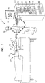
Fig. 1 is a schematic illustration of an invasive medical procedure using apparatus; -
Fig. 2 is a schematic perspective view of a balloon catheter in its inflated state; -
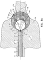
Figs. 3A-B are schematic sectional illustrations of a balloon catheter in its inflated state; and -
Fig. 4 is an illustration of simulated increased FOV half-angle; - Balloon catheters used for ablation of tissue, such as cardiac tissue, may be equipped with a camera inside the balloon. The camera is typically positioned at the proximal side of the balloon, with the axis of symmetry of its field of view (FOV) pointing to the distal side of the balloon. The image collected by the camera through the transparent areas of the walls of the balloon may be used to assess the degree of contact between the balloon and the cardiac tissue, and to turn off electrodes that are not in contact with the tissue. In case the balloon is used, for example, for the ablation of the ostium of a pulmonary vein, the degree to which the balloon seals off the vein may be verified by injecting a contrast agent in the vein upstream from the balloon. A rapid flow of the contrast agent past the balloon is an indication of poor sealing, and the images captured by the camera may be used to assess the flow of the contrast agent and thus the degree of sealing. Further, the images captured by the camera will yield information on the surface properties of the cardiac tissue.
- A drawback of cameras available for imaging through the balloon is their limited FOV. Embodiments of the present invention address this drawback by providing an apparatus that comprises a probe having a lumen, and a first inflatable transparent balloon which is deployable through the lumen. The first balloon is coupled to be filled with liquid. The apparatus also comprises a second inflatable transparent balloon which is deployable through the lumen, and which is disposed inside the first inflatable balloon at a proximal side of the first inflatable balloon. The second balloon is coupled to be filled with air. The apparatus further comprises a camera which is deployable through the lumen at the proximal side of the first inflatable balloon and which is configured to capture an optical image formed through the first and second inflatable balloons.
-
Fig. 1 is a schematic illustration of an invasive medicalprocedure using apparatus 12. The procedure is performed by amedical professional 14, and, by way of example, the procedure in the description hereinbelow is assumed to comprise ablation of a portion of a myocardium of aheart 16 of ahuman patient 18. However, it will be understood that the apparatus can be used in any procedure on biological tissue or on non-biological material. - In order to perform the ablation, professional 14 inserts a
probe 20 into asheath 21 that has been pre-positioned in a lumen ofpatient 18. Sheath 21 is positioned so that adistal end 22 of the probe enters the heart of the patient. Aballoon catheter 24 equipped with acamera 27, which is described in more detail below with reference toFigs. 2-3 , is deployed through alumen 23 ofprobe 20, and exits from the distal end of the probe. -
Apparatus 12 is controlled by aprocessor 46, which is located in anoperating console 48 of the apparatus.Console 48 comprisescontrols 49 which are used by professional 14 to communicate withprocessor 46. During the procedure,processor 46 typically tracks a location and an orientation ofdistal end 22 of the probe, using any method known in the art. For example,processor 46 may use a magnetic tracking method, wherein magnetic transmitters external topatient 18 generate signals in coils positioned indistal end 22. The Carto® system produced by Biosense Webster, of Diamond Bar, CA, uses such a tracking method. - The software for
processor 46 may be downloaded to the processor in electronic form, over a network, for example. Alternatively or additionally, the software may be provided on non-transitory tangible media, such as optical, magnetic, or electronic storage media. - Professional 14 may use
controls 49 to present animage 60, produced bycamera 27, on ascreen 62. - In order to operate
apparatus 12,processor 46 communicates withelectronics 50, which have a number of modules used by the processor to operate the apparatus. Thus,electronics 50 comprise anablation module 54 for controlling ablation power applied, and an electrocardiograph (ECG)module 56 for acquiring electrical signals generated inheart 16.Electronics 50 also comprise acamera module 57, which typically powerscamera 27 and which also receives images from the camera, and an inflation/deflation module 58 for inflating and deflating the balloons inballoon catheter 24.Electronics 50 typically comprise other modules, such as a force module for measuring the force ondistal end 22, a tracking module for operating the tracking method used byprocessor 46, and an irrigation module allowing the processor to control irrigation provided fordistal end 22. For simplicity, such other modules are not illustrated inFig. 1 . The modules may comprise hardware as well as software elements. -
Figs. 2 ,3A and3B are a schematic perspective view and two schematic sectional views, respectively, ofballoon catheter 24 in its inflated state.Figs. 3A-B show two configurations of the present invention, as will be described below. Ifballoon catheter 24 is used to ablate the ostium of a lumen, such as the pulmonary vein,balloon catheter 24 is supported by atubular shaft 70 having aproximal shaft portion 82.Shaft 70 comprises a hollowcentral tube 74, which permits aguidewire 29, withcamera 27 fixed at adistal end 28 of the guidewire, to traverse the tube. -
Balloon catheter 24 comprises two balloons: afirst balloon 80 sealed toshaft 70, and asecond balloon 83 inside the first balloon, disposed at aproximal side 90 offirst balloon 80 and sealed totube 74. Both balloons are bio-compatible and are typically formed from a plastic such as polyurethane (PU), which is transparent to optical radiation. In operationfirst balloon 80 andsecond balloon 83 may be deployed, in an uninflated state, vialumen 23 ofprobe 20, and after exiting fromdistal end 22, the balloons may be inflated.First balloon 80 has anexternal wall 81, over which generallysimilar electrodes 84 are typically attached by biocompatible cement. Conductiveproximal elements 86 ofelectrodes 84 are coupled toproximal shaft portion 82, and are used byablation module 54 to provide ablation power to the electrodes.First balloon 80 andelectrodes 84 typically have irrigation holes penetrating the balloon and the electrodes, but for simplicity such holes are not shown inFigs. 2 ,3A and3B . The parts ofexternal wall 81 offirst balloon 80 that are not covered byelectrodes 84 providecamera 27 with transparent windows through which the camera may collect images from outside the first balloon. - Typical steps leading to the initiation of an ablation procedure on a pulmonary vein utilizing
balloon catheter 24 are as follows: a distal end ofsheath 21 is positioned in aleft atrium 100 of the heart ofhuman patient 18, and probe 22 is inserted to the distal end of the sheath.Shaft 70 is inserted intoprobe 22 and the probe is guided until the distal end of the shaft is in proximity to the vein.Shaft 70 withballoon catheter 24 is then pushed out ofprobe 22 andfirst balloon 80 andsecond balloon 83 are inflated.First balloon 80 is inflated by filling it with a liquid 106 such as saline solution, andsecond balloon 83 is inflated by filling it withair 108. As shown inFig. 3A , at this pointproximal side 90 offirst balloon 80 and aproximal side 91 ofsecond balloon 83 are coincident.Guidewire 29, together withcamera 27 fixed todistal end 28 of the guidewire, is pushed intube 74 until the camera reachesproximal side 90 offirst balloon 80. - When the camera is in place, the inflated balloons and the camera may be pushed further until
first balloon 80 contacts anostium 102 of apulmonary vein 104. At this stage,camera module 57 may present images of the ostium acquired bycamera 27 onscreen 62, enabling professional 14 to determine a degree of contact of the first balloon, and its attachedelectrodes 84, with the ostium. If necessary, using the images acquired bycamera 27, professional 14 may adjust the position offirst balloon 80 to achieve satisfactory contact, i.e., have a high degree of contact, of the electrodes with the ostium. - Once professional 14 decides that
electrodes 84 are in contact withostium 102, ablation may be initiated. In some cases, the images acquired bycamera 27 may indicate to professional 14 that some ofelectrodes 84 are not in satisfactory contact with the ostium, i.e., have a low degree of contact, and in such an event the professional may decide not to ablate with these electrodes. - The schematic sectional illustration of
Fig. 3A is utilized to show the effect ofsecond balloon 83 on the capture of optical images bycamera 27 throughballoons proximal sides balloons camera 27 is located at the common proximal sides of the two balloons. Althoughfirst balloon 80 is shown inFig. 3A with a spherical shape, it may be deformed to a non-spherical shape by being pushed againstostium 102, thus reducing its dimensions from its typical diameter of 28 mm - 32 mm. However, in an embodiment of the present invention the diameter ofsecond balloon 83 may be selected to be sufficiently small, typically 20 mm - 26 mm, so that it will retain its spherical shape even withfirst balloon 80 deformed by external forces. - The impact of the refraction of optical rays at the air/liquid transition at the surface of
second balloon 83 is schematically illustrated by tracing a maximalchief ray 110, originating incamera 27. Herein "chief ray" means a ray that passes through the aperture stop ofcamera 27, and "maximal" indicates that an angle α thatchief ray 110 forms with anoptical axis 112 is the largest possible chief ray angle for the camera. Thus angle α is the half-angle of the FOV ofcamera 27.Optical axis 112 is defined bycamera 27 andsecond balloon 83 as their joint axis of symmetry. Following common practice in geometrical optics,chief ray 110 is traced outwards from the camera.Chief ray 110 impinges on the surface ofsecond balloon 83 at apoint 114, and refracts at that point to aray 116.Ray 116 forms an angle β with aline 118 that is parallel tooptical axis 112, propagates next inliquid 106 to apoint 120 onfirst balloon 80, and from there toostium 102. There is no further significant refraction ofray 116 when it passes acrosswall 81 offirst balloon 80, as the refractive index of the blood (or possibly contrast agent) outsidefirst balloon 80 is close to that ofliquid 106. The walls of both balloons are sufficiently thin, typically 20 µm - 100 µm, so that the effect of the walls on the optical rays traversing these walls may be neglected. - If
second balloon 83 were not deployed, and if the maximal chief ray angle ofcamera 27 is still α,ray 110 would propagate to apoint 122 as shown by a dottedline 124, andcamera 27 would have a smaller FOV half-angle of α instead of β. -
Fig. 3B shows a schematic sectional illustration ofballoon catheter 24 in its inflated state. Apart from the differences described below, the schematic sectional illustration shown inFig. 3B is generally similar to the schematic sectional illustration shown inFig. 3A , and elements indicated by the same reference numerals in bothFigs. 3A and3B are generally similar in construction and in operation. Infigure 3B , guidewire 29 and attachedcamera 27 are pushed further intosecond balloon 83, andsecond balloon 83 is pushed further intofirst balloon 80. While this repositioning reduces the FOV of the camera from the value achieved whencamera 27 is located atproximal side 91 ofsecond balloon 83, there is a corresponding increase of the magnification ofcamera 27.Fig. 3B showscamera 27 positioned at (or near)center 126 ofsecond balloon 83, while the second balloon is positioned so that adistal side 92 offirst balloon 80 and adistal side 93 ofsecond balloon 83 are coincident. -
Chief ray 100 again impinges on the surface ofsecond balloon 83 at apoint 114, and exits from the second balloon asray 116. However, due to the fact thatcamera 27 is located atcenter 126 ofsecond balloon 83, no (or very little) refraction takes place atpoint 114, and half-angle β is practically equal to half-angle α.Ray 116 propagates next a very short distance inliquid 106 to apoint 120 onfirst balloon 80, which practically coincides withpoint 114, and from there topoint 120 onpulmonary vein 104. Positioningcamera 27 further intosecond balloon 83 has decreased the FOV of the camera (increased its magnification), and positioning the second balloon towardsdistal side 92 offirst balloon 80 has moved the area imaged tocamera 27 deeper intopulmonary vein 104. - From consideration of
Figs. 3A and3B it will be understood thatcamera 27 can be repositioned to various locations withinsecond balloon 83, and thatsecond balloon 83 can be repositioned to various locations withinfirst balloon 80, and thatFig. 3A andFig. 3B illustrate but two possible locations for the camera and the two balloons. Thus, repositioning ofcamera 27 withinsecond balloon 83, and repositioning ofsecond balloon 83 withinfirst balloon 80, provide the ability to adjust both the FOV of the camera (and its magnification) and the images formed by the camera in a continuous fashion. -
Fig. 4 shows a graph of simulated increased FOV half-angle β vs. an initial half-angle α. The graph refers to the relative positioning ofballoons camera 27 as shown inFig. 3A . Angle β has been calculated analytically as a function of FOV half-angle α atcamera 27 withsecond balloon 83 deployed and filled with air, using a refractive index of 1.33 forliquid 106 fillingfirst balloon 80. An aperture stop ofcamera 27, and thus the origin ofray 110, are at the intersection ofoptical axis 112 andsecond balloon 83, the triangle formed by the origin ofray 110,point 114 and acenter point 126 ofsecond balloon 83 is an isosceles triangle. Consequently, the angle of incidence of distal end ofray 110 onsecond balloon 83 is also α, and angle β is independent of the diameter ofsecond balloon 83 as long the spherical shape of second balloon is not affected by a deformation offirst balloon 80.Curves 130 show both the increased FOV half-angle β as acurve 132 and the increase β-α of the FOV half-angle as acurve 134, both as a function of the initial FOV half-angle α atcamera 27. For an initial FOV half-angle α= 45°, the increased FOV half-angle is β = 57.9°, with an increase of β-α = 12.9°. For an initial FOV half-angle α = 60°, the increased FOV half-angle is β = 79.4°, with an increase of β-α = 19.4°. - It will be understood that the increase in field of view described above is effected by the optical surface, provided by the second balloon, which separates the air in the second balloon from the liquid of the first balloon.
- It will be appreciated that the embodiments described above are cited by way of example, and that the present invention is not limited to what has been particularly shown and described hereinabove. Rather, the scope of the present invention is defined by the claims.
Claims (4)
- Apparatus (12), comprising:a probe (20) having a lumen (23);a first inflatable transparent balloon (80) deployable through the lumen and coupled to be filled with liquid;a second inflatable transparent balloon (83) deployable through the lumen, disposed inside the first inflatable balloon between a proximal side and a distal side of the first inflatable balloon, and coupled to be filled with air; anda camera (27) deployable through the lumen between a proximal side and a distal side of the second inflatable balloon and configured to capture an optical image formed through the first and second inflatable balloons,wherein the camera (27) is configured to be repositionable within the second inflatable balloon (83), and the second inflatable balloon (83) is configured to be repositionable within the first inflatable balloon (80), thereby to adjust a field of view and magnification of the camera (27) and thereby the optical image captured by the camera (27).
- The apparatus (12) according to claim 1, wherein the first (80) and second (83) inflatable transparent balloons are configured for deployment inside a heart.
- The apparatus (12) according to claim 1, wherein the first inflatable transparent balloon (80) is partially covered with a multiplicity of electrodes (84) that are configured for cardiac ablation.
- The apparatus (12) according to claim 1, wherein a diameter of the first inflatable transparent balloon (80) is in a range 28 mm - 32 mm, and a diameter of the second inflatable transparent balloon (83) is in a range 20 mm - 26 mm.
Priority Applications (1)
| Application Number | Priority Date | Filing Date | Title |
|---|---|---|---|
| EP19197531.7A EP3603556A1 (en) | 2017-02-28 | 2018-02-27 | Lens in balloon catheter |
Applications Claiming Priority (1)
| Application Number | Priority Date | Filing Date | Title |
|---|---|---|---|
| US15/444,521 US20180242821A1 (en) | 2017-02-28 | 2017-02-28 | Lens in balloon catheter |
Related Child Applications (1)
| Application Number | Title | Priority Date | Filing Date |
|---|---|---|---|
| EP19197531.7A Division EP3603556A1 (en) | 2017-02-28 | 2018-02-27 | Lens in balloon catheter |
Publications (2)
| Publication Number | Publication Date |
|---|---|
| EP3366249A1 EP3366249A1 (en) | 2018-08-29 |
| EP3366249B1 true EP3366249B1 (en) | 2019-10-16 |
Family
ID=61563127
Family Applications (2)
| Application Number | Title | Priority Date | Filing Date |
|---|---|---|---|
| EP18158811.2A Active EP3366249B1 (en) | 2017-02-28 | 2018-02-27 | Lens in balloon catheter |
| EP19197531.7A Withdrawn EP3603556A1 (en) | 2017-02-28 | 2018-02-27 | Lens in balloon catheter |
Family Applications After (1)
| Application Number | Title | Priority Date | Filing Date |
|---|---|---|---|
| EP19197531.7A Withdrawn EP3603556A1 (en) | 2017-02-28 | 2018-02-27 | Lens in balloon catheter |
Country Status (8)
| Country | Link |
|---|---|
| US (1) | US20180242821A1 (en) |
| EP (2) | EP3366249B1 (en) |
| JP (1) | JP2018140173A (en) |
| CN (1) | CN108523824A (en) |
| AU (1) | AU2018201223A1 (en) |
| CA (1) | CA2995294A1 (en) |
| ES (1) | ES2763809T3 (en) |
| IL (1) | IL257585B (en) |
Families Citing this family (3)
| Publication number | Priority date | Publication date | Assignee | Title |
|---|---|---|---|---|
| WO2020197979A1 (en) * | 2019-03-22 | 2020-10-01 | Boston Scientific Scimed Inc | Automated electrode recommendation for ablation systems |
| US20210001093A1 (en) * | 2019-07-02 | 2021-01-07 | Biosense Webster (Israel) Ltd. | Moving a guidewire in a brain lumen |
| EP4178414A2 (en) * | 2020-07-08 | 2023-05-17 | PROCEPT BioRobotics Corporation | Hemostasis methods and apparatuses |
Citations (4)
| Publication number | Priority date | Publication date | Assignee | Title |
|---|---|---|---|---|
| US20060135961A1 (en) * | 2004-12-17 | 2006-06-22 | Biocardia, Inc. | Steerable guide catheters and methods for their use |
| US20080115793A1 (en) * | 2006-11-21 | 2008-05-22 | Roschak Edmund J | Methods and devices for accessing the heart |
| US20100256629A1 (en) * | 2009-04-06 | 2010-10-07 | Voyage Medical, Inc. | Methods and devices for treatment of the ostium |
| US20130165769A1 (en) * | 2011-03-01 | 2013-06-27 | Lawrence J. Gerrans | Nested balloon catheter for localized drug delivery |
Family Cites Families (22)
| Publication number | Priority date | Publication date | Assignee | Title |
|---|---|---|---|---|
| US5632761A (en) * | 1991-05-29 | 1997-05-27 | Origin Medsystems, Inc. | Inflatable devices for separating layers of tissue, and methods of using |
| US6231595B1 (en) * | 1998-03-31 | 2001-05-15 | Innercool Therapies, Inc. | Circulating fluid hypothermia method and apparatus |
| US7291144B2 (en) * | 1998-03-31 | 2007-11-06 | Innercool Therapies, Inc. | Method and device for performing cooling- or cryo-therapies for, e.g., angioplasty with reduced restenosis or pulmonary vein cell necrosis to inhibit atrial fibrillation |
| US6532387B1 (en) | 1999-03-26 | 2003-03-11 | Kevin S. Marchitto | Catheter for delivering electromagnetic energy for enhanced permeation of substances |
| WO2002005868A2 (en) | 2000-07-13 | 2002-01-24 | Transurgical, Inc. | Thermal treatment methods and apparatus with focused energy application |
| US20020068885A1 (en) | 2000-07-13 | 2002-06-06 | Harhen Edward Paul | Energy application with inflatable annular lens |
| JP2005531336A (en) | 2002-04-02 | 2005-10-20 | ルマークス、インコーポレイテッド | Device and method using visible light to weaken and / or kill microorganisms in the body |
| US20050049509A1 (en) * | 2003-08-28 | 2005-03-03 | Mansour Hebah Noshy | Cervix monitoring system and related devices and methods |
| US20060155269A1 (en) | 2005-01-12 | 2006-07-13 | Prorhythm, Inc. | Epicardial ablation using focused ultrasound |
| DE102005005933A1 (en) | 2005-02-09 | 2006-08-17 | Carl Zeiss Meditec Ag | Variable optics |
| JP4892102B2 (en) | 2007-07-11 | 2012-03-07 | コーニンクレッカ フィリップス エレクトロニクス エヌ ヴィ | Ultrasonic assembly with adjustable fluid lens |
| US20090062790A1 (en) * | 2007-08-31 | 2009-03-05 | Voyage Medical, Inc. | Direct visualization bipolar ablation systems |
| WO2009140066A1 (en) * | 2008-05-12 | 2009-11-19 | Boston Scientific Scimed, Inc. | Apparatus for chilling cryo-ablation coolant |
| US8136942B2 (en) | 2009-10-14 | 2012-03-20 | Adlens Beacon, Inc. | Aspheric fluid filled lens optic |
| CN104066368B (en) * | 2011-09-22 | 2017-02-22 | 乔治华盛顿大学 | Systems and methods for visualizing ablated tissue |
| US9345864B2 (en) * | 2013-03-15 | 2016-05-24 | Terumo Kabushiki Kaisha | Methods for treating sinus ostia using balloon catheter devices having a slidable balloon portion |
| KR20150140760A (en) * | 2013-04-08 | 2015-12-16 | 아파마 메디칼, 인크. | Cardiac ablation catheters and methods of use thereof |
| US10441338B2 (en) * | 2014-01-14 | 2019-10-15 | Medtronic Cryocath Lp | Balloon catheter with fluid injection elements |
| US9855089B2 (en) * | 2014-03-21 | 2018-01-02 | Medtronic Cryocath Lp | Shape changing ablation balloon |
| US9925359B2 (en) * | 2014-03-21 | 2018-03-27 | Medtronic Cryocath Lp | Balloon design to reduce distal length |
| US9844641B2 (en) * | 2014-07-16 | 2017-12-19 | Fractyl Laboratories, Inc. | Systems, devices and methods for performing medical procedures in the intestine |
| CN204839438U (en) * | 2015-05-25 | 2015-12-09 | 黄冰生 | Head end has angioscope of sacculus |
-
2017
- 2017-02-28 US US15/444,521 patent/US20180242821A1/en not_active Abandoned
-
2018
- 2018-02-15 CA CA2995294A patent/CA2995294A1/en not_active Abandoned
- 2018-02-18 IL IL257585A patent/IL257585B/en active IP Right Grant
- 2018-02-20 AU AU2018201223A patent/AU2018201223A1/en not_active Abandoned
- 2018-02-27 ES ES18158811T patent/ES2763809T3/en active Active
- 2018-02-27 EP EP18158811.2A patent/EP3366249B1/en active Active
- 2018-02-27 JP JP2018033027A patent/JP2018140173A/en not_active Abandoned
- 2018-02-27 EP EP19197531.7A patent/EP3603556A1/en not_active Withdrawn
- 2018-02-28 CN CN201810170443.3A patent/CN108523824A/en active Pending
Patent Citations (4)
| Publication number | Priority date | Publication date | Assignee | Title |
|---|---|---|---|---|
| US20060135961A1 (en) * | 2004-12-17 | 2006-06-22 | Biocardia, Inc. | Steerable guide catheters and methods for their use |
| US20080115793A1 (en) * | 2006-11-21 | 2008-05-22 | Roschak Edmund J | Methods and devices for accessing the heart |
| US20100256629A1 (en) * | 2009-04-06 | 2010-10-07 | Voyage Medical, Inc. | Methods and devices for treatment of the ostium |
| US20130165769A1 (en) * | 2011-03-01 | 2013-06-27 | Lawrence J. Gerrans | Nested balloon catheter for localized drug delivery |
Also Published As
| Publication number | Publication date |
|---|---|
| CA2995294A1 (en) | 2018-08-28 |
| JP2018140173A (en) | 2018-09-13 |
| EP3366249A1 (en) | 2018-08-29 |
| AU2018201223A1 (en) | 2018-09-13 |
| IL257585A (en) | 2018-04-30 |
| ES2763809T3 (en) | 2020-06-01 |
| US20180242821A1 (en) | 2018-08-30 |
| EP3603556A1 (en) | 2020-02-05 |
| CN108523824A (en) | 2018-09-14 |
| IL257585B (en) | 2021-04-29 |
Similar Documents
| Publication | Publication Date | Title |
|---|---|---|
| US11633213B2 (en) | Catheter systems with imaging assemblies | |
| US11889982B2 (en) | Electrophysiology mapping and visualization system | |
| US6979290B2 (en) | Apparatus and methods for coronary sinus access | |
| JP4780678B2 (en) | Body fluid blocking device | |
| US11813419B2 (en) | Double balloon catheter having a lobed inner balloon | |
| US7837676B2 (en) | Cardiac ablation devices | |
| JP5065052B2 (en) | Flexible sheath catheter | |
| US8934962B2 (en) | Electrophysiology mapping and visualization system | |
| EP3366249B1 (en) | Lens in balloon catheter | |
| US11963715B2 (en) | Balloon-in-balloon irrigation balloon catheter | |
| US20140114304A1 (en) | Ablation catheter system and method for deploying same |
Legal Events
| Date | Code | Title | Description |
|---|---|---|---|
| PUAI | Public reference made under article 153(3) epc to a published international application that has entered the european phase |
Free format text: ORIGINAL CODE: 0009012 |
|
| STAA | Information on the status of an ep patent application or granted ep patent |
Free format text: STATUS: THE APPLICATION HAS BEEN PUBLISHED |
|
| AK | Designated contracting states |
Kind code of ref document: A1 Designated state(s): AL AT BE BG CH CY CZ DE DK EE ES FI FR GB GR HR HU IE IS IT LI LT LU LV MC MK MT NL NO PL PT RO RS SE SI SK SM TR |
|
| AX | Request for extension of the european patent |
Extension state: BA ME |
|
| STAA | Information on the status of an ep patent application or granted ep patent |
Free format text: STATUS: REQUEST FOR EXAMINATION WAS MADE |
|
| 17P | Request for examination filed |
Effective date: 20180918 |
|
| RBV | Designated contracting states (corrected) |
Designated state(s): AL AT BE BG CH CY CZ DE DK EE ES FI FR GB GR HR HU IE IS IT LI LT LU LV MC MK MT NL NO PL PT RO RS SE SI SK SM TR |
|
| STAA | Information on the status of an ep patent application or granted ep patent |
Free format text: STATUS: EXAMINATION IS IN PROGRESS |
|
| 17Q | First examination report despatched |
Effective date: 20181025 |
|
| GRAP | Despatch of communication of intention to grant a patent |
Free format text: ORIGINAL CODE: EPIDOSNIGR1 |
|
| STAA | Information on the status of an ep patent application or granted ep patent |
Free format text: STATUS: GRANT OF PATENT IS INTENDED |
|
| INTG | Intention to grant announced |
Effective date: 20190426 |
|
| GRAS | Grant fee paid |
Free format text: ORIGINAL CODE: EPIDOSNIGR3 |
|
| GRAA | (expected) grant |
Free format text: ORIGINAL CODE: 0009210 |
|
| STAA | Information on the status of an ep patent application or granted ep patent |
Free format text: STATUS: THE PATENT HAS BEEN GRANTED |
|
| AK | Designated contracting states |
Kind code of ref document: B1 Designated state(s): AL AT BE BG CH CY CZ DE DK EE ES FI FR GB GR HR HU IE IS IT LI LT LU LV MC MK MT NL NO PL PT RO RS SE SI SK SM TR |
|
| REG | Reference to a national code |
Ref country code: GB Ref legal event code: FG4D |
|
| REG | Reference to a national code |
Ref country code: CH Ref legal event code: EP Ref country code: CH Ref legal event code: NV Representative=s name: E. BLUM AND CO. AG PATENT- UND MARKENANWAELTE , CH |
|
| REG | Reference to a national code |
Ref country code: DE Ref legal event code: R096 Ref document number: 602018000866 Country of ref document: DE |
|
| REG | Reference to a national code |
Ref country code: IE Ref legal event code: FG4D |
|
| REG | Reference to a national code |
Ref country code: AT Ref legal event code: REF Ref document number: 1190537 Country of ref document: AT Kind code of ref document: T Effective date: 20191115 |
|
| REG | Reference to a national code |
Ref country code: NL Ref legal event code: FP |
|
| REG | Reference to a national code |
Ref country code: LT Ref legal event code: MG4D |
|
| REG | Reference to a national code |
Ref country code: AT Ref legal event code: MK05 Ref document number: 1190537 Country of ref document: AT Kind code of ref document: T Effective date: 20191016 |
|
| PG25 | Lapsed in a contracting state [announced via postgrant information from national office to epo] |
Ref country code: LV Free format text: LAPSE BECAUSE OF FAILURE TO SUBMIT A TRANSLATION OF THE DESCRIPTION OR TO PAY THE FEE WITHIN THE PRESCRIBED TIME-LIMIT Effective date: 20191016 Ref country code: SE Free format text: LAPSE BECAUSE OF FAILURE TO SUBMIT A TRANSLATION OF THE DESCRIPTION OR TO PAY THE FEE WITHIN THE PRESCRIBED TIME-LIMIT Effective date: 20191016 Ref country code: AT Free format text: LAPSE BECAUSE OF FAILURE TO SUBMIT A TRANSLATION OF THE DESCRIPTION OR TO PAY THE FEE WITHIN THE PRESCRIBED TIME-LIMIT Effective date: 20191016 Ref country code: PL Free format text: LAPSE BECAUSE OF FAILURE TO SUBMIT A TRANSLATION OF THE DESCRIPTION OR TO PAY THE FEE WITHIN THE PRESCRIBED TIME-LIMIT Effective date: 20191016 Ref country code: LT Free format text: LAPSE BECAUSE OF FAILURE TO SUBMIT A TRANSLATION OF THE DESCRIPTION OR TO PAY THE FEE WITHIN THE PRESCRIBED TIME-LIMIT Effective date: 20191016 Ref country code: GR Free format text: LAPSE BECAUSE OF FAILURE TO SUBMIT A TRANSLATION OF THE DESCRIPTION OR TO PAY THE FEE WITHIN THE PRESCRIBED TIME-LIMIT Effective date: 20200117 Ref country code: NO Free format text: LAPSE BECAUSE OF FAILURE TO SUBMIT A TRANSLATION OF THE DESCRIPTION OR TO PAY THE FEE WITHIN THE PRESCRIBED TIME-LIMIT Effective date: 20200116 Ref country code: BG Free format text: LAPSE BECAUSE OF FAILURE TO SUBMIT A TRANSLATION OF THE DESCRIPTION OR TO PAY THE FEE WITHIN THE PRESCRIBED TIME-LIMIT Effective date: 20200116 Ref country code: FI Free format text: LAPSE BECAUSE OF FAILURE TO SUBMIT A TRANSLATION OF THE DESCRIPTION OR TO PAY THE FEE WITHIN THE PRESCRIBED TIME-LIMIT Effective date: 20191016 Ref country code: PT Free format text: LAPSE BECAUSE OF FAILURE TO SUBMIT A TRANSLATION OF THE DESCRIPTION OR TO PAY THE FEE WITHIN THE PRESCRIBED TIME-LIMIT Effective date: 20200217 |
|
| PGFP | Annual fee paid to national office [announced via postgrant information from national office to epo] |
Ref country code: ES Payment date: 20200302 Year of fee payment: 3 Ref country code: IE Payment date: 20200210 Year of fee payment: 3 |
|
| PG25 | Lapsed in a contracting state [announced via postgrant information from national office to epo] |
Ref country code: RS Free format text: LAPSE BECAUSE OF FAILURE TO SUBMIT A TRANSLATION OF THE DESCRIPTION OR TO PAY THE FEE WITHIN THE PRESCRIBED TIME-LIMIT Effective date: 20191016 Ref country code: IS Free format text: LAPSE BECAUSE OF FAILURE TO SUBMIT A TRANSLATION OF THE DESCRIPTION OR TO PAY THE FEE WITHIN THE PRESCRIBED TIME-LIMIT Effective date: 20200224 Ref country code: HR Free format text: LAPSE BECAUSE OF FAILURE TO SUBMIT A TRANSLATION OF THE DESCRIPTION OR TO PAY THE FEE WITHIN THE PRESCRIBED TIME-LIMIT Effective date: 20191016 |
|
| PGFP | Annual fee paid to national office [announced via postgrant information from national office to epo] |
Ref country code: BE Payment date: 20200114 Year of fee payment: 3 |
|
| REG | Reference to a national code |
Ref country code: ES Ref legal event code: FG2A Ref document number: 2763809 Country of ref document: ES Kind code of ref document: T3 Effective date: 20200601 |
|
| PG25 | Lapsed in a contracting state [announced via postgrant information from national office to epo] |
Ref country code: AL Free format text: LAPSE BECAUSE OF FAILURE TO SUBMIT A TRANSLATION OF THE DESCRIPTION OR TO PAY THE FEE WITHIN THE PRESCRIBED TIME-LIMIT Effective date: 20191016 |
|
| REG | Reference to a national code |
Ref country code: DE Ref legal event code: R097 Ref document number: 602018000866 Country of ref document: DE |
|
| PG2D | Information on lapse in contracting state deleted |
Ref country code: IS |
|
| PG25 | Lapsed in a contracting state [announced via postgrant information from national office to epo] |
Ref country code: DK Free format text: LAPSE BECAUSE OF FAILURE TO SUBMIT A TRANSLATION OF THE DESCRIPTION OR TO PAY THE FEE WITHIN THE PRESCRIBED TIME-LIMIT Effective date: 20191016 Ref country code: EE Free format text: LAPSE BECAUSE OF FAILURE TO SUBMIT A TRANSLATION OF THE DESCRIPTION OR TO PAY THE FEE WITHIN THE PRESCRIBED TIME-LIMIT Effective date: 20191016 Ref country code: CZ Free format text: LAPSE BECAUSE OF FAILURE TO SUBMIT A TRANSLATION OF THE DESCRIPTION OR TO PAY THE FEE WITHIN THE PRESCRIBED TIME-LIMIT Effective date: 20191016 Ref country code: RO Free format text: LAPSE BECAUSE OF FAILURE TO SUBMIT A TRANSLATION OF THE DESCRIPTION OR TO PAY THE FEE WITHIN THE PRESCRIBED TIME-LIMIT Effective date: 20191016 Ref country code: IS Free format text: LAPSE BECAUSE OF FAILURE TO SUBMIT A TRANSLATION OF THE DESCRIPTION OR TO PAY THE FEE WITHIN THE PRESCRIBED TIME-LIMIT Effective date: 20200216 |
|
| PLBE | No opposition filed within time limit |
Free format text: ORIGINAL CODE: 0009261 |
|
| STAA | Information on the status of an ep patent application or granted ep patent |
Free format text: STATUS: NO OPPOSITION FILED WITHIN TIME LIMIT |
|
| PG25 | Lapsed in a contracting state [announced via postgrant information from national office to epo] |
Ref country code: SM Free format text: LAPSE BECAUSE OF FAILURE TO SUBMIT A TRANSLATION OF THE DESCRIPTION OR TO PAY THE FEE WITHIN THE PRESCRIBED TIME-LIMIT Effective date: 20191016 Ref country code: SK Free format text: LAPSE BECAUSE OF FAILURE TO SUBMIT A TRANSLATION OF THE DESCRIPTION OR TO PAY THE FEE WITHIN THE PRESCRIBED TIME-LIMIT Effective date: 20191016 |
|
| 26N | No opposition filed |
Effective date: 20200717 |
|
| PG25 | Lapsed in a contracting state [announced via postgrant information from national office to epo] |
Ref country code: MC Free format text: LAPSE BECAUSE OF FAILURE TO SUBMIT A TRANSLATION OF THE DESCRIPTION OR TO PAY THE FEE WITHIN THE PRESCRIBED TIME-LIMIT Effective date: 20191016 Ref country code: LU Free format text: LAPSE BECAUSE OF NON-PAYMENT OF DUE FEES Effective date: 20200227 |
|
| PG25 | Lapsed in a contracting state [announced via postgrant information from national office to epo] |
Ref country code: SI Free format text: LAPSE BECAUSE OF FAILURE TO SUBMIT A TRANSLATION OF THE DESCRIPTION OR TO PAY THE FEE WITHIN THE PRESCRIBED TIME-LIMIT Effective date: 20191016 |
|
| PGFP | Annual fee paid to national office [announced via postgrant information from national office to epo] |
Ref country code: FR Payment date: 20210112 Year of fee payment: 4 Ref country code: NL Payment date: 20210212 Year of fee payment: 4 Ref country code: IT Payment date: 20210228 Year of fee payment: 4 |
|
| PGFP | Annual fee paid to national office [announced via postgrant information from national office to epo] |
Ref country code: DE Payment date: 20210216 Year of fee payment: 4 |
|
| REG | Reference to a national code |
Ref country code: BE Ref legal event code: MM Effective date: 20210228 |
|
| PG25 | Lapsed in a contracting state [announced via postgrant information from national office to epo] |
Ref country code: CH Free format text: LAPSE BECAUSE OF NON-PAYMENT OF DUE FEES Effective date: 20210228 Ref country code: LI Free format text: LAPSE BECAUSE OF NON-PAYMENT OF DUE FEES Effective date: 20210228 |
|
| PG25 | Lapsed in a contracting state [announced via postgrant information from national office to epo] |
Ref country code: IE Free format text: LAPSE BECAUSE OF NON-PAYMENT OF DUE FEES Effective date: 20210227 |
|
| REG | Reference to a national code |
Ref country code: ES Ref legal event code: FD2A Effective date: 20220504 |
|
| PG25 | Lapsed in a contracting state [announced via postgrant information from national office to epo] |
Ref country code: TR Free format text: LAPSE BECAUSE OF FAILURE TO SUBMIT A TRANSLATION OF THE DESCRIPTION OR TO PAY THE FEE WITHIN THE PRESCRIBED TIME-LIMIT Effective date: 20191016 Ref country code: MT Free format text: LAPSE BECAUSE OF FAILURE TO SUBMIT A TRANSLATION OF THE DESCRIPTION OR TO PAY THE FEE WITHIN THE PRESCRIBED TIME-LIMIT Effective date: 20191016 Ref country code: CY Free format text: LAPSE BECAUSE OF FAILURE TO SUBMIT A TRANSLATION OF THE DESCRIPTION OR TO PAY THE FEE WITHIN THE PRESCRIBED TIME-LIMIT Effective date: 20191016 |
|
| PG25 | Lapsed in a contracting state [announced via postgrant information from national office to epo] |
Ref country code: MK Free format text: LAPSE BECAUSE OF FAILURE TO SUBMIT A TRANSLATION OF THE DESCRIPTION OR TO PAY THE FEE WITHIN THE PRESCRIBED TIME-LIMIT Effective date: 20191016 |
|
| PG25 | Lapsed in a contracting state [announced via postgrant information from national office to epo] |
Ref country code: ES Free format text: LAPSE BECAUSE OF NON-PAYMENT OF DUE FEES Effective date: 20210228 Ref country code: BE Free format text: LAPSE BECAUSE OF NON-PAYMENT OF DUE FEES Effective date: 20210228 |
|
| REG | Reference to a national code |
Ref country code: DE Ref legal event code: R119 Ref document number: 602018000866 Country of ref document: DE |
|
| REG | Reference to a national code |
Ref country code: NL Ref legal event code: MM Effective date: 20220301 |
|
| GBPC | Gb: european patent ceased through non-payment of renewal fee |
Effective date: 20220227 |
|
| PG25 | Lapsed in a contracting state [announced via postgrant information from national office to epo] |
Ref country code: NL Free format text: LAPSE BECAUSE OF NON-PAYMENT OF DUE FEES Effective date: 20220301 Ref country code: FR Free format text: LAPSE BECAUSE OF NON-PAYMENT OF DUE FEES Effective date: 20220228 |
|
| PG25 | Lapsed in a contracting state [announced via postgrant information from national office to epo] |
Ref country code: GB Free format text: LAPSE BECAUSE OF NON-PAYMENT OF DUE FEES Effective date: 20220227 Ref country code: DE Free format text: LAPSE BECAUSE OF NON-PAYMENT OF DUE FEES Effective date: 20220901 |
|
| PG25 | Lapsed in a contracting state [announced via postgrant information from national office to epo] |
Ref country code: IT Free format text: LAPSE BECAUSE OF NON-PAYMENT OF DUE FEES Effective date: 20220227 |