EP3366239A1 - Intravascular catheter having an expandable incising portion and abrasive surfaces - Google Patents
Intravascular catheter having an expandable incising portion and abrasive surfaces Download PDFInfo
- Publication number
- EP3366239A1 EP3366239A1 EP18158211.5A EP18158211A EP3366239A1 EP 3366239 A1 EP3366239 A1 EP 3366239A1 EP 18158211 A EP18158211 A EP 18158211A EP 3366239 A1 EP3366239 A1 EP 3366239A1
- Authority
- EP
- European Patent Office
- Prior art keywords
- expandable portion
- struts
- catheter device
- intravascular catheter
- catheter tube
- Prior art date
- Legal status (The legal status is an assumption and is not a legal conclusion. Google has not performed a legal analysis and makes no representation as to the accuracy of the status listed.)
- Granted
Links
- 230000003143 atherosclerotic effect Effects 0.000 claims abstract description 44
- 239000000463 material Substances 0.000 claims abstract description 44
- 210000004204 blood vessel Anatomy 0.000 claims abstract description 37
- 230000001681 protective effect Effects 0.000 claims description 27
- 230000002792 vascular Effects 0.000 claims description 6
- 229910003460 diamond Inorganic materials 0.000 claims description 3
- 239000010432 diamond Substances 0.000 claims description 3
- 239000000428 dust Substances 0.000 claims description 3
- 239000000853 adhesive Substances 0.000 description 7
- 230000001070 adhesive effect Effects 0.000 description 7
- 239000010935 stainless steel Substances 0.000 description 7
- 229910001220 stainless steel Inorganic materials 0.000 description 7
- -1 but not limited to Substances 0.000 description 6
- 238000000034 method Methods 0.000 description 6
- 239000004698 Polyethylene Substances 0.000 description 5
- 238000002399 angioplasty Methods 0.000 description 5
- HLXZNVUGXRDIFK-UHFFFAOYSA-N nickel titanium Chemical compound [Ti].[Ti].[Ti].[Ti].[Ti].[Ti].[Ti].[Ti].[Ti].[Ti].[Ti].[Ni].[Ni].[Ni].[Ni].[Ni].[Ni].[Ni].[Ni].[Ni].[Ni].[Ni].[Ni].[Ni].[Ni] HLXZNVUGXRDIFK-UHFFFAOYSA-N 0.000 description 5
- 229910001000 nickel titanium Inorganic materials 0.000 description 5
- 229920000573 polyethylene Polymers 0.000 description 5
- 229920002554 vinyl polymer Polymers 0.000 description 5
- 201000001320 Atherosclerosis Diseases 0.000 description 4
- 238000005299 abrasion Methods 0.000 description 4
- 239000000560 biocompatible material Substances 0.000 description 4
- 230000000694 effects Effects 0.000 description 3
- 230000003902 lesion Effects 0.000 description 3
- 230000000007 visual effect Effects 0.000 description 3
- 208000007536 Thrombosis Diseases 0.000 description 2
- 238000004891 communication Methods 0.000 description 2
- 238000013467 fragmentation Methods 0.000 description 2
- 238000006062 fragmentation reaction Methods 0.000 description 2
- 238000003780 insertion Methods 0.000 description 2
- 230000037431 insertion Effects 0.000 description 2
- 239000000126 substance Substances 0.000 description 2
- 208000037260 Atherosclerotic Plaque Diseases 0.000 description 1
- 208000017667 Chronic Disease Diseases 0.000 description 1
- 229910000677 High-carbon steel Inorganic materials 0.000 description 1
- 229920002614 Polyether block amide Polymers 0.000 description 1
- 229910000831 Steel Inorganic materials 0.000 description 1
- 238000005452 bending Methods 0.000 description 1
- 230000015572 biosynthetic process Effects 0.000 description 1
- 230000017531 blood circulation Effects 0.000 description 1
- 210000000748 cardiovascular system Anatomy 0.000 description 1
- 239000000919 ceramic Substances 0.000 description 1
- 239000011248 coating agent Substances 0.000 description 1
- 238000000576 coating method Methods 0.000 description 1
- 230000003247 decreasing effect Effects 0.000 description 1
- 239000012634 fragment Substances 0.000 description 1
- 238000012978 minimally invasive surgical procedure Methods 0.000 description 1
- 238000012986 modification Methods 0.000 description 1
- 229920000642 polymer Polymers 0.000 description 1
- 239000012858 resilient material Substances 0.000 description 1
- 238000007788 roughening Methods 0.000 description 1
- 239000007787 solid Substances 0.000 description 1
- 239000010959 steel Substances 0.000 description 1
- 238000004381 surface treatment Methods 0.000 description 1
- 238000001356 surgical procedure Methods 0.000 description 1
Images


Classifications
-
- A—HUMAN NECESSITIES
- A61—MEDICAL OR VETERINARY SCIENCE; HYGIENE
- A61B—DIAGNOSIS; SURGERY; IDENTIFICATION
- A61B17/00—Surgical instruments, devices or methods, e.g. tourniquets
- A61B17/32—Surgical cutting instruments
- A61B17/3205—Excision instruments
- A61B17/3207—Atherectomy devices working by cutting or abrading; Similar devices specially adapted for non-vascular obstructions
- A61B17/320725—Atherectomy devices working by cutting or abrading; Similar devices specially adapted for non-vascular obstructions with radially expandable cutting or abrading elements
-
- A—HUMAN NECESSITIES
- A61—MEDICAL OR VETERINARY SCIENCE; HYGIENE
- A61B—DIAGNOSIS; SURGERY; IDENTIFICATION
- A61B17/00—Surgical instruments, devices or methods, e.g. tourniquets
- A61B17/32—Surgical cutting instruments
- A61B17/3209—Incision instruments
-
- A—HUMAN NECESSITIES
- A61—MEDICAL OR VETERINARY SCIENCE; HYGIENE
- A61B—DIAGNOSIS; SURGERY; IDENTIFICATION
- A61B17/00—Surgical instruments, devices or methods, e.g. tourniquets
- A61B17/32—Surgical cutting instruments
- A61B17/3205—Excision instruments
- A61B17/3207—Atherectomy devices working by cutting or abrading; Similar devices specially adapted for non-vascular obstructions
- A61B17/32075—Pullback cutting; combined forward and pullback cutting, e.g. with cutters at both sides of the plaque
-
- A—HUMAN NECESSITIES
- A61—MEDICAL OR VETERINARY SCIENCE; HYGIENE
- A61B—DIAGNOSIS; SURGERY; IDENTIFICATION
- A61B17/00—Surgical instruments, devices or methods, e.g. tourniquets
- A61B2017/00982—General structural features
- A61B2017/00986—Malecots, e.g. slotted tubes, of which the distal end is pulled to deflect side struts
-
- A—HUMAN NECESSITIES
- A61—MEDICAL OR VETERINARY SCIENCE; HYGIENE
- A61B—DIAGNOSIS; SURGERY; IDENTIFICATION
- A61B17/00—Surgical instruments, devices or methods, e.g. tourniquets
- A61B17/32—Surgical cutting instruments
- A61B2017/320004—Surgical cutting instruments abrasive
-
- A—HUMAN NECESSITIES
- A61—MEDICAL OR VETERINARY SCIENCE; HYGIENE
- A61B—DIAGNOSIS; SURGERY; IDENTIFICATION
- A61B90/00—Instruments, implements or accessories specially adapted for surgery or diagnosis and not covered by any of the groups A61B1/00 - A61B50/00, e.g. for luxation treatment or for protecting wound edges
- A61B90/06—Measuring instruments not otherwise provided for
- A61B2090/061—Measuring instruments not otherwise provided for for measuring dimensions, e.g. length
-
- A—HUMAN NECESSITIES
- A61—MEDICAL OR VETERINARY SCIENCE; HYGIENE
- A61B—DIAGNOSIS; SURGERY; IDENTIFICATION
- A61B90/00—Instruments, implements or accessories specially adapted for surgery or diagnosis and not covered by any of the groups A61B1/00 - A61B50/00, e.g. for luxation treatment or for protecting wound edges
- A61B90/08—Accessories or related features not otherwise provided for
- A61B2090/0807—Indication means
- A61B2090/0811—Indication means for the position of a particular part of an instrument with respect to the rest of the instrument, e.g. position of the anvil of a stapling instrument
Definitions
- This invention relates in general to intravascular catheters, such as can be used during minimally invasive surgical procedures.
- this invention relates to an intravascular catheter having an expandable incising portion.
- Atherosclerosis is a chronic condition in which atheromatous plaque accumulates on the inner walls of a blood vessel. As a result, the blood vessel walls can become inflamed and, over time, may harden to form atherosclerotic lesions that cause a narrowing of the vessel lumen. In severe cases, the atherosclerotic lesions can rupture and induce the formation of thrombus (i.e., blood clots), which can prevent blood flow through the narrowed vessel lumen.
- thrombus i.e., blood clots
- an angioplasty is a procedure in which a balloon catheter is inserted into a narrowed region of the vessel lumen via a delivery catheter.
- the balloon catheter includes a flexible tube having an inflatable balloon at an end thereof. Once positioned in the narrowed region, the balloon is inflated in order to dilate the narrowed vessel lumen.
- the pressure in the balloon is generally sufficient to compress the accumulated plaque.
- an intravascular catheter having an expandable portion that can be selectively controlled by a user and adapted to create incisions in atherosclerotic material to facilitate fragmentation of the material during an angioplasty procedure.
- the catheter device includes a catheter tube having an expandable portion with a plurality of struts each defining an outer surface.
- the expandable portion is operable between a closed position, wherein the expandable portion has a first diameter, and an opened position, wherein the expandable portion has a second diameter that is larger than the first diameter.
- An incising element is provided on the outer surface of at least one of the struts. The incising element has a sharpened edge that extends outwardly in a radial direction from the outer surface of the strut for creating an incision in atherosclerotic material located within a blood vessel when the expandable portion is in the opened position.
- This invention also relates to an intravascular catheter having an expandable portion and also having abrasive surfaces.
- the abrasive surfaces may be located on the outer surface of the struts and may be configured to score, roughen, or remove through micro-abrasion of atherosclerotic material when the expandable portion is in the opened position and moved longitudinally within a blood vessel.
- the abrasive surface may be located on any portion of one or more struts and may be used with or without the incising elements.
- a catheter device indicated generally at 10, in accordance with this invention.
- the illustrated catheter device 10 is configured to treat or reduce the risks associated with atherosclerosis.
- the catheter device 10 includes an expandable incising portion that can be inserted into a blood vessel and expanded to create incisions in atherosclerotic material that has accumulated on inner walls of the blood vessel. The incisions facilitate the fragmentation of the atherosclerotic material during a subsequent angioplasty or atherectomy procedure.
- the catheter device 10 will be described and illustrated in the context of treating atherosclerosis, it should be appreciated that the catheter device 10 can be used in any desired environment and for any desired purpose.
- the illustrated catheter device 10 includes a handle assembly, indicated generally at 20.
- the illustrated handle assembly 20 includes an elongated, cylindrical handle body 21.
- the handle body 21 may alternatively have any other shape that is suitable for easy handling by a surgeon.
- the handle body 21 can be made from any suitably rigid material including, but not limited to, stainless steel or polymers.
- the illustrated handle body 21 defines an internal chamber 22.
- a passage 23 extends into an end portion of the handle body 21 for communication with the internal chamber 22.
- the handle body 21 further includes a slot 24 that extends through a side wall thereof for communication with the internal chamber 22.
- the illustrated slot 24 may have any length or width as desired.
- an indicator 24A may be provided on the handle body 21 adjacent to the slot 24.
- the indicator 24A can be a visual scale or any other indicating means, the purpose of which will be explained below.
- the illustrated handle assembly 20 also includes a control member 25 that is supported on the handle body 21 for sliding movement within the slot 24.
- the control member 25 is movable between a forward position (shown in Fig. 2 ), a rearward position (shown in Fig. 5 ), or any position therebetween, which will be further explained below.
- the illustrated control member 25 includes a base portion 26 that is disposed within the internal chamber 22 of the handle body 21.
- the base portion 26 may define an outer cross-sectional shape that generally corresponds with a cross-sectional shape of the internal chamber 22, although such is not required.
- control member 25 may be movably supported on the handle body 21 by a bearing, a bushing, a guide rail, or any other structural means.
- control member 25 may be supported for rotational movement, pivotal movement, or any other type of movement relative to the handle body 21, the purpose of which will become apparent below.
- the visual indicator 24A is configured to identify the relative position of the control member 25 with respect to the handle body 21.
- the illustrated handle assembly 20 also includes a locking mechanism 27 that is configured to temporarily secure the control member 25 in a desired position, although such is not required.
- the illustrated locking mechanism 27 includes a plurality of protrusions that are spaced apart from one another along an inner surface of the slot 24. The control member 25 frictionally engages the protrusions to hold the control member 25 in the desired position.
- the locking mechanism 27 may be a threaded fastener, a pivotal latch, a push-button release, or any other mechanism that is configured to secure the control member 25 in a desired position.
- the illustrated catheter device 10 also includes a catheter tube 30 that extends from the handle assembly 20.
- the catheter tube 30 is an elongated, flexible member having a proximal end that is secured to the handle assembly 20 and a distal end that extends therefrom.
- the catheter tube 30 can be made from any biocompatible material including, but not limited to, polyvinyl, polyethylene, nitinol, or stainless steel. Further, the catheter tube 30 can have any outer diameter, length, or wall thickness.
- the proximal end of the catheter tube 30 is secured to the handle body 21 and communicates with the internal cavity 22 through the passage 23.
- the catheter tube 30 may be secured to the handle body 21 using a flanged connection, a fused connection, an adhesive, a press-fit connection, a threaded connection, or any other securing means.
- the catheter tube 30 may be secured to the handle body 21 using a connector or any other type of attachment device.
- an expandable portion 32 is provided on the distal end of the catheter tube 30.
- the illustrated expandable portion 32 is a cylindrical member having a longitudinal axis.
- the expandable portion 32 can be made from a generally resilient material that is able to flex between various positions, such as polyvinyl, polyethylene, nitinol, or stainless steel.
- the expandable portion 32 can be secured to the catheter tube 30 in any manner including, but not limited to, a fused connection, an adhesive, a press-fit connection, a threaded connection, or any other securing means.
- the expandable portion 32 can be integrally formed from the catheter tube 30.
- the expandable portion 32 can have any outer diameter, length, or wall thickness.
- the illustrated expandable portion 32 has a pair of struts 34A and 34B.
- the illustrated struts 34A and 34B are separated by a pair of longitudinally extending slits 35A and 35B that extend through side walls of the expandable portion 32.
- the slits 35A and 35B are equally spaced apart from one another around the circumference of the expandable portion 32 such that the struts 34A and 34B have the same circumferential widths, although such is not required.
- the struts 34A and 34B may have any length, circumferential width, or cross-sectional shape as desired.
- the illustrated expandable portion 32 also includes a pair of incising elements 36 that are respectively provided along outer surfaces of the struts 34A and 34B.
- the incising elements 36 can be atherotomes or other incising members having arcuate shaped sharpened edges, for example, that are configured to create incisions in atherosclerotic material as will be explained below.
- the illustrated incising elements 36 extend parallel with the longitudinal axis of the expandable portion 32 and outwardly in a radial direction therefrom.
- the incising elements 36 are equally spaced apart from one another around the circumference of the expandable portion 32.
- the expandable portion 32 may, however, have any number or configuration of incising elements 36 provided around the circumference thereof.
- the incising elements 36 can have any cross-sectional shape, longitudinal length, or height and can be made from any suitable material including, but not limited to, tempered steel, stainless steel, high carbon steel, or ceramics.
- the incising elements 36 can be molded with the struts 34A and 34B or may otherwise be secured thereto in any manner such as, for example, using a welded or soldered connection, an adhesive, or any other fastening means.
- the distal end of the expandable portion 32 may optionally include a tip member 38.
- the illustrated tip member 38 has a generally conical shape that facilitates insertion of the catheter tube 30 within a blood vessel 50 (see Figs. 3 and 4 ) and subsequent travel therethrough.
- the tip member 38 may, however, have any desired shape.
- An aperture may axially extend through the tip member 38, the purpose of which will be explained below.
- the tip member 38 can be integrally formed with the expandable portion 32 or may be secured thereto, such as with an adhesive or the like. Further, the tip member 38 can be made from any biocompatible material including, but not limited to, polyvinyl, polyethylene, nitinol, stainless steel, or polyether block amide.
- the illustrated catheter device 10 also includes an inner sleeve 40, although such is not required.
- the inner sleeve 40 is a flexible, tubular member that is supported for sliding movement within the catheter tube 30, the purpose of which will be explained below.
- the inner sleeve 40 can be made from any biocompatible material including, but not limited to, polyvinyl, polyethylene, nitinol, stainless steel, or a woven material. Further, the inner sleeve 40 can have any outer diameter, length, or wall thickness.
- the inner sleeve 40 need not be a tubular member but may alternatively be a solid wire, a braided wire, or the like.
- a proximal end of the inner sleeve 40 extends from the catheter tube 30 and into the internal chamber 22 of the handle body 21.
- the proximal end of the inner sleeve 40 is secured to the base portion 26 of the control member 25 for sliding movement therewith, the purpose of which will be explained below.
- the inner sleeve 40 can be secured to the base portion 26 by a flanged connection, a fused connection, an adhesive, a threaded connection, or any other securing means.
- the inner sleeve 40 extends through an entire length of the catheter tube 30.
- a distal end of the inner sleeve 40 that is opposite the handle assembly 20 is secured to the tip member 38, which is in turn secured to the expandable portion 32.
- the inner sleeve 40 may be secured to the tip member 38 in any manner including, but not limited to, a fused connection, an adhesive, a fastener, or the like.
- the illustrated catheter device 10 also includes a protective sheath 42 that is supported for sliding movement along an outer surface of the catheter tube 30, although such is not required.
- the protective sheath 42 can be made from any biocompatible material including, but not limited to, polyvinyl, polyethylene, nitinol, or stainless steel. Further, the protective sheath 42 can have any outer diameter, length, or wall thickness. The purpose of the protective sheath 42 will be explained below.
- the illustrated protective sheath 42 includes a flange 44 that facilitates sliding movement of the protective sheath 42 relative to the catheter tube 30.
- the illustrated flange 44 is an annular member that is located at an end of the protective sheath 42 nearest the handle assembly 20.
- the flange 44 can be integrally formed with the protective sheath 42 or may otherwise be secured thereto in any manner, such as with an adhesive or the like. It should be appreciated that the flange 44 can have any shape or may alternatively be configured in any manner to accomplish the functions described herein and below.
- the catheter device 10 is illustrated in a first operating mode.
- the control member 25 on the handle assembly 20 is located in the forward position relative to the handle body 21.
- the inner sleeve 40 fully extends into the catheter tube 30 such that the expandable portion 32 is in a closed position, as shown in Figs. 3 and 4 .
- the struts 34A and 34B are generally parallel with one another and with the inner sleeve 40.
- the slits 35A and 35B (illustrated by the dashed lines in Fig. 3 ) remain in a generally closed configuration.
- the expandable portion 32 defines an initial diameter D1, which is generally the same diameter as the remaining length of the catheter tube 30.
- the initial diameter D1 of the expandable portion 32 may, however, be any desired dimension.
- the distal end of the catheter tube 30 can be percutaneously inserted into a blood vessel 50, as shown in Figs. 3 and 4 .
- the illustrated catheter tube 30 is then advanced through the blood vessel 50 along a guide wire 52, which extends through the catheter device 10.
- the guide wire 52 may fully extend through the inner sleeve 40, into the internal chamber 22 of the handle body 21, and exit a rear end of the handle assembly 20 (see Fig. 2 ).
- the catheter tube 30 is advanced along the guide wire 52 until the expandable portion 32 is positioned in a narrowed region of the blood vessel 50 caused by atherosclerotic material 54.
- the catheter tube 30 can be inserted into the blood vessel 50 and guided therethrough by a delivery catheter (not shown) or any other suitable procedure.
- the optional protective sheath 42 is preferably positioned over the expandable portion 32, thereby preventing the incising elements 36 from coming into contact with inner walls of the blood vessel 50.
- the incising elements 36 can be exposed by sliding the protective sheath 42 back from the distal end of the catheter tube 30, as indicated by the direction arrows in Fig. 3 .
- the illustrated protective sheath 42 can be moved in this manner by pulling the flange 44 towards the handle assembly 20, which is indicated by the direction arrows in Fig. 2 .
- the catheter device 10 is illustrated in a second operating mode.
- the control member 25 is moved from the forward position to the rearward position, as indicated by the direction arrow in Fig. 5 .
- the inner sleeve 40 is drawn within the catheter tube 30 thereby reducing the relative length of the inner sleeve 40 with respect to the catheter tube 30.
- the distal end of the inner sleeve 40 is attached to the tip member 38, as described above, causing the expandable portion 32 to become axially compressed between the tip member 38 and the distal end of the catheter tube 30.
- the struts 34A and 34B bow or expand outwardly in a generally arcuate fashion thereby defining an opened position.
- the expandable portion 32 defines a second diameter D2 that is larger than the initial diameter D1 when the expandable portion 32 is in the closed position.
- the incising elements 36 are respectively positioned along the radially outer most surfaces of the struts 34A and 34B.
- the outer most surfaces of the struts 34A and 34B may define a generally flat portion along a length thereof in the opened position, the purpose of which will be explained below, although such is not required.
- the struts 34A and 34B can have any lengths such that the expandable portion 32 can achieve a desired overall second diameter D2 in the opened position.
- the second diameter D2 can be increased or decreased by selective movement of the control member 25 between the forward and rearward positions. For example, a larger second diameter D2 can be achieved by moving the control member 25 further towards the rearward position. Conversely, a smaller second diameter D2 can be achieved by moving the control member 25 further towards the forward position.
- the visual indicator 24A can be used to identify the instantaneous second diameter D2 of the expandable portion 32.
- the struts 34A and 34B may be biased in the opened position so as to automatically expand outwardly to the second diameter D2 when the protective sheath 42 is slid back from the expandable portion 32.
- sliding movement of the protective sheath 42 relative to the struts 34A and 34B can be used to selectively control the second diameter D2.
- the inner sleeve 40 and the movable components of the handle assembly 20 may not be necessary.
- the expandable portion 32 can be pulled along the guide wire 52 through the narrowed region of the blood vessel 50. This can be accomplished by pulling on the handle assembly 20. In doing so, the incising elements 36 engage the atherosclerotic material 54 and create longitudinal incisions 56 therein. As shown in Figs. 6 and 7 , the outer surface area of the arcuate shaped struts 34A and 34B, which is adjacent to the incising element 36, is configured to ride along a surface of the atherosclerotic material 54, thereby limiting the depth of the incisions 56 and preventing the incising members 36 from cutting the walls of the blood vessel 50.
- the expandable portion 32 can be moved any distance along the guide wire 52 to create incisions 56 having any desired length. After the incisions 56 are made in the atherosclerotic material 54, the catheter device 10 can be returned to the first operating mode (shown in Figs. 1 through 4 ) by moving the control member 25 to the forward position. In doing so, the expandable portion 32 returns to the closed position.
- the protective sheath 42 can be slid over the expandable portion 32 and the catheter tube 30 may be removed from the blood vessel 50.
- the catheter device 10 can be used to create additional incisions 56 in the atherosclerotic material 54.
- the expandable portion 32 can be relocated within the narrowed region of the blood vessel 50.
- the catheter tube 30 can then be rotated within the blood vessel 50 by rotating the handle assembly 20 so as to align the incising elements 36 with other portions of the atherosclerotic material 54.
- the previous steps can then be repeated any number of times to make multiple passes through the narrowed region of the blood vessel 50 and create additional incisions in the atherosclerotic material 54.
- the illustrated catheter device 10 is advantageous in many respects.
- the second diameter D2 of the expandable portion 32 can be selectively controlled by operation of the handle assembly 20 or by sliding movement of the protective sheath 42. This enables the catheter device 10 to be adapted for use in blood vessels 50 of different sizes or varying diameters.
- the illustrated catheter device 10 can apply varying magnitudes of radial forces to the atherosclerotic material 54 by controlling the amount of force being applied to the control member 25 on the handle assembly 20. This enables the catheter device 10 to generate sufficient radial force to create incisions 56 in atherosclerotic material 54 while reducing the potential for tearing the walls of the blood vessel 50.
- the catheter device 10 can be used to make any number of passes during a single procedure to make multiple incisions 56 in atherosclerotic material 54 of varying lengths and shapes.
- a catheter tube 130 having an expandable portion 132 in accordance with a second embodiment of this invention.
- the catheter tube 130 and the expandable portion 132 may include any structural features as described and illustrated above in the previous embodiment, although such is not required. Similar features have been numbered with common reference numerals but have been increased by 100 (i.e., 110, 120, 130, etc.). It should be appreciated that similar features are structured similarly, operate similarly, and/or have the same function unless otherwise indicated by the drawings or this specification.
- the catheter tube 130 may extend from a handle assembly (not shown) as described above in the first embodiment.
- the expandable portion 132 is provided on a distal end of the catheter tube 130 and may include a tip member 138.
- the catheter tube 130 may also include an inner sleeve 140 and a protective sheath (not shown), which is also described above in the first embodiment.
- the expandable portion 132 includes four struts 134A, 134B, 134C, and 134D that are respectively separated by four longitudinally extending slits 135A, 135B, 135C, and 135D.
- the illustrated struts 134A, 134B, 134C, and 134D each include an incising element 136, although such is not required. It should be appreciated that the expandable portion 132 may have any number or configuration of struts and incising elements as desired.
- the illustrated expandable portion 132 further includes recessed portions 160 that respectively extend into the outer surfaces of the struts 134A, 134B, 134C, and 134D.
- the struts 134A, 134B, 134C, and 134D can be slightly bowed inwardly toward the inner sleeve 140 when in the closed position or, alternatively, may have a reduced thickness along a central portion thereof to create the recessed portions 160.
- the illustrated incising elements 136 are respectively disposed within the recessed portions 160.
- the recessed portions 160 help to prevent the incising elements 136 from coming into contact with inner walls of the blood vessel.
- the incising elements 136 become exposed from the recessed portions 160. It should be appreciated that the recessed portions 160 can eliminate or reduce the need for the protective sheath (not shown).
- the guide wire 152 may extend through the entire device.
- the expandable portion 132 can be operated between a closed position (shown in Fig. 8 ) and an opened position (shown in Figs. 9 and 10 ) by selective movement of the inner sleeve 140 relative to the catheter tube 130, as described above in the first embodiment.
- the struts 134A, 134B, 134C, and 134D can be biased in the opened position.
- the protective sheath (not shown) can be used to effect movement of the expandable portion 132 between the closed position and the opened position.
- a catheter tube 230 having an expandable portion 232 in accordance with a third embodiment of this invention.
- the catheter tube 230 and the expandable portion 232 may include any structural features as described and illustrated above in the previous embodiments, although such is not required. Similar features have been numbered with common reference numerals but have been increased by 200 (i.e., 210, 220, 230, etc.). It should be appreciated that similar features are structured similarly, operate similarly, and/or have the same function unless otherwise indicated by the drawings or this specification.
- the catheter tube 230 may extend from a handle assembly (not shown) as described above in the first embodiment.
- the expandable portion 232 is provided on a distal end of the catheter tube 230 and includes a pair of struts 234A and 234B that are separated by a pair of longitudinally extending slits 235A and 235B.
- the catheter tube 230 may also include a tip member 238, an inner sleeve 240, and a protective sheath (not shown), which is described above in the first embodiment.
- the guide wire 252 may extend through the entire device.
- the expandable portion 232 includes a first pair of weakened regions 237A, 237B and a second pair of weakened regions 239A, 239B that are respectively located at opposite ends of the struts 234A and 234B.
- the illustrated weakened regions 237A, 237B and 239A, 239B are formed by enlarged apertures that extend through side walls of the expandable portion 232 that function as hinges.
- the weakened regions 237A, 237B and 239A, 239B may help reduce the amount of bending stress in the side walls of the expandable portion 232 when the struts 234A and 234B are moved to an opened position.
- the struts 234A and 234B may include any number or configuration of weakened regions. Further, it should be appreciated that any of the other embodiments in this disclosure may also include weakened regions 237A, 237B and 239A, 239B.
- the illustrated struts 234A and 234B remain generally flat along respective lengths thereof in both a closed position (shown in Fig. 11 ) and an opened position (shown in Figs. 12 and 13 ) so as to form an apex, although such a configuration is not required.
- the incising elements 236 are provided along the generally flat portion of the respective struts 234A and 234B. As such, the incising elements 236 may also function as stiffening members for increasing the strength of the struts 234A and 234B. Further, this configuration can reduce the amount of stress in the connection between the incising elements 236 and the struts 234A and 234B, which may otherwise be caused by bowing of the struts 234A and 234B.
- end portions of the incising elements 236 may extend beyond the apex that is formed by each of the respective struts 234A and 234B.
- This configuration can increase the effective height of the incising elements 236 when the expandable portion 232 is in the opened position.
- the incising elements 236 may have a reduced height when the expandable portion 232 is in the closed position, which may eliminate the need for the protective sheath (not shown).
- the expandable portion 232 can be operated between the closed position and the opened position by selective movement of the inner sleeve 240 relative to the catheter tube 230, as described above in the first embodiment.
- the struts 234A and 234B can be biased in the opened position.
- the protective sheath (not shown) can be used to effect movement of the expandable portion 232 between the closed position and the opened position.
- the catheter tube 330 and the expandable portion 332 may include any structural features as described and illustrated above in the previous embodiments, although such is not required. Similar features have been numbered with common reference numerals but have been increased by 300 (i.e., 310, 320, 330, etc.). It should be appreciated that similar features are structured similarly, operate similarly, and/or have the same function unless otherwise indicated by the drawings or this specification.
- the catheter tube 330 may extend from a handle assembly (not shown) as described above in the first embodiment.
- the expandable portion 332 is provided on a distal end of the catheter tube 330 and may include a tip member 338.
- the catheter tube 330 may also include an inner sleeve 340 that is attached to the tip member 338 and a protective sheath (not shown), which is also described above in the first embodiment.
- the guide wire 352 may extend through the entire device.
- the expandable portion 332 includes a pair of struts 334A and 334B that are supported thereon in a cantilevered manner (i.e., not attached to one another or to the tip member 338 at their distal ends), the purpose of which will be explained below.
- the struts 334A and 334B are separated by a pair of longitudinally extending slits 335A and 335B that extend from the end of the expandable portion 332.
- a pair of incising elements 336 is respectively provided along outer surfaces of the struts 334A and 334B. It should be appreciated, however, that the expandable portion 332 may have any number or configuration of struts and incising elements as desired.
- the illustrated struts 334A and 334B are supported on the expandable portion 332 so that they can be splayed open in a Y-shaped configuration.
- the struts 334A and 334B can be splayed open by drawing the inner sleeve 340 within the catheter tube 330, as described above in the first embodiment. In doing so, the tip member 338 slides along the inner surfaces of the struts 334A and 334B and pivots them outwardly.
- the struts 334A and 334B can be biased in the splayed open position.
- the protective sheath (not shown) can be used to effect movement of the expandable portion 332 between a closed position and the splayed open position.
- the struts 334A and 334B remain generally flat along their respective lengths in both a closed position (shown in Fig. 14 ) and the splayed open position, although such is not required.
- the incising elements 336 may also function as stiffening members for increasing the strength of the struts 334A and 334B. Further, this configuration can reduce the amount of stress in the connection between the incising elements 336 and the struts 334A and 334B, which may otherwise be caused by bowing of the struts 334A and 334B.
- end portions of the incising elements 336 may extend beyond the distal ends of the respective struts 334A and 334B. This configuration can increase the effective height of the incising elements 336 when the expandable portion 332 is in the splayed open position. As such, the incising elements 336 may have a reduced height when the expandable portion 332 is in the closed position, which may eliminate the need for the protective sheath (not shown).
- Figs. 17-28 illustrate various exemplary embodiments of the present invention comprising an abrasive surface 142.
- Figs. 17-18 for example, illustrate the device of figs. 8-9 , respectively, but additionally comprising the abrasive surface 142.
- the abrasive surface 142 may be any abrasive substance added to the surface of the struts 134A-C.
- the abrasive surface 142 may be a coating or a surface treatment (for example, roughening) performed on the surface of the struts 134A-C.
- diamond dust may be added to the surface of the struts 134A-C or the surface of the struts 134A-C may be roughened to produce burrs.
- the abrasive surface 142 may be of any grit size, though exemplary embodiments may be a 30-70 micron grit, inclusive.
- the abrasive surface 142 may extend over the entire length or over any portion of the struts 134A-C.
- the abrasive surface 142 may be limited to the area around the incising element 136, the proximal half of the struts 134A-C, or the distal half of the struts 134A-C.
- the abrasive surface 142 may be located on any number of the struts 134A-C.
- the abrasive surface 142 may be configured to contact and score, roughen, move, micro-abrade and/or otherwise abrade atherosclerotic material 54 located in the blood vessel 50 when the expandable portion 132 is placed in the opened position and moved axially forwards and/or backwards through the blood vessel 50. Any type of abrasion where a substance is broken into smaller particulate is contemplated. In exemplary embodiments of the present invention, the atherosclerotic material 54 is abraded into very fine particulate, preferably on the micron order of magnitude though any type of abrasion into any size particulate is contemplated.
- the present invention may additionally be configured and/or used to abrade other structures or blockages located within or that form a part of the vascular system. More specifically, the incising element 136 may enter the atherosclerotic material 54, thus fragmenting it, while the struts 134A-C and the abrasive surface 142 thereon may ride across the surface of the atherosclerotic material 54, thus abrading it. In other exemplary embodiments of the present invention where the incising elements 136 are not used, the abrasive surface 142 may simply abrade the surface of the atherosclerotic material 54 by lateral movement of the expandable portion 132.
- the abrasive surface 142 may abrade the atherosclerotic material 54 into sufficiently small pieces that it can be reabsorbed by the body, such as but not limited to through the blood vessel 50 wall, or travel safely through the vascular system.
- the abrasive surface 142 may abrade the atherosclerotic material 54 to facilitate and enhance the effectiveness of further treatment, such as but not limited, angioplasty.
- the abrasive surface 142 may break the surface tension on the atherosclerotic material 54, thus making subsequent angioplasty more effective.
- Figs. 19-20 illustrate that the abrasive surface 142 may be used without the incising element 136.
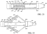
- Figs. 21-22 illustrate an exemplary use of the abrasive surface 242 on the embodiments illustrated in figs. 11-13 .
- the abrasive surface 242 is only illustrated on the proximal end of the struts 234A-B where the incising element 236 is located, though as previously discussed, the abrasive surface 242 may be located on any portion of the struts 234A-B and may be used with or without the incising element 236.
- fig. 23 illustrates an exemplary use of the abrasive surface 342 with the cantilevered embodiment illustrated in figs. 14-16 .
- the abrasive surface 342 covers substantially all of the struts 334A and 334B, though as previously discussed, the abrasive surfaces 342 may cover any portion of any number of the struts 334A and 334B and may be used with or without the incising element 336.
- abrasive surface 142, 242, and 342 are merely exemplary. It is contemplated that the abrasive surface 142, 242, and 342 may be used with any of the embodiments shown and described herein.
Abstract
Description
- This application is a continuation-in-part of Application No.
13/613,914, filed September 13, 2012 61/534,018, filed September 13, 2011 - This invention relates in general to intravascular catheters, such as can be used during minimally invasive surgical procedures. In particular, this invention relates to an intravascular catheter having an expandable incising portion.
- Atherosclerosis is a chronic condition in which atheromatous plaque accumulates on the inner walls of a blood vessel. As a result, the blood vessel walls can become inflamed and, over time, may harden to form atherosclerotic lesions that cause a narrowing of the vessel lumen. In severe cases, the atherosclerotic lesions can rupture and induce the formation of thrombus (i.e., blood clots), which can prevent blood flow through the narrowed vessel lumen.
- There are known procedures and devices for treating or otherwise reducing the risks associated with atherosclerosis. For example, an angioplasty is a procedure in which a balloon catheter is inserted into a narrowed region of the vessel lumen via a delivery catheter. The balloon catheter includes a flexible tube having an inflatable balloon at an end thereof. Once positioned in the narrowed region, the balloon is inflated in order to dilate the narrowed vessel lumen. The pressure in the balloon is generally sufficient to compress the accumulated plaque. However, in some cases it would be desirable to fragment the atherosclerotic lesions. Thus, it would be desirable to provide an intravascular catheter having an expandable portion that can be selectively controlled by a user and adapted to create incisions in atherosclerotic material to facilitate fragmentation of the material during an angioplasty procedure.
- There are known devices that perform atherectomy by abrading atherosclerotic tissue though high speed rotational movement. Such devices include the Diamondback 360® by Cardiovascular Systems, Inc.
- (http://www.csi360.com/products/coronary-diamondback-360-coronary-orbital-atherecto my-system-crowns/) and the Rotablator™ by Boston Scientific™
- (http://www.bostonscientific.com/en-US/products/plaque-modification/rotablator-rotation al-atherectomy-system.html). These devices are complex, requiring high speed motors and control systems to operate the motors. In some cases, it would be desirable to remove atherosclerotic material by micro-abrasion. Thus, it would be desirable to provide an intravascular catheter having an expandable portion and also having an abrasive surface for abrading atherosclerotic material by forward and backwards lateral movement.
- This invention relates to an intravascular catheter device for use during a surgical procedure. The catheter device includes a catheter tube having an expandable portion with a plurality of struts each defining an outer surface. The expandable portion is operable between a closed position, wherein the expandable portion has a first diameter, and an opened position, wherein the expandable portion has a second diameter that is larger than the first diameter. An incising element is provided on the outer surface of at least one of the struts. The incising element has a sharpened edge that extends outwardly in a radial direction from the outer surface of the strut for creating an incision in atherosclerotic material located within a blood vessel when the expandable portion is in the opened position.
- This invention also relates to an intravascular catheter having an expandable portion and also having abrasive surfaces. The abrasive surfaces may be located on the outer surface of the struts and may be configured to score, roughen, or remove through micro-abrasion of atherosclerotic material when the expandable portion is in the opened position and moved longitudinally within a blood vessel. The abrasive surface may be located on any portion of one or more struts and may be used with or without the incising elements.
- Various aspects of this invention will become apparent to those skilled in the art from the following detailed description of the preferred embodiments, when read in light of the accompanying drawings.
-
-
Fig. 1 is a plan view of a catheter device that includes a handle assembly and a catheter tube having an expandable incising portion, in accordance with a first embodiment of this invention. -
Fig. 2 is a cross-sectional side view of the handle assembly taken along section line 2-2 shown inFig. 1 when the catheter device is in a first operating mode. -
Fig. 3 is an enlarged cross-sectional side view of the catheter tube taken along section line 3-3 shown inFig. 1 illustrating the expandable incising portion disposed within a blood vessel. -
Fig. 4 is a cross-sectional end view of the expandable incising portion taken along section line 4-4 shown inFig. 3 . -
Fig. 5 is a cross-sectional side view of the handle assembly taken along section line 2-2 shown inFig. 1 when the catheter device is in a second operating mode. -
Fig. 6 is an enlarged cross-sectional side view of the catheter tube taken along section line 3-3 shown inFig. 1 illustrating the expandable incising portion in an opened position. -
Fig. 7 is a cross-sectional end view of the expandable incising portion taken along section line 7-7 shown inFig. 6 . -
Fig. 8 is an enlarged side view of a catheter tube having an expandable incising portion, in accordance with a second embodiment of this invention. -
Fig. 9 is a side view of the catheter tube shown inFig. 8 illustrating the expandable incising portion in an opened position. -
Fig. 10 is a cross-sectional end view of the expandable incising portion taken along section line 10-10 shown inFig. 9 . -
Fig. 11 is an enlarged side view of a catheter tube having an expandable incising portion, in accordance with a third embodiment of this invention. -
Fig. 12 is a side view of the catheter tube shown inFig. 11 illustrating the expandable incising portion in an opened position. -
Fig. 13 is an end view of the catheter tube as shown inFig. 12 . -
Fig. 14 is an enlarged side view of a catheter tube having an expandable incising portion, in accordance with a fourth embodiment of this invention. -
Fig. 15 is a side view of the catheter tube shown inFig. 14 illustrating the expandable incising portion in an opened position. -
Fig. 16 is an end view of the catheter tube as shown inFig. 15 . -
Fig. 17 is a side view of another exemplary embodiment of the device ofFig. 8 . -
Fig. 18 is a side view of the device ofFig. 17 illustrated in an opened position. -
Fig. 19 is a side view of another exemplary embodiment of the device ofFig. 8 . -
Fig. 20 is a side view of the device ofFig. 19 illustrated in an opened position. -
Fig. 21 is a side view of another exemplary embodiment of the device ofFig. 11 . -
Fig. 22 is a side view of the device ofFig. 21 illustrated in an opened position. -
Fig. 23 is a side view of another exemplary embodiment of the device ofFig. 14 . - Referring now to the drawings, there is illustrated in
Fig. 1 a catheter device, indicated generally at 10, in accordance with this invention. The illustratedcatheter device 10 is configured to treat or reduce the risks associated with atherosclerosis. In general, thecatheter device 10 includes an expandable incising portion that can be inserted into a blood vessel and expanded to create incisions in atherosclerotic material that has accumulated on inner walls of the blood vessel. The incisions facilitate the fragmentation of the atherosclerotic material during a subsequent angioplasty or atherectomy procedure. Although thecatheter device 10 will be described and illustrated in the context of treating atherosclerosis, it should be appreciated that thecatheter device 10 can be used in any desired environment and for any desired purpose. - Referring now to
Figs. 1 and2 , the illustratedcatheter device 10 includes a handle assembly, indicated generally at 20. The illustratedhandle assembly 20 includes an elongated,cylindrical handle body 21. Thehandle body 21 may alternatively have any other shape that is suitable for easy handling by a surgeon. Further, thehandle body 21 can be made from any suitably rigid material including, but not limited to, stainless steel or polymers. - As shown in
Fig. 2 , the illustratedhandle body 21 defines aninternal chamber 22. Apassage 23 extends into an end portion of thehandle body 21 for communication with theinternal chamber 22. Thehandle body 21 further includes aslot 24 that extends through a side wall thereof for communication with theinternal chamber 22. The illustratedslot 24 may have any length or width as desired. As shown inFig. 1 , anindicator 24A may be provided on thehandle body 21 adjacent to theslot 24. For example, theindicator 24A can be a visual scale or any other indicating means, the purpose of which will be explained below. - The illustrated
handle assembly 20 also includes acontrol member 25 that is supported on thehandle body 21 for sliding movement within theslot 24. For example, thecontrol member 25 is movable between a forward position (shown inFig. 2 ), a rearward position (shown inFig. 5 ), or any position therebetween, which will be further explained below. As shown inFig. 2 , the illustratedcontrol member 25 includes abase portion 26 that is disposed within theinternal chamber 22 of thehandle body 21. Thebase portion 26 may define an outer cross-sectional shape that generally corresponds with a cross-sectional shape of theinternal chamber 22, although such is not required. Alternatively, (or in addition), thecontrol member 25 may be movably supported on thehandle body 21 by a bearing, a bushing, a guide rail, or any other structural means. In other embodiments, thecontrol member 25 may be supported for rotational movement, pivotal movement, or any other type of movement relative to thehandle body 21, the purpose of which will become apparent below. Thevisual indicator 24A, described above, is configured to identify the relative position of thecontrol member 25 with respect to thehandle body 21. - The illustrated
handle assembly 20 also includes alocking mechanism 27 that is configured to temporarily secure thecontrol member 25 in a desired position, although such is not required. As shown inFig. 2 , the illustratedlocking mechanism 27 includes a plurality of protrusions that are spaced apart from one another along an inner surface of theslot 24. Thecontrol member 25 frictionally engages the protrusions to hold thecontrol member 25 in the desired position. Alternatively, thelocking mechanism 27 may be a threaded fastener, a pivotal latch, a push-button release, or any other mechanism that is configured to secure thecontrol member 25 in a desired position. - Referring now to
Figs. 1 through 3 , the illustratedcatheter device 10 also includes acatheter tube 30 that extends from thehandle assembly 20. Thecatheter tube 30 is an elongated, flexible member having a proximal end that is secured to thehandle assembly 20 and a distal end that extends therefrom. Thecatheter tube 30 can be made from any biocompatible material including, but not limited to, polyvinyl, polyethylene, nitinol, or stainless steel. Further, thecatheter tube 30 can have any outer diameter, length, or wall thickness. - As shown in
Fig. 2 , the proximal end of thecatheter tube 30 is secured to thehandle body 21 and communicates with theinternal cavity 22 through thepassage 23. Thecatheter tube 30 may be secured to thehandle body 21 using a flanged connection, a fused connection, an adhesive, a press-fit connection, a threaded connection, or any other securing means. Alternatively, thecatheter tube 30 may be secured to thehandle body 21 using a connector or any other type of attachment device. - As shown in
Figs. 1 and3 , anexpandable portion 32 is provided on the distal end of thecatheter tube 30. The illustratedexpandable portion 32 is a cylindrical member having a longitudinal axis. Theexpandable portion 32 can be made from a generally resilient material that is able to flex between various positions, such as polyvinyl, polyethylene, nitinol, or stainless steel. Theexpandable portion 32 can be secured to thecatheter tube 30 in any manner including, but not limited to, a fused connection, an adhesive, a press-fit connection, a threaded connection, or any other securing means. Alternatively, theexpandable portion 32 can be integrally formed from thecatheter tube 30. Further, theexpandable portion 32 can have any outer diameter, length, or wall thickness. - The illustrated
expandable portion 32 has a pair ofstruts slits 35A and 35B that extend through side walls of theexpandable portion 32. As shown inFig. 4 , theslits 35A and 35B are equally spaced apart from one another around the circumference of theexpandable portion 32 such that thestruts struts - As shown in
Figs. 3 and 4 , the illustratedexpandable portion 32 also includes a pair of incisingelements 36 that are respectively provided along outer surfaces of thestruts elements 36 can be atherotomes or other incising members having arcuate shaped sharpened edges, for example, that are configured to create incisions in atherosclerotic material as will be explained below. The illustratedincising elements 36 extend parallel with the longitudinal axis of theexpandable portion 32 and outwardly in a radial direction therefrom. The incisingelements 36 are equally spaced apart from one another around the circumference of theexpandable portion 32. Theexpandable portion 32 may, however, have any number or configuration of incisingelements 36 provided around the circumference thereof. Further, the incisingelements 36 can have any cross-sectional shape, longitudinal length, or height and can be made from any suitable material including, but not limited to, tempered steel, stainless steel, high carbon steel, or ceramics. The incisingelements 36 can be molded with thestruts - The distal end of the
expandable portion 32 may optionally include atip member 38. The illustratedtip member 38 has a generally conical shape that facilitates insertion of thecatheter tube 30 within a blood vessel 50 (seeFigs. 3 and 4 ) and subsequent travel therethrough. Thetip member 38 may, however, have any desired shape. An aperture may axially extend through thetip member 38, the purpose of which will be explained below. Thetip member 38 can be integrally formed with theexpandable portion 32 or may be secured thereto, such as with an adhesive or the like. Further, thetip member 38 can be made from any biocompatible material including, but not limited to, polyvinyl, polyethylene, nitinol, stainless steel, or polyether block amide. - As shown in
Figs. 2 through 4 , the illustratedcatheter device 10 also includes aninner sleeve 40, although such is not required. Theinner sleeve 40 is a flexible, tubular member that is supported for sliding movement within thecatheter tube 30, the purpose of which will be explained below. Theinner sleeve 40 can be made from any biocompatible material including, but not limited to, polyvinyl, polyethylene, nitinol, stainless steel, or a woven material. Further, theinner sleeve 40 can have any outer diameter, length, or wall thickness. Theinner sleeve 40 need not be a tubular member but may alternatively be a solid wire, a braided wire, or the like. - As shown in
Fig. 2 , a proximal end of theinner sleeve 40 extends from thecatheter tube 30 and into theinternal chamber 22 of thehandle body 21. The proximal end of theinner sleeve 40 is secured to thebase portion 26 of thecontrol member 25 for sliding movement therewith, the purpose of which will be explained below. Theinner sleeve 40 can be secured to thebase portion 26 by a flanged connection, a fused connection, an adhesive, a threaded connection, or any other securing means. - As shown in
Fig. 3 , theinner sleeve 40 extends through an entire length of thecatheter tube 30. A distal end of theinner sleeve 40 that is opposite thehandle assembly 20 is secured to thetip member 38, which is in turn secured to theexpandable portion 32. Theinner sleeve 40 may be secured to thetip member 38 in any manner including, but not limited to, a fused connection, an adhesive, a fastener, or the like. - Referring back to
Figs. 1 and2 , the illustratedcatheter device 10 also includes aprotective sheath 42 that is supported for sliding movement along an outer surface of thecatheter tube 30, although such is not required. Theprotective sheath 42 can be made from any biocompatible material including, but not limited to, polyvinyl, polyethylene, nitinol, or stainless steel. Further, theprotective sheath 42 can have any outer diameter, length, or wall thickness. The purpose of theprotective sheath 42 will be explained below. - The illustrated
protective sheath 42 includes a flange 44 that facilitates sliding movement of theprotective sheath 42 relative to thecatheter tube 30. The illustrated flange 44 is an annular member that is located at an end of theprotective sheath 42 nearest thehandle assembly 20. The flange 44 can be integrally formed with theprotective sheath 42 or may otherwise be secured thereto in any manner, such as with an adhesive or the like. It should be appreciated that the flange 44 can have any shape or may alternatively be configured in any manner to accomplish the functions described herein and below. - The operation of the
catheter device 10 will now be described with reference toFigs. 1 through 7 . Referring initially toFigs. 1 through 4 , thecatheter device 10 is illustrated in a first operating mode. In the first operating mode, thecontrol member 25 on thehandle assembly 20 is located in the forward position relative to thehandle body 21. Theinner sleeve 40 fully extends into thecatheter tube 30 such that theexpandable portion 32 is in a closed position, as shown inFigs. 3 and 4 . In the closed position, thestruts inner sleeve 40. Theslits 35A and 35B (illustrated by the dashed lines inFig. 3 ) remain in a generally closed configuration. As such, theexpandable portion 32 defines an initial diameter D1, which is generally the same diameter as the remaining length of thecatheter tube 30. The initial diameter D1 of theexpandable portion 32 may, however, be any desired dimension. - When the
catheter device 10 is in the first operating mode, the distal end of thecatheter tube 30 can be percutaneously inserted into ablood vessel 50, as shown inFigs. 3 and 4 . The illustratedcatheter tube 30 is then advanced through theblood vessel 50 along aguide wire 52, which extends through thecatheter device 10. For example, theguide wire 52 may fully extend through theinner sleeve 40, into theinternal chamber 22 of thehandle body 21, and exit a rear end of the handle assembly 20 (seeFig. 2 ). Thecatheter tube 30 is advanced along theguide wire 52 until theexpandable portion 32 is positioned in a narrowed region of theblood vessel 50 caused byatherosclerotic material 54. Alternatively, thecatheter tube 30 can be inserted into theblood vessel 50 and guided therethrough by a delivery catheter (not shown) or any other suitable procedure. During insertion and advancement of thecatheter tube 30 through theblood vessel 50, the optionalprotective sheath 42 is preferably positioned over theexpandable portion 32, thereby preventing the incisingelements 36 from coming into contact with inner walls of theblood vessel 50. - Once the
expandable portion 32 is positioned in the narrowed region of theblood vessel 50, the incisingelements 36 can be exposed by sliding theprotective sheath 42 back from the distal end of thecatheter tube 30, as indicated by the direction arrows inFig. 3 . The illustratedprotective sheath 42 can be moved in this manner by pulling the flange 44 towards thehandle assembly 20, which is indicated by the direction arrows inFig. 2 . - Referring now to
Figs. 5 through 7 , thecatheter device 10 is illustrated in a second operating mode. To achieve the second operating mode, thecontrol member 25 is moved from the forward position to the rearward position, as indicated by the direction arrow inFig. 5 . As thecontrol member 25 is moved to the rearward position, theinner sleeve 40 is drawn within thecatheter tube 30 thereby reducing the relative length of theinner sleeve 40 with respect to thecatheter tube 30. The distal end of theinner sleeve 40 is attached to thetip member 38, as described above, causing theexpandable portion 32 to become axially compressed between thetip member 38 and the distal end of thecatheter tube 30. As a result, thestruts expandable portion 32 defines a second diameter D2 that is larger than the initial diameter D1 when theexpandable portion 32 is in the closed position. As shown inFig. 6 , the incisingelements 36 are respectively positioned along the radially outer most surfaces of thestruts struts struts expandable portion 32 can achieve a desired overall second diameter D2 in the opened position. - During operation of the
catheter device 10, the second diameter D2 can be increased or decreased by selective movement of thecontrol member 25 between the forward and rearward positions. For example, a larger second diameter D2 can be achieved by moving thecontrol member 25 further towards the rearward position. Conversely, a smaller second diameter D2 can be achieved by moving thecontrol member 25 further towards the forward position. Thevisual indicator 24A can be used to identify the instantaneous second diameter D2 of theexpandable portion 32. Alternatively (or in addition), thestruts protective sheath 42 is slid back from theexpandable portion 32. As such, sliding movement of theprotective sheath 42 relative to thestruts inner sleeve 40 and the movable components of thehandle assembly 20 may not be necessary. - When the
catheter device 10 is in the second operating mode, theexpandable portion 32 can be pulled along theguide wire 52 through the narrowed region of theblood vessel 50. This can be accomplished by pulling on thehandle assembly 20. In doing so, the incisingelements 36 engage theatherosclerotic material 54 and createlongitudinal incisions 56 therein. As shown inFigs. 6 and 7 , the outer surface area of the arcuate shapedstruts element 36, is configured to ride along a surface of theatherosclerotic material 54, thereby limiting the depth of theincisions 56 and preventing the incisingmembers 36 from cutting the walls of theblood vessel 50. Theexpandable portion 32 can be moved any distance along theguide wire 52 to createincisions 56 having any desired length. After theincisions 56 are made in theatherosclerotic material 54, thecatheter device 10 can be returned to the first operating mode (shown inFigs. 1 through 4 ) by moving thecontrol member 25 to the forward position. In doing so, theexpandable portion 32 returns to the closed position. Theprotective sheath 42 can be slid over theexpandable portion 32 and thecatheter tube 30 may be removed from theblood vessel 50. - Alternatively, the
catheter device 10 can be used to createadditional incisions 56 in theatherosclerotic material 54. For example, after thecatheter device 10 has been returned to the first operating mode, theexpandable portion 32 can be relocated within the narrowed region of theblood vessel 50. Thecatheter tube 30 can then be rotated within theblood vessel 50 by rotating thehandle assembly 20 so as to align the incisingelements 36 with other portions of theatherosclerotic material 54. The previous steps can then be repeated any number of times to make multiple passes through the narrowed region of theblood vessel 50 and create additional incisions in theatherosclerotic material 54. - Thus, it should be appreciated that the illustrated
catheter device 10 is advantageous in many respects. In one example, the second diameter D2 of theexpandable portion 32 can be selectively controlled by operation of thehandle assembly 20 or by sliding movement of theprotective sheath 42. This enables thecatheter device 10 to be adapted for use inblood vessels 50 of different sizes or varying diameters. In another example, the illustratedcatheter device 10 can apply varying magnitudes of radial forces to theatherosclerotic material 54 by controlling the amount of force being applied to thecontrol member 25 on thehandle assembly 20. This enables thecatheter device 10 to generate sufficient radial force to createincisions 56 inatherosclerotic material 54 while reducing the potential for tearing the walls of theblood vessel 50. In yet another example, thecatheter device 10 can be used to make any number of passes during a single procedure to makemultiple incisions 56 inatherosclerotic material 54 of varying lengths and shapes. - Referring now to
Figs. 8 through 10 , there is illustrated acatheter tube 130 having anexpandable portion 132, in accordance with a second embodiment of this invention. Thecatheter tube 130 and theexpandable portion 132 may include any structural features as described and illustrated above in the previous embodiment, although such is not required. Similar features have been numbered with common reference numerals but have been increased by 100 (i.e., 110, 120, 130, etc.). It should be appreciated that similar features are structured similarly, operate similarly, and/or have the same function unless otherwise indicated by the drawings or this specification. - For example, the
catheter tube 130 may extend from a handle assembly (not shown) as described above in the first embodiment. Theexpandable portion 132 is provided on a distal end of thecatheter tube 130 and may include atip member 138. Thecatheter tube 130 may also include aninner sleeve 140 and a protective sheath (not shown), which is also described above in the first embodiment. - In the illustrated embodiment, however, the
expandable portion 132 includes fourstruts slits element 136, although such is not required. It should be appreciated that theexpandable portion 132 may have any number or configuration of struts and incising elements as desired. - As shown in
Fig. 8 , the illustratedexpandable portion 132 further includes recessedportions 160 that respectively extend into the outer surfaces of thestruts struts inner sleeve 140 when in the closed position or, alternatively, may have a reduced thickness along a central portion thereof to create the recessedportions 160. The illustrated incisingelements 136 are respectively disposed within the recessedportions 160. Thus, when thecatheter tube 130 is inserted into a blood vessel, as described above, the recessedportions 160 help to prevent the incisingelements 136 from coming into contact with inner walls of the blood vessel. On the other hand, when theexpandable portion 132 is expanded to an opened position, as explained below, the incisingelements 136 become exposed from the recessedportions 160. It should be appreciated that the recessedportions 160 can eliminate or reduce the need for the protective sheath (not shown). Theguide wire 152 may extend through the entire device. - The
expandable portion 132 can be operated between a closed position (shown inFig. 8 ) and an opened position (shown inFigs. 9 and 10 ) by selective movement of theinner sleeve 140 relative to thecatheter tube 130, as described above in the first embodiment. Alternatively (or in addition), thestruts expandable portion 132 between the closed position and the opened position. - Referring now to
Figs. 11 through 13 , there is illustrated acatheter tube 230 having anexpandable portion 232, in accordance with a third embodiment of this invention. Thecatheter tube 230 and theexpandable portion 232 may include any structural features as described and illustrated above in the previous embodiments, although such is not required. Similar features have been numbered with common reference numerals but have been increased by 200 (i.e., 210, 220, 230, etc.). It should be appreciated that similar features are structured similarly, operate similarly, and/or have the same function unless otherwise indicated by the drawings or this specification. - For example, the
catheter tube 230 may extend from a handle assembly (not shown) as described above in the first embodiment. Theexpandable portion 232 is provided on a distal end of thecatheter tube 230 and includes a pair ofstruts slits catheter tube 230 may also include atip member 238, aninner sleeve 240, and a protective sheath (not shown), which is described above in the first embodiment. Theguide wire 252 may extend through the entire device. - In the illustrated embodiment, however, the
expandable portion 232 includes a first pair of weakenedregions regions struts regions expandable portion 232 that function as hinges. The weakenedregions expandable portion 232 when thestruts struts regions - The illustrated struts 234A and 234B remain generally flat along respective lengths thereof in both a closed position (shown in
Fig. 11 ) and an opened position (shown inFigs. 12 and 13 ) so as to form an apex, although such a configuration is not required. The incisingelements 236 are provided along the generally flat portion of therespective struts elements 236 may also function as stiffening members for increasing the strength of thestruts elements 236 and thestruts struts - As shown in
Fig. 12 , end portions of the incisingelements 236 may extend beyond the apex that is formed by each of therespective struts elements 236 when theexpandable portion 232 is in the opened position. As such, the incisingelements 236 may have a reduced height when theexpandable portion 232 is in the closed position, which may eliminate the need for the protective sheath (not shown). - The
expandable portion 232 can be operated between the closed position and the opened position by selective movement of theinner sleeve 240 relative to thecatheter tube 230, as described above in the first embodiment. Alternatively (or in addition), thestruts expandable portion 232 between the closed position and the opened position. - Referring now to
Figs. 14 through 16 , there is illustrated acatheter tube 330 having anexpandable portion 332, in accordance with a fourth embodiment of this invention. Thecatheter tube 330 and theexpandable portion 332 may include any structural features as described and illustrated above in the previous embodiments, although such is not required. Similar features have been numbered with common reference numerals but have been increased by 300 (i.e., 310, 320, 330, etc.). It should be appreciated that similar features are structured similarly, operate similarly, and/or have the same function unless otherwise indicated by the drawings or this specification. - For example, the
catheter tube 330 may extend from a handle assembly (not shown) as described above in the first embodiment. Theexpandable portion 332 is provided on a distal end of thecatheter tube 330 and may include atip member 338. Thecatheter tube 330 may also include aninner sleeve 340 that is attached to thetip member 338 and a protective sheath (not shown), which is also described above in the first embodiment. Theguide wire 352 may extend through the entire device. - In the illustrated embodiment, however, the
expandable portion 332 includes a pair ofstruts tip member 338 at their distal ends), the purpose of which will be explained below. Thestruts slits 335A and 335B that extend from the end of theexpandable portion 332. A pair of incisingelements 336 is respectively provided along outer surfaces of thestruts expandable portion 332 may have any number or configuration of struts and incising elements as desired. - As shown in
Figs. 15 and 16 , the illustrated struts 334A and 334B are supported on theexpandable portion 332 so that they can be splayed open in a Y-shaped configuration. For example, thestruts inner sleeve 340 within thecatheter tube 330, as described above in the first embodiment. In doing so, thetip member 338 slides along the inner surfaces of thestruts struts expandable portion 332 between a closed position and the splayed open position. - The
struts Fig. 14 ) and the splayed open position, although such is not required. As such, the incisingelements 336 may also function as stiffening members for increasing the strength of thestruts elements 336 and thestruts struts - As shown in
Fig. 15 , end portions of the incisingelements 336 may extend beyond the distal ends of therespective struts elements 336 when theexpandable portion 332 is in the splayed open position. As such, the incisingelements 336 may have a reduced height when theexpandable portion 332 is in the closed position, which may eliminate the need for the protective sheath (not shown). -
Figs. 17-28 illustrate various exemplary embodiments of the present invention comprising anabrasive surface 142.Figs. 17-18 for example, illustrate the device offigs. 8-9 , respectively, but additionally comprising theabrasive surface 142. Theabrasive surface 142 may be any abrasive substance added to the surface of thestruts 134A-C. In other exemplary embodiments, theabrasive surface 142 may be a coating or a surface treatment (for example, roughening) performed on the surface of thestruts 134A-C. For example, but not to serve as a limitation, diamond dust may be added to the surface of thestruts 134A-C or the surface of thestruts 134A-C may be roughened to produce burrs. - Regardless, the
abrasive surface 142 may be of any grit size, though exemplary embodiments may be a 30-70 micron grit, inclusive. Theabrasive surface 142 may extend over the entire length or over any portion of thestruts 134A-C. For example, but not to serve as a limitation, theabrasive surface 142 may be limited to the area around the incisingelement 136, the proximal half of thestruts 134A-C, or the distal half of thestruts 134A-C. Likewise, theabrasive surface 142 may be located on any number of thestruts 134A-C. - The
abrasive surface 142 may be configured to contact and score, roughen, move, micro-abrade and/or otherwise abradeatherosclerotic material 54 located in theblood vessel 50 when theexpandable portion 132 is placed in the opened position and moved axially forwards and/or backwards through theblood vessel 50. Any type of abrasion where a substance is broken into smaller particulate is contemplated. In exemplary embodiments of the present invention, theatherosclerotic material 54 is abraded into very fine particulate, preferably on the micron order of magnitude though any type of abrasion into any size particulate is contemplated. Although reference is made to abradingatherosclerotic material 54, it is contemplated that the present invention may additionally be configured and/or used to abrade other structures or blockages located within or that form a part of the vascular system. More specifically, the incisingelement 136 may enter theatherosclerotic material 54, thus fragmenting it, while thestruts 134A-C and theabrasive surface 142 thereon may ride across the surface of theatherosclerotic material 54, thus abrading it. In other exemplary embodiments of the present invention where the incisingelements 136 are not used, theabrasive surface 142 may simply abrade the surface of theatherosclerotic material 54 by lateral movement of theexpandable portion 132. - The
abrasive surface 142 may abrade theatherosclerotic material 54 into sufficiently small pieces that it can be reabsorbed by the body, such as but not limited to through theblood vessel 50 wall, or travel safely through the vascular system. In other exemplary embodiments, theabrasive surface 142 may abrade theatherosclerotic material 54 to facilitate and enhance the effectiveness of further treatment, such as but not limited, angioplasty. For example, but not to serve as a limitation, theabrasive surface 142 may break the surface tension on theatherosclerotic material 54, thus making subsequent angioplasty more effective. -
Figs. 19-20 illustrate that theabrasive surface 142 may be used without the incisingelement 136. -
Figs. 21-22 illustrate an exemplary use of theabrasive surface 242 on the embodiments illustrated infigs. 11-13 . In these figures theabrasive surface 242 is only illustrated on the proximal end of thestruts 234A-B where the incisingelement 236 is located, though as previously discussed, theabrasive surface 242 may be located on any portion of thestruts 234A-B and may be used with or without the incisingelement 236. - Similarly,
fig. 23 illustrates an exemplary use of theabrasive surface 342 with the cantilevered embodiment illustrated infigs. 14-16 . In this figure theabrasive surface 342 covers substantially all of thestruts abrasive surfaces 342 may cover any portion of any number of thestruts element 336. - The embodiments in
figs. 17-23 incorporating theabrasive surface abrasive surface - Additional statements of invention are set out below.
- Statement 1. An intravascular catheter device for the treatment of atherosclerotic material located within a blood vessel comprising:
- a flexible catheter tube;
- an expandable portion secured to a distal end of said catheter tube and comprising a plurality of struts each defining an outward facing surface, the expandable portion being operable between a closed position, wherein the expandable portion has a first diameter, and an opened position, wherein the expandable portion has a second diameter that is larger than the first diameter;
- an inner sleeve disposed within the catheter tube wherein said inner sleeve is supported for sliding movement within the catheter tube, is configured to accommodate a guide wire extending through substantially the centerline thereof, and is configured to move the expandable portion between the opened and the closed positions;
- an incising member provided on and extending from the outward facing surface of at least one of the struts, the incising member having a sharpened edge located along an upper edge thereof wherein said sharpened edge extends substantially in parallel with a longitudinal axis of the expandable portion when the expandable portion is in the closed position; and
- an abrasive surface located on at least one of the struts configured to abrade atherosclerotic material by laterally moving the expandable portion through the blood vessel while the expandable portion is in the opened position.
- Statement 2. The intravascular catheter device of statement 1 wherein:
- the abrasive surface is located on substantially the distal half of the struts.
- Statement 3. The intravascular catheter device of statement 1 wherein:
- the abrasive surface is located on substantially the proximal half of the struts.
- Statement 4. The intravascular catheter device of statement 1 wherein:
- the abrasive surface is located along substantially the entirety of the struts.
- Statement 5. The intravascular catheter device of statement 1 wherein:
- the abrasive surface is located on the portions of the struts in close proximity to the incising element.
- Statement 6. The intravascular catheter device of statement 1 further comprising:
- a tip member attached to the inner sleeve and the expandable portion so as to move the struts between the closed position and the opened position when the tip member is extended or retracted relative to the catheter tube.
- Statement 7. The intravascular catheter device of statement 1 wherein:
- the abrasive surface comprises a diamond dust.
- Statement 8. The intravascular catheter device of statement 1 wherein:
- the abrasive surface has a grit size between 30 and 70 microns, inclusive.
- Statement 9. The intravascular catheter device of statement 1 wherein:
- said abrasive surface is configured to abrade the atherosclerotic material into sufficiently small pieces such that they are capable of being absorbed by the body or travel safely through the vascular system.
-
Statement 10. The intravascular catheter device of statement 1 wherein:- the struts are supported in a cantilevered fashion on the expandable portion so as to be splayed open when in the opened position.
- Statement 11. The intravascular catheter device of statement 1 further comprising:
- a protective sheath supported for sliding movement along an outer surface of the catheter tube to control movement of the expandable portion between the closed and the opened position.
- Statement 12. The intravascular catheter device of statement 11 wherein:
- the struts are biased in the opened position.
- Statement 13. An intravascular catheter device for the treatment of atherosclerotic material located within a blood vessel comprising:
- a flexible catheter tube;
- an expandable portion secured to a distal end of said catheter tube comprising a trio of struts each defining an outer facing surface and being operable between a collapsed position, wherein the expandable portion has a first diameter, and an expanded position, wherein the expandable portion has a second diameter that is larger than the first diameter;
- a flexible inner sleeve disposed within the catheter tube wherein said inner sleeve is supported for sliding movement within the catheter tube and is configured to accommodate a guide wire extending through substantially the centerline thereof;
- a tip member attached to the inner sleeve and the expandable portion so as to move the struts between the closed position and the opened position when the tip member is extended or retracted relative to the catheter tube;
- a handle assembly secured to a proximal end of said catheter tube and comprising a locking mechanism for selectively securing the position of the tip member; and
- an abrasive surface located on each of said trio of struts and configured to abrade atherosclerotic material when the expandable portion is in the opened position and moved laterally through the blood vessel;
- wherein said abrasive surface is configured to abrade the atherosclerotic material into sufficiently small pieces such that they are capable of being absorbed by the body or travel safely through the vascular system.
- Statement 14. The intravascular catheter device of statement 13 wherein:
- the abrasive surface is located on substantially the distal half of the struts.
- Statement 15. The intravascular catheter device of statement 13 wherein:
- the abrasive surface is located on substantially the proximal half of the struts.
- Statement 16. The intravascular catheter device of statement 13 wherein:
- the abrasive surface is located along substantially the entire length of the strut.
- Statement 17. The intravascular catheter device of statement 13 further comprising:
- a protective sheath supported for sliding movement along an outer surface of the catheter tube to control movement of the expandable portion between the closed and the opened position.
- Statement 18. An intravascular catheter device for the treatment of atherosclerotic material located within a blood vessel comprising:
- a flexible catheter tube;
- an expandable portion secured to a distal end of said catheter tube comprising a plurality of members each defining an outer facing surface and being operable between a collapsed position, wherein the expandable portion has a first diameter, and an expanded position, wherein the expandable portion has a second diameter that is larger than the first diameter;
- an incising element provided on and extending longitudinally along a proximal portion of and substantially perpendicular from, the outer facing surface of at least one of the members, said incising element comprising a sharpened edge; and
- an abrasive surface located on each of the struts in the area of the struts in close proximity with the incising element, wherein said abrasive surface is configured to abrade atherosclerotic material when the expandable portion is in the opened position and moved laterally through the blood vessel.
- Statement 19. The intravascular catheter device of statement 18 wherein:
- the incising element extends along substantially the midline of the member; and
- the sharpened edge extends substantially in parallel with a longitudinal axis of the expandable portion when the expandable portion is in the closed position.
-
Statement 20. The intravascular catheter device of statement 18 wherein:- said abrasive surface is configured to abrade the atherosclerotic material into sufficiently small pieces such that the pieces are capable of being absorbed by the body or travel safely through the vascular system.
- The principle and mode of operation of this invention have been explained and illustrated in its preferred embodiments. However, it must be understood that this invention may be practiced otherwise than as specifically explained and illustrated without departing from its spirit or scope.
Claims (15)
- An intravascular catheter device (10) for the treatment of atherosclerotic material (54) located within a blood vessel (50) comprising:a flexible catheter tube (30, 130, 230, 330);a handle assembly (20) secured to a proximal end of said catheter tube (30, 130, 230, 330) and comprising a control member (25) that is moveably supported thereon;an expandable portion (32, 132, 232, 332) secured to a distal end of said catheter tube (30, 130, 230, 330) and comprising a plurality of struts (34A, 34B, 134A, 134B, 134C, 134D, 234A, 234B, 334A, 334B) each defining an outward facing surface, the expandable portion (32, 132, 232, 332) being operable between a closed position, wherein the expandable portion (32, 132, 232, 332) has a first diameter, and an opened position, wherein the expandable portion (32, 132, 232, 332) has a second diameter that is larger than the first diameter;an inner sleeve (40, 140, 240, 340) disposed within the catheter tube (30, 130, 230, 330) wherein said inner sleeve (40, 140, 240, 340) is supported for sliding movement within the catheter tube (30, 130, 230, 330), is configured to accommodate a guide wire (52, 152, 252, 352) extending through substantially the centerline thereof, and is connected between the control member (25) and a distal end of the expandable portion (32, 132, 232, 332) such that the inner sleeve (30, 130, 230, 330) is configured to move the expandable portion (32, 132, 232, 332) between the opened and the closed positions;an abrasive surface (142, 242, 342) located on at least one of the struts (34A, 34B, 134A, 134B, 134C, 134D, 234A, 234B, 334A, 334B) configured to abrade atherosclerotic material (54) by laterally moving the expandable portion (32, 132, 232, 332) through the blood vessel (50) while the expandable portion (32, 132, 232, 332) is in the opened position.
- The intravascular catheter device (10) of any of the preceding claims wherein:the abrasive surface (142, 242, 342) is located on substantially the distal half of the struts (34A, 34B, 134A, 134B, 134C, 134D, 234A, 234B, 334A, 334B).
- The intravascular catheter device (10) of any of the preceding claims wherein:the abrasive surface (142, 242, 342) is located on substantially the proximal half of the struts (34A, 34B, 134A, 134B, 134C, 134D, 234A, 234B, 334A, 334B).
- The intravascular catheter device (10) of any of the preceding claims wherein:the abrasive surface (142, 242, 342) is located along substantially the entirety of the struts (34A, 34B, 134A, 134B, 134C, 134D, 234A, 234B, 334A, 334B).
- The intravascular catheter device (10) of any of the preceding claims further comprising:an incising element (36, 136, 236, 336) provided on and extending from the outward facing surface of at least one of the struts (34A, 34B, 134A, 134B, 134C, 134D, 234A, 234B, 334A, 334B), the incising element (36, 136, 236, 336) having a sharpened edge located along an upper edge thereof wherein said sharpened edge extends substantially in parallel with a longitudinal axis of the expandable portion (32, 132, 232, 332) when the expandable portion (32, 132, 232, 332) is in the closed position.
- The intravascular catheter device (10) of claim 6 wherein:the abrasive surface (142, 242, 342) is located only on the portions of the struts (34A, 34B, 134A, 134B, 134C, 134D, 234A, 234B, 334A, 334B) in close proximity to the incising element (36, 136, 236, 336).
- The intravascular catheter device of any of the preceding claims further comprising:a tip member (36, 136, 236, 336) forming the distal end of the expandable portion (32, 132, 232, 332) and attached to the inner sleeve (40, 140, 240, 340) and the struts (34A, 34B, 134A, 134B, 134C, 134D, 234A, 234B, 334A, 334B) so as to move the struts (34A, 34B, 134A, 134B, 134C, 134D, 234A, 234B, 334A, 334B) between the closed position and the opened position when the tip member (36, 136, 236, 336) is extended or retracted relative to the catheter tube (30, 130, 230, 330).
- The intravascular catheter device of any of the preceding claims wherein:the abrasive surface (142, 242, 342) comprises a diamond dust.
- The intravascular catheter device of any of the preceding claims wherein:the abrasive surface (142, 242, 342) has a grit size between 30 and 70 microns, inclusive.
- The intravascular catheter device of any of the preceding claims wherein:said abrasive surface (142, 242, 342) is configured to abrade the atherosclerotic material (54) into sufficiently small pieces such that they are capable of being absorbed by the body or travel safely through the vascular system.
- The intravascular catheter device of any of the preceding claims wherein:the struts (34A, 34B, 134A, 134B, 134C, 134D, 234A, 234B, 334A, 334B) are supported in a cantilevered fashion on the expandable portion (32, 132, 232, 332) so as to be splayed open when in the opened position.
- The intravascular catheter device of any of the preceding claims further comprising:a protective sheath (32, 132, 232, 332) supported for sliding movement along an outer surface of the catheter tube (30, 130, 230, 330) to control movement of the expandable portion (32, 132, 232, 332) between the closed and the opened position.
- The intravascular catheter device of any of the preceding claims wherein:the struts (34A, 34B, 134A, 134B, 134C, 134D, 234A, 234B, 334A, 334B) are biased in the opened position.
- The intravascular catheter device (10) of claims 5 or 6 wherein:the incising element (36, 136, 236, 336) extends along substantially the midline of the strut (34A, 34B, 134A, 134B, 134C, 134D, 234A, 234B, 334A, 334B); andthe sharpened edge extends substantially in parallel with a longitudinal axis of the expandable portion (32, 132, 232, 332) when the expandable portion (32, 132, 232, 332) is in the closed position.
- The intravascular catheter device (10) of any of claims 1-10 or 12-14 wherein:the struts (34A, 34B, 134A, 134B, 134C, 134D, 234A, 234B, 334A, 334B) are respectively attached to one another at their opposite ends and bow outwardly in the opened position.
Applications Claiming Priority (1)
| Application Number | Priority Date | Filing Date | Title |
|---|---|---|---|
| US15/441,398 US11357533B2 (en) | 2011-09-13 | 2017-02-24 | Intravascular catheter having an expandable incising portion and abrasive surfaces |
Publications (2)
| Publication Number | Publication Date |
|---|---|
| EP3366239A1 true EP3366239A1 (en) | 2018-08-29 |
| EP3366239B1 EP3366239B1 (en) | 2020-08-12 |
Family
ID=61256859
Family Applications (1)
| Application Number | Title | Priority Date | Filing Date |
|---|---|---|---|
| EP18158211.5A Active EP3366239B1 (en) | 2017-02-24 | 2018-02-22 | Intravascular catheter having an expandable incising portion and abrasive surfaces |
Country Status (3)
| Country | Link |
|---|---|
| US (1) | US20220240974A1 (en) |
| EP (1) | EP3366239B1 (en) |
| ES (1) | ES2831026T3 (en) |
Cited By (5)
| Publication number | Priority date | Publication date | Assignee | Title |
|---|---|---|---|---|
| CN111759364A (en) * | 2020-06-17 | 2020-10-13 | 复旦大学附属华山医院 | Blood vessel chronic occlusion lesion positioning system |
| CN113331919A (en) * | 2021-07-13 | 2021-09-03 | 江苏迈得诺医疗集团有限公司 | Device and system for removing blood vessel caking |
| US11690645B2 (en) | 2017-05-03 | 2023-07-04 | Medtronic Vascular, Inc. | Tissue-removing catheter |
| US11819236B2 (en) | 2019-05-17 | 2023-11-21 | Medtronic Vascular, Inc. | Tissue-removing catheter |
| US11871958B2 (en) | 2017-05-03 | 2024-01-16 | Medtronic Vascular, Inc. | Tissue-removing catheter with guidewire isolation liner |
Citations (4)
| Publication number | Priority date | Publication date | Assignee | Title |
|---|---|---|---|---|
| WO1999018862A1 (en) * | 1997-10-10 | 1999-04-22 | Hearten Medical, Inc. | A catheter device for abrading a patent foramen ovale and method of using the device |
| US20140364896A1 (en) * | 2013-06-07 | 2014-12-11 | Abott Cardiovascular Systems, Inc. | Device, system, and method for thrombus retrieval |
| US20150133978A1 (en) * | 2013-11-11 | 2015-05-14 | Cook Medical Technologies Llc | Devices and methods for modifying veins and other bodily vessels |
| WO2015195606A1 (en) * | 2014-06-16 | 2015-12-23 | Pigott John P | Intravascular catheter having an expandable incising portion and drug delivery mechanism |
Family Cites Families (1)
| Publication number | Priority date | Publication date | Assignee | Title |
|---|---|---|---|---|
| US20090306690A1 (en) * | 2008-06-05 | 2009-12-10 | Cardiovascular Systems, Inc. | Abrasive nose cone with expandable cutting and sanding region for rotational atherectomy device |
-
2018
- 2018-02-22 EP EP18158211.5A patent/EP3366239B1/en active Active
- 2018-02-22 ES ES18158211T patent/ES2831026T3/en active Active
-
2022
- 2022-04-25 US US17/728,214 patent/US20220240974A1/en active Pending
Patent Citations (4)
| Publication number | Priority date | Publication date | Assignee | Title |
|---|---|---|---|---|
| WO1999018862A1 (en) * | 1997-10-10 | 1999-04-22 | Hearten Medical, Inc. | A catheter device for abrading a patent foramen ovale and method of using the device |
| US20140364896A1 (en) * | 2013-06-07 | 2014-12-11 | Abott Cardiovascular Systems, Inc. | Device, system, and method for thrombus retrieval |
| US20150133978A1 (en) * | 2013-11-11 | 2015-05-14 | Cook Medical Technologies Llc | Devices and methods for modifying veins and other bodily vessels |
| WO2015195606A1 (en) * | 2014-06-16 | 2015-12-23 | Pigott John P | Intravascular catheter having an expandable incising portion and drug delivery mechanism |
Cited By (8)
| Publication number | Priority date | Publication date | Assignee | Title |
|---|---|---|---|---|
| US11690645B2 (en) | 2017-05-03 | 2023-07-04 | Medtronic Vascular, Inc. | Tissue-removing catheter |
| US11871958B2 (en) | 2017-05-03 | 2024-01-16 | Medtronic Vascular, Inc. | Tissue-removing catheter with guidewire isolation liner |
| US11896260B2 (en) | 2017-05-03 | 2024-02-13 | Medtronic Vascular, Inc. | Tissue-removing catheter |
| US11819236B2 (en) | 2019-05-17 | 2023-11-21 | Medtronic Vascular, Inc. | Tissue-removing catheter |
| CN111759364A (en) * | 2020-06-17 | 2020-10-13 | 复旦大学附属华山医院 | Blood vessel chronic occlusion lesion positioning system |
| CN111759364B (en) * | 2020-06-17 | 2023-11-10 | 复旦大学附属华山医院 | Blood vessel chronic occlusion pathological change positioning system |
| CN113331919A (en) * | 2021-07-13 | 2021-09-03 | 江苏迈得诺医疗集团有限公司 | Device and system for removing blood vessel caking |
| CN113331919B (en) * | 2021-07-13 | 2022-09-06 | 迈得诺医疗科技集团有限公司 | Device and system for removing blood vessel caking |
Also Published As
| Publication number | Publication date |
|---|---|
| ES2831026T3 (en) | 2021-06-07 |
| EP3366239B1 (en) | 2020-08-12 |
| US20220240974A1 (en) | 2022-08-04 |
Similar Documents
| Publication | Publication Date | Title |
|---|---|---|
| US11331118B2 (en) | Intravascular catheter having an expandable incising portion | |
| EP3366239B1 (en) | Intravascular catheter having an expandable incising portion and abrasive surfaces | |
| US11357533B2 (en) | Intravascular catheter having an expandable incising portion and abrasive surfaces | |
| EP3154454B1 (en) | Intravascular catheter having an expandable incising portion and drug delivery mechanism | |
| US5749858A (en) | Method of using an aspiration catheter | |
| CA2157697C (en) | Vascular incisor/dilator | |
| US7416555B2 (en) | Intravascular material removal device | |
| US20220378463A1 (en) | Intravascular catheter having an expandable incising portion and embolic protection device | |
| US11576698B2 (en) | Intravascular catheter device for improved angioplasty | |
| US10610255B2 (en) | Intravascular catheter having an expandable incising portion and medication delivery system | |
| EP3384860B1 (en) | Intravascular catheter having an expandable incising portion and grating tool | |
| US11559325B2 (en) | Intravascular catheter having an expandable incising portion and grating tool | |
| US20220330970A1 (en) | Intravascular catheter having an expandable incising portion | |
| US20210177454A1 (en) | Catheter with radially expandable scoring element |
Legal Events
| Date | Code | Title | Description |
|---|---|---|---|
| PUAI | Public reference made under article 153(3) epc to a published international application that has entered the european phase |
Free format text: ORIGINAL CODE: 0009012 |
|
| STAA | Information on the status of an ep patent application or granted ep patent |
Free format text: STATUS: THE APPLICATION HAS BEEN PUBLISHED |
|
| AK | Designated contracting states |
Kind code of ref document: A1 Designated state(s): AL AT BE BG CH CY CZ DE DK EE ES FI FR GB GR HR HU IE IS IT LI LT LU LV MC MK MT NL NO PL PT RO RS SE SI SK SM TR |
|
| AX | Request for extension of the european patent |
Extension state: BA ME |
|
| STAA | Information on the status of an ep patent application or granted ep patent |
Free format text: STATUS: REQUEST FOR EXAMINATION WAS MADE |
|
| 17P | Request for examination filed |
Effective date: 20190227 |
|
| RBV | Designated contracting states (corrected) |
Designated state(s): AL AT BE BG CH CY CZ DE DK EE ES FI FR GB GR HR HU IE IS IT LI LT LU LV MC MK MT NL NO PL PT RO RS SE SI SK SM TR |
|
| STAA | Information on the status of an ep patent application or granted ep patent |
Free format text: STATUS: EXAMINATION IS IN PROGRESS |
|
| 17Q | First examination report despatched |
Effective date: 20190821 |
|
| GRAP | Despatch of communication of intention to grant a patent |
Free format text: ORIGINAL CODE: EPIDOSNIGR1 |
|
| STAA | Information on the status of an ep patent application or granted ep patent |
Free format text: STATUS: GRANT OF PATENT IS INTENDED |
|
| INTG | Intention to grant announced |
Effective date: 20200417 |
|
| GRAS | Grant fee paid |
Free format text: ORIGINAL CODE: EPIDOSNIGR3 |
|
| GRAA | (expected) grant |
Free format text: ORIGINAL CODE: 0009210 |
|
| STAA | Information on the status of an ep patent application or granted ep patent |
Free format text: STATUS: THE PATENT HAS BEEN GRANTED |
|
| AK | Designated contracting states |
Kind code of ref document: B1 Designated state(s): AL AT BE BG CH CY CZ DE DK EE ES FI FR GB GR HR HU IE IS IT LI LT LU LV MC MK MT NL NO PL PT RO RS SE SI SK SM TR |
|
| REG | Reference to a national code |
Ref country code: CH Ref legal event code: EP |
|
| REG | Reference to a national code |
Ref country code: IE Ref legal event code: FG4D |
|
| REG | Reference to a national code |
Ref country code: DE Ref legal event code: R096 Ref document number: 602018006765 Country of ref document: DE |
|
| REG | Reference to a national code |
Ref country code: AT Ref legal event code: REF Ref document number: 1300754 Country of ref document: AT Kind code of ref document: T Effective date: 20200915 |
|
| REG | Reference to a national code |
Ref country code: DE Ref legal event code: R082 Ref document number: 602018006765 Country of ref document: DE Representative=s name: HL KEMPNER PATENTANWALT, RECHTSANWALT, SOLICIT, DE Ref country code: DE Ref legal event code: R082 Ref document number: 602018006765 Country of ref document: DE Representative=s name: HASELTINE LAKE KEMPNER LLP, DE Ref country code: DE Ref legal event code: R081 Ref document number: 602018006765 Country of ref document: DE Owner name: VENTUREMED GROUP, INC., PLYMOUTH, US Free format text: FORMER OWNER: PIGOTT, JOHN, P., SYLVANIA, OH, US |
|
| REG | Reference to a national code |
Ref country code: CH Ref legal event code: PK Free format text: BERICHTIGUNGEN |
|
| RAP2 | Party data changed (patent owner data changed or rights of a patent transferred) |
Owner name: VENTUREMED GROUP, INC. |
|
| RIN2 | Information on inventor provided after grant (corrected) |
Inventor name: PIGOTT, JOHN P. |
|
| REG | Reference to a national code |
Ref country code: LT Ref legal event code: MG4D |
|
| REG | Reference to a national code |
Ref country code: DE Ref legal event code: R082 Ref document number: 602018006765 Country of ref document: DE Representative=s name: HL KEMPNER PATENTANWAELTE, SOLICITORS (ENGLAND, DE Ref country code: DE Ref legal event code: R082 Ref document number: 602018006765 Country of ref document: DE Representative=s name: HL KEMPNER PATENTANWALT, RECHTSANWALT, SOLICIT, DE |
|
| REG | Reference to a national code |
Ref country code: GB Ref legal event code: 732E Free format text: REGISTERED BETWEEN 20201217 AND 20201223 |
|
| REG | Reference to a national code |
Ref country code: NL Ref legal event code: MP Effective date: 20200812 |
|
| PG25 | Lapsed in a contracting state [announced via postgrant information from national office to epo] |
Ref country code: LT Free format text: LAPSE BECAUSE OF FAILURE TO SUBMIT A TRANSLATION OF THE DESCRIPTION OR TO PAY THE FEE WITHIN THE PRESCRIBED TIME-LIMIT Effective date: 20200812 Ref country code: BG Free format text: LAPSE BECAUSE OF FAILURE TO SUBMIT A TRANSLATION OF THE DESCRIPTION OR TO PAY THE FEE WITHIN THE PRESCRIBED TIME-LIMIT Effective date: 20201112 Ref country code: HR Free format text: LAPSE BECAUSE OF FAILURE TO SUBMIT A TRANSLATION OF THE DESCRIPTION OR TO PAY THE FEE WITHIN THE PRESCRIBED TIME-LIMIT Effective date: 20200812 Ref country code: FI Free format text: LAPSE BECAUSE OF FAILURE TO SUBMIT A TRANSLATION OF THE DESCRIPTION OR TO PAY THE FEE WITHIN THE PRESCRIBED TIME-LIMIT Effective date: 20200812 Ref country code: GR Free format text: LAPSE BECAUSE OF FAILURE TO SUBMIT A TRANSLATION OF THE DESCRIPTION OR TO PAY THE FEE WITHIN THE PRESCRIBED TIME-LIMIT Effective date: 20201113 Ref country code: SE Free format text: LAPSE BECAUSE OF FAILURE TO SUBMIT A TRANSLATION OF THE DESCRIPTION OR TO PAY THE FEE WITHIN THE PRESCRIBED TIME-LIMIT Effective date: 20200812 Ref country code: NO Free format text: LAPSE BECAUSE OF FAILURE TO SUBMIT A TRANSLATION OF THE DESCRIPTION OR TO PAY THE FEE WITHIN THE PRESCRIBED TIME-LIMIT Effective date: 20201112 |
|
| REG | Reference to a national code |
Ref country code: AT Ref legal event code: PC Ref document number: 1300754 Country of ref document: AT Kind code of ref document: T Owner name: VENTUREMED GROUP, INC., US Effective date: 20201223 |
|
| PG25 | Lapsed in a contracting state [announced via postgrant information from national office to epo] |
Ref country code: IS Free format text: LAPSE BECAUSE OF FAILURE TO SUBMIT A TRANSLATION OF THE DESCRIPTION OR TO PAY THE FEE WITHIN THE PRESCRIBED TIME-LIMIT Effective date: 20201212 Ref country code: RS Free format text: LAPSE BECAUSE OF FAILURE TO SUBMIT A TRANSLATION OF THE DESCRIPTION OR TO PAY THE FEE WITHIN THE PRESCRIBED TIME-LIMIT Effective date: 20200812 Ref country code: LV Free format text: LAPSE BECAUSE OF FAILURE TO SUBMIT A TRANSLATION OF THE DESCRIPTION OR TO PAY THE FEE WITHIN THE PRESCRIBED TIME-LIMIT Effective date: 20200812 Ref country code: NL Free format text: LAPSE BECAUSE OF FAILURE TO SUBMIT A TRANSLATION OF THE DESCRIPTION OR TO PAY THE FEE WITHIN THE PRESCRIBED TIME-LIMIT Effective date: 20200812 Ref country code: PL Free format text: LAPSE BECAUSE OF FAILURE TO SUBMIT A TRANSLATION OF THE DESCRIPTION OR TO PAY THE FEE WITHIN THE PRESCRIBED TIME-LIMIT Effective date: 20200812 |
|
| PG25 | Lapsed in a contracting state [announced via postgrant information from national office to epo] |
Ref country code: DK Free format text: LAPSE BECAUSE OF FAILURE TO SUBMIT A TRANSLATION OF THE DESCRIPTION OR TO PAY THE FEE WITHIN THE PRESCRIBED TIME-LIMIT Effective date: 20200812 Ref country code: CZ Free format text: LAPSE BECAUSE OF FAILURE TO SUBMIT A TRANSLATION OF THE DESCRIPTION OR TO PAY THE FEE WITHIN THE PRESCRIBED TIME-LIMIT Effective date: 20200812 Ref country code: RO Free format text: LAPSE BECAUSE OF FAILURE TO SUBMIT A TRANSLATION OF THE DESCRIPTION OR TO PAY THE FEE WITHIN THE PRESCRIBED TIME-LIMIT Effective date: 20200812 Ref country code: EE Free format text: LAPSE BECAUSE OF FAILURE TO SUBMIT A TRANSLATION OF THE DESCRIPTION OR TO PAY THE FEE WITHIN THE PRESCRIBED TIME-LIMIT Effective date: 20200812 Ref country code: SM Free format text: LAPSE BECAUSE OF FAILURE TO SUBMIT A TRANSLATION OF THE DESCRIPTION OR TO PAY THE FEE WITHIN THE PRESCRIBED TIME-LIMIT Effective date: 20200812 |
|
| REG | Reference to a national code |
Ref country code: DE Ref legal event code: R097 Ref document number: 602018006765 Country of ref document: DE |
|
| PG25 | Lapsed in a contracting state [announced via postgrant information from national office to epo] |
Ref country code: AL Free format text: LAPSE BECAUSE OF FAILURE TO SUBMIT A TRANSLATION OF THE DESCRIPTION OR TO PAY THE FEE WITHIN THE PRESCRIBED TIME-LIMIT Effective date: 20200812 |
|
| REG | Reference to a national code |
Ref country code: ES Ref legal event code: FG2A Ref document number: 2831026 Country of ref document: ES Kind code of ref document: T3 Effective date: 20210607 |
|
| PLBE | No opposition filed within time limit |
Free format text: ORIGINAL CODE: 0009261 |
|
| STAA | Information on the status of an ep patent application or granted ep patent |
Free format text: STATUS: NO OPPOSITION FILED WITHIN TIME LIMIT |
|
| PG25 | Lapsed in a contracting state [announced via postgrant information from national office to epo] |
Ref country code: SK Free format text: LAPSE BECAUSE OF FAILURE TO SUBMIT A TRANSLATION OF THE DESCRIPTION OR TO PAY THE FEE WITHIN THE PRESCRIBED TIME-LIMIT Effective date: 20200812 |
|
| 26N | No opposition filed |
Effective date: 20210514 |
|
| PG25 | Lapsed in a contracting state [announced via postgrant information from national office to epo] |
Ref country code: SI Free format text: LAPSE BECAUSE OF FAILURE TO SUBMIT A TRANSLATION OF THE DESCRIPTION OR TO PAY THE FEE WITHIN THE PRESCRIBED TIME-LIMIT Effective date: 20200812 |
|
| PG25 | Lapsed in a contracting state [announced via postgrant information from national office to epo] |
Ref country code: MC Free format text: LAPSE BECAUSE OF FAILURE TO SUBMIT A TRANSLATION OF THE DESCRIPTION OR TO PAY THE FEE WITHIN THE PRESCRIBED TIME-LIMIT Effective date: 20200812 |
|
| REG | Reference to a national code |
Ref country code: BE Ref legal event code: MM Effective date: 20210228 |
|
| PG25 | Lapsed in a contracting state [announced via postgrant information from national office to epo] |
Ref country code: LI Free format text: LAPSE BECAUSE OF NON-PAYMENT OF DUE FEES Effective date: 20210228 Ref country code: LU Free format text: LAPSE BECAUSE OF NON-PAYMENT OF DUE FEES Effective date: 20210222 Ref country code: CH Free format text: LAPSE BECAUSE OF NON-PAYMENT OF DUE FEES Effective date: 20210228 |
|
| PG25 | Lapsed in a contracting state [announced via postgrant information from national office to epo] |
Ref country code: IE Free format text: LAPSE BECAUSE OF NON-PAYMENT OF DUE FEES Effective date: 20210222 |
|
| REG | Reference to a national code |
Ref country code: AT Ref legal event code: UEP Ref document number: 1300754 Country of ref document: AT Kind code of ref document: T Effective date: 20200812 |
|
| PG25 | Lapsed in a contracting state [announced via postgrant information from national office to epo] |
Ref country code: BE Free format text: LAPSE BECAUSE OF NON-PAYMENT OF DUE FEES Effective date: 20210228 |
|
| PG25 | Lapsed in a contracting state [announced via postgrant information from national office to epo] |
Ref country code: PT Free format text: LAPSE BECAUSE OF FAILURE TO SUBMIT A TRANSLATION OF THE DESCRIPTION OR TO PAY THE FEE WITHIN THE PRESCRIBED TIME-LIMIT Effective date: 20201214 |
|
| PGFP | Annual fee paid to national office [announced via postgrant information from national office to epo] |
Ref country code: FR Payment date: 20230213 Year of fee payment: 6 Ref country code: ES Payment date: 20230309 Year of fee payment: 6 Ref country code: AT Payment date: 20230206 Year of fee payment: 6 |
|
| PGFP | Annual fee paid to national office [announced via postgrant information from national office to epo] |
Ref country code: IT Payment date: 20230217 Year of fee payment: 6 Ref country code: GB Payment date: 20230220 Year of fee payment: 6 Ref country code: DE Payment date: 20230220 Year of fee payment: 6 |
|
| P01 | Opt-out of the competence of the unified patent court (upc) registered |
Effective date: 20230524 |
|
| PG25 | Lapsed in a contracting state [announced via postgrant information from national office to epo] |
Ref country code: CY Free format text: LAPSE BECAUSE OF FAILURE TO SUBMIT A TRANSLATION OF THE DESCRIPTION OR TO PAY THE FEE WITHIN THE PRESCRIBED TIME-LIMIT Effective date: 20200812 |
|
| PG25 | Lapsed in a contracting state [announced via postgrant information from national office to epo] |
Ref country code: HU Free format text: LAPSE BECAUSE OF FAILURE TO SUBMIT A TRANSLATION OF THE DESCRIPTION OR TO PAY THE FEE WITHIN THE PRESCRIBED TIME-LIMIT; INVALID AB INITIO Effective date: 20180222 |
|
| PGFP | Annual fee paid to national office [announced via postgrant information from national office to epo] |
Ref country code: ES Payment date: 20240307 Year of fee payment: 7 |