EP3366105A1 - Riding-type mower - Google Patents
Riding-type mower Download PDFInfo
- Publication number
- EP3366105A1 EP3366105A1 EP17204471.1A EP17204471A EP3366105A1 EP 3366105 A1 EP3366105 A1 EP 3366105A1 EP 17204471 A EP17204471 A EP 17204471A EP 3366105 A1 EP3366105 A1 EP 3366105A1
- Authority
- EP
- European Patent Office
- Prior art keywords
- end side
- portions
- protection structure
- leading end
- rollover protection
- Prior art date
- Legal status (The legal status is an assumption and is not a legal conclusion. Google has not performed a legal analysis and makes no representation as to the accuracy of the status listed.)
- Granted
Links
Images


Classifications
-
- A—HUMAN NECESSITIES
- A01—AGRICULTURE; FORESTRY; ANIMAL HUSBANDRY; HUNTING; TRAPPING; FISHING
- A01D—HARVESTING; MOWING
- A01D43/00—Mowers combined with apparatus performing additional operations while mowing
- A01D43/06—Mowers combined with apparatus performing additional operations while mowing with means for collecting, gathering or loading mown material
- A01D43/063—Mowers combined with apparatus performing additional operations while mowing with means for collecting, gathering or loading mown material in or into a container carried by the mower; Containers therefor
- A01D43/0635—Mowers combined with apparatus performing additional operations while mowing with means for collecting, gathering or loading mown material in or into a container carried by the mower; Containers therefor with emptying means
Definitions
- This invention relates to a riding-type mower.
- a riding-type mower noted above includes a traveling vehicle body having a driver's seat, a rollover protection structure, also known as ROPS, mounted at a rear portion of the traveling vehicle body, a mower unit mounted on the traveling vehicle body, and a grass collecting container supported by the traveling vehicle body at a rear portion thereof and configured to store grass clippings cut by the mower unit.
- the grass collecting container is supported by the traveling vehicle body to be switchably and pivotally elevated/lowered between an elevated discharging posture realized when the container is pivotally elevated about a pivot axis disposed at an upper portion of this grass collecting container and extending along a lateral width direction of the traveling vehicle body, and a lowered storing posture realized when the container is pivotally lowered about the pivot axis.
- a grass collecting container is supported by a traveling vehicle body at a rear portion thereof, and a ROPS is mounted between a driver's seat and the grass collecting container.
- the ROPS consists of a pair of right and left base end portions and a portal-shaped frame portion extending continuously from upper ends of the right and left base end portions.
- the portal-shaped frame portion is formed to be collapsible to the rear side about a pivot point and can be switched between an erect posture oriented along the vertical direction and a rearwardly collapsed posture.
- the portal-shaped frame portion when switched to the rearwardly collapsed posture, assumes a posture aligned with an upper face of a container body of the grass collecting container which face is placed in a rearwardly and upwardly sloped state.
- the ROPS includes a pair of right and left base end side ROPS portions protruding upwards from the traveling vehicle body, and a leading end side ROPS portion which is supported to the leading end portions of the pair of right and left base end side ROPS portions to be pivotally raised/collapsed, and is switchable between a use posture in which the leading end side ROPS portion is raised relative to the base end side ROPS portions and a storage posture in which the leading end side ROPS portion is collapsed to the rear side of the traveling vehicle body relative to the base end side ROPS portions. Then, during a work effected near a tree, the leading end side ROPS portion will be set to the storage posture, thus reducing possibility of the ROPS being accidentally hooked with the tree.
- the leading end side ROPS portion when the leading end side ROPS portion is configured to be posture-changeable to the storage posture, the leading end side POPS portion assumes a posture aligned with the upper face of the grass collecting container. Therefore, with the above-described riding-type mower, when the leading end side ROPS posture is set to the storage posture and the grass collecting container is set to the elevated discharging posture, it is necessary to avoid accidental contact between the leading end side ROPS portion and the grass collecting container. For this reason, it is not possible to secure a large lower margin from the use posture of the leading end side ROPS portion when this ROPS posture is set to the storage posture. Namely, it is not possible to lower the leading end side ROPS portion sufficiently even when this leading end side ROPS posture is set to the storage posture.
- a riding-type mower that is configured to allow discharging of grass clippings from the grass collecting container by setting this container to the elevated discharging posture and that also allows lower positioning of the leading end side ROPS portion when set to the storage posture.
- a riding-type mower is provided as under:
- the arrangement still allows lower positioning of the leading end side ROPS portion when set to the storage posture. For instance, it is possible to effectively avoid accidental contact of the ROPS with a tree by setting the leading end side ROPS portion to the storage posture.
- leading end side ROPS portion is supported to be posture-changeable to a second storage posture in which the leading end side ROPS portion is further pivotally lowered than the storage posture and is located on the rear side of the pair of right and left base end side ROPS portions along the base end side ROPS portions.
- leading end side ROPS portion is located higher than the grass collecting container when the grass collecting container is set to the lowered storage posture and also the leading end side ROPS portion assumes the second storage posture.
- the mower further comprises a pair of right and left brackets that are attached to the traveling vehicle body and that support the pair of right and left base end side ROPS portions detachably/attachablly and independently of each other; and wherein the pair of right and left brackets include a holding portion configured to hold joint portions of the base end side ROPS portions when the joint portions are inserted into the pair of right and left brackets from above.
- a direction [F] is defined to designate a front direction of a traveling vehicle body
- a direction [B] is defined to designate a rear direction of the traveling vehicle body
- a direction on the near side of the illustrations is defined to designate a left side direction of the traveling vehicle body
- a direction on the far side of the illustrations is defined to designate a right side direction of the traveling vehicle body, respectively.
- a riding-type mower includes a traveling vehicle body that mounts a pair of left and front wheels 1 which are steerable and a pair of right and left rear wheels 2 which are drivable.
- an engine section 3 is formed at a front portion of the traveling vehicle body.
- An engine 4 is provided in the engine section 3.
- the traveling vehicle body travels as the rear wheels 2 are driven by power of the engine 4.
- a driving section 5 is formed at a rear portion of the traveling vehicle body.
- the traveling vehicle body is configured as a riding type as a person rides in the driving section 5 and steers the front wheels 1 by a rotational operation of the steering wheel 7.
- a rollover protection structure also known as ROPS 30, is provided at a rear portion of the traveling vehicle body.
- a mower unit 8 is supported at a portion of the traveling vehicle body between the front wheels 1 and the rear wheels 2.
- the mower unit 8 is supported by the traveling vehicle body via a link mechanism 9, so that in response to an elevating/lowering operation of the link mechanism 9, the mower unit 8 is operated up/down between a lowered work state and an elevated non-work state.
- a grass collecting container 10 To a rear portion of the traveling vehicle body, there is supported a grass collecting container 10.
- a duct 11 is provided between the mower unit 8 and the grass collecting container 10. The duct 11 extends between the right and left rear wheels 2.
- a grass cutting operation can be effected.
- a rotary cutter blade 8a is rotatably driven by the power of the engine 4, so that grass is cut by the rotary cutter blade 8a. Cut grass clippings are transported by conveying air current generated with the rotation of the rotary cutter blade 8a through the duct 1 into the grass collecting container 10 to be stored therein.
- a pair of right and left support frames 12 which extend along a vertical direction of the traveling vehicle body.
- the right and left support frames 12 are supported by a vehicle body frame 17 via a first joint frame 13, right/left second joint frames 14, a third joint frame 15 and right/left brackets 16.
- the first joint frame 13 joins lower portions of the right and left support frames 12.
- the third joint frame 15 joins the right and left brackets 16.
- the right/left second joint frame 14 join the first joint frame 13 to the third joint frame 15.
- Each bracket 16 is supported by the vehicle body frame 17 of the traveling vehicle boy via a joint members 16b.
- support portions 18 are formed at right and left corners at the upper portion on the front end side of the grass collecting container 10.
- a support shaft 19 extends between the right and left support portions 18.
- the right and left support portions 18 consist of support members 18a fixed to the corner portions of the grass collecting container 10 and pivot links 18b to whose free ends the support members 18a are coupled, respectively.
- the grass collecting container 10 is supported by the right and left support frames 12 via the support shaft 19 to be vertically pivotable about an axis P that extends along a lateral width direction of the traveling vehicle body.
- a coupling shaft 20 is operably coupled to the right and left pivot links 18b, and in turn the right and left pivot links 18b are operably coupled by the coupling shaft 20 to be pivotable together about the axis P acting as the pivot.
- Right and left lift cylinders 21 are operably coupled to the coupling shaft 20.
- the pivot links 18b are pivoted up/down about the axis P by the lift cylinder 21, whereby the grass collecting container 10 is pivoted up/down together with the pivot links 18b.
- the grass collecting container 10 can be switched over in its posture between an elevated discharging posture (see Fig. 2 ) and a lowered storing posture (see Fig. 1 ).
- the support members 18a and the pivot links 18b are connected to each other via connecting bolts. When the connection between the support members 18a and the pivot links 18b is released, the grass collecting container 10 can be detached from the support frames 12.
- the lift cylinder 21 will be operated in advance to the storage side to set the grass collecting container 10 to the lowered storing posture.
- the collector 10 will assume a mounted posture with its opening 10a facing forwardly of the vehicle body to face an exit of the duct 11, so that grass clippings cut by the mower unit 8 can be collected in the grass collecting container 10 to be stored therein.
- a hook 22 is supported at a lower portion of the support frame 12 to be pivotally operable.
- the lift cylinder 21 will be operated to the discharging side to set the grass collecting container 10 to an elevated discharging posture. Then, the rear side of the grass collecting container 10 will be elevated to assume a mounted posture with its opening 18b being oriented downwards. Then, the glass clippings inside the grass collecting container 10 will be allowed to drop under gravity to be discharged through the opening 10a.
- the ROPS 30 includes a pair of right and left base end side ROPS portions 31 and one leading end side ROPS portion 32.
- a pair of right and left brackets 16 are supported via the joint members 16b by the right and left vehicle body frames 17 at the rear portions thereof.
- the brackets 16 are located more rearward than the rear wheels 2.
- the lower end portions of the right and left base end side ROPS portions 31 are supported by the brackets 16 at respective extension end portions thereof.
- the right and left base end side ROPS portions 31 are supported by the vehicle body frames 17 via the brackets 16, respectively, under a vertically oriented posture extending along the vertical direction of the traveling vehicle body.
- each joint portion 31a is formed at the base end portion of the base end side ROPS portion 31.
- a vertically oriented tubular holding portion 16a extending along the vertical direction of the traveling vehicle body.
- the leading end side ROPS portion 32 includes a pair of right and left strut portions 33, and a beam portion 34 connected to leading ends of the pair of right and left strut portions 33.
- the leading end side ROPS portion 32 as a whole is configured in U-shape, with a distance between the pair of right and left strut portions 33 being greater than a lateral width W of the grass collecting container 10 (see Fig. 4 ).
- right and left joint portions 33a are formed at respective lower ends of the right and left strut portions 33.
- Right and left support portions 31b are formed at respective upper ends of the right and left base end side ROPS portions 31. Between the right and left support portions 31b, the joint portions 33a are supported by the right and left support portions 31b via support shafts 35, respectively.
- the leading end side ROPS portion 32 is supported by the right and left support portions 31b at opposite ends thereof via the support shafts 35, to be pivotably operable about an axis X of the respective support shaft 35 extending in the lateral width direction of the traveling vehicle body.
- each joint portion 33a defines two lock holes 36.
- each support portion 31b defines four positioning holes 37.
- the leading end side ROPS portion 32 in response to a pivotal operation on the leading end side ROPS portion 32, when the two lock holes 36 are put into registry with a first positioning hole 37a and a second positioning hole 37b of the four positioning holes 37, the leading end side ROPS portion 32 will be raised relative to the base end side ROPS portions 31, thus assuming a use posture.
- a detachable lock pin 38 will be fitted to/between the first positioning hole 37a and one lock hole 36, and another detachable lock pin 38 will be fitted to/between the second positioning hole 37b and the other lock hole 36.
- the leading end side ROPS portion 32 can be locked under the use posture.
- a detachable lock pin 38 will be fitted to/between the second positioning hole 37b and one lock hole 36, and another detachable lock pin 38 will be fitted to/between the third positioning hole 37c and the other lock hole 36.
- the leading end side ROPS portion 32 can be locked under the first storage posture.
- the leading end side ROPS portion 32 is set to the first storage posture and the grass collecting container 10 is set to the elevated discharging posture, a free end portion 10b of the grass collecting container 10 enters the space between the right and left strut portions 33 and also the free end side portion 10b of the grass collecting container 10 will protrude upwards beyond the right and left strut portions 33.
- the leading end side ROPS portion 32 in response to a pivotal operation on the leading end side ROPS portion 32, when the two lock holes 36 are put into registry with the third positioning hole 37c and a fourth positioning hole 37d of the four positioning holes 37, the leading end side ROPS portion 32 will be positioned along the base end side ROPS portions 31 on the rear side of the base end side ROPS portion 31, thus assuming a second storage posture which is more lowered than the first storage posture.
- a detachable lock pin 38 will be fitted to/between the third positioning hole 37c and one lock hole 36, and another detachable lock pin 38 will be fitted to/between the fourth positioning hole 37d and the other lock hole 36.
- the leading end side ROPS portion 32 can be locked under the second storage posture.
- the leading end side ROPS portion 32 When the leading end side ROPS portion 32 is set to the second storage posture and the grass collecting container 10 is set to the lowered storage posture, the leading end side ROPS portion 32 will be located more upwards than the grass collecting container 10.
- the height of the ROPS 30 can be reduced, so that it becomes possible to carry out the cutting/mowing operation with readily avoiding accidental hooking of the tree with the ROPS 30.
- the free end side portion 10b of the grass collecting container 10 enters the space between the right and left strut portions 33 to prevent the grass collecting container 10 from coming into contact with the leading end side ROPS portion 32. Consequently, with setting the grass collecting container 10 to the elevated discharging posture, grass clippings can be discharged from this grass collecting container 10.
- a grass cutting operation can be carried out with securing a large empty space above the grass collecting container 10 assuming the lowed storage posture.
- the grass collecting container 10 can be elevated to its elevated discharging posture to allow the discharging.
Landscapes
- Life Sciences & Earth Sciences (AREA)
- Environmental Sciences (AREA)
- Harvester Elements (AREA)
Abstract
Description
- This invention relates to a riding-type mower.
- A riding-type mower noted above includes a traveling vehicle body having a driver's seat, a rollover protection structure, also known as ROPS, mounted at a rear portion of the traveling vehicle body, a mower unit mounted on the traveling vehicle body, and a grass collecting container supported by the traveling vehicle body at a rear portion thereof and configured to store grass clippings cut by the mower unit. The grass collecting container is supported by the traveling vehicle body to be switchably and pivotally elevated/lowered between an elevated discharging posture realized when the container is pivotally elevated about a pivot axis disposed at an upper portion of this grass collecting container and extending along a lateral width direction of the traveling vehicle body, and a lowered storing posture realized when the container is pivotally lowered about the pivot axis.
- For instance, according to a riding-type mower disclosed in
JP2010-178635A - The ROPS consists of a pair of right and left base end portions and a portal-shaped frame portion extending continuously from upper ends of the right and left base end portions. The portal-shaped frame portion is formed to be collapsible to the rear side about a pivot point and can be switched between an erect posture oriented along the vertical direction and a rearwardly collapsed posture. The portal-shaped frame portion, when switched to the rearwardly collapsed posture, assumes a posture aligned with an upper face of a container body of the grass collecting container which face is placed in a rearwardly and upwardly sloped state.
- According to the above-described riding-type mower, the ROPS includes a pair of right and left base end side ROPS portions protruding upwards from the traveling vehicle body, and a leading end side ROPS portion which is supported to the leading end portions of the pair of right and left base end side ROPS portions to be pivotally raised/collapsed, and is switchable between a use posture in which the leading end side ROPS portion is raised relative to the base end side ROPS portions and a storage posture in which the leading end side ROPS portion is collapsed to the rear side of the traveling vehicle body relative to the base end side ROPS portions. Then, during a work effected near a tree, the leading end side ROPS portion will be set to the storage posture, thus reducing possibility of the ROPS being accidentally hooked with the tree.
- With use of the conventional technique relating to ROPS, when the leading end side ROPS portion is configured to be posture-changeable to the storage posture, the leading end side POPS portion assumes a posture aligned with the upper face of the grass collecting container. Therefore, with the above-described riding-type mower, when the leading end side ROPS posture is set to the storage posture and the grass collecting container is set to the elevated discharging posture, it is necessary to avoid accidental contact between the leading end side ROPS portion and the grass collecting container. For this reason, it is not possible to secure a large lower margin from the use posture of the leading end side ROPS portion when this ROPS posture is set to the storage posture. Namely, it is not possible to lower the leading end side ROPS portion sufficiently even when this leading end side ROPS posture is set to the storage posture.
- In view of the above, there is a need for a riding-type mower that is configured to allow discharging of grass clippings from the grass collecting container by setting this container to the elevated discharging posture and that also allows lower positioning of the leading end side ROPS portion when set to the storage posture.
- In view thereof, a riding-type mower is provided as under:
- A riding-type mower comprising:
- a traveling vehicle body having a driver's seat;
- a rollover protection structure, also known as ROPS, mounted at a rear portion of the traveling vehicle body;
- a mower unit mounted on the traveling vehicle body;
- a grass collecting container supported by the traveling vehicle body at a rear portion thereof and configured to store grass clippings cut by the mower unit;
- the grass collecting container being supported by the traveling vehicle body to be switchably and pivotally elevated/lowered between an elevated discharging posture realized when the container is pivotally elevated about a pivot axis disposed upwardly of the grass collecting container and extending along a lateral width direction of the traveling vehicle body, and a lowered storing posture realized when the container is pivotally lowered about the pivot axis; and
- the ROPS including a pair of right and left base end side ROPS portions protruding upwards from the traveling vehicle body, and a leading end side ROPS portion which is supported to the leading end portions of the pair of right and left base end side ROPS portions to be pivotally raised/collapsed, and is switchable between a use posture in which the leading end side ROPS portion is raised relative to the base end side ROPS portions and a storage posture in which the leading end side ROPS portion is collapsed to the rear side of the traveling vehicle body relative to the base end side ROPS portions;
- wherein the leading end side ROPS portion includes a pair of right and left strut portions having base end portions supported at the leading end portions of the pair of right and left base end side ROPS portions, and a beam portion connected to leading ends of the pair of right and left strut portions;
- wherein a distance between the pair of right and left strut portions is greater than a lateral width of the grass collecting container; and
- wherein a free end side of the grass collecting container enters a space between the pair of right and left strut portions when the leading end side ROPS portion assumes the storage posture and also the grass collecting container assumes the elevated discharging posture.
- With the above-described arrangement, even when the leading end side ROPS portion is set to the storage posture and the grass collecting container assumes the elevated discharging posture, since the free end side of the grass collecting container enters the space between the pair of right and left strut portions, accidental contact between the leading end side ROPS portion and the grass collecting container can be avoided. Thus, compared with the arrangement of the leading end side ROPS portion being aligned along the upper face of the grass collecting container, it is possible to secure a large lower margin from the use posture of the leading end side ROPS portion set to the storage posture.
- Therefore, while discharging of grass clippings from the grass collecting container is allowed by setting this container to the elevated discharging posture, the arrangement still allows lower positioning of the leading end side ROPS portion when set to the storage posture. For instance, it is possible to effectively avoid accidental contact of the ROPS with a tree by setting the leading end side ROPS portion to the storage posture.
- According to one preferred embodiment, the leading end side ROPS portion is supported to be posture-changeable to a second storage posture in which the leading end side ROPS portion is further pivotally lowered than the storage posture and is located on the rear side of the pair of right and left base end side ROPS portions along the base end side ROPS portions.
- With the above-described arrangement, by setting the leading end side ROPS portion to the second storage posture, it is possible to reduce a protrusion length of the leading end side ROPS portion rearwardly from the strut portions, than the case of setting it to the storage posture where the free end side of the grass collecting container under the elevated discharging posture enters the space between the pair of right and left strut portions.
- According to another preferred embodiment, the leading end side ROPS portion is located higher than the grass collecting container when the grass collecting container is set to the lowered storage posture and also the leading end side ROPS portion assumes the second storage posture.
- With the above-described arrangement, by setting the leading end side ROPS portion to the second storage posture, it is possible to secure a larger space upwardly of the grass collecting container under its elevated discharging posture, than the case of setting it to the storage posture where the free end side of the grass collecting container under the elevated discharging posture enters the space between the pair of right and left strut portions.
- According to still another preferred embodiment, the mower further comprises a pair of right and left brackets that are attached to the traveling vehicle body and that support the pair of right and left base end side ROPS portions detachably/attachablly and independently of each other; and
wherein the pair of right and left brackets include a holding portion configured to hold joint portions of the base end side ROPS portions when the joint portions are inserted into the pair of right and left brackets from above. - With the above-described arrangement, attachment and detachment of the ROPS is possible by the simple operation of inserting/withdrawing the joint portions of the base end side ROPS portions into/from the holding portion of the base end side ROPS portions.
-
-
Fig. 1 is a left side view of a riding-type mower according to one embodiment, showing in its entirety when a grass collecting container is set to a lowered storage posture and a leading end side ROPS portion is set to a use posture; -
Fig. 2 is a left side view showing the riding-type mower in its entirety when the grass collecting container is set to an elevated discharging posture and the leading end side ROPS portion is set to a storage posture; -
Fig. 3 is a left side view showing the riding-type mower in its entirety when the grass collecting container is set to the lowered storage posture and the leading end side ROPS portion is set to a second storage posture; -
Fig. 4 is a plan view showing a support arrangement for the grass collecting container; -
Fig. 5 is a side view showing support arrangements for the grass collecting container and a ROPS; -
Fig. 6 is a section view showing a joint arrangement between brackets and base end side ROPS portions; -
Fig. 7 is a front view showing the ROPS; -
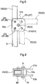
Fig. 8 is a left side view showing a supporting arrangement for the leading end side ROPS portion; and -
Fig. 9 is a plan view showing the supporting arrangement for the leading end side ROPS portion. - Embodiments of a riding-type mower related to the present invention will be described next with reference to the accompanying drawings.
- As shown in
Figs. 1 ,2 and3 , a direction [F] is defined to designate a front direction of a traveling vehicle body, a direction [B] is defined to designate a rear direction of the traveling vehicle body, a direction on the near side of the illustrations is defined to designate a left side direction of the traveling vehicle body, and a direction on the far side of the illustrations is defined to designate a right side direction of the traveling vehicle body, respectively. - As shown in
Fig. 1 , a riding-type mower includes a traveling vehicle body that mounts a pair of left andfront wheels 1 which are steerable and a pair of right and leftrear wheels 2 which are drivable. At a front portion of the traveling vehicle body, anengine section 3 is formed. An engine 4 is provided in theengine section 3. The traveling vehicle body travels as therear wheels 2 are driven by power of the engine 4. At a rear portion of the traveling vehicle body, adriving section 5 is formed. In thedriving section 5, there are provided a driver's seat 6 and asteering wheel 7. The traveling vehicle body is configured as a riding type as a person rides in thedriving section 5 and steers thefront wheels 1 by a rotational operation of thesteering wheel 7. At a rear portion of the traveling vehicle body, a rollover protection structure, also known asROPS 30, is provided. Amower unit 8 is supported at a portion of the traveling vehicle body between thefront wheels 1 and therear wheels 2. Themower unit 8 is supported by the traveling vehicle body via alink mechanism 9, so that in response to an elevating/lowering operation of thelink mechanism 9, themower unit 8 is operated up/down between a lowered work state and an elevated non-work state. To a rear portion of the traveling vehicle body, there is supported agrass collecting container 10. Aduct 11 is provided between themower unit 8 and thegrass collecting container 10. Theduct 11 extends between the right and leftrear wheels 2. - When the traveling vehicle body is caused to travel with setting the
mower unit 8 under the lowered work state, a grass cutting operation can be effected. Namely, in themower unit 8, arotary cutter blade 8a is rotatably driven by the power of the engine 4, so that grass is cut by therotary cutter blade 8a. Cut grass clippings are transported by conveying air current generated with the rotation of therotary cutter blade 8a through theduct 1 into thegrass collecting container 10 to be stored therein. - As shown in
Figs. 1 ,4 and5 , at a rear portion of the traveling vehicle body, there are provided a pair of right and left support frames 12 which extend along a vertical direction of the traveling vehicle body. The right and left support frames 12 are supported by avehicle body frame 17 via a firstjoint frame 13, right/left secondjoint frames 14, a thirdjoint frame 15 and right/left brackets 16. The firstjoint frame 13 joins lower portions of the right and left support frames 12. The thirdjoint frame 15 joins the right andleft brackets 16. The right/left secondjoint frame 14 join the firstjoint frame 13 to the thirdjoint frame 15. Eachbracket 16 is supported by thevehicle body frame 17 of the traveling vehicle boy via ajoint members 16b. - As shown in
Figs. 4 and5 ,support portions 18 are formed at right and left corners at the upper portion on the front end side of thegrass collecting container 10. Asupport shaft 19 extends between the right and leftsupport portions 18. The right and leftsupport portions 18 consist ofsupport members 18a fixed to the corner portions of thegrass collecting container 10 andpivot links 18b to whose free ends thesupport members 18a are coupled, respectively. Thegrass collecting container 10 is supported by the right and left support frames 12 via thesupport shaft 19 to be vertically pivotable about an axis P that extends along a lateral width direction of the traveling vehicle body. - A
coupling shaft 20 is operably coupled to the right and leftpivot links 18b, and in turn the right and leftpivot links 18b are operably coupled by thecoupling shaft 20 to be pivotable together about the axis P acting as the pivot. Right and leftlift cylinders 21 are operably coupled to thecoupling shaft 20. - As the
lift cylinders 21 are expanded/contracted, the pivot links 18b are pivoted up/down about the axis P by thelift cylinder 21, whereby thegrass collecting container 10 is pivoted up/down together with the pivot links 18b. In this way, thegrass collecting container 10 can be switched over in its posture between an elevated discharging posture (seeFig. 2 ) and a lowered storing posture (seeFig. 1 ). - The
support members 18a and the pivot links 18b are connected to each other via connecting bolts. When the connection between thesupport members 18a and thepivot links 18b is released, thegrass collecting container 10 can be detached from the support frames 12. - As shown in
Figs. 1 and3 , when a grass cutting operation is to be effected, thelift cylinder 21 will be operated in advance to the storage side to set thegrass collecting container 10 to the lowered storing posture. With this, thecollector 10 will assume a mounted posture with itsopening 10a facing forwardly of the vehicle body to face an exit of theduct 11, so that grass clippings cut by themower unit 8 can be collected in thegrass collecting container 10 to be stored therein. As shown inFig. 5 , ahook 22 is supported at a lower portion of thesupport frame 12 to be pivotally operable. When thegrass collecting container 10 is set to the lowered storing posture, with engagement of thehooks 22 with lock pins 23 of thegrass collecting container 10, thegrass collecting container 10 can be locked to the lowered storing posture by thehooks 22. - As shown in
Fig. 2 , when the grass clippings have been stored in thegrass collecting container 10, thelift cylinder 21 will be operated to the discharging side to set thegrass collecting container 10 to an elevated discharging posture. Then, the rear side of thegrass collecting container 10 will be elevated to assume a mounted posture with itsopening 18b being oriented downwards. Then, the glass clippings inside thegrass collecting container 10 will be allowed to drop under gravity to be discharged through theopening 10a. - As shown in
Fig. 1 andFig. 7 , theROPS 30 includes a pair of right and left base endside ROPS portions 31 and one leading endside ROPS portion 32. - As shown in
Figs. 5 and7 , a pair of right andleft brackets 16 are supported via thejoint members 16b by the right and left vehicle body frames 17 at the rear portions thereof. Thebrackets 16 are located more rearward than therear wheels 2. The lower end portions of the right and left base endside ROPS portions 31 are supported by thebrackets 16 at respective extension end portions thereof. The right and left base endside ROPS portions 31 are supported by the vehicle body frames 17 via thebrackets 16, respectively, under a vertically oriented posture extending along the vertical direction of the traveling vehicle body. - As shown in
Figs. 5-7 , eachjoint portion 31a is formed at the base end portion of the base endside ROPS portion 31. At an end portion of thebracket 16, there is provided a vertically orientedtubular holding portion 16a extending along the vertical direction of the traveling vehicle body. When thejoint portion 31a is inserted into the holdingportion 16a from above and then detachablyattachable stopper bolts 24 are attached to and between the holdingportion 16a and thejoint portion 31a, the base endside ROPS portion 31 is attachably/detachably supported by thebracket 16. When the right and left base endside ROPS portions 31 are attached/detached to/from thebrackets 16 at respective positions rearwardly of therear wheels 2, theROPS 30 can be attached/detached. - As shown in
Fig. 7 , the leading endside ROPS portion 32 includes a pair of right and leftstrut portions 33, and abeam portion 34 connected to leading ends of the pair of right and leftstrut portions 33. Thus, the leading endside ROPS portion 32 as a whole is configured in U-shape, with a distance between the pair of right and leftstrut portions 33 being greater than a lateral width W of the grass collecting container 10 (seeFig. 4 ). - As shown in
Figs. 7-9 , right and leftjoint portions 33a are formed at respective lower ends of the right and leftstrut portions 33. Right and leftsupport portions 31b are formed at respective upper ends of the right and left base endside ROPS portions 31. Between the right and leftsupport portions 31b, thejoint portions 33a are supported by the right and leftsupport portions 31b viasupport shafts 35, respectively. The leading endside ROPS portion 32 is supported by the right and leftsupport portions 31b at opposite ends thereof via thesupport shafts 35, to be pivotably operable about an axis X of therespective support shaft 35 extending in the lateral width direction of the traveling vehicle body. - As shown in
Fig. 8 , eachjoint portion 33a defines two lock holes 36. Whereas, eachsupport portion 31b defines four positioning holes 37. As shown inFig. 1 and also denoted with solid lines inFig. 8 , in response to a pivotal operation on the leading endside ROPS portion 32, when the two lock holes 36 are put into registry with afirst positioning hole 37a and asecond positioning hole 37b of the fourpositioning holes 37, the leading endside ROPS portion 32 will be raised relative to the base endside ROPS portions 31, thus assuming a use posture. In this case, adetachable lock pin 38 will be fitted to/between thefirst positioning hole 37a and one lock hole 36, and anotherdetachable lock pin 38 will be fitted to/between thesecond positioning hole 37b and the other lock hole 36. Whereby, the leading endside ROPS portion 32 can be locked under the use posture. - As shown in
Fig. 2 and also denoted with one-dot chain lines inFig. 8 , alternatively, in response to a pivotal operation on the leading endside ROPS portion 32, when the two lock holes 36 are put into registry with thesecond positioning hole 37b and athird positioning hole 37c of the fourpositioning holes 37, the leading endside ROPS portion 32 will be collapsed in the rearward direction of the traveling vehicle body relative to the base endside ROPS portions 31, thus assuming a first storage posture. In this case, adetachable lock pin 38 will be fitted to/between thesecond positioning hole 37b and one lock hole 36, and anotherdetachable lock pin 38 will be fitted to/between thethird positioning hole 37c and the other lock hole 36. Whereby, the leading endside ROPS portion 32 can be locked under the first storage posture. When the leading endside ROPS portion 32 is set to the first storage posture and thegrass collecting container 10 is set to the elevated discharging posture, afree end portion 10b of thegrass collecting container 10 enters the space between the right and leftstrut portions 33 and also the freeend side portion 10b of thegrass collecting container 10 will protrude upwards beyond the right and leftstrut portions 33. - As shown in
Fig. 3 and also denoted with two-dot chain lines inFig. 8 , still alternatively, in response to a pivotal operation on the leading endside ROPS portion 32, when the two lock holes 36 are put into registry with thethird positioning hole 37c and afourth positioning hole 37d of the fourpositioning holes 37, the leading endside ROPS portion 32 will be positioned along the base endside ROPS portions 31 on the rear side of the base endside ROPS portion 31, thus assuming a second storage posture which is more lowered than the first storage posture. In this case, adetachable lock pin 38 will be fitted to/between thethird positioning hole 37c and one lock hole 36, and anotherdetachable lock pin 38 will be fitted to/between thefourth positioning hole 37d and the other lock hole 36. With these, the leading endside ROPS portion 32 can be locked under the second storage posture. When the leading endside ROPS portion 32 is set to the second storage posture and thegrass collecting container 10 is set to the lowered storage posture, the leading endside ROPS portion 32 will be located more upwards than thegrass collecting container 10. - In the case of a work site where no obstacle is present above, by setting the leading end
side ROPS portion 32 to the use posture, a grass cutting operation can be carried out with increasing the height of theROPS 30. - On the other hand, in the case of a work site in vicinity of a tree, for instance, by setting the leading end
side ROPS portion 32 to the first storage posture, the height of theROPS 30 can be reduced, so that it becomes possible to carry out the cutting/mowing operation with readily avoiding accidental hooking of the tree with theROPS 30. Moreover, even when thegrass collecting container 10 is set to the elevated discharging posture, the freeend side portion 10b of thegrass collecting container 10 enters the space between the right and leftstrut portions 33 to prevent thegrass collecting container 10 from coming into contact with the leading endside ROPS portion 32. Consequently, with setting thegrass collecting container 10 to the elevated discharging posture, grass clippings can be discharged from thisgrass collecting container 10. - Further, by setting the leading end
side ROPS portion 32 to the second storage posture, a grass cutting operation can be carried out with securing a large empty space above thegrass collecting container 10 assuming the lowed storage posture. In this case, when grass clippings held inside thegrass collecting container 10 are to be discharged, by elevating the leading endside ROPS portion 32 to the first storage posture or the use posture, thegrass collecting container 10 can be elevated to its elevated discharging posture to allow the discharging. -
- (1) In the foregoing embodiment, there was disclosed the arrangement that allows posture change of the leading end
side ROPS portion 32 to the second storage posture. Alternatively, such posture change to the second storage posture can be disabled. - (2) In the foregoing embodiment, there was disclosed the example of providing the
brackets 16. Alternatively, it is possible to employ an arrangement in which the base endside ROPS portions 31 are supported directly to thevehicle body frame 17, with omission ofsuch brackets 16. - (3) In the foregoing embodiment, there was disclosed the example in which the
mower unit 8 is provided between thefront wheels 1 and therear wheels 2. Alternatively, themower unit 8 can be provided in any other location, such as a location forwardly of thefront wheels 1, etc. That is, the present invention is applicable not only to a mid-mount type disclosed in the above embodiment in which the mower unit is mounted between the front wheels and rear wheels, but applicable also to a front-mount type in which the mower unit is mounted forwardly of the front wheels.
Claims (4)
- A riding-type mower comprising:a traveling vehicle body having a driver's seat (6);a rollover protection structure (30) mounted at a rear portion of the traveling vehicle body;a mower unit (8) mounted on the traveling vehicle body;a grass collecting container (10) supported by the traveling vehicle body at a rear portion thereof and configured to store grass clippings cut by the mower unit (8);the grass collecting container (10) being supported by the traveling vehicle body to be switchably and pivotally elevated/lowered between an elevated discharging posture realized when the container (10) is pivotally elevated about a pivot axis (P) disposed upwardly of the grass collecting container and extending along a lateral width direction of the traveling vehicle body, and a lowered storing posture realized when the container (10) is pivotally lowered about the pivot axis (P); andthe rollover protection structure (30) including a pair of right and left base end side rollover protection structure portions (31) protruding upwards from the traveling vehicle body, and a leading end side rollover protection structure portion (32) which is supported to the leading end portions of the pair of right and left base end side rollover protection structure portions (31) to be pivotally raised/collapsed, and is switchable between a use posture in which the leading end side rollover protection structure portion is raised relative to the base end side rollover protection structure portions (31) and a storage posture in which the leading end side rollover protection structure portion (32) is collapsed to the rear side of the traveling vehicle body relative to the base end side rollover protection structure portions (31);wherein the leading end side rollover protection structure portion (32) includes a pair of right and left strut portions (33) having base end portions supported at the leading end portions of the pair of right and left base end side rollover protection structure portions (31), and a beam portion (34) connected to leading ends of the pair of right and left strut portions (33);wherein a distance (D) between the pair of right and left strut portions (33) is greater than a lateral width (W) of the grass collecting container (10); andwherein a free end side of the grass collecting container (10) enters a space between the pair of right and left strut portions (33) when the leading end side rollover protection structure portion (32) assumes the storage posture and also the grass collecting container (10) assumes the elevated discharging posture.
- The riding-type mower according to claim 1, wherein the leading end side rollover protection structure portion (32) is supported to be posture-changeable to a second storage posture in which the leading end side rollover protection structure portion (32) is further pivotally lowered than the storage posture and is located on the rear side of the pair of right and left base end side rollover protection structure portions (31) along the base end side rollover protection structure portions (31).
- The riding-type mower according to claim 2, wherein the leading end side rollover protection structure portion (32) is located higher than the grass collecting container (10) when the grass collecting container (10) is set to the lowered storage posture and also the leading end side rollover protection structure portion (32) assumes the second storage posture.
- The riding-type mower of any one of preceding claims, wherein:the mower further comprises a pair of right and left brackets (16) that are attached to the traveling vehicle body and that support the pair of right and left base end side rollover protection structure portions (31) detachably/attachably and independently of each other; andwherein the pair of right and left brackets (16) include a holding portion (16a) configured to hold joint portions (31a) of the base end side rollover protection structure portions (31) when the joint portions (31a) are inserted into the pair of right and left brackets from above.
Applications Claiming Priority (1)
| Application Number | Priority Date | Filing Date | Title |
|---|---|---|---|
| JP2017032214A JP6815223B2 (en) | 2017-02-23 | 2017-02-23 | Riding mower |
Publications (2)
| Publication Number | Publication Date |
|---|---|
| EP3366105A1 true EP3366105A1 (en) | 2018-08-29 |
| EP3366105B1 EP3366105B1 (en) | 2020-03-04 |
Family
ID=60515233
Family Applications (1)
| Application Number | Title | Priority Date | Filing Date |
|---|---|---|---|
| EP17204471.1A Active EP3366105B1 (en) | 2017-02-23 | 2017-11-29 | Riding-type mower |
Country Status (2)
| Country | Link |
|---|---|
| EP (1) | EP3366105B1 (en) |
| JP (1) | JP6815223B2 (en) |
Families Citing this family (1)
| Publication number | Priority date | Publication date | Assignee | Title |
|---|---|---|---|---|
| JP7239748B2 (en) * | 2018-10-10 | 2023-03-14 | 株式会社クボタ | riding lawn mower |
Citations (2)
| Publication number | Priority date | Publication date | Assignee | Title |
|---|---|---|---|---|
| JP2010178635A (en) | 2009-02-03 | 2010-08-19 | Kubota Corp | Riding type mower |
| EP2870855A1 (en) * | 2013-11-11 | 2015-05-13 | Kubota Corporation | Riding-type mower |
Family Cites Families (9)
| Publication number | Priority date | Publication date | Assignee | Title |
|---|---|---|---|---|
| JP3289327B2 (en) * | 1992-07-31 | 2002-06-04 | 井関農機株式会社 | Tractor safety frame |
| JP3830454B2 (en) * | 2003-02-10 | 2006-10-04 | 株式会社クボタ | Riding mower |
| JP4439420B2 (en) * | 2005-03-22 | 2010-03-24 | 株式会社クボタ | Mower |
| US7971904B2 (en) * | 2006-06-20 | 2011-07-05 | Deere & Company | Rollover protection system |
| JP2008062743A (en) * | 2006-09-06 | 2008-03-21 | Kubota Corp | Agricultural tractor frame structure |
| JP5060466B2 (en) * | 2008-12-24 | 2012-10-31 | 株式会社クボタ | Mower collecting equipment |
| JP5422449B2 (en) * | 2010-03-11 | 2014-02-19 | 三菱農機株式会社 | Fall protection frame for working vehicles |
| JP2015082988A (en) * | 2013-10-25 | 2015-04-30 | 井関農機株式会社 | Drug spray vehicle |
| JP6804184B2 (en) * | 2015-05-27 | 2020-12-23 | 井関農機株式会社 | Riding lawn mower |
-
2017
- 2017-02-23 JP JP2017032214A patent/JP6815223B2/en active Active
- 2017-11-29 EP EP17204471.1A patent/EP3366105B1/en active Active
Patent Citations (2)
| Publication number | Priority date | Publication date | Assignee | Title |
|---|---|---|---|---|
| JP2010178635A (en) | 2009-02-03 | 2010-08-19 | Kubota Corp | Riding type mower |
| EP2870855A1 (en) * | 2013-11-11 | 2015-05-13 | Kubota Corporation | Riding-type mower |
Also Published As
| Publication number | Publication date |
|---|---|
| JP6815223B2 (en) | 2021-01-20 |
| EP3366105B1 (en) | 2020-03-04 |
| JP2018134055A (en) | 2018-08-30 |
Similar Documents
| Publication | Publication Date | Title |
|---|---|---|
| US7992373B2 (en) | Lawn mower with grass collecting unit support | |
| US7971904B2 (en) | Rollover protection system | |
| US6237313B1 (en) | Grass catcher support assembly for reel mower cutting unit | |
| CN106686971A (en) | Wheeled lawnmower for walking driver | |
| KR102162051B1 (en) | Riding type mower | |
| EP3366105B1 (en) | Riding-type mower | |
| EP3440916B1 (en) | Triplex greensmower lift system | |
| US8393136B1 (en) | Concave deck flexible hitch cutter | |
| CA1282038C (en) | Device for removably attaching front loader to vehicle | |
| JP2002101722A (en) | Riding mower | |
| EP3440915B1 (en) | Triplex greensmower open foot platform | |
| JP2001352822A (en) | Hay harvesting machine having at least one rake wheel jointed to supporting arm | |
| US20030024223A1 (en) | Electric vehicle and reel mower gang | |
| JP4601004B2 (en) | Riding mower | |
| US3455406A (en) | Agricultural machine with alternate caster wheel positions | |
| EP0192330A1 (en) | Grass cutting attachment for tractor | |
| JP2018102238A (en) | Riding lawn mower | |
| JP7192607B2 (en) | riding lawn mower | |
| JP3858424B2 (en) | Front mower for tractor | |
| EP3646695B1 (en) | Triplex greensmower open foot platform cover | |
| JPH1075623A (en) | Tractor offset mower | |
| JPH1033038A (en) | Tractor mower fuel tank mounting device | |
| CA2530109C (en) | Crop picking head with road travel support device | |
| JP4601003B2 (en) | Connecting device for grass-collecting device of riding type mower | |
| JP3935813B2 (en) | lawn mower |
Legal Events
| Date | Code | Title | Description |
|---|---|---|---|
| PUAI | Public reference made under article 153(3) epc to a published international application that has entered the european phase |
Free format text: ORIGINAL CODE: 0009012 |
|
| STAA | Information on the status of an ep patent application or granted ep patent |
Free format text: STATUS: THE APPLICATION HAS BEEN PUBLISHED |
|
| AK | Designated contracting states |
Kind code of ref document: A1 Designated state(s): AL AT BE BG CH CY CZ DE DK EE ES FI FR GB GR HR HU IE IS IT LI LT LU LV MC MK MT NL NO PL PT RO RS SE SI SK SM TR |
|
| AX | Request for extension of the european patent |
Extension state: BA ME |
|
| STAA | Information on the status of an ep patent application or granted ep patent |
Free format text: STATUS: REQUEST FOR EXAMINATION WAS MADE |
|
| 17P | Request for examination filed |
Effective date: 20190227 |
|
| RBV | Designated contracting states (corrected) |
Designated state(s): AL AT BE BG CH CY CZ DE DK EE ES FI FR GB GR HR HU IE IS IT LI LT LU LV MC MK MT NL NO PL PT RO RS SE SI SK SM TR |
|
| GRAP | Despatch of communication of intention to grant a patent |
Free format text: ORIGINAL CODE: EPIDOSNIGR1 |
|
| STAA | Information on the status of an ep patent application or granted ep patent |
Free format text: STATUS: GRANT OF PATENT IS INTENDED |
|
| INTG | Intention to grant announced |
Effective date: 20190923 |
|
| GRAS | Grant fee paid |
Free format text: ORIGINAL CODE: EPIDOSNIGR3 |
|
| GRAA | (expected) grant |
Free format text: ORIGINAL CODE: 0009210 |
|
| STAA | Information on the status of an ep patent application or granted ep patent |
Free format text: STATUS: THE PATENT HAS BEEN GRANTED |
|
| AK | Designated contracting states |
Kind code of ref document: B1 Designated state(s): AL AT BE BG CH CY CZ DE DK EE ES FI FR GB GR HR HU IE IS IT LI LT LU LV MC MK MT NL NO PL PT RO RS SE SI SK SM TR |
|
| REG | Reference to a national code |
Ref country code: GB Ref legal event code: FG4D |
|
| REG | Reference to a national code |
Ref country code: CH Ref legal event code: EP |
|
| REG | Reference to a national code |
Ref country code: AT Ref legal event code: REF Ref document number: 1239336 Country of ref document: AT Kind code of ref document: T Effective date: 20200315 |
|
| REG | Reference to a national code |
Ref country code: DE Ref legal event code: R096 Ref document number: 602017012529 Country of ref document: DE |
|
| REG | Reference to a national code |
Ref country code: IE Ref legal event code: FG4D |
|
| PG25 | Lapsed in a contracting state [announced via postgrant information from national office to epo] |
Ref country code: FI Free format text: LAPSE BECAUSE OF FAILURE TO SUBMIT A TRANSLATION OF THE DESCRIPTION OR TO PAY THE FEE WITHIN THE PRESCRIBED TIME-LIMIT Effective date: 20200304 Ref country code: NO Free format text: LAPSE BECAUSE OF FAILURE TO SUBMIT A TRANSLATION OF THE DESCRIPTION OR TO PAY THE FEE WITHIN THE PRESCRIBED TIME-LIMIT Effective date: 20200604 Ref country code: RS Free format text: LAPSE BECAUSE OF FAILURE TO SUBMIT A TRANSLATION OF THE DESCRIPTION OR TO PAY THE FEE WITHIN THE PRESCRIBED TIME-LIMIT Effective date: 20200304 |
|
| REG | Reference to a national code |
Ref country code: NL Ref legal event code: MP Effective date: 20200304 |
|
| PG25 | Lapsed in a contracting state [announced via postgrant information from national office to epo] |
Ref country code: GR Free format text: LAPSE BECAUSE OF FAILURE TO SUBMIT A TRANSLATION OF THE DESCRIPTION OR TO PAY THE FEE WITHIN THE PRESCRIBED TIME-LIMIT Effective date: 20200605 Ref country code: HR Free format text: LAPSE BECAUSE OF FAILURE TO SUBMIT A TRANSLATION OF THE DESCRIPTION OR TO PAY THE FEE WITHIN THE PRESCRIBED TIME-LIMIT Effective date: 20200304 Ref country code: SE Free format text: LAPSE BECAUSE OF FAILURE TO SUBMIT A TRANSLATION OF THE DESCRIPTION OR TO PAY THE FEE WITHIN THE PRESCRIBED TIME-LIMIT Effective date: 20200304 Ref country code: LV Free format text: LAPSE BECAUSE OF FAILURE TO SUBMIT A TRANSLATION OF THE DESCRIPTION OR TO PAY THE FEE WITHIN THE PRESCRIBED TIME-LIMIT Effective date: 20200304 Ref country code: BG Free format text: LAPSE BECAUSE OF FAILURE TO SUBMIT A TRANSLATION OF THE DESCRIPTION OR TO PAY THE FEE WITHIN THE PRESCRIBED TIME-LIMIT Effective date: 20200604 |
|
| REG | Reference to a national code |
Ref country code: LT Ref legal event code: MG4D |
|
| PG25 | Lapsed in a contracting state [announced via postgrant information from national office to epo] |
Ref country code: NL Free format text: LAPSE BECAUSE OF FAILURE TO SUBMIT A TRANSLATION OF THE DESCRIPTION OR TO PAY THE FEE WITHIN THE PRESCRIBED TIME-LIMIT Effective date: 20200304 |
|
| PG25 | Lapsed in a contracting state [announced via postgrant information from national office to epo] |
Ref country code: PT Free format text: LAPSE BECAUSE OF FAILURE TO SUBMIT A TRANSLATION OF THE DESCRIPTION OR TO PAY THE FEE WITHIN THE PRESCRIBED TIME-LIMIT Effective date: 20200729 Ref country code: ES Free format text: LAPSE BECAUSE OF FAILURE TO SUBMIT A TRANSLATION OF THE DESCRIPTION OR TO PAY THE FEE WITHIN THE PRESCRIBED TIME-LIMIT Effective date: 20200304 Ref country code: RO Free format text: LAPSE BECAUSE OF FAILURE TO SUBMIT A TRANSLATION OF THE DESCRIPTION OR TO PAY THE FEE WITHIN THE PRESCRIBED TIME-LIMIT Effective date: 20200304 Ref country code: CZ Free format text: LAPSE BECAUSE OF FAILURE TO SUBMIT A TRANSLATION OF THE DESCRIPTION OR TO PAY THE FEE WITHIN THE PRESCRIBED TIME-LIMIT Effective date: 20200304 Ref country code: SM Free format text: LAPSE BECAUSE OF FAILURE TO SUBMIT A TRANSLATION OF THE DESCRIPTION OR TO PAY THE FEE WITHIN THE PRESCRIBED TIME-LIMIT Effective date: 20200304 Ref country code: EE Free format text: LAPSE BECAUSE OF FAILURE TO SUBMIT A TRANSLATION OF THE DESCRIPTION OR TO PAY THE FEE WITHIN THE PRESCRIBED TIME-LIMIT Effective date: 20200304 Ref country code: LT Free format text: LAPSE BECAUSE OF FAILURE TO SUBMIT A TRANSLATION OF THE DESCRIPTION OR TO PAY THE FEE WITHIN THE PRESCRIBED TIME-LIMIT Effective date: 20200304 Ref country code: IS Free format text: LAPSE BECAUSE OF FAILURE TO SUBMIT A TRANSLATION OF THE DESCRIPTION OR TO PAY THE FEE WITHIN THE PRESCRIBED TIME-LIMIT Effective date: 20200704 Ref country code: SK Free format text: LAPSE BECAUSE OF FAILURE TO SUBMIT A TRANSLATION OF THE DESCRIPTION OR TO PAY THE FEE WITHIN THE PRESCRIBED TIME-LIMIT Effective date: 20200304 |
|
| REG | Reference to a national code |
Ref country code: AT Ref legal event code: MK05 Ref document number: 1239336 Country of ref document: AT Kind code of ref document: T Effective date: 20200304 |
|
| REG | Reference to a national code |
Ref country code: DE Ref legal event code: R097 Ref document number: 602017012529 Country of ref document: DE |
|
| PLBE | No opposition filed within time limit |
Free format text: ORIGINAL CODE: 0009261 |
|
| STAA | Information on the status of an ep patent application or granted ep patent |
Free format text: STATUS: NO OPPOSITION FILED WITHIN TIME LIMIT |
|
| PG25 | Lapsed in a contracting state [announced via postgrant information from national office to epo] |
Ref country code: IT Free format text: LAPSE BECAUSE OF FAILURE TO SUBMIT A TRANSLATION OF THE DESCRIPTION OR TO PAY THE FEE WITHIN THE PRESCRIBED TIME-LIMIT Effective date: 20200304 Ref country code: AT Free format text: LAPSE BECAUSE OF FAILURE TO SUBMIT A TRANSLATION OF THE DESCRIPTION OR TO PAY THE FEE WITHIN THE PRESCRIBED TIME-LIMIT Effective date: 20200304 Ref country code: DK Free format text: LAPSE BECAUSE OF FAILURE TO SUBMIT A TRANSLATION OF THE DESCRIPTION OR TO PAY THE FEE WITHIN THE PRESCRIBED TIME-LIMIT Effective date: 20200304 |
|
| 26N | No opposition filed |
Effective date: 20201207 |
|
| PG25 | Lapsed in a contracting state [announced via postgrant information from national office to epo] |
Ref country code: PL Free format text: LAPSE BECAUSE OF FAILURE TO SUBMIT A TRANSLATION OF THE DESCRIPTION OR TO PAY THE FEE WITHIN THE PRESCRIBED TIME-LIMIT Effective date: 20200304 Ref country code: SI Free format text: LAPSE BECAUSE OF FAILURE TO SUBMIT A TRANSLATION OF THE DESCRIPTION OR TO PAY THE FEE WITHIN THE PRESCRIBED TIME-LIMIT Effective date: 20200304 |
|
| REG | Reference to a national code |
Ref country code: DE Ref legal event code: R119 Ref document number: 602017012529 Country of ref document: DE |
|
| PG25 | Lapsed in a contracting state [announced via postgrant information from national office to epo] |
Ref country code: MC Free format text: LAPSE BECAUSE OF FAILURE TO SUBMIT A TRANSLATION OF THE DESCRIPTION OR TO PAY THE FEE WITHIN THE PRESCRIBED TIME-LIMIT Effective date: 20200304 |
|
| REG | Reference to a national code |
Ref country code: CH Ref legal event code: PL |
|
| PG25 | Lapsed in a contracting state [announced via postgrant information from national office to epo] |
Ref country code: LU Free format text: LAPSE BECAUSE OF NON-PAYMENT OF DUE FEES Effective date: 20201129 |
|
| REG | Reference to a national code |
Ref country code: BE Ref legal event code: MM Effective date: 20201130 |
|
| PG25 | Lapsed in a contracting state [announced via postgrant information from national office to epo] |
Ref country code: CH Free format text: LAPSE BECAUSE OF NON-PAYMENT OF DUE FEES Effective date: 20201130 Ref country code: LI Free format text: LAPSE BECAUSE OF NON-PAYMENT OF DUE FEES Effective date: 20201130 |
|
| REG | Reference to a national code |
Ref country code: IE Ref legal event code: MM4A |
|
| PG25 | Lapsed in a contracting state [announced via postgrant information from national office to epo] |
Ref country code: IE Free format text: LAPSE BECAUSE OF NON-PAYMENT OF DUE FEES Effective date: 20201129 |
|
| PG25 | Lapsed in a contracting state [announced via postgrant information from national office to epo] |
Ref country code: DE Free format text: LAPSE BECAUSE OF NON-PAYMENT OF DUE FEES Effective date: 20210601 |
|
| PG25 | Lapsed in a contracting state [announced via postgrant information from national office to epo] |
Ref country code: TR Free format text: LAPSE BECAUSE OF FAILURE TO SUBMIT A TRANSLATION OF THE DESCRIPTION OR TO PAY THE FEE WITHIN THE PRESCRIBED TIME-LIMIT Effective date: 20200304 Ref country code: MT Free format text: LAPSE BECAUSE OF FAILURE TO SUBMIT A TRANSLATION OF THE DESCRIPTION OR TO PAY THE FEE WITHIN THE PRESCRIBED TIME-LIMIT Effective date: 20200304 Ref country code: CY Free format text: LAPSE BECAUSE OF FAILURE TO SUBMIT A TRANSLATION OF THE DESCRIPTION OR TO PAY THE FEE WITHIN THE PRESCRIBED TIME-LIMIT Effective date: 20200304 |
|
| PG25 | Lapsed in a contracting state [announced via postgrant information from national office to epo] |
Ref country code: MK Free format text: LAPSE BECAUSE OF FAILURE TO SUBMIT A TRANSLATION OF THE DESCRIPTION OR TO PAY THE FEE WITHIN THE PRESCRIBED TIME-LIMIT Effective date: 20200304 Ref country code: AL Free format text: LAPSE BECAUSE OF FAILURE TO SUBMIT A TRANSLATION OF THE DESCRIPTION OR TO PAY THE FEE WITHIN THE PRESCRIBED TIME-LIMIT Effective date: 20200304 |
|
| GBPC | Gb: european patent ceased through non-payment of renewal fee |
Effective date: 20211129 |
|
| PG25 | Lapsed in a contracting state [announced via postgrant information from national office to epo] |
Ref country code: BE Free format text: LAPSE BECAUSE OF NON-PAYMENT OF DUE FEES Effective date: 20201130 |
|
| PG25 | Lapsed in a contracting state [announced via postgrant information from national office to epo] |
Ref country code: GB Free format text: LAPSE BECAUSE OF NON-PAYMENT OF DUE FEES Effective date: 20211129 |
|
| PGFP | Annual fee paid to national office [announced via postgrant information from national office to epo] |
Ref country code: FR Payment date: 20250930 Year of fee payment: 9 |