EP3366079B1 - Radiation pumped heater/heating element - Google Patents
Radiation pumped heater/heating element Download PDFInfo
- Publication number
- EP3366079B1 EP3366079B1 EP16801574.1A EP16801574A EP3366079B1 EP 3366079 B1 EP3366079 B1 EP 3366079B1 EP 16801574 A EP16801574 A EP 16801574A EP 3366079 B1 EP3366079 B1 EP 3366079B1
- Authority
- EP
- European Patent Office
- Prior art keywords
- fiber
- holders
- optical fiber
- heated
- heater
- Prior art date
- Legal status (The legal status is an assumption and is not a legal conclusion. Google has not performed a legal analysis and makes no representation as to the accuracy of the status listed.)
- Active
Links
Images

Classifications
-
- C—CHEMISTRY; METALLURGY
- C03—GLASS; MINERAL OR SLAG WOOL
- C03B—MANUFACTURE, SHAPING, OR SUPPLEMENTARY PROCESSES
- C03B37/00—Manufacture or treatment of flakes, fibres, or filaments from softened glass, minerals, or slags
- C03B37/01—Manufacture of glass fibres or filaments
- C03B37/02—Manufacture of glass fibres or filaments by drawing or extruding, e.g. direct drawing of molten glass from nozzles; Cooling fins therefor
- C03B37/025—Manufacture of glass fibres or filaments by drawing or extruding, e.g. direct drawing of molten glass from nozzles; Cooling fins therefor from reheated softened tubes, rods, fibres or filaments, e.g. drawing fibres from preforms
- C03B37/029—Furnaces therefor
-
- H—ELECTRICITY
- H05—ELECTRIC TECHNIQUES NOT OTHERWISE PROVIDED FOR
- H05B—ELECTRIC HEATING; ELECTRIC LIGHT SOURCES NOT OTHERWISE PROVIDED FOR; CIRCUIT ARRANGEMENTS FOR ELECTRIC LIGHT SOURCES, IN GENERAL
- H05B3/00—Ohmic-resistance heating
- H05B3/0033—Heating devices using lamps
- H05B3/0038—Heating devices using lamps for industrial applications
-
- B—PERFORMING OPERATIONS; TRANSPORTING
- B23—MACHINE TOOLS; METAL-WORKING NOT OTHERWISE PROVIDED FOR
- B23K—SOLDERING OR UNSOLDERING; WELDING; CLADDING OR PLATING BY SOLDERING OR WELDING; CUTTING BY APPLYING HEAT LOCALLY, e.g. FLAME CUTTING; WORKING BY LASER BEAM
- B23K26/00—Working by laser beam, e.g. welding, cutting or boring
- B23K26/50—Working by transmitting the laser beam through or within the workpiece
-
- C—CHEMISTRY; METALLURGY
- C03—GLASS; MINERAL OR SLAG WOOL
- C03B—MANUFACTURE, SHAPING, OR SUPPLEMENTARY PROCESSES
- C03B23/00—Re-forming shaped glass
- C03B23/04—Re-forming tubes or rods
- C03B23/043—Heating devices specially adapted for re-forming tubes or rods in general, e.g. burners
-
- C—CHEMISTRY; METALLURGY
- C03—GLASS; MINERAL OR SLAG WOOL
- C03B—MANUFACTURE, SHAPING, OR SUPPLEMENTARY PROCESSES
- C03B37/00—Manufacture or treatment of flakes, fibres, or filaments from softened glass, minerals, or slags
- C03B37/10—Non-chemical treatment
- C03B37/14—Re-forming fibres or filaments, i.e. changing their shape
- C03B37/15—Re-forming fibres or filaments, i.e. changing their shape with heat application, e.g. for making optical fibres
-
- H—ELECTRICITY
- H05—ELECTRIC TECHNIQUES NOT OTHERWISE PROVIDED FOR
- H05B—ELECTRIC HEATING; ELECTRIC LIGHT SOURCES NOT OTHERWISE PROVIDED FOR; CIRCUIT ARRANGEMENTS FOR ELECTRIC LIGHT SOURCES, IN GENERAL
- H05B1/00—Details of electric heating devices
- H05B1/02—Automatic switching arrangements specially adapted to apparatus ; Control of heating devices
- H05B1/0227—Applications
- H05B1/023—Industrial applications
-
- C—CHEMISTRY; METALLURGY
- C03—GLASS; MINERAL OR SLAG WOOL
- C03B—MANUFACTURE, SHAPING, OR SUPPLEMENTARY PROCESSES
- C03B2205/00—Fibre drawing or extruding details
- C03B2205/20—Irradiation of the base fibre during drawing to modify waveguide properties
Definitions
- the present invention relates generally to heating elements, and particularly to steady-state heaters useful in certain processes, such as reducing diameters of optical fibers.
- Micro heat sources play a major role in fiber optics and glass processing. In general they need to provide a steady, clean and controllable heating zone at temperatures that approach 2000°C.
- An electric filament may be shaped to produce a highly uniform heating zone around the glass object. Its temperature can also be controlled by controlling the voltage and current that flows through it. Unfortunately, the commonly used electric filament needs to be kept in an inert environment and its lifetime is limited to about tens of minutes at working conditions. Moreover, electric filaments tend to contaminate the processed glass to some extent.
- Arc discharge can provide high temperatures and be used to process large diameter fibers yet it suffers from long term stability issues and is not appropriate for delicate and thin adiabatic structures. It can also contribute to contamination as particles from the electrode collide with the processed glass.
- Delicate and low-loss components with diameters of a few microns may be produced and processed using a gas flame torch.
- This heating source in general is less appropriate for large and non-symmetric glass objects mainly due to the relatively large heating zone and flame instability. Furthermore, OH contaminations are almost unavoidable when a gas flame is used. For some applications such contaminations are not desirable.
- US 6 543 256 BA discloses an optical fiber coupler making apparatus which makes an optical fiber coupler by thermally fusing a plurality of optical fibers together by use of a heater and then elongating the thermally fused part.
- US 5 931 983 A discloses fused bioconical tapered couplers formed from the pulling of heated optical fibers that have controllable coupling ratios by dynamically adjusting the heat intensity and pull speed during fabrication.
- the present invention seeks to provide a radiation pumped heater, as is described more in detail hereinbelow.
- the radiation pumped heater directs thermal radiation to a highly stable platform (e.g., ceramic platform), which absorbs the radiation, causing its temperature to rise.
- the heated platform functions as a heat capacitor, contributing to the process stability, and also functions as a clean, long-lived heat source. This concept allows flexibility in the processing techniques and is appropriate for processing both large fibers as well as delicate components of sub-micron diameters.
- the radiation pumped heater is not just applicable for fiber and glass processing, but may also be used for other processes that require a steady and clean heat source.
- a ceramic substrate is used as a heater. Electromagnetic radiation from an external source is absorbed in the substrate. Since ceramics typically have poor thermal conductivity, the absorbed power is poorly dissipated by heat conduction. This in turn allows the buildup of high temperatures with relatively low incident powers. Furthermore, since the electromagnetic power can be delivered by a laser beam having high brightness, the heat source can be intense and small. Some ceramics such as zirconia (zirconium dioxide Zr0 2 ) have melting points at the range of 2500°C and higher and are inert. The thermal conductivity of Zr0 2 is in the range of 1.8-2.2 Winn-K.
- the radiation source and the delivery technique can allow the formation of an effective heater or heating element in which the high ceramic temperature is dissipated to the surrounding as black body radiation and by convection, similarly to a standard electro-resistant heating element.
- an effective heater or heating element in which the high ceramic temperature is dissipated to the surrounding as black body radiation and by convection, similarly to a standard electro-resistant heating element.
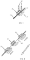
- FIG. 1 illustrates a radiation pumped heater, in accordance with a non-limiting embodiment of the invention, used for optical fiber processing.
- a ceramic substrate 10 such as a zirconia ceramic
- the laser beam 12 is strongly absorbed near the zirconia upper face which in turn rapidly heats until reaching a steady state.
- a few watt CO 2 laser having a beam diameter of the order of one mm, can easily raise the laser-zirconia interaction zone to temperatures acceding 2000°C in an atmospheric environment.
- An optical fiber 14 is heated by conduction and radiation emitted from the ceramic substrate 10. The ceramic substrate can maintain this high temperature for an hour or more.
- the ceramic substrate 10 may be quite porous, and the volume of the pores may constitute 90% or more of the total volume. Such porosity lowers the thermal conductivity (the pores are basically air pockets and air has very poor thermal conductivity). The high porosity also affects the thermal shock resistance of the ceramic substrate 10. It has been found that the zirconia substrate behaved well in tests even when heated rapidly,
- a ceramic substrate 16 is formed with an internal cavity 18, thus forming a ceramic furnace.
- the laser beam 12 impinges upon the cavity 18 and heats up the ceramic furnace.
- the furnace may be used for heating optical fiber 14 in the treatment and production of fiber optic devices, such as but not limited to, tapers, couplers and combiners.
- Fig. 3 illustrates a radiation pumped heater 25 that includes a ceramic substrate 20 with a depression 22 in which the fiber 14 is placed.
- the substrate 20 is heated by a pair of laser beams 12 symmetrically on opposite sides of the fiber 14.
- the laser beam impinges on the optical fiber
- Fig. 3 the beams do not impinge on the fiber.
- Fig. 4 illustrates processing the optical fiber 14 with the radiation pumped heater 25, in accordance with a non-limiting embodiment of the invention.
- Two opposite ends of the fiber 14 are held by holding elements 30, such as clamps.
- the middle portion of the fiber is heated by the heater 25 of Fig. 3 .
- the holding elements 30 are moved in opposite directions; this causes the middle portion of the fiber to be drawn thinner to a reduced diameter.
- the process can be carefully and precisely controlled to achieve precise diameters. Heating over the reduced diameter portion should be done uniformly.
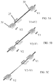
- Figs. 5A-5C illustrate processing the optical fiber 14 with the radiation pumped heater 25, in accordance with another non-limiting embodiment of the invention.
- two opposite ends of the fiber 14 are held by holding elements 30 and the middle portion of the fiber is heated by heater 25.
- the holding elements 30 are initially moved in the same direction at the same velocity ( Fig. 5A ).
- the proximal holder 30 that feeds the fiber to heater 25
- Fig. 5B This causes the middle portion of the fiber to be drawn thinner to a reduced diameter.
- the velocity of the proximal holder 30 can be modified, for example, to match that of the distal holder 30 so that the holders move at the same velocity ( Fig. 5C ); or alternatively moved at different speeds.
- the diameter and length of the fiber portion with the reduced diameter process can be carefully and precisely controlled, depending on the relative velocities of the holders, temperature and fiber properties, among other factors.
- the method of Fig. 4 (holding elements 30 are moved in opposite directions) is applicable for thicker fibers than the method of Fig. 5 .
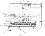
- FIG. 6 illustrates apparatus 60 for processing optical fibers, in accordance with a non-limiting embodiment of the invention.
- Apparatus 60 includes holders 65 and 66 for holding an optical fiber 14.
- Motors or actuators 63 and 64 control and establish the relative position of holders 65 and 66, respectively.
- Motors 63 and 64 and holders 65 and 66 are all mounted on a moving table for movement in the x- and z-axes.
- the moving table may include a base which is moved by a motor or actuator 61 along the x-axis and another base which is moved by a motor or actuator 62 along the z-axis.
- the central portion of the fiber is heated by a radiation pumped heater 67.
- Camera(s) 68 provide visual monitoring and measurement of the heating and drawing process.
- a laser 76 e.g., CO 2 laser
- the beam passes from the telescope 70 to a cylindrical lens 71, and is then reflected by a mirror 74 to the work area of the fiber.
- a beam splitting polarizer 72 splits the beam and one of the beams is directed by another mirror 73 to the work area. Both beams that are directed to the work area may pass through a spherical mirror 69.
- the beams are directed on the ceramic substrate of heater 67 on opposite sides of the fiber 14 (or on the fiber), as described above.
- the telescope 70 is used to control the spot size of the beam on the ceramic and/or fiber.
- a controller 79 may be provided for controlling the various elements of the apparatus for controlling the process to desired parameters.
- the invention has been described above for use with reducing the diameter of an optical fiber.
- the invention may also be used for thinning and melting more than one fiber and fibers that have different mechanical and/or optical properties.
- the invention may also be used for producing optical couplers and other optical devices, and for thinning tubes and other structures.
Landscapes
- Engineering & Computer Science (AREA)
- Chemical & Material Sciences (AREA)
- Organic Chemistry (AREA)
- Materials Engineering (AREA)
- Optics & Photonics (AREA)
- Physics & Mathematics (AREA)
- Manufacturing & Machinery (AREA)
- Geochemistry & Mineralogy (AREA)
- General Life Sciences & Earth Sciences (AREA)
- Life Sciences & Earth Sciences (AREA)
- Chemical Kinetics & Catalysis (AREA)
- General Chemical & Material Sciences (AREA)
- Oil, Petroleum & Natural Gas (AREA)
- Plasma & Fusion (AREA)
- Mechanical Engineering (AREA)
- Laser Beam Processing (AREA)
Description
- The present invention relates generally to heating elements, and particularly to steady-state heaters useful in certain processes, such as reducing diameters of optical fibers.
- Micro heat sources play a major role in fiber optics and glass processing. In general they need to provide a steady, clean and controllable heating zone at temperatures that approach 2000°C.
- At present, there are four major techniques for achieving the required heat and which are used in commercial machines:
- flame (usually hydrogen flame)
- electric filament
- arc discharge
- direct laser absorption in the fiber or glass object.
- Each technique has its advantages and disadvantages such that one technique may be suitable for certain processing conditions and not for others. Direct absorption of laser energy in the glass provides the cleanest heating source; however, due to high and dynamic heat convection to the surroundings, it is difficult to precisely and uniformly heat objects with diameters of a few microns. Moreover, some processes require very stable heating sources, which are difficult to produce with conventional laser and delivery optics.
- An electric filament may be shaped to produce a highly uniform heating zone around the glass object. Its temperature can also be controlled by controlling the voltage and current that flows through it. Unfortunately, the commonly used electric filament needs to be kept in an inert environment and its lifetime is limited to about tens of minutes at working conditions. Moreover, electric filaments tend to contaminate the processed glass to some extent.
- Arc discharge can provide high temperatures and be used to process large diameter fibers yet it suffers from long term stability issues and is not appropriate for delicate and thin adiabatic structures. It can also contribute to contamination as particles from the electrode collide with the processed glass.
- Delicate and low-loss components with diameters of a few microns may be produced and processed using a gas flame torch. This heating source in general is less appropriate for large and non-symmetric glass objects mainly due to the relatively large heating zone and flame instability. Furthermore, OH contaminations are almost unavoidable when a gas flame is used. For some applications such contaminations are not desirable.
-
US 6 543 256 BA discloses an optical fiber coupler making apparatus which makes an optical fiber coupler by thermally fusing a plurality of optical fibers together by use of a heater and then elongating the thermally fused part. -
US 5 931 983 A discloses fused bioconical tapered couplers formed from the pulling of heated optical fibers that have controllable coupling ratios by dynamically adjusting the heat intensity and pull speed during fabrication. - The present invention seeks to provide a radiation pumped heater, as is described more in detail hereinbelow.
- The radiation pumped heater directs thermal radiation to a highly stable platform (e.g., ceramic platform), which absorbs the radiation, causing its temperature to rise. The heated platform functions as a heat capacitor, contributing to the process stability, and also functions as a clean, long-lived heat source. This concept allows flexibility in the processing techniques and is appropriate for processing both large fibers as well as delicate components of sub-micron diameters. The radiation pumped heater is not just applicable for fiber and glass processing, but may also be used for other processes that require a steady and clean heat source.
- A ceramic substrate is used as a heater. Electromagnetic radiation from an external source is absorbed in the substrate. Since ceramics typically have poor thermal conductivity, the absorbed power is poorly dissipated by heat conduction. This in turn allows the buildup of high temperatures with relatively low incident powers. Furthermore, since the electromagnetic power can be delivered by a laser beam having high brightness, the heat source can be intense and small. Some ceramics such as zirconia (zirconium dioxide Zr02) have melting points at the range of 2500°C and higher and are inert. The thermal conductivity of Zr02 is in the range of 1.8-2.2 Winn-K. Combining the nature of the ceramic substrate, the radiation source and the delivery technique can allow the formation of an effective heater or heating element in which the high ceramic temperature is dissipated to the surrounding as black body radiation and by convection, similarly to a standard electro-resistant heating element. Among the advantages of the invention are:
- a. The ability to reach very high temperatures (above 2000°C) in an atmospheric environment.
- b. The ability to control the heat distribution with high resolution.
- c. The ability to dynamically and accurately control the temperature of the heated zone.
- d. The ability to use high purity materials with low vapor pressure suitable for non-contaminating presses.
- Comparison with existing technologies:
- The table below compares commercial optical fibers and glass processing machines:
Property Manufacturer LIGHTEL VYTRAN AFL Present Invention Heating source H2+02 Flame Resistive filament Direct CO2 Laser interaction Inert ceramic Atmosphere composition Hydrogen Oxygen compounds Inert gas flow is needed (Argon) Clean air Clean air Control of heat zone shape Little (mainly width) Little (mainly width) Possible by shaping laser distribution Possible by shaping laser distribution - The present invention will be understood and appreciated more fully from the following detailed description taken in conjunction with the drawings in which:
-
Fig. 1 is a simplified illustration of a radiation pumped heater, in accordance with a non-limiting embodiment of the invention, wherein an optical fiber is heated by conduction and radiation emitted from a ceramic substrate illuminated and heated by a laser beam. -
Fig. 2 is a simplified illustration of a furnace with a radiation pumped heater, in accordance with a non-limiting embodiment of the invention; -
Fig. 3 is a simplified illustration of a radiation pumped heater that includes a ceramic substrate with a depression in which the fiber is placed, in accordance with a non-limiting embodiment of the invention; -
Fig. 4 is a simplified illustration of processing the optical fiber with the radiation pumped heater, in accordance with a non-limiting embodiment of the invention; -
Figs. 5A-5C are simplified illustrations of processing the optical fiber with the radiation pumped heater, in accordance with another non-limiting embodiment of the invention; and -
Fig. 6 is a simplified illustration of apparatus for processing optical fibers, in accordance with a non-limiting embodiment of the invention. - Reference is now made to
Fig. 1 , which illustrates a radiation pumped heater, in accordance with a non-limiting embodiment of the invention, used for optical fiber processing. Aceramic substrate 10, such as a zirconia ceramic, is illuminated by alaser beam 12, such as a CO2 laser beam. Thelaser beam 12 is strongly absorbed near the zirconia upper face which in turn rapidly heats until reaching a steady state. When appropriate conditions are established, a few watt CO2 laser having a beam diameter of the order of one mm, can easily raise the laser-zirconia interaction zone to temperatures acceding 2000°C in an atmospheric environment. Anoptical fiber 14 is heated by conduction and radiation emitted from theceramic substrate 10. The ceramic substrate can maintain this high temperature for an hour or more. - It is noted that the
ceramic substrate 10 may be quite porous, and the volume of the pores may constitute 90% or more of the total volume. Such porosity lowers the thermal conductivity (the pores are basically air pockets and air has very poor thermal conductivity). The high porosity also affects the thermal shock resistance of theceramic substrate 10. It has been found that the zirconia substrate behaved well in tests even when heated rapidly, - Another application for such heating techniques is a miniature-sized furnace, as is now described with reference to
Fig. 2 . In this embodiment, aceramic substrate 16 is formed with aninternal cavity 18, thus forming a ceramic furnace. Thelaser beam 12 impinges upon thecavity 18 and heats up the ceramic furnace. The furnace may be used for heatingoptical fiber 14 in the treatment and production of fiber optic devices, such as but not limited to, tapers, couplers and combiners. - Reference is now made to
Fig. 3 , which illustrates a radiation pumpedheater 25 that includes aceramic substrate 20 with adepression 22 in which thefiber 14 is placed. Thesubstrate 20 is heated by a pair oflaser beams 12 symmetrically on opposite sides of thefiber 14. Thus, inFig. 1 , the laser beam impinges on the optical fiber, whereas inFig. 3 , the beams do not impinge on the fiber. - Reference is now made to
Fig. 4 , which illustrates processing theoptical fiber 14 with the radiation pumpedheater 25, in accordance with a non-limiting embodiment of the invention. Two opposite ends of thefiber 14 are held by holdingelements 30, such as clamps. The middle portion of the fiber is heated by theheater 25 ofFig. 3 . After heating the fiber to a temperature that permits drawing the fiber to a reduced diameter, the holdingelements 30 are moved in opposite directions; this causes the middle portion of the fiber to be drawn thinner to a reduced diameter. The process can be carefully and precisely controlled to achieve precise diameters. Heating over the reduced diameter portion should be done uniformly. - Reference is now made to
Figs. 5A-5C , which illustrate processing theoptical fiber 14 with the radiation pumpedheater 25, in accordance with another non-limiting embodiment of the invention. Here again, two opposite ends of thefiber 14 are held by holdingelements 30 and the middle portion of the fiber is heated byheater 25. After heating the fiber to a temperature that permits drawing the fiber to a reduced diameter, the holdingelements 30 are initially moved in the same direction at the same velocity (Fig. 5A ). Afterwards, the proximal holder 30 (that feeds the fiber to heater 25) is slowed so that thedistal holder 30 moves faster (Fig. 5B ). This causes the middle portion of the fiber to be drawn thinner to a reduced diameter. Afterwards, the velocity of theproximal holder 30 can be modified, for example, to match that of thedistal holder 30 so that the holders move at the same velocity (Fig. 5C ); or alternatively moved at different speeds. The diameter and length of the fiber portion with the reduced diameter process can be carefully and precisely controlled, depending on the relative velocities of the holders, temperature and fiber properties, among other factors. Typically, but not necessarily, the method ofFig. 4 (holdingelements 30 are moved in opposite directions) is applicable for thicker fibers than the method ofFig. 5 . - Reference is now made to
Fig. 6 , which illustrates apparatus 60 for processing optical fibers, in accordance with a non-limiting embodiment of the invention. - Apparatus 60 includes
holders optical fiber 14. Motors oractuators holders Motors holders actuator 61 along the x-axis and another base which is moved by a motor oractuator 62 along the z-axis. - The central portion of the fiber is heated by a radiation pumped
heater 67. Camera(s) 68 provide visual monitoring and measurement of the heating and drawing process. A laser 76 (e.g., CO2 laser) emits a laser beam via asafety shutter 75 and half-wavelength plate 75A (for controlling the beam polarity) to avariable zoom telescope 70. The beam passes from thetelescope 70 to acylindrical lens 71, and is then reflected by amirror 74 to the work area of the fiber. Abeam splitting polarizer 72 splits the beam and one of the beams is directed by anothermirror 73 to the work area. Both beams that are directed to the work area may pass through aspherical mirror 69. The beams are directed on the ceramic substrate ofheater 67 on opposite sides of the fiber 14 (or on the fiber), as described above. - The
telescope 70 is used to control the spot size of the beam on the ceramic and/or fiber. Acontroller 79 may be provided for controlling the various elements of the apparatus for controlling the process to desired parameters. - The invention has been described above for use with reducing the diameter of an optical fiber. The invention may also be used for thinning and melting more than one fiber and fibers that have different mechanical and/or optical properties. For example, the invention may also be used for producing optical couplers and other optical devices, and for thinning tubes and other structures.
Claims (8)
- Apparatus comprising:a radiation pumped heater (25) comprising a ceramic substrate (10) which is heated by a laser beam (12) to a steady state temperature; anda laser emitter adapted to produce the laser beam (12), which in use heats the ceramic substrate (10);the apparatus being adapted to heat an optical fiber (14) which is heated by conduction and radiation emitted from the ceramic substrate (10).
- The apparatus according to claim 1, comprising holders (30) for holding said optical fiber (14), said holders (30) being movable to draw a heated portion of said fiber (14) to a reduced diameter.
- The apparatus according to claim 2, wherein said holders (30) move in the same direction.
- The apparatus according to claim 2, wherein said holders (30) move in different directions.
- A method for processing an optical fiber comprising:heating a portion of an optical fiber (14) with a radiation pumped heater (25), the heater comprising a ceramic substrate (10) which is heated by a laser beam (12) to a steady state temperature, and wherein said optical fiber (14) is heated by conduction and radiation emitted from the ceramic substrate (10); anddrawing the optical fiber (14) to reduce a diameter of the heated portion.
- The method according to claim 5, comprising holding said optical fiber (14) with holders (30) on opposite sides of the heated portion, and moving said holders (30) to draw the heated portion of said fiber (14) to the reduced diameter.
- The method according to claim 6, wherein said holders (30) move in the same direction.
- The method according to claim 6, wherein said holders (30) move in different directions.
Applications Claiming Priority (2)
| Application Number | Priority Date | Filing Date | Title |
|---|---|---|---|
| US201562244289P | 2015-10-21 | 2015-10-21 | |
| PCT/IB2016/056197 WO2017068475A1 (en) | 2015-10-21 | 2016-10-16 | Radiation pumped heater/heating element |
Publications (2)
| Publication Number | Publication Date |
|---|---|
| EP3366079A1 EP3366079A1 (en) | 2018-08-29 |
| EP3366079B1 true EP3366079B1 (en) | 2019-05-01 |
Family
ID=57396764
Family Applications (1)
| Application Number | Title | Priority Date | Filing Date |
|---|---|---|---|
| EP16801574.1A Active EP3366079B1 (en) | 2015-10-21 | 2016-10-16 | Radiation pumped heater/heating element |
Country Status (3)
| Country | Link |
|---|---|
| US (1) | US11434162B2 (en) |
| EP (1) | EP3366079B1 (en) |
| WO (1) | WO2017068475A1 (en) |
Families Citing this family (1)
| Publication number | Priority date | Publication date | Assignee | Title |
|---|---|---|---|---|
| CA3158312A1 (en) * | 2019-11-15 | 2021-05-20 | Raghavendra V.V. SAI | Apparatus to fabricate fiber optic sensor probes and method of fabrication thereof |
Family Cites Families (13)
| Publication number | Priority date | Publication date | Assignee | Title |
|---|---|---|---|---|
| US4012213A (en) * | 1973-06-14 | 1977-03-15 | Arthur D. Little, Inc. | Apparatus for forming refractory fibers |
| US4135902A (en) * | 1978-03-03 | 1979-01-23 | Western Electric Co., Inc. | Method and apparatus for drawing optical fibers |
| US4584464A (en) | 1984-07-02 | 1986-04-22 | Hughes Aircraft Co. | Heating element |
| US4785156A (en) * | 1987-12-18 | 1988-11-15 | American Telephone And Telegraph Company | Soldering method using localized heat source |
| US4879454A (en) | 1988-09-06 | 1989-11-07 | Sperry Marine Inc. | Fiber optic fabrication furnace |
| US5021630A (en) * | 1990-05-02 | 1991-06-04 | At&T Bell Laboratories | Laser soldering method and apparatus |
| US5814784A (en) * | 1992-01-13 | 1998-09-29 | Powerlasers Ltd. | Laser-welding techniques using pre-heated tool and enlarged beam |
| US5948134A (en) | 1996-09-24 | 1999-09-07 | Bloom; Cary | Apparatus for forming a fiber optic coupler by dynamically adjusting pulling speed and heat intensity |
| JP2001056417A (en) * | 1999-06-10 | 2001-02-27 | Sumitomo Electric Ind Ltd | Apparatus and method for manufacturing optical fiber coupler |
| AU2001238090A1 (en) * | 2000-04-01 | 2001-10-15 | Corning Incorporated | Heating method and device |
| US20090299353A1 (en) * | 2008-04-11 | 2009-12-03 | Lumenis Ltd. | Tissue Treatment Device and Method |
| US8056368B2 (en) * | 2008-06-30 | 2011-11-15 | Harris Corporation | Method for tapering optical fibers to conform to a desired radial profile |
| WO2010116305A1 (en) * | 2009-04-09 | 2010-10-14 | Koninklijke Philips Electronics N.V. | Lamp for laser applications |
-
2016
- 2016-10-16 WO PCT/IB2016/056197 patent/WO2017068475A1/en not_active Ceased
- 2016-10-16 EP EP16801574.1A patent/EP3366079B1/en active Active
- 2016-10-16 US US15/769,748 patent/US11434162B2/en active Active
Non-Patent Citations (1)
| Title |
|---|
| None * |
Also Published As
| Publication number | Publication date |
|---|---|
| EP3366079A1 (en) | 2018-08-29 |
| US11434162B2 (en) | 2022-09-06 |
| US20200247711A1 (en) | 2020-08-06 |
| WO2017068475A1 (en) | 2017-04-27 |
Similar Documents
| Publication | Publication Date | Title |
|---|---|---|
| US11471979B2 (en) | Machining apparatus for laser machining a workpiece, set of parts for a machining apparatus for laser machining a workpiece and method for laser machining a workpiece using such machining apparatus | |
| CN113924184B (en) | Machining device for laser machining a workpiece and method for laser machining a workpiece | |
| US3865564A (en) | Fabrication of glass fibers from preform by lasers | |
| US10793461B2 (en) | Method and system for making 3D glass, glass-ceramic and ceramic objects | |
| CN104972226A (en) | Double-head laser machining device and machining method | |
| CN104334505B (en) | Systems and methods providing partial vacuum operation for arc discharge with controlled heating | |
| US20100065535A1 (en) | Method and apparatus for generating a plasma field | |
| DK2524255T3 (en) | Multi-electrode system with vibrating electrodes | |
| JP2024525252A (en) | Method and apparatus for additive manufacturing of glass objects | |
| Böhme et al. | End cap splicing of photonic crystal fibers with outstanding quality for high-power applications | |
| CN102565947A (en) | Device and method for manufacturing tapered optical fiber | |
| CN113441835A (en) | Welding equipment and application and welding method thereof | |
| US11434162B2 (en) | Radiation pumped heater/heating element | |
| US7795560B2 (en) | Apparatus for processing work-piece | |
| JP6830962B2 (en) | Methods and Devices for Producing Continuous Fibers with Nanoscale Diameter and Nanoscale Fibers Produced | |
| WO2020138357A1 (en) | Production method for light-transmittable component and production system for light-transmittable component | |
| CN107983955A (en) | A kind of preheating insulation device for selective laser fusing shaping | |
| CN113816592B (en) | 3D printing method and 3D printing device for chalcogenide glass microspheres | |
| JP2018536779A5 (en) | ||
| Vaidya et al. | Sculpted optical silica fiber tips for use in Nd: YAG contact tip laser surgery: part 1--fabrication techniques | |
| CN105318718B (en) | A laser sintering device and method | |
| CN107552951A (en) | Laser heating device | |
| Du et al. | Laser processing over a large area by wavefront-controlled scanning | |
| Capps et al. | Glass Printing for Optics and Photonics Applications using a Filament-Fed Laser-Heated Process | |
| CN110981168A (en) | A kind of ultra-high quality factor whispering gallery mode microrod cavity preparation method |
Legal Events
| Date | Code | Title | Description |
|---|---|---|---|
| STAA | Information on the status of an ep patent application or granted ep patent |
Free format text: STATUS: UNKNOWN |
|
| STAA | Information on the status of an ep patent application or granted ep patent |
Free format text: STATUS: THE INTERNATIONAL PUBLICATION HAS BEEN MADE |
|
| PUAI | Public reference made under article 153(3) epc to a published international application that has entered the european phase |
Free format text: ORIGINAL CODE: 0009012 |
|
| STAA | Information on the status of an ep patent application or granted ep patent |
Free format text: STATUS: REQUEST FOR EXAMINATION WAS MADE |
|
| 17P | Request for examination filed |
Effective date: 20180516 |
|
| AK | Designated contracting states |
Kind code of ref document: A1 Designated state(s): AL AT BE BG CH CY CZ DE DK EE ES FI FR GB GR HR HU IE IS IT LI LT LU LV MC MK MT NL NO PL PT RO RS SE SI SK SM TR |
|
| AX | Request for extension of the european patent |
Extension state: BA ME |
|
| DAV | Request for validation of the european patent (deleted) | ||
| DAX | Request for extension of the european patent (deleted) | ||
| GRAP | Despatch of communication of intention to grant a patent |
Free format text: ORIGINAL CODE: EPIDOSNIGR1 |
|
| STAA | Information on the status of an ep patent application or granted ep patent |
Free format text: STATUS: GRANT OF PATENT IS INTENDED |
|
| INTG | Intention to grant announced |
Effective date: 20190226 |
|
| GRAS | Grant fee paid |
Free format text: ORIGINAL CODE: EPIDOSNIGR3 |
|
| GRAA | (expected) grant |
Free format text: ORIGINAL CODE: 0009210 |
|
| STAA | Information on the status of an ep patent application or granted ep patent |
Free format text: STATUS: THE PATENT HAS BEEN GRANTED |
|
| AK | Designated contracting states |
Kind code of ref document: B1 Designated state(s): AL AT BE BG CH CY CZ DE DK EE ES FI FR GB GR HR HU IE IS IT LI LT LU LV MC MK MT NL NO PL PT RO RS SE SI SK SM TR |
|
| REG | Reference to a national code |
Ref country code: GB Ref legal event code: FG4D |
|
| REG | Reference to a national code |
Ref country code: CH Ref legal event code: EP Ref country code: AT Ref legal event code: REF Ref document number: 1128665 Country of ref document: AT Kind code of ref document: T Effective date: 20190515 |
|
| REG | Reference to a national code |
Ref country code: DE Ref legal event code: R096 Ref document number: 602016013353 Country of ref document: DE |
|
| REG | Reference to a national code |
Ref country code: IE Ref legal event code: FG4D |
|
| REG | Reference to a national code |
Ref country code: NL Ref legal event code: MP Effective date: 20190501 |
|
| REG | Reference to a national code |
Ref country code: LT Ref legal event code: MG4D |
|
| PG25 | Lapsed in a contracting state [announced via postgrant information from national office to epo] |
Ref country code: FI Free format text: LAPSE BECAUSE OF FAILURE TO SUBMIT A TRANSLATION OF THE DESCRIPTION OR TO PAY THE FEE WITHIN THE PRESCRIBED TIME-LIMIT Effective date: 20190501 Ref country code: LT Free format text: LAPSE BECAUSE OF FAILURE TO SUBMIT A TRANSLATION OF THE DESCRIPTION OR TO PAY THE FEE WITHIN THE PRESCRIBED TIME-LIMIT Effective date: 20190501 Ref country code: SE Free format text: LAPSE BECAUSE OF FAILURE TO SUBMIT A TRANSLATION OF THE DESCRIPTION OR TO PAY THE FEE WITHIN THE PRESCRIBED TIME-LIMIT Effective date: 20190501 Ref country code: HR Free format text: LAPSE BECAUSE OF FAILURE TO SUBMIT A TRANSLATION OF THE DESCRIPTION OR TO PAY THE FEE WITHIN THE PRESCRIBED TIME-LIMIT Effective date: 20190501 Ref country code: PT Free format text: LAPSE BECAUSE OF FAILURE TO SUBMIT A TRANSLATION OF THE DESCRIPTION OR TO PAY THE FEE WITHIN THE PRESCRIBED TIME-LIMIT Effective date: 20190901 Ref country code: NO Free format text: LAPSE BECAUSE OF FAILURE TO SUBMIT A TRANSLATION OF THE DESCRIPTION OR TO PAY THE FEE WITHIN THE PRESCRIBED TIME-LIMIT Effective date: 20190801 Ref country code: AL Free format text: LAPSE BECAUSE OF FAILURE TO SUBMIT A TRANSLATION OF THE DESCRIPTION OR TO PAY THE FEE WITHIN THE PRESCRIBED TIME-LIMIT Effective date: 20190501 Ref country code: ES Free format text: LAPSE BECAUSE OF FAILURE TO SUBMIT A TRANSLATION OF THE DESCRIPTION OR TO PAY THE FEE WITHIN THE PRESCRIBED TIME-LIMIT Effective date: 20190501 Ref country code: NL Free format text: LAPSE BECAUSE OF FAILURE TO SUBMIT A TRANSLATION OF THE DESCRIPTION OR TO PAY THE FEE WITHIN THE PRESCRIBED TIME-LIMIT Effective date: 20190501 |
|
| PG25 | Lapsed in a contracting state [announced via postgrant information from national office to epo] |
Ref country code: GR Free format text: LAPSE BECAUSE OF FAILURE TO SUBMIT A TRANSLATION OF THE DESCRIPTION OR TO PAY THE FEE WITHIN THE PRESCRIBED TIME-LIMIT Effective date: 20190802 Ref country code: BG Free format text: LAPSE BECAUSE OF FAILURE TO SUBMIT A TRANSLATION OF THE DESCRIPTION OR TO PAY THE FEE WITHIN THE PRESCRIBED TIME-LIMIT Effective date: 20190801 Ref country code: RS Free format text: LAPSE BECAUSE OF FAILURE TO SUBMIT A TRANSLATION OF THE DESCRIPTION OR TO PAY THE FEE WITHIN THE PRESCRIBED TIME-LIMIT Effective date: 20190501 Ref country code: LV Free format text: LAPSE BECAUSE OF FAILURE TO SUBMIT A TRANSLATION OF THE DESCRIPTION OR TO PAY THE FEE WITHIN THE PRESCRIBED TIME-LIMIT Effective date: 20190501 |
|
| REG | Reference to a national code |
Ref country code: AT Ref legal event code: MK05 Ref document number: 1128665 Country of ref document: AT Kind code of ref document: T Effective date: 20190501 |
|
| PG25 | Lapsed in a contracting state [announced via postgrant information from national office to epo] |
Ref country code: IS Free format text: LAPSE BECAUSE OF FAILURE TO SUBMIT A TRANSLATION OF THE DESCRIPTION OR TO PAY THE FEE WITHIN THE PRESCRIBED TIME-LIMIT Effective date: 20190901 |
|
| PG25 | Lapsed in a contracting state [announced via postgrant information from national office to epo] |
Ref country code: EE Free format text: LAPSE BECAUSE OF FAILURE TO SUBMIT A TRANSLATION OF THE DESCRIPTION OR TO PAY THE FEE WITHIN THE PRESCRIBED TIME-LIMIT Effective date: 20190501 Ref country code: DK Free format text: LAPSE BECAUSE OF FAILURE TO SUBMIT A TRANSLATION OF THE DESCRIPTION OR TO PAY THE FEE WITHIN THE PRESCRIBED TIME-LIMIT Effective date: 20190501 Ref country code: SK Free format text: LAPSE BECAUSE OF FAILURE TO SUBMIT A TRANSLATION OF THE DESCRIPTION OR TO PAY THE FEE WITHIN THE PRESCRIBED TIME-LIMIT Effective date: 20190501 Ref country code: AT Free format text: LAPSE BECAUSE OF FAILURE TO SUBMIT A TRANSLATION OF THE DESCRIPTION OR TO PAY THE FEE WITHIN THE PRESCRIBED TIME-LIMIT Effective date: 20190501 Ref country code: RO Free format text: LAPSE BECAUSE OF FAILURE TO SUBMIT A TRANSLATION OF THE DESCRIPTION OR TO PAY THE FEE WITHIN THE PRESCRIBED TIME-LIMIT Effective date: 20190501 Ref country code: CZ Free format text: LAPSE BECAUSE OF FAILURE TO SUBMIT A TRANSLATION OF THE DESCRIPTION OR TO PAY THE FEE WITHIN THE PRESCRIBED TIME-LIMIT Effective date: 20190501 |
|
| REG | Reference to a national code |
Ref country code: DE Ref legal event code: R097 Ref document number: 602016013353 Country of ref document: DE |
|
| PG25 | Lapsed in a contracting state [announced via postgrant information from national office to epo] |
Ref country code: SM Free format text: LAPSE BECAUSE OF FAILURE TO SUBMIT A TRANSLATION OF THE DESCRIPTION OR TO PAY THE FEE WITHIN THE PRESCRIBED TIME-LIMIT Effective date: 20190501 Ref country code: IT Free format text: LAPSE BECAUSE OF FAILURE TO SUBMIT A TRANSLATION OF THE DESCRIPTION OR TO PAY THE FEE WITHIN THE PRESCRIBED TIME-LIMIT Effective date: 20190501 |
|
| PLBE | No opposition filed within time limit |
Free format text: ORIGINAL CODE: 0009261 |
|
| STAA | Information on the status of an ep patent application or granted ep patent |
Free format text: STATUS: NO OPPOSITION FILED WITHIN TIME LIMIT |
|
| PG25 | Lapsed in a contracting state [announced via postgrant information from national office to epo] |
Ref country code: TR Free format text: LAPSE BECAUSE OF FAILURE TO SUBMIT A TRANSLATION OF THE DESCRIPTION OR TO PAY THE FEE WITHIN THE PRESCRIBED TIME-LIMIT Effective date: 20190501 |
|
| 26N | No opposition filed |
Effective date: 20200204 |
|
| PG25 | Lapsed in a contracting state [announced via postgrant information from national office to epo] |
Ref country code: PL Free format text: LAPSE BECAUSE OF FAILURE TO SUBMIT A TRANSLATION OF THE DESCRIPTION OR TO PAY THE FEE WITHIN THE PRESCRIBED TIME-LIMIT Effective date: 20190501 |
|
| PG25 | Lapsed in a contracting state [announced via postgrant information from national office to epo] |
Ref country code: MC Free format text: LAPSE BECAUSE OF FAILURE TO SUBMIT A TRANSLATION OF THE DESCRIPTION OR TO PAY THE FEE WITHIN THE PRESCRIBED TIME-LIMIT Effective date: 20190501 |
|
| REG | Reference to a national code |
Ref country code: CH Ref legal event code: PL |
|
| PG25 | Lapsed in a contracting state [announced via postgrant information from national office to epo] |
Ref country code: CH Free format text: LAPSE BECAUSE OF NON-PAYMENT OF DUE FEES Effective date: 20191031 Ref country code: LU Free format text: LAPSE BECAUSE OF NON-PAYMENT OF DUE FEES Effective date: 20191016 Ref country code: LI Free format text: LAPSE BECAUSE OF NON-PAYMENT OF DUE FEES Effective date: 20191031 |
|
| REG | Reference to a national code |
Ref country code: BE Ref legal event code: MM Effective date: 20191031 |
|
| PG25 | Lapsed in a contracting state [announced via postgrant information from national office to epo] |
Ref country code: BE Free format text: LAPSE BECAUSE OF NON-PAYMENT OF DUE FEES Effective date: 20191031 |
|
| PG25 | Lapsed in a contracting state [announced via postgrant information from national office to epo] |
Ref country code: IE Free format text: LAPSE BECAUSE OF NON-PAYMENT OF DUE FEES Effective date: 20191016 |
|
| PG25 | Lapsed in a contracting state [announced via postgrant information from national office to epo] |
Ref country code: CY Free format text: LAPSE BECAUSE OF FAILURE TO SUBMIT A TRANSLATION OF THE DESCRIPTION OR TO PAY THE FEE WITHIN THE PRESCRIBED TIME-LIMIT Effective date: 20190501 |
|
| PG25 | Lapsed in a contracting state [announced via postgrant information from national office to epo] |
Ref country code: HU Free format text: LAPSE BECAUSE OF FAILURE TO SUBMIT A TRANSLATION OF THE DESCRIPTION OR TO PAY THE FEE WITHIN THE PRESCRIBED TIME-LIMIT; INVALID AB INITIO Effective date: 20161016 Ref country code: MT Free format text: LAPSE BECAUSE OF FAILURE TO SUBMIT A TRANSLATION OF THE DESCRIPTION OR TO PAY THE FEE WITHIN THE PRESCRIBED TIME-LIMIT Effective date: 20190501 |
|
| PG25 | Lapsed in a contracting state [announced via postgrant information from national office to epo] |
Ref country code: SI Free format text: LAPSE BECAUSE OF FAILURE TO SUBMIT A TRANSLATION OF THE DESCRIPTION OR TO PAY THE FEE WITHIN THE PRESCRIBED TIME-LIMIT Effective date: 20190501 |
|
| PG25 | Lapsed in a contracting state [announced via postgrant information from national office to epo] |
Ref country code: MK Free format text: LAPSE BECAUSE OF FAILURE TO SUBMIT A TRANSLATION OF THE DESCRIPTION OR TO PAY THE FEE WITHIN THE PRESCRIBED TIME-LIMIT Effective date: 20190501 |
|
| PGFP | Annual fee paid to national office [announced via postgrant information from national office to epo] |
Ref country code: GB Payment date: 20250904 Year of fee payment: 10 |
|
| PGFP | Annual fee paid to national office [announced via postgrant information from national office to epo] |
Ref country code: FR Payment date: 20250908 Year of fee payment: 10 |
|
| PGFP | Annual fee paid to national office [announced via postgrant information from national office to epo] |
Ref country code: DE Payment date: 20250902 Year of fee payment: 10 |