EP3365505B1 - Connector operable to couple two or more components, and method of coupling two or more components - Google Patents
Connector operable to couple two or more components, and method of coupling two or more components Download PDFInfo
- Publication number
- EP3365505B1 EP3365505B1 EP16857892.0A EP16857892A EP3365505B1 EP 3365505 B1 EP3365505 B1 EP 3365505B1 EP 16857892 A EP16857892 A EP 16857892A EP 3365505 B1 EP3365505 B1 EP 3365505B1
- Authority
- EP
- European Patent Office
- Prior art keywords
- connector
- components
- side arm
- binder
- arm member
- Prior art date
- Legal status (The legal status is an assumption and is not a legal conclusion. Google has not performed a legal analysis and makes no representation as to the accuracy of the status listed.)
- Active
Links
- 238000000034 method Methods 0.000 title claims description 10
- 230000008878 coupling Effects 0.000 title claims description 8
- 238000010168 coupling process Methods 0.000 title claims description 8
- 238000005859 coupling reaction Methods 0.000 title claims description 8
- 230000007246 mechanism Effects 0.000 claims description 13
- 239000003351 stiffener Substances 0.000 description 112
- 239000011230 binding agent Substances 0.000 description 96
- 230000000712 assembly Effects 0.000 description 17
- 238000000429 assembly Methods 0.000 description 17
- 238000004080 punching Methods 0.000 description 12
- 230000000750 progressive effect Effects 0.000 description 11
- 239000002184 metal Substances 0.000 description 9
- 229910000831 Steel Inorganic materials 0.000 description 8
- 239000010959 steel Substances 0.000 description 8
- 238000003466 welding Methods 0.000 description 8
- 239000004568 cement Substances 0.000 description 4
- 238000004519 manufacturing process Methods 0.000 description 4
- 230000008569 process Effects 0.000 description 4
- 230000009471 action Effects 0.000 description 3
- 239000011449 brick Substances 0.000 description 3
- 238000010276 construction Methods 0.000 description 3
- 238000009434 installation Methods 0.000 description 3
- 239000000463 material Substances 0.000 description 3
- 238000005452 bending Methods 0.000 description 2
- 238000001125 extrusion Methods 0.000 description 2
- 238000003780 insertion Methods 0.000 description 2
- 230000037431 insertion Effects 0.000 description 2
- 230000013011 mating Effects 0.000 description 2
- 238000000926 separation method Methods 0.000 description 2
- 238000010146 3D printing Methods 0.000 description 1
- 241000270295 Serpentes Species 0.000 description 1
- 230000004888 barrier function Effects 0.000 description 1
- 230000000903 blocking effect Effects 0.000 description 1
- 239000011248 coating agent Substances 0.000 description 1
- 238000000576 coating method Methods 0.000 description 1
- 230000001010 compromised effect Effects 0.000 description 1
- 230000007797 corrosion Effects 0.000 description 1
- 238000005260 corrosion Methods 0.000 description 1
- 238000005520 cutting process Methods 0.000 description 1
- 238000005516 engineering process Methods 0.000 description 1
- 229910001234 light alloy Inorganic materials 0.000 description 1
- 238000012986 modification Methods 0.000 description 1
- 230000004048 modification Effects 0.000 description 1
- 238000005192 partition Methods 0.000 description 1
- 230000003014 reinforcing effect Effects 0.000 description 1
- 238000004381 surface treatment Methods 0.000 description 1
Images


Classifications
-
- E—FIXED CONSTRUCTIONS
- E04—BUILDING
- E04B—GENERAL BUILDING CONSTRUCTIONS; WALLS, e.g. PARTITIONS; ROOFS; FLOORS; CEILINGS; INSULATION OR OTHER PROTECTION OF BUILDINGS
- E04B1/00—Constructions in general; Structures which are not restricted either to walls, e.g. partitions, or floors or ceilings or roofs
- E04B1/38—Connections for building structures in general
- E04B1/41—Connecting devices specially adapted for embedding in concrete or masonry
- E04B1/4178—Masonry wall ties
-
- E—FIXED CONSTRUCTIONS
- E04—BUILDING
- E04B—GENERAL BUILDING CONSTRUCTIONS; WALLS, e.g. PARTITIONS; ROOFS; FLOORS; CEILINGS; INSULATION OR OTHER PROTECTION OF BUILDINGS
- E04B1/00—Constructions in general; Structures which are not restricted either to walls, e.g. partitions, or floors or ceilings or roofs
- E04B1/18—Structures comprising elongated load-supporting parts, e.g. columns, girders, skeletons
- E04B1/24—Structures comprising elongated load-supporting parts, e.g. columns, girders, skeletons the supporting parts consisting of metal
- E04B1/2403—Connection details of the elongated load-supporting parts
-
- E—FIXED CONSTRUCTIONS
- E04—BUILDING
- E04B—GENERAL BUILDING CONSTRUCTIONS; WALLS, e.g. PARTITIONS; ROOFS; FLOORS; CEILINGS; INSULATION OR OTHER PROTECTION OF BUILDINGS
- E04B9/00—Ceilings; Construction of ceilings, e.g. false ceilings; Ceiling construction with regard to insulation
- E04B9/06—Ceilings; Construction of ceilings, e.g. false ceilings; Ceiling construction with regard to insulation characterised by constructional features of the supporting construction, e.g. cross section or material of framework members
-
- E—FIXED CONSTRUCTIONS
- E04—BUILDING
- E04B—GENERAL BUILDING CONSTRUCTIONS; WALLS, e.g. PARTITIONS; ROOFS; FLOORS; CEILINGS; INSULATION OR OTHER PROTECTION OF BUILDINGS
- E04B1/00—Constructions in general; Structures which are not restricted either to walls, e.g. partitions, or floors or ceilings or roofs
- E04B1/18—Structures comprising elongated load-supporting parts, e.g. columns, girders, skeletons
- E04B1/20—Structures comprising elongated load-supporting parts, e.g. columns, girders, skeletons the supporting parts consisting of concrete, e.g. reinforced concrete, or other stonelike material
- E04B1/21—Connections specially adapted therefor
-
- E—FIXED CONSTRUCTIONS
- E04—BUILDING
- E04B—GENERAL BUILDING CONSTRUCTIONS; WALLS, e.g. PARTITIONS; ROOFS; FLOORS; CEILINGS; INSULATION OR OTHER PROTECTION OF BUILDINGS
- E04B1/00—Constructions in general; Structures which are not restricted either to walls, e.g. partitions, or floors or ceilings or roofs
- E04B1/38—Connections for building structures in general
- E04B1/388—Separate connecting elements
-
- E—FIXED CONSTRUCTIONS
- E04—BUILDING
- E04B—GENERAL BUILDING CONSTRUCTIONS; WALLS, e.g. PARTITIONS; ROOFS; FLOORS; CEILINGS; INSULATION OR OTHER PROTECTION OF BUILDINGS
- E04B1/00—Constructions in general; Structures which are not restricted either to walls, e.g. partitions, or floors or ceilings or roofs
- E04B1/18—Structures comprising elongated load-supporting parts, e.g. columns, girders, skeletons
- E04B1/24—Structures comprising elongated load-supporting parts, e.g. columns, girders, skeletons the supporting parts consisting of metal
-
- E—FIXED CONSTRUCTIONS
- E04—BUILDING
- E04B—GENERAL BUILDING CONSTRUCTIONS; WALLS, e.g. PARTITIONS; ROOFS; FLOORS; CEILINGS; INSULATION OR OTHER PROTECTION OF BUILDINGS
- E04B1/00—Constructions in general; Structures which are not restricted either to walls, e.g. partitions, or floors or ceilings or roofs
- E04B1/38—Connections for building structures in general
- E04B1/58—Connections for building structures in general of bar-shaped building elements
-
- E—FIXED CONSTRUCTIONS
- E04—BUILDING
- E04B—GENERAL BUILDING CONSTRUCTIONS; WALLS, e.g. PARTITIONS; ROOFS; FLOORS; CEILINGS; INSULATION OR OTHER PROTECTION OF BUILDINGS
- E04B2/00—Walls, e.g. partitions, for buildings; Wall construction with regard to insulation; Connections specially adapted to walls
- E04B2/56—Load-bearing walls of framework or pillarwork; Walls incorporating load-bearing elongated members
- E04B2/58—Load-bearing walls of framework or pillarwork; Walls incorporating load-bearing elongated members with elongated members of metal
-
- E—FIXED CONSTRUCTIONS
- E04—BUILDING
- E04B—GENERAL BUILDING CONSTRUCTIONS; WALLS, e.g. PARTITIONS; ROOFS; FLOORS; CEILINGS; INSULATION OR OTHER PROTECTION OF BUILDINGS
- E04B2/00—Walls, e.g. partitions, for buildings; Wall construction with regard to insulation; Connections specially adapted to walls
- E04B2/74—Removable non-load-bearing partitions; Partitions with a free upper edge
- E04B2/76—Removable non-load-bearing partitions; Partitions with a free upper edge with framework or posts of metal
- E04B2/766—T-connections
-
- E—FIXED CONSTRUCTIONS
- E04—BUILDING
- E04B—GENERAL BUILDING CONSTRUCTIONS; WALLS, e.g. PARTITIONS; ROOFS; FLOORS; CEILINGS; INSULATION OR OTHER PROTECTION OF BUILDINGS
- E04B2/00—Walls, e.g. partitions, for buildings; Wall construction with regard to insulation; Connections specially adapted to walls
- E04B2/74—Removable non-load-bearing partitions; Partitions with a free upper edge
- E04B2/76—Removable non-load-bearing partitions; Partitions with a free upper edge with framework or posts of metal
- E04B2/78—Removable non-load-bearing partitions; Partitions with a free upper edge with framework or posts of metal characterised by special cross-section of the frame members as far as important for securing wall panels to a framework with or without the help of cover-strips
- E04B2/7809—Removable non-load-bearing partitions; Partitions with a free upper edge with framework or posts of metal characterised by special cross-section of the frame members as far as important for securing wall panels to a framework with or without the help of cover-strips of single or multiple tubular form
- E04B2/7818—Removable non-load-bearing partitions; Partitions with a free upper edge with framework or posts of metal characterised by special cross-section of the frame members as far as important for securing wall panels to a framework with or without the help of cover-strips of single or multiple tubular form of substantially rectangular form
-
- E—FIXED CONSTRUCTIONS
- E04—BUILDING
- E04B—GENERAL BUILDING CONSTRUCTIONS; WALLS, e.g. PARTITIONS; ROOFS; FLOORS; CEILINGS; INSULATION OR OTHER PROTECTION OF BUILDINGS
- E04B9/00—Ceilings; Construction of ceilings, e.g. false ceilings; Ceiling construction with regard to insulation
- E04B9/18—Means for suspending the supporting construction
-
- E—FIXED CONSTRUCTIONS
- E04—BUILDING
- E04B—GENERAL BUILDING CONSTRUCTIONS; WALLS, e.g. PARTITIONS; ROOFS; FLOORS; CEILINGS; INSULATION OR OTHER PROTECTION OF BUILDINGS
- E04B9/00—Ceilings; Construction of ceilings, e.g. false ceilings; Ceiling construction with regard to insulation
- E04B9/22—Connection of slabs, panels, sheets or the like to the supporting construction
- E04B9/28—Connection of slabs, panels, sheets or the like to the supporting construction with the slabs, panels, sheets or the like having grooves engaging with horizontal flanges of the supporting construction or accessory means connected thereto
-
- E—FIXED CONSTRUCTIONS
- E04—BUILDING
- E04C—STRUCTURAL ELEMENTS; BUILDING MATERIALS
- E04C3/00—Structural elongated elements designed for load-supporting
- E04C3/005—Girders or columns that are rollable, collapsible or otherwise adjustable in length or height
-
- E—FIXED CONSTRUCTIONS
- E04—BUILDING
- E04C—STRUCTURAL ELEMENTS; BUILDING MATERIALS
- E04C3/00—Structural elongated elements designed for load-supporting
- E04C3/02—Joists; Girders, trusses, or trusslike structures, e.g. prefabricated; Lintels; Transoms; Braces
- E04C3/04—Joists; Girders, trusses, or trusslike structures, e.g. prefabricated; Lintels; Transoms; Braces of metal
- E04C3/06—Joists; Girders, trusses, or trusslike structures, e.g. prefabricated; Lintels; Transoms; Braces of metal with substantially solid, i.e. unapertured, web
- E04C3/07—Joists; Girders, trusses, or trusslike structures, e.g. prefabricated; Lintels; Transoms; Braces of metal with substantially solid, i.e. unapertured, web at least partly of bent or otherwise deformed strip- or sheet-like material
-
- E—FIXED CONSTRUCTIONS
- E04—BUILDING
- E04C—STRUCTURAL ELEMENTS; BUILDING MATERIALS
- E04C3/00—Structural elongated elements designed for load-supporting
- E04C3/30—Columns; Pillars; Struts
- E04C3/32—Columns; Pillars; Struts of metal
-
- F—MECHANICAL ENGINEERING; LIGHTING; HEATING; WEAPONS; BLASTING
- F16—ENGINEERING ELEMENTS AND UNITS; GENERAL MEASURES FOR PRODUCING AND MAINTAINING EFFECTIVE FUNCTIONING OF MACHINES OR INSTALLATIONS; THERMAL INSULATION IN GENERAL
- F16B—DEVICES FOR FASTENING OR SECURING CONSTRUCTIONAL ELEMENTS OR MACHINE PARTS TOGETHER, e.g. NAILS, BOLTS, CIRCLIPS, CLAMPS, CLIPS OR WEDGES; JOINTS OR JOINTING
- F16B13/00—Dowels or other devices fastened in walls or the like by inserting them in holes made therein for that purpose
- F16B13/04—Dowels or other devices fastened in walls or the like by inserting them in holes made therein for that purpose with parts gripping in the hole or behind the reverse side of the wall after inserting from the front
-
- F—MECHANICAL ENGINEERING; LIGHTING; HEATING; WEAPONS; BLASTING
- F16—ENGINEERING ELEMENTS AND UNITS; GENERAL MEASURES FOR PRODUCING AND MAINTAINING EFFECTIVE FUNCTIONING OF MACHINES OR INSTALLATIONS; THERMAL INSULATION IN GENERAL
- F16S—CONSTRUCTIONAL ELEMENTS IN GENERAL; STRUCTURES BUILT-UP FROM SUCH ELEMENTS, IN GENERAL
- F16S3/00—Elongated members, e.g. profiled members; Assemblies thereof; Gratings or grilles
-
- E—FIXED CONSTRUCTIONS
- E04—BUILDING
- E04B—GENERAL BUILDING CONSTRUCTIONS; WALLS, e.g. PARTITIONS; ROOFS; FLOORS; CEILINGS; INSULATION OR OTHER PROTECTION OF BUILDINGS
- E04B1/00—Constructions in general; Structures which are not restricted either to walls, e.g. partitions, or floors or ceilings or roofs
- E04B1/38—Connections for building structures in general
- E04B1/58—Connections for building structures in general of bar-shaped building elements
- E04B1/5825—Connections for building structures in general of bar-shaped building elements with a closed cross-section
- E04B1/5831—Connections for building structures in general of bar-shaped building elements with a closed cross-section of substantially rectangular form
-
- E—FIXED CONSTRUCTIONS
- E04—BUILDING
- E04B—GENERAL BUILDING CONSTRUCTIONS; WALLS, e.g. PARTITIONS; ROOFS; FLOORS; CEILINGS; INSULATION OR OTHER PROTECTION OF BUILDINGS
- E04B1/00—Constructions in general; Structures which are not restricted either to walls, e.g. partitions, or floors or ceilings or roofs
- E04B1/18—Structures comprising elongated load-supporting parts, e.g. columns, girders, skeletons
- E04B1/24—Structures comprising elongated load-supporting parts, e.g. columns, girders, skeletons the supporting parts consisting of metal
- E04B1/2403—Connection details of the elongated load-supporting parts
- E04B2001/2415—Brackets, gussets, joining plates
-
- E—FIXED CONSTRUCTIONS
- E04—BUILDING
- E04B—GENERAL BUILDING CONSTRUCTIONS; WALLS, e.g. PARTITIONS; ROOFS; FLOORS; CEILINGS; INSULATION OR OTHER PROTECTION OF BUILDINGS
- E04B1/00—Constructions in general; Structures which are not restricted either to walls, e.g. partitions, or floors or ceilings or roofs
- E04B1/18—Structures comprising elongated load-supporting parts, e.g. columns, girders, skeletons
- E04B1/24—Structures comprising elongated load-supporting parts, e.g. columns, girders, skeletons the supporting parts consisting of metal
- E04B1/2403—Connection details of the elongated load-supporting parts
- E04B2001/2421—Socket type connectors
-
- E—FIXED CONSTRUCTIONS
- E04—BUILDING
- E04B—GENERAL BUILDING CONSTRUCTIONS; WALLS, e.g. PARTITIONS; ROOFS; FLOORS; CEILINGS; INSULATION OR OTHER PROTECTION OF BUILDINGS
- E04B1/00—Constructions in general; Structures which are not restricted either to walls, e.g. partitions, or floors or ceilings or roofs
- E04B1/18—Structures comprising elongated load-supporting parts, e.g. columns, girders, skeletons
- E04B1/24—Structures comprising elongated load-supporting parts, e.g. columns, girders, skeletons the supporting parts consisting of metal
- E04B1/2403—Connection details of the elongated load-supporting parts
- E04B2001/2436—Snap-fit connections
-
- E—FIXED CONSTRUCTIONS
- E04—BUILDING
- E04B—GENERAL BUILDING CONSTRUCTIONS; WALLS, e.g. PARTITIONS; ROOFS; FLOORS; CEILINGS; INSULATION OR OTHER PROTECTION OF BUILDINGS
- E04B1/00—Constructions in general; Structures which are not restricted either to walls, e.g. partitions, or floors or ceilings or roofs
- E04B1/18—Structures comprising elongated load-supporting parts, e.g. columns, girders, skeletons
- E04B1/24—Structures comprising elongated load-supporting parts, e.g. columns, girders, skeletons the supporting parts consisting of metal
- E04B1/2403—Connection details of the elongated load-supporting parts
- E04B2001/2451—Connections between closed section profiles
-
- E—FIXED CONSTRUCTIONS
- E04—BUILDING
- E04B—GENERAL BUILDING CONSTRUCTIONS; WALLS, e.g. PARTITIONS; ROOFS; FLOORS; CEILINGS; INSULATION OR OTHER PROTECTION OF BUILDINGS
- E04B1/00—Constructions in general; Structures which are not restricted either to walls, e.g. partitions, or floors or ceilings or roofs
- E04B1/18—Structures comprising elongated load-supporting parts, e.g. columns, girders, skeletons
- E04B1/24—Structures comprising elongated load-supporting parts, e.g. columns, girders, skeletons the supporting parts consisting of metal
- E04B1/2403—Connection details of the elongated load-supporting parts
- E04B2001/2463—Connections to foundations
-
- E—FIXED CONSTRUCTIONS
- E04—BUILDING
- E04B—GENERAL BUILDING CONSTRUCTIONS; WALLS, e.g. PARTITIONS; ROOFS; FLOORS; CEILINGS; INSULATION OR OTHER PROTECTION OF BUILDINGS
- E04B1/00—Constructions in general; Structures which are not restricted either to walls, e.g. partitions, or floors or ceilings or roofs
- E04B1/18—Structures comprising elongated load-supporting parts, e.g. columns, girders, skeletons
- E04B1/24—Structures comprising elongated load-supporting parts, e.g. columns, girders, skeletons the supporting parts consisting of metal
- E04B2001/2466—Details of the elongated load-supporting parts
- E04B2001/2472—Elongated load-supporting part formed from a number of parallel profiles
-
- E—FIXED CONSTRUCTIONS
- E04—BUILDING
- E04C—STRUCTURAL ELEMENTS; BUILDING MATERIALS
- E04C3/00—Structural elongated elements designed for load-supporting
- E04C3/02—Joists; Girders, trusses, or trusslike structures, e.g. prefabricated; Lintels; Transoms; Braces
- E04C3/04—Joists; Girders, trusses, or trusslike structures, e.g. prefabricated; Lintels; Transoms; Braces of metal
- E04C2003/0404—Joists; Girders, trusses, or trusslike structures, e.g. prefabricated; Lintels; Transoms; Braces of metal beams, girders, or joists characterised by cross-sectional aspects
- E04C2003/0426—Joists; Girders, trusses, or trusslike structures, e.g. prefabricated; Lintels; Transoms; Braces of metal beams, girders, or joists characterised by cross-sectional aspects characterised by material distribution in cross section
- E04C2003/043—Joists; Girders, trusses, or trusslike structures, e.g. prefabricated; Lintels; Transoms; Braces of metal beams, girders, or joists characterised by cross-sectional aspects characterised by material distribution in cross section the hollow cross-section comprising at least one enclosed cavity
-
- E—FIXED CONSTRUCTIONS
- E04—BUILDING
- E04C—STRUCTURAL ELEMENTS; BUILDING MATERIALS
- E04C3/00—Structural elongated elements designed for load-supporting
- E04C3/02—Joists; Girders, trusses, or trusslike structures, e.g. prefabricated; Lintels; Transoms; Braces
- E04C3/04—Joists; Girders, trusses, or trusslike structures, e.g. prefabricated; Lintels; Transoms; Braces of metal
- E04C2003/0404—Joists; Girders, trusses, or trusslike structures, e.g. prefabricated; Lintels; Transoms; Braces of metal beams, girders, or joists characterised by cross-sectional aspects
- E04C2003/0443—Joists; Girders, trusses, or trusslike structures, e.g. prefabricated; Lintels; Transoms; Braces of metal beams, girders, or joists characterised by cross-sectional aspects characterised by substantial shape of the cross-section
- E04C2003/0465—Joists; Girders, trusses, or trusslike structures, e.g. prefabricated; Lintels; Transoms; Braces of metal beams, girders, or joists characterised by cross-sectional aspects characterised by substantial shape of the cross-section square- or rectangular-shaped
-
- F—MECHANICAL ENGINEERING; LIGHTING; HEATING; WEAPONS; BLASTING
- F16—ENGINEERING ELEMENTS AND UNITS; GENERAL MEASURES FOR PRODUCING AND MAINTAINING EFFECTIVE FUNCTIONING OF MACHINES OR INSTALLATIONS; THERMAL INSULATION IN GENERAL
- F16B—DEVICES FOR FASTENING OR SECURING CONSTRUCTIONAL ELEMENTS OR MACHINE PARTS TOGETHER, e.g. NAILS, BOLTS, CIRCLIPS, CLAMPS, CLIPS OR WEDGES; JOINTS OR JOINTING
- F16B3/00—Key-type connections; Keys
-
- F—MECHANICAL ENGINEERING; LIGHTING; HEATING; WEAPONS; BLASTING
- F16—ENGINEERING ELEMENTS AND UNITS; GENERAL MEASURES FOR PRODUCING AND MAINTAINING EFFECTIVE FUNCTIONING OF MACHINES OR INSTALLATIONS; THERMAL INSULATION IN GENERAL
- F16B—DEVICES FOR FASTENING OR SECURING CONSTRUCTIONAL ELEMENTS OR MACHINE PARTS TOGETHER, e.g. NAILS, BOLTS, CIRCLIPS, CLAMPS, CLIPS OR WEDGES; JOINTS OR JOINTING
- F16B5/00—Joining sheets or plates, e.g. panels, to one another or to strips or bars parallel to them
- F16B5/06—Joining sheets or plates, e.g. panels, to one another or to strips or bars parallel to them by means of clamps or clips
- F16B5/0607—Joining sheets or plates, e.g. panels, to one another or to strips or bars parallel to them by means of clamps or clips joining sheets or plates to each other
- F16B5/0621—Joining sheets or plates, e.g. panels, to one another or to strips or bars parallel to them by means of clamps or clips joining sheets or plates to each other in parallel relationship
- F16B5/0642—Joining sheets or plates, e.g. panels, to one another or to strips or bars parallel to them by means of clamps or clips joining sheets or plates to each other in parallel relationship the plates being arranged one on top of the other and in full close contact with each other
-
- F—MECHANICAL ENGINEERING; LIGHTING; HEATING; WEAPONS; BLASTING
- F16—ENGINEERING ELEMENTS AND UNITS; GENERAL MEASURES FOR PRODUCING AND MAINTAINING EFFECTIVE FUNCTIONING OF MACHINES OR INSTALLATIONS; THERMAL INSULATION IN GENERAL
- F16B—DEVICES FOR FASTENING OR SECURING CONSTRUCTIONAL ELEMENTS OR MACHINE PARTS TOGETHER, e.g. NAILS, BOLTS, CIRCLIPS, CLAMPS, CLIPS OR WEDGES; JOINTS OR JOINTING
- F16B7/00—Connections of rods or tubes, e.g. of non-circular section, mutually, including resilient connections
- F16B7/22—Connections of rods or tubes, e.g. of non-circular section, mutually, including resilient connections using hooks or like elements
-
- H—ELECTRICITY
- H02—GENERATION; CONVERSION OR DISTRIBUTION OF ELECTRIC POWER
- H02G—INSTALLATION OF ELECTRIC CABLES OR LINES, OR OF COMBINED OPTICAL AND ELECTRIC CABLES OR LINES
- H02G3/00—Installations of electric cables or lines or protective tubing therefor in or on buildings, equivalent structures or vehicles
- H02G3/26—Installations of cables, lines, or separate protective tubing therefor directly on or in walls, ceilings, or floors
- H02G3/263—Installation, e.g. suspension, of conduit channels or other supports
Definitions
- the invention relates to a connector for coupling two or more components together.
- Support member systems for supporting walls are known, for example in WO03/102321 .
- a vertical stiffener may be used to support a wall and if the wall is constructed from bricks or other building or construction blocks, tie members may be inserted in cement work between the bricks or construction blocks to tie the wall to the vertical stiffener.
- the support member system may be configured in other ways to support other wall configurations and for example, an arrangement of vertical and horizontal stiffeners may be used to support various wall sections to strengthen the wall sections.
- support member systems are not versatile and their applications are usually limited.
- FR 2518192 A1 discloses a clamp to hold two light alloy perpendicular extrusions. However, a screw 12 needs to be used to secure the clamp to one of the extrusions.
- US2009/044469 describes a device for fastening skirting.
- a connector operable to couple two or more components together according to claim 1, and a method of coupling two or more components together according to claim 6.
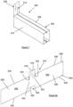
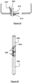
- FIG 1 is a perspective view of a support apparatus 100 configured as a hanger assembly 102.
- the hanger assembly 102 includes a hanger end plate assembly 200 mounted to an upper supporting structure 104 such as a ceiling or roof, and connected to a vertical stiffener 300 in order to suspend the vertical stiffener 300 from the supporting structure 104.
- the hanger system 102 further includes two horizontal stiffeners 400,402 with a respective end coupled to the vertical stiffener 300 via a corresponding load bearing connector 500,502. With such an arrangement, the hanger system 102 may be used where walling requires vertical and horizontal support above windows or other forms of opening which spans a distance.
- the hanger system 102 is configured to "hang" from the upper structure 104 with sufficient strength to carry weight of a wall constructed between the horizontal stiffeners 400,402 and the upper structure 104. Further, connections between the vertical stiffener 300 and the hanger end plate assembly 200, the vertical stiffener 300 and the two horizontal stiffeners 400,402, the wall to be constructed and the hanger system 102 should be sufficiently strong and secure to achieve cantilever action from the supporting structure 104 to resist horizontal loads (eg. wind pressure) applied to the wall to be constructed and top part of the window or other forms of opening. Components of the hanger system 102 will be described in detail next, including the various connections in order to appreciate how the hanger system 102 is able to address these aims.
- horizontal loads eg. wind pressure
- FIG 2 is an exploded perspective view of the hanger end plate assembly 200 of Figure 1 .
- the hanger end plate assembly 200 includes a hanger connector plate 202 having a substantially flat connector primary plate 204 with an outer planar surface 206 for contacting against the upper support structure 104, and an inner planar surface 208.
- the connector primary plate 204 further includes a first side leg portion 210 and a second side leg portion 212 integrally formed with the connector primary plate 204.
- the first and second side leg portions 210,212 extend linearly from a respective edge of the connector primary plate 204 so that both side leg portions 210,212 are adjacent to the inner planar surface 208, opposite of each other and spaced apart at a separation distance AA.
- the hanger connector plate 202 further includes end stoppers in the form of bent lugs 214,216 extending inwardly of the inner planar surface 208 and from a respective end of the connector primary plate 204.
- the hanger connector plate 202 also includes two primary plate attachment holes 218,220 spaced apart of each other, with each hole 218,220 positioned near to a respective bent lug 214,216.
- Each side leg portion 210,212 has an arrangement of engagement members 222 and in this embodiment, the arrangement of engagement members 222 of both side leg portions 210,212 are similar and thus, one of the side leg portion 212 will be used to elaborate on the engagement members 222.
- the arrangement of engagement members 222 is arranged as first column engagement perforations 224,228 and second column engagement perforations 230,234 with the engagement perforations 224,228 of one column being offset from the engagement perforations 230,234 of the other column.
- Each engagement perforation 224,228,230,234 is similar in structure and using a first one 224 of the first column engagement perforations, the engagement perforation 224 includes an elongate slot 224a and a centre opening 224b to form a generally T-shape engagement perforation 224.
- the second column engagement perforations 230,234 also has a similar structure, and looking at the first one 230, it also has an elongate slot 230a and a centre opening 230b. From Figure 2 , it can be appreciated that the centre openings 224b,230b of the first column engagement perforations 224,228 and the second column engagement perforations 230,234 are arranged to face inwardly, diagonally opposite of each other, and the elongate slots 224a of the first column engagement perforations 224,228 extend along a first linear axis BB and the elongate slots 230a of the second column engagement perforations 230,234 extend along a second linear axis CC.
- first column engagement perforations 224,228 are offset from the second column engagement perforations 230,234 to form corresponding pairs of engagement perforations with the engagement perforations within the same pair being offset from each other. More specifically, the first one of the first column engagement perforation 224 forms a first pair of engagement perforations 224,230 with the first one of the second column engagement perforation 230. Similarly, the second ones of the respective first and second column engagement perforations 228,234 form a second pair of engagement perforations 228,234.
- the amount of offset between the engagement perforations of each pair of engagement perforations is 50mm (taking the first pair 224,230 as an example, this is measured between the centre openings 224b,230b in a direction parallel to BB or CC).
- Each side leg portion 210,212 also includes a side leg portion retainer 236,238 integrally formed with the side leg portions 210,212.
- the side leg portion retainers 236,238 are formed on the side leg portion 210,212 at a distance and near to the connector primary plate 204 by cutting along three sides to form respective rectangular lugs 240,242 pivoted at one side and the rectangular lugs 240,242 are forced or bent inwardly to point towards the inner planar surface 208 to form the side leg portion retainers 236,238 which are also resiliently biased in view of the pivotal connection.
- the hanger end plate 200 also includes a number of support plates 244 of various thicknesses but they have similar widths and lengths. Indeed, the widths of the support plates 244 may vary slightly in order for the end profiles of the support plates 244 to follow the integral connection between the connector primary plate 204 and the first side and second side leg portions 210,212.
- the number of support plates 244 includes a main structural plate 246, a primary packer plate 248 and a secondary packer plate 250.
- Each of the support plates 246,248,250 has two support plate attachment holes 252,254 which are in registration with corresponding ones of each respective support plate 246,248,250, and also in registration with the respective primary plate attachment holes 218,220 when the support plates 246,248,250 are assembled to the hanger connector plate 202.
- the support plates 246,248,250 are inserted between the two opposing side leg portions 210,212 and pushed past the two side leg portion retainers 236,238 (which causes the side leg portion retainers 236,238 to flex outwardly to allow the support plates 246,248,250 through) and once the support plates 246,248,250 are clear of the side leg portion retainers 236,238, the side leg portion retainers 236,238 flexes or biases inwardly to retain the support plates 246,248,250 in position and against the inner planar surface 208, as shown in Figure 1 .
- the lengths of the support plates 246,248,250 are also adapted to match the lengths of the connector primary plate 204 and thus, the bent lugs 214,216 together with the side leg portion retainers 236,238 are used to retain the support plates 246,248,250 in place.
- Masonry anchors or similar fasteners are then inserted into the support plate attachment holes 252,254 and the primary plate attachment holes 218,220 in order to secure the hanger end plate assembly 200 to the upper support structure 104.
- Figure 3 is a partial cross sectional view in a direction D-D of the support apparatus 100 of Figure 1 to show the assembly of the hanger end plate assembly 200 more clearly.
- the hanger connector plate 202 may be formed from a single piece of metal sheet (for example of 2.5mm thickness), cut and the two side leg portions 210,212 bent in place with respect to the connector primary plate 204 (similarly, the side leg portion retainers 236,238 and the pairs of engagement perforations 224,230;228,234 are all integrally formed without any welding).
- Figure 3 shows a bend 256 between the connector primary plate 204 and one of the side leg portions 212. Radius of curvature of the bend 256 needs to be tightly controlled since if the bend 256 is excessively curved, this may cause a fracture and thus, reduce the strength of the hanger connector plate 202.
- geometries of the support plates 246,248,250 are controlled or adapted to ensure that the bend 256 are maintained at a suitably large radius so as not to compromise the strength of the hanger connector plate 202 during load applications.
- widths of the support plates 246,248,250 vary slightly so that when the support plates 246,248,250 are stacked, edges 246a,248a,250a of each support plate 246,248,250 engages respective parts of the bend 256 in order to control the radius of the curvature.
- the thickness of the support plates 246,248,250 also vary, with the main structural plate 246 thicker than the primary packer plate 248, and the primary packer plate 248 thicker than the secondary packer plate 250 in order to create gradual staggered steps created by the edges 246a,248a,250a of the support plates 246,248,250.
- the main structural plate 246 should be of sufficient thickness to transfer cantilever actions from the vertical stiffener 300 to the upper support structure 104.
- thickness of the main structural plate 246 may be about 16mm to 25mm, and it may vary depending on the size of the hanger end plate assembly 200.
- the highly stressed connection between the vertical stiffener 300 and the main structural plate 246 is achieved using components which are easily manufactured and assembled, and as a result, eliminates any welding for the support apparatus 100. Indeed, as welding is eliminated, pre-galvanised steel may be used for all the components of the support apparatus 100 and no subsequent surface treatment may be necessary (which would otherwise be needed to reduce corrosion of the steel because welding damages the galvanized coating).
- the support apparatus is suitable for standardized components to be held in stock and assembled at short notice to suit typical orders. This is hard to achieve if welding is used since that would mean that the length of the vertical stiffener 300 needs to be known before fabrication may economically proceed.
- the hanger end plate 200 allows the vertical stiffener 300 to cantilever down from the upper structure 104 and thus, the vertical stiffener 300 is connected to the hanger end plate assembly 200.
- the vertical stiffener 300 has four side walls to form a substantially rectangular hollow box section and two side walls 302,304 are shown in Figure 1 (with the other two side walls only partly shown at the bottom of the vertical stiffener 300). It should be apparent that the structure of each of the four side walls is similar to each other and thus, only a first side wall 302 will be elaborated.
- FIG 4 is an enlarged view of portion EE of the support apparatus 100 of Figure 1 to show a portion of the first side wall 302 of the vertical stiffener 300 more clearly.
- the first side wall 302 includes a plurality of side wall engagement members 306 disposed at discrete positions along the first side wall 302, and in this embodiment, the side wall engagement members 306 are in the form of side wall engagement perforations 308 arranged along two substantially parallel axes FF and GG and for ease of reference, the engagements perforations 308 along the first axis FF, would be termed first axis engagement perforations 310,312 and the engagement perforations 308 along the second axis GG would be termed second axis engagement perforations 314,316,318. It should be apparent from Figure 4 that the first axis engagement perforations 310,312 are offset from the second axis engagement perforations 314,316,318.
- the first perforation 310 includes an elongate slot 310a extending along and aligned to the first axis FF, and a number of recesses projecting from the elongate slot 310a.
- the first perforation 310 includes a main recess 310b disposed around the centre of the elongate slot 310a and projecting outwardly of the first side wall 302 of the vertical stiffener 300 along a first direction substantially perpendicular to the first axis FF.
- the first perforation 310 further includes three secondary recesses 310c,310d,310e spaced apart at about 25mm from each other and projecting inwardly of the first side wall 302, in a second direction which is opposite of the first direction, from the elongate slot 310a.
- a first secondary recess 310c is located near one end of the slot 310a
- a second secondary recess 310d is disposed near the centre of the slot 310a directly opposite of the main recess 310b
- a third secondary recess 310e is disposed at the other end of the slot 310a.
- each of the first axis engagement perforations 310,312 have a similar configuration and orientation as the first perforation 310 described above, and whereas the second axis engagement perforations 314,316,318 also have a similar structure as the first perforation 310 but in a different orientation.
- the middle perforation 316 has an elongate slot 316a, a main recess 316b and three secondary recesses 316c,316d,316e arranged in a similar structure but orientation of the main recess 316b and the three secondary recesses 316c,316d,316e are different.
- the main recess 316b is orientated to face the second direction (i.e.
- the third secondary recess 310e of the first perforation 310 is in line with the first secondary recess 316c of the middle perforation 316.
- the vertical stiffener 300 may then be mounted to the hanger end plate 200 using connector such as pin connector assemblies 600 shown in Figure 1 .
- An enlarged unassembled view of the pin connector assembly 600 is shown in Figure 5 .
- the pin connector assembly 600 includes a double pin connector 602 and a double pin connector bracket 604.
- the double pin connector 602 includes an elongate pin body 606 and two upstanding or projecting abutment pins 608,610 at each end of the pin body 606 with a respective slightly tapered abutment surface 612,614 at the end of the respective abutment pin 608,610.
- Figures 6a, 6b and 6c illustrate the forming of the double pin connector 602 using progressive punching.
- Figure 6a illustrates a preformed pin connector structure 616 cut from a sheet of metal, such as steel, of a desired thickness.
- the preformed pin connector structure 616 includes two elongate arms 618,620 with free ends 622,624 facing in opposite directions and connected to an elongate body 626 to form a generally N-shape structure.
- the preformed pin connector structure 616 also includes a V-shaped notch 628,630 formed at a predetermined location along the respective elongate arms 618,620 with opening of the V-shape notch 628,630 facing outwards.
- the preformed pin connector structure 616 is next bent at the V-shape notch 628,630 of the elongate arms 618,620 by folding the respective free end 612,614 inwardly to form respective folded elongate arms 632,634, which also forms the respective tapered abutment surface 612,614, as shown in Figure 6b .
- the folded elongate arms 632,634 are bent adjacent to the respective free ends 622,624 to create the upstanding abutment pins 608,610 which are substantially perpendicular relative to the elongate body 626 which forms the elongate pin body 606, as shown in Figure 6c . In this way, the double pin connector 602 is formed.
- the double pin connector bracket 604 may be formed in a similar manner as the double pin connector 602 using progressive punching, and thus, no further elaboration is needed.
- the double pin connector bracket 604 is formed from a single sheet of metal and bent at designated locations to form a generally C-shape bracket body 636 having a substantially planar main bracket body 638 with two bracket legs 640,642 extending from the main bracket body 638 substantially perpendicular. It should be appreciated that one of the bracket legs 640 is offset from the other bracket 642 in a similar way as the first axis engagement slots 310,312 and second axis engagement slots 314,316,318. Each bracket leg 640,642 includes a protruding engagement element and in this embodiment, the protruding engagement element is in form of a raised ridged strip 644,646 which creates a kink 648,650.
- both ridged strips 644,646 of the bracket legs 640,642 face each other.
- the double pin bracket 604 also includes two pin openings 652,654 (although one of the pin openings 654 cannot be seen from Figure 5 ) formed on the main bracket body 638 adjacent the respective bracket legs 640,642 and where the bracket legs 640,642 meet the main bracket body 638.
- the raised ridged strips 644,646 are arranged to occlude or at least partially block the respective two pin openings 652,654.
- the pin openings 652,654 are adapted to match the abutment pins' profile and thus, the pin openings 652,654 are square or rectangular. It should be apparent that the ridged strips 644,646 are suited for progressive punching but the protruding element may adopt other geometries, especially if other manufacturing process is used.
- the pin connector assembly 600 has various uses and is used to attach the vertical stiffener 300 to the hanger end plate 200 in a similar way as the load bearing connectors 500,502 (and thus, the horizontal stiffeners 400,402) are attached to the vertical stiffener 300. Thus, an explanation of how the attachment or connection is carried out will be discussed later.
- FIG 7 is a perspective view of one of the load bearing connectors 500 including a sleeve member 504 integrally formed with a connecting plate 506 as a unitary structure.
- the sleeve member 504 is formed by two opposing arm members 508,510 arranged to be insertable into the horizontal stiffener 400 for transferring loads applied to the horizontal stiffener 400 to the sleeve member 504 and hence to the connecting plate 506.
- the connecting plate 506 is connectable to the vertical stiffener 300 for transferring the load from the sleeve member 504 to the vertical stiffener 300.
- the connecting plate 506 includes connecting plate engagement members 512 which are similar to the engagement members 222 of Figure 2 (i.e. engagement slots) and thus, no further elaboration will be needed.
- Figures 8a , 8b and 8c illustrate the forming of the load bearing connector 500, also by progressive punching.
- Figure 8a illustrates a preformed load bearing structure 514 cut as part of the progressive punching process from a sheet of metal such as steel, of a desired thickness.
- the preformed load bearing structure 514 includes a centre plate 516 (with the connecting plate engagement members 512 already formed), substantially rectangular with a first end 518, a second end 520, and sides 522,524.
- the preformed load bearing structure 514 includes two wing plates 526,528 extending longitudinally from the respective sides 522,524 of the centre plate 516.
- the preformed load bearing structure 514 also includes two parting line gaps 532,534 along the sides 522,524 which stop at a certain dimension and do not extend along the entire sides 522,524 of the centre plate 516 to enable the wing plates 526,528 to be integrally joined to the centre plate 516.
- edges 536,538,540,542 of the wing plates 526,528 are folded inwardly at roughly right angles to wing plate bodies 544,546 of the wing plates 526,528 along first folding lines 548,550 shown in Figure 8a and adjacent the respective edges 536,538,540,542, to form lips 552,554,556,558 along the longitudinal axis of the wing plates 544,546 as shown in Figure 8b .
- the wing members 526,528 are further folded inwardly and along second folding lines 560,562 which correspond to the depth of the parting line gaps 532,534 and second end 520 of the centre plate 516 respectively to form a pair of lipped channels 564,566, as shown in Figure 8c .
- the pair of lipped channels 564,566 are brought towards each other by bending the wing plates 526,528 along the sides 522,524 of the centre plate 516 to bring the lips 556,558 into contact with respective opposing lips 552,554 and which effectively forms a box-shaped structure which forms the sleeve member 504 (and the pair of lipped channels 564,566 thus forms the two opposing arm members 508,510) shown in Figure 7 .
- the sleeve member 504 is inserted into the horizontal stiffener 400 in order to attach the horizontal stiffener to the vertical stiffener and which makes the effective length of the horizontal stiffener adjustable (telescopically).
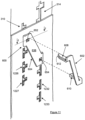
- This is carried out by attaching the connecting plate 506 to vertical stiffener 300 using two pin connector assemblies 600 as shown in Figure 9 , which is a closed up view of the connection between the horizontal stiffener 400 and the vertical stiffener 300 of Figure 1 at the second side wall 304.
- Figure 10 is an enlarged view of portion HH of Figure 9 , but before coupling of the two pin connector assemblies 600.
- Figure 4 shows a part of the first side wall of the vertical stiffener but since the second side wall 304 has also the same structure, the same references will be used.
- the connecting plate 506 includes the engagement members 512 which are similar in structure (four engagement perforations in two columns- with engagement perforations 1224,1225,1226,1227 in one column, and the other column showing four engagement perforations 1230,1231,1232,1233) as the engagement members 222 of the hanger connector plate 202 (refer to figure 2 ), and thus, the similar references will be used with an addition of 1000.
- a user holds the load bearing connector 500 against the second side wall 304 of the vertical stiffener 300 and registers the first one 1224 of the first column engagement perforations with one of the first axis engagement perforations 310,312 and similarly the first one 1230 of the second column engagement perforations with one of the second axis engagement perforations 314,316,318 of the second side wall of the vertical connector.
- the user registers the centre opening 1224b of the first one 1224 of the first column engagement perforations with the second secondary recess 310d (not shown in Figure 10 ) of the first perforation of the first axis engagement perforation 310 and similarly, the elongate slot 1224a is registered or aligned with the elongate slot 310a of the first perforation 310.
- the user aligns the centre opening 1230b of the first one 1230 of the second column engagement perforations with the second secondary recess 316d of the middle perforation 316 of the second axis engagement perforations and likewise, the elongate slot 1230a is also aligned with the elongate slot 316a of the middle perforation 316.
- the registration and alignment of the various perforations, recesses and openings thus creates respective aligned perforations.
- the pin connector assembly 600 is used to couple the connecting plate 506 (and thus, the load bearing connector 500) to the vertical stiffener 300.
- the bracket leg 640 is adapted to slide or insert into the elongate slot 1224a and elongate slot 310a which are in registration with each other, and the ridged strip 644 is inserted through the centre opening 1224b and the second secondary recess 310d.
- the other bracket leg 642 is also inserted into the elongate slot 1230a and the elongate slot 316a with the ridged strip 646 inserted through the centre opening 1230b and the second secondary recess 316d of the middle perforation 316.
- the pin connector assembly 600 is insertable selectively into any of the corresponding secondary recesses 310c/316c, 310e/316e and not just the second secondary recesses 310d,316d.
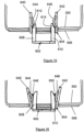
- Figures 13 and 14 are sectional plan views in a direction J-J of Figure 11 , showing before insertion of the double pin bracket 604, and after inserting the double pin bracket 604 into the slots and recesses of the connecting plate 506 and the vertical stiffener 300 i.e.
- Figure 13 corresponds with Figure 10
- Figure 14 corresponds with Figure 11 .
- the double pin connector 602 of the connector pin assembly 600 is next positioned with the one of the abutment pins 608 aligned with one of the pin openings 652, and the other abutment pin 610 aligned with the other pin opening 654 of the double pin bracket 604.
- the abutment pins 608,610 of the double pin connector are forced into the respective pin openings 652,654 using a mallet or similar instrument capable of applying impact.
- Figure 15 is a sectional plan view similar to Figure 13 but corresponds to the partial insertion of the abutment pins 608,610 into the pin openings 652,654.
- the ridged strips 644,646 provides resistance, forcing the bracket legs 640,642 and the abutment pins 608,610 to distort slightly, forming a wedge connection between the ridged strips 644,646 and the abutment pins 608,610.
- Figure 12 illustrates a proper connection between the double pin bracket 604 and the double pin connector 602 and this is also illustrated in Figure 16 , which is a sectional plan view similar to Figure 15 but Figure 16 corresponds to Figure 12 .
- the wedge connection includes the kinks 648,650 engaging the respective abutment pins 608,610 and comparing Figure 16 with Figure 15 , it should be appreciated that the bracket legs 640,642 are forced slightly outwards, whereas the abutment pins 608,610 are slightly forced inwards to form the wedge connection.
- the distorted bracket legs 640,642 in cooperation with the abutment pins 608,610 forms a locking mechanism to fasten the connecting plate 506 (and thus, the load bearing connector 500) and the vertical stiffener 300 together.
- the wedge connection increases the contact between the double pin connector 602, the double pin bracket 604 and the engagement members 310,316, enabling loads in any direction to be transferred between the mating horizontal stiffener 400, the load bearing connector 500 and the vertical stiffener 300.
- Figure 9 illustrates that another connector pin assembly 600 is used to connect the loading bearing connector 500 to the vertical stiffener 300, and the same procedure as explained above applies. Since it is preferred to have two connector pin assemblies 600 (i.e. a pair) for a more effective connection and load transfer, providing the two columns of four engagement perforations each 1224,1225,1226,1227/1230,1231,1232,1233 allows adequate spacing between the two connector pin assemblies 600.
- the pair of connector pin assemblies 600 are spaced apart by two first column and second column perforations of the connecting plate 506, as shown in Figure 9 .
- connection of the load bearing connector 500 to the vertical stiffener 300 using the connector pin assemblies 600 is offset from the centre of the horizontal stiffener 400.
- any horizontal loads would tend to make the connection "twist" due to the offset so that the pair of connector pin assemblies 600 reduces or prevents such twisting action.
- the hanger end plate 200 is connected securely to the vertical stiffener as shown in Figure 1 .
- the double pin assemblies are inserted into the side wall engagement members 306 and the engagement members 222 of the first side leg portion 210 (and into the second side leg portion 212) to achieve a secured connection and at the same time, maximizes the contact between all the mating components for effective load transfer.
- the load bearing connector 500 illustrated in Figure 7 is integrally formed from a single sheet of metal, no welding is necessary. Indeed, the load bearing connector 500 may be manufactured using a fully automated progressive punching process, which involves punching and folding of a sheet or roll of steel plate to form the final part, as described earlier. Also, the sleeve member 504 is able to slide within the horizontal stiffener 400 and thus, provides for horizontal tolerance. In terms of the vertical tolerance, separation distance between engagement perforations 1224,1225,1226,1227 (or 1230,1231,1232,1233) is 25mm i.e. the engagement perforations are disposed at discrete positions by 25mm increments.
- the hanger assembly 102 may be used to support a wall above a window for example.
- the wall may be made of masonry and thus, the masonry needs to be tied to the vertical stiffener 300 to achieve the support.
- a T-tie member 700 is proposed and this is shown in Figure 17 .
- the T-tie member 700 comprises a relatively flat tie body 702 and opposing plate extensions 704,706 to form a general T-shape relative to the tie body 702. Specifically, it may be regarded that the tie body 702 extends horizontally along a longitudinal axis, and the opposing plate extensions 704,706 extend vertically relative to the longitudinal axis. Further, the T-tie member 700 includes three projecting lugs 708,710,712 which are created by bending legs which extend out at predetermined positions of the opposing plate extensions 704,706 at specific angles and dimensions.
- the first and third projecting lugs 708,712 are disposed at ends of and substantially perpendicular to the opposing plate extensions 704,706 and extend in a direction opposite to the second projecting lug 710, which is disposed nearly or substantially equally between the first and third projecting lugs 708,712 and near the tie body 702. In this way, any load applied to the tie body 702 is distributed nearly equally or relatively evenly spread to each of the three lugs 708,710,712.
- the T-tie member 700 further includes two elongate troughs 714,716 spaced apart and parallel to each other which create opposing raised ridges on the underside of the tie body 702.
- the elongate troughs 714,716 may increase stiffness and improve load transfer to cement work between bricks or construction blocks.
- Each plate extension 704,706 also includes a plate extension trough 718,720 with a corresponding ridge portion 722,724, which is similar to the elongate troughs 714,716 on the tie body 702.
- the ridge portions 722,724 of the plate extensions 704,706 extend in opposite directions with the ridge portion 722 of the first plate extension 704 pointing away from the tie body 702, whereas the ridge portion 724 of the second plate extension 706 points towards the tie body 702. It should also be appreciated that the elongate troughs 714,716 are roughly aligned with the plate extension troughs 718,720 along respective longitudinal axes.
- the tie body 702 is inserted between the wall material such as cement of the masonry wall (with the elongate troughs 714,716 embedded in the cement), and the projecting lugs 708,710,712 are engaged with side wall engagement members of the vertical stiffener 300.
- the T-tie member 700 would be engaged with the second side wall 304 as the wall would be constructed above the horizontal stiffener 400.
- the T-tie member 700 is constructed to match the profile of the engagement perforations 308 (along axes FF,GG) and as an example, the first and third projecting lugs 708,712 are arranged to be inserted into and engaged with main recesses 314b and 316b of two of the second axis engagement perforations 314,316 respectively, with the second projecting lug 710 arranged to be inserted into and engaged with the main recess 310b of the first one 310 of the first axis engagement perforations. It should be appreciated that the T-tie member is thus engaged within the elongate slots 310a, 314a, 316a.
- T-tie member 700 Vertical movement of the T-tie member 700 along the elongate slots 310a,314a,316a allows it to be aligned with bedding joints of the wall material. It should be appreciated that the T-tie member 700 may be rotated 180 degrees (referring to Figure 17 , the elongate troughs 714,716 would face below) with the first and third projecting lugs 708,712 now arranged to engage with the main recesses 310b,312b of the first axis engagement perforations 310,312, whereas the second projecting lug 710 would be arranged to engage the main recess 316b of the middle perforation 316 of the second axis engagement perforations. In this way, a full range of positions along the entire length of the vertical stiffener 300 may be achieved.
- the T-tie member 700 is arranged to transfer horizontal loads from the wall material to the support apparatus 100, and in this embodiment, this would be the vertical stiffener 300.
- the horizontal tie body 702 is located such that the applied load is distributed nearly equally to each of the projecting lugs 708,710,712 and as a result, the T-tie member 700 is able to withstand suitable load capacities even though the tie body 702 may only have a thickness of around 0.8mm, much lower than other tie members.
- the T-tie member 700 is also suitable for manufacturing using the progressive punching process, and the T-tie member 700 is preferably integrally formed.
- the double pin assembly 600 may be used in combination with a pair of binder connectors 800,850 to bind two stiffeners 360,370 together and one of the binder connectors 800 is shown in Figure 18 .
- the binder connector 800 has a generally S-shape cross-section binder body 802 and made of a thin strip of steel plate bent at specific locations to form the S-shape to define a first connecting portion 804 and a second connecting portion 806 which are opposite to each other and having a common linkage.
- the binder body 802 includes a first binder section 808 coupled to a second binder section 810 with the second binder section forming a right angle with the first binder section 808, and the second binder section 810 extends into a third binder section 812 which is also perpendicular to the second binder section 810 (and in the same general direction as the first binder section) to form the first connecting portion which is generally C-shape.
- the third binder section 812 further extends to a fourth binder section 814 in a direction substantially parallel to the second binder section 810 and the fourth binder section 814 further extends to a fifth binder section 816 to form the second connecting portion 806 and it should be appreciated that the third binder section 812 forms the common linkage with the first connecting portion 804.
- the first connecting portion 804 defines a first connecting portion receiving space 818 for receiving about half of the profile of the stiffener
- the second connecting portion 806 (directly adjacent to the first connecting portion 804) defines a second connecting portion receiving space 820 for receiving also about half of the second of the stiffeners but in opposite relationships to each other.
- the binder connector 800 further includes a first binder engagement member 822 disposed at the first binder section 808 and a second binder engagement member 824 disposed at the fifth binder section 816.
- the first binder engagement member 822 and the second binder engagement member 824 are in the form of binder engagement slots which have a similar structure as the first column engagement slots 224,228 or the second column engagement slots 230,234 of the hanger connector plate 202 shown in Figure 2 .
- the second binder connector 850 of the pair needs to be rotated in an opposite orientation to the first binder connector 800 as shown in Figure 19 .
- the same references will be used for the second binder connector for like parts with the addition of 50.
- the first binder section 858 of the second binder connector 850 would be adjacent to the fifth binder section 816 of the first binder connector 800, and the fifth binder section 866 of the second binder connector 850 would be directly adjacent to the first binder section 808 of the first binder connector 800.
- first binder engagement member 872 of the second binder connector 850 is offset to the second binder engagement member 824 of the first binder connector 800 just like the first column engagement slots 224,228 and the second column engagement slots 230,234 of the hanger connector plate 202.
- second binder engagement member 874 of the second binder connector 850 is offset in a similar manner to the first binder engagement member 822 of the first binder connector 800.
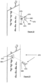
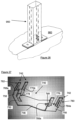
- FIG 20 illustrates the use of the first binder connector 800 and the second binder connector 850 to bind the two substantially identical stiffeners 360,370 which are similar to the vertical stiffener 300 of Figure 1 .
- each of the two stiffeners 360,370 has four side walls - first side wall 362,372, second side wall 364,374, third side wall 366,376 which are directly opposite of the first side wall 362,372 and fourth side wall 368,378 directly opposite of the second side wall 364,374.
- the side walls of the stiffeners 360,370 also includes the engagement slots 306 illustrated in Figure 4 , but these are not shown in Figure 20 for simplicity.
- the first binder section 808 of the first binder connector 800 is first placed on the first side wall 362 of the first stiffener 360 and the second binder section 810 then extends across the face of the second side wall 364 and the third binder section 812 extends across and is sandwiched between the third side wall 366 of the first stiffener 360 and the first side wall 372 of the second stiffener 370, and the first binder connector 800 next snakes around the second stiffener 370 with the fourth binder section 814 extending across the fourth side wall 378 of the second stiffener, and finally the fifth binder section 816 ends on the third side wall 376 of the second stiffener 370.
- the second binder connector 850 (of similar profile as the first binder connector 800) goes in the opposite orientation with the first binder section 858 placed on the third side wall 376 of the second stiffener 370, and the second binder section 860 of the second binder connector 850 extending across the second side wall 374 of the second stiffener 370, and the third binder section 862 of the second binder connector 850 is similarly sandwiched between the first side wall 372 of the second stiffener 370 and the third side wall 366 of the first stiffener 360.
- the second binder connector 850 further extends around the first stiffener 360 with the fourth binder section 864 of the second binder connector 850 extending across the face of the fourth side wall 368 of the first stiffener 360 and finally the fifth binder section 866 ends on the first side wall 362 of the first stiffener offset with the first binder section 808 of the first binder connector 800.
- the first connecting portion 804 of the first binder connector 800 cooperates with the second connecting portion 856 of the second binder connector 850 and the second connecting portion 806 cooperates with the first connecting portion 854 of the second binder connector to envelope all the side walls of the first and second stiffeners 360,370 and to connect the first and second stiffeners 360,370 in a side-to-side arrangement.
- Two pin connector assemblies 600 are next installed to engage the first binder engagement member 872 of the second binder connector 850 and the second binder engagement member 824 of the first binder connector 800, and also the second binder engagement member 874 of the second binder connector 850 and the first binder engagement member 822 of the first binder connector 800 to secure both stiffeners 360,370 together, and similarly secures the first binder connector 800 and the second binder connector 850 to the stiffeners 360,370.
- the profile and the opposing orientation of the first and the second binder connectors 800,850 ensures that the two stiffeners 360,370 move together perpendicular to the plane of the wall to be constructed and the two binder connectors 800,850 also tie the two stiffeners 360,370 together for transport or installation purposes. Needless to say, the binding of the two stiffeners 360,370 may also be performed on site. Locating the connector pin assemblies 600 on the stiffeners' 360,370 external side walls 362,376 allows for easy access to secure the two binder connectors 800,850 and avoids significant protrusions on the second and fourth side walls 364,368,374,378 where fire rating may be compromised or finishing could be affected.
- the binder connectors 800,850 are easy to manufacture and a robust connection with the two stiffeners 360,370 may be achieved without a need for welding or complex installation procedures.
- the binder connectors 800,850 may include further binder sections beyond the fifth binder section 816,866 in the event that more than two stiffeners 360,370 need to be bound or connected together.
- Figure 21 illustrates a number of pairs of binder connectors 800,850 are used to connect the two stiffeners 360,370 together of substantial height at designated or discrete locations along the length of the stiffeners 360,370. Indeed, such a configuration of two (or more) stiffeners 360,370 being bound together may be used as part of the support apparatus 100, for example, when reinforcing a particular structure.
- the pin connector assembly 600 may come in other forms and may not be in the form of the double pin connector 602.
- the pin connector assembly 600 may include a single pin connector 670 comprising a single projecting abutment pin 672 (see Figure 23 ) and a single pin bracket 674 (which broadly are half of what is illustrated in Figure 5 ).
- the single pin bracket 674 includes an L-shape bracket body 676 having a single pin bracket leg 678 extending from a single pin bracket body 680.
- the single pin bracket 674 includes a single pin ridged strip 682 and a single pin opening 684 just like the structure of one side of the double pin bracket 604, with the single pin ridged strip 682 also occluding or at least partially blocking the single pin opening 684.
- Figure 23 illustrates the single pin connector 670 having the single projecting abutment point 672 and a single pin tapered surface 686 about to be driven into the single pin opening 684 of the single pin bracket 674.
- Figure 24 illustrates how the single abutment pin 672 is wedged together with the single pin ridged strip 682 and it should be appreciated that the bracket leg 678 and the single abutment pin 672 are slightly distorted or forced apart just like what has been described for the double pin connector 602.
- the double pin connector 604 may also be substituted with two single pin connectors 670, although this is not preferred as the double pin connector 604 ensures that the user engages both points along the vertical stiffener which makes the connection more secure. It is also envisaged that the double pin connector 604 may make use of two single pin projecting pins 672 (instead of the double pin connector 602) or the double pin connector 602 may be used with two single pin brackets 674.
- the pin connector assemblies 600 may also be used to connect two (or more) stiffeners 900,902 together with an end-to-end arrangement, such as that shown in Figure 25 with an inner sleeve 904.
- the support apparatus 100 also has other uses, for example, configured as a post assembly 950 having similar components as the hanger assembly 102 but inverted (although the horizontal stiffeners are not shown) and the post assembly 950 is mounted to a floor or lower structure 960 instead of the ceiling or upper support structure.
- the support apparatus 100 may also come in various configurations.
- the hanger connector plate 202 of the hanger end plate assembly 200 is substantially perpendicular with respect to the first and second side leg portions 210,212, but this may not be necessarily so.
- the hanger connector plate 202 may be formed at an oblique angle with respect to the first and second leg portions 210,212 which may be useful for mounting the hanger connector plate 202 to a sloping ceiling (or floor).
- the support plates 246,248,250 may or may not be used, and if the support plates 246,248,250 are used, they may be configured (size, thickness etc) accordingly.
- the connector is, according to the present invention, in the form of a connector bracket 740 with a self-locking mechanism 742 and Figure 27 illustrates the connector bracket 740 from a front view and Figure 28 illustrates the connector bracket 740 from a back view.
- the connector bracket 740 is formed from a single sheet of metal and Figures 29a to 29e illustrate the forming of the connector bracket 740 by progressive punching, similar to the pin connector 602.
- Figure 29a illustrates a preformed bracket structure 744 made by progressive punching from a sheet of metal, such as steel, of a desired thickness.
- the preformed bracket structure 744 includes a base member 746 having first and second bracket openings 748,750 formed by progressive punching and positioned below respective arm sections 752,754 which extend from opposite ends of the base member 746 and in opposite directions.
- Each of the arm sections 752,754 has a neck portion 756,758 which is common to and joins a finger member 760,762 and two side arms 764,766,768,770 with the finger member 760,762 arranged between respective side arms 764,766,768,770.
- Each of the side arms include slits to create separable side arm members 764a,766a,768a,770a.
- the finger members 760,762 extend longer than the side arms 764,766,768,770 and as a first step, ends 760a,762a of the finger members are folded outwards onto itself at a predetermined distance from the ends 760a,762a to form a respective first fold 772,774 as shown in Figure 29b .
- the finger members 760,762 are folded inward near a line adjoining the neck portion 756,758 so that the first fold 772,774 extends into the respective openings 748,750 of the preformed bracket structure 744, as shown in Figure 29c .
- the neck portions 756,758 are folded further inwardly so that the neck portions 756,758 are substantially perpendicular to the plane of the base member 746 as shown in Figure 29d , and the neck portions 756,758 and respective side arms 764,766,768,770 form corresponding connector bracket legs 780,782 of the connector bracket 740.
- the first folds 772,774 of the finger members 760,762 are located within the corresponding openings 748,750.
- the openings 748,750 are sized to accommodate or receive the width of the respective finger members 760,762.
- the series of folded finger members 760,762 form corresponding protruding engagement elements 776,778 which occlude or at least partially block the respective openings 748,750.
- the separable side arm members 764a,766a,768a,770a are flexed apart at the slits as shown in Figure 29e so that the respective side arms 764,766,768,770 create a wider profile near the neck portions 756,758 than at the pivoted end.
- the side arm members 764a,766a,768a,770a are thus compressible inwards (due to the slits) which enables the side arms members 764a,766a,768a,770a to spring outwardly and these biased side arm members 764a,766a,768a,770a function as stoppers which form the self-locking mechanism 742.
- the connector bracket 740 is shown to couple the connecting plate 506 to the vertical stiffener 300. Similar to the pin connector assembly 600 (and specifically the pin connector bracket 604), the first of the connector bracket legs 782 is inserted through the elongate slot 1224a and elongate slot 310a which are in registration or aligned with each other, and the protruding engagement element 778 is inserted into the centre opening 1224b and the second secondary recess 310d.
- the dimensions of the connector bracket legs 782 and the protruding engagement element 778 are sized to fit snugly into the elongate slot 1224a and elongate slot 310a, and the centre opening 1224b respectively, so that there is minimum movement.
- the other connector bracket leg 780 is inserted into the elongate slot 1230a and the elongate slot 316a with the other protruding engagement element 776 inserted into the centre opening 1230b and the second secondary recess 316d of the middle perforation 316.
- the height "H” of the neck portions 756,758 (only one is illustrated in Figure 30 ) up till the slit of the separable side arm members 764a,766a,768a,770a are sized or configured to suit the combined thickness "T" of the connecting plate 506 and the vertical stiffener 300.
- the combined thickness "T” may range between 4.5mm and 6mm and the height "H" of the neck portion may be configured as 6.5mm and thus, the tolerance for a good fit may be between 2mm and as small as 0.5mm.
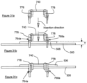
- Figures 31a to 31c are simplified cross-sectional views of Figure 30 from the top illustrating various stages of coupling the connector bracket 740 to the stiffener 300 and the connecting plate 506 and shows the thickness T (see Figure 31b).
- Figures 31a to 31c only shows two of the side arm members 764a and 768a for simplicity, although it should be appreciated that the other side arm members 766a,770a operate in the same manner.
- the bracket legs 780,782 are inserted into the perforations of the connecting plate 506 and the vertical stiffener 300 (see Figures 31a and 31b )
- the size of aligned elongate slot 1224a and elongate slot 310a compresses the side arm members 764a,768a.
- the separable side arm members 764a,768a clear the thickness T
- the slightly compressed side arm members 764a,768a bias outwardly and catch onto inner surface of the vertical stiffener 300, as shown in Figure 31c .
- the side arm members 764a,766a,768a,770a function like a compressible or one-way catch to allow the connector bracket 740 to lock or secure itself to the connecting plate 506 and the vertical stiffener 300 and at the same time, couples them together.
- the connector bracket 740 is particularly advantageous since there is no need of an additional connector pin, unlike the pin connector assembly 600, and as a result, there are cost savings.
- the self-locking mechanism 742 in the form of the compressible side arm members 764a,766a,768a,770a are easy to operate and secure, since once the side arm members 764a,766a,768a,770a locks in place, it is not possible to access them (since they would be on the inside of the stiffener 300).
- Both the connector bracket 740 and the pin connector assembly 600 enables locking from one direction since it is not possible to access these components from within the stiffener 300.
- the side arm members 764a,766a,768a,770a may be flexed outward in a different direction than that shown in Figures 31a to 31c .
- neck portions 756,758 which join the respective side arms 764,766, 768,770 and are configured to match the dimension of the respective perforations (i.e. the elongate slot 1224a and elongate slot 310a; and elongate slot 1230a and the elongate slot 316a), and together with respective protruding engagement elements 776,778 being engaged in the respective openings (i.e. centre opening 1224b and the second secondary recess 310d; and centre opening 1230b and the second secondary recess 316d), this allows the connector bracket 740 to withstand loads of 600 kg to 750 kg for typical steel grades and thicknesses likely to be employed.
- connector bracket 740 may be configured with one bracket leg (780 or 782) instead of two, depending on applications, similar to what is illustrated in Figures 22 to 24 .
- the connector bracket 740 is preferably integrally formed from a single sheet of metal using progressive punching or other known metal forming process, and indeed, just like the rest of the components of the support apparatus, without any welding. However, with advancement in 3D printing technology, it is envisaged that the components of the described embodiment may be 3D printed too.
- the components of the described embodiments have wide applications.
- the support apparatus 100, the hanger end plate assembly 200, the pin connector assembly 600 and the connector bracket 740 etc may be used to support walls or other structures without any walls.
- some or all of these components may be used for constructing sheltered pedestrian walkways, signage post support structures, building structures, highway sound barriers, racking support structures, partition support structures and railings balustrades and fences etc.
- the pin connector assembly 600 and the connector bracket 740 with its self-locking mechanism may be used to replace conventional means of fastening (bolts and welds) etc. The application is enormous.
Description
- The invention relates to a connector for coupling two or more components together.
- Support member systems for supporting walls are known, for example in
WO03/102321 -
FR 2518192 A1 US2009/044469 describes a device for fastening skirting. - Thus, it is desirable to provide a support apparatus which addresses at least one of the disadvantages of the prior art and/or to provide the public with a useful choice.
- In this invention, there is provided a connector operable to couple two or more components together according to claim 1, and a method of coupling two or more components together according to claim 6.
- Further aspects and preferred embodiments are set out in claim 2 et seq.
- Exemplary embodiments will now be described with reference to the accompanying drawings, wherein
figures 1-26 relate to embodiments not claimed in the present invention, andfigures 27-31c relate to the present invention, and in which: -
Figure 1 is a perspective view of a support apparatus; -
Figure 2 is an exploded perspective view of a hanger end plate assembly used in the support apparatus ofFigure 1 ; -
Figure 3 is partial cross sectional view in the direction D-D of the support apparatus ofFigure 1 ; -
Figure 4 is an enlarged view of portion EE of the support apparatus ofFigure 1 ; -
Figure 5 is an enlarged unassembled view of a connector in the form of a pin connector assembly comprising a double pin bracket and a double pin connector used inFigure 1 for coupling various components of the support apparatus securely together; -
Figures 6a to 6c illustrate how the double pin connector is formed; -
Figure 7 is a perspective view of a load bearing connector used in the support apparatus ofFigure 1 ; -
Figures 8a to 8c illustrate how the load bearing connector is formed; -
Figure 9 is a closed-up view of the connection between a horizontal stiffener, the load bearing connector ofFigure 7 and a vertical stiffener of the support apparatus ofFigure 1 ; -
Figure 10 is an enlarged view of a portion HH ofFigure 9 , prior to the connection and showing the double pin bracket ofFigure 5 ; -
Figure 11 shows the double pin bracket ofFigure 10 being inserted into the load bearing connector and the vertical stiffener ofFigure 10 , and showing the double pin connector ofFigure 5 ; -
Figure 12 shows the double pin connector and the double pin bracket of -
Figure 11 being assembled and arranged to attach the loading bearing connector and the vertical stiffener together; -
Figure 13 is a sectional plan view in a direction J-J ofFigure 11 , and which corresponds toFigure 10 ; -
Figure 14 is a similar view ofFigure 13 but corresponds toFigure 11 ; -
Figure 15 is a similar view ofFigure 13 but shows double pin connector partially inserted into the double pin bracket; -
Figure 16 is a similar view ofFigure 13 but shows the double pin connector fully inserted into the double pin bracket, which corresponds toFigure 12 ; -
Figure 17 is a perspective view of the T-tie used in the support apparatus ofFigure 1 to tie the support apparatus to a masonry wall; -
Figure 18 illustrates a binder connector which may be used together with the double pin connector ofFigure 5 ; -
Figure 19 illustrates two of the binder connectors ofFigure 18 which are placed in an opposing orientation in order to bind two stiffeners together; -
Figure 20 illustrates how the two binder connectors ofFigure 19 are used to bind two stiffeners together; -
Figure 21 illustrates the use of a plurality of pairs of binder connectors of -
Figure 19 to bind two stiffeners of substantial length or height together; -
Figures 22 and 23 illustrate an exemplary variation of the pin connector assembly ofFigure 5 comprising a single pin connector and a single pin bracket; -
Figure 24 shows how the single pin connector and the single pin bracket form a wedge; -
Figure 25 illustrates the use of pin connector assemblies ofFigure 5 for connecting two stiffeners in an end-to-end relationship; -
Figure 26 illustrates the support apparatus ofFigure 1 being used as a post; -
Figure 27 illustrates a connector according to the present invention from a front view in the form of a connector bracket which has a self-locking mechanism; -
Figure 28 illustrates the connector bracket from a rear view; -
Figures 29a to 29d illustrate simplified process steps to make the connector bracket ofFigures 27 and28 , andFigure 29e illustrates the self-locking mechanism of the connector bracket ofFigures 27 and28 ; -
Figure 30 illustrates how the connector bracket ofFigures 27 and28 may be used with the arrangement ofFigures 10 and11 ; and -
Figures 31a to 31c are simplified cross sectional views ofFigure 30 to illustrate how the connector bracket connects with the arrangement ofFigure 30 . -
Figure 1 is a perspective view of asupport apparatus 100 configured as ahanger assembly 102. Thehanger assembly 102 includes a hangerend plate assembly 200 mounted to an upper supportingstructure 104 such as a ceiling or roof, and connected to avertical stiffener 300 in order to suspend thevertical stiffener 300 from the supportingstructure 104. Thehanger system 102 further includes two horizontal stiffeners 400,402 with a respective end coupled to thevertical stiffener 300 via a corresponding load bearing connector 500,502. With such an arrangement, thehanger system 102 may be used where walling requires vertical and horizontal support above windows or other forms of opening which spans a distance. As shown inFigure 1 , thehanger system 102 is configured to "hang" from theupper structure 104 with sufficient strength to carry weight of a wall constructed between the horizontal stiffeners 400,402 and theupper structure 104. Further, connections between thevertical stiffener 300 and the hangerend plate assembly 200, thevertical stiffener 300 and the two horizontal stiffeners 400,402, the wall to be constructed and thehanger system 102 should be sufficiently strong and secure to achieve cantilever action from the supportingstructure 104 to resist horizontal loads (eg. wind pressure) applied to the wall to be constructed and top part of the window or other forms of opening. Components of thehanger system 102 will be described in detail next, including the various connections in order to appreciate how thehanger system 102 is able to address these aims. -
Figure 2 is an exploded perspective view of the hangerend plate assembly 200 ofFigure 1 . The hangerend plate assembly 200 includes ahanger connector plate 202 having a substantially flat connectorprimary plate 204 with an outerplanar surface 206 for contacting against theupper support structure 104, and an innerplanar surface 208. The connectorprimary plate 204 further includes a firstside leg portion 210 and a secondside leg portion 212 integrally formed with the connectorprimary plate 204. The first and second side leg portions 210,212 extend linearly from a respective edge of the connectorprimary plate 204 so that both side leg portions 210,212 are adjacent to the innerplanar surface 208, opposite of each other and spaced apart at a separation distance AA. - The
hanger connector plate 202 further includes end stoppers in the form of bent lugs 214,216 extending inwardly of the innerplanar surface 208 and from a respective end of the connectorprimary plate 204. Thehanger connector plate 202 also includes two primary plate attachment holes 218,220 spaced apart of each other, with each hole 218,220 positioned near to a respective bent lug 214,216. - Each side leg portion 210,212 has an arrangement of
engagement members 222 and in this embodiment, the arrangement ofengagement members 222 of both side leg portions 210,212 are similar and thus, one of theside leg portion 212 will be used to elaborate on theengagement members 222. - As shown in
Figure 2 , the arrangement ofengagement members 222 is arranged as first column engagement perforations 224,228 and second column engagement perforations 230,234 with the engagement perforations 224,228 of one column being offset from the engagement perforations 230,234 of the other column. Each engagement perforation 224,228,230,234 is similar in structure and using a first one 224 of the first column engagement perforations, theengagement perforation 224 includes anelongate slot 224a and a centre opening 224b to form a generally T-shape engagement perforation 224. Similarly, the second column engagement perforations 230,234 also has a similar structure, and looking at thefirst one 230, it also has anelongate slot 230a and acentre opening 230b. FromFigure 2 , it can be appreciated that thecentre openings elongate slots 224a of the first column engagement perforations 224,228 extend along a first linear axis BB and theelongate slots 230a of the second column engagement perforations 230,234 extend along a second linear axis CC. Specifically, the first column engagement perforations 224,228 are offset from the second column engagement perforations 230,234 to form corresponding pairs of engagement perforations with the engagement perforations within the same pair being offset from each other. More specifically, the first one of the firstcolumn engagement perforation 224 forms a first pair of engagement perforations 224,230 with the first one of the secondcolumn engagement perforation 230. Similarly, the second ones of the respective first and second column engagement perforations 228,234 form a second pair of engagement perforations 228,234. - In this embodiment, the amount of offset between the engagement perforations of each pair of engagement perforations is 50mm (taking the first pair 224,230 as an example, this is measured between the
centre openings - Each side leg portion 210,212 also includes a side leg portion retainer 236,238 integrally formed with the side leg portions 210,212. In this embodiment, the side leg portion retainers 236,238 are formed on the side leg portion 210,212 at a distance and near to the connector
primary plate 204 by cutting along three sides to form respective rectangular lugs 240,242 pivoted at one side and the rectangular lugs 240,242 are forced or bent inwardly to point towards the innerplanar surface 208 to form the side leg portion retainers 236,238 which are also resiliently biased in view of the pivotal connection. - The
hanger end plate 200 also includes a number ofsupport plates 244 of various thicknesses but they have similar widths and lengths. Indeed, the widths of thesupport plates 244 may vary slightly in order for the end profiles of thesupport plates 244 to follow the integral connection between the connectorprimary plate 204 and the first side and second side leg portions 210,212. In this embodiment, the number ofsupport plates 244 includes a mainstructural plate 246, aprimary packer plate 248 and asecondary packer plate 250. Each of the support plates 246,248,250 has two support plate attachment holes 252,254 which are in registration with corresponding ones of each respective support plate 246,248,250, and also in registration with the respective primary plate attachment holes 218,220 when the support plates 246,248,250 are assembled to thehanger connector plate 202. - To assemble the support plates 246,248,250, they are inserted between the two opposing side leg portions 210,212 and pushed past the two side leg portion retainers 236,238 (which causes the side leg portion retainers 236,238 to flex outwardly to allow the support plates 246,248,250 through) and once the support plates 246,248,250 are clear of the side leg portion retainers 236,238, the side leg portion retainers 236,238 flexes or biases inwardly to retain the support plates 246,248,250 in position and against the inner
planar surface 208, as shown inFigure 1 . It should be appreciated that the lengths of the support plates 246,248,250 are also adapted to match the lengths of the connectorprimary plate 204 and thus, the bent lugs 214,216 together with the side leg portion retainers 236,238 are used to retain the support plates 246,248,250 in place. Masonry anchors or similar fasteners are then inserted into the support plate attachment holes 252,254 and the primary plate attachment holes 218,220 in order to secure the hangerend plate assembly 200 to theupper support structure 104. -
Figure 3 is a partial cross sectional view in a direction D-D of thesupport apparatus 100 ofFigure 1 to show the assembly of the hangerend plate assembly 200 more clearly. It should be appreciated that thehanger connector plate 202 may be formed from a single piece of metal sheet (for example of 2.5mm thickness), cut and the two side leg portions 210,212 bent in place with respect to the connector primary plate 204 (similarly, the side leg portion retainers 236,238 and the pairs of engagement perforations 224,230;228,234 are all integrally formed without any welding).Figure 3 shows abend 256 between the connectorprimary plate 204 and one of theside leg portions 212. Radius of curvature of thebend 256 needs to be tightly controlled since if thebend 256 is excessively curved, this may cause a fracture and thus, reduce the strength of thehanger connector plate 202. - In this respect, geometries of the support plates 246,248,250 are controlled or adapted to ensure that the
bend 256 are maintained at a suitably large radius so as not to compromise the strength of thehanger connector plate 202 during load applications. In this respect, it can be appreciated that widths of the support plates 246,248,250 vary slightly so that when the support plates 246,248,250 are stacked,edges 246a,248a,250a of each support plate 246,248,250 engages respective parts of thebend 256 in order to control the radius of the curvature. Specifically, in this embodiment, the thickness of the support plates 246,248,250 also vary, with the mainstructural plate 246 thicker than theprimary packer plate 248, and theprimary packer plate 248 thicker than thesecondary packer plate 250 in order to create gradual staggered steps created by theedges 246a,248a,250a of the support plates 246,248,250. - The main
structural plate 246 should be of sufficient thickness to transfer cantilever actions from thevertical stiffener 300 to theupper support structure 104. For example, thickness of the mainstructural plate 246 may be about 16mm to 25mm, and it may vary depending on the size of the hangerend plate assembly 200. It should also be appreciated that the highly stressed connection between thevertical stiffener 300 and the mainstructural plate 246 is achieved using components which are easily manufactured and assembled, and as a result, eliminates any welding for thesupport apparatus 100. Indeed, as welding is eliminated, pre-galvanised steel may be used for all the components of thesupport apparatus 100 and no subsequent surface treatment may be necessary (which would otherwise be needed to reduce corrosion of the steel because welding damages the galvanized coating). Also, the support apparatus is suitable for standardized components to be held in stock and assembled at short notice to suit typical orders. This is hard to achieve if welding is used since that would mean that the length of thevertical stiffener 300 needs to be known before fabrication may economically proceed. - As shown in
Figure 1 , thehanger end plate 200 allows thevertical stiffener 300 to cantilever down from theupper structure 104 and thus, thevertical stiffener 300 is connected to the hangerend plate assembly 200. - The
vertical stiffener 300 has four side walls to form a substantially rectangular hollow box section and two side walls 302,304 are shown inFigure 1 (with the other two side walls only partly shown at the bottom of the vertical stiffener 300). It should be apparent that the structure of each of the four side walls is similar to each other and thus, only afirst side wall 302 will be elaborated. -
Figure 4 is an enlarged view of portion EE of thesupport apparatus 100 ofFigure 1 to show a portion of thefirst side wall 302 of thevertical stiffener 300 more clearly. Thefirst side wall 302 includes a plurality of sidewall engagement members 306 disposed at discrete positions along thefirst side wall 302, and in this embodiment, the sidewall engagement members 306 are in the form of sidewall engagement perforations 308 arranged along two substantially parallel axes FF and GG and for ease of reference, theengagements perforations 308 along the first axis FF, would be termed first axis engagement perforations 310,312 and theengagement perforations 308 along the second axis GG would be termed second axis engagement perforations 314,316,318. It should be apparent fromFigure 4 that the first axis engagement perforations 310,312 are offset from the second axis engagement perforations 314,316,318. - Referring to the first one 310 of the first axis engagement perforations in
Figure 4 (termed the "first perforation"), thefirst perforation 310 includes anelongate slot 310a extending along and aligned to the first axis FF, and a number of recesses projecting from theelongate slot 310a. Specifically, thefirst perforation 310 includes amain recess 310b disposed around the centre of theelongate slot 310a and projecting outwardly of thefirst side wall 302 of thevertical stiffener 300 along a first direction substantially perpendicular to the first axis FF. Thefirst perforation 310 further includes threesecondary recesses first side wall 302, in a second direction which is opposite of the first direction, from theelongate slot 310a. Specifically, a firstsecondary recess 310c is located near one end of theslot 310a, a secondsecondary recess 310d is disposed near the centre of theslot 310a directly opposite of themain recess 310b, and a thirdsecondary recess 310e is disposed at the other end of theslot 310a. - It should be appreciated that each of the first axis engagement perforations 310,312 have a similar configuration and orientation as the
first perforation 310 described above, and whereas the second axis engagement perforations 314,316,318 also have a similar structure as thefirst perforation 310 but in a different orientation. Specifically, using the middle one 316 of the second axis engagement perforations 314,316,318 as an example (termed "middle perforation"), themiddle perforation 316 has anelongate slot 316a, amain recess 316b and threesecondary recesses main recess 316b and the threesecondary recesses Figure 4 , themain recess 316b is orientated to face the second direction (i.e. same as thesecondary recesses secondary recesses main recess 310b of the first perforation 310). In other words, the threesecondary recesses secondary recesses secondary recess 310e of thefirst perforation 310 is in line with the firstsecondary recess 316c of themiddle perforation 316. - With the configuration of the
engagement perforations 308, thevertical stiffener 300 may then be mounted to thehanger end plate 200 using connector such aspin connector assemblies 600 shown inFigure 1 . An enlarged unassembled view of thepin connector assembly 600 is shown inFigure 5 . Thepin connector assembly 600 includes adouble pin connector 602 and a doublepin connector bracket 604. - The
double pin connector 602 includes anelongate pin body 606 and two upstanding or projecting abutment pins 608,610 at each end of thepin body 606 with a respective slightly tapered abutment surface 612,614 at the end of the respective abutment pin 608,610.Figures 6a, 6b and 6c illustrate the forming of thedouble pin connector 602 using progressive punching.Figure 6a illustrates a preformedpin connector structure 616 cut from a sheet of metal, such as steel, of a desired thickness. The preformedpin connector structure 616 includes two elongate arms 618,620 with free ends 622,624 facing in opposite directions and connected to anelongate body 626 to form a generally N-shape structure. The preformedpin connector structure 616 also includes a V-shaped notch 628,630 formed at a predetermined location along the respective elongate arms 618,620 with opening of the V-shape notch 628,630 facing outwards. - The preformed
pin connector structure 616 is next bent at the V-shape notch 628,630 of the elongate arms 618,620 by folding the respective free end 612,614 inwardly to form respective folded elongate arms 632,634, which also forms the respective tapered abutment surface 612,614, as shown inFigure 6b . Next, the folded elongate arms 632,634 are bent adjacent to the respective free ends 622,624 to create the upstanding abutment pins 608,610 which are substantially perpendicular relative to theelongate body 626 which forms theelongate pin body 606, as shown inFigure 6c . In this way, thedouble pin connector 602 is formed. - Coming back to
Figure 5 , the doublepin connector bracket 604 may be formed in a similar manner as thedouble pin connector 602 using progressive punching, and thus, no further elaboration is needed. - The double
pin connector bracket 604 is formed from a single sheet of metal and bent at designated locations to form a generally C-shape bracket body 636 having a substantially planarmain bracket body 638 with two bracket legs 640,642 extending from themain bracket body 638 substantially perpendicular. It should be appreciated that one of thebracket legs 640 is offset from theother bracket 642 in a similar way as the first axis engagement slots 310,312 and second axis engagement slots 314,316,318. Each bracket leg 640,642 includes a protruding engagement element and in this embodiment, the protruding engagement element is in form of a raised ridged strip 644,646 which creates a kink 648,650. It should be appreciated that both ridged strips 644,646 of the bracket legs 640,642 face each other. Thedouble pin bracket 604 also includes two pin openings 652,654 (although one of thepin openings 654 cannot be seen fromFigure 5 ) formed on themain bracket body 638 adjacent the respective bracket legs 640,642 and where the bracket legs 640,642 meet themain bracket body 638. The raised ridged strips 644,646 are arranged to occlude or at least partially block the respective two pin openings 652,654.The pin openings 652,654 are adapted to match the abutment pins' profile and thus, the pin openings 652,654 are square or rectangular. It should be apparent that the ridged strips 644,646 are suited for progressive punching but the protruding element may adopt other geometries, especially if other manufacturing process is used. - The
pin connector assembly 600 has various uses and is used to attach thevertical stiffener 300 to thehanger end plate 200 in a similar way as the load bearing connectors 500,502 (and thus, the horizontal stiffeners 400,402) are attached to thevertical stiffener 300. Thus, an explanation of how the attachment or connection is carried out will be discussed later. -
Figure 7 is a perspective view of one of theload bearing connectors 500 including asleeve member 504 integrally formed with a connectingplate 506 as a unitary structure. Thesleeve member 504 is formed by two opposing arm members 508,510 arranged to be insertable into thehorizontal stiffener 400 for transferring loads applied to thehorizontal stiffener 400 to thesleeve member 504 and hence to the connectingplate 506. The connectingplate 506 is connectable to thevertical stiffener 300 for transferring the load from thesleeve member 504 to thevertical stiffener 300. Specifically, the connectingplate 506 includes connectingplate engagement members 512 which are similar to theengagement members 222 ofFigure 2 (i.e. engagement slots) and thus, no further elaboration will be needed. -
Figures 8a ,8b and 8c illustrate the forming of theload bearing connector 500, also by progressive punching.Figure 8a illustrates a preformedload bearing structure 514 cut as part of the progressive punching process from a sheet of metal such as steel, of a desired thickness. The preformedload bearing structure 514 includes a centre plate 516 (with the connectingplate engagement members 512 already formed), substantially rectangular with afirst end 518, asecond end 520, and sides 522,524. The preformedload bearing structure 514 includes two wing plates 526,528 extending longitudinally from the respective sides 522,524 of thecentre plate 516. As shown inFigure 8a , thefirst end 518 of thecentre plate 516 is raised beyond the wing plates 526,528 but thesecond end 520 of thecentre plate 516 sits inside the wing plates 526,528 to create a load bearingstructure opening 530. The preformedload bearing structure 514 also includes two parting line gaps 532,534 along the sides 522,524 which stop at a certain dimension and do not extend along the entire sides 522,524 of thecentre plate 516 to enable the wing plates 526,528 to be integrally joined to thecentre plate 516. - Next, edges 536,538,540,542 of the wing plates 526,528 are folded inwardly at roughly right angles to wing plate bodies 544,546 of the wing plates 526,528 along first folding lines 548,550 shown in
Figure 8a and adjacent the respective edges 536,538,540,542, to form lips 552,554,556,558 along the longitudinal axis of the wing plates 544,546 as shown inFigure 8b . - The wing members 526,528 are further folded inwardly and along second folding lines 560,562 which correspond to the depth of the parting line gaps 532,534 and
second end 520 of thecentre plate 516 respectively to form a pair of lipped channels 564,566, as shown inFigure 8c . Next, the pair of lipped channels 564,566 are brought towards each other by bending the wing plates 526,528 along the sides 522,524 of thecentre plate 516 to bring the lips 556,558 into contact with respective opposing lips 552,554 and which effectively forms a box-shaped structure which forms the sleeve member 504 (and the pair of lipped channels 564,566 thus forms the two opposing arm members 508,510) shown inFigure 7 . - To use the
load bearing connector 500, thesleeve member 504 is inserted into thehorizontal stiffener 400 in order to attach the horizontal stiffener to the vertical stiffener and which makes the effective length of the horizontal stiffener adjustable (telescopically). This is carried out by attaching the connectingplate 506 tovertical stiffener 300 using twopin connector assemblies 600 as shown inFigure 9 , which is a closed up view of the connection between thehorizontal stiffener 400 and thevertical stiffener 300 ofFigure 1 at thesecond side wall 304. To explain the use of the twopin connector assemblies 600, reference is made toFigure 10 which is an enlarged view of portion HH ofFigure 9 , but before coupling of the twopin connector assemblies 600. For the sake of simplicity, reference is also made toFigure 4 which shows a part of the first side wall of the vertical stiffener but since thesecond side wall 304 has also the same structure, the same references will be used. - The connecting
plate 506 includes theengagement members 512 which are similar in structure (four engagement perforations in two columns- withengagement perforations engagement perforations engagement members 222 of the hanger connector plate 202 (refer tofigure 2 ), and thus, the similar references will be used with an addition of 1000. - To attach the connecting
plate 506 securely to thevertical stiffener 300, a user holds theload bearing connector 500 against thesecond side wall 304 of thevertical stiffener 300 and registers the first one 1224 of the first column engagement perforations with one of the first axis engagement perforations 310,312 and similarly the first one 1230 of the second column engagement perforations with one of the second axis engagement perforations 314,316,318 of the second side wall of the vertical connector. In this case, the user registers thecentre opening 1224b of the first one 1224 of the first column engagement perforations with the secondsecondary recess 310d (not shown inFigure 10 ) of the first perforation of the firstaxis engagement perforation 310 and similarly, theelongate slot 1224a is registered or aligned with theelongate slot 310a of thefirst perforation 310. Similarly, the user aligns thecentre opening 1230b of the first one 1230 of the second column engagement perforations with the secondsecondary recess 316d of themiddle perforation 316 of the second axis engagement perforations and likewise, theelongate slot 1230a is also aligned with theelongate slot 316a of themiddle perforation 316. The registration and alignment of the various perforations, recesses and openings thus creates respective aligned perforations. - Next, the
pin connector assembly 600 is used to couple the connecting plate 506 (and thus, the load bearing connector 500) to thevertical stiffener 300. As shown inFigure 10 , thebracket leg 640 is adapted to slide or insert into theelongate slot 1224a andelongate slot 310a which are in registration with each other, and the ridgedstrip 644 is inserted through thecentre opening 1224b and the secondsecondary recess 310d. At the same time, theother bracket leg 642 is also inserted into theelongate slot 1230a and theelongate slot 316a with the ridgedstrip 646 inserted through thecentre opening 1230b and the secondsecondary recess 316d of themiddle perforation 316. It should be appreciated that thepin connector assembly 600 is insertable selectively into any of the correspondingsecondary recesses 310c/316c, 310e/316e and not just the secondsecondary recesses -
Figures 13 and 14 are sectional plan views in a direction J-J ofFigure 11 , showing before insertion of thedouble pin bracket 604, and after inserting thedouble pin bracket 604 into the slots and recesses of the connectingplate 506 and thevertical stiffener 300 i.e.Figure 13 corresponds withFigure 10 , andFigure 14 corresponds withFigure 11 . - The
double pin connector 602 of theconnector pin assembly 600 is next positioned with the one of the abutment pins 608 aligned with one of thepin openings 652, and theother abutment pin 610 aligned with the other pin opening 654 of thedouble pin bracket 604. Next, the abutment pins 608,610 of the double pin connector are forced into the respective pin openings 652,654 using a mallet or similar instrument capable of applying impact. As the abutment pins 608,610 are forced in, the tapered abutment surfaces 612,614 engages the corresponding sloped ridged strips 644,646 and this is shown more clearly inFigure 15 , which is a sectional plan view similar toFigure 13 but corresponds to the partial insertion of the abutment pins 608,610 into the pin openings 652,654. As the abutment pins 608,610 are forced further into the pin openings 652,654, the ridged strips 644,646 provides resistance, forcing the bracket legs 640,642 and the abutment pins 608,610 to distort slightly, forming a wedge connection between the ridged strips 644,646 and the abutment pins 608,610.Figure 12 illustrates a proper connection between thedouble pin bracket 604 and thedouble pin connector 602 and this is also illustrated inFigure 16 , which is a sectional plan view similar toFigure 15 butFigure 16 corresponds toFigure 12 . - Specifically, it should be appreciated that the wedge connection includes the kinks 648,650 engaging the respective abutment pins 608,610 and comparing
Figure 16 withFigure 15 , it should be appreciated that the bracket legs 640,642 are forced slightly outwards, whereas the abutment pins 608,610 are slightly forced inwards to form the wedge connection. Thus, the distorted bracket legs 640,642 in cooperation with the abutment pins 608,610 forms a locking mechanism to fasten the connecting plate 506 (and thus, the load bearing connector 500) and thevertical stiffener 300 together. The wedge connection increases the contact between thedouble pin connector 602, thedouble pin bracket 604 and the engagement members 310,316, enabling loads in any direction to be transferred between the matinghorizontal stiffener 400, theload bearing connector 500 and thevertical stiffener 300. - To increase the effectiveness of the load transfer,
Figure 9 illustrates that anotherconnector pin assembly 600 is used to connect theloading bearing connector 500 to thevertical stiffener 300, and the same procedure as explained above applies. Since it is preferred to have two connector pin assemblies 600 (i.e. a pair) for a more effective connection and load transfer, providing the two columns of four engagement perforations each 1224,1225,1226,1227/1230,1231,1232,1233 allows adequate spacing between the twoconnector pin assemblies 600. Also, in this embodiment, due to the spacing between theengagement perforations engagement perforations connector pin assemblies 600 are spaced apart by two first column and second column perforations of the connectingplate 506, as shown inFigure 9 . - It should be mentioned that the connection of the
load bearing connector 500 to thevertical stiffener 300 using theconnector pin assemblies 600 is offset from the centre of thehorizontal stiffener 400. As a result, any horizontal loads would tend to make the connection "twist" due to the offset so that the pair ofconnector pin assemblies 600 reduces or prevents such twisting action. In the same manner, using thedouble pin assemblies 600, thehanger end plate 200 is connected securely to the vertical stiffener as shown inFigure 1 . Specifically, the double pin assemblies are inserted into the sidewall engagement members 306 and theengagement members 222 of the first side leg portion 210 (and into the second side leg portion 212) to achieve a secured connection and at the same time, maximizes the contact between all the mating components for effective load transfer. - Since the
load bearing connector 500 illustrated inFigure 7 is integrally formed from a single sheet of metal, no welding is necessary. Indeed, theload bearing connector 500 may be manufactured using a fully automated progressive punching process, which involves punching and folding of a sheet or roll of steel plate to form the final part, as described earlier. Also, thesleeve member 504 is able to slide within thehorizontal stiffener 400 and thus, provides for horizontal tolerance. In terms of the vertical tolerance, separation distance betweenengagement perforations - As mentioned earlier, the
hanger assembly 102 may be used to support a wall above a window for example. As an example, the wall may be made of masonry and thus, the masonry needs to be tied to thevertical stiffener 300 to achieve the support. In this embodiment, a T-tie member 700 is proposed and this is shown inFigure 17 . - The T-
tie member 700 comprises a relativelyflat tie body 702 and opposing plate extensions 704,706 to form a general T-shape relative to thetie body 702. Specifically, it may be regarded that thetie body 702 extends horizontally along a longitudinal axis, and the opposing plate extensions 704,706 extend vertically relative to the longitudinal axis. Further, the T-tie member 700 includes three projecting lugs 708,710,712 which are created by bending legs which extend out at predetermined positions of the opposing plate extensions 704,706 at specific angles and dimensions. The first and third projecting lugs 708,712 are disposed at ends of and substantially perpendicular to the opposing plate extensions 704,706 and extend in a direction opposite to the second projectinglug 710, which is disposed nearly or substantially equally between the first and third projecting lugs 708,712 and near thetie body 702. In this way, any load applied to thetie body 702 is distributed nearly equally or relatively evenly spread to each of the three lugs 708,710,712. - The T-
tie member 700 further includes two elongate troughs 714,716 spaced apart and parallel to each other which create opposing raised ridges on the underside of thetie body 702. The elongate troughs 714,716 may increase stiffness and improve load transfer to cement work between bricks or construction blocks. Each plate extension 704,706 also includes a plate extension trough 718,720 with a corresponding ridge portion 722,724, which is similar to the elongate troughs 714,716 on thetie body 702. However, the ridge portions 722,724 of the plate extensions 704,706 extend in opposite directions with the ridge portion 722 of thefirst plate extension 704 pointing away from thetie body 702, whereas the ridge portion 724 of thesecond plate extension 706 points towards thetie body 702. It should also be appreciated that the elongate troughs 714,716 are roughly aligned with the plate extension troughs 718,720 along respective longitudinal axes. - To use the T-
tie member 700, thetie body 702 is inserted between the wall material such as cement of the masonry wall (with the elongate troughs 714,716 embedded in the cement), and the projecting lugs 708,710,712 are engaged with side wall engagement members of thevertical stiffener 300. In relation toFigure 1 , the T-tie member 700 would be engaged with thesecond side wall 304 as the wall would be constructed above thehorizontal stiffener 400. However, for ease of explanation, reference will be made to thefirst side wall 302 ofFigure 4 and it would be apparent that the same explanation applies to thesecond side wall 304. - The T-
tie member 700 is constructed to match the profile of the engagement perforations 308 (along axes FF,GG) and as an example, the first and third projecting lugs 708,712 are arranged to be inserted into and engaged withmain recesses lug 710 arranged to be inserted into and engaged with themain recess 310b of the first one 310 of the first axis engagement perforations. It should be appreciated that the T-tie member is thus engaged within theelongate slots tie member 700 along theelongate slots tie member 700 may be rotated 180 degrees (referring toFigure 17 , the elongate troughs 714,716 would face below) with the first and third projecting lugs 708,712 now arranged to engage with themain recesses lug 710 would be arranged to engage themain recess 316b of themiddle perforation 316 of the second axis engagement perforations. In this way, a full range of positions along the entire length of thevertical stiffener 300 may be achieved. - As it can be appreciated, the T-
tie member 700 is arranged to transfer horizontal loads from the wall material to thesupport apparatus 100, and in this embodiment, this would be thevertical stiffener 300. With the T-tie member 700, thehorizontal tie body 702 is located such that the applied load is distributed nearly equally to each of the projecting lugs 708,710,712 and as a result, the T-tie member 700 is able to withstand suitable load capacities even though thetie body 702 may only have a thickness of around 0.8mm, much lower than other tie members. - With a
thinner tie body 702, this minimizes the gap to be provided between the vertical stiffener 300 (and also thehorizontal stiffener 400 depending on usage and application) and the load bearing connector 500 (or other sleeve members which extend the effective length of a stiffener). Reducing the gap improves the capacity for load transfer between the load bearing connector 500 (in particular the sleeve member 504) and reduces the potential amount of movement when the load is being transferred. - The T-
tie member 700 is also suitable for manufacturing using the progressive punching process, and the T-tie member 700 is preferably integrally formed. - The described embodiments should not be construed as limitative. The various components add to the versatility of the support apparatus and indeed, the components may also be used in other applications. For example, the
double pin assembly 600 may be used in combination with a pair of binder connectors 800,850 to bind two stiffeners 360,370 together and one of thebinder connectors 800 is shown inFigure 18 . Thebinder connector 800 has a generally S-shapecross-section binder body 802 and made of a thin strip of steel plate bent at specific locations to form the S-shape to define a first connectingportion 804 and a second connectingportion 806 which are opposite to each other and having a common linkage. Specifically, in this embodiment, thebinder body 802 includes afirst binder section 808 coupled to asecond binder section 810 with the second binder section forming a right angle with thefirst binder section 808, and thesecond binder section 810 extends into athird binder section 812 which is also perpendicular to the second binder section 810 (and in the same general direction as the first binder section) to form the first connecting portion which is generally C-shape. Thethird binder section 812 further extends to afourth binder section 814 in a direction substantially parallel to thesecond binder section 810 and thefourth binder section 814 further extends to afifth binder section 816 to form the second connectingportion 806 and it should be appreciated that thethird binder section 812 forms the common linkage with the first connectingportion 804. It should be appreciated that the first connectingportion 804 defines a first connectingportion receiving space 818 for receiving about half of the profile of the stiffener, and the second connecting portion 806 (directly adjacent to the first connecting portion 804) defines a second connectingportion receiving space 820 for receiving also about half of the second of the stiffeners but in opposite relationships to each other. - The
binder connector 800 further includes a firstbinder engagement member 822 disposed at thefirst binder section 808 and a secondbinder engagement member 824 disposed at thefifth binder section 816. In this embodiment the firstbinder engagement member 822 and the secondbinder engagement member 824 are in the form of binder engagement slots which have a similar structure as the first column engagement slots 224,228 or the second column engagement slots 230,234 of thehanger connector plate 202 shown inFigure 2 . - To use the binder connectors 800,850, the
second binder connector 850 of the pair needs to be rotated in an opposite orientation to thefirst binder connector 800 as shown inFigure 19 . For ease of explanation, the same references will be used for the second binder connector for like parts with the addition of 50. In this respect, thefirst binder section 858 of thesecond binder connector 850 would be adjacent to thefifth binder section 816 of thefirst binder connector 800, and thefifth binder section 866 of thesecond binder connector 850 would be directly adjacent to thefirst binder section 808 of thefirst binder connector 800. In this way, the firstbinder engagement member 872 of thesecond binder connector 850 is offset to the secondbinder engagement member 824 of thefirst binder connector 800 just like the first column engagement slots 224,228 and the second column engagement slots 230,234 of thehanger connector plate 202. Likewise, the secondbinder engagement member 874 of thesecond binder connector 850 is offset in a similar manner to the firstbinder engagement member 822 of thefirst binder connector 800. -
Figure 20 illustrates the use of thefirst binder connector 800 and thesecond binder connector 850 to bind the two substantially identical stiffeners 360,370 which are similar to thevertical stiffener 300 ofFigure 1 . In other words, each of the two stiffeners 360,370 has four side walls - first side wall 362,372, second side wall 364,374, third side wall 366,376 which are directly opposite of the first side wall 362,372 and fourth side wall 368,378 directly opposite of the second side wall 364,374. The side walls of the stiffeners 360,370 also includes theengagement slots 306 illustrated inFigure 4 , but these are not shown inFigure 20 for simplicity. Thefirst binder section 808 of thefirst binder connector 800 is first placed on thefirst side wall 362 of thefirst stiffener 360 and thesecond binder section 810 then extends across the face of thesecond side wall 364 and thethird binder section 812 extends across and is sandwiched between thethird side wall 366 of thefirst stiffener 360 and thefirst side wall 372 of thesecond stiffener 370, and thefirst binder connector 800 next snakes around thesecond stiffener 370 with thefourth binder section 814 extending across thefourth side wall 378 of the second stiffener, and finally thefifth binder section 816 ends on thethird side wall 376 of thesecond stiffener 370. - The second binder connector 850 (of similar profile as the first binder connector 800) goes in the opposite orientation with the
first binder section 858 placed on thethird side wall 376 of thesecond stiffener 370, and thesecond binder section 860 of thesecond binder connector 850 extending across thesecond side wall 374 of thesecond stiffener 370, and thethird binder section 862 of thesecond binder connector 850 is similarly sandwiched between thefirst side wall 372 of thesecond stiffener 370 and thethird side wall 366 of thefirst stiffener 360. Thesecond binder connector 850 further extends around thefirst stiffener 360 with thefourth binder section 864 of thesecond binder connector 850 extending across the face of thefourth side wall 368 of thefirst stiffener 360 and finally thefifth binder section 866 ends on thefirst side wall 362 of the first stiffener offset with thefirst binder section 808 of thefirst binder connector 800. It can thus be appreciated that the first connectingportion 804 of thefirst binder connector 800 cooperates with the second connectingportion 856 of thesecond binder connector 850 and the second connectingportion 806 cooperates with the first connectingportion 854 of the second binder connector to envelope all the side walls of the first and second stiffeners 360,370 and to connect the first and second stiffeners 360,370 in a side-to-side arrangement. - Two
pin connector assemblies 600 are next installed to engage the firstbinder engagement member 872 of thesecond binder connector 850 and the secondbinder engagement member 824 of thefirst binder connector 800, and also the secondbinder engagement member 874 of thesecond binder connector 850 and the firstbinder engagement member 822 of thefirst binder connector 800 to secure both stiffeners 360,370 together, and similarly secures thefirst binder connector 800 and thesecond binder connector 850 to the stiffeners 360,370. - The profile and the opposing orientation of the first and the second binder connectors 800,850 ensures that the two stiffeners 360,370 move together perpendicular to the plane of the wall to be constructed and the two binder connectors 800,850 also tie the two stiffeners 360,370 together for transport or installation purposes. Needless to say, the binding of the two stiffeners 360,370 may also be performed on site. Locating the
connector pin assemblies 600 on the stiffeners' 360,370 external side walls 362,376 allows for easy access to secure the two binder connectors 800,850 and avoids significant protrusions on the second and fourth side walls 364,368,374,378 where fire rating may be compromised or finishing could be affected. It should be appreciated that installation of thepin connector assemblies 600 would require the binder connectors 800,850 to be moved along the length of the stiffeners 360,370 so that the binder engagement members register with the engagement slots on the stiffeners 360,370 before thepin connector assemblies 600 may be installed. It should also be appreciated that the binder connectors 800,850 are easy to manufacture and a robust connection with the two stiffeners 360,370 may be achieved without a need for welding or complex installation procedures. - The binder connectors 800,850 may include further binder sections beyond the fifth binder section 816,866 in the event that more than two stiffeners 360,370 need to be bound or connected together.
-
Figure 21 illustrates a number of pairs of binder connectors 800,850 are used to connect the two stiffeners 360,370 together of substantial height at designated or discrete locations along the length of the stiffeners 360,370. Indeed, such a configuration of two (or more) stiffeners 360,370 being bound together may be used as part of thesupport apparatus 100, for example, when reinforcing a particular structure. - Further, the
pin connector assembly 600 may come in other forms and may not be in the form of thedouble pin connector 602. For example, thepin connector assembly 600 may include asingle pin connector 670 comprising a single projecting abutment pin 672 (seeFigure 23 ) and a single pin bracket 674 (which broadly are half of what is illustrated inFigure 5 ). With reference toFigure 22 , thesingle pin bracket 674 includes an L-shape bracket body 676 having a singlepin bracket leg 678 extending from a singlepin bracket body 680. Thesingle pin bracket 674 includes a single pin ridgedstrip 682 and asingle pin opening 684 just like the structure of one side of thedouble pin bracket 604, with the single pin ridgedstrip 682 also occluding or at least partially blocking thesingle pin opening 684.Figure 23 illustrates thesingle pin connector 670 having the single projectingabutment point 672 and a single pin taperedsurface 686 about to be driven into thesingle pin opening 684 of thesingle pin bracket 674.Figure 24 , on the other hand, illustrates how thesingle abutment pin 672 is wedged together with the single pin ridgedstrip 682 and it should be appreciated that thebracket leg 678 and thesingle abutment pin 672 are slightly distorted or forced apart just like what has been described for thedouble pin connector 602. - It should be appreciated that the
double pin connector 604 may also be substituted with twosingle pin connectors 670, although this is not preferred as thedouble pin connector 604 ensures that the user engages both points along the vertical stiffener which makes the connection more secure. It is also envisaged that thedouble pin connector 604 may make use of two single pin projecting pins 672 (instead of the double pin connector 602) or thedouble pin connector 602 may be used with twosingle pin brackets 674. - The
pin connector assemblies 600 may also be used to connect two (or more) stiffeners 900,902 together with an end-to-end arrangement, such as that shown inFigure 25 with aninner sleeve 904. - The
support apparatus 100 also has other uses, for example, configured as apost assembly 950 having similar components as thehanger assembly 102 but inverted (although the horizontal stiffeners are not shown) and thepost assembly 950 is mounted to a floor orlower structure 960 instead of the ceiling or upper support structure. Thesupport apparatus 100 may also come in various configurations. For example, as illustrated inFigure 2 , thehanger connector plate 202 of the hangerend plate assembly 200 is substantially perpendicular with respect to the first and second side leg portions 210,212, but this may not be necessarily so. It is envisaged that thehanger connector plate 202 may be formed at an oblique angle with respect to the first and second leg portions 210,212 which may be useful for mounting thehanger connector plate 202 to a sloping ceiling (or floor). In such an arrangement, the support plates 246,248,250 may or may not be used, and if the support plates 246,248,250 are used, they may be configured (size, thickness etc) accordingly. - Instead of using the pin assembles 600 to fasten or couple one component (such as the horizontal stiffeners 400,402) to another component (such as the
vertical stiffener 300 using the load bearing connector 500), the connector is, according to the present invention, in the form of aconnector bracket 740 with a self-lockingmechanism 742 andFigure 27 illustrates theconnector bracket 740 from a front view andFigure 28 illustrates theconnector bracket 740 from a back view. - The
connector bracket 740 is formed from a single sheet of metal andFigures 29a to 29e illustrate the forming of theconnector bracket 740 by progressive punching, similar to thepin connector 602.Figure 29a illustrates a preformedbracket structure 744 made by progressive punching from a sheet of metal, such as steel, of a desired thickness. The preformedbracket structure 744 includes abase member 746 having first and second bracket openings 748,750 formed by progressive punching and positioned below respective arm sections 752,754 which extend from opposite ends of thebase member 746 and in opposite directions. - Each of the arm sections 752,754 has a neck portion 756,758 which is common to and joins a finger member 760,762 and two side arms 764,766,768,770 with the finger member 760,762 arranged between respective side arms 764,766,768,770. Each of the side arms include slits to create separable
side arm members - The finger members 760,762 extend longer than the side arms 764,766,768,770 and as a first step, ends 760a,762a of the finger members are folded outwards onto itself at a predetermined distance from the
ends Figure 29b . Next, the finger members 760,762 are folded inward near a line adjoining the neck portion 756,758 so that the first fold 772,774 extends into the respective openings 748,750 of the preformedbracket structure 744, as shown inFigure 29c . - Next, the neck portions 756,758 are folded further inwardly so that the neck portions 756,758 are substantially perpendicular to the plane of the
base member 746 as shown inFigure 29d , and the neck portions 756,758 and respective side arms 764,766,768,770 form corresponding connector bracket legs 780,782 of theconnector bracket 740. In this way, the first folds 772,774 of the finger members 760,762 are located within the corresponding openings 748,750. It should be appreciated that the openings 748,750 are sized to accommodate or receive the width of the respective finger members 760,762. It can also be appreciated that the series of folded finger members 760,762 form corresponding protruding engagement elements 776,778 which occlude or at least partially block the respective openings 748,750. - The separable
side arm members Figure 29e so that the respective side arms 764,766,768,770 create a wider profile near the neck portions 756,758 than at the pivoted end. Theside arm members side arms members side arm members mechanism 742. - To explain the operation of the
connector bracket 740, the arrangement ofFigure 10 is used and this is shown inFigure 30 but instead of thepin connector assembly 600, theconnector bracket 740 is shown to couple the connectingplate 506 to thevertical stiffener 300. Similar to the pin connector assembly 600 (and specifically the pin connector bracket 604), the first of theconnector bracket legs 782 is inserted through theelongate slot 1224a andelongate slot 310a which are in registration or aligned with each other, and the protrudingengagement element 778 is inserted into thecentre opening 1224b and the secondsecondary recess 310d. It should be appreciated that the dimensions of theconnector bracket legs 782 and the protrudingengagement element 778 are sized to fit snugly into theelongate slot 1224a andelongate slot 310a, and thecentre opening 1224b respectively, so that there is minimum movement. - At the same time, the other
connector bracket leg 780 is inserted into theelongate slot 1230a and theelongate slot 316a with the other protrudingengagement element 776 inserted into thecentre opening 1230b and the secondsecondary recess 316d of themiddle perforation 316. - The height "H" of the neck portions 756,758 (only one is illustrated in
Figure 30 ) up till the slit of the separableside arm members plate 506 and thevertical stiffener 300. For example, the combined thickness "T" may range between 4.5mm and 6mm and the height "H" of the neck portion may be configured as 6.5mm and thus, the tolerance for a good fit may be between 2mm and as small as 0.5mm. -
Figures 31a to 31c are simplified cross-sectional views ofFigure 30 from the top illustrating various stages of coupling theconnector bracket 740 to thestiffener 300 and the connectingplate 506 and shows the thickness T (seeFigure 31b). Figures 31a to 31c only shows two of theside arm members side arm members plate 506 and the vertical stiffener 300 (seeFigures 31a and 31b ), the size of alignedelongate slot 1224a andelongate slot 310a compresses theside arm members side arm members side arm members vertical stiffener 300, as shown inFigure 31c . In this way, theside arm members connector bracket 740 to lock or secure itself to the connectingplate 506 and thevertical stiffener 300 and at the same time, couples them together. - The
connector bracket 740 is particularly advantageous since there is no need of an additional connector pin, unlike thepin connector assembly 600, and as a result, there are cost savings. The self-lockingmechanism 742 in the form of the compressibleside arm members side arm members connector bracket 740 and thepin connector assembly 600 enables locking from one direction since it is not possible to access these components from within thestiffener 300. Of course, theside arm members Figures 31a to 31c . - It has also been found that the neck portions 756,758 which join the respective side arms 764,766, 768,770 and are configured to match the dimension of the respective perforations (i.e. the
elongate slot 1224a andelongate slot 310a; andelongate slot 1230a and theelongate slot 316a), and together with respective protruding engagement elements 776,778 being engaged in the respective openings (i.e.centre opening 1224b and the secondsecondary recess 310d; andcentre opening 1230b and the secondsecondary recess 316d), this allows theconnector bracket 740 to withstand loads of 600 kg to 750 kg for typical steel grades and thicknesses likely to be employed. - It is envisaged that the
connector bracket 740 may be configured with one bracket leg (780 or 782) instead of two, depending on applications, similar to what is illustrated inFigures 22 to 24 . - The
connector bracket 740 is preferably integrally formed from a single sheet of metal using progressive punching or other known metal forming process, and indeed, just like the rest of the components of the support apparatus, without any welding. However, with advancement in 3D printing technology, it is envisaged that the components of the described embodiment may be 3D printed too. - It should be appreciated that the components of the described embodiments have wide applications. In particular, the
support apparatus 100, the hangerend plate assembly 200, thepin connector assembly 600 and theconnector bracket 740 etc may be used to support walls or other structures without any walls. For example, some or all of these components may be used for constructing sheltered pedestrian walkways, signage post support structures, building structures, highway sound barriers, racking support structures, partition support structures and railings balustrades and fences etc. Indeed, thepin connector assembly 600 and theconnector bracket 740 with its self-locking mechanism may be used to replace conventional means of fastening (bolts and welds) etc. The application is enormous. - Having now fully described the invention, it should be apparent to one of ordinary skill in the art that many modifications can be made hereto without departing from the scope as claimed.
Claims (6)
- A connector (740) operable to couple two or more components (300;506) together, the connector (740) comprising:at least one bracket leg (782, 780) insertable into respective aligned perforations (1224a;310a;1230a;316a) of the two or more components (300;506); anda base member (746) connected to the at least one bracket leg (782, 780), the base member (746) having a planar body and at least one opening (748,750) formed in the planar body,wherein the at least one bracket leg (782, 780) includes:a protruding engagement element (776, 778) arranged to at least partially occlude the at least one opening (748,750) formed in the planar body;a self-locking mechanism (742) operable to secure the at least one bracket leg (782, 780) to and coupling the two or more components (300;506) together; anda neck portion (756, 758) common to the protruding engagement member (776, 778) and the self-locking mechanism (742), the neck portion (756, 758) being operable to be insertable into the respective aligned perforations (1224a;310a;1230a;316a) of the two or more components (300;506); and wherein:
the self-locking mechanism includes at least one compressible side arm member (764, 766, 768, 770) extending beyond the neck portion (756, 758), the at least one compressible side arm member (764, 766, 768, 770) having a slit and a separable side arm member (764a, 766a, 768a, 770a) that has a pivoted end and a free end, the at least one compressible side arm member (764, 766, 768, 770) being operable between a compressed position in which the separable side arm member (764a, 766a, 768a, 770a) is compressed inwardly towards the slit to allow the at least one compressible side arm member (764, 766, 768, 770) to be inserted through the respective aligned perforations of the two or more components (300;506), and an uncompressed position in which the separable side arm member (764a, 766a, 768a, 770a) is flexed outwardly away from the slit to enable the free end of the separable side arm member (764a, 766a, 768a, 770a) to engage with a surface of the two or more components (300;506) thereby locking the two or more components (300;506). - A connector (740) according to claim 1, wherein size of the neck portion (756, 758) is configured to suit combined thickness of the two or more components (300;506).
- A connector (740) according to claim 1 or 2, wherein the at least one bracket leg (782, 780) and the corresponding protruding engagement element (776, 778) are operable to fit snugly into the respective aligned perforations (1224a;310a;1230a;316a) of the two or more components (300;506).
- A connector (740) according to any preceding claim, wherein the protruding engagement element (776, 778) includes a folded finger member.
- In combination, a connector (740) according to any of claims 1 to 4, and two or more components (300;506), each component (300;506) having respective perforations (1224a;310a;1230a;316a); wherein the neck portion (756, 758) and the self-locking mechanism (742) of the at least one bracket leg (782, 780) are inserted into the respective aligned perforations (1224a;310a;1230a;316a) of the two or more components (300;506) to lock the two or more components (300;506) together when the at least one compressible side arm member (764, 766, 768, 770) of the self-locking mechanism (742) is in the uncompressed position.
- A method of coupling two or more components (300;506) together using the connector (740) of any one of claims 1 to 4, the two or more components (300;506) having a combined thickness, the method comprising:
inserting the at least one bracket leg (782,780) including the protruding engagement element (776, 778), the self-locking mechanism (742) and the neck portion (756, 758) into respective aligned perforations (1224a;310a;1230a;316a) of the two or more components (300;506); the aligned perforations (1224a;310a;1230a;316a) compressing the separable side arm member (764a, 766a, 768a, 770a) inwardly as the compressible side arm member (764, 766, 768, 770) is being inserted into the aligned perforations (1224a;310a;1230a;316a) and when the free end of the separable side arm member (764a, 766a, 768a, 770a) clears the combined thickness of the two or more components (300;506), the separable side arm member (764a, 766a, 768a, 770a) flexes outwardly to lock the two or more components (300;506) together.
Priority Applications (1)
| Application Number | Priority Date | Filing Date | Title |
|---|---|---|---|
| EP23163057.5A EP4245935A3 (en) | 2015-10-21 | 2016-10-06 | Support apparatus and its components |
Applications Claiming Priority (2)
| Application Number | Priority Date | Filing Date | Title |
|---|---|---|---|
| SG10201508699YA SG10201508699YA (en) | 2015-10-21 | 2015-10-21 | Wall support apparatus and its components |
| PCT/SG2016/050491 WO2017069698A1 (en) | 2015-10-21 | 2016-10-06 | Support apparatus and its components |
Related Child Applications (2)
| Application Number | Title | Priority Date | Filing Date |
|---|---|---|---|
| EP23163057.5A Division-Into EP4245935A3 (en) | 2015-10-21 | 2016-10-06 | Support apparatus and its components |
| EP23163057.5A Division EP4245935A3 (en) | 2015-10-21 | 2016-10-06 | Support apparatus and its components |
Publications (4)
| Publication Number | Publication Date |
|---|---|
| EP3365505A1 EP3365505A1 (en) | 2018-08-29 |
| EP3365505A4 EP3365505A4 (en) | 2020-02-12 |
| EP3365505B1 true EP3365505B1 (en) | 2023-06-07 |
| EP3365505C0 EP3365505C0 (en) | 2023-06-07 |
Family
ID=58557590
Family Applications (2)
| Application Number | Title | Priority Date | Filing Date |
|---|---|---|---|
| EP16857892.0A Active EP3365505B1 (en) | 2015-10-21 | 2016-10-06 | Connector operable to couple two or more components, and method of coupling two or more components |
| EP23163057.5A Pending EP4245935A3 (en) | 2015-10-21 | 2016-10-06 | Support apparatus and its components |
Family Applications After (1)
| Application Number | Title | Priority Date | Filing Date |
|---|---|---|---|
| EP23163057.5A Pending EP4245935A3 (en) | 2015-10-21 | 2016-10-06 | Support apparatus and its components |
Country Status (26)
| Country | Link |
|---|---|
| US (1) | US20180313077A1 (en) |
| EP (2) | EP3365505B1 (en) |
| JP (1) | JP2018532921A (en) |
| KR (1) | KR20180074729A (en) |
| CN (2) | CN112726934B (en) |
| AR (1) | AR106420A1 (en) |
| AU (1) | AU2016343243A1 (en) |
| BR (1) | BR112018007910B1 (en) |
| CA (1) | CA3002131A1 (en) |
| CL (1) | CL2018000995A1 (en) |
| CO (1) | CO2018004992A2 (en) |
| EA (2) | EA037901B1 (en) |
| EC (1) | ECSP18037190A (en) |
| ES (1) | ES2954988T3 (en) |
| HK (1) | HK1251631A1 (en) |
| HU (1) | HUE063832T2 (en) |
| IL (1) | IL258600A (en) |
| MX (2) | MX2018004872A (en) |
| PE (1) | PE20181101A1 (en) |
| PH (1) | PH12018500811A1 (en) |
| PL (1) | PL3365505T3 (en) |
| SG (2) | SG10201508699YA (en) |
| TW (2) | TWI796652B (en) |
| UY (1) | UY36956A (en) |
| WO (1) | WO2017069698A1 (en) |
| ZA (1) | ZA201803051B (en) |
Families Citing this family (5)
| Publication number | Priority date | Publication date | Assignee | Title |
|---|---|---|---|---|
| JP6975976B2 (en) * | 2018-09-27 | 2021-12-01 | ヒロホー株式会社 | Transport container |
| US11795683B2 (en) | 2019-12-16 | 2023-10-24 | Falkbuilt Ltd. | Drop-in ceiling wall system |
| US11332924B2 (en) | 2019-12-16 | 2022-05-17 | Falkbuilt Ltd. | End brackets |
| KR102286493B1 (en) * | 2020-02-21 | 2021-08-05 | 김승일 | Beam Assembly |
| US20230392364A1 (en) * | 2020-10-27 | 2023-12-07 | Hewlett-Packard Development Company, L.P. | A wall joint, method and system to form the wall joint with a mechanical connector |
Family Cites Families (24)
| Publication number | Priority date | Publication date | Assignee | Title |
|---|---|---|---|---|
| US3778175A (en) * | 1971-06-04 | 1973-12-11 | E Zimmer | Snap locking structural joint assembly |
| US4075924A (en) * | 1976-05-14 | 1978-02-28 | Mechanical Plastics Corporation | Anchor assembly for fastener |
| ZA822552B (en) * | 1981-04-22 | 1983-03-30 | Dexion Comino Int Ltd | Framework connection means |
| FR2518192B1 (en) * | 1981-12-10 | 1985-09-27 | Mouza Ets | DEVICE FOR ASSEMBLING TWO PARTS, SUCH AS TWO PROFILES MADE IN LIGHT ALLOY FOR EXAMPLE |
| JPS6351539A (en) * | 1986-08-19 | 1988-03-04 | 川鉄建材工業株式会社 | Joint apparatus of structural member |
| US5028186A (en) * | 1990-01-29 | 1991-07-02 | Mechanical Plastics Corp. | Hollow wall anchor with enhanced holding strength |
| US5937608A (en) * | 1993-05-26 | 1999-08-17 | Kucirka; Mark J. | Joist bridging |
| US5590974A (en) * | 1995-05-30 | 1997-01-07 | Yang; Tian-Show | Assembling connector structure |
| WO1999055976A1 (en) * | 1998-04-27 | 1999-11-04 | Dyntek Pte Ltd. | A support member |
| US8387321B2 (en) * | 2002-03-12 | 2013-03-05 | The Steel Network, Inc. | Connector for connecting building components |
| WO2003102321A1 (en) * | 2002-05-16 | 2003-12-11 | Dyntek Pte Ltd. | A support member system |
| GB0223511D0 (en) * | 2002-10-10 | 2002-11-13 | Ancon Ccl Ltd | Steel frame tie |
| DE202005005425U1 (en) * | 2005-04-05 | 2005-06-16 | Karl Pedross Ag | Mounting for flooring rail supporting partitions has profile with receiving finger to define clamping gap for rail |
| CN101484774A (en) * | 2005-04-12 | 2009-07-15 | 欧拉维应用科技股份有限公司 | Responsive structural elements |
| SG130956A1 (en) * | 2005-09-16 | 2007-04-26 | Dyntek Pte Ltd | A support member assembly |
| TW200900563A (en) * | 2007-06-20 | 2009-01-01 | Topline System Engineering Co Ltd | Assembled type ceiling suspending beam set |
| WO2009073914A1 (en) * | 2007-12-13 | 2009-06-18 | Aydin Ongan | A structure and components therefor |
| CN201386332Y (en) * | 2009-01-19 | 2010-01-20 | 北京北方空间钢结构有限公司 | C-shaped steel connecting piece |
| CN201395873Y (en) * | 2009-04-27 | 2010-02-03 | 南京工业大学 | Composite material or composite wood high-strength connection structure with intermediate-course beam column |
| WO2010151539A1 (en) * | 2009-06-22 | 2010-12-29 | Barnet Liberman | Modular building system for constructing multi-story buildings |
| MX2013003250A (en) * | 2010-09-24 | 2013-10-28 | 2Elms Pte Ltd | A load transfer connector for a support member assembly. |
| CN203581755U (en) * | 2013-09-22 | 2014-05-07 | 梁运勋 | Novel goods shelf |
| CN203701401U (en) * | 2013-12-18 | 2014-07-09 | 江苏标榜装饰新材料股份有限公司 | Four-way connecting structure for mesh frame ceiling |
| CN103696523B (en) * | 2013-12-18 | 2016-01-06 | 江苏标榜装饰新材料股份有限公司 | The three-way connection structure of rack furred ceiling |
-
2015
- 2015-10-21 SG SG10201508699YA patent/SG10201508699YA/en unknown
-
2016
- 2016-10-06 EP EP16857892.0A patent/EP3365505B1/en active Active
- 2016-10-06 PL PL16857892.0T patent/PL3365505T3/en unknown
- 2016-10-06 HU HUE16857892A patent/HUE063832T2/en unknown
- 2016-10-06 EA EA201890997A patent/EA037901B1/en unknown
- 2016-10-06 CN CN202110120124.3A patent/CN112726934B/en active Active
- 2016-10-06 KR KR1020187014184A patent/KR20180074729A/en active IP Right Grant
- 2016-10-06 US US15/769,733 patent/US20180313077A1/en not_active Abandoned
- 2016-10-06 EA EA202190548A patent/EA202190548A1/en unknown
- 2016-10-06 ES ES16857892T patent/ES2954988T3/en active Active
- 2016-10-06 WO PCT/SG2016/050491 patent/WO2017069698A1/en active Application Filing
- 2016-10-06 JP JP2018540367A patent/JP2018532921A/en active Pending
- 2016-10-06 BR BR112018007910-3A patent/BR112018007910B1/en active IP Right Grant
- 2016-10-06 MX MX2018004872A patent/MX2018004872A/en unknown
- 2016-10-06 AU AU2016343243A patent/AU2016343243A1/en not_active Abandoned
- 2016-10-06 CA CA3002131A patent/CA3002131A1/en not_active Abandoned
- 2016-10-06 PE PE2018000567A patent/PE20181101A1/en unknown
- 2016-10-06 EP EP23163057.5A patent/EP4245935A3/en active Pending
- 2016-10-06 SG SG11201802909XA patent/SG11201802909XA/en unknown
- 2016-10-06 CN CN201680062046.3A patent/CN108291396B/en active Active
- 2016-10-14 TW TW110109671A patent/TWI796652B/en active
- 2016-10-14 TW TW105133243A patent/TWI725063B/en active
- 2016-10-19 UY UY0001036956A patent/UY36956A/en not_active Application Discontinuation
- 2016-10-20 AR ARP160103205A patent/AR106420A1/en unknown
-
2018
- 2018-04-10 IL IL258600A patent/IL258600A/en unknown
- 2018-04-13 PH PH12018500811A patent/PH12018500811A1/en unknown
- 2018-04-18 CL CL2018000995A patent/CL2018000995A1/en unknown
- 2018-04-19 MX MX2022014098A patent/MX2022014098A/en unknown
- 2018-05-09 ZA ZA2018/03051A patent/ZA201803051B/en unknown
- 2018-05-10 CO CONC2018/0004992A patent/CO2018004992A2/en unknown
- 2018-05-16 EC ECIEPI201837190A patent/ECSP18037190A/en unknown
- 2018-08-30 HK HK18111151A patent/HK1251631A1/en unknown
Also Published As
Similar Documents
| Publication | Publication Date | Title |
|---|---|---|
| EP3365505B1 (en) | Connector operable to couple two or more components, and method of coupling two or more components | |
| US6701689B2 (en) | Stud spacer | |
| US7168219B2 (en) | Support apparatuses and jambs for windows and doors and methods of constructing same | |
| US7104024B1 (en) | Connector for connecting two building members together that permits relative movement between the building members | |
| US7159369B2 (en) | Stud wall system and method using combined bridging and spacing device | |
| US7398620B1 (en) | Universal structural member support and positioning system | |
| US5297886A (en) | Connector bracket | |
| JP2015506428A (en) | Modular stud brace | |
| US20190242111A1 (en) | Metal framing self-locking connectors | |
| EP1031669B1 (en) | Building frames with sigma-profile | |
| AU768502B2 (en) | Stud wall system and method using combined bridging and spacing device | |
| US20020020140A1 (en) | Interconnectable studs and tracks for a building system | |
| EP2647779B1 (en) | Angle bracket for a façade substructure | |
| JP7170313B2 (en) | Support structure for structures on steel floors | |
| KR20220025796A (en) | Rectangular pipe connector for lightweight steel structure and rectangular pipe connection method | |
| AU2017245309B2 (en) | Corrugated bridging member | |
| JPS6111391Y2 (en) | ||
| JP3085642U (en) | Architectural hardware | |
| DE19705539A1 (en) | Installation- and holder profile for walls | |
| GB2275941A (en) | A partition assembly | |
| JPH04105307U (en) | Structure around the fittings frame of the wall base | |
| MXPA01011144A (en) | Stud wall system and method using combined bridging and spacing device | |
| JPH053417U (en) | Connecting device for vertical frame member and horizontal frame member on wall foundation |
Legal Events
| Date | Code | Title | Description |
|---|---|---|---|
| STAA | Information on the status of an ep patent application or granted ep patent |
Free format text: STATUS: THE INTERNATIONAL PUBLICATION HAS BEEN MADE |
|
| PUAI | Public reference made under article 153(3) epc to a published international application that has entered the european phase |
Free format text: ORIGINAL CODE: 0009012 |
|
| STAA | Information on the status of an ep patent application or granted ep patent |
Free format text: STATUS: REQUEST FOR EXAMINATION WAS MADE |
|
| 17P | Request for examination filed |
Effective date: 20180516 |
|
| AK | Designated contracting states |
Kind code of ref document: A1 Designated state(s): AL AT BE BG CH CY CZ DE DK EE ES FI FR GB GR HR HU IE IS IT LI LT LU LV MC MK MT NL NO PL PT RO RS SE SI SK SM TR |
|
| AX | Request for extension of the european patent |
Extension state: BA ME |
|
| REG | Reference to a national code |
Ref country code: HK Ref legal event code: DE Ref document number: 1251631 Country of ref document: HK |
|
| RIC1 | Information provided on ipc code assigned before grant |
Ipc: F16B 13/04 20060101ALI20190919BHEP Ipc: E04B 1/58 20060101ALI20190919BHEP Ipc: F16S 3/00 20060101ALI20190919BHEP Ipc: E04B 1/21 20060101AFI20190919BHEP Ipc: E04B 1/24 20060101ALI20190919BHEP Ipc: E04B 1/41 20060101ALI20190919BHEP |
|
| A4 | Supplementary search report drawn up and despatched |
Effective date: 20200113 |
|
| RIC1 | Information provided on ipc code assigned before grant |
Ipc: E04B 1/24 20060101ALI20200107BHEP Ipc: E04B 1/41 20060101ALI20200107BHEP Ipc: E04B 1/21 20060101AFI20200107BHEP Ipc: E04B 1/58 20060101ALI20200107BHEP Ipc: F16B 13/04 20060101ALI20200107BHEP Ipc: F16S 3/00 20060101ALI20200107BHEP |
|
| GRAP | Despatch of communication of intention to grant a patent |
Free format text: ORIGINAL CODE: EPIDOSNIGR1 |
|
| STAA | Information on the status of an ep patent application or granted ep patent |
Free format text: STATUS: GRANT OF PATENT IS INTENDED |
|
| INTG | Intention to grant announced |
Effective date: 20220622 |
|
| RAP3 | Party data changed (applicant data changed or rights of an application transferred) |
Owner name: 2ELMS PTE. LTD. |
|
| GRAJ | Information related to disapproval of communication of intention to grant by the applicant or resumption of examination proceedings by the epo deleted |
Free format text: ORIGINAL CODE: EPIDOSDIGR1 |
|
| STAA | Information on the status of an ep patent application or granted ep patent |
Free format text: STATUS: REQUEST FOR EXAMINATION WAS MADE |
|
| GRAP | Despatch of communication of intention to grant a patent |
Free format text: ORIGINAL CODE: EPIDOSNIGR1 |
|
| STAA | Information on the status of an ep patent application or granted ep patent |
Free format text: STATUS: GRANT OF PATENT IS INTENDED |
|
| INTG | Intention to grant announced |
Effective date: 20221111 |
|
| GRAS | Grant fee paid |
Free format text: ORIGINAL CODE: EPIDOSNIGR3 |
|
| GRAA | (expected) grant |
Free format text: ORIGINAL CODE: 0009210 |
|
| STAA | Information on the status of an ep patent application or granted ep patent |
Free format text: STATUS: THE PATENT HAS BEEN GRANTED |
|
| AK | Designated contracting states |
Kind code of ref document: B1 Designated state(s): AL AT BE BG CH CY CZ DE DK EE ES FI FR GB GR HR HU IE IS IT LI LT LU LV MC MK MT NL NO PL PT RO RS SE SI SK SM TR |
|
| REG | Reference to a national code |
Ref country code: GB Ref legal event code: FG4D |
|
| REG | Reference to a national code |
Ref country code: CH Ref legal event code: EP Ref country code: AT Ref legal event code: REF Ref document number: 1575419 Country of ref document: AT Kind code of ref document: T Effective date: 20230615 Ref country code: DE Ref legal event code: R096 Ref document number: 602016080163 Country of ref document: DE |
|
| U01 | Request for unitary effect filed |
Effective date: 20230705 |
|
| U07 | Unitary effect registered |
Designated state(s): AT BE BG DE DK EE FI FR IT LT LU LV MT NL PT SE SI Effective date: 20230717 |
|
| REG | Reference to a national code |
Ref country code: LT Ref legal event code: MG9D |
|
| REG | Reference to a national code |
Ref country code: NO Ref legal event code: T2 Effective date: 20230607 |
|
| PGFP | Annual fee paid to national office [announced via postgrant information from national office to epo] |
Ref country code: IE Payment date: 20230922 Year of fee payment: 8 Ref country code: GB Payment date: 20230922 Year of fee payment: 8 Ref country code: CZ Payment date: 20230925 Year of fee payment: 8 |
|
| U20 | Renewal fee paid [unitary effect] |
Year of fee payment: 8 Effective date: 20230922 |
|
| REG | Reference to a national code |
Ref country code: GR Ref legal event code: EP Ref document number: 20230401448 Country of ref document: GR Effective date: 20231010 |
|
| REG | Reference to a national code |
Ref country code: ES Ref legal event code: FG2A Ref document number: 2954988 Country of ref document: ES Kind code of ref document: T3 Effective date: 20231128 |
|
| PG25 | Lapsed in a contracting state [announced via postgrant information from national office to epo] |
Ref country code: RS Free format text: LAPSE BECAUSE OF FAILURE TO SUBMIT A TRANSLATION OF THE DESCRIPTION OR TO PAY THE FEE WITHIN THE PRESCRIBED TIME-LIMIT Effective date: 20230607 Ref country code: HR Free format text: LAPSE BECAUSE OF FAILURE TO SUBMIT A TRANSLATION OF THE DESCRIPTION OR TO PAY THE FEE WITHIN THE PRESCRIBED TIME-LIMIT Effective date: 20230607 |
|
| PG25 | Lapsed in a contracting state [announced via postgrant information from national office to epo] |
Ref country code: SK Free format text: LAPSE BECAUSE OF FAILURE TO SUBMIT A TRANSLATION OF THE DESCRIPTION OR TO PAY THE FEE WITHIN THE PRESCRIBED TIME-LIMIT Effective date: 20230607 |
|
| PGFP | Annual fee paid to national office [announced via postgrant information from national office to epo] |
Ref country code: GR Payment date: 20231027 Year of fee payment: 8 |
|
| PGFP | Annual fee paid to national office [announced via postgrant information from national office to epo] |
Ref country code: ES Payment date: 20231101 Year of fee payment: 8 |
|
| PG25 | Lapsed in a contracting state [announced via postgrant information from national office to epo] |
Ref country code: IS Free format text: LAPSE BECAUSE OF FAILURE TO SUBMIT A TRANSLATION OF THE DESCRIPTION OR TO PAY THE FEE WITHIN THE PRESCRIBED TIME-LIMIT Effective date: 20231007 |
|
| PG25 | Lapsed in a contracting state [announced via postgrant information from national office to epo] |
Ref country code: SM Free format text: LAPSE BECAUSE OF FAILURE TO SUBMIT A TRANSLATION OF THE DESCRIPTION OR TO PAY THE FEE WITHIN THE PRESCRIBED TIME-LIMIT Effective date: 20230607 Ref country code: SK Free format text: LAPSE BECAUSE OF FAILURE TO SUBMIT A TRANSLATION OF THE DESCRIPTION OR TO PAY THE FEE WITHIN THE PRESCRIBED TIME-LIMIT Effective date: 20230607 Ref country code: RO Free format text: LAPSE BECAUSE OF FAILURE TO SUBMIT A TRANSLATION OF THE DESCRIPTION OR TO PAY THE FEE WITHIN THE PRESCRIBED TIME-LIMIT Effective date: 20230607 Ref country code: IS Free format text: LAPSE BECAUSE OF FAILURE TO SUBMIT A TRANSLATION OF THE DESCRIPTION OR TO PAY THE FEE WITHIN THE PRESCRIBED TIME-LIMIT Effective date: 20231007 |
|
| PGFP | Annual fee paid to national office [announced via postgrant information from national office to epo] |
Ref country code: NO Payment date: 20231002 Year of fee payment: 8 Ref country code: HU Payment date: 20231113 Year of fee payment: 8 Ref country code: CY Payment date: 20230926 Year of fee payment: 8 Ref country code: CH Payment date: 20231102 Year of fee payment: 8 |
|
| VS25 | Lapsed in a validation state [announced via postgrant information from nat. office to epo] |
Ref country code: MD Free format text: LAPSE BECAUSE OF FAILURE TO SUBMIT A TRANSLATION OF THE DESCRIPTION OR TO PAY THE FEE WITHIN THE PRESCRIBED TIME-LIMIT Effective date: 20230607 |
|
| REG | Reference to a national code |
Ref country code: HU Ref legal event code: AG4A Ref document number: E063832 Country of ref document: HU |
|
| PGFP | Annual fee paid to national office [announced via postgrant information from national office to epo] |
Ref country code: PL Payment date: 20230926 Year of fee payment: 8 |
|
| REG | Reference to a national code |
Ref country code: DE Ref legal event code: R097 Ref document number: 602016080163 Country of ref document: DE |
|
| PLBE | No opposition filed within time limit |
Free format text: ORIGINAL CODE: 0009261 |
|
| STAA | Information on the status of an ep patent application or granted ep patent |
Free format text: STATUS: NO OPPOSITION FILED WITHIN TIME LIMIT |