EP3365232B1 - Convertible seating unit and seating arrangement - Google Patents
Convertible seating unit and seating arrangement Download PDFInfo
- Publication number
- EP3365232B1 EP3365232B1 EP16856841.8A EP16856841A EP3365232B1 EP 3365232 B1 EP3365232 B1 EP 3365232B1 EP 16856841 A EP16856841 A EP 16856841A EP 3365232 B1 EP3365232 B1 EP 3365232B1
- Authority
- EP
- European Patent Office
- Prior art keywords
- seat
- seating unit
- seat back
- seating
- space
- Prior art date
- Legal status (The legal status is an assumption and is not a legal conclusion. Google has not performed a legal analysis and makes no representation as to the accuracy of the status listed.)
- Active
Links
Images
Classifications
-
- B—PERFORMING OPERATIONS; TRANSPORTING
- B64—AIRCRAFT; AVIATION; COSMONAUTICS
- B64D—EQUIPMENT FOR FITTING IN OR TO AIRCRAFT; FLIGHT SUITS; PARACHUTES; ARRANGEMENT OR MOUNTING OF POWER PLANTS OR PROPULSION TRANSMISSIONS IN AIRCRAFT
- B64D11/00—Passenger or crew accommodation; Flight-deck installations not otherwise provided for
- B64D11/06—Arrangements of seats, or adaptations or details specially adapted for aircraft seats
- B64D11/0639—Arrangements of seats, or adaptations or details specially adapted for aircraft seats with features for adjustment or converting of seats
- B64D11/0641—Seats convertible into beds
-
- B—PERFORMING OPERATIONS; TRANSPORTING
- B60—VEHICLES IN GENERAL
- B60N—SEATS SPECIALLY ADAPTED FOR VEHICLES; VEHICLE PASSENGER ACCOMMODATION NOT OTHERWISE PROVIDED FOR
- B60N2/00—Seats specially adapted for vehicles; Arrangement or mounting of seats in vehicles
- B60N2/02—Seats specially adapted for vehicles; Arrangement or mounting of seats in vehicles the seat or part thereof being movable, e.g. adjustable
- B60N2/0292—Multiple configuration seats, e.g. for spacious vehicles or mini-buses
-
- B—PERFORMING OPERATIONS; TRANSPORTING
- B64—AIRCRAFT; AVIATION; COSMONAUTICS
- B64D—EQUIPMENT FOR FITTING IN OR TO AIRCRAFT; FLIGHT SUITS; PARACHUTES; ARRANGEMENT OR MOUNTING OF POWER PLANTS OR PROPULSION TRANSMISSIONS IN AIRCRAFT
- B64D11/00—Passenger or crew accommodation; Flight-deck installations not otherwise provided for
- B64D11/06—Arrangements of seats, or adaptations or details specially adapted for aircraft seats
- B64D11/0601—Arrangement of seats for non-standard seating layouts, e.g. seats staggered horizontally or vertically, arranged in an angled or fishbone layout, or facing in other directions than the direction of flight
-
- B—PERFORMING OPERATIONS; TRANSPORTING
- B64—AIRCRAFT; AVIATION; COSMONAUTICS
- B64D—EQUIPMENT FOR FITTING IN OR TO AIRCRAFT; FLIGHT SUITS; PARACHUTES; ARRANGEMENT OR MOUNTING OF POWER PLANTS OR PROPULSION TRANSMISSIONS IN AIRCRAFT
- B64D11/00—Passenger or crew accommodation; Flight-deck installations not otherwise provided for
- B64D11/06—Arrangements of seats, or adaptations or details specially adapted for aircraft seats
- B64D11/0606—Arrangements of seats, or adaptations or details specially adapted for aircraft seats with privacy shells, screens, separators or the like
Definitions
- This invention relates to a convertible seating unit and a seating arrangement incorporating such a convertible seating unit suitable for, but not limited to, use on transportation vehicles, e.g. aircrafts.
- Convertible seating units have been proposed. Such seating units may be converted into seat arrangements of different seating densities, usually by adjusting the width of the seats by varying the number of seats in each row.
- US Patent No. 6,715,716 discloses a seat assembly in which part of a back portion of a seat of a front row is movable to form a leg support for a seat of an adjacent rear row.
- WO 2006/054064 A1 discloses an aircraft seat installed in a cubicle being able to provide privacy via a hidden, sliding/pocket door drawn to a seat-side end of a divider between adjacent seats from within a facing panel of the next divider in the line of seats.
- the divider provides a recessed backing for the seat; whilst a return recess provides foot rest space opposite the seat.
- the dividers are generally S-shaped.
- the seat may be a double seat, in that it comprises a convertible seat and a fixed seat immediately next to each other.
- the fixed seat provides an alternative seating position when the convertible seat is in bed configuration and a seat for a friend when the convertible seat is in seat configuration.
- the convertible seat has a seat squab, a backrest and a leg rest both pivotally connected to the seat squab. These are reclinable via a conventional mechanism.
- a bed portion is withdrawn from a stowed position, which may extend between the cabin deck and a shelf alongside the space between the seat squab and the foot rest, and set up over the space.
- the bed portion is stowed upright beneath a lid in the shelf, with its lower/outer end located by pins in tracks.
- the lid may be opened and the bed portion is then drawn up until the pins reach the top of the tracks. It is then swung over the space.
- a leg is then pivoted to the under-side of the bed portion and springs out to a strutted position, in which its distal end engages with a load bearing point provided in the floor of the cubicle for support of the distal end of the bed portion.
- the proximal end of the bed portion pivots into a position such that it is supported on a panel beneath the shelf.
- the bed portion has a rigid base, which faces the space when stowed and an upholstered top. This is level in bed configuration with the foot rest.
- WO 2015/155687 discloses seat units having at least one seat with an upper seat back cushion, a lower seat back cushion, and a seat pan cushion.
- the at least one seat is configured to transition between a seat position and a bed position.
- the upper seat back cushion and the lower seat back cushion are separated by a gap located between an end of each cushion when the at least one seat is in the seat position.
- the ends of the cushions are flush with each other when the at least one seat is in the bed position.
- the seat pan cushion is positioned below a passenger's buttocks when the at least one seat transitions between the seat position and the bed position without additional adjustment by the passenger.
- a seating unit according to independent claim 1. Further embodiments are defined in the dependent claims.
- a seating unit according to an embodiment of the present invention a seating arrangement incorporating such a seating unit and a transportation vehicle incorporating such a seating arrangement will now be described, by way of an example only, with reference to the accompanying drawings, in which:
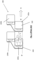
- Fig. 1 shows a prior art seating arrangement, generally designated as 100, with two seating units 102, 104, one in front of the other.
- the seating unit 102 includes two seats 102a, 102b side by side with each other but with the seat 102b slightly forward of the seat 102a; and the seating 104 includes two seats 104a, 104b side by side with each other but with the seat 104b slightly forward relative to the seat 104a. All the seats 102a, 102b, 104a, 104b face a same direction, namely the direction of travel (indicated by the arrow A in Fig. 1 ) of the transportation vehicle (e.g. aircraft) to which the seating arrangement 100 is installed.
- the transportation vehicle e.g. aircraft
- all the seats 102a, 102b, 104a, 104b face a same direction which is parallel to a line D-D which joins a component or part of the seating unit 102 and a corresponding same component or part of the seating unit 104.
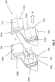
- Figs. 2 , 3 and 4 show a seating arrangement according to an embodiment of the present invention, generally designated as 200.
- the seating arrangement 200 shown in Fig. 2 includes two identically structured seating units 202, 204, with the seating unit 204 positioned in front of and parallel to the seating unit 202.
- the seating unit 202 includes two seats 206, 208 adjacent to each other, with the seat 208 slightly forward relative to the seat 206.
- the seat 206 has a seat pan 206a and a seat back 206b pivotally engaged with each other. In the configuration shown in Fig. 2 , the seat back 206b is at the back of the seat 206 and extends upwardly from the seat pan 206a.
- the seat 208 has a seat pan 208a and a seat back 208b pivotally engaged with each other.
- the seat back 208b is at the back of the seat 208 and extends upwardly from the seat pan 208a.
- the seating unit 204 includes two seats 210, 212 adjacent to each other, with the seat 212 slightly forward relative to the seat 210.
- the seat 210 has a seat pan 210a and a seat back 210b pivotally engaged with each other.
- the seat back 210b is at the back of the seat 210 and extends upwardly from the seat pan 210a.
- the seat 212 has a seat pan 212a and a seat back 212b pivotally engaged with each other.
- the seat back 212b is at the back of the seat 212 and extends upwardly from the seat pan 212a.
- the seats 206, 208 of the seating unit 202 and the seats 210, 212 of the seating unit 204 all face a direction inclined relative to the direction of travel (as indicated by the arrow B) of the transportation vehicle. It can be seen that in the case of a passenger on the seat 104a of the prior art seating unit 104 of the prior art seating arrangement 100, the furthest that he/she can see is the back of the seat 102a of the seat 102 immediately in front of him/her.
- the passenger can easily see the back of the seat 212 of the seating unit 204 immediately in front of him/her (i.e. the seat adjacent the seat immediately in front of the passenger).
- the line of sight L 2 of a passenger in the seat 206 of the seating unit 202 of the seating arrangement 200 according to the present invention is longer than the line of sight L 1 of a passenger in the seat 104a of the prior art seating unit 104 of the prior art seating arrangement 100, thus giving the passenger in the seat 206 a perception of increased spaciousness.
- the seat backs 206b, 208b, 210b, 212b are pivotally engaged with the respective seat pans 206a, 208a, 210a, 212a of the respective seats 206, 208, 210, 212.
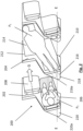
- the seat back 212b is pivoted relative to the seat pan 212a of the seat 212 away from the upwardly extending position shown in Fig. 2 to the generally horizontally extending position shown in Figs. 3 and 4
- the seat back 210b is pivoted relative to the seat pan 210a of the seat 210 away from the upwardly extending position shown in Fig. 2 to the generally horizontally extending position shown in Figs.
- back surfaces of the seat backs 206b, 210b are co-planar and conjoined with each other to collectively form a flat horizontal surface to support a passenger to lie thereon.
- a flat board or mattress 214 may be placed horizontally on and across the back surfaces of the seats 210, 212 to serve as a support on which a passenger may lie.
- the seat 210 has a space at a back portion of the seat 210.
- the seat back 210b When the seat back 210b is at the position shown in Fig. 2 in which it is at the back of the seat 210 and extends upward from the seat pan 210a, it covers the space and thus denies access to the space.
- the seat back 210b When the seat back 210b is moved away from the position shown in Fig. 2 (e.g. to the position shown in Figs. 3 and 4 ), the space is accessible from the side of the seat 210.
- the space is defined by a lower support, side walls 215 and an upper cover 216 with a horizontal, flat and upwardly facing outer surface 218.
- the space is of a generally triangular horizontal cross-section.
- the space of the seat 210 is accessible to and may be occupied by a part (e.g. feet) of an occupant (P 1 ) of the seating unit 204 lying on the support 214.
- the seats 206, 208 of the seating unit 202 and the seats 210, 212 of the seating unit 204 all face a direction (indicated by the arrow G in Fig.
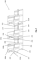
- the space at the back portion of the seat 210 effectively increases the length of a flat bed formed by the flat board or mattress 214 on which the occupant P 1 of the seating unit 204 may lie, without encroaching into the legroom of a passenger P 2 sitting on the seat 206 immediately behind the seat 210.
- the side walls 215 do not extend to the full height of the cabin of the aircraft, but that the upper cover 216 is at a level at which the outer surface 218 may serve as a small table on which the passenger P 2 may put drinks or personal items.
- the side walls 215 it is also possible to arrange the side walls 215 to extend to full height or clsoe to full height of the cabin of the aircraft so as to create more privacy.
Landscapes
- Engineering & Computer Science (AREA)
- Aviation & Aerospace Engineering (AREA)
- Transportation (AREA)
- Mechanical Engineering (AREA)
- Seats For Vehicles (AREA)
Description
- This invention relates to a convertible seating unit and a seating arrangement incorporating such a convertible seating unit suitable for, but not limited to, use on transportation vehicles, e.g. aircrafts.
- It is common to arrange for more than one class of cabins in an aircraft. In addition to the relatively densely packed economy class, there is usually a separate cabin area for premium class (or business class) with a lower seating density, giving a greater seating width and legroom to satisfy passengers who can afford a higher budget.
- The configuration of such cabins, i.e. the proportion between economy class and premium class is often fixed and cannot be modified quickly and easily. On the other hand, it is of course the case that demand for seats in the economy class and that for seats in the premium class vary across different flights and different seasons. As one fixed configuration cannot fit all the flights or adapt to varying demands for premium seats and economy seats, an airline company cannot operate to maximize its profit.
- Convertible seating units have been proposed. Such seating units may be converted into seat arrangements of different seating densities, usually by adjusting the width of the seats by varying the number of seats in each row. For example,
US Patent No. 6,715,716 discloses a seat assembly in which part of a back portion of a seat of a front row is movable to form a leg support for a seat of an adjacent rear row. - However, although more legroom is available in the seat assembly of
US Patent No. 6,715,716 , such is only suitable for sleeping posture, which a passenger may not wish to adopt during most of the flight time. For hygiene reasons, passengers may not wish to occupy a seat which can be converted into a leg support. In any event, thorough cleaning of the seat of the front row is a must. Furthermore, such prior art convertible seating units do not provide sufficient differentiation between the economy-class configuration and the business-class configuration. -
WO 2006/054064 A1 discloses an aircraft seat installed in a cubicle being able to provide privacy via a hidden, sliding/pocket door drawn to a seat-side end of a divider between adjacent seats from within a facing panel of the next divider in the line of seats. The divider provides a recessed backing for the seat; whilst a return recess provides foot rest space opposite the seat. The dividers are generally S-shaped. The seat may be a double seat, in that it comprises a convertible seat and a fixed seat immediately next to each other. The fixed seat provides an alternative seating position when the convertible seat is in bed configuration and a seat for a friend when the convertible seat is in seat configuration. Not only the convertible seat, but also the fixed seat have seat belts, the latter seat's belts being provided in case of turbulence during use. The convertible seat has a seat squab, a backrest and a leg rest both pivotally connected to the seat squab. These are reclinable via a conventional mechanism. For conversion of the seat to a bed a bed portion is withdrawn from a stowed position, which may extend between the cabin deck and a shelf alongside the space between the seat squab and the foot rest, and set up over the space. When not in use, the bed portion is stowed upright beneath a lid in the shelf, with its lower/outer end located by pins in tracks. For use, the lid may be opened and the bed portion is then drawn up until the pins reach the top of the tracks. It is then swung over the space. A leg is then pivoted to the under-side of the bed portion and springs out to a strutted position, in which its distal end engages with a load bearing point provided in the floor of the cubicle for support of the distal end of the bed portion. The proximal end of the bed portion pivots into a position such that it is supported on a panel beneath the shelf. The bed portion has a rigid base, which faces the space when stowed and an upholstered top. This is level in bed configuration with the foot rest.WO 2015/155687 discloses seat units having at least one seat with an upper seat back cushion, a lower seat back cushion, and a seat pan cushion. The at least one seat is configured to transition between a seat position and a bed position. The upper seat back cushion and the lower seat back cushion are separated by a gap located between an end of each cushion when the at least one seat is in the seat position. In contrast, the ends of the cushions are flush with each other when the at least one seat is in the bed position. The seat pan cushion is positioned below a passenger's buttocks when the at least one seat transitions between the seat position and the bed position without additional adjustment by the passenger. - It is thus an object of the present invention to provide a convertible seating unit, a seating arrangement incorporating such a convertible seating unit, and a transportation vehicle incorporating such a seating arrangement in which the aforesaid shortcomings are mitigated, or at least to provide a useful alternative to the trade and public.
- According to a first aspect of the present invention, there is provided a seating unit according to independent claim 1. Further embodiments are defined in the dependent claims.
- A seating unit according to an embodiment of the present invention, a seating arrangement incorporating such a seating unit and a transportation vehicle incorporating such a seating arrangement will now be described, by way of an example only, with reference to the accompanying drawings, in which:
-
Fig. 1 is a top view of a prior art seating arrangement; -
Fig. 2 is a top view of a seating arrangement according to an embodiment of the present invention in a first configuration; -
Fig. 3 is a top view of the seating arrangement ofFig. 2 in a second configuration; and -
Fig. 4 is a side view of the seating arrangement ofFig. 3 , not showing the occupants. -
Fig. 1 shows a prior art seating arrangement, generally designated as 100, with twoseating units seating unit 102 includes twoseats seat 102b slightly forward of theseat 102a; and theseating 104 includes twoseats seat 104b slightly forward relative to theseat 104a. All theseats Fig. 1 ) of the transportation vehicle (e.g. aircraft) to which theseating arrangement 100 is installed. In addition, all theseats seating unit 102 and a corresponding same component or part of theseating unit 104. -
Figs. 2 ,3 and4 show a seating arrangement according to an embodiment of the present invention, generally designated as 200. Theseating arrangement 200 shown inFig. 2 includes two identically structuredseating units seating unit 204 positioned in front of and parallel to theseating unit 202. Theseating unit 202 includes twoseats seat 208 slightly forward relative to theseat 206. Theseat 206 has aseat pan 206a and a seat back 206b pivotally engaged with each other. In the configuration shown inFig. 2 , theseat back 206b is at the back of theseat 206 and extends upwardly from theseat pan 206a. Similarly, theseat 208 has aseat pan 208a and a seat back 208b pivotally engaged with each other. In the configuration shown inFig. 2 , theseat back 208b is at the back of theseat 208 and extends upwardly from theseat pan 208a. Theseating unit 204 includes twoseats seat 212 slightly forward relative to theseat 210. Theseat 210 has aseat pan 210a and a seat back 210b pivotally engaged with each other. In the configuration shown inFig. 2 , theseat back 210b is at the back of theseat 210 and extends upwardly from theseat pan 210a. Similarly, theseat 212 has aseat pan 212a and a seat back 212b pivotally engaged with each other. In the configuration shown inFig. 2 , theseat back 212b is at the back of theseat 212 and extends upwardly from theseat pan 212a. - When the
seating arrangement 200 is installed on a transportation vehicle (e.g. an aircraft), theseats seating unit 202 and theseats seating unit 204 all face a direction inclined relative to the direction of travel (as indicated by the arrow B) of the transportation vehicle. It can be seen that in the case of a passenger on theseat 104a of the priorart seating unit 104 of the priorart seating arrangement 100, the furthest that he/she can see is the back of theseat 102a of theseat 102 immediately in front of him/her. On the other hand, in the case of a passenger on theseat 206 of theseating unit 202 of theseating arrangement 200 according to the present invention, the passenger can easily see the back of theseat 212 of theseating unit 204 immediately in front of him/her (i.e. the seat adjacent the seat immediately in front of the passenger). By comparingFigs. 1 and2 , it can be easily seen that the line of sight L2 of a passenger in theseat 206 of theseating unit 202 of theseating arrangement 200 according to the present invention is longer than the line of sight L1 of a passenger in theseat 104a of the priorart seating unit 104 of the priorart seating arrangement 100, thus giving the passenger in theseat 206 a perception of increased spaciousness. - The
seat backs respective seat pans respective seats Fig. 3 , and using theseating unit 204 as an example, when theseat back 212b is pivoted relative to theseat pan 212a of theseat 212 away from the upwardly extending position shown inFig. 2 to the generally horizontally extending position shown inFigs. 3 and4 , and the seat back 210b is pivoted relative to theseat pan 210a of theseat 210 away from the upwardly extending position shown inFig. 2 to the generally horizontally extending position shown inFigs. 3 and4 , back surfaces of theseat backs mattress 214 may be placed horizontally on and across the back surfaces of theseats - The
seat 210 has a space at a back portion of theseat 210. When the seat back 210b is at the position shown inFig. 2 in which it is at the back of theseat 210 and extends upward from theseat pan 210a, it covers the space and thus denies access to the space. When the seat back 210b is moved away from the position shown inFig. 2 (e.g. to the position shown inFigs. 3 and4 ), the space is accessible from the side of theseat 210. The space is defined by a lower support,side walls 215 and anupper cover 216 with a horizontal, flat and upwardly facingouter surface 218. The space is of a generally triangular horizontal cross-section. By way of such an arrangement, when theseating unit 204 is converted from the configuration shown inFig. 2 to that shown inFigs. 3 and4 , the space of theseat 210 is accessible to and may be occupied by a part (e.g. feet) of an occupant (P1) of theseating unit 204 lying on thesupport 214. In theseating arrangement 200, theseats seating unit 202 and theseats seating unit 204 all face a direction (indicated by the arrow G inFig. 3 ) which is inclined by an acute angle relative to a line which joins a component or part of theseating unit 202 and a corresponding same component or part of theseating unit 204, such as a line E-E (as shown inFig. 3 ) which joins anedge 216a of theside walls 215 of the space at the back portion of theseating unit 204 and anedge 220a ofside walls 217 of a space at a back portion of theseat 206 of theseating unit 202. - By way of such an arrangement, the space at the back portion of the
seat 210 effectively increases the length of a flat bed formed by the flat board ormattress 214 on which the occupant P1 of theseating unit 204 may lie, without encroaching into the legroom of a passenger P2 sitting on theseat 206 immediately behind theseat 210. In addition, as shown inFig. 4 , theside walls 215 do not extend to the full height of the cabin of the aircraft, but that theupper cover 216 is at a level at which theouter surface 218 may serve as a small table on which the passenger P2 may put drinks or personal items. Of course, it is also possible to arrange theside walls 215 to extend to full height or clsoe to full height of the cabin of the aircraft so as to create more privacy. - It should be understood that the above only illustrates and describes an example whereby the present invention may be carried out, and that modifications and/or alterations may be made thereto without departing from the invention as claimed.
Claims (11)
- A seating unit (202, 204),wherein said seating unit includes a first seat (206, 210) and an adjacent second seat (208, 212),wherein said seating unit is convertible between a first configuration in which each of said first seat and said second seat is adapted to receive an occupant sitting thereon and a second configuration in which said first seat and said second seat are adapted to collectively support an occupant lying thereon, andwherein access to a space (215) in a back portion behind said first seat is denied when said seating unit is in said first configuration and access to said space is allowed when said seating unit is in said second configuration,characterized in that:said space is of a triangular horizontal cross-section when seen from above,said second seat (208, 212) is forward relative to said first seat (206, 210), andsaid first seat (206, 210) and said second seat (208, 212) are convertible.
- A seating unit according to Claim 1,wherein said first seat includes a first seat pan (206a, 210a) and a first seat back (206b, 210b),wherein said first seat back is movable between a first position in which said first seat is adapted to receive an occupant sitting thereon and a second position in which said first seat back extends substantially horizontally and a back surface of said first seat back faces upwardly,wherein said second seat includes a second seat pan (208a, 212a) and a second seat back (208b, 212b),wherein said second seat back is movable between a first position in which said second seat is adapted to receive an occupant sitting thereon and a second position in which said second seat back extends substantially horizontally and a back surface of said second seat back faces upwardly, andwherein when both said first seat back and said second seat back are in their second position, said first seat and second seat are adapted to collectively support an occupant lying thereon.
- A seating unit according to Claim 2,wherein said space is defined by a lower support, side walls (215) and an upper cover (216), andwherein access to said space is denied when said first seat back is in said first position and access to said space is allowed when said first seat back is in said second configuration.
- A seating unit according to Claim 3, wherein when said first seat back is in said first position, said first seat back extends generally upwardly from said first seat at a back of said first seat to prevent access to said space.
- A seating unit according to Claim 4, wherein when said first seat back is in the second position, said first seat back is away from said back of said first seat to allow access to said space.
- A seating unit according to any one of Claims 3 to 5, wherein an outer surface (218) of said upper cover is upwardly facing and is generally horizontal.
- A seating unit according to any one of Claim 3 or 6, wherein an outer surface of said upper cover is generally flat.
- A seating unit according to any one of Claims 2 to 7, wherein when both said first seat back and said second seat back are in their second position, said back surface of said first seat back and said back surface of said second seat back are adapted to collectively form a substantially co-planar surface to support an occupant lying thereon.
- A seating unit according to any one of Claims 2 to 8, wherein when both said first seat back and said second seat back are in their second position, a support (214) is positionable on said first seat and said second seat to support an occupant lying thereon.
- A seating unit arrangement (200) including at least a first seating unit (202) and a second seating unit (204),wherein each of said first seating unit and second seating unit includes at least two seats (206, 208, 210, 212), andwherein at least said first seating unit is a seating unit according to Claim 1.
- A transportation vehicle including a seating unit according to Claim 1, wherein said seats face in a direction which is inclined relative to the direction of travel of said transportation vehicle.
Applications Claiming Priority (2)
| Application Number | Priority Date | Filing Date | Title |
|---|---|---|---|
| US201562243713P | 2015-10-20 | 2015-10-20 | |
| PCT/CN2016/101856 WO2017067409A1 (en) | 2015-10-20 | 2016-10-12 | Convertible seating unit and seating arrangement |
Publications (4)
| Publication Number | Publication Date |
|---|---|
| EP3365232A1 EP3365232A1 (en) | 2018-08-29 |
| EP3365232A4 EP3365232A4 (en) | 2019-06-05 |
| EP3365232B1 true EP3365232B1 (en) | 2023-11-29 |
| EP3365232C0 EP3365232C0 (en) | 2023-11-29 |
Family
ID=58558041
Family Applications (1)
| Application Number | Title | Priority Date | Filing Date |
|---|---|---|---|
| EP16856841.8A Active EP3365232B1 (en) | 2015-10-20 | 2016-10-12 | Convertible seating unit and seating arrangement |
Country Status (4)
| Country | Link |
|---|---|
| US (1) | US10696409B2 (en) |
| EP (1) | EP3365232B1 (en) |
| JP (1) | JP2018537362A (en) |
| WO (1) | WO2017067409A1 (en) |
Families Citing this family (7)
| Publication number | Priority date | Publication date | Assignee | Title |
|---|---|---|---|---|
| GB2572446A (en) | 2018-03-30 | 2019-10-02 | Acumen Design Ass Ltd | A passenger seating arrangement having access for disabled passengers |
| GB2572556A (en) | 2018-03-30 | 2019-10-09 | Acumen Design Ass Ltd | A passenger seating arrangement having a screen between seat units |
| US10549858B2 (en) * | 2018-06-06 | 2020-02-04 | The Boeing Company | Seat pan for an aircraft |
| FR3088900B1 (en) * | 2018-11-23 | 2023-07-14 | Zodiac Seats France | SET OF SEATS, PARTICULARLY FOR AN AIRPLANE |
| CN111591450B (en) * | 2020-05-29 | 2022-02-08 | 中国商用飞机有限责任公司 | Dining table board assembly, fishbone type seat set and fishbone type seat system |
| US12459650B2 (en) * | 2023-06-23 | 2025-11-04 | B/E Aerospace, Inc. | Converting economy seat to full flat bed by dropping seat back frame |
| US12351317B2 (en) | 2023-08-08 | 2025-07-08 | B/E Aerospace, Inc. | Row of passenger seats convertible to a bed |
Family Cites Families (41)
| Publication number | Priority date | Publication date | Assignee | Title |
|---|---|---|---|---|
| JPS5822341U (en) * | 1981-08-05 | 1983-02-12 | 池田物産株式会社 | vehicle seat |
| GB9617706D0 (en) * | 1996-08-22 | 1996-10-02 | Britax Rumbold Ltd | Vehicle seat |
| US6692069B2 (en) * | 2001-07-20 | 2004-02-17 | B E Aerospace, Inc. | Aircraft sleeper seat |
| ATE363409T1 (en) * | 2001-08-09 | 2007-06-15 | Virgin Atlantic Airways Ltd | A SEATING ARRANGEMENT AND A PASSENGER ACCOMMODATION UNIT FOR A VEHICLE |
| ATE328756T1 (en) | 2001-12-20 | 2006-06-15 | James Thompson | SEATING ARRANGEMENT IN A VEHICLE |
| US6715716B1 (en) | 2002-09-17 | 2004-04-06 | The Boeing Company | Economy aircraft sleeper seat |
| GB0316733D0 (en) * | 2003-07-17 | 2003-08-20 | Thompson James | Seating for a passenger vehicle |
| JP4175474B2 (en) * | 2004-02-05 | 2008-11-05 | 三菱重工業株式会社 | Aircraft, moving body |
| GB0425323D0 (en) | 2004-11-17 | 2004-12-22 | Britax Aircraft Interiors Uk L | Aircraft seat |
| DE102005022165B4 (en) * | 2005-05-13 | 2007-05-03 | Recaro Aircraft Seating Gmbh & Co. Kg | Seat, in particular passenger seat |
| US7721990B2 (en) * | 2005-07-29 | 2010-05-25 | Airbus Deutschland Gmbh | Passenger compartment |
| JP2009504510A (en) * | 2005-08-22 | 2009-02-05 | ビー イー エアロスペイス,インク. | Lounge seat arrangement structure |
| EP1759991A1 (en) * | 2005-08-31 | 2007-03-07 | Lufthansa Technik AG | Arrangement for seating and lying down |
| CA2630000C (en) * | 2005-11-24 | 2012-09-25 | Singapore Airlines Limited | Aircraft seating and seating arrangements |
| US7578470B2 (en) * | 2006-04-21 | 2009-08-25 | Be Aerospace, Inc. | Passenger seating arrangement |
| GB2438162A (en) | 2006-05-19 | 2007-11-21 | British Airways Plc | Reclining aircraft seat convertible into bed |
| US7975962B2 (en) * | 2007-09-11 | 2011-07-12 | Emil Jacob | Transportation vehicle passenger accommodation assembly |
| WO2009067028A2 (en) * | 2007-11-21 | 2009-05-28 | Air New Zealand Limited | Improvements relating to vehicle seating apparatus |
| FR2924683A1 (en) * | 2007-12-06 | 2009-06-12 | Airbus Sas | Cabin for e.g. double-aisle aircraft, has passenger seats arranged in rows that are inclined with respect to longitudinal aisles, where seats of each row are arranged side by side and oriented perpendicular to row and towards aisles |
| US20090146004A1 (en) * | 2007-12-06 | 2009-06-11 | B E Aerospace, Inc. | Aircraft seating arrangement and seat |
| FR2928624B1 (en) * | 2008-03-17 | 2016-07-15 | Soc Ind Et Commerciale De Materiel Aeronautique - Sicma Aero Seat | ARRANGEMENT OF SEAT ARMREST IN SECURE PURPOSE SEAT AND ASSEMBLY OF TWO SEATS WITH SUCH ARRANGEMENT. |
| FR2934564B1 (en) * | 2008-08-01 | 2011-05-06 | Airbus | SEAT MODULE FOR PASSENGER AIRCRAFT |
| US8245970B2 (en) * | 2008-08-11 | 2012-08-21 | American Airlines, Inc. | Array of aircraft seats |
| GB0903744D0 (en) * | 2009-03-04 | 2009-04-15 | Virgin Atlantic Airways Ltd | A seating insallation for a passenger vehicle |
| GB2469180B8 (en) * | 2009-03-23 | 2016-06-08 | Air New Zealand Ltd | Vehicle seating arrangement |
| FR2953168B1 (en) * | 2009-12-02 | 2012-01-06 | Eads Sogerma | CONVERTIBLE SEAT IN SLEEVE |
| US8882035B2 (en) * | 2010-01-22 | 2014-11-11 | James Dominic France | Class divider |
| US8882036B2 (en) * | 2011-03-03 | 2014-11-11 | Robert J. Henshaw | Aircraft seating arrangement |
| US8936214B2 (en) * | 2011-04-15 | 2015-01-20 | Zodiac Seats France | Passenger seating arrangements |
| US8944379B2 (en) * | 2011-10-28 | 2015-02-03 | Zodiac Seat Shells Us Llc | Aircraft seating configuration |
| GB2500258B (en) * | 2012-03-16 | 2019-05-08 | Zodiac Seats Uk Ltd | High density aircraft seat arrangement |
| GB201217319D0 (en) * | 2012-09-27 | 2012-11-14 | Acumen Design Associates Ltd | Aircraft passenger seating arrangement |
| US9889936B2 (en) | 2012-10-30 | 2018-02-13 | The Boeing Company | Curved seating layout |
| WO2014115107A1 (en) * | 2013-01-23 | 2014-07-31 | Zodiac Seats France | Bed extension |
| FR3003540B1 (en) | 2013-03-25 | 2015-05-29 | Eads Sogerma | ARRANGEMENT OF CONVERTIBLE SEATS IN LAYERS |
| GB201306432D0 (en) * | 2013-04-09 | 2013-05-22 | James Park Associates Ltd | Personal units |
| US10556689B2 (en) * | 2013-12-03 | 2020-02-11 | Butterfly Flexible Seating Solutions Limited | Convertible seating unit |
| US10315772B2 (en) | 2014-04-07 | 2019-06-11 | Zodiac Seats France | Seat unit |
| US9409648B2 (en) * | 2014-05-15 | 2016-08-09 | The Boeing Company | Seating arrangement and method |
| EP2965990A1 (en) * | 2014-07-08 | 2016-01-13 | Airbus Operations GmbH | Passenger seat for a means of transportation |
| EP2974961B1 (en) * | 2014-07-15 | 2017-04-26 | Airbus Defence and Space GmbH | Seat assembly, seat arrangement and passenger cabin for an aircraft |
-
2016
- 2016-10-12 WO PCT/CN2016/101856 patent/WO2017067409A1/en not_active Ceased
- 2016-10-12 JP JP2018540200A patent/JP2018537362A/en active Pending
- 2016-10-12 US US15/769,994 patent/US10696409B2/en active Active
- 2016-10-12 EP EP16856841.8A patent/EP3365232B1/en active Active
Also Published As
| Publication number | Publication date |
|---|---|
| WO2017067409A1 (en) | 2017-04-27 |
| EP3365232A1 (en) | 2018-08-29 |
| EP3365232C0 (en) | 2023-11-29 |
| CA3040982A1 (en) | 2017-04-27 |
| US20180281969A1 (en) | 2018-10-04 |
| US10696409B2 (en) | 2020-06-30 |
| JP2018537362A (en) | 2018-12-20 |
| EP3365232A4 (en) | 2019-06-05 |
Similar Documents
| Publication | Publication Date | Title |
|---|---|---|
| EP3365232B1 (en) | Convertible seating unit and seating arrangement | |
| US11130577B2 (en) | Universal rest seats | |
| US8662447B2 (en) | Flexible-usage travel suite | |
| EP3092174B1 (en) | Aircraft passenger seating arrangement | |
| CA2586087C (en) | Aircraft seat | |
| EP1495908B1 (en) | A seating system and a passenger accomodation unit for a vehicle | |
| US9126689B2 (en) | Vehicle passenger seating | |
| US8342450B2 (en) | Seating arrangement of a vehicle compartment | |
| US20250051012A1 (en) | Conjoinable reverse herringbone passenger seat | |
| CA3040982C (en) | Convertible seating unit and seating arrangement | |
| US11006760B2 (en) | Convertible seating unit and seating arrangement | |
| HK1068209C (en) | A seating system and a passenger accomodation unit for a vehicle | |
| HK1068209B (en) | A seating system and a passenger accomodation unit for a vehicle |
Legal Events
| Date | Code | Title | Description |
|---|---|---|---|
| STAA | Information on the status of an ep patent application or granted ep patent |
Free format text: STATUS: THE INTERNATIONAL PUBLICATION HAS BEEN MADE |
|
| PUAI | Public reference made under article 153(3) epc to a published international application that has entered the european phase |
Free format text: ORIGINAL CODE: 0009012 |
|
| STAA | Information on the status of an ep patent application or granted ep patent |
Free format text: STATUS: REQUEST FOR EXAMINATION WAS MADE |
|
| 17P | Request for examination filed |
Effective date: 20180511 |
|
| AK | Designated contracting states |
Kind code of ref document: A1 Designated state(s): AL AT BE BG CH CY CZ DE DK EE ES FI FR GB GR HR HU IE IS IT LI LT LU LV MC MK MT NL NO PL PT RO RS SE SI SK SM TR |
|
| AX | Request for extension of the european patent |
Extension state: BA ME |
|
| DAV | Request for validation of the european patent (deleted) | ||
| DAX | Request for extension of the european patent (deleted) | ||
| A4 | Supplementary search report drawn up and despatched |
Effective date: 20190506 |
|
| RIC1 | Information provided on ipc code assigned before grant |
Ipc: B64D 11/06 20060101AFI20190429BHEP |
|
| STAA | Information on the status of an ep patent application or granted ep patent |
Free format text: STATUS: EXAMINATION IS IN PROGRESS |
|
| 17Q | First examination report despatched |
Effective date: 20210212 |
|
| GRAP | Despatch of communication of intention to grant a patent |
Free format text: ORIGINAL CODE: EPIDOSNIGR1 |
|
| STAA | Information on the status of an ep patent application or granted ep patent |
Free format text: STATUS: GRANT OF PATENT IS INTENDED |
|
| P01 | Opt-out of the competence of the unified patent court (upc) registered |
Effective date: 20230303 |
|
| INTG | Intention to grant announced |
Effective date: 20230524 |
|
| GRAS | Grant fee paid |
Free format text: ORIGINAL CODE: EPIDOSNIGR3 |
|
| GRAA | (expected) grant |
Free format text: ORIGINAL CODE: 0009210 |
|
| STAA | Information on the status of an ep patent application or granted ep patent |
Free format text: STATUS: THE PATENT HAS BEEN GRANTED |
|
| AK | Designated contracting states |
Kind code of ref document: B1 Designated state(s): AL AT BE BG CH CY CZ DE DK EE ES FI FR GB GR HR HU IE IS IT LI LT LU LV MC MK MT NL NO PL PT RO RS SE SI SK SM TR |
|
| REG | Reference to a national code |
Ref country code: GB Ref legal event code: FG4D |
|
| REG | Reference to a national code |
Ref country code: CH Ref legal event code: EP |
|
| REG | Reference to a national code |
Ref country code: DE Ref legal event code: R096 Ref document number: 602016084449 Country of ref document: DE |
|
| REG | Reference to a national code |
Ref country code: IE Ref legal event code: FG4D |
|
| U01 | Request for unitary effect filed |
Effective date: 20231222 |
|
| U07 | Unitary effect registered |
Designated state(s): AT BE BG DE DK EE FI FR IT LT LU LV MT NL PT SE SI Effective date: 20240109 |
|
| P04 | Withdrawal of opt-out of the competence of the unified patent court (upc) registered |
Effective date: 20240105 |
|
| PG25 | Lapsed in a contracting state [announced via postgrant information from national office to epo] |
Ref country code: GR Free format text: LAPSE BECAUSE OF FAILURE TO SUBMIT A TRANSLATION OF THE DESCRIPTION OR TO PAY THE FEE WITHIN THE PRESCRIBED TIME-LIMIT Effective date: 20240301 |
|
| PG25 | Lapsed in a contracting state [announced via postgrant information from national office to epo] |
Ref country code: IS Free format text: LAPSE BECAUSE OF FAILURE TO SUBMIT A TRANSLATION OF THE DESCRIPTION OR TO PAY THE FEE WITHIN THE PRESCRIBED TIME-LIMIT Effective date: 20240329 |
|
| PG25 | Lapsed in a contracting state [announced via postgrant information from national office to epo] |
Ref country code: ES Free format text: LAPSE BECAUSE OF FAILURE TO SUBMIT A TRANSLATION OF THE DESCRIPTION OR TO PAY THE FEE WITHIN THE PRESCRIBED TIME-LIMIT Effective date: 20231129 |
|
| PG25 | Lapsed in a contracting state [announced via postgrant information from national office to epo] |
Ref country code: IS Free format text: LAPSE BECAUSE OF FAILURE TO SUBMIT A TRANSLATION OF THE DESCRIPTION OR TO PAY THE FEE WITHIN THE PRESCRIBED TIME-LIMIT Effective date: 20240329 Ref country code: GR Free format text: LAPSE BECAUSE OF FAILURE TO SUBMIT A TRANSLATION OF THE DESCRIPTION OR TO PAY THE FEE WITHIN THE PRESCRIBED TIME-LIMIT Effective date: 20240301 Ref country code: ES Free format text: LAPSE BECAUSE OF FAILURE TO SUBMIT A TRANSLATION OF THE DESCRIPTION OR TO PAY THE FEE WITHIN THE PRESCRIBED TIME-LIMIT Effective date: 20231129 |
|
| PG25 | Lapsed in a contracting state [announced via postgrant information from national office to epo] |
Ref country code: RS Free format text: LAPSE BECAUSE OF FAILURE TO SUBMIT A TRANSLATION OF THE DESCRIPTION OR TO PAY THE FEE WITHIN THE PRESCRIBED TIME-LIMIT Effective date: 20231129 Ref country code: PL Free format text: LAPSE BECAUSE OF FAILURE TO SUBMIT A TRANSLATION OF THE DESCRIPTION OR TO PAY THE FEE WITHIN THE PRESCRIBED TIME-LIMIT Effective date: 20231129 Ref country code: NO Free format text: LAPSE BECAUSE OF FAILURE TO SUBMIT A TRANSLATION OF THE DESCRIPTION OR TO PAY THE FEE WITHIN THE PRESCRIBED TIME-LIMIT Effective date: 20240229 Ref country code: HR Free format text: LAPSE BECAUSE OF FAILURE TO SUBMIT A TRANSLATION OF THE DESCRIPTION OR TO PAY THE FEE WITHIN THE PRESCRIBED TIME-LIMIT Effective date: 20231129 |
|
| PG25 | Lapsed in a contracting state [announced via postgrant information from national office to epo] |
Ref country code: CZ Free format text: LAPSE BECAUSE OF FAILURE TO SUBMIT A TRANSLATION OF THE DESCRIPTION OR TO PAY THE FEE WITHIN THE PRESCRIBED TIME-LIMIT Effective date: 20231129 |
|
| PG25 | Lapsed in a contracting state [announced via postgrant information from national office to epo] |
Ref country code: SK Free format text: LAPSE BECAUSE OF FAILURE TO SUBMIT A TRANSLATION OF THE DESCRIPTION OR TO PAY THE FEE WITHIN THE PRESCRIBED TIME-LIMIT Effective date: 20231129 |
|
| PG25 | Lapsed in a contracting state [announced via postgrant information from national office to epo] |
Ref country code: SM Free format text: LAPSE BECAUSE OF FAILURE TO SUBMIT A TRANSLATION OF THE DESCRIPTION OR TO PAY THE FEE WITHIN THE PRESCRIBED TIME-LIMIT Effective date: 20231129 Ref country code: SK Free format text: LAPSE BECAUSE OF FAILURE TO SUBMIT A TRANSLATION OF THE DESCRIPTION OR TO PAY THE FEE WITHIN THE PRESCRIBED TIME-LIMIT Effective date: 20231129 Ref country code: RO Free format text: LAPSE BECAUSE OF FAILURE TO SUBMIT A TRANSLATION OF THE DESCRIPTION OR TO PAY THE FEE WITHIN THE PRESCRIBED TIME-LIMIT Effective date: 20231129 Ref country code: CZ Free format text: LAPSE BECAUSE OF FAILURE TO SUBMIT A TRANSLATION OF THE DESCRIPTION OR TO PAY THE FEE WITHIN THE PRESCRIBED TIME-LIMIT Effective date: 20231129 |
|
| REG | Reference to a national code |
Ref country code: DE Ref legal event code: R097 Ref document number: 602016084449 Country of ref document: DE |
|
| PLBE | No opposition filed within time limit |
Free format text: ORIGINAL CODE: 0009261 |
|
| STAA | Information on the status of an ep patent application or granted ep patent |
Free format text: STATUS: NO OPPOSITION FILED WITHIN TIME LIMIT |
|
| 26N | No opposition filed |
Effective date: 20240830 |
|
| U20 | Renewal fee for the european patent with unitary effect paid |
Year of fee payment: 9 Effective date: 20241025 |
|
| P05 | Withdrawal of opt-out of the competence of the unified patent court (upc) changed |
Free format text: CASE NUMBER: APP_493/2024 Effective date: 20240109 |
|
| PGFP | Annual fee paid to national office [announced via postgrant information from national office to epo] |
Ref country code: GB Payment date: 20241025 Year of fee payment: 9 |
|
| PGFP | Annual fee paid to national office [announced via postgrant information from national office to epo] |
Ref country code: TR Payment date: 20241004 Year of fee payment: 9 |
|
| REG | Reference to a national code |
Ref country code: CH Ref legal event code: PL |
|
| PG25 | Lapsed in a contracting state [announced via postgrant information from national office to epo] |
Ref country code: MC Free format text: LAPSE BECAUSE OF FAILURE TO SUBMIT A TRANSLATION OF THE DESCRIPTION OR TO PAY THE FEE WITHIN THE PRESCRIBED TIME-LIMIT Effective date: 20231129 |
|
| PG25 | Lapsed in a contracting state [announced via postgrant information from national office to epo] |
Ref country code: CH Free format text: LAPSE BECAUSE OF NON-PAYMENT OF DUE FEES Effective date: 20241031 |
|
| PG25 | Lapsed in a contracting state [announced via postgrant information from national office to epo] |
Ref country code: IE Free format text: LAPSE BECAUSE OF NON-PAYMENT OF DUE FEES Effective date: 20241012 |
|
| U20 | Renewal fee for the european patent with unitary effect paid |
Year of fee payment: 10 Effective date: 20251028 |
|
| PG25 | Lapsed in a contracting state [announced via postgrant information from national office to epo] |
Ref country code: CY Free format text: LAPSE BECAUSE OF FAILURE TO SUBMIT A TRANSLATION OF THE DESCRIPTION OR TO PAY THE FEE WITHIN THE PRESCRIBED TIME-LIMIT; INVALID AB INITIO Effective date: 20161012 |
|
| PG25 | Lapsed in a contracting state [announced via postgrant information from national office to epo] |
Ref country code: HU Free format text: LAPSE BECAUSE OF FAILURE TO SUBMIT A TRANSLATION OF THE DESCRIPTION OR TO PAY THE FEE WITHIN THE PRESCRIBED TIME-LIMIT; INVALID AB INITIO Effective date: 20161012 |