EP3365081B1 - Bilateral hand rehabilitation device and system - Google Patents
Bilateral hand rehabilitation device and system Download PDFInfo
- Publication number
- EP3365081B1 EP3365081B1 EP16868130.2A EP16868130A EP3365081B1 EP 3365081 B1 EP3365081 B1 EP 3365081B1 EP 16868130 A EP16868130 A EP 16868130A EP 3365081 B1 EP3365081 B1 EP 3365081B1
- Authority
- EP
- European Patent Office
- Prior art keywords
- handlebar
- members
- rehabilitation device
- finger grip
- assembly
- Prior art date
- Legal status (The legal status is an assumption and is not a legal conclusion. Google has not performed a legal analysis and makes no representation as to the accuracy of the status listed.)
- Active
Links
Images






Classifications
-
- A—HUMAN NECESSITIES
- A63—SPORTS; GAMES; AMUSEMENTS
- A63B—APPARATUS FOR PHYSICAL TRAINING, GYMNASTICS, SWIMMING, CLIMBING, OR FENCING; BALL GAMES; TRAINING EQUIPMENT
- A63B21/00—Exercising apparatus for developing or strengthening the muscles or joints of the body by working against a counterforce, with or without measuring devices
- A63B21/40—Interfaces with the user related to strength training; Details thereof
- A63B21/4027—Specific exercise interfaces
- A63B21/4033—Handles, pedals, bars or platforms
- A63B21/4035—Handles, pedals, bars or platforms for operation by hand
-
- A—HUMAN NECESSITIES
- A63—SPORTS; GAMES; AMUSEMENTS
- A63B—APPARATUS FOR PHYSICAL TRAINING, GYMNASTICS, SWIMMING, CLIMBING, OR FENCING; BALL GAMES; TRAINING EQUIPMENT
- A63B21/00—Exercising apparatus for developing or strengthening the muscles or joints of the body by working against a counterforce, with or without measuring devices
- A63B21/40—Interfaces with the user related to strength training; Details thereof
- A63B21/4041—Interfaces with the user related to strength training; Details thereof characterised by the movements of the interface
- A63B21/4047—Pivoting movement
-
- A—HUMAN NECESSITIES
- A63—SPORTS; GAMES; AMUSEMENTS
- A63B—APPARATUS FOR PHYSICAL TRAINING, GYMNASTICS, SWIMMING, CLIMBING, OR FENCING; BALL GAMES; TRAINING EQUIPMENT
- A63B23/00—Exercising apparatus specially adapted for particular parts of the body
- A63B23/035—Exercising apparatus specially adapted for particular parts of the body for limbs, i.e. upper or lower limbs, e.g. simultaneously
- A63B23/03516—For both arms together or both legs together; Aspects related to the co-ordination between right and left side limbs of a user
- A63B23/03533—With separate means driven by each limb, i.e. performing different movements
-
- A—HUMAN NECESSITIES
- A63—SPORTS; GAMES; AMUSEMENTS
- A63B—APPARATUS FOR PHYSICAL TRAINING, GYMNASTICS, SWIMMING, CLIMBING, OR FENCING; BALL GAMES; TRAINING EQUIPMENT
- A63B23/00—Exercising apparatus specially adapted for particular parts of the body
- A63B23/035—Exercising apparatus specially adapted for particular parts of the body for limbs, i.e. upper or lower limbs, e.g. simultaneously
- A63B23/12—Exercising apparatus specially adapted for particular parts of the body for limbs, i.e. upper or lower limbs, e.g. simultaneously for upper limbs or related muscles, e.g. chest, upper back or shoulder muscles
- A63B23/16—Exercising apparatus specially adapted for particular parts of the body for limbs, i.e. upper or lower limbs, e.g. simultaneously for upper limbs or related muscles, e.g. chest, upper back or shoulder muscles for hands or fingers
-
- A—HUMAN NECESSITIES
- A63—SPORTS; GAMES; AMUSEMENTS
- A63B—APPARATUS FOR PHYSICAL TRAINING, GYMNASTICS, SWIMMING, CLIMBING, OR FENCING; BALL GAMES; TRAINING EQUIPMENT
- A63B71/00—Games or sports accessories not covered in groups A63B1/00 - A63B69/00
- A63B71/0009—Games or sports accessories not covered in groups A63B1/00 - A63B69/00 for handicapped persons
-
- A—HUMAN NECESSITIES
- A63—SPORTS; GAMES; AMUSEMENTS
- A63F—CARD, BOARD, OR ROULETTE GAMES; INDOOR GAMES USING SMALL MOVING PLAYING BODIES; VIDEO GAMES; GAMES NOT OTHERWISE PROVIDED FOR
- A63F13/00—Video games, i.e. games using an electronically generated display having two or more dimensions
- A63F13/20—Input arrangements for video game devices
- A63F13/24—Constructional details thereof, e.g. game controllers with detachable joystick handles
-
- A—HUMAN NECESSITIES
- A63—SPORTS; GAMES; AMUSEMENTS
- A63B—APPARATUS FOR PHYSICAL TRAINING, GYMNASTICS, SWIMMING, CLIMBING, OR FENCING; BALL GAMES; TRAINING EQUIPMENT
- A63B21/00—Exercising apparatus for developing or strengthening the muscles or joints of the body by working against a counterforce, with or without measuring devices
- A63B21/15—Arrangements for force transmissions
- A63B21/157—Ratchet-wheel links; Overrunning clutches; One-way clutches
-
- A—HUMAN NECESSITIES
- A63—SPORTS; GAMES; AMUSEMENTS
- A63B—APPARATUS FOR PHYSICAL TRAINING, GYMNASTICS, SWIMMING, CLIMBING, OR FENCING; BALL GAMES; TRAINING EQUIPMENT
- A63B21/00—Exercising apparatus for developing or strengthening the muscles or joints of the body by working against a counterforce, with or without measuring devices
- A63B21/16—Supports for anchoring force-resisters
-
- A—HUMAN NECESSITIES
- A63—SPORTS; GAMES; AMUSEMENTS
- A63B—APPARATUS FOR PHYSICAL TRAINING, GYMNASTICS, SWIMMING, CLIMBING, OR FENCING; BALL GAMES; TRAINING EQUIPMENT
- A63B21/00—Exercising apparatus for developing or strengthening the muscles or joints of the body by working against a counterforce, with or without measuring devices
- A63B21/16—Supports for anchoring force-resisters
- A63B21/169—Supports for anchoring force-resisters for anchoring on or against a wall
-
- A—HUMAN NECESSITIES
- A63—SPORTS; GAMES; AMUSEMENTS
- A63B—APPARATUS FOR PHYSICAL TRAINING, GYMNASTICS, SWIMMING, CLIMBING, OR FENCING; BALL GAMES; TRAINING EQUIPMENT
- A63B2220/00—Measuring of physical parameters relating to sporting activity
- A63B2220/10—Positions
-
- A—HUMAN NECESSITIES
- A63—SPORTS; GAMES; AMUSEMENTS
- A63B—APPARATUS FOR PHYSICAL TRAINING, GYMNASTICS, SWIMMING, CLIMBING, OR FENCING; BALL GAMES; TRAINING EQUIPMENT
- A63B2220/00—Measuring of physical parameters relating to sporting activity
- A63B2220/10—Positions
- A63B2220/16—Angular positions
-
- A—HUMAN NECESSITIES
- A63—SPORTS; GAMES; AMUSEMENTS
- A63B—APPARATUS FOR PHYSICAL TRAINING, GYMNASTICS, SWIMMING, CLIMBING, OR FENCING; BALL GAMES; TRAINING EQUIPMENT
- A63B2220/00—Measuring of physical parameters relating to sporting activity
- A63B2220/30—Speed
- A63B2220/36—Speed measurement by electric or magnetic parameters
-
- A—HUMAN NECESSITIES
- A63—SPORTS; GAMES; AMUSEMENTS
- A63B—APPARATUS FOR PHYSICAL TRAINING, GYMNASTICS, SWIMMING, CLIMBING, OR FENCING; BALL GAMES; TRAINING EQUIPMENT
- A63B2220/00—Measuring of physical parameters relating to sporting activity
- A63B2220/40—Acceleration
-
- A—HUMAN NECESSITIES
- A63—SPORTS; GAMES; AMUSEMENTS
- A63B—APPARATUS FOR PHYSICAL TRAINING, GYMNASTICS, SWIMMING, CLIMBING, OR FENCING; BALL GAMES; TRAINING EQUIPMENT
- A63B2220/00—Measuring of physical parameters relating to sporting activity
- A63B2220/50—Force related parameters
- A63B2220/51—Force
-
- A—HUMAN NECESSITIES
- A63—SPORTS; GAMES; AMUSEMENTS
- A63B—APPARATUS FOR PHYSICAL TRAINING, GYMNASTICS, SWIMMING, CLIMBING, OR FENCING; BALL GAMES; TRAINING EQUIPMENT
- A63B2220/00—Measuring of physical parameters relating to sporting activity
- A63B2220/50—Force related parameters
- A63B2220/58—Measurement of force related parameters by electric or magnetic means
-
- A—HUMAN NECESSITIES
- A63—SPORTS; GAMES; AMUSEMENTS
- A63B—APPARATUS FOR PHYSICAL TRAINING, GYMNASTICS, SWIMMING, CLIMBING, OR FENCING; BALL GAMES; TRAINING EQUIPMENT
- A63B2220/00—Measuring of physical parameters relating to sporting activity
- A63B2220/80—Special sensors, transducers or devices therefor
- A63B2220/801—Contact switches
-
- A—HUMAN NECESSITIES
- A63—SPORTS; GAMES; AMUSEMENTS
- A63B—APPARATUS FOR PHYSICAL TRAINING, GYMNASTICS, SWIMMING, CLIMBING, OR FENCING; BALL GAMES; TRAINING EQUIPMENT
- A63B2225/00—Miscellaneous features of sport apparatus, devices or equipment
- A63B2225/09—Adjustable dimensions
-
- A—HUMAN NECESSITIES
- A63—SPORTS; GAMES; AMUSEMENTS
- A63B—APPARATUS FOR PHYSICAL TRAINING, GYMNASTICS, SWIMMING, CLIMBING, OR FENCING; BALL GAMES; TRAINING EQUIPMENT
- A63B2225/00—Miscellaneous features of sport apparatus, devices or equipment
- A63B2225/50—Wireless data transmission, e.g. by radio transmitters or telemetry
-
- A—HUMAN NECESSITIES
- A63—SPORTS; GAMES; AMUSEMENTS
- A63B—APPARATUS FOR PHYSICAL TRAINING, GYMNASTICS, SWIMMING, CLIMBING, OR FENCING; BALL GAMES; TRAINING EQUIPMENT
- A63B71/00—Games or sports accessories not covered in groups A63B1/00 - A63B69/00
- A63B71/06—Indicating or scoring devices for games or players, or for other sports activities
- A63B71/0619—Displays, user interfaces and indicating devices, specially adapted for sport equipment, e.g. display mounted on treadmills
- A63B71/0622—Visual, audio or audio-visual systems for entertaining, instructing or motivating the user
Definitions
- This invention relates to a rehabilitation device and system for hands.
- a patient with hemiparesis is typically able to move one arm in a normal manner, but the other arm on the opposite side of their body is at least partially paralysed.
- the paralysis of the arm is caused by damage to the brain in areas that control the arm or that side of the body. Physically, there is actually nothing actually wrong with the paralysed limb.
- Neuroplastic recovery from brain injury and the rehabilitation of an affected arm by bilateral relearning and cortical remodeling is well known. Briefly, this involves retraining undamaged parts of the brain, which previously carried out different functions from controlling limbs, to control the paralysed limbs.
- Neuroplasticity is the fundamental issue that supports the scientific basis for treatment of acquired brain injury with goal-directed experiential therapeutic programs in the context of rehabilitation approaches to the functional consequences of the injury.
- a hand grip strengthening and competition apparatus is disclosed in US patent no. 7438669 .
- the apparatus is provided with a pair of levers mounted to an elongate body for pivotal movement between an open and closed position.
- An elongate, substantially non-stretchable connector is attached to each lever and prevents the pair of levers from concurrently assuming their respective closed positions.
- US patent no. 3653659 and US patent no. 2643123 each disclose an exercising device for exercising the grip and the muscles of the forearm having two connected bars, one which is pivotable with respect to the other.
- US patent application no. 2009/0191967 discloses a game apparatus which incorporates a tilt sensor and a motocross or motorcycle style left and right grip as input.
- the invention relates to a bilateral hand rehabilitation device as claimed in claim 1.
- the handlebar members are spaced-apart from one another and are separate members. In another embodiment, the handlebar members may be portions or parts of a common member or integral with each other.
- the handlebar members have longitudinal axes that are parallel to each other.
- the handlebar members are vertical or upright members.
- the handlebar members need not be parallel to each other, but may have longitudinal axes that extend at an angle either toward or away from one another, or may have longitudinal axes that are co-axial such that they are aligned in a common axis, e.g. horizontally-orientated handlebars.
- the pair of handlebar members are provided on or mounted to a common base.
- the base may be substantially planar and the handlebars may extend vertically upward from the planar base.
- a horizontal upper crossbar member may extend between the upper ends of the handlebar members.
- the finger grip members are pivotally mounted for pivotal or arced movement toward and away from their respective handlebar members.
- the path or range of pivotal movement is restricted between a closed or grasp position at or toward the handlebar member, and an open or release position displaced away from the handlebar member.
- each finger grip member is offset relative to the longitudinal axis of its respective handlebar member.
- the pivot axis of the finger grip member may be offset into substantial alignment with the knuckles of hands of a user of the device.
- the handlebar members are provided in a handlebar assembly that comprises the base, handlebar members and the upper crossbar member.
- the finger grip members further comprise upper and lower transverse connecting plates that are coupled to the upper and lower ends of each respective finger grip member to provide respective finger grip assemblies.
- the finger grip assemblies are pivotally mounted adjacent or relative to their respective handlebar members on opposite sides of the handlebar assembly via pivotal connections or couplings between the upper and lower connecting plates of each finger grip assembly and respective upper and lower portions of the handlebar assembly.
- the handlebar members are configured to engage the palm and/or thumb of the hands of a user.
- the finger grip members are configured to engage or be gripped by the inner finger surfaces of the hands of a user.
- each finger grip assembly further comprises a vertical release member that extends between the upper and lower connecting plates and which is offset from the finger grip member.
- the release member is configured to engage or face the outer or dorsal finger surfaces of the hands of a user when in use. In one configuration, the position and orientation of the release member relative to the finger grip member may be adjusted.
- the longitudinal axis of the release members are parallel to the finger grip members and handlebar members.
- the handlebar members, finger grip members, and asymmetric connection mechanism are parts of a hand grip assembly, and the hand grip assembly is pivotally mounted to a mounting assembly.
- the mounting assembly provides the hand grip assembly with at least one degree of pivotal movement, but preferably two or more degrees of pivotal movement.
- the mounting assembly enables the hand grip assembly to rotate relative to at least one pivot axis defined by the mounting assembly.
- the hand grip assembly is pivotal relative to two orthogonal pivot axes provided by the mounting assembly.
- the two pivot axes are spaced-apart.
- the mounting assembly provides a first pivot axis extending in the bisecting plane between the handlebar members of the handlebar assembly, to enable the hand grip assembly to be tilted from side to side (i.e. rotated either clockwise or anti-clockwise about the first pivot axis), and a second pivot axis that is a transverse orientation relative to the first pivot axis and which allows the hand grip assembly to pivot back and forth (i.e. rotate clockwise or anti-clockwise about the second transverse pivot axis).
- the first pivot axis extends in a plane that corresponds to the sagittal plane of the user of the device
- the second pivot axis extends in a plane parallel to the coronal plane of the user of the device.
- the mounting assembly comprises a base that is releasably securable to a support surface or structure, such as a table or other horizontal support surface or similar.
- the base comprises one or more clamping mechanisms to secure the base to the support surface or structure.
- the mounting assembly further comprises a link member having two ends, the link member being pivotally coupled to the base at or toward one end, and pivotally coupled to the hand grip assembly at or toward the other end.
- the pivot axes defined by the pivotal couplings or connections at the first and second ends of the link member are transverse to each other to provide the first and second transverse pivot axes of the mounting assembly.
- the bilateral hand rehabilitation device further comprises one or more movement or rotation or position sensors, load sensors, and/or switches that are configured to sense interaction with the bilateral hand rehabilitation device by a user.
- the bilateral hand rehabilitation device is operatively connected to an interactive gaming system and the output signals from the one or more sensors and/or switches are processed to enable the user to interact with the gaming system via moving and manipulating the bilateral hand rehabilitation device, including operating switches either directly or via particular movements of the rehabilitation device.
- the invention relates to a bilateral hand rehabilitation system as claimed in claim 15.
- the second aspect of the invention may have any one or more of the features mentioned in respect of the first aspect of the invention.
- 'and/or' means 'and' or 'or', or both.
- noun As used herein '(s)' following a noun means the plural and/or singular forms of the noun.
- the invention relates to a bilateral hand rehabilitation device and system.
- the rehabilitation device is particularly suited to a person with partial paralysis of an arm and enables a person to exercise the paralysed wrist, hand and/or fingers of an affected arm in a device which is powered by the unaffected wrist, hand and/or fingers of the other unaffected arm. This is particularly useful for a stroke victim suffering hemiplegia, which is when one side of the body is partially paralysed.
- the bilateral hand rehabilitation device is primarily configured to exercise a user's finger grasp and release movements, and is provided with an asymmetric design in which a grasp or release movement performed by one hand causes a simultaneous opposite release or grasp movement of the other hand, i.e. a grasp movement performed by one hand causes a release movement in the other hand and vice versa.
- This asymmetric configuration enables the strength of the user's grasp in the unaffected hand to effectively power the release movements of the other partially affected hand.
- a flexion pattern often dominates (fingers tend to be clenched) and the release of the individuals stroke-affected hand grasp is difficult for many stroke survivors to achieve or even to exercise in practice.
- the hand rehabilitation device enables users to carry out repetitive movement patterns of finger grasp and release with their stroke-affected hand to assist in recovering from the stroke or other neurological injury or disease via the mechanism of neuroplasticity. Hemiplegia often results in contracture of a stroke survivors hand grip so that the hand tends to naturally relax into a grasp position. Grasp is usually strong relative to release and hence grasp of the unaffected hand is used to release the contracture of the affected hand.
- the hand rehabilitation device in addition to the finger grasp and release movements, also provides at least one other degree of freedom of movement of the wrist and/or user's upper arms via tilt or rotation of the device with respect to at least one or more pivot axes.
- the hand rehabilitation device may allow for pivoting of the device from side to side relative to the user and/or fore-aft movements relative to the user, i.e. tilting or pivoting toward or away from the user.
- the rehabilitation device is provided with one or more movement or position sensors, one or more load sensors and one or more operable switches.
- the rehabilitation device may be operatively coupled, for example via a hardwired link or over a wireless data link to an interactive gaming system (e.g. computer, smart television, gaming console or any other programmable device with an associated display) such that the use and manipulation of the hand rehabilitation device (e.g. finger grasp and release movements, tilting movements side-to-side or fore-aft, and/or direct or indirect switch actuation) can be sensed and used as input to the interactive gaming system to enable the user to interact with a presented game using the rehabilitation device as the input device.
- the output signals of the movement or position sensors, load sensors and/or actuated switches may be processed by the gaming system or pre-processed and input to an API of the gaming system to enable the user to interact with the displayed game presented by the gaming system.
- the rehabilitation device 10 comprises an upper hand grip assembly 12 that is mounted to a lower mounting assembly 14.
- the hand grip assembly 12 is gripped by the left and right hands of a user and provides for the asymmetric finger grasp and release movements.
- the lower mounting assembly 14 is provided with one or more pivot axes to enable the hand grip assembly to pivot or rotate relative to one or more pivot axes such that the hand grip assembly is mounted to the mounting assembly 14 with at least one degree of freedom of rotation or tilt movement.
- the mounting assembly provides two spaced apart pivot axes that have a transverse or orthogonal orientation relative to each other to provide for side-to-side tilt or pivotal movements and fore-aft tilt or pivotal movements of the supported hand grip assembly 12.
- the mounting assembly 14 is configured to be secured to a support surface device or structure, including but not limited to a table or similar.
- the mounting assembly is configured to be releasably securable to a support structure such as a table, but alternatively the mounting structure could be permanently mounted to another support structure or surface such as a wall or table or similar.
- the various components of the rehabilitation device such as the hand grip assembly and mounting assembly may be formed of any suitable material or materials, such as plastic or metal for example.
- the various components of the sub-assemblies may be separately formed and then connected to form the sub-assembly or alternatively the sub-assemblies may be formed as integral parts.
- the hand grip assembly 12 comprises a pair of left and right spaced apart handlebar members 16a,16b as shown in Figures 1-4 .
- the handlebar members 16a,16b have a generally upright or vertical orientation.
- the handlebar members 16a,16b are elongate and the longitudinal axis of the handlebar members are parallel to each other.
- the handlebars need not be parallel components, and may extend at an angle toward or away from each other, or may have a co-axial alignment in that their longitudinal axes extend along a common axis.
- the handlebar members may also alternatively be respective opposite portions or parts of a common or integral single handlebar component.
- the handlebar members are fixed or yoked relative to each other in a handlebar sub-assembly.
- the handlebar sub-assembly comprises a base component or frame 18 from which each of the upright handlebar members 16a, 16b extend.
- the handlebar sub-assembly further comprises an upper crossbar member 20 that extends between the upper ends of the handlebar members 16a, 16b.
- the handlebar sub-assembly may further comprise a central upright frame member 22 that extends between the base frame 18 and upper cross-member midway between the handlebar members 16a, 16b.
- the central upright frame member 22 may mount one or more switches or operable dials or knobs with which the user may interact during use of the device for example. These switches, dials or knobs may generate one or more representative signals, which may be used to interact with a gaming system, as will be further described below.
- the handlebar members 16a, 16b are substantially cylindrical. However, it will be appreciated that in alternative embodiments the handlebar members may have a non-uniform cross-sectional shape on their length and the cross-sectional shape may not necessarily be circular. In use, the handlebar members 16a, 16b are configured to be gripped by the thumb and/or palm of the left and right hands of a user.
- the hand grip assembly 12 further comprises a pair of finger grip members 24a, 24b, one finger grip member being associated with each respective handlebar member 16a, 16b.
- the finger grip members 24a, 24b are elongate members and are configured in use to engage with the inner surfaces of the fingers of the respective hand of the user.
- the finger grip members 24a, 24b are moveably mounted relative to their respective handlebar members to allow each finger grip member to move toward its respective handlebar member during a grasp movement, or away from its respective handlebar member during a release or finger extension movement.
- the pair of finger grip members are operatively coupled to each other via an asymmetric connection mechanism such that the movement of one finger grip member in one direction causes the other finger grip member to simultaneously move in the opposing direction, i.e. if one finger grip member is moving toward its respective handlebar member, then this causes the other finger grip member to move away from its respective handlebar member, and vice versa.
- each finger grip member is provided in a finger grip sub-assembly.
- each finger grip sub-assembly comprises a lower plate 26a, 26b and an upper place 28a, 28b between which the upright finger grip members 24a, 24b extend.
- the finger grip members 24a, 24b are each pivotally mounted for pivotal movement toward or away from their respective handlebar member 16a, 16b.
- the longitudinal axis of the finger grip members 24a, 24b are maintained in parallel alignment to the longitudinal axis of their respective handlebar members 16a, 16b during movement.
- each of the finger grip sub-assemblies is pivotally mounted adjacent to its respective handlebar member 16a, 16b of the handlebar sub-assembly.
- each finger grip sub-assembly may be pivotally coupled adjacent to its respective handlebar member by pivotal upper and lower connections that pivotally couple the upper plate 28a, 28b of the sub-assembly to an upper flange of the handlebar member 16a, 16b or another upper part of the handlebar sub-assembly, and a lower pivotal connection that couples a lower plate 26a, 26b of the finger grip sub-assembly to the base 18 of the handlebar sub-assembly.
- each finger grip sub-assembly adjacent to its associated handlebar member 16a, 16b of the handlebar subassembly define respective pivot axes AA, BB about which each finger grip sub-assembly can pivot or rotate to enable the finger grip members 24a, 24b to move toward and away from their respective handlebar members 16a, 16b.
- the pivot axes AA, BB of the finger grip sub-assemblies are offset or displaced or spaced apart from the longitudinal axis of their respective handlebar members.
- the pivot axes AA, BB are offset such that they are substantially aligned with the knuckles of the hands of a user, and this assists in creating a natural finger grip and release movement.
- each finger grip sub-assembly may further have an elongate release member 30a, 30b that extends between lower 26a, 26b and upper 28a, 28b plates.
- the release members 30a, 30b are spaced apart from their respective handlebar member 16a, 16b and finger grip member 24a, 24b and located in position to allow for the outer surfaces of a user's fingers and/or hands to engage with the release member should the user need additional leverage to move the finger grip member away from its respective handlebar member to the open or release position in a release movement.
- the release members 30a, 30b may have a position or orientation that is adjustable via upper and lower adjustment mechanisms 32a, 32b respectively (see Figure 3 ).
- each finger grip member 24a, 24b is able to pivot toward or away from its respective handlebar member 16a, 16b to enable the user to exercise or train their finger grasp and release movement.
- each finger grip member may be moved between an open or release position in which the finger grip member is displaced away from its respective handlebar member, and a closed or grasp position in which the finger grip member is moved closer or adjacent to its respective handlebar member.
- the open or release position the user's fingertips are further away from their palm (e.g. like a normal relaxed hand), whereas in the closed or grasp position the user's fingertips are closer to the palm of the hand (i.e. more fist like).
- the hand grip assembly is configured such that that moveable finger grip members 24a, 24b are operatively coupled for asymmetric movement such that if one finger grip member is undergoing a grasp movement toward the closed or grasp position, the other finger grip member simultaneously undertakes the opposite release movement in which the finger grip member moves toward the open or release position, and vice versa.
- the asymmetric connection mechanism between the finger grip members generates a reciprocating seesaw-like synchronised movement relationship in which when one finger grip member is in the open or release position, the other finger grip member is in the closed or grasp position, and vice versa.
- the purpose of this is that the user's unaffected hand can be used to power the user's other affected or partially paralysed hand, i.e.
- a grasp movement of the unaffected hand will cause a release movement of the affected hand, and a release movement of the unaffected hand will cause a grasping movement of the affected hand.
- the user can repetitively move their unaffected hand between the grasp and release positions to cause a corresponding opposing or opposite movement sequence in the other affected hand, thereby training the grasp and release movement in the affected hand and assisting in neuroplasticity retraining for example.
- the finger grip sub-assemblies are operatively coupled by an asymmetric connection mechanism.
- the asymmetric connection mechanism is provided in the form of gearing or gears. Referring to Figures 2 and 5-9 , the asymmetric connection mechanism comprises a central connecting gear 40 situated between the pair of finger grip sub-assemblies or handlebar members.
- the connecting gear 40 is substantially planar and pivotally mounted to the base 18 of the handlebar assembly via pivotal connection 42.
- Geared or toothed surfaces 40a and 40b are provided on opposing peripheral surfaces of the connecting gear 40 and these are configured to mesh with corresponding or complementary toothed or geared formation of surfaces 44a, 44b provided or which project from the lower plates 26a, 26b of the finger grip sub-assembly.
- This geared asymmetrical arrangement means that for example, when a finger grip member 24a is pivoted in direction E into the closed or grasp position, the central connecting gear 40 pivots and drives the other finger grip member 24b in direction D into the open or release position, and vice versa (see Figures 8 and 9 ).
- the rehabilitation device 10 comprises the hand grip assembly 12 that is pivotally mounted to a mounting assembly 14, which provides additional degrees of freedom of movement of the rehabilitation device 10 to assist in exercising of the user's wrists and/or arms and shoulders in combination with finger grasp and release exercise movements provided by the hand grip assembly 12.
- the mounting assembly enables the hand grip assembly 12 to rotate relative to at least one pivot axis.
- the mounting assembly provides two orthogonal or transverse pivot axes about which the hand grip assembly may rotate, tilt or pivot.
- the mounting assembly comprises a base 50 that is configured to be releasably securable or mountable to a support surface or structure such as a table or similar via securing a mounting assembly such as screw clamps 54 or similar as shown.
- a mounting assembly such as screw clamps 54 or similar as shown.
- the mounting assembly could be configured for permanent or semi-permanent mounting to a wall structure or other support structure if desired.
- the mounting assembly 14 further comprises a link member generally indicated at 52, which extends between a first 52a and a second end 52b.
- the first end 52a of the link member 52 is pivotally coupled to the base 50 such that the link member can rotate about a pivot axis HH relative to the base 50.
- the hand grip assembly 12 is pivotally mounted to the second end 52b of the link member 52 such that the hand grip assembly 12 can rotate relative to the link member about a pivot axis GG.
- pivotal connection or coupling between the base 50 and lower first end 52a of the link member 52, and the pivotal connection or coupling between the hand grip assembly 12 and upper second end 52b of the link member 52 may be provided by pivot or rotation shafts that extend through complementary cylindrical bores or similar provided in the components as shown.
- Figure 10 shows the rotation shaft 56 associated with the upper pivot axis GG of the mounting assembly by way of example.
- the two rotational or pivot axes GG and HH are orthogonal or transverse relative to each other, and spaced apart. This provides the hand grip assembly 12 with two degrees of freedom of rotation.
- the first pivot axis GG extends in the bisecting plane between the handlebar members 16a, 16b of the hand grip assembly to enable the handle grip assembly to be tilted from side to side, i.e. tilted side to side either left or right.
- This first pivot axis GG generally corresponds or extends in a plane that corresponds to the sagittal plane of the user of the device.
- the second pivot axis HH is orthogonal to the first pivot axis GG, and is configured to allow the hand grip assembly to pivot back and forth, i.e. toward and away from the user.
- the second pivot axis HH typically extends in a plane that is parallel to the coronal plane of the user of the device.
- the mounting assembly may only have one degree of freedom of movement or only one pivot axis, or multiple pivot axes to provide multiple degrees of freedom of movement. It will also be appreciated that in an another alternative embodiment, the mounting assembly may not have any pivot axes and may be a fixed structure for mounting the hand grip assembly
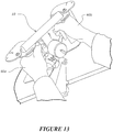
- Figures 13-15 show views of hands 60a, 60b using the rehabilitation device 10 by way of example. As shown, the user's hands 60a, 60b grip a respective handlebar with their palms and thumb, and their fingers grip the finger grip member associated with the handlebar member. Figure 15 also shows the user operating or interacting with a knob or switch 70 mounted to the central upright frame member 22, which may generate signals to enable interaction with a gaming system for example.
- a knob or switch 70 mounted to the central upright frame member 22, which may generate signals to enable interaction with a gaming system for example.
- the bilateral hand rehabilitation device 10 further comprises one or more movement or rotation or position sensors, load sensors, and/or switches that are configured to sense interaction with the bilateral hand rehabilitation device by a user.
- the output signals of such sensors and switches may be used to interact with a gaming system as described next.
- position or rotation sensors are provided on various pivot axes of the rehabilitation device 10.
- a position or rotation sensor 80a-80c for example a rotary encoder, is provided on each of the pivot axes associated with the mounting assembly for sensing tilt or pivoting of the device in the side-to-side and fore-aft directions or planes, and on the pivotal connection associated with the central gear connector 40 to provide an indication as to the position of the finger grip members relative to their respective handlebar members, i.e. where they are along the movement or pivot pathway between the grasp and release positions.
- movement sensors may alternatively or additionally be used at the same or different locations on the device including, but not limited to, rotation sensors in the form of potentiometers, inertial sensors such as gyroscopes and accelerometers, magnetometers, or the like.
- the rehabilitation device may also comprise one or more actuatable switches or dials or buttons or knobs that may be operated to generate switch signals.
- switches may be configured for direct actuation by the fingers or hands of the user, such as the knob 80 shown in Figure 1 and 15 , or could be integrated switches, such as micro-switches, that are configured for indirect actuation by components of the rehabilitation device during particular movements or operation of the device by a user.
- the rehabilitation device may also comprise one or more load or force sensors for sensing force or load occurring in the rehabilitation device during use.
- Figure 16 shows an embodiment of the rehabilitation device in which load sensors 90a, 90b are provided in the central connecting gear or linkage 40 and the crossbar member 20.
- the load sensors or cells generate force signals that can be processed over time and exercise sessions to determine if the unaffected hand is assisting the stroke-affected hand, or otherwise compare the strength of each hand to determine if the affected-paralyzed hand is assisting or resisting motion (e.g. finger grasp or release motion) and whether recovery is taking place as shown by reduction in the assistance from the unaffected hand, for example.
- assisting or resisting motion e.g. finger grasp or release motion
- the bilateral hand rehabilitation device 10 can be operatively connected to an interactive gaming system and the output signals from the one or more sensors and/or switches are processed to enable the user to interact with the gaming system via moving and manipulating the bilateral hand rehabilitation device, including operating switches either directly or via particular movements of the rehabilitation device.
- the rehabilitation device 10 may be operatively connected to an interactive gaming system (e.g. a computer, smart television, gaming console, or any other programmable device or system with an associated display) over a wired or wireless data link or communication link.
- the sensor or switch signals may be pre-processed and sent to an API of the gaming system, or raw sensor signals may be sent to the gaming system and processed into signals to enable interaction with the game presented on the display.
- the games presented may require the user to carry out specific movements or sequences of the finger grasp and release movements, and/or tilting of the device side-to-side and fore-aft to maneuver or control on-screen icons or graphics or characters or otherwise interact with a game.
- the rehabilitation device acts as a control device or input device to the gaming system to enable user interaction, in much the same way as a joy stick, game controller, or other input devices such as keyboard and mouse.
- the motion and interaction with the rehabilitation device 10 can control an on-screen cursor or pointer for example, with switch actuation being used to function as generate 'mouse' clicks.
- the use of the rehabilitation device 10 with a gaming system 100 encourages long-term use of the device and further challenges the user to assist their recovery.
Landscapes
- Health & Medical Sciences (AREA)
- Orthopedic Medicine & Surgery (AREA)
- General Health & Medical Sciences (AREA)
- Physical Education & Sports Medicine (AREA)
- Engineering & Computer Science (AREA)
- Multimedia (AREA)
- Life Sciences & Earth Sciences (AREA)
- Biophysics (AREA)
- Human Computer Interaction (AREA)
- Rehabilitation Tools (AREA)
Description
- This invention relates to a rehabilitation device and system for hands.
- A patient with hemiparesis is typically able to move one arm in a normal manner, but the other arm on the opposite side of their body is at least partially paralysed. In simple terms, the paralysis of the arm is caused by damage to the brain in areas that control the arm or that side of the body. Physically, there is actually nothing actually wrong with the paralysed limb. Neuroplastic recovery from brain injury and the rehabilitation of an affected arm by bilateral relearning and cortical remodeling is well known. Briefly, this involves retraining undamaged parts of the brain, which previously carried out different functions from controlling limbs, to control the paralysed limbs. Neuroplasticity is the fundamental issue that supports the scientific basis for treatment of acquired brain injury with goal-directed experiential therapeutic programs in the context of rehabilitation approaches to the functional consequences of the injury.
- Rehabilitation of the hands is a very challenging operation because of the large number of movements a hand can make and the complex positioning of the end of the arm.
- A hand grip strengthening and competition apparatus is disclosed in
US patent no. 7438669 . The apparatus is provided with a pair of levers mounted to an elongate body for pivotal movement between an open and closed position. An elongate, substantially non-stretchable connector is attached to each lever and prevents the pair of levers from concurrently assuming their respective closed positions. -
US patent no. 3653659 andUS patent no. 2643123 each disclose an exercising device for exercising the grip and the muscles of the forearm having two connected bars, one which is pivotable with respect to the other. -
US patent application no. 2009/0191967 discloses a game apparatus which incorporates a tilt sensor and a motocross or motorcycle style left and right grip as input. - In this specification where reference has been made to patent specifications, other external documents, or other sources of information, this is generally for the purpose of providing a context for discussing the features of the invention. Unless specifically stated otherwise, reference to such external documents is not to be construed as an admission that such documents, or such sources of information, in any jurisdiction, are prior art, or form part of the common general knowledge in the art.
- It is an object of the invention to provide a bilateral hand rehabilitation device and system to assist in wrist and/or hand and/or fingers and/or arm rehabilitation, or to at least provide the public with a useful choice.
- In a first aspect, the invention relates to a bilateral hand rehabilitation device as claimed in claim 1.
- In an embodiment, the handlebar members are spaced-apart from one another and are separate members. In another embodiment, the handlebar members may be portions or parts of a common member or integral with each other.
- In an embodiment, the handlebar members have longitudinal axes that are parallel to each other. In an embodiment, the handlebar members are vertical or upright members. In alternative embodiments, the handlebar members need not be parallel to each other, but may have longitudinal axes that extend at an angle either toward or away from one another, or may have longitudinal axes that are co-axial such that they are aligned in a common axis, e.g. horizontally-orientated handlebars.
- In an embodiment, the pair of handlebar members are provided on or mounted to a common base. By way of example, the base may be substantially planar and the handlebars may extend vertically upward from the planar base. Optionally, a horizontal upper crossbar member may extend between the upper ends of the handlebar members.
- In an embodiment, the finger grip members are pivotally mounted for pivotal or arced movement toward and away from their respective handlebar members. In an embodiment, the path or range of pivotal movement is restricted between a closed or grasp position at or toward the handlebar member, and an open or release position displaced away from the handlebar member.
- In an embodiment, the pivot axis of each finger grip member is offset relative to the longitudinal axis of its respective handlebar member. For example, the pivot axis of the finger grip member may be offset into substantial alignment with the knuckles of hands of a user of the device.
- In an embodiment, the handlebar members are provided in a handlebar assembly that comprises the base, handlebar members and the upper crossbar member.
- In an embodiment, the finger grip members further comprise upper and lower transverse connecting plates that are coupled to the upper and lower ends of each respective finger grip member to provide respective finger grip assemblies. In an embodiment, the finger grip assemblies are pivotally mounted adjacent or relative to their respective handlebar members on opposite sides of the handlebar assembly via pivotal connections or couplings between the upper and lower connecting plates of each finger grip assembly and respective upper and lower portions of the handlebar assembly.
- In an embodiment, the handlebar members are configured to engage the palm and/or thumb of the hands of a user.
- In an embodiment, the finger grip members are configured to engage or be gripped by the inner finger surfaces of the hands of a user.
- In an embodiment, each finger grip assembly further comprises a vertical release member that extends between the upper and lower connecting plates and which is offset from the finger grip member. By way of example, the release member is configured to engage or face the outer or dorsal finger surfaces of the hands of a user when in use. In one configuration, the position and orientation of the release member relative to the finger grip member may be adjusted. In an embodiment, the longitudinal axis of the release members are parallel to the finger grip members and handlebar members.
- In an embodiment, the handlebar members, finger grip members, and asymmetric connection mechanism are parts of a hand grip assembly, and the hand grip assembly is pivotally mounted to a mounting assembly. In one configuration, the mounting assembly provides the hand grip assembly with at least one degree of pivotal movement, but preferably two or more degrees of pivotal movement.
- In an embodiment, the mounting assembly enables the hand grip assembly to rotate relative to at least one pivot axis defined by the mounting assembly. In one configuration, the hand grip assembly is pivotal relative to two orthogonal pivot axes provided by the mounting assembly. In an embodiment, the two pivot axes are spaced-apart.
- In an embodiment, the mounting assembly provides a first pivot axis extending in the bisecting plane between the handlebar members of the handlebar assembly, to enable the hand grip assembly to be tilted from side to side (i.e. rotated either clockwise or anti-clockwise about the first pivot axis), and a second pivot axis that is a transverse orientation relative to the first pivot axis and which allows the hand grip assembly to pivot back and forth (i.e. rotate clockwise or anti-clockwise about the second transverse pivot axis). In this configuration, the first pivot axis extends in a plane that corresponds to the sagittal plane of the user of the device, and the second pivot axis extends in a plane parallel to the coronal plane of the user of the device.
- In an embodiment, the mounting assembly comprises a base that is releasably securable to a support surface or structure, such as a table or other horizontal support surface or similar. In one configuration the base comprises one or more clamping mechanisms to secure the base to the support surface or structure.
- In an embodiment, the mounting assembly further comprises a link member having two ends, the link member being pivotally coupled to the base at or toward one end, and pivotally coupled to the hand grip assembly at or toward the other end. In one configuration, the pivot axes defined by the pivotal couplings or connections at the first and second ends of the link member are transverse to each other to provide the first and second transverse pivot axes of the mounting assembly.
- In an embodiment, the bilateral hand rehabilitation device further comprises one or more movement or rotation or position sensors, load sensors, and/or switches that are configured to sense interaction with the bilateral hand rehabilitation device by a user. In an embodiment, the bilateral hand rehabilitation device is operatively connected to an interactive gaming system and the output signals from the one or more sensors and/or switches are processed to enable the user to interact with the gaming system via moving and manipulating the bilateral hand rehabilitation device, including operating switches either directly or via particular movements of the rehabilitation device.
- In a second aspect, the invention relates to a bilateral hand rehabilitation system as claimed in claim 15.
- The second aspect of the invention may have any one or more of the features mentioned in respect of the first aspect of the invention.
- The term 'comprising' as used in this specification and claims means 'consisting at least in part of. When interpreting each statement in this specification and claims that includes the term 'comprising', features other than that or those prefaced by the term may also be present. Related terms such as 'comprise' and 'comprises' are to be interpreted in the same manner.
- It is intended that reference to a range of numbers disclosed herein (for example, 1 to 10) also incorporates reference to all rational numbers within that range (for example, 1, 1.1, 2, 3, 3.9, 4, 5, 6, 6.5, 7, 8, 9 and 10) and also any range of rational numbers within that range (for example, 2 to 8, 1.5 to 5.5 and 3.1 to 4.7) and, therefore, all sub-ranges of all ranges expressly disclosed herein are hereby expressly disclosed. These are only examples of what is specifically intended and all possible combinations of numerical values between the lowest value and the highest value enumerated are to be considered to be expressly stated in this application in a similar manner.
- As used herein the term 'and/or' means 'and' or 'or', or both.
- As used herein '(s)' following a noun means the plural and/or singular forms of the noun.
- The invention consists in the foregoing and also envisages constructions of which the following gives examples only.
- Preferred embodiments of the invention will be described by way of example only and with reference to the drawings, in which:
-
Figure 1 is a front perspective view of an embodiment of the bilateral hand rehabilitation device in a rest state; -
Figure 2 shows a rear perspective view of the bilateral hand rehabilitation device ofFigure 1 ; -
Figures 3 and 4 show rear and front elevation views respectively of a hand grip assembly of the bilateral hand rehabilitation device ofFigure 1 ; -
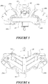
Figures 5 and 6 show top plan and underside views respectively of the hand grip assembly ofFigures 3 and 4 ; -
Figures 7 and 8 show upper front and rear views respectively of the hand grip assembly ofFigures 3 and 4 ; -
Figure 9 shows an underside view of the hand grip assembly ofFigures 3 and 4 but with the handlebar sub-assembly omitted from view; -
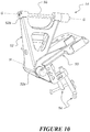
Figure 10 shows an upper front perspective view of a mounting assembly of the bilateral hand rehabilitation device in accordance with an embodiment; -
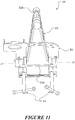
Figure 11 shows a rear elevation view of the mounting assembly ofFigure 10 ; -
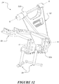
Figure 12 shows a lower rear perspective view of the mounting assembly ofFigure 10 ; -
Figures 13-15 show various views of the bilateral hand rehabilitation device being used and gripped by the hands of a user; -
Figure 16 shows another embodiment of the bilateral hand rehabilitation device having a load sensor or sensors; and -
Figure 17 shows a schematic view of a bilateral hand rehabilitation system comprising the bilateral hand rehabilitation device ofFigure 1 operatively coupled to an interactive gaming system. - The invention relates to a bilateral hand rehabilitation device and system. The rehabilitation device is particularly suited to a person with partial paralysis of an arm and enables a person to exercise the paralysed wrist, hand and/or fingers of an affected arm in a device which is powered by the unaffected wrist, hand and/or fingers of the other unaffected arm. This is particularly useful for a stroke victim suffering hemiplegia, which is when one side of the body is partially paralysed.
- The bilateral hand rehabilitation device is primarily configured to exercise a user's finger grasp and release movements, and is provided with an asymmetric design in which a grasp or release movement performed by one hand causes a simultaneous opposite release or grasp movement of the other hand, i.e. a grasp movement performed by one hand causes a release movement in the other hand and vice versa. This asymmetric configuration enables the strength of the user's grasp in the unaffected hand to effectively power the release movements of the other partially affected hand. Following stroke, a flexion pattern often dominates (fingers tend to be clenched) and the release of the individuals stroke-affected hand grasp is difficult for many stroke survivors to achieve or even to exercise in practice. The hand rehabilitation device enables users to carry out repetitive movement patterns of finger grasp and release with their stroke-affected hand to assist in recovering from the stroke or other neurological injury or disease via the mechanism of neuroplasticity. Hemiplegia often results in contracture of a stroke survivors hand grip so that the hand tends to naturally relax into a grasp position. Grasp is usually strong relative to release and hence grasp of the unaffected hand is used to release the contracture of the affected hand.
- Optionally, in addition to the finger grasp and release movements, the hand rehabilitation device also provides at least one other degree of freedom of movement of the wrist and/or user's upper arms via tilt or rotation of the device with respect to at least one or more pivot axes. For example, in one configuration, the hand rehabilitation device may allow for pivoting of the device from side to side relative to the user and/or fore-aft movements relative to the user, i.e. tilting or pivoting toward or away from the user.
- In some configurations, the rehabilitation device is provided with one or more movement or position sensors, one or more load sensors and one or more operable switches. The rehabilitation device may be operatively coupled, for example via a hardwired link or over a wireless data link to an interactive gaming system (e.g. computer, smart television, gaming console or any other programmable device with an associated display) such that the use and manipulation of the hand rehabilitation device (e.g. finger grasp and release movements, tilting movements side-to-side or fore-aft, and/or direct or indirect switch actuation) can be sensed and used as input to the interactive gaming system to enable the user to interact with a presented game using the rehabilitation device as the input device. The output signals of the movement or position sensors, load sensors and/or actuated switches may be processed by the gaming system or pre-processed and input to an API of the gaming system to enable the user to interact with the displayed game presented by the gaming system.
- Referring to
Figures 1-15 , an example embodiment of the bilateralhand rehabilitation device 10 will be described in further detail. - In this embodiment, the
rehabilitation device 10 comprises an upperhand grip assembly 12 that is mounted to a lower mountingassembly 14. Thehand grip assembly 12 is gripped by the left and right hands of a user and provides for the asymmetric finger grasp and release movements. Thelower mounting assembly 14 is provided with one or more pivot axes to enable the hand grip assembly to pivot or rotate relative to one or more pivot axes such that the hand grip assembly is mounted to the mountingassembly 14 with at least one degree of freedom of rotation or tilt movement. - In this embodiment, the mounting assembly provides two spaced apart pivot axes that have a transverse or orthogonal orientation relative to each other to provide for side-to-side tilt or pivotal movements and fore-aft tilt or pivotal movements of the supported
hand grip assembly 12. The mountingassembly 14 is configured to be secured to a support surface device or structure, including but not limited to a table or similar. In this embodiment, the mounting assembly is configured to be releasably securable to a support structure such as a table, but alternatively the mounting structure could be permanently mounted to another support structure or surface such as a wall or table or similar. - Each of the
hand grip assembly 12 and mountingassembly 14 will be described in further detail below. The various components of the rehabilitation device, such as the hand grip assembly and mounting assembly may be formed of any suitable material or materials, such as plastic or metal for example. The various components of the sub-assemblies may be separately formed and then connected to form the sub-assembly or alternatively the sub-assemblies may be formed as integral parts. - In this embodiment, the
hand grip assembly 12 comprises a pair of left and right spaced aparthandlebar members Figures 1-4 . Thehandlebar members handlebar members - In this embodiment, the handlebar members are fixed or yoked relative to each other in a handlebar sub-assembly. In this embodiment, the handlebar sub-assembly comprises a base component or frame 18 from which each of the
upright handlebar members upper crossbar member 20 that extends between the upper ends of thehandlebar members - In this embodiment, the handlebar sub-assembly may further comprise a central
upright frame member 22 that extends between thebase frame 18 and upper cross-member midway between thehandlebar members upright frame member 22 may mount one or more switches or operable dials or knobs with which the user may interact during use of the device for example. These switches, dials or knobs may generate one or more representative signals, which may be used to interact with a gaming system, as will be further described below. - In this embodiment, the
handlebar members handlebar members - In this embodiment, the
hand grip assembly 12 further comprises a pair offinger grip members respective handlebar member finger grip members finger grip members - In this embodiment, each finger grip member is provided in a finger grip sub-assembly. In this embodiment, each finger grip sub-assembly comprises a
lower plate upper place finger grip members finger grip members respective handlebar member finger grip members respective handlebar members - In this embodiment, each of the finger grip sub-assemblies is pivotally mounted adjacent to its
respective handlebar member upper plate handlebar member lower plate base 18 of the handlebar sub-assembly. - As can be seen in
Figures 1-4 , the upper and lower pivotal connections of each finger grip sub-assembly adjacent to its associatedhandlebar member finger grip members respective handlebar members - Optionally, each finger grip sub-assembly may further have an
elongate release member release members respective handlebar member finger grip member - In this embodiment, the
release members lower adjustment mechanisms Figure 3 ). - As previously discussed, the hand grip assembly is configured such that each
finger grip member respective handlebar member - In this embodiment, the hand grip assembly is configured such that that moveable
finger grip members - In this embodiment, the finger grip sub-assemblies are operatively coupled by an asymmetric connection mechanism. In this embodiment, the asymmetric connection mechanism is provided in the form of gearing or gears. Referring to
Figures 2 and5-9 , the asymmetric connection mechanism comprises a central connectinggear 40 situated between the pair of finger grip sub-assemblies or handlebar members. The connectinggear 40 is substantially planar and pivotally mounted to thebase 18 of the handlebar assembly viapivotal connection 42. Geared ortoothed surfaces gear 40 and these are configured to mesh with corresponding or complementary toothed or geared formation ofsurfaces lower plates finger grip member 24a is pivoted in direction E into the closed or grasp position, the central connectinggear 40 pivots and drives the otherfinger grip member 24b in direction D into the open or release position, and vice versa (seeFigures 8 and9 ). - It will be appreciated that any other suitable asymmetric connection mechanism to create this seesaw-like reciprocating motion between the finger grip members may be used.
- As previously discussed, in this embodiment the
rehabilitation device 10 comprises thehand grip assembly 12 that is pivotally mounted to a mountingassembly 14, which provides additional degrees of freedom of movement of therehabilitation device 10 to assist in exercising of the user's wrists and/or arms and shoulders in combination with finger grasp and release exercise movements provided by thehand grip assembly 12. Referring toFigures 1 and10-12 , in this embodiment the mounting assembly enables thehand grip assembly 12 to rotate relative to at least one pivot axis. In the embodiment shown, the mounting assembly provides two orthogonal or transverse pivot axes about which the hand grip assembly may rotate, tilt or pivot. - In this embodiment, the mounting assembly comprises a base 50 that is configured to be releasably securable or mountable to a support surface or structure such as a table or similar via securing a mounting assembly such as screw clamps 54 or similar as shown. In alternative embodiments, it will be appreciated that the mounting assembly could be configured for permanent or semi-permanent mounting to a wall structure or other support structure if desired.
- In this embodiment, the mounting
assembly 14 further comprises a link member generally indicated at 52, which extends between a first 52a and asecond end 52b. Thefirst end 52a of thelink member 52 is pivotally coupled to the base 50 such that the link member can rotate about a pivot axis HH relative to thebase 50. Thehand grip assembly 12 is pivotally mounted to thesecond end 52b of thelink member 52 such that thehand grip assembly 12 can rotate relative to the link member about a pivot axis GG. The pivotal connection or coupling between the base 50 and lowerfirst end 52a of thelink member 52, and the pivotal connection or coupling between thehand grip assembly 12 and uppersecond end 52b of thelink member 52 may be provided by pivot or rotation shafts that extend through complementary cylindrical bores or similar provided in the components as shown. For example,Figure 10 shows therotation shaft 56 associated with the upper pivot axis GG of the mounting assembly by way of example. - In this embodiment, the two rotational or pivot axes GG and HH are orthogonal or transverse relative to each other, and spaced apart. This provides the
hand grip assembly 12 with two degrees of freedom of rotation. In this embodiment, the first pivot axis GG extends in the bisecting plane between thehandlebar members - In other alternative embodiments, the mounting assembly may only have one degree of freedom of movement or only one pivot axis, or multiple pivot axes to provide multiple degrees of freedom of movement. It will also be appreciated that in an another alternative embodiment, the mounting assembly may not have any pivot axes and may be a fixed structure for mounting the hand grip assembly
-
Figures 13-15 show views ofhands rehabilitation device 10 by way of example. As shown, the user'shands Figure 15 also shows the user operating or interacting with a knob or switch 70 mounted to the centralupright frame member 22, which may generate signals to enable interaction with a gaming system for example. - In this embodiment, the bilateral
hand rehabilitation device 10 further comprises one or more movement or rotation or position sensors, load sensors, and/or switches that are configured to sense interaction with the bilateral hand rehabilitation device by a user. The output signals of such sensors and switches may be used to interact with a gaming system as described next. - By way of example, in this embodiment, position or rotation sensors are provided on various pivot axes of the
rehabilitation device 10. Referring toFigure 2 , a position orrotation sensor 80a-80c, for example a rotary encoder, is provided on each of the pivot axes associated with the mounting assembly for sensing tilt or pivoting of the device in the side-to-side and fore-aft directions or planes, and on the pivotal connection associated with thecentral gear connector 40 to provide an indication as to the position of the finger grip members relative to their respective handlebar members, i.e. where they are along the movement or pivot pathway between the grasp and release positions. It will be appreciated that other types or forms of movement sensors may alternatively or additionally be used at the same or different locations on the device including, but not limited to, rotation sensors in the form of potentiometers, inertial sensors such as gyroscopes and accelerometers, magnetometers, or the like. - The rehabilitation device may also comprise one or more actuatable switches or dials or buttons or knobs that may be operated to generate switch signals. Such switches may be configured for direct actuation by the fingers or hands of the user, such as the
knob 80 shown inFigure 1 and15 , or could be integrated switches, such as micro-switches, that are configured for indirect actuation by components of the rehabilitation device during particular movements or operation of the device by a user. - The rehabilitation device may also comprise one or more load or force sensors for sensing force or load occurring in the rehabilitation device during use. By way of example only,
Figure 16 shows an embodiment of the rehabilitation device in whichload sensors linkage 40 and thecrossbar member 20. In this configuration, the load sensors or cells generate force signals that can be processed over time and exercise sessions to determine if the unaffected hand is assisting the stroke-affected hand, or otherwise compare the strength of each hand to determine if the affected-paralyzed hand is assisting or resisting motion (e.g. finger grasp or release motion) and whether recovery is taking place as shown by reduction in the assistance from the unaffected hand, for example. - In an embodiment, the bilateral
hand rehabilitation device 10 can be operatively connected to an interactive gaming system and the output signals from the one or more sensors and/or switches are processed to enable the user to interact with the gaming system via moving and manipulating the bilateral hand rehabilitation device, including operating switches either directly or via particular movements of the rehabilitation device. - As shown in
Figure 17 , therehabilitation device 10 may be operatively connected to an interactive gaming system (e.g. a computer, smart television, gaming console, or any other programmable device or system with an associated display) over a wired or wireless data link or communication link. The sensor or switch signals may be pre-processed and sent to an API of the gaming system, or raw sensor signals may be sent to the gaming system and processed into signals to enable interaction with the game presented on the display. By way of example, the games presented may require the user to carry out specific movements or sequences of the finger grasp and release movements, and/or tilting of the device side-to-side and fore-aft to maneuver or control on-screen icons or graphics or characters or otherwise interact with a game. In this configuration, the rehabilitation device acts as a control device or input device to the gaming system to enable user interaction, in much the same way as a joy stick, game controller, or other input devices such as keyboard and mouse. In one example, the motion and interaction with therehabilitation device 10 can control an on-screen cursor or pointer for example, with switch actuation being used to function as generate 'mouse' clicks. - The use of the
rehabilitation device 10 with agaming system 100 encourages long-term use of the device and further challenges the user to assist their recovery. - The foregoing description of the invention includes preferred forms thereof. Modifications may be made thereto without departing from the scope of the invention as defined by the accompanying claims.
Claims (15)
- A bilateral hand rehabilitation device (10) comprising:a pair of left and right handlebar members (16a, 16b) that are fixedly coupled or connected together and each having a longitudinal axis;a pair of moveable left and right finger grip members (24a, 24b), one for each of the handlebar members, each finger grip member being elongate and having a longitudinal axis that is maintained in substantially parallel alignment to the longitudinal axis of its respective handlebar member during movement, and each finger grip member being moveably mounted with respect to its respective handlebar member for movement toward and away from the handlebar member to facilitate a user finger grasp and release movement when in use; andan asymmetric connection mechanism (40) that operatively couples the pair of finger grip members (24a, 24b) to each other for simultaneous asymmetric movement of the finger grip members (24a, 24b) such that the movement of one finger grip member toward or away from its respective handlebar member causes the other finger grip member to move in the opposite direction away or toward its respective handlebar member.
- A bilateral hand rehabilitation device (10) according to claim 1, wherein the bilateral hand rehabilitation device further comprises a handlebar assembly (12), wherein the handlebar assembly (12) comprises a base (18), the pair of handlebar members (16a, 16b) and an upper crossbar member (20).
- A bilateral hand rehabilitation device (10) according to claim 2, wherein the pair of handlebar members (16a, 16b) are provided on or mounted to the base (18); or wherein the base (18) is substantially planar and the handlebars (16a, 16b) extend vertically upward from the base (18); or wherein the upper crossbar member (20) extends horizontally between the upper ends of the pair of handlebar members (16a, 16b).
- A bilateral hand rehabilitation device (10) according to claim 2 or claim 3, wherein the pair of finger grip members (24a, 24b) further comprise upper (28a, 28b) and lower (26a, 26b) transverse connecting plates that are coupled to the upper and lower ends of each respective finger grip member to provide respective finger grip assemblies, and wherein the finger grip assemblies are pivotally mounted adjacent or relative to their respective handlebar members (16a, 16b) on opposite sides of the handlebar assembly via pivotal connections or couplings between the upper and lower connecting plates of each finger grip assembly and respective upper and lower portions of the handlebar assembly.
- A bilateral hand rehabilitation device (10) according to claim 4, wherein each finger grip assembly further comprises a release member (30a, 30b) that extends between the upper (28a, 28b) and lower (26a, 26b) connecting plates and which is offset from the finger grip member (24a, 24b); and wherein each release member (30a, 30b) is configured to engage or face the outer or dorsal finger surfaces of the hands of a user when in use.
- A bilateral hand rehabilitation device (10) according to claim 5, wherein the position and orientation of each release member (30a, 30b) relative to its respective finger grip member (24a, 24b) is adjustable; or wherein the longitudinal axis of the release members (30a, 30b) are parallel to the finger grip members (24a, 24b) and handlebar members (16a, 16b).
- A bilateral hand rehabilitation device (10) according to any one of claims 1-6, wherein the handlebar members (16a, 16b), finger grip members (24a, 24b), and asymmetric connection mechanism (40) are parts of a hand grip assembly (12), and the device further comprises a mounting assembly (14) to which the hand grip assembly (12) is pivotally mounted; and wherein the mounting assembly (14) provides the hand grip assembly with at least one degree of pivotal movement; or wherein the mounting assembly (14) provides the hand grip assembly (12) with at least two degrees of pivotal movement.
- A bilateral hand rehabilitation device (10) according to claim 7, wherein the hand grip assembly (12) is pivotal relative to two orthogonal pivot axes provided by the mounting assembly (14); and wherein the two pivot axes provided by the mounting assembly (14) are spaced-apart.
- A bilateral hand rehabilitation device (10) according to claim 7 or claim 8, wherein the mounting assembly (14) provides a first pivot axis extending in the bisecting plane between the handlebar members (16a, 16b) of the hand grip assembly (12), to enable the hand grip assembly (12) to be tilted from side to side, and a second pivot axis that is a transverse orientation relative to the first pivot axis and which allows the hand grip assembly (12) to pivot back and forth; and wherein the first pivot axis extends in a plane that corresponds to the sagittal plane of the user of the device, and the second pivot axis extends in a plane parallel to the coronal plane of the user of the device.
- A bilateral hand rehabilitation device (10) according to any one of claims 1-9, wherein the finger grip members (24a, 24b) are pivotally mounted for pivotal or arced movement toward and away from their respective handlebar members (16a, 16b); and wherein the path or range of pivotal movement of each finger grip member (24a, 24b) is restricted between a closed or grasp position at or toward its respective handlebar member (16a, 16b), and an open or release position displaced away from its respective handlebar member (16a, 16b).
- A bilateral hand rehabilitation device (10) according to claim 10, wherein the pivot axis of each finger grip member (24a, 24b) is offset relative to the longitudinal axis of its respective handlebar member (16a, 16b); or wherein the pivot axis of each finger grip member (16a, 16b) is offset into substantial alignment with the knuckles of hands of a user of the device.
- A bilateral hand rehabilitation device (10) according to any one of claims 1-11, wherein the handlebar members (16a, 16b) are configured to engage the palm and thumb of the hands of a user; and wherein the finger grip members (24a, 24b) are configured to engage or be gripped by the inner finger surfaces of the hands of a user.
- A bilateral hand rehabilitation device (10) according to any one of claims 1-12, wherein the pair of handlebar members (16a, 16b) have longitudinal axes that are parallel to each other, or wherein the pair of handlebar members (16a, 16b) are vertical or upright members; or wherein the pair of handlebar members (16a, 16b) have longitudinal axes that extend at an angle either toward or away from one another; or wherein the pair of handlebar members (16a, 16b) have longitudinal axes that are co-axial such that they are aligned in a common axis.
- A bilateral hand rehabilitation device (10) according to any one of claims 1-13, further comprising one or more sensors and/or switches that are configured to sense interaction with the bilateral hand rehabilitation device (10) by a user, and wherein the bilateral hand rehabilitation device (10) is operatively connected to an interactive gaming system (100) and output signals from the one or more sensors and/or switches are processed to enable the user to interact with the gaming system (100) via moving and manipulating the bilateral hand rehabilitation device (10) and/or operating the one or more switches.
- A bilateral rehabilitation system comprising:a bilateral hand rehabilitation device (10) according to any one of claims 1-14; andan interactive gaming system (100) that presents an interactive game to the user of the rehabilitation device on a display and processes sensor and/or switch output signals generated in response to user interaction with the rehabilitation device (10) to enable the user to interact with the present game via use of the rehabilitation device (10) as an input or control device for the interactive gaming system (100).
Applications Claiming Priority (2)
| Application Number | Priority Date | Filing Date | Title |
|---|---|---|---|
| NZ71456215 | 2015-11-26 | ||
| PCT/IB2016/057145 WO2017090009A1 (en) | 2015-11-26 | 2016-11-28 | Bilateral hand rehabilitation device and system |
Publications (3)
| Publication Number | Publication Date |
|---|---|
| EP3365081A1 EP3365081A1 (en) | 2018-08-29 |
| EP3365081A4 EP3365081A4 (en) | 2019-04-24 |
| EP3365081B1 true EP3365081B1 (en) | 2020-08-19 |
Family
ID=58763142
Family Applications (1)
| Application Number | Title | Priority Date | Filing Date |
|---|---|---|---|
| EP16868130.2A Active EP3365081B1 (en) | 2015-11-26 | 2016-11-28 | Bilateral hand rehabilitation device and system |
Country Status (6)
| Country | Link |
|---|---|
| US (1) | US10843032B2 (en) |
| EP (1) | EP3365081B1 (en) |
| CN (1) | CN108601971B (en) |
| AU (1) | AU2016358498B2 (en) |
| NZ (1) | NZ742546A (en) |
| WO (1) | WO2017090009A1 (en) |
Families Citing this family (5)
| Publication number | Priority date | Publication date | Assignee | Title |
|---|---|---|---|---|
| CN110269780B (en) * | 2019-07-18 | 2021-04-06 | 河南师范大学新联学院 | Finger joint rehabilitation training mechanism |
| IT201900019469A1 (en) | 2019-10-22 | 2021-04-22 | Euro Lugli | HAND PHYSIOTHERAPY EQUIPMENT |
| CN112237721A (en) * | 2020-10-27 | 2021-01-19 | 广东长虹电子有限公司 | TV system, grip strength device and TV set with grip strength detection function |
| CN112826702A (en) * | 2021-01-04 | 2021-05-25 | 中国人民解放军北部战区总医院 | A kind of auxiliary rehabilitation device after cardiovascular surgery |
| US11911651B1 (en) | 2023-08-10 | 2024-02-27 | Barron Associates, Inc. | System, device and method for electronically mediated upper extremity therapy |
Family Cites Families (18)
| Publication number | Priority date | Publication date | Assignee | Title |
|---|---|---|---|---|
| US2643123A (en) * | 1949-08-24 | 1953-06-23 | Spinks Joseph Milton | Grip type exercising device |
| US3653659A (en) * | 1970-08-20 | 1972-04-04 | Whittaker Corp | Wrist exerciser device |
| US5484355A (en) * | 1993-10-01 | 1996-01-16 | Smith & Nephew Roylan, Inc. | System for therapeutic exercise and evaluation |
| US5529550A (en) | 1995-02-17 | 1996-06-25 | Gripstrength Inc | Device for forearm, elbow, wrist, hand, finger and thumb exercise |
| US5698782A (en) * | 1997-01-09 | 1997-12-16 | Ministry Of Solicitor General And Correctional Services | Hand and arm strength testing apparatus to be used in a constable selection process |
| US6149612A (en) | 1998-09-14 | 2000-11-21 | Schnapp; Moacir | Rehabilitative apparatus for treating reflex sympathetic dystrophy |
| CN100386063C (en) | 2004-08-20 | 2008-05-07 | 清华大学 | Handle for rehabilitation training of flexion and extension of fingers and wrists |
| WO2006088221A1 (en) * | 2005-02-17 | 2006-08-24 | Ssd Company Limited | Game apparatus and controller |
| US7438669B1 (en) * | 2006-01-10 | 2008-10-21 | Bloom Lawrence E | Hand grip strengthening and competition apparatus |
| US20070265148A1 (en) | 2006-05-15 | 2007-11-15 | Richard Lin | Pneumatic-aided fitness equipment |
| AU2014202518A1 (en) | 2007-11-30 | 2014-05-29 | Auckland Uniservices Limited | Training device |
| JP2010201111A (en) | 2009-03-06 | 2010-09-16 | Akita Prefecture | Upper limb rehabilitation support device |
| CA2775086C (en) | 2009-09-22 | 2017-10-24 | Mount Sinai School Of Medicine | Rehabilitative training devices for use by stroke patients |
| RU2447919C2 (en) * | 2010-03-03 | 2012-04-20 | Надежда Николаевна Потапова | Multipurpose hand expander-massager "avan-achaky" |
| JP3173845U (en) | 2011-12-12 | 2012-02-23 | 喜国 田附 | Rehabilitation equipment |
| CN202802633U (en) * | 2012-09-24 | 2013-03-20 | 谯霁昭 | Multifunctional fitness device |
| KR101501527B1 (en) | 2013-09-12 | 2015-03-11 | 재단법인대구경북과학기술원 | Upper limb rehabilitation training device |
| CN203591423U (en) * | 2013-12-13 | 2014-05-14 | 霍橡楠 | Training device for coordination exercise of two hands |
-
2016
- 2016-11-28 CN CN201680078532.4A patent/CN108601971B/en active Active
- 2016-11-28 NZ NZ742546A patent/NZ742546A/en unknown
- 2016-11-28 AU AU2016358498A patent/AU2016358498B2/en active Active
- 2016-11-28 US US15/778,598 patent/US10843032B2/en active Active
- 2016-11-28 WO PCT/IB2016/057145 patent/WO2017090009A1/en not_active Ceased
- 2016-11-28 EP EP16868130.2A patent/EP3365081B1/en active Active
Non-Patent Citations (1)
| Title |
|---|
| None * |
Also Published As
| Publication number | Publication date |
|---|---|
| EP3365081A4 (en) | 2019-04-24 |
| WO2017090009A1 (en) | 2017-06-01 |
| EP3365081A1 (en) | 2018-08-29 |
| AU2016358498A1 (en) | 2018-06-07 |
| NZ742546A (en) | 2022-08-26 |
| AU2016358498B2 (en) | 2021-02-18 |
| CN108601971B (en) | 2020-06-12 |
| US20190269962A1 (en) | 2019-09-05 |
| US10843032B2 (en) | 2020-11-24 |
| CN108601971A (en) | 2018-09-28 |
Similar Documents
| Publication | Publication Date | Title |
|---|---|---|
| AU2016358498B2 (en) | Bilateral hand rehabilitation device and system | |
| JP6151693B2 (en) | Control mechanism that can be operated by mechanical multi-axis handle | |
| CN102933269B (en) | Exercise system and controller | |
| CN105943308B (en) | A kind of hand exoskeleton device for rehabilitation training | |
| GB2523043B (en) | Arm exercise device and system | |
| JP6656151B2 (en) | Rehabilitation support device and control program for rehabilitation support device | |
| Ates et al. | Combined active wrist and hand orthosis for home use: Lessons learned | |
| CN107865751A (en) | Devices to restore upper and lower extremity movement | |
| JP2015529519A (en) | Interface between user and laparoscopic instrument | |
| KR102000484B1 (en) | Upper limb rehabilitation device and controlling method for the same | |
| KR102096292B1 (en) | Upper limb rehabilitation device with curved handgrip | |
| KR101501527B1 (en) | Upper limb rehabilitation training device | |
| CN206121040U (en) | Recovered training device of upper limbs and virtual reality training system thereof | |
| KR20190008585A (en) | Active training system for rehabilitating fingers and wrist using display device | |
| Macovei et al. | A short overview of upper limb rehabilitation devices | |
| KR101384305B1 (en) | Upper Limb Motion Providing Haptic Device and Method | |
| JP2018522631A (en) | Mouse-type rehabilitation training device | |
| JP6957036B2 (en) | Position / force control device | |
| Almusawi | Design and Development of a New Hand and Wrist Rehabilitation Robot-Assisted System; Equipped With Game-Based Therapy, ROM and Tip-Pinch Force Self-Assessment Approaches | |
| Pasaribu et al. | DESIGN AND DEVELOPMENT OF A LOW-COST SOFT-ROBOTIC ACTUATOR SYSTEM FOR HAND REHABILITATION: THE E‑GLOVE PROTOTYPE | |
| CN119562844A (en) | Sensory-Motor Hand Therapy Device | |
| PL246508B1 (en) | Hand rehabilitation device | |
| JP2011167411A (en) | Training device | |
| JP2007331089A (en) | Robot manipulating system | |
| NZ603451B2 (en) | Arm exercise device and system |
Legal Events
| Date | Code | Title | Description |
|---|---|---|---|
| STAA | Information on the status of an ep patent application or granted ep patent |
Free format text: STATUS: THE INTERNATIONAL PUBLICATION HAS BEEN MADE |
|
| PUAI | Public reference made under article 153(3) epc to a published international application that has entered the european phase |
Free format text: ORIGINAL CODE: 0009012 |
|
| STAA | Information on the status of an ep patent application or granted ep patent |
Free format text: STATUS: REQUEST FOR EXAMINATION WAS MADE |
|
| 17P | Request for examination filed |
Effective date: 20180516 |
|
| AK | Designated contracting states |
Kind code of ref document: A1 Designated state(s): AL AT BE BG CH CY CZ DE DK EE ES FI FR GB GR HR HU IE IS IT LI LT LU LV MC MK MT NL NO PL PT RO RS SE SI SK SM TR |
|
| AX | Request for extension of the european patent |
Extension state: BA ME |
|
| DAV | Request for validation of the european patent (deleted) | ||
| DAX | Request for extension of the european patent (deleted) | ||
| A4 | Supplementary search report drawn up and despatched |
Effective date: 20190322 |
|
| RIC1 | Information provided on ipc code assigned before grant |
Ipc: A63B 23/16 20060101AFI20190318BHEP Ipc: A63B 23/035 20060101ALN20190318BHEP Ipc: A63B 21/00 20060101ALI20190318BHEP Ipc: A63B 71/06 20060101ALN20190318BHEP Ipc: A63F 13/24 20140101ALI20190318BHEP Ipc: A63B 71/00 20060101ALN20190318BHEP Ipc: A63B 21/16 20060101ALN20190318BHEP Ipc: A61H 1/02 20060101ALI20190318BHEP |
|
| GRAP | Despatch of communication of intention to grant a patent |
Free format text: ORIGINAL CODE: EPIDOSNIGR1 |
|
| STAA | Information on the status of an ep patent application or granted ep patent |
Free format text: STATUS: GRANT OF PATENT IS INTENDED |
|
| RIC1 | Information provided on ipc code assigned before grant |
Ipc: A63F 13/24 20140101ALI20200127BHEP Ipc: A63B 21/16 20060101ALN20200127BHEP Ipc: A61H 1/02 20060101ALI20200127BHEP Ipc: A63B 21/00 20060101ALI20200127BHEP Ipc: A63B 23/16 20060101AFI20200127BHEP Ipc: A63B 71/06 20060101ALN20200127BHEP Ipc: A63B 23/035 20060101ALN20200127BHEP Ipc: A63B 71/00 20060101ALN20200127BHEP |
|
| INTG | Intention to grant announced |
Effective date: 20200302 |
|
| GRAJ | Information related to disapproval of communication of intention to grant by the applicant or resumption of examination proceedings by the epo deleted |
Free format text: ORIGINAL CODE: EPIDOSDIGR1 |
|
| STAA | Information on the status of an ep patent application or granted ep patent |
Free format text: STATUS: REQUEST FOR EXAMINATION WAS MADE |
|
| GRAR | Information related to intention to grant a patent recorded |
Free format text: ORIGINAL CODE: EPIDOSNIGR71 |
|
| GRAS | Grant fee paid |
Free format text: ORIGINAL CODE: EPIDOSNIGR3 |
|
| STAA | Information on the status of an ep patent application or granted ep patent |
Free format text: STATUS: GRANT OF PATENT IS INTENDED |
|
| GRAA | (expected) grant |
Free format text: ORIGINAL CODE: 0009210 |
|
| STAA | Information on the status of an ep patent application or granted ep patent |
Free format text: STATUS: THE PATENT HAS BEEN GRANTED |
|
| INTC | Intention to grant announced (deleted) | ||
| RIC1 | Information provided on ipc code assigned before grant |
Ipc: A61H 1/02 20060101ALI20200629BHEP Ipc: A63B 21/00 20060101ALI20200629BHEP Ipc: A63B 71/06 20060101ALN20200629BHEP Ipc: A63F 13/24 20140101ALI20200629BHEP Ipc: A63B 23/16 20060101AFI20200629BHEP Ipc: A63B 23/035 20060101ALN20200629BHEP Ipc: A63B 71/00 20060101ALN20200629BHEP Ipc: A63B 21/16 20060101ALN20200629BHEP |
|
| AK | Designated contracting states |
Kind code of ref document: B1 Designated state(s): AL AT BE BG CH CY CZ DE DK EE ES FI FR GB GR HR HU IE IS IT LI LT LU LV MC MK MT NL NO PL PT RO RS SE SI SK SM TR |
|
| INTG | Intention to grant announced |
Effective date: 20200710 |
|
| REG | Reference to a national code |
Ref country code: CH Ref legal event code: EP |
|
| REG | Reference to a national code |
Ref country code: DE Ref legal event code: R096 Ref document number: 602016042509 Country of ref document: DE |
|
| REG | Reference to a national code |
Ref country code: AT Ref legal event code: REF Ref document number: 1303283 Country of ref document: AT Kind code of ref document: T Effective date: 20200915 |
|
| REG | Reference to a national code |
Ref country code: IE Ref legal event code: FG4D |
|
| REG | Reference to a national code |
Ref country code: LT Ref legal event code: MG4D |
|
| REG | Reference to a national code |
Ref country code: NL Ref legal event code: MP Effective date: 20200819 |
|
| PG25 | Lapsed in a contracting state [announced via postgrant information from national office to epo] |
Ref country code: LT Free format text: LAPSE BECAUSE OF FAILURE TO SUBMIT A TRANSLATION OF THE DESCRIPTION OR TO PAY THE FEE WITHIN THE PRESCRIBED TIME-LIMIT Effective date: 20200819 Ref country code: HR Free format text: LAPSE BECAUSE OF FAILURE TO SUBMIT A TRANSLATION OF THE DESCRIPTION OR TO PAY THE FEE WITHIN THE PRESCRIBED TIME-LIMIT Effective date: 20200819 Ref country code: PT Free format text: LAPSE BECAUSE OF FAILURE TO SUBMIT A TRANSLATION OF THE DESCRIPTION OR TO PAY THE FEE WITHIN THE PRESCRIBED TIME-LIMIT Effective date: 20201221 Ref country code: FI Free format text: LAPSE BECAUSE OF FAILURE TO SUBMIT A TRANSLATION OF THE DESCRIPTION OR TO PAY THE FEE WITHIN THE PRESCRIBED TIME-LIMIT Effective date: 20200819 Ref country code: SE Free format text: LAPSE BECAUSE OF FAILURE TO SUBMIT A TRANSLATION OF THE DESCRIPTION OR TO PAY THE FEE WITHIN THE PRESCRIBED TIME-LIMIT Effective date: 20200819 Ref country code: NO Free format text: LAPSE BECAUSE OF FAILURE TO SUBMIT A TRANSLATION OF THE DESCRIPTION OR TO PAY THE FEE WITHIN THE PRESCRIBED TIME-LIMIT Effective date: 20201119 Ref country code: GR Free format text: LAPSE BECAUSE OF FAILURE TO SUBMIT A TRANSLATION OF THE DESCRIPTION OR TO PAY THE FEE WITHIN THE PRESCRIBED TIME-LIMIT Effective date: 20201120 Ref country code: BG Free format text: LAPSE BECAUSE OF FAILURE TO SUBMIT A TRANSLATION OF THE DESCRIPTION OR TO PAY THE FEE WITHIN THE PRESCRIBED TIME-LIMIT Effective date: 20201119 |
|
| REG | Reference to a national code |
Ref country code: AT Ref legal event code: MK05 Ref document number: 1303283 Country of ref document: AT Kind code of ref document: T Effective date: 20200819 |
|
| REG | Reference to a national code |
Ref country code: GB Ref legal event code: 732E Free format text: REGISTERED BETWEEN 20210121 AND 20210127 Ref country code: DE Ref legal event code: R082 Ref document number: 602016042509 Country of ref document: DE Representative=s name: BOEHMERT & BOEHMERT ANWALTSPARTNERSCHAFT MBB -, DE Ref country code: DE Ref legal event code: R081 Ref document number: 602016042509 Country of ref document: DE Owner name: EXSURGO REHAB LTD., NZ Free format text: FORMER OWNER: CALLAGHAN INNOVATION, LOWER HUTT, NZ |
|
| PG25 | Lapsed in a contracting state [announced via postgrant information from national office to epo] |
Ref country code: NL Free format text: LAPSE BECAUSE OF FAILURE TO SUBMIT A TRANSLATION OF THE DESCRIPTION OR TO PAY THE FEE WITHIN THE PRESCRIBED TIME-LIMIT Effective date: 20200819 Ref country code: RS Free format text: LAPSE BECAUSE OF FAILURE TO SUBMIT A TRANSLATION OF THE DESCRIPTION OR TO PAY THE FEE WITHIN THE PRESCRIBED TIME-LIMIT Effective date: 20200819 Ref country code: LV Free format text: LAPSE BECAUSE OF FAILURE TO SUBMIT A TRANSLATION OF THE DESCRIPTION OR TO PAY THE FEE WITHIN THE PRESCRIBED TIME-LIMIT Effective date: 20200819 Ref country code: PL Free format text: LAPSE BECAUSE OF FAILURE TO SUBMIT A TRANSLATION OF THE DESCRIPTION OR TO PAY THE FEE WITHIN THE PRESCRIBED TIME-LIMIT Effective date: 20200819 Ref country code: IS Free format text: LAPSE BECAUSE OF FAILURE TO SUBMIT A TRANSLATION OF THE DESCRIPTION OR TO PAY THE FEE WITHIN THE PRESCRIBED TIME-LIMIT Effective date: 20201219 |
|
| PG25 | Lapsed in a contracting state [announced via postgrant information from national office to epo] |
Ref country code: EE Free format text: LAPSE BECAUSE OF FAILURE TO SUBMIT A TRANSLATION OF THE DESCRIPTION OR TO PAY THE FEE WITHIN THE PRESCRIBED TIME-LIMIT Effective date: 20200819 Ref country code: SM Free format text: LAPSE BECAUSE OF FAILURE TO SUBMIT A TRANSLATION OF THE DESCRIPTION OR TO PAY THE FEE WITHIN THE PRESCRIBED TIME-LIMIT Effective date: 20200819 Ref country code: RO Free format text: LAPSE BECAUSE OF FAILURE TO SUBMIT A TRANSLATION OF THE DESCRIPTION OR TO PAY THE FEE WITHIN THE PRESCRIBED TIME-LIMIT Effective date: 20200819 Ref country code: CZ Free format text: LAPSE BECAUSE OF FAILURE TO SUBMIT A TRANSLATION OF THE DESCRIPTION OR TO PAY THE FEE WITHIN THE PRESCRIBED TIME-LIMIT Effective date: 20200819 Ref country code: DK Free format text: LAPSE BECAUSE OF FAILURE TO SUBMIT A TRANSLATION OF THE DESCRIPTION OR TO PAY THE FEE WITHIN THE PRESCRIBED TIME-LIMIT Effective date: 20200819 |
|
| REG | Reference to a national code |
Ref country code: DE Ref legal event code: R097 Ref document number: 602016042509 Country of ref document: DE |
|
| PG25 | Lapsed in a contracting state [announced via postgrant information from national office to epo] |
Ref country code: AT Free format text: LAPSE BECAUSE OF FAILURE TO SUBMIT A TRANSLATION OF THE DESCRIPTION OR TO PAY THE FEE WITHIN THE PRESCRIBED TIME-LIMIT Effective date: 20200819 Ref country code: AL Free format text: LAPSE BECAUSE OF FAILURE TO SUBMIT A TRANSLATION OF THE DESCRIPTION OR TO PAY THE FEE WITHIN THE PRESCRIBED TIME-LIMIT Effective date: 20200819 Ref country code: ES Free format text: LAPSE BECAUSE OF FAILURE TO SUBMIT A TRANSLATION OF THE DESCRIPTION OR TO PAY THE FEE WITHIN THE PRESCRIBED TIME-LIMIT Effective date: 20200819 |
|
| PLBE | No opposition filed within time limit |
Free format text: ORIGINAL CODE: 0009261 |
|
| STAA | Information on the status of an ep patent application or granted ep patent |
Free format text: STATUS: NO OPPOSITION FILED WITHIN TIME LIMIT |
|
| PG25 | Lapsed in a contracting state [announced via postgrant information from national office to epo] |
Ref country code: MC Free format text: LAPSE BECAUSE OF FAILURE TO SUBMIT A TRANSLATION OF THE DESCRIPTION OR TO PAY THE FEE WITHIN THE PRESCRIBED TIME-LIMIT Effective date: 20200819 Ref country code: SK Free format text: LAPSE BECAUSE OF FAILURE TO SUBMIT A TRANSLATION OF THE DESCRIPTION OR TO PAY THE FEE WITHIN THE PRESCRIBED TIME-LIMIT Effective date: 20200819 |
|
| REG | Reference to a national code |
Ref country code: CH Ref legal event code: PL |
|
| 26N | No opposition filed |
Effective date: 20210520 |
|
| PG25 | Lapsed in a contracting state [announced via postgrant information from national office to epo] |
Ref country code: IT Free format text: LAPSE BECAUSE OF FAILURE TO SUBMIT A TRANSLATION OF THE DESCRIPTION OR TO PAY THE FEE WITHIN THE PRESCRIBED TIME-LIMIT Effective date: 20200819 Ref country code: LU Free format text: LAPSE BECAUSE OF NON-PAYMENT OF DUE FEES Effective date: 20201128 |
|
| REG | Reference to a national code |
Ref country code: BE Ref legal event code: MM Effective date: 20201130 |
|
| PG25 | Lapsed in a contracting state [announced via postgrant information from national office to epo] |
Ref country code: CH Free format text: LAPSE BECAUSE OF NON-PAYMENT OF DUE FEES Effective date: 20201130 Ref country code: SI Free format text: LAPSE BECAUSE OF FAILURE TO SUBMIT A TRANSLATION OF THE DESCRIPTION OR TO PAY THE FEE WITHIN THE PRESCRIBED TIME-LIMIT Effective date: 20200819 Ref country code: LI Free format text: LAPSE BECAUSE OF NON-PAYMENT OF DUE FEES Effective date: 20201130 |
|
| PG25 | Lapsed in a contracting state [announced via postgrant information from national office to epo] |
Ref country code: IE Free format text: LAPSE BECAUSE OF NON-PAYMENT OF DUE FEES Effective date: 20201128 |
|
| PG25 | Lapsed in a contracting state [announced via postgrant information from national office to epo] |
Ref country code: TR Free format text: LAPSE BECAUSE OF FAILURE TO SUBMIT A TRANSLATION OF THE DESCRIPTION OR TO PAY THE FEE WITHIN THE PRESCRIBED TIME-LIMIT Effective date: 20200819 Ref country code: MT Free format text: LAPSE BECAUSE OF FAILURE TO SUBMIT A TRANSLATION OF THE DESCRIPTION OR TO PAY THE FEE WITHIN THE PRESCRIBED TIME-LIMIT Effective date: 20200819 Ref country code: CY Free format text: LAPSE BECAUSE OF FAILURE TO SUBMIT A TRANSLATION OF THE DESCRIPTION OR TO PAY THE FEE WITHIN THE PRESCRIBED TIME-LIMIT Effective date: 20200819 |
|
| PG25 | Lapsed in a contracting state [announced via postgrant information from national office to epo] |
Ref country code: MK Free format text: LAPSE BECAUSE OF FAILURE TO SUBMIT A TRANSLATION OF THE DESCRIPTION OR TO PAY THE FEE WITHIN THE PRESCRIBED TIME-LIMIT Effective date: 20200819 |
|
| PG25 | Lapsed in a contracting state [announced via postgrant information from national office to epo] |
Ref country code: BE Free format text: LAPSE BECAUSE OF NON-PAYMENT OF DUE FEES Effective date: 20201130 |
|
| PGFP | Annual fee paid to national office [announced via postgrant information from national office to epo] |
Ref country code: DE Payment date: 20250429 Year of fee payment: 9 |
|
| PGFP | Annual fee paid to national office [announced via postgrant information from national office to epo] |
Ref country code: GB Payment date: 20250429 Year of fee payment: 9 |
|
| PGFP | Annual fee paid to national office [announced via postgrant information from national office to epo] |
Ref country code: FR Payment date: 20250429 Year of fee payment: 9 |