EP3365075B1 - Respirator mask with voice transmittal feature - Google Patents
Respirator mask with voice transmittal feature Download PDFInfo
- Publication number
- EP3365075B1 EP3365075B1 EP16858218.7A EP16858218A EP3365075B1 EP 3365075 B1 EP3365075 B1 EP 3365075B1 EP 16858218 A EP16858218 A EP 16858218A EP 3365075 B1 EP3365075 B1 EP 3365075B1
- Authority
- EP
- European Patent Office
- Prior art keywords
- membrane
- mask
- user
- voice transmittal
- frame
- Prior art date
- Legal status (The legal status is an assumption and is not a legal conclusion. Google has not performed a legal analysis and makes no representation as to the accuracy of the status listed.)
- Active
Links
Images



Classifications
-
- A—HUMAN NECESSITIES
- A62—LIFE-SAVING; FIRE-FIGHTING
- A62B—DEVICES, APPARATUS OR METHODS FOR LIFE-SAVING
- A62B18/00—Breathing masks or helmets, e.g. affording protection against chemical agents or for use at high altitudes or incorporating a pump or compressor for reducing the inhalation effort
- A62B18/08—Component parts for gas-masks or gas-helmets, e.g. windows, straps, speech transmitters, signal-devices
-
- A—HUMAN NECESSITIES
- A62—LIFE-SAVING; FIRE-FIGHTING
- A62B—DEVICES, APPARATUS OR METHODS FOR LIFE-SAVING
- A62B18/00—Breathing masks or helmets, e.g. affording protection against chemical agents or for use at high altitudes or incorporating a pump or compressor for reducing the inhalation effort
- A62B18/04—Gas helmets
-
- A—HUMAN NECESSITIES
- A62—LIFE-SAVING; FIRE-FIGHTING
- A62B—DEVICES, APPARATUS OR METHODS FOR LIFE-SAVING
- A62B23/00—Filters for breathing-protection purposes
- A62B23/02—Filters for breathing-protection purposes for respirators
- A62B23/025—Filters for breathing-protection purposes for respirators the filter having substantially the shape of a mask
-
- F—MECHANICAL ENGINEERING; LIGHTING; HEATING; WEAPONS; BLASTING
- F16—ENGINEERING ELEMENTS AND UNITS; GENERAL MEASURES FOR PRODUCING AND MAINTAINING EFFECTIVE FUNCTIONING OF MACHINES OR INSTALLATIONS; THERMAL INSULATION IN GENERAL
- F16J—PISTONS; CYLINDERS; SEALINGS
- F16J3/00—Diaphragms; Bellows; Bellows pistons
- F16J3/02—Diaphragms
-
- H—ELECTRICITY
- H04—ELECTRIC COMMUNICATION TECHNIQUE
- H04R—LOUDSPEAKERS, MICROPHONES, GRAMOPHONE PICK-UPS OR LIKE ACOUSTIC ELECTROMECHANICAL TRANSDUCERS; ELECTRIC HEARING AIDS; PUBLIC ADDRESS SYSTEMS
- H04R1/00—Details of transducers, loudspeakers or microphones
- H04R1/08—Mouthpieces; Microphones; Attachments therefor
-
- A—HUMAN NECESSITIES
- A62—LIFE-SAVING; FIRE-FIGHTING
- A62B—DEVICES, APPARATUS OR METHODS FOR LIFE-SAVING
- A62B18/00—Breathing masks or helmets, e.g. affording protection against chemical agents or for use at high altitudes or incorporating a pump or compressor for reducing the inhalation effort
- A62B18/02—Masks
- A62B18/025—Halfmasks
-
- H—ELECTRICITY
- H04—ELECTRIC COMMUNICATION TECHNIQUE
- H04R—LOUDSPEAKERS, MICROPHONES, GRAMOPHONE PICK-UPS OR LIKE ACOUSTIC ELECTROMECHANICAL TRANSDUCERS; ELECTRIC HEARING AIDS; PUBLIC ADDRESS SYSTEMS
- H04R1/00—Details of transducers, loudspeakers or microphones
- H04R1/02—Casings; Cabinets ; Supports therefor; Mountings therein
- H04R1/028—Casings; Cabinets ; Supports therefor; Mountings therein associated with devices performing functions other than acoustics, e.g. electric candles
-
- H—ELECTRICITY
- H04—ELECTRIC COMMUNICATION TECHNIQUE
- H04R—LOUDSPEAKERS, MICROPHONES, GRAMOPHONE PICK-UPS OR LIKE ACOUSTIC ELECTROMECHANICAL TRANSDUCERS; ELECTRIC HEARING AIDS; PUBLIC ADDRESS SYSTEMS
- H04R2201/00—Details of transducers, loudspeakers or microphones covered by H04R1/00 but not provided for in any of its subgroups
- H04R2201/02—Details casings, cabinets or mounting therein for transducers covered by H04R1/02 but not provided for in any of its subgroups
- H04R2201/023—Transducers incorporated in garment, rucksacks or the like
Definitions
- respirator masks for respiratory protection relate generally to respirator masks for respiratory protection.
- Respirator masks are used in environments where individuals are exposed to hazardous materials, such as gases, vapors, aerosols (such as dusts, mists, and/or biological agents), and/or the like. Respirator masks come in a large variety of types and sizes, ranging from cheaper, disposable masks to higher cost, reusable masks that include replaceable filtration cartridges. Some respirator masks, such as half mask respirators, cover the mouth and nose of the user but do not cover the user's eyes, while other respirator masks, such as full face mask respirators, cover the user's eyes in addition to the user's mouth and nose.
- respirator masks tend to render the speech of the wearer unintelligible, thereby making communication between users difficult. For example, because the respirator mask covers the user's mouth, the body of the respirator mask obstructs the free travel of sound waves from the user's mouth and thereby impairs speech intelligibility. Such speech intelligibility may occur when a user wearing the respirator mask speaks to another person who is not wearing a mask, and/or may occur when two users wearing respirator masks speak with each other. In some circumstances, a user may choose not to wear a respirator mask because of speech intelligibility, which may result in injury to the user's respiratory system.
- the invention advantageously provides a respirator mask that includes a passive voice transmittal feature as defined in claim 1.
- the respirator mask provides respiratory protection while also allowing for the transmission of intelligible speech from a user.
- the respiratory mask includes a body defining an interior space of the mask and including a first surface and a second surface opposite the first surface, the first surface defining the interior space, and a passive voice transmittal feature contiguous with the body.
- the passive voice transmittal feature is a membrane.
- the membrane has a first surface, a second surface, and a first thickness extending between the membrane first surface and the membrane second surface, the body having a second thickness at at least one location proximate the membrane, the second thickness extending between the body first surface and the body second surface, the first thickness being less than the second thickness.
- the membrane first surface is contiguous with the body first surface and the membrane second surface is contiguous with the body second surface.
- the membrane has a perimeter, the body further including at least one portion that is adjacent at least a portion of the membrane perimeter, the at least one portion of the body having the second thickness.
- the passive voice transmittal feature is integrally formed with a single, unitary construction with the body.
- the body further includes an upper segment and a lower segment, the lower segment including the passive voice transmittal feature.
- the upper segment is configured to receive a nose of a user and the lower segment is configured to receive a mouth of the user.
- the passive voice transmittal feature is located proximate a user's mouth when the user is wearing the mask.
- the voice transmittal membrane is and the body are composed of substantially the same material.
- the passive voice transmittal feature includes a membrane and a frame coupled to the membrane, the frame being coupled to the body.
- the frame is removably coupled to the body.
- the body further includes an opening extending between the body first surface and the body second surface, the opening being configured to receive and retain the frame.
- the frame is fixedly coupled to the body.
- the membrane has a perimeter, the frame being coupled to the perimeter of the membrane.
- the passive voice transmittal feature includes a membrane and a frame that is integrally formed with a single, unitary construction with the body, the frame being coupled to the membrane perimeter.
- relational terms such as “first,” “second,” “top” and “bottom,” and the like, may be used solely to distinguish one entity or element from another entity or element without necessarily requiring or implying any physical or logical relationship or order between such entities or elements.
- the terminology used herein is for the purpose of describing particular embodiments only and is not intended to be limiting of the concepts described herein.
- the singular forms “a”, “an” and “the” are intended to include the plural forms as well, unless the context clearly indicates otherwise.
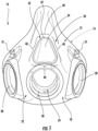
- FIG. 1 is a front view of an embodiment of the respirator mask 10, which is configured to be worn by a user in environments where the user is exposed to hazardous materials, such as, but not limited to, gases, vapors, aerosols (for example, dusts, mists, and/or biological agents), and/or the like.
- the mask 10 includes a body 12 that is sized and configured to cover the nose and mouth of the user. As shown herein, the mask 10 does not cover the user's eyes.
- the illustrated embodiment of the mask described herein is an oronasal half mask 10.
- the mask 10 is not limited to the body 12 shown in the figures. Rather, the mask 10 may be any other type of respiratory mask, such as, but not limited to, a full face respiratory mask and/or the like. In some embodiments, the mask 10 is a disposable respirator mask.
- the body 12 of the mask 10 includes an interior surface 16 and an exterior surface 18 opposite the interior surface 16.
- the body 12 includes a nose area 20 (sometimes referred to as an "upper portion” of the mask body 12) and a mouth area 22 (sometimes referred to as a "lower portion” of the mask body 12).
- the nose area 20 is sized and configured to receive the nose of the user therein such that the nose area 20 covers at least a portion of the user's nose.
- the nose area 20 covers the nose and portions of the upper cheeks of the user.
- the mouth area 22 of the mask 10 is sized and configured to cover the user's mouth.
- the mouth area 22 covers the mouth, at least a portion of the chin, and portions of the lower cheeks of the user.
- the body 12 of the mask 10 includes a sealing area 24 that is configured to seal against the user's face to thereby seal the mask 10 to the user's face.
- the sealing area 24 of the body 12 is defined by one or more flexible lips 26 (as shown in Figure 2 ).
- the sealing area 24 additionally or alternatively may include any other structure, such as, but not limited to, a gasket, a cushion, and/or the like.
- the one or more lips 26 are integrally formed with a single, unitary construction with the remainder of the body 12.
- the lip(s) 26 and/or other structure of the sealing area 24 may be a discrete component that is attached, either removably or fixedly, to the mask body 12.
- the sealing area 24 is defined by a portion of a filtering structure (not shown) of the mask body 12, as is common in many disposable respirator masks wherein the body of the mask is fabricated from a filter material.
- the structure of the sealing area 24 includes a reusable discrete molded member that is attached to the mask body 12 (not shown).
- the body 12 of the mask 10 includes one or more openings 28.
- Each opening 28 is configured to receive one or more an attachable components (not shown), such as a replaceable filter cartridge, a valve, a breathing gas hose, and/or a speech module.
- the body 12 may include any number of the openings 28 depending on the particular application of the mask 10 and the number of attachable components that are used.
- the interior surface 16 of the body 12 has a concave shape such that the interior surface 16 defines an interior space 30 of the body 12 that is sized and configured to receive therein at least a portion of a user's face, such as the user's nose and mouth. While the mask 10 is worn by the user, the user's nose and mouth are received into the interior space 30 such that a plenum is defined between the interior surface 16 of the body 12 and the portion of the user's face received by the mask 10. So, the interior space 30 may be referred to herein as the plenum when the user is wearing the mask 10.
- the plenum holds breathable gas, such as atmospheric air and/or containerized air, that has been, for example, filtered by the mask 10 (such as by using one or more filter cartridges, using the body 12 of the mask 10, and/or the like) and/or supplied by a hose connected to the mask 10 (not shown).
- breathable gas such as atmospheric air and/or containerized air
- the mask 10 optionally includes a harness that is configured to hold the mask body 12 on the user's face and thereby hold the mask 10 in position over the user's nose and mouth.
- the harness includes a plurality of straps (not shown) that are attached to the mask body 12 and are configured to secure the mask 10 to the user's head.
- the mask body 12 may include one or more attachment elements 31 to which the harness may be coupled.
- the harness additionally or alternatively may include any other structure.
- the harness may be reusable.
- the harness is disposable.
- the harness is optionally composed of materials that are relatively easy to sterilize with relatively common sterilization methods.
- the mask body 12 may be composed of any suitable material(s).
- the mask body 12 may be composed of one or more materials that provide the body 12 with at least some flexibility.
- suitable materials but are not limited to, thermosets, thermoplastics, elastomers, thermoplastic elastomers, filtering structures and/or filter materials, cushioning and/or dampening materials, shape memory materials, and/or the like.
- some or an approximate entirety of the mask body 12 is fabricated from one or more filter materials such that at least a portion of the body 12 has a filtering structure.
- the voice transmittal feature 32 is configured to passively enhance the intelligibility of the speech of a user wearing the mask 10.
- the voice transmittal feature 32 is configured to increase the ability of a listener to understand the speech of a user wearing the mask 10.
- the passive voice transmittal feature 32 thereby enhances communication between a user wearing the mask 10 and a listener.
- the passive voice transmittal feature 32 includes a voice transmittal membrane 34 that is configured to vibrate in response to sound waves generated by the user wearing the mask 10.
- the vibration of the voice transmittal membrane 34 transmits the sound waves from the mask interior space 30, that is, from the plenum defined between the user's face and the interior surface 16, to outside the mask body 12, that is, to the ambient or external environment of the user wearing the mask 10.
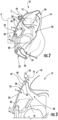
- FIG. 3 shows an enlarged view of the bounded portion A of FIG. 2 . As shown in FIGS.
- the interior surface 36 of the voice transmittal membrane 34 is continuous (i.e., contiguous) with the interior surface 36 of the mask body 12 and the exterior surface 38 is continuous (i.e., contiguous) with the exterior surface 18 of the mask body 12, even though thicknesses T and T 1 are different.
- the voice transmittal membrane 34 thereby passively transmits a user's speech from inside the plenum of the mask body 12 to the ambient environment of the user wearing the mask 10.
- the voice transmittal membrane 34 may be thinner than one or more other segments of the mask body 12 that are adjacent or proximal to the voice transmittal membrane 34.
- the one or more segments 40 may be immediately adjacent to the voice transmittal membrane 34.
- the voice transmittal membrane 34 is thinner as compared to the segments 40 of the mask body 12 that surround the voice transmittal membrane 34.
- the surrounding segments 40 border the voice transmittal membrane 34 along substantially the entirety of the perimeter of the voice transmittal membrane 34.
- the voice transmittal membrane 34 has a thickness T that is less than a thickness T 1 of the surrounding segments 40 of the mask body 12, as is shown in FIGS. 2 and 3 .
- the body 12 may include a transition area between the membrane 34 and the segments 40, in which the thickness of the body 12 increases from the thickness T of the voice transmittal membrane 34 and the thickness T 1 of the segments 40.
- the thicker surrounding segments 40 add strength and structural integrity to the mask body 12. Moreover, the rigidity provided by the thicker surrounding segments 40 may enable and/or facilitate transmission of speech from the plenum of the mask body 12 through the voice transmittal membrane 34. For example, the rigidity provided by the thicker surrounding segments 40 may enable and/or facilitate vibration of the voice transmittal membrane 34 in response to sound waves generated by the user wearing the mask 10.
- the voice transmittal membrane 34 may have any thickness T and may have a uniform thickness T or a non-uniform thickness.
- the surrounding segments 40 may have any thickness T 1 , provided that thickness T 1 is greater than thickness T.
- substantially the entirety of the perimeter of the voice transmittal membrane 34 is surrounded by surrounding segments 40 that are thicker than the voice transmittal membrane 34.
- any amount of the perimeter of the voice transmittal membrane 34 may be surrounded by thicker segments of the mask body 12.
- at least a portion of the surrounding segments 40 may have a thickness T 1 that is greater than a thickness T of at least a portion of the voice transmittal membrane 34.
- the voice transmittal membrane 34 is thinner than a majority and/or a remainder of the mask body 12. Accordingly, the voice transmittal membrane 34 is more flexible than the mask body 12, even if the voice transmittal membrane 34 and the mask body 12 are composed of the same material.
- the passive voice transmittal feature 32 is located along the nose area 20 of the mask body 12, as is shown in FIGS. 1-3 .
- the voice transmittal membrane 34 extends along the nose area 20 of the body 12.
- the passive voice transmittal feature 32 is not limited to this location.
- the passive voice transmittal feature 32 additionally or alternatively may be located at any other location along the mask body 12, such as, but not limited to, the mouth area 22.
- the voice transmittal membrane 34 may be composed of any suitable material(s) that enable the voice transmittal membrane 34 to function as described and/or illustrated herein.
- suitable materials include, but are not limited to, thermosets, thermoplastics, elastomers, thermoplastic elastomers, filtering structures and/or filter materials, cushioning and/or dampening materials, shape memory materials, and/or the like.
- the voice transmittal membrane 34 is composed of substantially the same material(s) as the mask body 12. However, it will be understood that in other examples the voice transmittal membrane 34 may be composed of one or more materials that are different than the material(s) from which the mask body 12 is composed.
- the voice transmittal membrane 34 is fabricated from one or more filter materials (such as in embodiments wherein the mask body 12 is fabricated from a filter material).
- the various design parameters of the mask 10 such as, but not limited to, the material(s) of the mask body 12, the material(s) of the voice transmittal membrane 34, the thickness T, the thickness(es) T 1 , the thickness T of the voice transmittal membrane 34 relative to the value of the thickness T 1 of each surrounding segment 40, the number of surrounding segments 40 that are provided as thicker than the voice transmittal membrane 34, the amount of the perimeter of the voice transmittal membrane 34 that is surrounded by thicker segments of the body 12, the geometry of the voice transmittal membrane 34, the dimensions of the voice transmittal membrane 34, the location of the voice transmittal membrane 34, the orientation of the voice transmittal membrane 34, and/or the like, may be selected to enable the voice transmittal membrane 34 to function as described and/or illustrated herein, that is, to transmit a user's speech from inside the plenum of the mask body 12 to the ambient environment of the user wearing the mask 10 with less distortion such that a listener can better understand the speech of a user wearing the mask 10.
- the passive voice transmittal feature 32 may transmit a user's speech from inside the plenum of the mask body 12 to the ambient environment of the user wearing the mask 10 with less distortion than known respirator masks 10.
- the passive voice transmittal feature 32 thus is configured to increase the ability of a listener to understand the speech of a user wearing the mask 10 and thereby enhance communication between the user and a listener.
- the voice transmittal membrane 34 is a passive device and therefore the amplitude of the user's speech is not enhanced or increased by the passive voice transmittal feature 32.
- the voice transmittal feature 32 is an active voice transmittal feature 32 that includes an active audio capture and/or transmission device that includes or is connected to a power source to increase the amplitude of the user's speech.
- the mask 10 is not precluded from also including a microphone or other amplifier.
- the voice transmittal membrane 34 shown in FIGS. 1-3 is integrally formed with a single, unitary construction with the mask body 12, regardless of whether the voice transmittal membrane 34 is composed of the same material(s) as the mask body 12.
- the single, unitary construction of the voice transmittal membrane 34 with the mask body 12 may allow the passive voice transmittal feature 32 and/or the mask 10 to be less expensive, less prone to failure, and/or the like than respirator masks that include discrete mechanical voice-transmission devices that are mounted or to the mask.
- the voice transmittal membrane 34 is a discrete component that is attached to the mask body 12.
- FIG. 4 is a front view of a preferred embodiment of a respirator mask 110.
- the components disclosed in the example shown in FIGS. 1-3 are at least substantially the same as the corresponding components shown in FIGS. 4-7 that are designated with the same numbers in the one hundred series.
- the mask body 12 shown in FIGS. 1-3 is at least substantially the same as the mask body 112 shown in FIGS. 4-7 , except for any distinguishing features disclosed herein (such as an opening in the mask body to receive a removably attached voice transmittal element, as described in more detail below).
- any distinguishing features disclosed herein such as an opening in the mask body to receive a removably attached voice transmittal element, as described in more detail below.
- the mask body 112 includes an interior surface 116 and an exterior surface 118 opposite the interior surface 116.
- the body 112 includes a nose area 120 (sometimes referred to as an "upper portion” of the mask body 112) and a mouth area 122 (sometimes referred to as a "lower portion” of the mask body 12).
- the nose area 120 is sized and configured to receive the nose of the user therein such that the nose area 120 covers at least a portion of the user's nose.
- the nose area 120 covers the nose and portions of the upper cheeks of the user.
- the mouth area 122 of the mask 110 is sized and configured to cover the user's mouth.
- the mouth area 122 covers the mouth, at least a portion of the chin, and portions of the lower cheeks of the user.
- the mask body includes a sealing area that is similar to the sealing area 24 of the example shown in FIGS. 1-3 in that it is configured to seal against the user's face to thereby seal the mask 110 to the user's face.
- the body 112 of the mask 110 includes one or more openings 128.
- Each opening 128 is configured to receive one or more an attachable components (not shown), such as a replaceable filter cartridge, a valve, a breathing gas hose, and/or a speech module.
- the body 112 may include any number of the openings 128 depending on the particular application of the mask 10 and the number of attachable components that are used.
- the interior surface 116 of the mask body 112 has a concave shape such that the interior surface 116 defines an interior space 130 of the body 112 that is sized and configured to receive therein at least a portion of the user's face, such as the user's nose and mouth. While the mask 110 is worn by the user, the user's nose and mouth are received into the interior space 130 such that a plenum is defined between the interior surface 116 of the body 112 and the portion of the user's face received by the mask 10. So, the interior space 130 may be referred to herein as the plenum when the user is wearing the mask 110.
- the mask 110 optionally includes a harness that is configured to hold the mask body 12 on the user's face and thereby hold the mask 10 in position over the user's nose and mouth.
- the harness includes a plurality of straps (not shown) that are attached to the mask body 112 and are configured to secure the mask 110 to the user's head.
- the mask body01 12 may include one or more attachment elements 131 to which the harness may be coupled.
- the harness additionally or alternatively may include any other structure.
- the harness may be reusable.
- the harness is disposable.
- the harness is optionally composed of materials that are relatively easy to sterilize with relatively common sterilization methods.
- the mask body 112 may be composed of any suitable material(s).
- the mask body 112 may be composed of one or more materials that provide the body 12 with at least some flexibility.
- suitable materials but are not limited to, thermosets, thermoplastics, elastomers, thermoplastic elastomers, filtering structures and/or filter materials, cushioning and/or dampening materials, shape memory materials, and/or the like.
- some or an approximate entirety of the mask body 112 is fabricated from one or more filter materials such that at least a portion of the body 112 has a filtering structure.
- the respiratory mask 110 includes a passive voice transmittal feature 132 that is configured to enhance the intelligibility of the speech of a user wearing the mask 110.
- the passive voice transmittal feature 132 of the embodiment shown in FIGS. 4 and 5 is configured to increase the ability of a listener to understand the speech of a user wearing the mask 110.
- the passive voice transmittal feature 132 thereby enhances communication between a user wearing the mask 110 and a listener.
- the passive voice transmittal feature 132 shown in FIGS. 4 and 5 is not integrally formed with a single, unitary construction with the mask body 112, and instead includes a frame 133 and a voice transmittal membrane 134.
- the voice transmittal membrane 134 is configured to vibrate in response to sound waves generated by the user wearing the mask 110.
- the vibration of the voice transmittal membrane 134 transmits the sound waves from the mask interior space 130, that is, from the plenum defined between the user's face and the interior surface 116, to outside the mask body 112, that is, to the ambient or external environment of the user wearing the mask 110.
- the sound waves generated by the user's speech within the plenum of the mask body 112 impact the voice transmittal membrane 134 along the interior surface 116 of the mask body 112 and, in particular, the interior surface 136 of the voice transmittal membrane 134.
- the impact of the sound waves with the voice transmittal membrane 134 vibrates the voice transmittal membrane 134 such that the sound waves are reproduced by the vibrating membrane 134 along an exterior surface 118 of the mask body 112 and, in particular, the exterior surface 138 of the voice transmittal membrane 134.
- the interior surface 136 of the passive voice transmittal membrane 134 and the frame 133 are continuous (i.e., contiguous) with the interior surface 136 of the mask body 112 and the exterior surface 138 and the frame 133 are continuous (i.e., contiguous) with the exterior surface 118 of the mask body 112, even though the thicknesses of the voice transmittal membrane 134, frame 133, and mask body 112 are different.
- the voice transmittal membrane 134 thereby transmits a user's speech from inside the plenum of the mask body 112 to the ambient environment of the user wearing the mask 110.
- the passive voice transmittal feature 132 includes the voice transmittal membrane 134 and a frame 133.
- the frame 133 is coupled to the mask body 112 such that the frame 133 is secured by the mask body 112, while the voice transmittal membrane 134 is coupled to and secured by the frame 133, as is shown in FIGS. 4 and 5 .
- the frame 133 may be clamped or crimped around the outer edges of the voice transmittal membrane 134 to secure the membrane 134.
- the frame 133 is integrally formed with a single, unitary construction with the mask body 112 and the voice transmittal membrane 134 is removably or fixedly coupled to the frame 133.
- the voice transmittal membrane 134 is integrally formed with a single, unitary construction with the frame 133.
- the frame 133 in which the frame 133 is removably coupled to the mask body 112, the frame 133 includes a perimeter 142 that extends around the outer edge of the frame 133.
- the perimeter 142 has a convex shape in cross section.
- the portion of the mask body 112 that engages with the frame 133 has a perimeter 144 having a corresponding concave shape in cross section.
- the mask body 112 includes an opening 146 that is sized and configured to accept the frame 133 and retain the frame 133 within the mask body 112.
- the convex perimeter 142 of the frame 133 may be snapped into or otherwise coupled to the concave perimeter 144 of the opening 146 in the mask body 112.
- the coupling may fluid tight so a gas within the plenum of the mask does not escape through the opening 146 when the user is wearing the mask 110.
- the frame perimeter 142 may have a concave shape in cross section and the perimeter 144 of the opening 146 may have a corresponding convex shape in cross section that, when the frame 133 is in the opening 146, is capable of retaining the frame within the mask body 112.
- the rigidity of the frame 133 and/or the thickness of the mask body 112 relative to the voice transmittal membrane 134 may enable and/or facilitate operation of the voice transmittal membrane 134 to transmit speech from the plenum of the mask body 112 to the ambient or external environment.
- the rigidity of the frame 133 and/or the thickness of the mask body 112 relative to the voice transmittal membrane 134 may enable and/or facilitate vibration of the voice transmittal membrane 134 in response to sound waves generated by the user wearing the mask 110.
- the passive voice transmittal feature 132 is located along a nose area 120 of the mask body 112, as is shown in FIG. 4 .
- the passive voice transmittal feature 132 is not limited to this location.
- the passive voice transmittal feature 132 additionally or alternatively may be located at any other location along the mask body 112, such as, but not limited to, a mouth area 122.
- the voice transmittal membrane 134 and the frame 133 may each be composed of any suitable material(s) that enable the voice transmittal membrane 34 to function as described and/or illustrated herein.
- suitable materials include, but are not limited to, thermosets, thermoplastics, elastomers, thermoplastic elastomers, filtering structures and/or filter materials, cushioning and/or dampening materials, shape memory materials, and/or the like.
- the voice transmittal membrane 134 is composed of substantially the same material(s) as the mask body 112, whereas the frame 133 is composed of a different, more rigid material.
- the mask body 112 and the voice transmittal membrane 134 may each be composed of a first material having a first durometer and the frame may be composed of a second material having a second durometer that is greater than the first durometer.
- the voice transmittal membrane 134 may be composed of a material that is different than the material from which the mask body 112 is composed, provided that the voice transmittal membrane 134 is composed of a material having a durometer that is less than that of the material from which the frame 133 is composed.
- the various design parameters of the mask 110 such as, but not limited to, the material(s) of the mask body 112, the rigidity of the frame 133, the material(s) of the voice transmittal membrane 134 and/or the frame 133, the thickness of the voice transmittal membrane 134, the thickness(es) of the mask body 112, the thickness of the voice transmittal membrane 134 relative to the thickness(es) of the mask body 112, the geometry of the voice transmittal membrane 134, the dimensions of the voice transmittal membrane 134, the location of the voice transmittal membrane 134, the orientation of the voice transmittal membrane 134, and/or the like, may be selected to enable the voice transmittal membrane 134 to function as described and/or illustrated herein, that is, to transmit a user's speech from inside the plenum of the mask body 112 to the ambient environment of the user wearing the mask 110 with less distortion such that a listener can better understand the speech of a user wearing the mask 110.
- the voice passive transmittal feature 132 may transmit a user's speech from inside the plenum of the mask body 112 to the ambient environment of the user wearing the mask 110 with less distortion than known respirator masks 110.
- the passive voice transmittal feature 132 thus is configured to increase the ability of a listener to understand the speech of a user wearing the mask 110 and thereby enhance communication between the user and a listener.
- the voice transmittal membrane 134 is a passive device and therefore the amplitude of the user's speech is not enhanced or increased by the passive voice transmittal feature 132.
- the passive voice transmittal feature 132 may include an active device that includes or is connected to a power source to increase the amplitude of the user's speech.
- the mask 110 may also include a microphone or other amplifier.
- a respirator mask that includes a passive voice transmittal feature.
- the respirator mask provides respiratory protection while also allowing for the transmission of intelligible speech from a user.
- the respiratory mask includes a body (12)(112) defining an interior space (30)(130) of the mask (10)(110) and including a first surface (16)(116) and a second surface (18)(118) opposite the first surface (16)(116), the first surface (16)(116) defining the interior space (30)(130), and a passive voice transmittal feature (32)(132) contiguous with the body (12)(112).
- the passive voice transmittal feature (32)(132) is a membrane (34)(134), the membrane (34)(134) having a first surface (36)(136), a second surface (38)(138), and a first thickness (T) extending between the membrane first surface (36)(136) and the membrane second surface (38)(138), the body (12)(112) having a second thickness (T 1 ) at at least one location proximate the membrane (34)(134), the second thickness (T 1 ) extending between the body first surface (16)(116) and the body second surface (18)(118), the first thickness (T) being less than the second thickness (T 1 ).
- the membrane first surface (36)(136) is contiguous with the body first surface (16)(116) and the membrane second surface (38)(138) is contiguous with the body second surface (18)(118).
- the membrane (34)(134) has a perimeter, the body (12)(112) further including at least one portion (40) that is adjacent at least a portion of the membrane perimeter, the at least one portion of the body (12)(112) having the second thickness (T 1 ).
- the passive voice transmittal feature (32) is integrally formed with a single, unitary construction with the body (12)(112).
- the body (12)(112) further includes an upper segment (20)(120) and a lower segment (22)(122), the lower segment (22)(122) including the passive voice transmittal feature (32)(132).
- the upper segment (20)(120) is configured to receive a nose of a user and the lower segment (22)(122) is configured to receive a mouth of the user.
- the passive voice transmittal feature (32)(132) is located proximate a user's mouth when the user is wearing the mask (10)(110).
- the voice transmittal membrane (34)(134) is and the body (12)(112) are composed of substantially the same material.
- the passive voice transmittal feature (132) includes a membrane (134) and a frame (133) coupled to the membrane (134), the frame (133) being coupled to the body (112).
- the frame (133) is removably coupled to the body (112).
- the body (112) further includes an opening (146) extending between the body first surface (116) and the body second surface (118), the opening (146) being configured to receive and retain the frame (133).
- the frame (133) is fixedly coupled to the body (112).
- the membrane (134) has a perimeter, the frame (133) being coupled to the perimeter of the membrane (134).
- the passive voice transmittal feature (132) includes a membrane (134) and a frame (133) that is integrally formed with a single, unitary construction with the body (112), the frame (133) being coupled to the membrane perimeter.
Landscapes
- Health & Medical Sciences (AREA)
- General Health & Medical Sciences (AREA)
- Business, Economics & Management (AREA)
- Emergency Management (AREA)
- Pulmonology (AREA)
- Engineering & Computer Science (AREA)
- General Engineering & Computer Science (AREA)
- Physics & Mathematics (AREA)
- Acoustics & Sound (AREA)
- Signal Processing (AREA)
- Mechanical Engineering (AREA)
- Respiratory Apparatuses And Protective Means (AREA)
- Details Of Audible-Bandwidth Transducers (AREA)
- Life Sciences & Earth Sciences (AREA)
- Zoology (AREA)
Description
- The subject matter described and/or illustrated herein relates generally to respirator masks for respiratory protection.
- Respirator masks are used in environments where individuals are exposed to hazardous materials, such as gases, vapors, aerosols (such as dusts, mists, and/or biological agents), and/or the like. Respirator masks come in a large variety of types and sizes, ranging from cheaper, disposable masks to higher cost, reusable masks that include replaceable filtration cartridges. Some respirator masks, such as half mask respirators, cover the mouth and nose of the user but do not cover the user's eyes, while other respirator masks, such as full face mask respirators, cover the user's eyes in addition to the user's mouth and nose.
- Known respirator masks tend to render the speech of the wearer unintelligible, thereby making communication between users difficult. For example, because the respirator mask covers the user's mouth, the body of the respirator mask obstructs the free travel of sound waves from the user's mouth and thereby impairs speech intelligibility. Such speech intelligibility may occur when a user wearing the respirator mask speaks to another person who is not wearing a mask, and/or may occur when two users wearing respirator masks speak with each other. In some circumstances, a user may choose not to wear a respirator mask because of speech intelligibility, which may result in injury to the user's respiratory system.
- Documents
GB 2 264 648 A JP 2000 176033 A US 2 738 788 A andUS 3 124 130 A describe respirator masks having a voice transmitting device in the form of a membrane. - The invention advantageously provides a respirator mask that includes a passive voice transmittal feature as defined in claim 1.
- The respirator mask provides respiratory protection while also allowing for the transmission of intelligible speech from a user. According to the invention, the respiratory mask includes a body defining an interior space of the mask and including a first surface and a second surface opposite the first surface, the first surface defining the interior space, and a passive voice transmittal feature contiguous with the body.
- According to the invention, the passive voice transmittal feature is a membrane. In one embodiment, the membrane has a first surface, a second surface, and a first thickness extending between the membrane first surface and the membrane second surface, the body having a second thickness at at least one location proximate the membrane, the second thickness extending between the body first surface and the body second surface, the first thickness being less than the second thickness.
- In one aspect of the embodiment, the membrane first surface is contiguous with the body first surface and the membrane second surface is contiguous with the body second surface.
- According to an example not part of the invention, the membrane has a perimeter, the body further including at least one portion that is adjacent at least a portion of the membrane perimeter, the at least one portion of the body having the second thickness.
- According to an example not part of the invention, the passive voice transmittal feature is integrally formed with a single, unitary construction with the body.
- In one aspect of the embodiment, the body further includes an upper segment and a lower segment, the lower segment including the passive voice transmittal feature. In one aspect of the embodiment, the upper segment is configured to receive a nose of a user and the lower segment is configured to receive a mouth of the user.
- In one aspect of the embodiment, the passive voice transmittal feature is located proximate a user's mouth when the user is wearing the mask.
- In one aspect of the embodiment, the voice transmittal membrane is and the body are composed of substantially the same material.
- According to the invention, the passive voice transmittal feature includes a membrane and a frame coupled to the membrane, the frame being coupled to the body.
- According to the invention, the frame is removably coupled to the body. According to the invention, the body further includes an opening extending between the body first surface and the body second surface, the opening being configured to receive and retain the frame. According to an example not part of the invention, the frame is fixedly coupled to the body.
- According to an example not part of the invention, the membrane has a perimeter, the frame being coupled to the perimeter of the membrane.
- According to an example not part of the invention, the passive voice transmittal feature includes a membrane and a frame that is integrally formed with a single, unitary construction with the body, the frame being coupled to the membrane perimeter.
-
-
FIG. 1 is a front view of a first embodiment of a respirator mask for providing respiratory protection; -
FIG. 2 is a perspective view illustrating a cross section of the respirator mask shown inFIG. 1 ; -
FIG. 3 is an enlarged cross section view of the bounded portion A of the respirator mask shown inFIG. 2 ; -
FIG. 4 is a front view of a second embodiment of a respirator mask; -
FIG. 5 is a perspective view of an embodiment of a voice transmittal feature of the respirator mask shown inFIG. 4 ; -
FIG. 6 is a cross section view of a first exemplary embodiment of an engagement between a voice transmittal element and the mask body; and -
FIG. 7 is a cross section view of an example not part of the invention of an engagement between a voice transmittal element and the mask body. - Before describing in detail exemplary embodiments that are in accordance with the disclosure, it is noted that components have been represented where appropriate by convention symbols in drawings, showing only those specific details that are pertinent to understanding the embodiments of the disclosure so as not to obscure the disclosure with details that will be readily apparent to those of ordinary skill in the art having the benefit of the description herein.
- As used herein, relational terms, such as "first," "second," "top" and "bottom," and the like, may be used solely to distinguish one entity or element from another entity or element without necessarily requiring or implying any physical or logical relationship or order between such entities or elements. The terminology used herein is for the purpose of describing particular embodiments only and is not intended to be limiting of the concepts described herein. As used herein, the singular forms "a", "an" and "the" are intended to include the plural forms as well, unless the context clearly indicates otherwise. It will be further understood that the terms "comprises," "comprising," "includes" and/or "including" when used herein, specify the presence of stated features, integers, steps, operations, elements, and/or components, but do not preclude the presence or addition of one or more other features, integers, steps, operations, elements, components, and/or groups thereof.
- Unless otherwise defined, all terms (including technical and scientific terms) used herein have the same meaning as commonly understood by one of ordinary skill in the art to which this disclosure belongs. It will be further understood that terms used herein should be interpreted as having a meaning that is consistent with their meaning in the context of this specification and the relevant art and will not be interpreted in an idealized or overly formal sense unless expressly so defined herein.
- Referring now to the drawing figures in which like reference designations refer to like elements, an embodiment of a respirator mask for providing respiratory protection while also allowing for the transmission of voice constructed in accordance with the principles of the invention is shown in the figures and is generally designated as "10."
FIG. 1 is a front view of an embodiment of therespirator mask 10, which is configured to be worn by a user in environments where the user is exposed to hazardous materials, such as, but not limited to, gases, vapors, aerosols (for example, dusts, mists, and/or biological agents), and/or the like. Themask 10 includes abody 12 that is sized and configured to cover the nose and mouth of the user. As shown herein, themask 10 does not cover the user's eyes. Accordingly, the illustrated embodiment of the mask described herein is anoronasal half mask 10. However, it will be understood that themask 10 is not limited to thebody 12 shown in the figures. Rather, themask 10 may be any other type of respiratory mask, such as, but not limited to, a full face respiratory mask and/or the like. In some embodiments, themask 10 is a disposable respirator mask. - The
body 12 of themask 10 includes aninterior surface 16 and anexterior surface 18 opposite theinterior surface 16. Thebody 12 includes a nose area 20 (sometimes referred to as an "upper portion" of the mask body 12) and a mouth area 22 (sometimes referred to as a "lower portion" of the mask body 12). Thenose area 20 is sized and configured to receive the nose of the user therein such that thenose area 20 covers at least a portion of the user's nose. For example, thenose area 20 covers the nose and portions of the upper cheeks of the user. Similarly, themouth area 22 of themask 10 is sized and configured to cover the user's mouth. For example, themouth area 22 covers the mouth, at least a portion of the chin, and portions of the lower cheeks of the user. - The
body 12 of themask 10 includes asealing area 24 that is configured to seal against the user's face to thereby seal themask 10 to the user's face. As a non-limiting example, thesealing area 24 of thebody 12 is defined by one or more flexible lips 26 (as shown inFigure 2 ). However, it will be understood that thesealing area 24 additionally or alternatively may include any other structure, such as, but not limited to, a gasket, a cushion, and/or the like. In thesealing area 24 shown inFIG. 2 , the one ormore lips 26 are integrally formed with a single, unitary construction with the remainder of thebody 12. However, the lip(s) 26 and/or other structure of thesealing area 24 may be a discrete component that is attached, either removably or fixedly, to themask body 12. Optionally, the sealingarea 24 is defined by a portion of a filtering structure (not shown) of themask body 12, as is common in many disposable respirator masks wherein the body of the mask is fabricated from a filter material. In some embodiments, the structure of the sealingarea 24 includes a reusable discrete molded member that is attached to the mask body 12 (not shown). - In the embodiment shown in
FIG. 1 , thebody 12 of themask 10 includes one ormore openings 28. Eachopening 28 is configured to receive one or more an attachable components (not shown), such as a replaceable filter cartridge, a valve, a breathing gas hose, and/or a speech module. Thebody 12 may include any number of theopenings 28 depending on the particular application of themask 10 and the number of attachable components that are used. - As shown in
FIG. 2 , theinterior surface 16 of thebody 12 has a concave shape such that theinterior surface 16 defines aninterior space 30 of thebody 12 that is sized and configured to receive therein at least a portion of a user's face, such as the user's nose and mouth. While themask 10 is worn by the user, the user's nose and mouth are received into theinterior space 30 such that a plenum is defined between theinterior surface 16 of thebody 12 and the portion of the user's face received by themask 10. So, theinterior space 30 may be referred to herein as the plenum when the user is wearing themask 10. During operation of themask 10, the plenum holds breathable gas, such as atmospheric air and/or containerized air, that has been, for example, filtered by the mask 10 (such as by using one or more filter cartridges, using thebody 12 of themask 10, and/or the like) and/or supplied by a hose connected to the mask 10 (not shown). - Although not shown, the
mask 10 optionally includes a harness that is configured to hold themask body 12 on the user's face and thereby hold themask 10 in position over the user's nose and mouth. In some embodiments, the harness includes a plurality of straps (not shown) that are attached to themask body 12 and are configured to secure themask 10 to the user's head. For example, themask body 12 may include one ormore attachment elements 31 to which the harness may be coupled. However, it will be understood that the harness additionally or alternatively may include any other structure. The harness may be reusable. Optionally, the harness is disposable. The harness is optionally composed of materials that are relatively easy to sterilize with relatively common sterilization methods. - The
mask body 12 may be composed of any suitable material(s). For example, themask body 12 may be composed of one or more materials that provide thebody 12 with at least some flexibility. Examples of suitable materials, but are not limited to, thermosets, thermoplastics, elastomers, thermoplastic elastomers, filtering structures and/or filter materials, cushioning and/or dampening materials, shape memory materials, and/or the like. In some embodiments, some or an approximate entirety of themask body 12 is fabricated from one or more filter materials such that at least a portion of thebody 12 has a filtering structure. - Referring now to
FIGS. 1-3 , a first example not part of the invention of a respirator mask having a voice transmittal feature is shown. As will be described in more detail below, the voice transmittal feature 32 is configured to passively enhance the intelligibility of the speech of a user wearing themask 10. In other words, the voice transmittal feature 32 is configured to increase the ability of a listener to understand the speech of a user wearing themask 10. The passive voice transmittal feature 32 thereby enhances communication between a user wearing themask 10 and a listener. - As shown in
FIGS. 1-3 , the passive voice transmittal feature 32 includes avoice transmittal membrane 34 that is configured to vibrate in response to sound waves generated by the user wearing themask 10. The vibration of thevoice transmittal membrane 34 transmits the sound waves from the maskinterior space 30, that is, from the plenum defined between the user's face and theinterior surface 16, to outside themask body 12, that is, to the ambient or external environment of the user wearing themask 10. - Specifically, as the user speaks while wearing the
mask 10, the sound waves generated by the user's speech within the plenum of themask body 12 impact thevoice transmittal membrane 34 along theinterior surface 16 of themask body 12 and, in particular, theinterior surface 36 of thevoice transmittal membrane 34. The impact of the sound waves with thevoice transmittal membrane 34 vibrates thevoice transmittal membrane 34 such that the sound waves are reproduced by the vibratingmembrane 34 along theexterior surface 18 of themask body 12 and, in particular, theexterior surface 38 of thevoice transmittal membrane 34.FIG. 3 shows an enlarged view of the bounded portion A ofFIG. 2 . As shown inFIGS. 2 and 3 , theinterior surface 36 of thevoice transmittal membrane 34 is continuous (i.e., contiguous) with theinterior surface 36 of themask body 12 and theexterior surface 38 is continuous (i.e., contiguous) with theexterior surface 18 of themask body 12, even though thicknesses T and T1 are different. Thevoice transmittal membrane 34 thereby passively transmits a user's speech from inside the plenum of themask body 12 to the ambient environment of the user wearing themask 10. - The
voice transmittal membrane 34 may be thinner than one or more other segments of themask body 12 that are adjacent or proximal to thevoice transmittal membrane 34. As a non-limiting example, the one ormore segments 40 may be immediately adjacent to thevoice transmittal membrane 34. Further, thevoice transmittal membrane 34 is thinner as compared to thesegments 40 of themask body 12 that surround thevoice transmittal membrane 34. Specifically, as shown inFIG. 1 , the surroundingsegments 40 border thevoice transmittal membrane 34 along substantially the entirety of the perimeter of thevoice transmittal membrane 34. Put another way, thevoice transmittal membrane 34 has a thickness T that is less than a thickness T1 of the surroundingsegments 40 of themask body 12, as is shown inFIGS. 2 and 3 . Additionally, thebody 12 may include a transition area between themembrane 34 and thesegments 40, in which the thickness of thebody 12 increases from the thickness T of thevoice transmittal membrane 34 and the thickness T1 of thesegments 40. - The thicker surrounding
segments 40 add strength and structural integrity to themask body 12. Moreover, the rigidity provided by the thicker surroundingsegments 40 may enable and/or facilitate transmission of speech from the plenum of themask body 12 through thevoice transmittal membrane 34. For example, the rigidity provided by the thicker surroundingsegments 40 may enable and/or facilitate vibration of thevoice transmittal membrane 34 in response to sound waves generated by the user wearing themask 10. - The
voice transmittal membrane 34 may have any thickness T and may have a uniform thickness T or a non-uniform thickness. The surroundingsegments 40 may have any thickness T1, provided that thickness T1 is greater than thickness T. In the illustrated example not part of the invention, substantially the entirety of the perimeter of thevoice transmittal membrane 34 is surrounded by surroundingsegments 40 that are thicker than thevoice transmittal membrane 34. However, it will be understood that any amount of the perimeter of the voice transmittal membrane 34 (for example, any number of thesegments 40 or any length thereof) may be surrounded by thicker segments of themask body 12. Put another way, at least a portion of the surroundingsegments 40 may have a thickness T1 that is greater than a thickness T of at least a portion of thevoice transmittal membrane 34. In some examples, thevoice transmittal membrane 34 is thinner than a majority and/or a remainder of themask body 12. Accordingly, thevoice transmittal membrane 34 is more flexible than themask body 12, even if thevoice transmittal membrane 34 and themask body 12 are composed of the same material. - In the illustrated example not part of the invention, the passive voice transmittal feature 32 is located along the
nose area 20 of themask body 12, as is shown inFIGS. 1-3 . Specifically, thevoice transmittal membrane 34 extends along thenose area 20 of thebody 12. However, the passive voice transmittal feature 32 is not limited to this location. For example, the passive voice transmittal feature 32 additionally or alternatively may be located at any other location along themask body 12, such as, but not limited to, themouth area 22. - The
voice transmittal membrane 34 may be composed of any suitable material(s) that enable thevoice transmittal membrane 34 to function as described and/or illustrated herein. Examples of suitable materials include, but are not limited to, thermosets, thermoplastics, elastomers, thermoplastic elastomers, filtering structures and/or filter materials, cushioning and/or dampening materials, shape memory materials, and/or the like. In the illustrated example, thevoice transmittal membrane 34 is composed of substantially the same material(s) as themask body 12. However, it will be understood that in other examples thevoice transmittal membrane 34 may be composed of one or more materials that are different than the material(s) from which themask body 12 is composed. In some examples, thevoice transmittal membrane 34 is fabricated from one or more filter materials (such as in embodiments wherein themask body 12 is fabricated from a filter material). - The various design parameters of the
mask 10, such as, but not limited to, the material(s) of themask body 12, the material(s) of thevoice transmittal membrane 34, the thickness T, the thickness(es) T1, the thickness T of thevoice transmittal membrane 34 relative to the value of the thickness T1 of each surroundingsegment 40, the number of surroundingsegments 40 that are provided as thicker than thevoice transmittal membrane 34, the amount of the perimeter of thevoice transmittal membrane 34 that is surrounded by thicker segments of thebody 12, the geometry of thevoice transmittal membrane 34, the dimensions of thevoice transmittal membrane 34, the location of thevoice transmittal membrane 34, the orientation of thevoice transmittal membrane 34, and/or the like, may be selected to enable thevoice transmittal membrane 34 to function as described and/or illustrated herein, that is, to transmit a user's speech from inside the plenum of themask body 12 to the ambient environment of the user wearing themask 10 with less distortion such that a listener can better understand the speech of a user wearing themask 10. - The passive voice transmittal feature 32 may transmit a user's speech from inside the plenum of the
mask body 12 to the ambient environment of the user wearing themask 10 with less distortion than known respirator masks 10. The passive voice transmittal feature 32 thus is configured to increase the ability of a listener to understand the speech of a user wearing themask 10 and thereby enhance communication between the user and a listener. - Further, it should be understood that in the illustrated example, the
voice transmittal membrane 34 is a passive device and therefore the amplitude of the user's speech is not enhanced or increased by the passive voicetransmittal feature 32. In other examples, the voice transmittal feature 32 is an active voice transmittal feature 32 that includes an active audio capture and/or transmission device that includes or is connected to a power source to increase the amplitude of the user's speech. In other words, as a non-limiting example, themask 10 is not precluded from also including a microphone or other amplifier. - The
voice transmittal membrane 34 shown inFIGS. 1-3 is integrally formed with a single, unitary construction with themask body 12, regardless of whether thevoice transmittal membrane 34 is composed of the same material(s) as themask body 12. The single, unitary construction of thevoice transmittal membrane 34 with themask body 12 may allow the passive voice transmittal feature 32 and/or themask 10 to be less expensive, less prone to failure, and/or the like than respirator masks that include discrete mechanical voice-transmission devices that are mounted or to the mask. - According to the invention, the
voice transmittal membrane 34 is a discrete component that is attached to themask body 12. For example,FIG. 4 is a front view of a preferred embodiment of arespirator mask 110. In general, the components disclosed in the example shown inFIGS. 1-3 are at least substantially the same as the corresponding components shown inFIGS. 4-7 that are designated with the same numbers in the one hundred series. For example, themask body 12 shown inFIGS. 1-3 is at least substantially the same as themask body 112 shown inFIGS. 4-7 , except for any distinguishing features disclosed herein (such as an opening in the mask body to receive a removably attached voice transmittal element, as described in more detail below). Further, it will be understood that features disclosed for one embodiment are not precluded from being included in the other embodiment. - The
mask body 112 includes aninterior surface 116 and anexterior surface 118 opposite theinterior surface 116. Thebody 112 includes a nose area 120 (sometimes referred to as an "upper portion" of the mask body 112) and a mouth area 122 (sometimes referred to as a "lower portion" of the mask body 12). Thenose area 120 is sized and configured to receive the nose of the user therein such that thenose area 120 covers at least a portion of the user's nose. For example, thenose area 120 covers the nose and portions of the upper cheeks of the user. Similarly, themouth area 122 of themask 110 is sized and configured to cover the user's mouth. For example, themouth area 122 covers the mouth, at least a portion of the chin, and portions of the lower cheeks of the user. - Although not shown in
FIG. 4 , the mask body includes a sealing area that is similar to the sealingarea 24 of the example shown inFIGS. 1-3 in that it is configured to seal against the user's face to thereby seal themask 110 to the user's face. - In the embodiment shown in
FIG. 4 , thebody 112 of themask 110 includes one ormore openings 128. Eachopening 128 is configured to receive one or more an attachable components (not shown), such as a replaceable filter cartridge, a valve, a breathing gas hose, and/or a speech module. Thebody 112 may include any number of theopenings 128 depending on the particular application of themask 10 and the number of attachable components that are used. - The
interior surface 116 of themask body 112 has a concave shape such that theinterior surface 116 defines an interior space 130 of thebody 112 that is sized and configured to receive therein at least a portion of the user's face, such as the user's nose and mouth. While themask 110 is worn by the user, the user's nose and mouth are received into the interior space 130 such that a plenum is defined between theinterior surface 116 of thebody 112 and the portion of the user's face received by themask 10. So, the interior space 130 may be referred to herein as the plenum when the user is wearing themask 110. - Although not shown, the
mask 110 optionally includes a harness that is configured to hold themask body 12 on the user's face and thereby hold themask 10 in position over the user's nose and mouth. In some embodiments, the harness includes a plurality of straps (not shown) that are attached to themask body 112 and are configured to secure themask 110 to the user's head. For example, themask body01 12 may include one ormore attachment elements 131 to which the harness may be coupled. However, it will be understood that the harness additionally or alternatively may include any other structure. The harness may be reusable. Optionally, the harness is disposable. The harness is optionally composed of materials that are relatively easy to sterilize with relatively common sterilization methods. - The
mask body 112 may be composed of any suitable material(s). For example, themask body 112 may be composed of one or more materials that provide thebody 12 with at least some flexibility. Examples of suitable materials, but are not limited to, thermosets, thermoplastics, elastomers, thermoplastic elastomers, filtering structures and/or filter materials, cushioning and/or dampening materials, shape memory materials, and/or the like. In some embodiments, some or an approximate entirety of themask body 112 is fabricated from one or more filter materials such that at least a portion of thebody 112 has a filtering structure. - The
respiratory mask 110 includes a passive voice transmittal feature 132 that is configured to enhance the intelligibility of the speech of a user wearing themask 110. In other words, like the passive voice transmittal feature 32 of the example shown inFIGS. 1-3 , the passive voice transmittal feature 132 of the embodiment shown inFIGS. 4 and 5 is configured to increase the ability of a listener to understand the speech of a user wearing themask 110. The passive voice transmittal feature 132 thereby enhances communication between a user wearing themask 110 and a listener. - Unlike the passive voice transmittal feature 132 of the example shown in
FIGS. 1-3 , the passive voice transmittal feature 132 shown inFIGS. 4 and 5 is not integrally formed with a single, unitary construction with themask body 112, and instead includes aframe 133 and avoice transmittal membrane 134. Thevoice transmittal membrane 134 is configured to vibrate in response to sound waves generated by the user wearing themask 110. The vibration of thevoice transmittal membrane 134 transmits the sound waves from the mask interior space 130, that is, from the plenum defined between the user's face and theinterior surface 116, to outside themask body 112, that is, to the ambient or external environment of the user wearing themask 110. - Specifically, as the user speaks while wearing the
mask 110, the sound waves generated by the user's speech within the plenum of themask body 112 impact thevoice transmittal membrane 134 along theinterior surface 116 of themask body 112 and, in particular, theinterior surface 136 of thevoice transmittal membrane 134. The impact of the sound waves with thevoice transmittal membrane 134 vibrates thevoice transmittal membrane 134 such that the sound waves are reproduced by the vibratingmembrane 134 along anexterior surface 118 of themask body 112 and, in particular, theexterior surface 138 of thevoice transmittal membrane 134. Theinterior surface 136 of the passivevoice transmittal membrane 134 and theframe 133 are continuous (i.e., contiguous) with theinterior surface 136 of themask body 112 and theexterior surface 138 and theframe 133 are continuous (i.e., contiguous) with theexterior surface 118 of themask body 112, even though the thicknesses of thevoice transmittal membrane 134,frame 133, andmask body 112 are different. Thevoice transmittal membrane 134 thereby transmits a user's speech from inside the plenum of themask body 112 to the ambient environment of the user wearing themask 110. - Referring now to
FIGS. 4 and 5 , as described above, the passive voice transmittal feature 132 includes thevoice transmittal membrane 134 and aframe 133. In the illustrated embodiment, theframe 133 is coupled to themask body 112 such that theframe 133 is secured by themask body 112, while thevoice transmittal membrane 134 is coupled to and secured by theframe 133, as is shown inFIGS. 4 and 5 . In an example not part of the invention, theframe 133 may be clamped or crimped around the outer edges of thevoice transmittal membrane 134 to secure themembrane 134. In other examples not part of the invention theframe 133 is integrally formed with a single, unitary construction with themask body 112 and thevoice transmittal membrane 134 is removably or fixedly coupled to theframe 133. - According to the invention, the
voice transmittal membrane 134 is integrally formed with a single, unitary construction with theframe 133. - According to the invention, in which the
frame 133 is removably coupled to themask body 112, theframe 133 includes aperimeter 142 that extends around the outer edge of theframe 133. According to the invention, theperimeter 142 has a convex shape in cross section. Further, the portion of themask body 112 that engages with theframe 133 has aperimeter 144 having a corresponding concave shape in cross section. For example, themask body 112 includes anopening 146 that is sized and configured to accept theframe 133 and retain theframe 133 within themask body 112. In this way, theconvex perimeter 142 of theframe 133 may be snapped into or otherwise coupled to theconcave perimeter 144 of theopening 146 in themask body 112. Further, when theframe 133 is coupled to themask body 112, the coupling may fluid tight so a gas within the plenum of the mask does not escape through theopening 146 when the user is wearing themask 110. - According to an example not part of the invention, the
frame perimeter 142 may have a concave shape in cross section and theperimeter 144 of theopening 146 may have a corresponding convex shape in cross section that, when theframe 133 is in theopening 146, is capable of retaining the frame within themask body 112. - The rigidity of the
frame 133 and/or the thickness of themask body 112 relative to thevoice transmittal membrane 134 may enable and/or facilitate operation of thevoice transmittal membrane 134 to transmit speech from the plenum of themask body 112 to the ambient or external environment. For example, the rigidity of theframe 133 and/or the thickness of themask body 112 relative to thevoice transmittal membrane 134 may enable and/or facilitate vibration of thevoice transmittal membrane 134 in response to sound waves generated by the user wearing themask 110. - In the illustrated embodiment, the passive voice transmittal feature 132 is located along a
nose area 120 of themask body 112, as is shown inFIG. 4 . However, the passive voice transmittal feature 132 is not limited to this location. For example, the passive voice transmittal feature 132 additionally or alternatively may be located at any other location along themask body 112, such as, but not limited to, amouth area 122. - The
voice transmittal membrane 134 and theframe 133 may each be composed of any suitable material(s) that enable thevoice transmittal membrane 34 to function as described and/or illustrated herein. Examples of suitable materials include, but are not limited to, thermosets, thermoplastics, elastomers, thermoplastic elastomers, filtering structures and/or filter materials, cushioning and/or dampening materials, shape memory materials, and/or the like. As a non-limiting example, thevoice transmittal membrane 134 is composed of substantially the same material(s) as themask body 112, whereas theframe 133 is composed of a different, more rigid material. For example, themask body 112 and thevoice transmittal membrane 134 may each be composed of a first material having a first durometer and the frame may be composed of a second material having a second durometer that is greater than the first durometer. Alternatively, thevoice transmittal membrane 134 may be composed of a material that is different than the material from which themask body 112 is composed, provided that thevoice transmittal membrane 134 is composed of a material having a durometer that is less than that of the material from which theframe 133 is composed. - The various design parameters of the
mask 110, such as, but not limited to, the material(s) of themask body 112, the rigidity of theframe 133, the material(s) of thevoice transmittal membrane 134 and/or theframe 133, the thickness of thevoice transmittal membrane 134, the thickness(es) of themask body 112, the thickness of thevoice transmittal membrane 134 relative to the thickness(es) of themask body 112, the geometry of thevoice transmittal membrane 134, the dimensions of thevoice transmittal membrane 134, the location of thevoice transmittal membrane 134, the orientation of thevoice transmittal membrane 134, and/or the like, may be selected to enable thevoice transmittal membrane 134 to function as described and/or illustrated herein, that is, to transmit a user's speech from inside the plenum of themask body 112 to the ambient environment of the user wearing themask 110 with less distortion such that a listener can better understand the speech of a user wearing themask 110. - The voice passive transmittal feature 132 may transmit a user's speech from inside the plenum of the
mask body 112 to the ambient environment of the user wearing themask 110 with less distortion than known respirator masks 110. The passive voice transmittal feature 132 thus is configured to increase the ability of a listener to understand the speech of a user wearing themask 110 and thereby enhance communication between the user and a listener. - Further, it should be understood that in the illustrated embodiment, the
voice transmittal membrane 134 is a passive device and therefore the amplitude of the user's speech is not enhanced or increased by the passive voicetransmittal feature 132. In other embodiments, the passive voice transmittal feature 132 may include an active device that includes or is connected to a power source to increase the amplitude of the user's speech. As a non-limiting example, themask 110 may also include a microphone or other amplifier. - In some embodiments, a respirator mask that includes a passive voice transmittal feature is provided. The respirator mask provides respiratory protection while also allowing for the transmission of intelligible speech from a user. In one embodiment, the respiratory mask includes a body (12)(112) defining an interior space (30)(130) of the mask (10)(110) and including a first surface (16)(116) and a second surface (18)(118) opposite the first surface (16)(116), the first surface (16)(116) defining the interior space (30)(130), and a passive voice transmittal feature (32)(132) contiguous with the body (12)(112).
- In one aspect of the embodiment, the passive voice transmittal feature (32)(132) is a membrane (34)(134), the membrane (34)(134) having a first surface (36)(136), a second surface (38)(138), and a first thickness (T) extending between the membrane first surface (36)(136) and the membrane second surface (38)(138), the body (12)(112) having a second thickness (T1) at at least one location proximate the membrane (34)(134), the second thickness (T1) extending between the body first surface (16)(116) and the body second surface (18)(118), the first thickness (T) being less than the second thickness (T1).
- In one aspect of the embodiment, the membrane first surface (36)(136) is contiguous with the body first surface (16)(116) and the membrane second surface (38)(138) is contiguous with the body second surface (18)(118).
- In one aspect not part of the invention, the membrane (34)(134) has a perimeter, the body (12)(112) further including at least one portion (40) that is adjacent at least a portion of the membrane perimeter, the at least one portion of the body (12)(112) having the second thickness (T1).
- In one aspect not part of the invention, the passive voice transmittal feature (32) is integrally formed with a single, unitary construction with the body (12)(112).
- In one aspect of the embodiment, the body (12)(112) further includes an upper segment (20)(120) and a lower segment (22)(122), the lower segment (22)(122) including the passive voice transmittal feature (32)(132). In one aspect of the embodiment, the upper segment (20)(120) is configured to receive a nose of a user and the lower segment (22)(122) is configured to receive a mouth of the user.
- In one aspect of the embodiment, the passive voice transmittal feature (32)(132) is located proximate a user's mouth when the user is wearing the mask (10)(110).
- In one aspect of the embodiment, the voice transmittal membrane (34)(134) is and the body (12)(112) are composed of substantially the same material.
- According to the invention, the passive voice transmittal feature (132) includes a membrane (134) and a frame (133) coupled to the membrane (134), the frame (133) being coupled to the body (112).
- According to the invention, the frame (133) is removably coupled to the body (112).
- According to the invention, the body (112) further includes an opening (146) extending between the body first surface (116) and the body second surface (118), the opening (146) being configured to receive and retain the frame (133). According an example not part of the invention, the frame (133) is fixedly coupled to the body (112).
- According an example not part of the invention, the membrane (134) has a perimeter, the frame (133) being coupled to the perimeter of the membrane (134).
- According an example not part of the invention, the passive voice transmittal feature (132) includes a membrane (134) and a frame (133) that is integrally formed with a single, unitary construction with the body (112), the frame (133) being coupled to the membrane perimeter.
- It is to be understood that the above description is intended to be illustrative, and not restrictive. For example, the above-described embodiments (and/or aspects thereof) may be used in combination with each other. In addition, many modifications may be made to adapt a particular situation or material to the teachings of the invention without departing from its scope. Dimensions, types of materials, orientations of the various components, and the number and positions of the various components described herein are intended to define parameters of certain embodiments, and are by no means limiting and are merely exemplary embodiments. Many other embodiments and modifications within the scope of the claims will be apparent to those of skill in the art upon reviewing the above description.
- The scope of the invention should, therefore, be determined with reference to the appended claims.
- In the appended claims, the terms "including" and "in which" are used as the plain-English equivalents of the respective terms "comprising" and "wherein." Moreover, in the following claims, the terms "first," "second," and "third," etc. are used merely as labels, and are not intended to impose numerical requirements on their objects.
Claims (10)
- A respirator mask (110), comprising:a body (112) defining an interior space (130) of the mask (110) and including a first surface (116) and a second surface (118) opposite the first surface (116), the first surface (116) defining the interior space (130); anda passive voice transmittal feature (132) contiguous with the body (112), the voice transmittal feature (132) including a membrane (134) and a frame (133), the membrane (134) being integrally formed with a single unitary construction with the frame (133), the frame (133) and the membrane (134) being removably coupled to the body (112) , wherein the frame (133) includes a perimeter (142) that extends around the outer edge of the frame and that has a convex shape in cross section,and wherein the body (112) comprises an opening (146) that is sized and configured to accept the frame (133) with the opening (146) comprising a perimeter (144) having a concave shape in cross section.
- The respirator mask (110) of Claim 1, wherein the membrane (134) has a first surface (136), a second surface (138), and a first thickness (T) extending between the membrane first surface (136) and the membrane second surface (138), the body (112) having a second thickness (T1) at least one location proximate the membrane (134), the second thickness (T1) extending between the body first surface (116) and the body second surface (118), the first thickness (T) being less than the second thickness (T1).
- The respirator mask (110) of Claim 2, wherein the membrane first surface (136) and the frame (133) are contiguous with the body first surface (116) and the membrane second surface (138) and the frame (133) are contiguous with the body second surface (118).
- The respirator mask (110) of Claim 1, wherein the body (112) further includes an upper segment (120) and a lower segment (122), the lower segment (122) including the passive voice transmittal feature (132).
- The respirator mask (110) of Claim 4, wherein the upper segment (120) is configured to receive a nose of a user and the lower segment (122) is configured to receive a mouth of the user.
- The respirator mask (110) of Claim 1, wherein the body (112) further includes an upper segment (120) and a lower segment (122), the upper segment (120) including the passive voice transmittal feature (132).
- The respirator mask (110) of Claim 6, wherein the upper segment (120) is configured to receive a nose of a user and the lower segment (122) is configured to receive a mouth of the user.
- The respirator mask (110) of Claim 1, wherein the passive voice transmittal feature (132) is located proximate a user's mouth when the user is wearing the mask (110).
- The respirator mask (110) of Claim 1, wherein the voice transmittal membrane (134) and the body (112) are composed of substantially the same material.
- The respirator mask (110) of Claim 1, wherein the membrane (134) has a perimeter and the frame (133) extends around the perimeter.
Applications Claiming Priority (2)
| Application Number | Priority Date | Filing Date | Title |
|---|---|---|---|
| US201562244917P | 2015-10-22 | 2015-10-22 | |
| PCT/US2016/057921 WO2017070352A1 (en) | 2015-10-22 | 2016-10-20 | Respirator mask with voice transmittal feature |
Publications (3)
| Publication Number | Publication Date |
|---|---|
| EP3365075A1 EP3365075A1 (en) | 2018-08-29 |
| EP3365075A4 EP3365075A4 (en) | 2019-05-15 |
| EP3365075B1 true EP3365075B1 (en) | 2024-12-11 |
Family
ID=58558246
Family Applications (1)
| Application Number | Title | Priority Date | Filing Date |
|---|---|---|---|
| EP16858218.7A Active EP3365075B1 (en) | 2015-10-22 | 2016-10-20 | Respirator mask with voice transmittal feature |
Country Status (7)
| Country | Link |
|---|---|
| US (1) | US11273334B2 (en) |
| EP (1) | EP3365075B1 (en) |
| JP (2) | JP2018531104A (en) |
| KR (1) | KR102749643B1 (en) |
| CN (1) | CN108367182A (en) |
| AU (1) | AU2016342193B2 (en) |
| WO (1) | WO2017070352A1 (en) |
Families Citing this family (16)
| Publication number | Priority date | Publication date | Assignee | Title |
|---|---|---|---|---|
| US11878124B2 (en) | 2017-11-09 | 2024-01-23 | Fisher & Paykel Healthcare Limited | Patient interface and a speech valve therefor |
| US20220193469A1 (en) * | 2018-04-18 | 2022-06-23 | Orindi Ventures, LLC | Face mask for regulating heat and humidity |
| CA3165531A1 (en) * | 2020-01-20 | 2021-07-29 | Richard Devin SZASZ | Tactical respirator mask |
| KR200494337Y1 (en) | 2020-05-28 | 2021-09-16 | 양경호 | Sound Transmitting Device for Mask |
| US20210393997A1 (en) * | 2020-06-19 | 2021-12-23 | Msa Technology, Llc | Respirator mask with exhalation filter |
| KR200496018Y1 (en) | 2020-07-08 | 2022-10-14 | 양경호 | Sound Transmitting Device for Mask |
| USD958966S1 (en) * | 2020-07-21 | 2022-07-26 | Desprez, Llc | Face mask |
| KR200496058Y1 (en) | 2020-07-28 | 2022-10-24 | 양경호 | Sound Transmitting Device for Mask |
| KR102234853B1 (en) | 2020-09-16 | 2021-04-01 | 양경호 | Sound Transmitting Device for Mask |
| US20230310909A1 (en) * | 2020-08-14 | 2023-10-05 | Cafe24 Corp. | 3d printing-based face mask |
| CN116133724B (en) * | 2020-08-14 | 2026-07-21 | 咖啡24株式会社 | Face shape mask based on 3D prints |
| KR20220046314A (en) | 2020-10-07 | 2022-04-14 | 주식회사퓨먼 | Face Mask Of Enhancing Speech Transmission Quality By Means Of Fibonacci Sequence |
| KR102487561B1 (en) | 2021-02-16 | 2023-01-12 | 주식회사 이보 | Sound Transmitting Device for Mask |
| USD1001271S1 (en) * | 2021-03-18 | 2023-10-10 | Tecmen Electronics Co., Ltd | Respirator |
| EP4384284A4 (en) * | 2021-08-13 | 2025-06-11 | The University of Melbourne | FACE MASK |
| KR20230108105A (en) | 2022-01-10 | 2023-07-18 | 주식회사 이보 | Sound Transmitting Device for Mask |
Family Cites Families (24)
| Publication number | Priority date | Publication date | Assignee | Title |
|---|---|---|---|---|
| US3124130A (en) * | 1964-03-10 | Respirator with speaking diaphragm | ||
| US1762695A (en) * | 1924-05-14 | 1930-06-10 | Monro Randolph | Gas mask |
| US2164330A (en) * | 1937-07-10 | 1939-07-04 | Sidney H Katz | Fully molded gas mask facepiece |
| US2738788A (en) * | 1952-04-08 | 1956-03-20 | Willson Products Inc | Respirator with speaking diaphragm |
| US3602219A (en) * | 1969-03-05 | 1971-08-31 | Draegerwerk Ag | Respirator having sound diaphragm protective cavity |
| DE3374173D1 (en) | 1982-08-18 | 1987-12-03 | Avon Ind Polymers | Respirator speech transmitter |
| JPS59156356A (en) * | 1983-02-25 | 1984-09-05 | 株式会社 笠井仏檀工芸 | Working mask |
| AT378652B (en) * | 1983-12-27 | 1985-09-10 | Akg Akustische Kino Geraete | ARRANGEMENT FOR VOICE TRANSFER FROM A RESPIRATORY MASK |
| JPH0680660B2 (en) | 1984-01-23 | 1994-10-12 | 沖電気工業株式会社 | Method for manufacturing semiconductor device |
| JPS60153145U (en) * | 1984-03-22 | 1985-10-12 | 笠井 武 | work mask |
| JPS6148747A (en) | 1984-08-16 | 1986-03-10 | Canon Inc | Particle analysis device |
| JPS6148747U (en) * | 1984-09-03 | 1986-04-01 | ||
| FI96171C (en) * | 1992-03-02 | 1996-05-27 | Kemira Oy | protective mask |
| US5385141A (en) | 1992-04-16 | 1995-01-31 | Siebe North, Inc. | Speech diaphragm and exhalation valve |
| US5895537A (en) | 1997-10-09 | 1999-04-20 | Campbell; Richard G. | Sonic welded gas mask and process |
| JP3012845B1 (en) * | 1998-12-15 | 2000-02-28 | 興研株式会社 | Mask with voice function |
| JP3234196B2 (en) * | 1998-12-28 | 2001-12-04 | 興研株式会社 | Facepiece mounting speaker |
| CN2667838Y (en) * | 2003-10-27 | 2004-12-29 | 北京三方杰科技有限公司 | Gas mask electroacoustical transducer |
| JP2010537721A (en) | 2007-08-31 | 2010-12-09 | スリーエム イノベイティブ プロパティズ カンパニー | Integrated respirator with molded thermoset elastomeric elements |
| RU2429034C1 (en) | 2007-08-31 | 2011-09-20 | 3М Инновейтив Пропертиз Компани | Face mask of respirator with thermally hardened elastomeric face seal |
| US20120260920A1 (en) | 2011-04-15 | 2012-10-18 | 3M Innovative Properties Company | Face mask having welded thermoplastic mask body |
| JP5759032B2 (en) * | 2013-02-15 | 2015-08-05 | 興研株式会社 | Loudspeaker |
| CN204293714U (en) * | 2014-12-12 | 2015-04-29 | 湖北华强科技有限责任公司 | One is convenient to breathing mask of conversing |
| JP3234196U (en) | 2021-07-16 | 2021-09-24 | 株式会社富士山静養園 | Corrugated tube cottage and locking member |
-
2016
- 2016-10-20 WO PCT/US2016/057921 patent/WO2017070352A1/en not_active Ceased
- 2016-10-20 KR KR1020187014231A patent/KR102749643B1/en active Active
- 2016-10-20 EP EP16858218.7A patent/EP3365075B1/en active Active
- 2016-10-20 AU AU2016342193A patent/AU2016342193B2/en not_active Ceased
- 2016-10-20 US US15/769,846 patent/US11273334B2/en active Active
- 2016-10-20 JP JP2018520473A patent/JP2018531104A/en active Pending
- 2016-10-20 CN CN201680062087.2A patent/CN108367182A/en active Pending
-
2021
- 2021-06-16 JP JP2021100434A patent/JP7426001B2/en active Active
Also Published As
| Publication number | Publication date |
|---|---|
| JP2021164659A (en) | 2021-10-14 |
| AU2016342193A1 (en) | 2018-05-10 |
| WO2017070352A1 (en) | 2017-04-27 |
| US11273334B2 (en) | 2022-03-15 |
| JP2018531104A (en) | 2018-10-25 |
| KR20180115670A (en) | 2018-10-23 |
| JP7426001B2 (en) | 2024-02-01 |
| CN108367182A (en) | 2018-08-03 |
| EP3365075A1 (en) | 2018-08-29 |
| US20180311516A1 (en) | 2018-11-01 |
| AU2016342193B2 (en) | 2019-08-22 |
| KR102749643B1 (en) | 2025-01-02 |
| EP3365075A4 (en) | 2019-05-15 |
Similar Documents
| Publication | Publication Date | Title |
|---|---|---|
| US11273334B2 (en) | Respirator mask with voice transmittal feature | |
| JP2018531104A6 (en) | Respirator with voice transmission function | |
| ES2292748T3 (en) | RESPIRATOR VALVE. | |
| CA2456216C (en) | Respirator | |
| CA2988933C (en) | Face mask assembly | |
| US11266861B2 (en) | Face mask assembly | |
| US11123581B1 (en) | Anti-contagion mask | |
| KR102325079B1 (en) | Multi-purpose dust proof mask | |
| US20210298387A1 (en) | Protective mask accessories | |
| US20210393997A1 (en) | Respirator mask with exhalation filter | |
| US20230356010A1 (en) | Head encapsulation unit | |
| US20230142434A1 (en) | Face mask apparatus with secondary filter | |
| US20190151687A1 (en) | Face seal for respirator mask | |
| KR20120000306A (en) | Voice transmission module for gas mask | |
| CN103041523B (en) | Respiratory protection face shield | |
| KR20200117929A (en) | Hygiene mask | |
| EP3965900B1 (en) | Facepiece chin retention feature | |
| US11957938B1 (en) | Hydration providing mask apparatus | |
| KR20130115534A (en) | An airtight mask for easy communication |
Legal Events
| Date | Code | Title | Description |
|---|---|---|---|
| STAA | Information on the status of an ep patent application or granted ep patent |
Free format text: STATUS: THE INTERNATIONAL PUBLICATION HAS BEEN MADE |
|
| PUAI | Public reference made under article 153(3) epc to a published international application that has entered the european phase |
Free format text: ORIGINAL CODE: 0009012 |
|
| STAA | Information on the status of an ep patent application or granted ep patent |
Free format text: STATUS: REQUEST FOR EXAMINATION WAS MADE |
|
| 17P | Request for examination filed |
Effective date: 20180503 |
|
| AK | Designated contracting states |
Kind code of ref document: A1 Designated state(s): AL AT BE BG CH CY CZ DE DK EE ES FI FR GB GR HR HU IE IS IT LI LT LU LV MC MK MT NL NO PL PT RO RS SE SI SK SM TR |
|
| AX | Request for extension of the european patent |
Extension state: BA ME |
|
| DAV | Request for validation of the european patent (deleted) | ||
| DAX | Request for extension of the european patent (deleted) | ||
| A4 | Supplementary search report drawn up and despatched |
Effective date: 20190416 |
|
| RIC1 | Information provided on ipc code assigned before grant |
Ipc: A62B 18/08 20060101AFI20190410BHEP Ipc: H04R 1/08 20060101ALI20190410BHEP Ipc: A62B 18/02 20060101ALI20190410BHEP |
|
| STAA | Information on the status of an ep patent application or granted ep patent |
Free format text: STATUS: EXAMINATION IS IN PROGRESS |
|
| 17Q | First examination report despatched |
Effective date: 20221027 |
|
| GRAP | Despatch of communication of intention to grant a patent |
Free format text: ORIGINAL CODE: EPIDOSNIGR1 |
|
| STAA | Information on the status of an ep patent application or granted ep patent |
Free format text: STATUS: GRANT OF PATENT IS INTENDED |
|
| INTG | Intention to grant announced |
Effective date: 20240709 |
|
| GRAS | Grant fee paid |
Free format text: ORIGINAL CODE: EPIDOSNIGR3 |
|
| GRAA | (expected) grant |
Free format text: ORIGINAL CODE: 0009210 |
|
| STAA | Information on the status of an ep patent application or granted ep patent |
Free format text: STATUS: THE PATENT HAS BEEN GRANTED |
|
| P01 | Opt-out of the competence of the unified patent court (upc) registered |
Free format text: CASE NUMBER: APP_53636/2024 Effective date: 20240926 |
|
| AK | Designated contracting states |
Kind code of ref document: B1 Designated state(s): AL AT BE BG CH CY CZ DE DK EE ES FI FR GB GR HR HU IE IS IT LI LT LU LV MC MK MT NL NO PL PT RO RS SE SI SK SM TR |
|
| REG | Reference to a national code |
Ref country code: GB Ref legal event code: FG4D |
|
| REG | Reference to a national code |
Ref country code: CH Ref legal event code: EP |
|
| REG | Reference to a national code |
Ref country code: IE Ref legal event code: FG4D |
|
| REG | Reference to a national code |
Ref country code: DE Ref legal event code: R096 Ref document number: 602016090619 Country of ref document: DE |
|
| REG | Reference to a national code |
Ref country code: LT Ref legal event code: MG9D |
|
| PG25 | Lapsed in a contracting state [announced via postgrant information from national office to epo] |
Ref country code: HR Free format text: LAPSE BECAUSE OF FAILURE TO SUBMIT A TRANSLATION OF THE DESCRIPTION OR TO PAY THE FEE WITHIN THE PRESCRIBED TIME-LIMIT Effective date: 20241211 |
|
| PG25 | Lapsed in a contracting state [announced via postgrant information from national office to epo] |
Ref country code: FI Free format text: LAPSE BECAUSE OF FAILURE TO SUBMIT A TRANSLATION OF THE DESCRIPTION OR TO PAY THE FEE WITHIN THE PRESCRIBED TIME-LIMIT Effective date: 20241211 |
|
| PG25 | Lapsed in a contracting state [announced via postgrant information from national office to epo] |
Ref country code: BG Free format text: LAPSE BECAUSE OF FAILURE TO SUBMIT A TRANSLATION OF THE DESCRIPTION OR TO PAY THE FEE WITHIN THE PRESCRIBED TIME-LIMIT Effective date: 20241211 |
|
| REG | Reference to a national code |
Ref country code: NL Ref legal event code: MP Effective date: 20241211 |
|
| PG25 | Lapsed in a contracting state [announced via postgrant information from national office to epo] |
Ref country code: ES Free format text: LAPSE BECAUSE OF FAILURE TO SUBMIT A TRANSLATION OF THE DESCRIPTION OR TO PAY THE FEE WITHIN THE PRESCRIBED TIME-LIMIT Effective date: 20241211 |
|
| PG25 | Lapsed in a contracting state [announced via postgrant information from national office to epo] |
Ref country code: NO Free format text: LAPSE BECAUSE OF FAILURE TO SUBMIT A TRANSLATION OF THE DESCRIPTION OR TO PAY THE FEE WITHIN THE PRESCRIBED TIME-LIMIT Effective date: 20250311 |
|
| PG25 | Lapsed in a contracting state [announced via postgrant information from national office to epo] |
Ref country code: LV Free format text: LAPSE BECAUSE OF FAILURE TO SUBMIT A TRANSLATION OF THE DESCRIPTION OR TO PAY THE FEE WITHIN THE PRESCRIBED TIME-LIMIT Effective date: 20241211 Ref country code: GR Free format text: LAPSE BECAUSE OF FAILURE TO SUBMIT A TRANSLATION OF THE DESCRIPTION OR TO PAY THE FEE WITHIN THE PRESCRIBED TIME-LIMIT Effective date: 20250312 |
|
| PG25 | Lapsed in a contracting state [announced via postgrant information from national office to epo] |
Ref country code: RS Free format text: LAPSE BECAUSE OF FAILURE TO SUBMIT A TRANSLATION OF THE DESCRIPTION OR TO PAY THE FEE WITHIN THE PRESCRIBED TIME-LIMIT Effective date: 20250311 |
|
| PG25 | Lapsed in a contracting state [announced via postgrant information from national office to epo] |
Ref country code: NL Free format text: LAPSE BECAUSE OF FAILURE TO SUBMIT A TRANSLATION OF THE DESCRIPTION OR TO PAY THE FEE WITHIN THE PRESCRIBED TIME-LIMIT Effective date: 20241211 |
|
| REG | Reference to a national code |
Ref country code: AT Ref legal event code: MK05 Ref document number: 1749941 Country of ref document: AT Kind code of ref document: T Effective date: 20241211 |
|
| PG25 | Lapsed in a contracting state [announced via postgrant information from national office to epo] |
Ref country code: SM Free format text: LAPSE BECAUSE OF FAILURE TO SUBMIT A TRANSLATION OF THE DESCRIPTION OR TO PAY THE FEE WITHIN THE PRESCRIBED TIME-LIMIT Effective date: 20241211 |
|
| PG25 | Lapsed in a contracting state [announced via postgrant information from national office to epo] |
Ref country code: PL Free format text: LAPSE BECAUSE OF FAILURE TO SUBMIT A TRANSLATION OF THE DESCRIPTION OR TO PAY THE FEE WITHIN THE PRESCRIBED TIME-LIMIT Effective date: 20241211 |
|
| PG25 | Lapsed in a contracting state [announced via postgrant information from national office to epo] |
Ref country code: IS Free format text: LAPSE BECAUSE OF FAILURE TO SUBMIT A TRANSLATION OF THE DESCRIPTION OR TO PAY THE FEE WITHIN THE PRESCRIBED TIME-LIMIT Effective date: 20250411 |
|
| PG25 | Lapsed in a contracting state [announced via postgrant information from national office to epo] |
Ref country code: PT Free format text: LAPSE BECAUSE OF FAILURE TO SUBMIT A TRANSLATION OF THE DESCRIPTION OR TO PAY THE FEE WITHIN THE PRESCRIBED TIME-LIMIT Effective date: 20250411 |
|
| PG25 | Lapsed in a contracting state [announced via postgrant information from national office to epo] |
Ref country code: EE Free format text: LAPSE BECAUSE OF FAILURE TO SUBMIT A TRANSLATION OF THE DESCRIPTION OR TO PAY THE FEE WITHIN THE PRESCRIBED TIME-LIMIT Effective date: 20241211 |
|
| PG25 | Lapsed in a contracting state [announced via postgrant information from national office to epo] |
Ref country code: RO Free format text: LAPSE BECAUSE OF FAILURE TO SUBMIT A TRANSLATION OF THE DESCRIPTION OR TO PAY THE FEE WITHIN THE PRESCRIBED TIME-LIMIT Effective date: 20241211 Ref country code: AT Free format text: LAPSE BECAUSE OF FAILURE TO SUBMIT A TRANSLATION OF THE DESCRIPTION OR TO PAY THE FEE WITHIN THE PRESCRIBED TIME-LIMIT Effective date: 20241211 |
|
| PG25 | Lapsed in a contracting state [announced via postgrant information from national office to epo] |
Ref country code: SK Free format text: LAPSE BECAUSE OF FAILURE TO SUBMIT A TRANSLATION OF THE DESCRIPTION OR TO PAY THE FEE WITHIN THE PRESCRIBED TIME-LIMIT Effective date: 20241211 |
|
| PG25 | Lapsed in a contracting state [announced via postgrant information from national office to epo] |
Ref country code: CZ Free format text: LAPSE BECAUSE OF FAILURE TO SUBMIT A TRANSLATION OF THE DESCRIPTION OR TO PAY THE FEE WITHIN THE PRESCRIBED TIME-LIMIT Effective date: 20241211 |
|
| PG25 | Lapsed in a contracting state [announced via postgrant information from national office to epo] |
Ref country code: IT Free format text: LAPSE BECAUSE OF FAILURE TO SUBMIT A TRANSLATION OF THE DESCRIPTION OR TO PAY THE FEE WITHIN THE PRESCRIBED TIME-LIMIT Effective date: 20241211 |
|
| PG25 | Lapsed in a contracting state [announced via postgrant information from national office to epo] |
Ref country code: SE Free format text: LAPSE BECAUSE OF FAILURE TO SUBMIT A TRANSLATION OF THE DESCRIPTION OR TO PAY THE FEE WITHIN THE PRESCRIBED TIME-LIMIT Effective date: 20241211 |
|
| REG | Reference to a national code |
Ref country code: DE Ref legal event code: R097 Ref document number: 602016090619 Country of ref document: DE |
|
| PG25 | Lapsed in a contracting state [announced via postgrant information from national office to epo] |
Ref country code: DK Free format text: LAPSE BECAUSE OF FAILURE TO SUBMIT A TRANSLATION OF THE DESCRIPTION OR TO PAY THE FEE WITHIN THE PRESCRIBED TIME-LIMIT Effective date: 20241211 |
|
| PLBE | No opposition filed within time limit |
Free format text: ORIGINAL CODE: 0009261 |
|
| STAA | Information on the status of an ep patent application or granted ep patent |
Free format text: STATUS: NO OPPOSITION FILED WITHIN TIME LIMIT |
|
| REG | Reference to a national code |
Ref country code: CH Ref legal event code: L10 Free format text: ST27 STATUS EVENT CODE: U-0-0-L10-L00 (AS PROVIDED BY THE NATIONAL OFFICE) Effective date: 20251022 |
|
| 26N | No opposition filed |
Effective date: 20250912 |
|
| PGFP | Annual fee paid to national office [announced via postgrant information from national office to epo] |
Ref country code: DE Payment date: 20250923 Year of fee payment: 10 |
|
| REG | Reference to a national code |
Ref country code: CH Ref legal event code: H13 Free format text: ST27 STATUS EVENT CODE: U-0-0-H10-H13 (AS PROVIDED BY THE NATIONAL OFFICE) Effective date: 20260527 |
|
| PG25 | Lapsed in a contracting state [announced via postgrant information from national office to epo] |
Ref country code: LU Free format text: LAPSE BECAUSE OF NON-PAYMENT OF DUE FEES Effective date: 20251020 |
|
| REG | Reference to a national code |
Ref country code: BE Ref legal event code: MM Effective date: 20251031 |
|
| GBPC | Gb: european patent ceased through non-payment of renewal fee |
Effective date: 20251020 |
|
| PG25 | Lapsed in a contracting state [announced via postgrant information from national office to epo] |
Ref country code: LT Free format text: LAPSE BECAUSE OF FAILURE TO SUBMIT A TRANSLATION OF THE DESCRIPTION OR TO PAY THE FEE WITHIN THE PRESCRIBED TIME-LIMIT Effective date: 20241211 |
|
| PG25 | Lapsed in a contracting state [announced via postgrant information from national office to epo] |
Ref country code: MC Free format text: LAPSE BECAUSE OF FAILURE TO SUBMIT A TRANSLATION OF THE DESCRIPTION OR TO PAY THE FEE WITHIN THE PRESCRIBED TIME-LIMIT Effective date: 20241211 |
|
| PG25 | Lapsed in a contracting state [announced via postgrant information from national office to epo] |
Ref country code: GB Free format text: LAPSE BECAUSE OF NON-PAYMENT OF DUE FEES Effective date: 20251020 |
|
| PG25 | Lapsed in a contracting state [announced via postgrant information from national office to epo] |
Ref country code: BE Free format text: LAPSE BECAUSE OF NON-PAYMENT OF DUE FEES Effective date: 20251031 Ref country code: CH Free format text: LAPSE BECAUSE OF NON-PAYMENT OF DUE FEES Effective date: 20251031 |
|
| PG25 | Lapsed in a contracting state [announced via postgrant information from national office to epo] |
Ref country code: FR Free format text: LAPSE BECAUSE OF NON-PAYMENT OF DUE FEES Effective date: 20251031 |