EP3365072B1 - Dispositifs et systèmes de circuit respiratoire - Google Patents
Dispositifs et systèmes de circuit respiratoire Download PDFInfo
- Publication number
- EP3365072B1 EP3365072B1 EP16858457.1A EP16858457A EP3365072B1 EP 3365072 B1 EP3365072 B1 EP 3365072B1 EP 16858457 A EP16858457 A EP 16858457A EP 3365072 B1 EP3365072 B1 EP 3365072B1
- Authority
- EP
- European Patent Office
- Prior art keywords
- distal
- proximal
- inspiratory
- expiratory
- port
- Prior art date
- Legal status (The legal status is an assumption and is not a legal conclusion. Google has not performed a legal analysis and makes no representation as to the accuracy of the status listed.)
- Active
Links
- 230000029058 respiratory gaseous exchange Effects 0.000 title claims description 130
- 230000003434 inspiratory effect Effects 0.000 claims description 116
- 239000007789 gas Substances 0.000 claims description 92
- 230000037361 pathway Effects 0.000 claims description 69
- 239000000463 material Substances 0.000 claims description 28
- 230000002745 absorbent Effects 0.000 claims description 27
- 239000002250 absorbent Substances 0.000 claims description 27
- 238000007789 sealing Methods 0.000 claims description 7
- 229920000247 superabsorbent polymer Polymers 0.000 claims description 3
- 238000012360 testing method Methods 0.000 description 14
- 239000012528 membrane Substances 0.000 description 12
- 230000009977 dual effect Effects 0.000 description 5
- CURLTUGMZLYLDI-UHFFFAOYSA-N Carbon dioxide Chemical compound O=C=O CURLTUGMZLYLDI-UHFFFAOYSA-N 0.000 description 4
- 239000003193 general anesthetic agent Substances 0.000 description 4
- 238000010438 heat treatment Methods 0.000 description 4
- 239000000758 substrate Substances 0.000 description 4
- 230000003444 anaesthetic effect Effects 0.000 description 3
- 230000033001 locomotion Effects 0.000 description 3
- 239000002245 particle Substances 0.000 description 3
- 230000002093 peripheral effect Effects 0.000 description 3
- 239000012782 phase change material Substances 0.000 description 3
- 241000894006 Bacteria Species 0.000 description 2
- VTYYLEPIZMXCLO-UHFFFAOYSA-L Calcium carbonate Chemical compound [Ca+2].[O-]C([O-])=O VTYYLEPIZMXCLO-UHFFFAOYSA-L 0.000 description 2
- 230000004913 activation Effects 0.000 description 2
- 230000009286 beneficial effect Effects 0.000 description 2
- 230000000903 blocking effect Effects 0.000 description 2
- 229910002092 carbon dioxide Inorganic materials 0.000 description 2
- 239000001569 carbon dioxide Substances 0.000 description 2
- 230000008859 change Effects 0.000 description 2
- 238000006243 chemical reaction Methods 0.000 description 2
- 238000011109 contamination Methods 0.000 description 2
- 238000001914 filtration Methods 0.000 description 2
- 239000012530 fluid Substances 0.000 description 2
- 238000012806 monitoring device Methods 0.000 description 2
- 229920006254 polymer film Polymers 0.000 description 2
- 239000007787 solid Substances 0.000 description 2
- 206010002091 Anaesthesia Diseases 0.000 description 1
- 229920002614 Polyether block amide Polymers 0.000 description 1
- 239000006096 absorbing agent Substances 0.000 description 1
- 238000004026 adhesive bonding Methods 0.000 description 1
- 238000001949 anaesthesia Methods 0.000 description 1
- 230000037005 anaesthesia Effects 0.000 description 1
- QVGXLLKOCUKJST-UHFFFAOYSA-N atomic oxygen Chemical compound [O] QVGXLLKOCUKJST-UHFFFAOYSA-N 0.000 description 1
- 230000008901 benefit Effects 0.000 description 1
- 230000005540 biological transmission Effects 0.000 description 1
- 229910000019 calcium carbonate Inorganic materials 0.000 description 1
- 239000003086 colorant Substances 0.000 description 1
- 238000010276 construction Methods 0.000 description 1
- 229920001577 copolymer Polymers 0.000 description 1
- 238000009792 diffusion process Methods 0.000 description 1
- 230000009429 distress Effects 0.000 description 1
- 238000005516 engineering process Methods 0.000 description 1
- 230000007613 environmental effect Effects 0.000 description 1
- 230000001747 exhibiting effect Effects 0.000 description 1
- 239000006260 foam Substances 0.000 description 1
- 238000003780 insertion Methods 0.000 description 1
- 230000037431 insertion Effects 0.000 description 1
- 230000010354 integration Effects 0.000 description 1
- 210000004072 lung Anatomy 0.000 description 1
- 238000004519 manufacturing process Methods 0.000 description 1
- 230000013011 mating Effects 0.000 description 1
- 238000005259 measurement Methods 0.000 description 1
- 230000007246 mechanism Effects 0.000 description 1
- 238000000034 method Methods 0.000 description 1
- 239000000203 mixture Substances 0.000 description 1
- 229910052760 oxygen Inorganic materials 0.000 description 1
- 239000001301 oxygen Substances 0.000 description 1
- 230000035699 permeability Effects 0.000 description 1
- 238000004064 recycling Methods 0.000 description 1
- 230000009467 reduction Effects 0.000 description 1
- 150000003839 salts Chemical class 0.000 description 1
- 238000005070 sampling Methods 0.000 description 1
- 238000003860 storage Methods 0.000 description 1
- BFKJFAAPBSQJPD-UHFFFAOYSA-N tetrafluoroethene Chemical group FC(F)=C(F)F BFKJFAAPBSQJPD-UHFFFAOYSA-N 0.000 description 1
- 238000009423 ventilation Methods 0.000 description 1
- 238000010792 warming Methods 0.000 description 1
Images


Classifications
-
- A—HUMAN NECESSITIES
- A61—MEDICAL OR VETERINARY SCIENCE; HYGIENE
- A61M—DEVICES FOR INTRODUCING MEDIA INTO, OR ONTO, THE BODY; DEVICES FOR TRANSDUCING BODY MEDIA OR FOR TAKING MEDIA FROM THE BODY; DEVICES FOR PRODUCING OR ENDING SLEEP OR STUPOR
- A61M16/00—Devices for influencing the respiratory system of patients by gas treatment, e.g. mouth-to-mouth respiration; Tracheal tubes
- A61M16/10—Preparation of respiratory gases or vapours
- A61M16/105—Filters
- A61M16/106—Filters in a path
- A61M16/107—Filters in a path in the inspiratory path
-
- A—HUMAN NECESSITIES
- A61—MEDICAL OR VETERINARY SCIENCE; HYGIENE
- A61M—DEVICES FOR INTRODUCING MEDIA INTO, OR ONTO, THE BODY; DEVICES FOR TRANSDUCING BODY MEDIA OR FOR TAKING MEDIA FROM THE BODY; DEVICES FOR PRODUCING OR ENDING SLEEP OR STUPOR
- A61M16/00—Devices for influencing the respiratory system of patients by gas treatment, e.g. mouth-to-mouth respiration; Tracheal tubes
- A61M16/0003—Accessories therefor, e.g. sensors, vibrators, negative pressure
-
- A—HUMAN NECESSITIES
- A61—MEDICAL OR VETERINARY SCIENCE; HYGIENE
- A61M—DEVICES FOR INTRODUCING MEDIA INTO, OR ONTO, THE BODY; DEVICES FOR TRANSDUCING BODY MEDIA OR FOR TAKING MEDIA FROM THE BODY; DEVICES FOR PRODUCING OR ENDING SLEEP OR STUPOR
- A61M16/00—Devices for influencing the respiratory system of patients by gas treatment, e.g. mouth-to-mouth respiration; Tracheal tubes
- A61M16/08—Bellows; Connecting tubes ; Water traps; Patient circuits
- A61M16/0816—Joints or connectors
-
- A—HUMAN NECESSITIES
- A61—MEDICAL OR VETERINARY SCIENCE; HYGIENE
- A61M—DEVICES FOR INTRODUCING MEDIA INTO, OR ONTO, THE BODY; DEVICES FOR TRANSDUCING BODY MEDIA OR FOR TAKING MEDIA FROM THE BODY; DEVICES FOR PRODUCING OR ENDING SLEEP OR STUPOR
- A61M16/00—Devices for influencing the respiratory system of patients by gas treatment, e.g. mouth-to-mouth respiration; Tracheal tubes
- A61M16/10—Preparation of respiratory gases or vapours
- A61M16/1045—Devices for humidifying or heating the inspired gas by using recovered moisture or heat from the expired gas
-
- A—HUMAN NECESSITIES
- A61—MEDICAL OR VETERINARY SCIENCE; HYGIENE
- A61M—DEVICES FOR INTRODUCING MEDIA INTO, OR ONTO, THE BODY; DEVICES FOR TRANSDUCING BODY MEDIA OR FOR TAKING MEDIA FROM THE BODY; DEVICES FOR PRODUCING OR ENDING SLEEP OR STUPOR
- A61M16/00—Devices for influencing the respiratory system of patients by gas treatment, e.g. mouth-to-mouth respiration; Tracheal tubes
- A61M16/10—Preparation of respiratory gases or vapours
- A61M16/105—Filters
- A61M16/1055—Filters bacterial
-
- A—HUMAN NECESSITIES
- A61—MEDICAL OR VETERINARY SCIENCE; HYGIENE
- A61M—DEVICES FOR INTRODUCING MEDIA INTO, OR ONTO, THE BODY; DEVICES FOR TRANSDUCING BODY MEDIA OR FOR TAKING MEDIA FROM THE BODY; DEVICES FOR PRODUCING OR ENDING SLEEP OR STUPOR
- A61M16/00—Devices for influencing the respiratory system of patients by gas treatment, e.g. mouth-to-mouth respiration; Tracheal tubes
- A61M16/10—Preparation of respiratory gases or vapours
- A61M16/105—Filters
- A61M16/106—Filters in a path
- A61M16/1065—Filters in a path in the expiratory path
-
- A—HUMAN NECESSITIES
- A61—MEDICAL OR VETERINARY SCIENCE; HYGIENE
- A61M—DEVICES FOR INTRODUCING MEDIA INTO, OR ONTO, THE BODY; DEVICES FOR TRANSDUCING BODY MEDIA OR FOR TAKING MEDIA FROM THE BODY; DEVICES FOR PRODUCING OR ENDING SLEEP OR STUPOR
- A61M16/00—Devices for influencing the respiratory system of patients by gas treatment, e.g. mouth-to-mouth respiration; Tracheal tubes
- A61M16/10—Preparation of respiratory gases or vapours
- A61M16/1075—Preparation of respiratory gases or vapours by influencing the temperature
- A61M16/1095—Preparation of respiratory gases or vapours by influencing the temperature in the connecting tubes
-
- A—HUMAN NECESSITIES
- A61—MEDICAL OR VETERINARY SCIENCE; HYGIENE
- A61M—DEVICES FOR INTRODUCING MEDIA INTO, OR ONTO, THE BODY; DEVICES FOR TRANSDUCING BODY MEDIA OR FOR TAKING MEDIA FROM THE BODY; DEVICES FOR PRODUCING OR ENDING SLEEP OR STUPOR
- A61M16/00—Devices for influencing the respiratory system of patients by gas treatment, e.g. mouth-to-mouth respiration; Tracheal tubes
- A61M16/0051—Devices for influencing the respiratory system of patients by gas treatment, e.g. mouth-to-mouth respiration; Tracheal tubes with alarm devices
-
- A—HUMAN NECESSITIES
- A61—MEDICAL OR VETERINARY SCIENCE; HYGIENE
- A61M—DEVICES FOR INTRODUCING MEDIA INTO, OR ONTO, THE BODY; DEVICES FOR TRANSDUCING BODY MEDIA OR FOR TAKING MEDIA FROM THE BODY; DEVICES FOR PRODUCING OR ENDING SLEEP OR STUPOR
- A61M16/00—Devices for influencing the respiratory system of patients by gas treatment, e.g. mouth-to-mouth respiration; Tracheal tubes
- A61M16/08—Bellows; Connecting tubes ; Water traps; Patient circuits
- A61M16/0808—Condensation traps
-
- A—HUMAN NECESSITIES
- A61—MEDICAL OR VETERINARY SCIENCE; HYGIENE
- A61M—DEVICES FOR INTRODUCING MEDIA INTO, OR ONTO, THE BODY; DEVICES FOR TRANSDUCING BODY MEDIA OR FOR TAKING MEDIA FROM THE BODY; DEVICES FOR PRODUCING OR ENDING SLEEP OR STUPOR
- A61M16/00—Devices for influencing the respiratory system of patients by gas treatment, e.g. mouth-to-mouth respiration; Tracheal tubes
- A61M16/22—Carbon dioxide-absorbing devices ; Other means for removing carbon dioxide
-
- A—HUMAN NECESSITIES
- A61—MEDICAL OR VETERINARY SCIENCE; HYGIENE
- A61M—DEVICES FOR INTRODUCING MEDIA INTO, OR ONTO, THE BODY; DEVICES FOR TRANSDUCING BODY MEDIA OR FOR TAKING MEDIA FROM THE BODY; DEVICES FOR PRODUCING OR ENDING SLEEP OR STUPOR
- A61M16/00—Devices for influencing the respiratory system of patients by gas treatment, e.g. mouth-to-mouth respiration; Tracheal tubes
- A61M16/0003—Accessories therefor, e.g. sensors, vibrators, negative pressure
- A61M2016/0027—Accessories therefor, e.g. sensors, vibrators, negative pressure pressure meter
-
- A—HUMAN NECESSITIES
- A61—MEDICAL OR VETERINARY SCIENCE; HYGIENE
- A61M—DEVICES FOR INTRODUCING MEDIA INTO, OR ONTO, THE BODY; DEVICES FOR TRANSDUCING BODY MEDIA OR FOR TAKING MEDIA FROM THE BODY; DEVICES FOR PRODUCING OR ENDING SLEEP OR STUPOR
- A61M16/00—Devices for influencing the respiratory system of patients by gas treatment, e.g. mouth-to-mouth respiration; Tracheal tubes
- A61M16/0003—Accessories therefor, e.g. sensors, vibrators, negative pressure
- A61M2016/003—Accessories therefor, e.g. sensors, vibrators, negative pressure with a flowmeter
- A61M2016/0033—Accessories therefor, e.g. sensors, vibrators, negative pressure with a flowmeter electrical
- A61M2016/0036—Accessories therefor, e.g. sensors, vibrators, negative pressure with a flowmeter electrical in the breathing tube and used in both inspiratory and expiratory phase
-
- A—HUMAN NECESSITIES
- A61—MEDICAL OR VETERINARY SCIENCE; HYGIENE
- A61M—DEVICES FOR INTRODUCING MEDIA INTO, OR ONTO, THE BODY; DEVICES FOR TRANSDUCING BODY MEDIA OR FOR TAKING MEDIA FROM THE BODY; DEVICES FOR PRODUCING OR ENDING SLEEP OR STUPOR
- A61M16/00—Devices for influencing the respiratory system of patients by gas treatment, e.g. mouth-to-mouth respiration; Tracheal tubes
- A61M16/10—Preparation of respiratory gases or vapours
- A61M16/1005—Preparation of respiratory gases or vapours with O2 features or with parameter measurement
- A61M2016/102—Measuring a parameter of the content of the delivered gas
- A61M2016/1035—Measuring a parameter of the content of the delivered gas the anaesthetic agent concentration
-
- A—HUMAN NECESSITIES
- A61—MEDICAL OR VETERINARY SCIENCE; HYGIENE
- A61M—DEVICES FOR INTRODUCING MEDIA INTO, OR ONTO, THE BODY; DEVICES FOR TRANSDUCING BODY MEDIA OR FOR TAKING MEDIA FROM THE BODY; DEVICES FOR PRODUCING OR ENDING SLEEP OR STUPOR
- A61M2205/00—General characteristics of the apparatus
- A61M2205/33—Controlling, regulating or measuring
- A61M2205/3303—Using a biosensor
-
- A—HUMAN NECESSITIES
- A61—MEDICAL OR VETERINARY SCIENCE; HYGIENE
- A61M—DEVICES FOR INTRODUCING MEDIA INTO, OR ONTO, THE BODY; DEVICES FOR TRANSDUCING BODY MEDIA OR FOR TAKING MEDIA FROM THE BODY; DEVICES FOR PRODUCING OR ENDING SLEEP OR STUPOR
- A61M2205/00—General characteristics of the apparatus
- A61M2205/33—Controlling, regulating or measuring
- A61M2205/3368—Temperature
-
- A—HUMAN NECESSITIES
- A61—MEDICAL OR VETERINARY SCIENCE; HYGIENE
- A61M—DEVICES FOR INTRODUCING MEDIA INTO, OR ONTO, THE BODY; DEVICES FOR TRANSDUCING BODY MEDIA OR FOR TAKING MEDIA FROM THE BODY; DEVICES FOR PRODUCING OR ENDING SLEEP OR STUPOR
- A61M2205/00—General characteristics of the apparatus
- A61M2205/35—Communication
- A61M2205/3546—Range
- A61M2205/3569—Range sublocal, e.g. between console and disposable
-
- A—HUMAN NECESSITIES
- A61—MEDICAL OR VETERINARY SCIENCE; HYGIENE
- A61M—DEVICES FOR INTRODUCING MEDIA INTO, OR ONTO, THE BODY; DEVICES FOR TRANSDUCING BODY MEDIA OR FOR TAKING MEDIA FROM THE BODY; DEVICES FOR PRODUCING OR ENDING SLEEP OR STUPOR
- A61M2205/00—General characteristics of the apparatus
- A61M2205/35—Communication
- A61M2205/3576—Communication with non implanted data transmission devices, e.g. using external transmitter or receiver
- A61M2205/3592—Communication with non implanted data transmission devices, e.g. using external transmitter or receiver using telemetric means, e.g. radio or optical transmission
-
- A—HUMAN NECESSITIES
- A61—MEDICAL OR VETERINARY SCIENCE; HYGIENE
- A61M—DEVICES FOR INTRODUCING MEDIA INTO, OR ONTO, THE BODY; DEVICES FOR TRANSDUCING BODY MEDIA OR FOR TAKING MEDIA FROM THE BODY; DEVICES FOR PRODUCING OR ENDING SLEEP OR STUPOR
- A61M2205/00—General characteristics of the apparatus
- A61M2205/36—General characteristics of the apparatus related to heating or cooling
- A61M2205/3653—General characteristics of the apparatus related to heating or cooling by Joule effect, i.e. electric resistance
-
- A—HUMAN NECESSITIES
- A61—MEDICAL OR VETERINARY SCIENCE; HYGIENE
- A61M—DEVICES FOR INTRODUCING MEDIA INTO, OR ONTO, THE BODY; DEVICES FOR TRANSDUCING BODY MEDIA OR FOR TAKING MEDIA FROM THE BODY; DEVICES FOR PRODUCING OR ENDING SLEEP OR STUPOR
- A61M2205/00—General characteristics of the apparatus
- A61M2205/50—General characteristics of the apparatus with microprocessors or computers
- A61M2205/502—User interfaces, e.g. screens or keyboards
-
- A—HUMAN NECESSITIES
- A61—MEDICAL OR VETERINARY SCIENCE; HYGIENE
- A61M—DEVICES FOR INTRODUCING MEDIA INTO, OR ONTO, THE BODY; DEVICES FOR TRANSDUCING BODY MEDIA OR FOR TAKING MEDIA FROM THE BODY; DEVICES FOR PRODUCING OR ENDING SLEEP OR STUPOR
- A61M2205/00—General characteristics of the apparatus
- A61M2205/70—General characteristics of the apparatus with testing or calibration facilities
- A61M2205/702—General characteristics of the apparatus with testing or calibration facilities automatically during use
-
- A—HUMAN NECESSITIES
- A61—MEDICAL OR VETERINARY SCIENCE; HYGIENE
- A61M—DEVICES FOR INTRODUCING MEDIA INTO, OR ONTO, THE BODY; DEVICES FOR TRANSDUCING BODY MEDIA OR FOR TAKING MEDIA FROM THE BODY; DEVICES FOR PRODUCING OR ENDING SLEEP OR STUPOR
- A61M2205/00—General characteristics of the apparatus
- A61M2205/70—General characteristics of the apparatus with testing or calibration facilities
- A61M2205/705—Testing of filters for leaks
-
- A—HUMAN NECESSITIES
- A61—MEDICAL OR VETERINARY SCIENCE; HYGIENE
- A61M—DEVICES FOR INTRODUCING MEDIA INTO, OR ONTO, THE BODY; DEVICES FOR TRANSDUCING BODY MEDIA OR FOR TAKING MEDIA FROM THE BODY; DEVICES FOR PRODUCING OR ENDING SLEEP OR STUPOR
- A61M2205/00—General characteristics of the apparatus
- A61M2205/75—General characteristics of the apparatus with filters
- A61M2205/7536—General characteristics of the apparatus with filters allowing gas passage, but preventing liquid passage, e.g. liquophobic, hydrophobic, water-repellent membranes
-
- A—HUMAN NECESSITIES
- A61—MEDICAL OR VETERINARY SCIENCE; HYGIENE
- A61M—DEVICES FOR INTRODUCING MEDIA INTO, OR ONTO, THE BODY; DEVICES FOR TRANSDUCING BODY MEDIA OR FOR TAKING MEDIA FROM THE BODY; DEVICES FOR PRODUCING OR ENDING SLEEP OR STUPOR
- A61M2206/00—Characteristics of a physical parameter; associated device therefor
- A61M2206/10—Flow characteristics
- A61M2206/11—Laminar flow
-
- A—HUMAN NECESSITIES
- A61—MEDICAL OR VETERINARY SCIENCE; HYGIENE
- A61M—DEVICES FOR INTRODUCING MEDIA INTO, OR ONTO, THE BODY; DEVICES FOR TRANSDUCING BODY MEDIA OR FOR TAKING MEDIA FROM THE BODY; DEVICES FOR PRODUCING OR ENDING SLEEP OR STUPOR
- A61M2206/00—Characteristics of a physical parameter; associated device therefor
- A61M2206/10—Flow characteristics
- A61M2206/18—Coaxial flows, e.g. one flow within another
-
- A—HUMAN NECESSITIES
- A61—MEDICAL OR VETERINARY SCIENCE; HYGIENE
- A61M—DEVICES FOR INTRODUCING MEDIA INTO, OR ONTO, THE BODY; DEVICES FOR TRANSDUCING BODY MEDIA OR FOR TAKING MEDIA FROM THE BODY; DEVICES FOR PRODUCING OR ENDING SLEEP OR STUPOR
- A61M2230/00—Measuring parameters of the user
- A61M2230/40—Respiratory characteristics
- A61M2230/43—Composition of exhalation
- A61M2230/432—Composition of exhalation partial CO2 pressure (P-CO2)
Definitions
- the present disclosure relates generally to medical devices, and more particularly, to breathing circuits and filters structured to circulate inspiratory gases to, and expiratory gases from, a patient.
- Breathing circuits convey gases from a source of the gases to a patient.
- the gases generally comprise air and anesthetic drugs.
- the anesthetic drugs are dispensed by the source of the gases in different amounts before, during, and after a medical procedure.
- sources of gases include anaesthesia machines and ventilators, typically found in operating rooms in hospitals. These machines typically recycle exhaled gases and self-calibrate based on the resistance to gas flow presented by the breathing circuit or a portion thereof.
- Breathing circuits are provided by breathing circuit systems. Examples of filters for such breathing circuits are found in inter alia US6439231 and EP462412 .
- Anaesthetic gases intended for the patient may leak to the environment through joints and, if leaks occur, the patient will not receive the desired intervention. Additionally, the leaked anaesthetic gases could be breathed by medical practitioners, with potentially negative outcomes. Furthermore, loss of anaesthetic gases increases treatment costs.
- Improved breathing circuits are desirable to overcome the aforementioned problems with current breathing circuits.
- a filter device includes a distal housing comprising a distal inner port and a distal outer port; a proximal housing comprising a proximal inner port and a proximal outer port, the proximal housing being sealingly affixed to the distal housing to form an inner pathway between the distal inner port and the proximal inner port and to form an expiratory pathway between the distal outer port and the proximal outer port that is fluidly sealed from the inner pathway, the inner pathway being laterally adjacent the expiratory pathway; and a first filter in the inner pathway or in the expiratory pathway to filter gases flowing through the inner pathway or the expiratory pathway.
- Ventilators may perform leakage tests and perform self-calibration based on the resistance to gas flow presented by the breathing circuit.
- the distal end of the breathing circuit may be suitably plugged to permit separate testing of the inspiratory and expiratory tubes.
- ventilators may be able to detect leakage of smaller amounts of gases, even smaller than what may present a concern from a medical or environmental perspective. Yet if leakage is detected, the breathing circuit may not be used or additional labor may be necessary to determine the cause of the leakage.
- Breathing circuits and filter devices are disclosed below that advantageously seal inspiratory and expiratory pathways from each other and from the environment, overcoming the aforementioned problems. Additionally the filter devices may permit size and cost reductions due to their configurations and integration with other components of the breathing circuit.
- a filter device includes a distal housing comprising a distal inner port and a distal outer port; a proximal housing comprising a proximal inner port and a proximal outer port, the proximal housing being sealingly affixed to the distal housing to form an inner pathway between the distal inner port and the proximal inner port and to form an expiratory pathway between the distal outer port and the proximal outer port that is fluidly sealed from the inner pathway, the inner pathway being laterally adjacent the expiratory pathway; and a first filter in the inner pathway or in the expiratory pathway to filter gases flowing through the inner pathway or the expiratory pathway.
- unilimb breathing tube refers to a device having an inner tube inside an outer tube.
- the inner tube is generally an inspiratory gas tube and the outer tube is generally an expiratory gas tube.
- Unilimb breathing tubes may also be referred to as coaxial breathing tubes, whether or not the inspiratory and expiratory tubes are concentric.
- the inspiratory and expiratory tubes are concentric at their proximal ends and not at their distal ends.
- the inspiratory and expiratory tubes are concentric at their proximal ends and also at their distal ends.
- the unilimb breathing tube is a component of a breathing circuit system formed by the ventilator, the unilimb breathing tube, and a gas delivery device.
- a "gas delivery device” is a device used to exchange gases between the breathing tube and the patient.
- Example gas delivery devices include face masks and airway devices including laryngeal tubes, endotracheal tubes, and laryngeal masks.
- An example face mask is described in commonly owned U.S. Patent No. 7,753,051, titled “Face Mask Strap System,” issued on July 13, 2010 .
- Another example gas delivery device is described in commonly owned U.S. Patent No. 7,201,168, titled “Non-tracheal Ventilation Tube,” issued on April 10, 2007 .
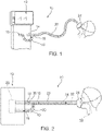
- breathing circuit system 10 forms a breathing circuit shown in FIG. 2 .
- breathing circuit system 10 comprises a ventilator 12 having an inspiratory gas outlet port 14 and an expiratory gas inlet port 16.
- Inspiratory gas outlet port 14 is connected to a manifold 18 which has inspiratory gas and expiratory gas lumens.
- the inspiratory gas lumen has a proximal port that is offset by about 90 degrees from a proximal port of the expiratory gas lumen.
- the inspiratory gas lumen and the expiratory gas lumen have coaxial distal ports.
- proximal end refers to the machine end of the breathing circuit and distal end refers to the patient end.
- the coaxial distal ports of manifold 18 are fluidly coupled to a unilimb breathing tube 22.
- Unilimb breathing tube 22 includes a distal connector that is connected to a gas delivery device 24.
- a face mask is shown as an example of a gas delivery device 24.
- Unilimb breathing tube 22 includes an inner, or inspiratory, tube inside an outer, or expiratory, tube. Both tubes are connected to proximal and distal connectors or to a filter device and the distal connector. Linear expansion of unilimb breathing tube 22 causes both tubes to expand.
- a breathing circuit comprises ventilator 12, which may include a carbon dioxide absorber 28 intermediate an inspiratory gas pathway 30 and an expiratory gas pathway 40. Fresh and recycled gases are supplied via inspiratory gas pathway 30 to the lungs 38 of the patient. Expired gases pass through expiratory gas pathway 40 to return to ventilator 12, where they may be scrubbed and recycled.
- Inspiratory gas pathway 30 includes pathways through inspiratory gas outlet port 14, manifold 18, and an inner tube 32 of unilimb breathing tube 22.
- Expiratory gas pathway 40 includes pathways through an outer tube 34 of unilimb breathing tube 22, manifold 18, and expiratory gas inlet port 16.
- Ventilators can deliver tidal volumes in pediatric unilimb breathing tubes that may be smaller than the deadspace. Additional components may also be included to connect unilimb breathing tube 22 and gas delivery device 24, such as elbows and swivel connectors. These devices change the orientation of gas delivery device 24 relative to unilimb breathing tube 22.
- breathing tubes include single and dual limb devices.
- dual limb devices the inspiratory tube is not inside the expiratory tube.
- An advantage of unilimb breathing tubes is that exhaled gases flow around the inspiratory tube warming the gases therein, which aids in maintaining the patient's temperature at a comfortable level.
- a heat-moisture-exchanger (“HME”) can be placed between the unilimb breathing tube and the gas delivery device to warm and moisturize the inhaled gases.
- the HME may comprise layers of foam and paper impregnated with hygroscopic salts.
- Unilimb breathing tubes may comprise drapable and/or collapsible tubing.
- Drapable tubing comprises corrugations that are not collapsible.
- Collapsible tubing can, advantageously, be longitudinally collapsed to reduce the length of the coaxial breathing tube for storage and transportation, while enabling longitudinal expansion when the unilimb breathing tube is used. Longitudinal expansion can be controlled to provide a desired length.
- An example unilimb breathing tube is described in commonly owned U.S. Patent No. 7,178,521, titled “Adjustable Length Breathing Circuit," issued on February 20, 2007 .
- a breathing circuit system may include a filter device.
- the filter device may be located between the unilimb breathing tube and the gas delivery device or between the unilimb breathing tube and the ventilator. If the filter device is positioned between the unilimb breathing tube and the gas delivery device, the unilimb breathing tube may be protected from contamination and, possibly, reused. If the filter device is positioned between the unilimb breathing tube and the ventilator, at least the expiratory tube should not be reused because expired gases may contaminate it. In both instances the filter device may prevent contamination of the ventilator if the filter is interposed in the expiratory path of the breathing circuit.
- filter devices may be located at both ends of the unilimb breathing tube. However it is preferable to position filter devices at the machine end to reduce clutter near the patient.
- Filter device 50 includes a distal housing 52 coupled to a proximal housing 54.
- Distal housing 52 includes an inspiratory chamber wall 56, an expiratory chamber wall 60, an inner port 58, and an outer port 62.
- Distal housing 52 also includes a peripheral wall 64, and a medial wall 92 extending between inspiratory chamber wall 56 and expiratory chamber wall 60.
- Medial wall 92 ends in walls 94, 98 defining a transverse groove 96 between them (best shown in FIG. 5 ).
- Inspiratory chamber wall 56 together with medial wall 92 form an inspiratory chamber 86.
- Inspiratory chamber wall 56 extends to form an inner wall 68 opposite peripheral wall 64 and forming a groove 66 therebetween.
- Expiratory chamber wall 60 together with medial wall 92 form an expiratory chamber 90.
- Expiratory chamber wall 60 extends to form an inner wall 70 opposite peripheral wall 64 and forming a groove 72 therebetween.
- a filter 100 and a filter 102 are sealingly affixed to filter device 50.
- Proximal housing 54 includes an inspiratory chamber wall 76, an expiratory chamber wall 80, an inner port 78, an outer port 82, and a medial wall 88. Inspiratory chamber wall 76 together with medial wall 88 form an inspiratory chamber 87. Expiratory chamber wall 80 together with medial wall 88 form an expiratory chamber 91. Proximal housing 54 also includes a tongue 84, extending from inspiratory chamber wall 76, expiratory chamber wall 80, and medial wall 88, which forms a tongue and groove joint with grooves 66, 72, and 96 when proximal housing 54 is affixed to distal housing 52, thereby sealing inspiratory chambers 86 and 87 and expiratory chambers 90 and 91.
- Inspiratory chamber wall 76 extends to form an inner wall 69 opposite tongue 84.
- the edge of filter 100 is affixed between inner wall 68 and inner wall 69.
- the edge of filter 102 is affixed between inner wall 70 and an inner wall 71 extending from expiratory chamber wall 80, thereby preventing gas flow except through the filters.
- Substantially all the gases flowing from the ventilator to the patient pass through filter 100 and substantially all the gases flowing from the patient to the ventilator pass through filter 102 when the filter device, the unilimb breathing circuit, and the delivery device are connected properly.
- filter device 50 is integrated with unilimb breathing circuit 20, all the gases entering or leaving filter device 50 from/to the ventilator pass through filter 100 or filter 102.
- filter device 50 is integrated with unilimb breathing circuit 20, all the gases entering or leaving filter device 50 from/to the ventilator pass through filter 100 or filter 102 and the distal connector of unilimb breathing circuit 20.
- Medial walls 88 and 92 divide filter device 50 such that filters 100 and 102 are substantially equal in surface area.
- the chamber sizes can be adapted so that filters 100 and 102 are not equal in size.
- the filters can comprise the same or different filtering media. It may be desirable, for example, to provide a finer inspiratory filter to protect the patient and a less fine filter to protect the ventilator, in which case a larger surface area may be provided for the inspiratory filter to reduce the pressure across it. On the other hand a less fine inspiratory filter may be provided if there is another filter in inspiratory pathway 30.
- a person of skill in the art would be able to change the volumes of the chambers to achieve a desired pressure differential across the filters based on the chosen filter medium and desired filtration capability.
- filter 102 is omitted and the expiratory chambers are reduced in size to reduce the overall size of filter device 50.
- filter 100 is omitted and the inspiratory chambers are reduced in size to reduce the overall size of filter device 50.
- Filter device 120 is similar to filter device 50, except that proximal housing 54 is modified to incorporate the function of a manifold.
- Filter device 120 includes distal housing 52 coupled to a proximal housing 122.
- Proximal housing 122 includes inspiratory chamber wall 76, an expiratory chamber wall 130, inner port 78, and an outer port 132 extending from an expiratory tube 134 connected to expiratory chamber wall 130.
- Distal ports 58, 62 are co-axial.
- the filter device is separable from the breathing tube.
- the breathing tube can be a unilimb tube or a dual limb tube.
- the filter device is connected to a proximal connector of the breathing tube to form the breathing circuit.
- FIGS. 7 and 8 illustrate breathing circuit devices incorporating filter devices 50, 120.
- FIG. 7 shows manifold 18 interposed between ventilator 12 and filter device 50.
- FIG. 8 shows that manifold 18 has been omitted and ventilator 12 is directly connected to filter device 120.
- Unilimb breathing circuit 22 is sealingly bonded with filter devices 50, 120 further reducing the likelihood of leakage. The bond may be formed by ultrasonic or adhesive bonding, for example.
- unilimb breathing circuit 22 may be substituted, in some embodiments, with other breathing tubes known in the art, including dual limb tubes and unilimb tubes in which the diameter of the tube is bifurcated by a membrane to form two lumens therein.
- FIGS. 9 and 10 illustrate another embodiment of a filter device, denoted by numeral 50'.
- Filter device 50' includes features which facilitate ultrasonic bonding of a distal housing 52' to a proximal housing 54'.
- distal housing 52 and proximal housing 54 are identical to distal housing 52' and proximal housing 54'.
- Proximal housing 54' is provided with a collar extending from tongue 66. From the collar a protrusion 140 extends parallel to tongue 84.
- Protrusion 140 is configured to fit into a groove 142 disposed on distal housing 52'.
- ultrasonic energy can be directed to protrusion 140 to ultrasonically bond protrusion 140 and groove 142.
- the tongue and groove joint described with reference with FIG. 50 facilitates assembly by insertion of the tongue into the groove, and creates a press-fit seal, and then the ultrasonic bond provides a fluid seal.
- the combination of the tongue and groove joint and the fluid seal provides a robust seal between the housings.
- the tongue is provided in the proximal housing and the groove is provided in the distal housing. In other embodiments the tongue is provided in the distal housing and the groove is provided in the proximal housing.
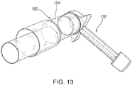
- Test plug 150 comprises an inner port plug 152 and an outer port plug 154.
- Inner port plug 152 is inserted in an inner port 162 of a distal end connector 160 of a breathing tube to test for leakage in the inspiratory pathway during the leakage test.
- the breathing tube may comprise breathing tube 22 having distal connector 160.
- FIG. 12 illustrates inner port plug 152 inserted in inner port 162.
- FIG. 13 illustrates outer port plug 154 inserted in an outer port 164 of distal end connector 160 to test for leakage in the expiratory pathway.
- inner port plug 152 and outer port plug 154 are slightly tapered and configured to press-fit into ports 162, 164 of proximal end connector 160.
- the breathing tube is fluidly coupled to the ventilator.
- the ventilator pressurizes the inspiratory pathway to the test it, with the distal end of the inspiratory pathway plugged by inner port plug 152.
- the ventilator pressurizes the expiratory pathway to the test it, with the distal end of the expiratory pathway plugged by outer port plug 154.
- the ventilator may test the filter device.
- Tighter seals, lower tidal volumes, and more recycling of expired gases reduce the amount of moisture that may escape or be removed from the unilimb breathing tube. Accordingly, increased amounts of moisture can accumulate. Furthermore, it is desirable to keep moisture from entering the ventilator.
- absorbent features to trap moisture may be incorporated in the breathing tube, for example breathing tube 22, or in the filter device, for example filter device 50, 50', and 120.
- absorbent material is provided in the expiratory pathway to absorb moisture.
- the absorbent material comprises superabsorbent gel.
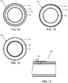
- a tubular insert 174 is disposed between the inner tube 32 and the outer tube 34 of a unilimb breathing tube 170, the tubular insert comprising the absorbent material 172.
- the absorbent material may also be extruded in a layer of a coextruded expiratory and/or inspiratory tube, or laminated or impregnated instead.
- FIG. 15 shows absorbent material 172 extruded in an internal layer of external tube 34 of a unilimb breathing tube 176.
- the absorbent material 16 shows absorbent material 172 extruded in an external layer of inner tube 32 of a unilimb breathing tube 180.
- the absorbent material may also be provided in a breathable packet disposed in the expiratory pathway.
- the absorbent material is provided in the filter device described above, for example in the proximal or distal expiratory chambers. Therefore, the filter device accumulates the moisture.
- the absorbent material may also be incorporated with filter 102.
- the inspiratory tube comprises a moisture permeable membrane.
- the moisture permeable membrane enables passage of moisture from the expiratory pathway to the inspiratory pathway.
- the membrane may be located near the proximal end of the unilimb breathing tube. Passage of the moisture to the inspiratory tube reduces moisture in the expiratory tube and also humidifies the inspiratory pathway gases, which is beneficial for the patient. The moisture also transfers heat, thereby heating the inspiratory pathway gases.
- An inspiratory tubular extension may be provided which comprises the moisture permeable membrane in order to reduce manufacturing complexity.
- the extension may be coupled to the inspiratory tube on one end and to the distal inner port of the filter device or the manifold on the other end.
- the moisture permeable membrane comprises a monolithic membrane configured to draw moisture via diffusion.
- An absorbent material may be provided on one side of the monolithic membrane to provide the moisture, which is then diffused to the inspiratory pathway where it is absorbed by the inspiratory pathway gases.
- Monolithic membranes can comprise, for example, a hydrophilic polyether block amide, which is waterproof while also exhibiting high permeability to moisture vapor. Microporous membranes may also be used.
- Microporous membranes may comprise, for example, solid particles in a polymer film. Tortuous paths are then formed between the particles by stretching the polymer film. Calcium carbonate is a known solid particle used to make polymeric films. A sulfonated tetrafluoroethylene based fluoropolymer-copolymer membrane may also be used.
- a phase change material is provided. Upon activation of the phase change material, it generates heat to warm the inspiratory pathway gases provided to the patient. Activation may occur, for example, by breaking a package to expose the phase change material to oxygen and generate an exothermic reaction.
- a heating wire is provided to heat the inspiratory tube and thereby heat the inspiratory pathway gases provided to the patient.
- the heating wire may be disposed in a wall of the inspiratory tube.
- the heating wire is connected to an electrical energy source, and it heats up due to its electrical resistance.
- a swivel connector comprises a swivel mechanism which can rotate an element with dual ports, one port being longitudinally aligned with the distal connector of the unilimb breathing tube (e.g. straight) and the other port being offset by 90 degrees.
- the swivel connector can thus be connected to a face mask, for example, using the offset port, and to another gas delivery device with the straight port.
- the connector may also comprise two openings, one connected to the straight port and the other to the offset port, and rotating the connector thus connects one or the other port via one or the other openings.
- an integrated circuit 192 (shown in FIG. 17 ) is provided at or near the distal end of the unilimb breathing tube.
- Integrated circuit 192 may be connected to distal connector 160, 190 of the unilimb breathing tube of breathing tube 22.
- a sensing device 194 may be connected to integrated circuit 192. The sensing device may be fluidly coupled to the distal connector, the swivel connector or the gas delivery device to detect a parameter associated with the inspiratory gases.
- Integrated circuit 192 may include a wireless transmitter configured to transmit a value of the parameter.
- the parameter value is transmitted wirelessly to the ventilator, and the ventilator can thus control or adjust the anaesthetic drug volume, the pressure of the inspiratory gases, the temperature of the inspiratory gases, carbon dioxide concentration of expired gases, and any other parameter based on the transmitted parameter value.
- transmission of parameter values reduces the number of tubes by, for example, eliminating the need to connect a gas sampling tube to the breathing circuit.
- measurements obtained near the patient are more beneficial than those obtained remotely, due to time and distance induced variation.
- the sensor may sense, for example, anaesthetic drug concentration, flow rate, pressure, presence of bacteria, temperature, pressure, movement, etc. Any sensor known in the art may be used.
- Integrated circuit 192 may comprise a system-on-a-chip with a processor, analog-to-digital converter, and a wireless transmitter configured to transmit the digital data.
- the sensor may comprise, for example, an accelerometer or gyroscope to measure motion. The sensor may also measure colors to detect a chemical reaction resulting from the presence of bacteria.
- a bacteriocidal threshold may be provided to indicate whether the unilimb breathing tube may be reused. If the value is above the threshold, the device must be discarded.
- the integrated circuit may also provide an alarm signal if the sensed parameter value is outside a safe range. For example, excessive movement may be indicative of patient distress.
- a discontinuity in flow may be indicative of a disconnection in the breathing circuit or a failure of the ventilator.
- a wireless receiver may be incorporated in the ventilator or provided in a separate monitoring device, for example in a portable monitoring device usable during transportation of the patient or in the field.
- a breathing circuit device comprises an expiratory tube providing an expiratory pathway for expired gases from a patient; an inspiratory tube inside the expiratory tube, the inspiratory tube providing an inspiratory pathway for inspired gases to be provided to the patient; a distal connector connected to the expiratory tube and to the inspiratory tube; a proximal connector connected to the expiratory tube and to the inspiratory tube; and an absorbent material configured to absorb moisture from the expired gases, the absorbent material positioned between the distal connector and the proximal connector.
- a breathing circuit device as in example A wherein the absorbent material comprises a superabsorbent polymer.
- the expiratory tube comprises an external layer and an internal layer, and the absorbent material is supported by the internal layer.
- a breathing circuit device as in example A further comprising a tubular sleeve having a diameter larger than the inspiratory tube and smaller than the expiratory tube, the inspiratory tube passing through the tubular sleeve and comprising the absorbent material.
- a breathing circuit device as in example A wherein the absorbent material is attached to an external surface of the inspiratory tube.
- the absorbent material is laminated to the external surface of the inspiratory tube.
- a breathing circuit device as in example A further comprising a filter device including a distal inner port, a proximal inspiratory port, an inspiratory pathway between the distal inspiratory port and the proximal inspiratory port, a distal expiratory port, a proximal expiratory port, an expiratory pathway between the distal expiratory port and the proximal expiratory port, and at least one filter substrate in at least one of the inspiratory pathway and the expiratory pathway.
- the filter device includes a distal housing having a distal inspiratory chamber fluidly coupled to the distal inspiratory port, and a distal expiratory chamber fluidly coupled to the distal expiratory; and a proximal housing attached to the distal housing and having a proximal inspiratory chamber coupled to the proximal inspiratory port, and a proximal expiratory chamber fluidly coupled to the proximal expiratory port, wherein the distal inspiratory chamber is sealingly attached to the proximal inspiratory chamber forming a sealed inspiratory pathway between the distal inspiratory port and the proximal inspiratory port, and the distal expiratory chamber is sealingly attached to the proximal expiratory chamber forming a sealed expiratory pathway between the distal expiratory port and the proximal expiratory port.
- the proximal housing comprises a proximal filter connector comprising the proximal inspiratory port and the proximal expiratory port, wherein the proximal filter connector is removably attachable to the distal connector.
- the proximal inspiratory port is permanently connected to the inspiratory tube
- the proximal expiratory port is permanently connected to the expiratory tube
- the at least one filter substrate comprises a first filter substrate in the inspiratory pathway and a second filter substrate in the expiratory pathway.
- the breathing circuit device further comprises a structural sealing arrangement sealingly connecting the distal inspiratory chamber and the proximal inspiratory chamber, the structural sealing arrangement comprising a wall inserted into a slot, the slot formed in one of the distal housing and the proximal housing, and the wall formed in the other of the distal housing and the proximal housing.
- a dual-chamber filter device comprises a distal housing having an inspiratory chamber and an expiratory chamber; a proximal housing having an inspiratory chamber and an expiratory chamber; an inspiratory filter between the inspiratory chamber of the distal housing and the inspiratory chamber of the proximal housing; wherein the distal housing and the proximal housing are attached, and wherein an inspiratory chamber structural sealing arrangement sealingly couples the proximal and distal inspiratory chambers to form a sealed inspiratory chamber and an expiratory chamber structural sealing arrangement sealingly couples the distal and proximal expiratory chambers to form a sealed expiratory chamber.
- a dual-chamber filter device as in example B further comprising a distal inspiratory port, a distal expiratory port offset by more than 30 degrees from the distal inspiratory port, a proximal inspiratory port, and a proximal expiratory port, wherein the proximal inspiratory port and the proximal expiratory port are substantially coaxial.
- a dual-chamber filter device as in example B further comprising a distal inspiratory port, a distal expiratory port offset by about 90 degrees from the distal inspiratory port, a proximal inspiratory port, and a proximal expiratory port, wherein the proximal inspiratory port and the proximal expiratory port are substantially coaxial.
- a breathing tube comprising an inner tube fluidly coupled to the distal inner port; an outer tube fluidly coupled to the distal outer port, wherein the inner tube is positioned inside the outer tube; and a distal connector connecting a distal end of the inner tube to a distal end of the outer tube.
- the breathing tube of example C wherein the inner tube and the outer tube are permanently affixed to the filter device, further comprising a wireless transmitter in the distal connector of the breathing circuit device.
- a wireless transmitter in the distal connector of the breathing circuit device.
- a sensor configured to detect a characteristic of a gas flowing through the distal connector, wherein the wireless transmitter is configured to transmit a value of the characteristic of the gas.
- the breathing tube of example C further comprising a wireless transmitter in the distal connector of the breathing circuit device.
- a wireless transmitter in the distal connector of the breathing circuit device.
- the wireless transmitter is configured to transmit a value of the characteristic of the gas.
- a breathing tube comprising an inner tube fluidly coupled to the distal inner port; an outer tube fluidly coupled to the distal outer port, wherein the inner tube is positioned inside the outer tube; and a distal connector (160) connecting a distal end of the inner tube to a distal end of the outer tube; further comprising an absorbent material positioned between the inner tube and the outer tube.
- the breathing tube of example D wherein the outer tube comprises an external layer and an internal layer, and the absorbent material is attached to the internal layer.
- the breathing tube of example D wherein the absorbent material is attached to an external surface of the inner tube.
- the breathing tube of example D further comprising a tubular sleeve comprising the absorbent material, wherein the tubular sleeve is positioned intermediate the inner tube and the outer tube, with the inner tube passing through the tubular sleeve.
- the breathing tube of example D wherein the inner tube and the outer tube are permanently affixed to the filter device, further comprising a wireless transmitter in the distal connector of the breathing circuit device.
- a wireless transmitter in the distal connector of the breathing circuit device.
- a sensor configured to detect a characteristic of a gas flowing through the distal connector, wherein the wireless transmitter is configured to transmit a value of the characteristic of the gas.
- the breathing tube of example D further comprising a wireless transmitter in the distal connector of the breathing circuit device.
- a wireless transmitter in the distal connector of the breathing circuit device.
- the wireless transmitter is configured to transmit a value of the characteristic of the gas.
Claims (15)
- Dispositif de circuit respiratoire comprenant :
un dispositif de filtration (50, 50', 120) comprenant :un boîtier distal (52, 52') comprenant une paroi de chambre d'inspiration (56) et une paroi de chambre d'expiration (60), une paroi médiane distale (92) s'étendant entre la paroi de chambre d'inspiration (56) et la paroi de chambre d'expiration (60), un orifice interne distal (58), et un orifice externe distal (62) agencé de manière coaxiale avec ledit orifice interne distal (58) ;un boîtier proximal (54, 54', 122) comprenant une paroi de chambre d'inspiration (76) et une paroi de chambre d'expiration (80), une paroi médiane proximale (88) s'étendant entre la paroi de chambre d'inspiration (76) et la paroi de chambre d'expiration (80), un orifice interne proximal (78), et un orifice externe proximal (82, 132), le boîtier proximal (54, 54', 122) étant fixé de manière étanche au boîtier distal (52, 52'), la paroi de chambre d'inspiration (56) étant jointe à la paroi de chambre d'inspiration (76) et la paroi médiane distale (92) étant jointe à la paroi médiane proximale (88) pour former une voie d'inspiration (73) entre l'orifice interne distal (58) et l'orifice interne proximal (78), et la paroi de chambre d'expiration (60) étant jointe à la paroi de chambre d'expiration (80) pour former, avec la paroi médiane distale (92) et la paroi médiane proximale (88), une voie d'expiration (75) entre l'orifice externe distal (62) et l'orifice externe proximal (82, 132) qui est étanche au fluide par rapport à la voie d'inspiration (73), la voie d'inspiration (73) étant latéralement adjacente à la voie d'expiration (75) ; etun premier filtre (100, 102) dans la voie d'inspiration (73) ou dans la voie d'expiration (75) pour filtrer les gaz s'écoulant à travers la voie d'inspiration (73) ou la voie d'expiration (75). - Dispositif de circuit respiratoire selon la revendication 1, le premier filtre (100, 102) étant fixé de manière étanche entre le boîtier distal (52, 52') et le boîtier proximal (54, 54', 122).
- Dispositif de circuit respiratoire selon la revendication 1, l'orifice externe proximal (132) s'étendant latéralement depuis le boîtier proximal (122).
- Dispositif de circuit respiratoire selon la revendication 3, l'orifice externe proximal (132) s'étendant latéralement depuis le boîtier proximal (122) selon un angle compris entre 60 et 100 degrés par rapport à un axe longitudinal de l'orifice interne proximal (78).
- Dispositif de circuit respiratoire selon la revendication 1, le premier filtre (100) étant positionné pour filtrer les gaz s'écoulant à travers la voie d'inspiration (73) et étant fixé de manière étanche pour filtrer sensiblement 100 % des gaz s'écoulant de l'orifice interne proximal (78) à l'orifice interne distal (58).
- Dispositif de circuit respiratoire selon la revendication 1, le premier filtre (100) étant positionné pour filtrer les gaz s'écoulant à travers la voie d'inspiration (73), comprenant en outre un second filtre (102) fixé de manière étanche entre le boîtier distal (52, 52') et le boîtier proximal (54, 54', 122) pour filtrer les gaz s'écoulant à travers la voie d'expiration (75).
- Dispositif de circuit respiratoire selon l'une quelconque des revendications 1 à 6, comprenant en outre un joint à languette et rainure comprenant une rainure (66, 72, 96) formée dans le boîtier distal ou le boîtier proximal et une languette (84) formée dans l'autre du boîtier distal ou du boîtier proximal, le joint à languette et rainure rendant étanche la voie d'expiration (75) et la voie d'inspiration (73) l'une par rapport à l'autre et par rapport à l'environnement extérieur.
- Dispositif de circuit respiratoire selon la revendication 7, comprenant en outre une saillie circonférentielle (140) formée dans le boîtier distal ou le boîtier proximal et une rainure circonférentielle (142) formée dans l'autre du boîtier distal ou du boîtier proximal, la saillie circonférentielle (140) étant configurée pour s'adapter dans la rainure circonférentielle (142) pendant l'assemblage.
- Dispositif de circuit respiratoire selon la revendication 8, la saillie circonférentielle (140) et la rainure circonférentielle (142) étant disposées à l'extérieur du joint à languette et rainure.
- Dispositif de circuit respiratoire selon la revendication 8, la saillie circonférentielle (140) et la rainure circonférentielle (142) étant configurées pour être liées par ultrasons lors de l'application d'une énergie ultrasonore.
- Dispositif de circuit respiratoire selon la revendication 1, comprenant en outre :un tube interne (32) couplé de manière fluide à l'orifice interne distal ;un tube externe (34) couplé de manière fluide à l'orifice externe distal, le tube interne étant positionné à l'intérieur du tube externe ; etun raccord distal (160, 190) reliant une extrémité distale du tube interne à une extrémité distale du tube externe.
- Dispositif de circuit respiratoire selon la revendication 11, le tube interne (32) et le tube externe (34) étant fixés de manière permanente au dispositif de filtration.
- Dispositif de circuit respiratoire selon la revendication 11, comprenant en outre un matériau absorbant positionné (172) entre le tube interne (32) et le tube externe (34).
- Dispositif de circuit respiratoire selon la revendication 13, le matériau absorbant comprenant un polymère super-absorbant.
- Dispositif de circuit respiratoire selon la revendication 13, comprenant en outre un manchon tubulaire (174) comprenant le matériau absorbant (172), le manchon tubulaire étant positionné entre le tube interne et le tube externe, le tube interne passant à travers le manchon tubulaire.
Applications Claiming Priority (3)
| Application Number | Priority Date | Filing Date | Title |
|---|---|---|---|
| US201562245987P | 2015-10-24 | 2015-10-24 | |
| US201662300758P | 2016-02-26 | 2016-02-26 | |
| PCT/US2016/058528 WO2017070696A1 (fr) | 2015-10-24 | 2016-10-24 | Dispositifs et systèmes de circuit respiratoire |
Publications (3)
| Publication Number | Publication Date |
|---|---|
| EP3365072A1 EP3365072A1 (fr) | 2018-08-29 |
| EP3365072A4 EP3365072A4 (fr) | 2019-10-02 |
| EP3365072B1 true EP3365072B1 (fr) | 2022-10-19 |
Family
ID=58558171
Family Applications (1)
| Application Number | Title | Priority Date | Filing Date |
|---|---|---|---|
| EP16858457.1A Active EP3365072B1 (fr) | 2015-10-24 | 2016-10-24 | Dispositifs et systèmes de circuit respiratoire |
Country Status (3)
| Country | Link |
|---|---|
| US (2) | US10857321B2 (fr) |
| EP (1) | EP3365072B1 (fr) |
| WO (1) | WO2017070696A1 (fr) |
Families Citing this family (10)
| Publication number | Priority date | Publication date | Assignee | Title |
|---|---|---|---|---|
| US10857321B2 (en) * | 2015-10-24 | 2020-12-08 | Ambu A/S | Breathing circuit systems and devices |
| EP3551270B1 (fr) * | 2016-12-09 | 2023-07-19 | Fisher & Paykel Healthcare Limited | Ensemble filtre |
| CN110141751A (zh) * | 2019-05-20 | 2019-08-20 | 河南省健琪医疗器械有限公司 | 呼吸过滤器 |
| WO2021016482A1 (fr) * | 2019-07-24 | 2021-01-28 | Bunnell Incorporated | Ventilateur pulmonaire à filtres interchangeables |
| CN110464960A (zh) * | 2019-08-26 | 2019-11-19 | 江苏海德医学科技股份有限公司 | 湿热交换过滤器 |
| CN111956289B (zh) * | 2020-08-11 | 2022-01-07 | 中国人民解放军空军军医大学 | 一种心内科治疗辅助装置 |
| FR3113604A1 (fr) * | 2020-08-26 | 2022-03-04 | Infiplast | Dispositif de filtration pour circuit respiratoire |
| GB2607347B (en) * | 2021-06-04 | 2024-03-27 | Flexicare Group Ltd | A breathing assembly |
| US11364357B1 (en) * | 2021-09-10 | 2022-06-21 | Casey D. Barton | Pharyngeal respirators |
| US20230173215A1 (en) | 2021-12-08 | 2023-06-08 | Ambu A/S | Medical airway device |
Citations (1)
| Publication number | Priority date | Publication date | Assignee | Title |
|---|---|---|---|---|
| EP0462412A2 (fr) * | 1990-06-18 | 1991-12-27 | Engström Medical Ab | Connecteur en forme de pièce Y pour ventilateur artificiel |
Family Cites Families (92)
| Publication number | Priority date | Publication date | Assignee | Title |
|---|---|---|---|---|
| US3713440A (en) | 1971-01-18 | 1973-01-30 | P Nicholes | Filtration system |
| US3932153A (en) | 1974-02-14 | 1976-01-13 | John Byrns | Nebulizer bacteria filter |
| US3954625A (en) | 1974-09-27 | 1976-05-04 | Plastisonics Company, Inc. | Filter and method of forming same |
| US4148732A (en) | 1977-04-05 | 1979-04-10 | Burrow Clovis E | Bacteria filter unit |
| US4188946A (en) | 1977-10-07 | 1980-02-19 | Rayburn Robert L | Controllable partial rebreathing anesthesia circuit and respiratory assist device |
| US4248219A (en) | 1979-06-20 | 1981-02-03 | Stanley C. Weinrich | Scavenger system for anesthesia circuits |
| US4462397A (en) | 1981-04-03 | 1984-07-31 | Terumo Corporation | Breathing circuit |
| DE3339988A1 (de) | 1983-11-04 | 1985-05-15 | Annedore Kinnle Med. Techn. Zubehör GmbH, 5000 Köln | Anschlusskopf fuer die atemluftversorgung von patienten mit luftstutzen, einem messstutzen und trachealkanuelenanschluss |
| US4593690A (en) | 1984-06-28 | 1986-06-10 | David S. Sheridan | Endotracheal tubes with improved proximal end connector units |
| US4637384A (en) | 1985-02-15 | 1987-01-20 | The Boc Group, Inc. | Coaxial breathing circuit |
| GB8622706D0 (en) | 1986-09-20 | 1986-10-29 | Domnick Hunter Filters Ltd | Filter assembly |
| US4729765A (en) | 1986-12-22 | 1988-03-08 | Eckels John F | Method of using meconium aspirator components |
| US4846167A (en) | 1987-03-30 | 1989-07-11 | Tibbals James R | Anti-disconnect device |
| US4966550A (en) | 1988-04-25 | 1990-10-30 | Privat Richard F | Filter device |
| US4966398A (en) | 1989-02-14 | 1990-10-30 | Buell Industries, Inc. | Fluid conduit coupling |
| GB8911627D0 (en) | 1989-05-19 | 1989-07-05 | Intersurgical Guernsey Ltd | Improvements in filters |
| US5213096A (en) | 1990-06-18 | 1993-05-25 | Gambro Engstrom Ab | Apparatus for connecting a patient to breathing devices, the apparatus including a bacteria filter and gas sampling means |
| US5716210A (en) | 1993-12-29 | 1998-02-10 | Dentsply Research & Development Corp. | Disposable filter for dental handpiece |
| US5694922A (en) | 1994-05-18 | 1997-12-09 | Ballard Medical Products | Swivel tube connections with hermetic seals |
| US5794986A (en) | 1994-09-15 | 1998-08-18 | Infrasonics, Inc. | Semi-disposable ventilator breathing circuit tubing with releasable coupling |
| US6113572A (en) | 1995-05-24 | 2000-09-05 | C. R. Bard, Inc. | Multiple-type catheter connection systems |
| US5901705A (en) | 1996-10-17 | 1999-05-11 | King Systems Corporation | Sleeved filter for a breathing circuit |
| US5722391A (en) | 1996-11-12 | 1998-03-03 | Par Medical, Inc. | Anesthesia tube assembly |
| US5778872A (en) | 1996-11-18 | 1998-07-14 | Medlis, Inc. | Artificial ventilation system and methods of controlling carbon dioxide rebreathing |
| US6439231B1 (en) | 1996-11-18 | 2002-08-27 | Medlis Corp. | Artificial ventilation systems and components thereof, and methods for providing, assembling and utilizing same |
| US6003511A (en) | 1996-11-18 | 1999-12-21 | Medlis Corp. | Respiratory circuit terminal for a unilimb respiratory device |
| US5766468A (en) | 1997-01-06 | 1998-06-16 | Baldwin Filters, Inc. | Dual media primary/secondary fuel filter |
| US6231085B1 (en) | 1997-04-21 | 2001-05-15 | Irrigation Development Company | Tubing coupling and hose end combination, and related method |
| US6209541B1 (en) * | 1998-02-25 | 2001-04-03 | Sims Portex Inc. | Hydrophobic electrostatic breathing filters, and methods of manufacturing the same |
| US6079410A (en) | 1998-07-06 | 2000-06-27 | Q.D.S. Injection Molding, Inc. | Collapsible snorkel |
| IT1310042B1 (it) | 1999-11-26 | 2002-02-05 | Pier Luigi Delvigo | Filtro senza spazio morto |
| EP1129743B1 (fr) | 2000-03-02 | 2006-05-10 | Fisher & Paykel Healthcare Limited | Filtre |
| US7559324B2 (en) | 2000-06-21 | 2009-07-14 | Fisher & Paykel Healthcare Limited | Conduit with heated wick |
| US6641177B1 (en) | 2000-08-25 | 2003-11-04 | Precision Design Concepts, Llc | Quick connect tube coupling and method of assembling the same |
| DE10134725A1 (de) | 2001-07-17 | 2003-02-06 | Weinmann G Geraete Med | Vorrichtung zur Filterung von Atemluft |
| DE60212158T2 (de) | 2001-09-24 | 2007-04-19 | Atsuo F. Palos Verdes Peninsula Fukunaga | Atemkreisläufe mit unkonventionellen atemleitungen und systeme und verfahren zur optimierung der verwendung von frischgasen |
| US7717109B2 (en) | 2001-09-24 | 2010-05-18 | F-Concepts Llc | Breathing systems with post-inspiratory valve fresh gas flow input, components for implementing same, and methods of use |
| US7261105B2 (en) | 2001-09-24 | 2007-08-28 | F-Concepts Llc | Breathing circuits having unconventional respiratory conduits and systems and methods for optimizing utilization of fresh gases |
| US7163531B2 (en) | 2002-08-19 | 2007-01-16 | Baxter International, Inc. | User-friendly catheter connection adapters for optimized connection to multiple lumen catheters |
| US6896688B2 (en) | 2002-09-12 | 2005-05-24 | Edrich Health Technologies, Inc. | Prosthetic vascular graft connector |
| US7347203B2 (en) | 2002-09-16 | 2008-03-25 | Thayer Medical Corporation | Heat and moisture filter exchanger and method |
| US7191782B2 (en) | 2003-05-06 | 2007-03-20 | Kimberly-Clark Worldwide, Inc. | Respiratory suction catheter apparatus configured for releasable attachment with an artificial airway structure |
| US20050178381A1 (en) | 2003-05-13 | 2005-08-18 | Roger Daugherty | Apparatus and method for humidification of inspired gases |
| US7044506B2 (en) | 2003-08-07 | 2006-05-16 | Xiamen Lota International Co., Ltd. | Quick connector assembly |
| US20050082828A1 (en) | 2003-09-12 | 2005-04-21 | Wicks Jeffrey C. | Releasable connection assembly for joining tubing sections |
| US7178521B2 (en) | 2004-01-09 | 2007-02-20 | King Systems Corporation | Adjustable length breathing circuit |
| US20050188990A1 (en) * | 2004-02-12 | 2005-09-01 | Fukunaga Atsuo F. | Multifunctional integrated filter and breathing conduit |
| US7578803B2 (en) | 2004-03-18 | 2009-08-25 | C. R. Bard, Inc. | Multifunction adaptor for an open-ended catheter |
| US7201168B2 (en) | 2004-04-14 | 2007-04-10 | King Systems Corporation | Non-tracheal ventilation tube |
| JP5102023B2 (ja) | 2004-06-29 | 2012-12-19 | シー アール バード インコーポレイテッド | 胃瘻造設チューブとの流体連通を行うための方法およびシステム |
| US7294263B2 (en) | 2005-02-09 | 2007-11-13 | Gm Global Technology Operations, Inc. | Dual transmission filter design |
| US7753051B2 (en) | 2005-03-18 | 2010-07-13 | King Systems Corporation | Face mask strap system |
| US8297318B2 (en) | 2005-05-21 | 2012-10-30 | Mark Johnson | Check valve |
| US20070012317A1 (en) | 2005-07-08 | 2007-01-18 | Flagler Robert W | Medical device tube |
| US7527300B2 (en) | 2005-08-24 | 2009-05-05 | Beckman Coulter, Inc. | Flexible tubing connector |
| EP1933733A2 (fr) | 2005-10-14 | 2008-06-25 | Applied Medical Resources Corporation | Orifice d'acces chirurgical |
| IL178438A0 (en) | 2006-10-04 | 2007-02-11 | Netafim Ltd | Coupling |
| US8297661B2 (en) | 2007-05-15 | 2012-10-30 | Emd Millipore Corporation | Connector for flexible tubing |
| TWI354648B (en) | 2007-06-22 | 2011-12-21 | Quickly assemblable structure of molecular sieves | |
| AU2008318210B2 (en) | 2007-10-30 | 2011-07-28 | Medela Holding Ag | Device for connecting a suction tube |
| US7862090B1 (en) | 2007-12-28 | 2011-01-04 | R.L. Hudson & Company | Plug-in fitting for direct connection to housing |
| CA2716995C (fr) | 2008-03-05 | 2014-11-04 | Hemosphere, Inc. | Systeme d'acces vasculaire |
| US8967139B2 (en) | 2008-04-29 | 2015-03-03 | Carefusion Corporation | Respiratory connector and arrangement for connecting an inspiratory tube and an expiratory tube to a medical apparatus |
| US8235426B2 (en) | 2008-07-03 | 2012-08-07 | Nordson Corporation | Latch assembly for joining two conduits |
| EP2158935B1 (fr) | 2008-08-29 | 2014-07-16 | Dräger Medical GmbH | Connecteur à fiche pour tuyaux médicaux |
| WO2010036839A2 (fr) | 2008-09-26 | 2010-04-01 | Oriel Therapeutics, Inc. | Inhaleurs avec disques de voie aérienne munis de canaux de voie aérienne discrets ainsi que disques et procédés associés |
| US20100152748A1 (en) | 2008-12-12 | 2010-06-17 | E-Pacing, Inc. | Devices, Systems, and Methods Providing Body Lumen Access |
| US8485187B2 (en) | 2009-04-28 | 2013-07-16 | Dynasthetics, Llc | System, method and apparatus for removal of volatile anesthetics for malignant hyperthermia |
| US9388929B2 (en) | 2009-12-09 | 2016-07-12 | Nordson Corporation | Male bayonet connector |
| US8800552B2 (en) | 2009-12-15 | 2014-08-12 | Covidien Lp | Tracheal tube and tube extension |
| US8622058B2 (en) | 2010-02-22 | 2014-01-07 | Respan Products, Inc. | Medical air tubing connection system |
| EP2481966A1 (fr) | 2011-02-01 | 2012-08-01 | Uponor Innovation AB | Bague de serrage |
| DE102011014018B4 (de) | 2011-03-15 | 2016-10-13 | Drägerwerk AG & Co. KGaA | Vorrichtung zum Filtern von Atemgas |
| GB2500061B (en) | 2012-03-09 | 2018-11-28 | Intersurgical Ag | Connector for respiratory ducts |
| CN116764058A (zh) | 2012-07-27 | 2023-09-19 | 瑞思迈私人有限公司 | 患者接口与用于制造它的方法 |
| US9108008B2 (en) | 2012-12-14 | 2015-08-18 | S & T Medical Technologies, Inc. | Bubble continuous positive airway pressure device |
| WO2014129912A1 (fr) | 2013-02-20 | 2014-08-28 | Fisher & Paykel Healthcare Limited | Raccord pour raccordements à tailles multiples |
| US9523453B2 (en) | 2013-03-20 | 2016-12-20 | Miniature Precision Components, Inc. | Locking quick connect assembly |
| DE102015200613A1 (de) | 2015-01-16 | 2016-07-21 | B. Braun Melsungen Ag | Verbindungsvorrichtung für ein medizinisches Fluidleitungssystem |
| US11446462B2 (en) | 2015-03-31 | 2022-09-20 | Fisher & Paykel Healthcare Limited | Apparatus for use in a respiratory support system |
| CN204798549U (zh) | 2015-05-08 | 2015-11-25 | 深圳安维森实业有限公司 | 含多功能转接头的中分管组件 |
| US10758694B2 (en) | 2015-07-09 | 2020-09-01 | Hoyt Medical LLC | Systems and methods for treating an airway using a tapered adapter device |
| KR102650815B1 (ko) | 2015-09-04 | 2024-03-26 | 피셔 앤 페이켈 핼스케어 리미티드 | 도관용 커넥터들 |
| US11247007B2 (en) | 2015-10-16 | 2022-02-15 | Metran Co., Ltd. | Silencer and artificial ventilator |
| US10857321B2 (en) * | 2015-10-24 | 2020-12-08 | Ambu A/S | Breathing circuit systems and devices |
| US11235121B2 (en) | 2015-11-06 | 2022-02-01 | Fisher & Paykel Healthcare Limited | Apparatus for use in a respiratory support system |
| US9759359B2 (en) | 2016-01-26 | 2017-09-12 | Tectran Mfg. Inc. | Grip and fitting assemblies and kits utilizing the same |
| EP3551270B1 (fr) | 2016-12-09 | 2023-07-19 | Fisher & Paykel Healthcare Limited | Ensemble filtre |
| US10330209B2 (en) | 2017-01-26 | 2019-06-25 | Fresenius Medical Care Holdings, Inc. | Check valve and method of forming a check valve |
| WO2018145100A1 (fr) | 2017-02-06 | 2018-08-09 | Intuitive Surgical Operations, Inc. | Systèmes et méthodes d'accouplement de composants d'un système médical |
| BR112023002376A2 (pt) | 2020-08-10 | 2023-03-21 | Vayu Global Health Innovations Llc | Alojamento de filtro de gás de respiração médico |
| FR3113604A1 (fr) | 2020-08-26 | 2022-03-04 | Infiplast | Dispositif de filtration pour circuit respiratoire |
-
2016
- 2016-10-24 US US15/770,455 patent/US10857321B2/en active Active
- 2016-10-24 WO PCT/US2016/058528 patent/WO2017070696A1/fr active Application Filing
- 2016-10-24 EP EP16858457.1A patent/EP3365072B1/fr active Active
-
2020
- 2020-11-02 US US17/087,510 patent/US11826513B2/en active Active
Patent Citations (1)
| Publication number | Priority date | Publication date | Assignee | Title |
|---|---|---|---|---|
| EP0462412A2 (fr) * | 1990-06-18 | 1991-12-27 | Engström Medical Ab | Connecteur en forme de pièce Y pour ventilateur artificiel |
Also Published As
| Publication number | Publication date |
|---|---|
| US20210069450A1 (en) | 2021-03-11 |
| US20180311459A1 (en) | 2018-11-01 |
| EP3365072A1 (fr) | 2018-08-29 |
| WO2017070696A1 (fr) | 2017-04-27 |
| EP3365072A4 (fr) | 2019-10-02 |
| US10857321B2 (en) | 2020-12-08 |
| US11826513B2 (en) | 2023-11-28 |
Similar Documents
| Publication | Publication Date | Title |
|---|---|---|
| US11826513B2 (en) | Breathing circuit systems and devices | |
| US4336798A (en) | Medical corrugated respiratory tube | |
| JP7464659B2 (ja) | フィルターアセンブリ | |
| EP3277357B1 (fr) | Systèmes de transfert de vapeur à proximité du patient pour thérapie respiratoire | |
| US7069928B1 (en) | Heat-moisture exchanger with aerosol by-pass | |
| US8561606B2 (en) | Heat and moisture exchange unit | |
| JP5734842B2 (ja) | 人工気道及び該人工気道を備えた呼吸回路 | |
| US6733556B1 (en) | Antibacterial/antiviral filtering device for ventilation systems | |
| JP5870380B2 (ja) | 連結システム | |
| ES2895414T3 (es) | Sistema para evitar la contaminación cruzada en los sistemas de generación de flujo | |
| US9919124B2 (en) | Delivery adaptor for ventilation system | |
| JP2009544979A (ja) | モジュラー・サイドストリーム・ガス・サンプリング・アセンブリ | |
| EP2869880B1 (fr) | Humidificateur compact | |
| CN107427652A (zh) | 用于湿度控制的系统和方法 | |
| US20140330154A1 (en) | Breathing mask for ventilating a patient and gas analyzer for respiratory gas measurement | |
| EP3079746A2 (fr) | Dispositif d'échange thermo-hydrique de filtre | |
| EP1083954B1 (fr) | Ensemble humidificateur | |
| EP2153859B1 (fr) | Système de ventilation médicale | |
| US10456549B2 (en) | Respiration system and connector system therefor for reducing contaminations | |
| CN104474617A (zh) | 一种热湿交换器 | |
| GB2473443A (en) | Oxygen therapy apparatus | |
| TW201125603A (en) | Transmission tube with temperature-sensing/color-changing piece |
Legal Events
| Date | Code | Title | Description |
|---|---|---|---|
| STAA | Information on the status of an ep patent application or granted ep patent |
Free format text: STATUS: THE INTERNATIONAL PUBLICATION HAS BEEN MADE |
|
| PUAI | Public reference made under article 153(3) epc to a published international application that has entered the european phase |
Free format text: ORIGINAL CODE: 0009012 |
|
| STAA | Information on the status of an ep patent application or granted ep patent |
Free format text: STATUS: REQUEST FOR EXAMINATION WAS MADE |
|
| 17P | Request for examination filed |
Effective date: 20180518 |
|
| AK | Designated contracting states |
Kind code of ref document: A1 Designated state(s): AL AT BE BG CH CY CZ DE DK EE ES FI FR GB GR HR HU IE IS IT LI LT LU LV MC MK MT NL NO PL PT RO RS SE SI SK SM TR |
|
| AX | Request for extension of the european patent |
Extension state: BA ME |
|
| DAV | Request for validation of the european patent (deleted) | ||
| DAX | Request for extension of the european patent (deleted) | ||
| A4 | Supplementary search report drawn up and despatched |
Effective date: 20190903 |
|
| RIC1 | Information provided on ipc code assigned before grant |
Ipc: A61M 16/22 20060101ALI20190828BHEP Ipc: A61M 16/08 20060101ALI20190828BHEP Ipc: A61M 16/00 20060101ALI20190828BHEP Ipc: A61M 16/10 20060101ALI20190828BHEP Ipc: A62B 7/10 20060101AFI20190828BHEP |
|
| STAA | Information on the status of an ep patent application or granted ep patent |
Free format text: STATUS: EXAMINATION IS IN PROGRESS |
|
| 17Q | First examination report despatched |
Effective date: 20210504 |
|
| STAA | Information on the status of an ep patent application or granted ep patent |
Free format text: STATUS: EXAMINATION IS IN PROGRESS |
|
| GRAP | Despatch of communication of intention to grant a patent |
Free format text: ORIGINAL CODE: EPIDOSNIGR1 |
|
| STAA | Information on the status of an ep patent application or granted ep patent |
Free format text: STATUS: GRANT OF PATENT IS INTENDED |
|
| INTG | Intention to grant announced |
Effective date: 20220609 |
|
| RIN1 | Information on inventor provided before grant (corrected) |
Inventor name: KOCH, JAKOB Inventor name: HEAVIN, KLEVE Inventor name: GERSTER, BRIAN Inventor name: REYNOLDS, NATASHA Inventor name: YEH, YUN SIUNG TONY Inventor name: MCGRAIL, THOMAS W. Inventor name: ROSEBROCK, CHARLES Inventor name: COLEMAN, PATRICK Inventor name: WINKLER, KEVIN |
|
| GRAS | Grant fee paid |
Free format text: ORIGINAL CODE: EPIDOSNIGR3 |
|
| GRAA | (expected) grant |
Free format text: ORIGINAL CODE: 0009210 |
|
| STAA | Information on the status of an ep patent application or granted ep patent |
Free format text: STATUS: THE PATENT HAS BEEN GRANTED |
|
| AK | Designated contracting states |
Kind code of ref document: B1 Designated state(s): AL AT BE BG CH CY CZ DE DK EE ES FI FR GB GR HR HU IE IS IT LI LT LU LV MC MK MT NL NO PL PT RO RS SE SI SK SM TR |
|
| REG | Reference to a national code |
Ref country code: GB Ref legal event code: FG4D |
|
| REG | Reference to a national code |
Ref country code: CH Ref legal event code: EP |
|
| REG | Reference to a national code |
Ref country code: IE Ref legal event code: FG4D |
|
| REG | Reference to a national code |
Ref country code: DE Ref legal event code: R096 Ref document number: 602016075796 Country of ref document: DE |
|
| REG | Reference to a national code |
Ref country code: AT Ref legal event code: REF Ref document number: 1525207 Country of ref document: AT Kind code of ref document: T Effective date: 20221115 |
|
| REG | Reference to a national code |
Ref country code: LT Ref legal event code: MG9D |
|
| REG | Reference to a national code |
Ref country code: NL Ref legal event code: MP Effective date: 20221019 |
|
| REG | Reference to a national code |
Ref country code: AT Ref legal event code: MK05 Ref document number: 1525207 Country of ref document: AT Kind code of ref document: T Effective date: 20221019 |
|
| PG25 | Lapsed in a contracting state [announced via postgrant information from national office to epo] |
Ref country code: NL Free format text: LAPSE BECAUSE OF FAILURE TO SUBMIT A TRANSLATION OF THE DESCRIPTION OR TO PAY THE FEE WITHIN THE PRESCRIBED TIME-LIMIT Effective date: 20221019 |
|
| PG25 | Lapsed in a contracting state [announced via postgrant information from national office to epo] |
Ref country code: SE Free format text: LAPSE BECAUSE OF FAILURE TO SUBMIT A TRANSLATION OF THE DESCRIPTION OR TO PAY THE FEE WITHIN THE PRESCRIBED TIME-LIMIT Effective date: 20221019 Ref country code: PT Free format text: LAPSE BECAUSE OF FAILURE TO SUBMIT A TRANSLATION OF THE DESCRIPTION OR TO PAY THE FEE WITHIN THE PRESCRIBED TIME-LIMIT Effective date: 20230220 Ref country code: NO Free format text: LAPSE BECAUSE OF FAILURE TO SUBMIT A TRANSLATION OF THE DESCRIPTION OR TO PAY THE FEE WITHIN THE PRESCRIBED TIME-LIMIT Effective date: 20230119 Ref country code: LT Free format text: LAPSE BECAUSE OF FAILURE TO SUBMIT A TRANSLATION OF THE DESCRIPTION OR TO PAY THE FEE WITHIN THE PRESCRIBED TIME-LIMIT Effective date: 20221019 Ref country code: FI Free format text: LAPSE BECAUSE OF FAILURE TO SUBMIT A TRANSLATION OF THE DESCRIPTION OR TO PAY THE FEE WITHIN THE PRESCRIBED TIME-LIMIT Effective date: 20221019 Ref country code: ES Free format text: LAPSE BECAUSE OF FAILURE TO SUBMIT A TRANSLATION OF THE DESCRIPTION OR TO PAY THE FEE WITHIN THE PRESCRIBED TIME-LIMIT Effective date: 20221019 Ref country code: AT Free format text: LAPSE BECAUSE OF FAILURE TO SUBMIT A TRANSLATION OF THE DESCRIPTION OR TO PAY THE FEE WITHIN THE PRESCRIBED TIME-LIMIT Effective date: 20221019 |
|
| PG25 | Lapsed in a contracting state [announced via postgrant information from national office to epo] |
Ref country code: RS Free format text: LAPSE BECAUSE OF FAILURE TO SUBMIT A TRANSLATION OF THE DESCRIPTION OR TO PAY THE FEE WITHIN THE PRESCRIBED TIME-LIMIT Effective date: 20221019 Ref country code: PL Free format text: LAPSE BECAUSE OF FAILURE TO SUBMIT A TRANSLATION OF THE DESCRIPTION OR TO PAY THE FEE WITHIN THE PRESCRIBED TIME-LIMIT Effective date: 20221019 Ref country code: LV Free format text: LAPSE BECAUSE OF FAILURE TO SUBMIT A TRANSLATION OF THE DESCRIPTION OR TO PAY THE FEE WITHIN THE PRESCRIBED TIME-LIMIT Effective date: 20221019 Ref country code: IS Free format text: LAPSE BECAUSE OF FAILURE TO SUBMIT A TRANSLATION OF THE DESCRIPTION OR TO PAY THE FEE WITHIN THE PRESCRIBED TIME-LIMIT Effective date: 20230219 Ref country code: HR Free format text: LAPSE BECAUSE OF FAILURE TO SUBMIT A TRANSLATION OF THE DESCRIPTION OR TO PAY THE FEE WITHIN THE PRESCRIBED TIME-LIMIT Effective date: 20221019 Ref country code: GR Free format text: LAPSE BECAUSE OF FAILURE TO SUBMIT A TRANSLATION OF THE DESCRIPTION OR TO PAY THE FEE WITHIN THE PRESCRIBED TIME-LIMIT Effective date: 20230120 |
|
| REG | Reference to a national code |
Ref country code: CH Ref legal event code: PL |
|
| REG | Reference to a national code |
Ref country code: BE Ref legal event code: MM Effective date: 20221031 |
|
| PG25 | Lapsed in a contracting state [announced via postgrant information from national office to epo] |
Ref country code: LU Free format text: LAPSE BECAUSE OF NON-PAYMENT OF DUE FEES Effective date: 20221024 |
|
| REG | Reference to a national code |
Ref country code: DE Ref legal event code: R097 Ref document number: 602016075796 Country of ref document: DE |
|
| PG25 | Lapsed in a contracting state [announced via postgrant information from national office to epo] |
Ref country code: SM Free format text: LAPSE BECAUSE OF FAILURE TO SUBMIT A TRANSLATION OF THE DESCRIPTION OR TO PAY THE FEE WITHIN THE PRESCRIBED TIME-LIMIT Effective date: 20221019 Ref country code: RO Free format text: LAPSE BECAUSE OF FAILURE TO SUBMIT A TRANSLATION OF THE DESCRIPTION OR TO PAY THE FEE WITHIN THE PRESCRIBED TIME-LIMIT Effective date: 20221019 Ref country code: MC Free format text: LAPSE BECAUSE OF FAILURE TO SUBMIT A TRANSLATION OF THE DESCRIPTION OR TO PAY THE FEE WITHIN THE PRESCRIBED TIME-LIMIT Effective date: 20221019 Ref country code: LI Free format text: LAPSE BECAUSE OF NON-PAYMENT OF DUE FEES Effective date: 20221031 Ref country code: EE Free format text: LAPSE BECAUSE OF FAILURE TO SUBMIT A TRANSLATION OF THE DESCRIPTION OR TO PAY THE FEE WITHIN THE PRESCRIBED TIME-LIMIT Effective date: 20221019 Ref country code: DK Free format text: LAPSE BECAUSE OF FAILURE TO SUBMIT A TRANSLATION OF THE DESCRIPTION OR TO PAY THE FEE WITHIN THE PRESCRIBED TIME-LIMIT Effective date: 20221019 Ref country code: CZ Free format text: LAPSE BECAUSE OF FAILURE TO SUBMIT A TRANSLATION OF THE DESCRIPTION OR TO PAY THE FEE WITHIN THE PRESCRIBED TIME-LIMIT Effective date: 20221019 Ref country code: CH Free format text: LAPSE BECAUSE OF NON-PAYMENT OF DUE FEES Effective date: 20221031 |
|
| PLBE | No opposition filed within time limit |
Free format text: ORIGINAL CODE: 0009261 |
|
| STAA | Information on the status of an ep patent application or granted ep patent |
Free format text: STATUS: NO OPPOSITION FILED WITHIN TIME LIMIT |
|
| PG25 | Lapsed in a contracting state [announced via postgrant information from national office to epo] |
Ref country code: SK Free format text: LAPSE BECAUSE OF FAILURE TO SUBMIT A TRANSLATION OF THE DESCRIPTION OR TO PAY THE FEE WITHIN THE PRESCRIBED TIME-LIMIT Effective date: 20221019 Ref country code: AL Free format text: LAPSE BECAUSE OF FAILURE TO SUBMIT A TRANSLATION OF THE DESCRIPTION OR TO PAY THE FEE WITHIN THE PRESCRIBED TIME-LIMIT Effective date: 20221019 |
|
| 26N | No opposition filed |
Effective date: 20230720 |
|
| PG25 | Lapsed in a contracting state [announced via postgrant information from national office to epo] |
Ref country code: BE Free format text: LAPSE BECAUSE OF NON-PAYMENT OF DUE FEES Effective date: 20221031 |
|
| PG25 | Lapsed in a contracting state [announced via postgrant information from national office to epo] |
Ref country code: IE Free format text: LAPSE BECAUSE OF NON-PAYMENT OF DUE FEES Effective date: 20221024 |
|
| PGFP | Annual fee paid to national office [announced via postgrant information from national office to epo] |
Ref country code: GB Payment date: 20230914 Year of fee payment: 8 |
|
| PG25 | Lapsed in a contracting state [announced via postgrant information from national office to epo] |
Ref country code: SI Free format text: LAPSE BECAUSE OF FAILURE TO SUBMIT A TRANSLATION OF THE DESCRIPTION OR TO PAY THE FEE WITHIN THE PRESCRIBED TIME-LIMIT Effective date: 20221019 |
|
| PGFP | Annual fee paid to national office [announced via postgrant information from national office to epo] |
Ref country code: FR Payment date: 20230914 Year of fee payment: 8 |
|
| PGFP | Annual fee paid to national office [announced via postgrant information from national office to epo] |
Ref country code: DE Payment date: 20230918 Year of fee payment: 8 |
|
| PG25 | Lapsed in a contracting state [announced via postgrant information from national office to epo] |
Ref country code: HU Free format text: LAPSE BECAUSE OF FAILURE TO SUBMIT A TRANSLATION OF THE DESCRIPTION OR TO PAY THE FEE WITHIN THE PRESCRIBED TIME-LIMIT; INVALID AB INITIO Effective date: 20161024 |