EP3364564A1 - Optical communication system for vehicles - Google Patents
Optical communication system for vehicles Download PDFInfo
- Publication number
- EP3364564A1 EP3364564A1 EP18156171.3A EP18156171A EP3364564A1 EP 3364564 A1 EP3364564 A1 EP 3364564A1 EP 18156171 A EP18156171 A EP 18156171A EP 3364564 A1 EP3364564 A1 EP 3364564A1
- Authority
- EP
- European Patent Office
- Prior art keywords
- light beam
- polarized
- communication device
- polarized light
- transmission system
- Prior art date
- Legal status (The legal status is an assumption and is not a legal conclusion. Google has not performed a legal analysis and makes no representation as to the accuracy of the status listed.)
- Granted
Links
Images
Classifications
-
- H—ELECTRICITY
- H04—ELECTRIC COMMUNICATION TECHNIQUE
- H04B—TRANSMISSION
- H04B10/00—Transmission systems employing electromagnetic waves other than radio-waves, e.g. infrared, visible or ultraviolet light, or employing corpuscular radiation, e.g. quantum communication
- H04B10/11—Arrangements specific to free-space transmission, i.e. transmission through air or vacuum
- H04B10/114—Indoor or close-range type systems
- H04B10/1143—Bidirectional transmission
-
- B—PERFORMING OPERATIONS; TRANSPORTING
- B60—VEHICLES IN GENERAL
- B60Q—ARRANGEMENT OF SIGNALLING OR LIGHTING DEVICES, THE MOUNTING OR SUPPORTING THEREOF OR CIRCUITS THEREFOR, FOR VEHICLES IN GENERAL
- B60Q1/00—Arrangement of optical signalling or lighting devices, the mounting or supporting thereof or circuits therefor
- B60Q1/26—Arrangement of optical signalling or lighting devices, the mounting or supporting thereof or circuits therefor the devices being primarily intended to indicate the vehicle, or parts thereof, or to give signals, to other traffic
- B60Q1/34—Arrangement of optical signalling or lighting devices, the mounting or supporting thereof or circuits therefor the devices being primarily intended to indicate the vehicle, or parts thereof, or to give signals, to other traffic for indicating change of drive direction
-
- B—PERFORMING OPERATIONS; TRANSPORTING
- B60—VEHICLES IN GENERAL
- B60Q—ARRANGEMENT OF SIGNALLING OR LIGHTING DEVICES, THE MOUNTING OR SUPPORTING THEREOF OR CIRCUITS THEREFOR, FOR VEHICLES IN GENERAL
- B60Q1/00—Arrangement of optical signalling or lighting devices, the mounting or supporting thereof or circuits therefor
- B60Q1/26—Arrangement of optical signalling or lighting devices, the mounting or supporting thereof or circuits therefor the devices being primarily intended to indicate the vehicle, or parts thereof, or to give signals, to other traffic
- B60Q1/44—Arrangement of optical signalling or lighting devices, the mounting or supporting thereof or circuits therefor the devices being primarily intended to indicate the vehicle, or parts thereof, or to give signals, to other traffic for indicating braking action or preparation for braking, e.g. by detection of the foot approaching the brake pedal
-
- G—PHYSICS
- G02—OPTICS
- G02B—OPTICAL ELEMENTS, SYSTEMS OR APPARATUS
- G02B27/00—Optical systems or apparatus not provided for by any of the groups G02B1/00 - G02B26/00, G02B30/00
- G02B27/28—Optical systems or apparatus not provided for by any of the groups G02B1/00 - G02B26/00, G02B30/00 for polarising
- G02B27/283—Optical systems or apparatus not provided for by any of the groups G02B1/00 - G02B26/00, G02B30/00 for polarising used for beam splitting or combining
-
- G—PHYSICS
- G08—SIGNALLING
- G08G—TRAFFIC CONTROL SYSTEMS
- G08G1/00—Traffic control systems for road vehicles
- G08G1/09—Arrangements for giving variable traffic instructions
- G08G1/091—Traffic information broadcasting
- G08G1/092—Coding or decoding of the information
-
- G—PHYSICS
- G08—SIGNALLING
- G08G—TRAFFIC CONTROL SYSTEMS
- G08G1/00—Traffic control systems for road vehicles
- G08G1/09—Arrangements for giving variable traffic instructions
- G08G1/091—Traffic information broadcasting
- G08G1/094—Hardware aspects; Signal processing or signal properties, e.g. frequency bands
-
- G—PHYSICS
- G08—SIGNALLING
- G08G—TRAFFIC CONTROL SYSTEMS
- G08G1/00—Traffic control systems for road vehicles
- G08G1/09—Arrangements for giving variable traffic instructions
- G08G1/0962—Arrangements for giving variable traffic instructions having an indicator mounted inside the vehicle, e.g. giving voice messages
- G08G1/0967—Systems involving transmission of highway information, e.g. weather, speed limits
- G08G1/096766—Systems involving transmission of highway information, e.g. weather, speed limits where the system is characterised by the origin of the information transmission
- G08G1/096791—Systems involving transmission of highway information, e.g. weather, speed limits where the system is characterised by the origin of the information transmission where the origin of the information is another vehicle
-
- H—ELECTRICITY
- H04—ELECTRIC COMMUNICATION TECHNIQUE
- H04B—TRANSMISSION
- H04B10/00—Transmission systems employing electromagnetic waves other than radio-waves, e.g. infrared, visible or ultraviolet light, or employing corpuscular radiation, e.g. quantum communication
- H04B10/11—Arrangements specific to free-space transmission, i.e. transmission through air or vacuum
- H04B10/114—Indoor or close-range type systems
- H04B10/116—Visible light communication
-
- G—PHYSICS
- G08—SIGNALLING
- G08G—TRAFFIC CONTROL SYSTEMS
- G08G1/00—Traffic control systems for road vehicles
- G08G1/09—Arrangements for giving variable traffic instructions
- G08G1/0962—Arrangements for giving variable traffic instructions having an indicator mounted inside the vehicle, e.g. giving voice messages
- G08G1/0967—Systems involving transmission of highway information, e.g. weather, speed limits
- G08G1/096708—Systems involving transmission of highway information, e.g. weather, speed limits where the received information might be used to generate an automatic action on the vehicle control
Landscapes
- Engineering & Computer Science (AREA)
- Physics & Mathematics (AREA)
- Signal Processing (AREA)
- General Physics & Mathematics (AREA)
- Electromagnetism (AREA)
- Computer Networks & Wireless Communication (AREA)
- Mechanical Engineering (AREA)
- Multimedia (AREA)
- Life Sciences & Earth Sciences (AREA)
- Atmospheric Sciences (AREA)
- Optics & Photonics (AREA)
- Optical Communication System (AREA)
- Lighting Device Outwards From Vehicle And Optical Signal (AREA)
Abstract
L'invention concerne un dispositif de communication, notamment pour véhicules automobiles, comprenant un système d'émission (1,) muni d'une source lumineuse (2) apte à émettre un faisceau de lumière initial (3), le système d'émission (1) étant configuré pour générer un premier faisceau de lumière polarisée (4) selon une première direction (7) à partir du faisceau de lumière initial (3), le système d'émission (1) comportant en outre un modulateur (11) de la direction de polarisation du premier faisceau de lumière polarisée (4) de manière à transmettre des informations, le dispositif comprenant en outre un système de réception configuré pour détecter ledit premier faisceau de lumière polarisée (4) lorsqu'il est polarisé selon ladite première direction (7) et à transmettre lesdites informations.

Description
La présente invention concerne un dispositif de communication, notamment pour véhicules automobiles.The present invention relates to a communication device, in particular for motor vehicles.
Dans le monde de l'automobile, on a souvent cherché à fournir des dispositifs de communication entre véhicules qui permettent de donner aux autres des indications sur les intentions ou la façon de conduire d'un conducteur. Ainsi, il existe communément des dispositifs de signalisation qui permettent aux autres véhicules d'anticiper le comportement d'un véhicule, comme le clignotant par exemple, qui montre que le conducteur du véhicule veut tourner, ou les feux spécifiques de freinage qui s'allument pour prévenir d'une situation d'urgence.In the automotive world, it has often been sought to provide inter-vehicle communication devices that allow others to give indications of a driver's intentions or manner of driving. Thus, there are commonly signaling devices that allow other vehicles to anticipate the behavior of a vehicle, such as the flashing for example, which shows that the driver of the vehicle wants to turn, or specific brake lights that light to prevent an emergency situation.
Ces moyens sont cependant très limités, car ils sont uniquement basés sur des informations visuelles de couleur ou de rythme d'allumage. Ainsi, pour améliorer la sécurité et le comportement des véhicules sur les routes, on veut aujourd'hui augmenter la capacité de transfert d'informations entre véhicules, et avoir de réels systèmes de communications pour véhicules.These means are, however, very limited because they are based solely on visual information of color or timing of ignition. Thus, to improve the safety and the behavior of the vehicles on the roads, one wants today to increase the capacity of transfer of information between vehicles, and to have real systems of communications for vehicles.
On connait par exemple le document
Cependant, l'utilisation de tels feux manque d'efficacité, notamment lorsque les sources lumineuses des feux sont des sources électroluminescentes, notamment des diodes électroluminescentes. En effet les diodes électroluminescentes perdent en efficacité, la raison étant que le flux de lumière d'une LED alimentée par un courant moyen en mode pulsé, le courant pic étant relativement élevé, est inférieur au flux de lumière de la même LED alimentée par le même courant moyen en mode continu.However, the use of such fires is inefficient, especially when the light sources of the lights are electroluminescent sources, including light emitting diodes. Indeed, the light-emitting diodes lose in effectiveness, the reason being that the light flow of an LED powered by a average current in pulsed mode, the peak current being relatively high, is lower than the light flux of the same LED fed by the same average current in continuous mode.
Une source lumineuse électroluminescente est une source comprenant au moins un matériau émettant de la lumière en réponse à un courant électrique qui le traverse, ou à un fort champ électrique. De telles sources sont par exemple les diodes électroluminescentes, les OLED (de l'anglais pour « organic light emitting diodes), des PLED (de l'anglais pour « polymer light emitting diodes).An electroluminescent light source is a source comprising at least one light emitting material in response to an electrical current flowing through it, or a strong electric field. Such sources are, for example, light-emitting diodes, OLEDs (for organic light emitting diodes), PLEDs (English for polymer light emitting diodes).
D'autres systèmes émetteur-récepteur envisagés sont basés sur l'utilisation d'ondes radiofréquences pour transmettre des informations. Cependant, il est nécessaire d'installer des émetteurs et récepteurs spécifiques dans les véhicules, ce qui est coûteux. En outre, il est difficile de distinguer de quel véhicule proviennent les ondes radiofréquences.Other proposed transceiver systems are based on the use of radiofrequency waves to transmit information. However, it is necessary to install specific transmitters and receivers in the vehicles, which is expensive. In addition, it is difficult to distinguish which vehicle radiofrequency waves come from.
Le but de l'invention est de remédier à ces inconvénients, et vise à fournir un dispositif de communication simple à agencer dans un véhicule, et efficace dans la transmission d'informations entre véhicules. Plus précisément, on veut éviter d'avoir recours à une modulation de l'intensité lumineuse, qui induit des variations de flux de lumière en fonction des données échangées.The object of the invention is to overcome these disadvantages, and aims to provide a simple communication device to be arranged in a vehicle, and effective in the transmission of information between vehicles. More precisely, it is desired to avoid using a modulation of the light intensity, which induces variations in light flux as a function of the data exchanged.
Pour cela, l'invention se rapporte à un dispositif de communication, notamment pour véhicules automobiles, comprenant un système d'émission muni d'une source lumineuse apte à émettre un faisceau de lumière initial, le système d'émission étant configuré pour générer un premier faisceau de lumière polarisée selon une première direction à partir du faisceau de lumière initial, le système d'émission comportant en outre un modulateur de la direction de polarisation du premier faisceau de lumière polarisée de manière à transmettre des informations, le dispositif comprenant en outre un système de réception configuré pour détecter ledit premier faisceau de lumière polarisée selon ladite première direction et à transmettre lesdites informations.For this, the invention relates to a communication device, in particular for motor vehicles, comprising a transmission system provided with a light source capable of emitting an initial light beam, the transmission system being configured to generate a light source. first beam of light polarized in a first direction from the initial light beam, the transmission system further comprising a polarization direction modulator of the first polarized light beam for transmitting information, the device further comprising a reception system configured to detect said first polarized light beam in said first direction and to transmit said information.
Ainsi, le faisceau de lumière polarisée modulé permet de transmettre facilement des informations, par exemple pour véhicules automobiles ou pour un véhicule et un équipement d'infrastructure routier. En effet, le système de réception détecte seulement le premier faisceau de lumière polarisée, lorsque celle-ci est polarisée dans la première direction. En modulant la direction de polarisation du premier faisceau, on peut transmettre des informations. L'intensité de l'éclairage du premier faisceau fourni par le système d'émission est sensiblement la même car seule la polarisation est modifiée.Thus, the modulated polarized light beam makes it easy to transmit information, for example for motor vehicles or for a vehicle and road infrastructure equipment. Indeed, the receiving system only detects the first beam of polarized light, when the latter is polarized in the first direction. By modulating the polarization direction of the first beam, information can be transmitted. The intensity of the illumination of the first beam provided by the transmission system is substantially the same as only the polarization is changed.
Le dispositif peut notamment fonctionner avec des feux de véhicule usuels, comme source de lumière du système d'émission, pour éviter d'avoir recours à des sources de lumière supplémentaires. De plus, grâce à l'invention, on obtient à partir d'une seule source lumineuse, un faisceau d'éclairage ayant une fonction spécifique, par exemple un feu de type code, et des moyens pour transmettre des informations en utilisant le même faisceau de lumière initial.The device can in particular operate with conventional vehicle lights, as a light source of the transmission system, to avoid the use of additional light sources. In addition, by virtue of the invention, a light beam having a specific function, for example a code light, and means for transmitting information using the same beam, is obtained from a single light source. of initial light.
Selon différents modes de réalisation de l'invention, qui pourront être pris ensemble ou séparément :
- le modulateur comporte un écran capable de moduler la polarisation du premier faisceau de lumière polarisée entre la première direction de polarisation et une deuxième direction de polarisation,
- la première et la deuxième direction de polarisation sont orthogonales,
- le modulateur comportent un écran à cristaux liquides commutable entre une première configuration dans laquelle le premier faisceau de lumière polarisée est transmis dans la première direction de polarisation, et une deuxième configuration dans laquelle le premier faisceau de lumière polarisée est transmis dans la deuxième direction de polarisation,
- le système d'émission comprend un séparateur linéaire configuré pour diviser le faisceau de lumière initiale pour former le premier faisceau de lumière polarisée et un deuxième faisceau de lumière polarisée dans la deuxième direction de polarisation,
- le système d'émission est configuré pour générer un faisceau d'éclairage à partir du faisceau de lumière initial,
- le système d'émission est configuré pour que le faisceau d'éclairage soit en partie formé par le premier faisceau de lumière polarisée quelle que soit sa direction de polarisation,
- le système d'émission est configuré pour recombiner le premier faisceau de lumière polarisée dans la première direction et le deuxième faisceau de lumière polarisée de manière à former le faisceau d'éclairage,
- le système d'émission comprend un deuxième séparateur configuré pour réfléchir le premier faisceau de lumière polarisée dans la première direction de polarisation, et transmettre le premier faisceau de lumière polarisée dans la deuxième direction,
- la source de lumière comprend une source lumineuse électroluminescente,
- la source lumineuse électroluminescente comprend au moins un élément émetteur à semi-conducteur,
- la source lumineuse est une source lumineuse non polarisée, telle une diode électroluminescente,
- la source lumineuse est une source lumineuse polarisée, telle une source laser,
- le système d'émission comprend un élément de conversion de longueur d'onde, de type photo-luminescent, agencé pour transformer le faisceau de lumière polarisée initial en faisceau de lumière non polarisé,
- le système de réception comprend un détecteur de lumière et un filtre polarisant configuré pour laisser passer la lumière polarisée selon la première direction.
- the modulator comprises a screen capable of modulating the polarization of the first light beam polarized between the first polarization direction and a second polarization direction,
- the first and second polarization directions are orthogonal,
- the modulator comprises a switchable LCD screen between a first configuration in which the first polarized light beam is transmitted in the first polarization direction, and a second configuration in which the first polarized light beam is transmitted in the second polarization direction ,
- the transmission system comprises a linear separator configured to divide the initial light beam to form the first polarized light beam and a second polarized light beam in the second polarization direction,
- the transmission system is configured to generate a lighting beam from the initial light beam,
- the transmission system is configured so that the illumination beam is partly formed by the first polarized light beam whatever its direction of polarization,
- the transmission system is configured to recombine the first polarized light beam in the first direction and the second polarized light beam to form the illumination beam,
- the transmission system comprises a second separator configured to reflect the first polarized light beam in the first polarization direction, and transmit the first polarized light beam in the second direction,
- the light source comprises an electroluminescent light source,
- the electroluminescent light source comprises at least one semiconductor emitter element,
- the light source is a non-polarized light source, such as a light-emitting diode,
- the light source is a polarized light source, such as a laser source,
- the transmission system comprises a photo-luminescent type wavelength conversion element arranged to transform the initial polarized light beam into an unpolarized beam of light,
- the receiving system comprises a light detector and a polarizing filter configured to pass the polarized light in the first direction.
L'invention se rapporte également à un système d'émission pour un tel dispositif de communication selon l'invention.The invention also relates to a transmission system for such a communication device according to the invention.
L'invention se rapporte encore à un dispositif lumineux, notamment pour véhicule automobile, comprenant un tel dispositif de communication.The invention also relates to a light device, in particular for a motor vehicle, comprising such a communication device.
L'invention sera mieux comprise à la lumière de la description suivante qui n'est donnée qu'à titre indicatif et qui n'a pas pour but de la limiter, accompagnée des dessins joints parmi lesquels :
- la
figure 1 illustre de façon schématique, un premier mode de réalisation d'un système d'émission d'un dispositif de communication selon l'invention, - la
figure 2 illustre de façon schématique, un deuxième mode de réalisation d'un système d'émission d'un dispositif de communication selon l'invention, - la
figure 3 illustre de façon schématique, un système de réception d'un dispositif de communication selon l'invention, - la
figure 4 illustre de façon schématique, la transmission d'informations lors du fonctionnement du dispositif.
- the
figure 1 illustrates schematically a first embodiment of a transmission system of a communication device according to the invention, - the
figure 2 illustrates schematically a second embodiment of a transmission system of a communication device according to the invention, - the
figure 3 schematically illustrates a reception system of a communication device according to the invention, - the
figure 4 schematically illustrates the transmission of information during operation of the device.
L'invention porte sur un dispositif de communication comprenant un système d'émission et un système de réception. Le dispositif est par exemple agencé sur des véhicules automobiles, non représentés sur les figures, afin de transférer des informations d'un véhicule à un autre. En particulier, un système d'émission d'un véhicule est configuré pour transmettre des informations à un système de réception de l'autre véhicule, et réciproquement.The invention relates to a communication device comprising a transmission system and a reception system. The device is for example arranged on motor vehicles, not shown in the figures, in order to transfer information from one vehicle to another. In particular, a vehicle transmission system is configured to transmit information to a receiving system of the other vehicle, and vice versa.
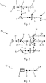
Comme illustré à la
Le système d'émission 1 est configuré pour générer un premier faisceau de lumière polarisée 4 selon une première direction 7 à partir du faisceau de lumière initial 3. Le faisceau polarisé dans la première direction 7 est représentée par un cercle plein. A cette fin, le système d'émission 1 comprend un séparateur 6, de préférence linéaire, configuré pour diviser le faisceau de lumière initiale 3 et former le premier faisceau de lumière polarisée 4. Le séparateur 6, qui est par exemple un polariseur, est agencé de préférence dans l'axe optique de la source de lumière 2. Ici, le séparateur 6 réfléchit la partie du faisceau de lumière initial 3 orientée dans la première direction, cette partie formant le premier faisceau de lumière polarisée 4, qui est dirigé ici sensiblement perpendiculairement à l'axe optique. Le système d'émission 1 comprend avantageusement un optique de collimation, non représenté sur les figures, disposé entre la source de lumière 2 et le séparateur 6. Un tel séparateur 6 comprend par exemple un polariseur à grille, ou un polariseur du type Glan-Thomson ou Wollaston, ou encore un prisme du type Nicol.The transmission system 1 is configured to generate a first
Dans d'autres modes de réalisation, on peut utiliser encore d'autres types de polariseur permettant d'obtenir une orientation des faisceaux polarisés autre que perpendiculaire et/ou parallèle à l'axe optiqueIn other embodiments, it is possible to use still other types of polarizer making it possible to obtain an orientation of the polarized beams other than perpendicular and / or parallel to the optical axis.
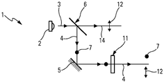
Le système de réception 10, représenté sur la
Selon l'invention, le système d'émission 1 comporte également un modulateur 11 de la direction de polarisation du premier faisceau de lumière polarisée 4, comme le montre la
Le modulateur 11 comporte ici un écran capable de moduler la polarisation du premier faisceau de lumière polarisée 4 entre ladite première direction 4 de polarisation et la deuxième direction 12 de polarisation. L'écran est par exemple un écran à cristaux liquides commutable entre une première configuration dans laquelle le premier faisceau de lumière polarisée 4 est transmis dans la première direction de polarisation 7, et une deuxième configuration dans laquelle le premier faisceau de lumière polarisée 4 est transmis dans la deuxième direction de polarisation 12. Dans la couche à cristaux-liquides de l'écran, la direction de la lumière polarisée peut-être modifiée par les cristaux liquides. En effet, lorsque les cristaux liquides sont disposés en couches chirales, ils transmettent le premier faisceau polarisé 4 en modifiant sa polarisation dans la deuxième direction 12. En revanche, lorsque les cristaux liquides sont orientés de façon isotrope dans la même direction, celle du champ électrique qui leurs est appliqué, ils transmettent le faisceau avec la même direction de polarisation, ici la première direction 7. Ainsi, l'orientation des cristaux-liquides détermine la direction de polarisation de la lumière.The
Le modulateur est, par exemple, pourvu d' un dispositif de commande, non représenté sur les figures, agencé pour commander la commutation de l'écran d'une configuration à l'autre, et induire ainsi la modulation du premier faisceau lumineux 4. Le dispositif de commande est de plus configuré pour engendrer le codage desdites informations grâce à la modulation par l'écran. De plus, un miroir 5 est agencé ici pour réfléchir le premier faisceau de lumière polarisé 4 vers le modulateur 11 en sortie du séparateur 6.The modulator is, for example, provided with a control device, not shown in the figures, arranged to control the switching of the screen from one configuration to another, and thus to induce the modulation of the
Le système d'émission 1 est avantageusement configuré pour que le faisceau d'éclairage soit en partie formé par le premier faisceau de lumière polarisée 4, et ceci quelle que soit sa direction de polarisation. Le premier faisceau polarisé 4 est émis avec une intensité sensiblement constante, même lorsque sa polarisation est modulée. Ainsi, l'intensité émise du faisceau d'éclairage équivaut sensiblement à la somme des intensités du premier faisceau polarisé et du deuxième faisceau polarisé. Dans ce cas, le miroir 5 a en outre pour fonction de réaligner les premier 4 et deuxième 14 faisceaux afin qu'ils constituent ensemble au moins en partie le faisceau d'éclairage généré par le système d'émission 1.The transmission system 1 is advantageously configured so that the illumination beam is partly formed by the first
Dans un mode de réalisation alternatif, le système d'émission 1 est configuré pour générer un faisceau d'éclairage à partir du faisceau de lumière initial 3. Pour cela, le séparateur 6 est apte à générer un deuxième faisceau de lumière 14 différent du premier. Ici, le deuxième faisceau de lumière 14 est polarisé dans la deuxième direction 12 de polarisation. Ici, le deuxième faisceau de lumière 14 est transmis par le séparateur 6 selon le même axe optique que le faisceau initial 3. Le deuxième faisceau polarisé 14 forme de préférence le faisceau d'éclairage généré par le système d'émission 1, au moins en partie.In an alternative embodiment, the transmission system 1 is configured to generate a lighting beam from the
Le système de de réception 10 détecte le premier faisceau lumineux 4 polarisé dans la première direction 7, et ne détecte pas le premier faisceau lumineux 4, lorsque ce dernier est polarisé dans la deuxième direction 12, ni le deuxième faisceau 14 également polarisé dans la deuxième direction 12. On obtient ainsi un faisceau d'éclairage d'intensité constante, dans lequel le premier faisceau lumineux a une direction de polarisation commutable entre les deux directions 7, 12 afin de transmettre des informations. Grâce à l'invention, le faisceau d'éclairage permet d'émettre des informations sans perdre de flux lumineux.The
Dans un autre mode de réalisation, le système de réception détectent le deuxième faisceau polarisé 14 dans la deuxième direction 12 et le premier faisceau lumineux 4 polarisé dans la deuxième direction 12, et ne détectent pas le premier faisceau lumineux 4, lorsque ce dernier est polarisé dans la première direction 7. On obtient ainsi un faisceau d'éclairage d'intensité constante, dans lequel le premier faisceau lumineux a une direction de polarisation commutable entre les deux directions 7, 12 afin de transmettre des informations. Grâce à l'invention, le faisceau d'éclairage permet d'émettre des informations sans perdre de flux lumineux.In another embodiment, the reception system detects the second
Sur la
Pour y parvenir, le système d'émission 21 comprend en plus d'un premier séparateur 26, un deuxième séparateur 36 agencé à l'intersection du premier faisceau de lumière polarisée 24 en sortie modulateur 31, et du deuxième faisceau de lumière polarisée 34. Le deuxième séparateur 36 a pour fonction de dévier le premier faisceau polarisé 24, lorsqu'il est dans la première direction de polarisation, dans la même direction que le deuxième faisceau de lumière polarisé. En revanche, le séparateur 36 laisse passer la lumière qui est polarisée dans la deuxième direction. Ainsi, lorsque le premier faisceau 24 est polarisé selon la deuxième direction 32, il traverse le séparateur sans être dévié. De même, le deuxième faisceau lumineux 34 qui arrive transversalement, traverse le séparateur 36. Le premier faisceau lumineux 24 est dévié selon le même axe optique que celui du deuxième faisceau lumineux polarisé 34, uniquement lorsqu'il est polarisé dans la première direction 27 de polarisation.To achieve this, the
Le système d'émission 21 est ici doté d'un premier 35 et d'un deuxième 37 miroir supplémentaire. Le premier miroir 35 est agencé pour réfléchir le premier faisceau de lumière polarisé 24 vers le deuxième séparateur 36, après le modulateur 31. Le deuxième miroir 37 réfléchit le premier faisceau lumineux polarisé dans la deuxième direction 32, après la transmission à travers le deuxième séparateur, de manière à le dirigé dans une direction préférentielle.The
Dans ce mode de réalisation, le faisceau d'éclairage du dispositif est formé par la recombinaison du premier faisceau de lumière 24 polarisée selon la première direction 27 et le deuxième faisceau 34 de lumière polarisée dans la deuxième direction 32. Le premier faisceau de lumière polarisée 24 dans la deuxième direction 32 est décalé. Il peut aussi servir pour former le faisceau d'éclairage afin que le faisceau d'éclairage garde une intensité constante pendant la modulation.In this embodiment, the illumination beam of the device is formed by the recombination of the
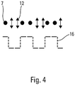
La
Ainsi, en activant le modulateur, on peut coder des informations à transmettre du système d'émission au système de réception par modulation.Thus, by activating the modulator, it is possible to encode information to be transmitted from the transmission system to the modulation reception system.
Dans une première variante de réalisation, non représentée sur les figures, la source de lumière est une source de lumière polarisée, telle une source laser. La source laser permet d'obtenir directement le premier faisceau polarisé. Le faisceau initial est néanmoins séparé en deux par un séparateur afin d'obtenir un premier et un deuxième faisceau polarisé.In a first variant embodiment, not shown in the figures, the light source is a source of polarized light, such as a laser source. The laser source makes it possible to obtain directly the first polarized beam. The initial beam is nevertheless separated in two by a separator in order to obtain a first and a second polarized beam.
Alternativement, le système d'émission comprend en plus un élément de conversion de longueur d'onde agencé pour transformer le faisceau de lumière initial polarisée en un faisceau de lumière non polarisée. Un tel convertisseur de lumière comprend un matériau luminescent conçu pour absorber au moins une partie d'une lumière d'excitation émise par une source lumineuse, et pour convertir au moins une partie de ladite lumière d'excitation absorbée en une lumière d'émission ayant une longueur d'onde différente de celle de la lumière d'excitation. Comme le matériau luminescent diffuse la lumière émise et transmise, la lumière du faisceau de lumière ainsi généré est non polarisée. La modulation et la séparation sont effectuées après la conversion de longueur d'onde du faisceau initial par le convertisseur. Dans ce cas, une partie seulement du faisceau initial converti est utilisé pour la communication. On peut en outre utiliser un filtre accordé sur la longueur d'onde du laser pour augmenter le rapport signal sur bruit. Il est à noter que le faisceau initial converti est soit la lumière transmise par le matériau luminescent, soit la lumière convertie par le matériau luminescent, soit la synthèse additive de la lumière transmise et la lumière convertie par le matériau luminescent.Alternatively, the transmission system further comprises a wavelength conversion element arranged to transform the initial polarized light beam into an unpolarized light beam. Such a light converter comprises a luminescent material adapted to absorb at least a portion of an excitation light emitted by a light source, and to convert at least a portion of said absorbed excitation light into a light source having a wavelength different from that of the excitation light. As the luminescent material diffuses the emitted and transmitted light, the light of the light beam thus generated is unpolarized. The modulation and separation are performed after the wavelength conversion of the initial beam by the converter. In this case, only part of the converted initial beam is used for communication. In addition, a filter tuned to the wavelength of the laser can be used to increase the signal-to-noise ratio. It should be noted that the converted initial beam is either the light transmitted by the luminescent material, the light converted by the luminescent material, or the additive synthesis of the transmitted light and the light converted by the luminescent material.
Dans une deuxième variante de réalisation, non représentée sur les figures, la source de lumière est une source infrarouge qui génère un faisceau de lumière initiale infrarouge. Le fonctionnement est le même que dans les réalisations précédentes.In a second variant embodiment, not shown in the figures, the light source is an infrared source that generates a beam of light initial infrared. The operation is the same as in previous achievements.
Dans un autre mode de réalisation, non représenté sur les figures, la modulation de la polarisation du premier faisceau lumineux est associée à une modulation pulsée de l'allumage de la source de lumière. Ainsi, on peut utiliser deux canaux de communication et augmenter la capacité et la vitesse de transfert d'informations entre le système d'émission et le système de réception. La fréquence de modulation pulsée est de préférence effectuée à haute fréquence.In another embodiment, not shown in the figures, the modulation of the polarization of the first light beam is associated with a pulsed modulation of the ignition of the light source. Thus, two communication channels can be used and the capacity and speed of information transfer between the transmission system and the reception system can be increased. The pulsed modulation frequency is preferably performed at a high frequency.
Claims (15)
Applications Claiming Priority (1)
| Application Number | Priority Date | Filing Date | Title |
|---|---|---|---|
| FR1751277A FR3065296B1 (en) | 2017-02-17 | 2017-02-17 | COMMUNICATION DEVICE, ESPECIALLY FOR MOTOR VEHICLES |
Publications (2)
| Publication Number | Publication Date |
|---|---|
| EP3364564A1 true EP3364564A1 (en) | 2018-08-22 |
| EP3364564B1 EP3364564B1 (en) | 2020-04-29 |
Family
ID=58739113
Family Applications (1)
| Application Number | Title | Priority Date | Filing Date |
|---|---|---|---|
| EP18156171.3A Active EP3364564B1 (en) | 2017-02-17 | 2018-02-09 | Optical communication system for vehicles |
Country Status (5)
| Country | Link |
|---|---|
| US (1) | US11030897B2 (en) |
| EP (1) | EP3364564B1 (en) |
| JP (1) | JP2018157545A (en) |
| CN (1) | CN108454504B (en) |
| FR (1) | FR3065296B1 (en) |
Families Citing this family (4)
| Publication number | Priority date | Publication date | Assignee | Title |
|---|---|---|---|---|
| JP6728251B2 (en) * | 2018-01-26 | 2020-07-22 | キヤノン株式会社 | Lighting device and image projection device |
| US10469177B1 (en) * | 2018-04-02 | 2019-11-05 | X Development Llc | Method for tracking a signal source based on polarization modulation |
| KR20210047871A (en) | 2018-08-24 | 2021-04-30 | 네셔날 인더스트리 인포메이션 리서치 인스티튜트 씨오., 엘티디. | Gripper, guide device, clamping device |
| DE102021001938A1 (en) * | 2020-05-04 | 2021-11-04 | Sew-Eurodrive Gmbh & Co Kg | Method and system for data transmission by means of light |
Citations (3)
| Publication number | Priority date | Publication date | Assignee | Title |
|---|---|---|---|---|
| US6310707B1 (en) * | 1996-10-25 | 2001-10-30 | Seiko Epson Corporation | Optical wireless data communication system, and transmitter and receiver used therefor |
| EP1515292A1 (en) * | 2002-06-05 | 2005-03-16 | Sony Corporation | Communication system for vehicle, vehicle, and communication device for vehicle |
| US20060269293A1 (en) * | 2005-05-30 | 2006-11-30 | Kyocera Corporation | Wireless communication system, wireless transmitting apparatus, and wireless receiving apparatus |
Family Cites Families (11)
| Publication number | Priority date | Publication date | Assignee | Title |
|---|---|---|---|---|
| US5052799A (en) * | 1989-07-17 | 1991-10-01 | Thurman Sasser | Object orienting systems and systems and processes relating thereto |
| DE10027018B4 (en) * | 2000-05-31 | 2010-09-09 | Robert Bosch Gmbh | Vehicle headlight according to the projection principle and lighting device of a vehicle with at least one such headlight |
| JP4265662B2 (en) * | 2007-02-06 | 2009-05-20 | 株式会社デンソー | Vehicle communication device |
| CN101394269B (en) * | 2008-08-07 | 2011-05-11 | 清华大学 | Remote communication method directly safely communicating with quantum by using quantum state injection reinforcement |
| WO2010062481A1 (en) * | 2008-11-02 | 2010-06-03 | David Chaum | Near to eye display system and appliance |
| US20100245127A1 (en) * | 2009-03-30 | 2010-09-30 | Vuong Binh Hong | Garage parking assistant |
| DE102012205891A1 (en) * | 2012-04-11 | 2013-10-17 | Continental Automotive Gmbh | Communication device for a vehicle |
| DE102014214601A1 (en) * | 2014-07-24 | 2016-01-28 | Osram Gmbh | Lighting device with at least one light sensor |
| US20160066559A1 (en) * | 2014-09-10 | 2016-03-10 | David F. Russell | Apparatus and method for using uv light to reduce collisions with animals |
| CN204886978U (en) * | 2015-06-10 | 2015-12-16 | 北京交通大学 | Equal 36 adjustable frequency -doubled signal generating device of no filtering compensation suppressed carrier system |
| KR101795218B1 (en) * | 2016-03-07 | 2017-11-08 | 현대자동차주식회사 | Lighting apparatus for vehicle |
-
2017
- 2017-02-17 FR FR1751277A patent/FR3065296B1/en active Active
-
2018
- 2018-02-09 EP EP18156171.3A patent/EP3364564B1/en active Active
- 2018-02-12 CN CN201810147868.2A patent/CN108454504B/en active Active
- 2018-02-16 JP JP2018026384A patent/JP2018157545A/en active Pending
- 2018-02-20 US US15/899,392 patent/US11030897B2/en active Active
Patent Citations (4)
| Publication number | Priority date | Publication date | Assignee | Title |
|---|---|---|---|---|
| US6310707B1 (en) * | 1996-10-25 | 2001-10-30 | Seiko Epson Corporation | Optical wireless data communication system, and transmitter and receiver used therefor |
| EP1515292A1 (en) * | 2002-06-05 | 2005-03-16 | Sony Corporation | Communication system for vehicle, vehicle, and communication device for vehicle |
| US20060119489A1 (en) | 2002-06-05 | 2006-06-08 | Sony Corporation | Communication system for vehicle, vehicle, and communication device for vehicle |
| US20060269293A1 (en) * | 2005-05-30 | 2006-11-30 | Kyocera Corporation | Wireless communication system, wireless transmitting apparatus, and wireless receiving apparatus |
Also Published As
| Publication number | Publication date |
|---|---|
| EP3364564B1 (en) | 2020-04-29 |
| CN108454504B (en) | 2021-10-08 |
| US20180240338A1 (en) | 2018-08-23 |
| JP2018157545A (en) | 2018-10-04 |
| US11030897B2 (en) | 2021-06-08 |
| FR3065296B1 (en) | 2020-08-28 |
| CN108454504A (en) | 2018-08-28 |
| FR3065296A1 (en) | 2018-10-19 |
Similar Documents
| Publication | Publication Date | Title |
|---|---|---|
| EP3364564B1 (en) | Optical communication system for vehicles | |
| EP2821692B1 (en) | Secure optical module for a motor vehicle including a laser source | |
| FR2860465A1 (en) | DEVICE FOR IMPROVING VISION CONDITIONS IN A VEHICLE | |
| EP3049855A1 (en) | Data-display glasses comprising an anti-glare screen | |
| FR3046978A1 (en) | COMMUNICATION DEVICE BETWEEN A VEHICLE AND AN AUTOMATIC PARKING SYSTEM | |
| FR3036771A1 (en) | LUMINOUS LIGHTING AND / OR SIGNALING DEVICE FOR VEHICLE | |
| WO2015044349A2 (en) | Driving assistance method and device | |
| WO2017025440A1 (en) | Lighting and/or signalling device for a motor vehicle | |
| EP3507542B1 (en) | Lighting and/or signalling device, in particular for an automotive vehicle | |
| EP2738448A2 (en) | Illuminating and/or signalling device, more particularly for automobile vehicle | |
| EP2803903A1 (en) | Lighting and/or signalling device, in particular for a motor vehicle | |
| EP3049281B1 (en) | Driving assistance method and device | |
| FR2926511A1 (en) | AUTOMATIC BRAKING SYSTEM OF A VEHICLE | |
| EP2394853A1 (en) | Method for communication between a transmitting vehicle and a target | |
| EP3432031A1 (en) | Detection of objects for motor vehicle | |
| FR2988052A1 (en) | Method for adapting e.g. brightness of illuminating or signaling light source of car, involves determining brightness value of light source, and adjusting brightness value in order to reach value of determined characteristic brightness | |
| FR2953623A1 (en) | Vehicle e.g. car, has transmitter/receiver comprising control device that modulates intensity of light signal emitted by LED light based on message and determines another message based on signal measured by optical detector | |
| EP0407300A1 (en) | On board electronic anti-collision device for a vehicle | |
| EP3306834B1 (en) | A railway vehicle having a data transmitting device | |
| FR3010570A1 (en) | COMMUNICATION DEVICE FOR EQUIPPING A MOTOR VEHICLE HABITACLE | |
| FR3049526A1 (en) | METHOD FOR CONTROLLING AUTOMATIC DISPLAY OF A PICTOGRAM REPRESENTING A SITUATION BASED ON A SIGNAL RECEIVED FROM A REMOTE TERMINAL | |
| WO2023213666A1 (en) | Detection and/or communication system for a motor vehicle comprising a module for receiving a light beam | |
| WO2024068697A1 (en) | Detecting and/or communicating system for a motor vehicle comprising a module for emitting and a module for receiving a light beam | |
| FR2860456A1 (en) | DEVICE FOR IMPROVING VISION CONDITIONS IN A VEHICLE | |
| FR2687820A1 (en) | Device for transmitting and retransmitting the braking information for motor vehicles |
Legal Events
| Date | Code | Title | Description |
|---|---|---|---|
| PUAI | Public reference made under article 153(3) epc to a published international application that has entered the european phase |
Free format text: ORIGINAL CODE: 0009012 |
|
| STAA | Information on the status of an ep patent application or granted ep patent |
Free format text: STATUS: THE APPLICATION HAS BEEN PUBLISHED |
|
| AK | Designated contracting states |
Kind code of ref document: A1 Designated state(s): AL AT BE BG CH CY CZ DE DK EE ES FI FR GB GR HR HU IE IS IT LI LT LU LV MC MK MT NL NO PL PT RO RS SE SI SK SM TR |
|
| AX | Request for extension of the european patent |
Extension state: BA ME |
|
| STAA | Information on the status of an ep patent application or granted ep patent |
Free format text: STATUS: REQUEST FOR EXAMINATION WAS MADE |
|
| 17P | Request for examination filed |
Effective date: 20190221 |
|
| RBV | Designated contracting states (corrected) |
Designated state(s): AL AT BE BG CH CY CZ DE DK EE ES FI FR GB GR HR HU IE IS IT LI LT LU LV MC MK MT NL NO PL PT RO RS SE SI SK SM TR |
|
| GRAP | Despatch of communication of intention to grant a patent |
Free format text: ORIGINAL CODE: EPIDOSNIGR1 |
|
| STAA | Information on the status of an ep patent application or granted ep patent |
Free format text: STATUS: GRANT OF PATENT IS INTENDED |
|
| RIC1 | Information provided on ipc code assigned before grant |
Ipc: H04B 10/114 20130101AFI20191030BHEP Ipc: H04B 10/116 20130101ALI20191030BHEP |
|
| INTG | Intention to grant announced |
Effective date: 20191127 |
|
| GRAS | Grant fee paid |
Free format text: ORIGINAL CODE: EPIDOSNIGR3 |
|
| GRAA | (expected) grant |
Free format text: ORIGINAL CODE: 0009210 |
|
| STAA | Information on the status of an ep patent application or granted ep patent |
Free format text: STATUS: THE PATENT HAS BEEN GRANTED |
|
| AK | Designated contracting states |
Kind code of ref document: B1 Designated state(s): AL AT BE BG CH CY CZ DE DK EE ES FI FR GB GR HR HU IE IS IT LI LT LU LV MC MK MT NL NO PL PT RO RS SE SI SK SM TR |
|
| REG | Reference to a national code |
Ref country code: GB Ref legal event code: FG4D Free format text: NOT ENGLISH |
|
| REG | Reference to a national code |
Ref country code: CH Ref legal event code: EP |
|
| REG | Reference to a national code |
Ref country code: AT Ref legal event code: REF Ref document number: 1264883 Country of ref document: AT Kind code of ref document: T Effective date: 20200515 |
|
| REG | Reference to a national code |
Ref country code: DE Ref legal event code: R096 Ref document number: 602018004045 Country of ref document: DE |
|
| REG | Reference to a national code |
Ref country code: IE Ref legal event code: FG4D Free format text: LANGUAGE OF EP DOCUMENT: FRENCH |
|
| REG | Reference to a national code |
Ref country code: NL Ref legal event code: MP Effective date: 20200429 |
|
| REG | Reference to a national code |
Ref country code: LT Ref legal event code: MG4D |
|
| PG25 | Lapsed in a contracting state [announced via postgrant information from national office to epo] |
Ref country code: LT Free format text: LAPSE BECAUSE OF FAILURE TO SUBMIT A TRANSLATION OF THE DESCRIPTION OR TO PAY THE FEE WITHIN THE PRESCRIBED TIME-LIMIT Effective date: 20200429 Ref country code: NO Free format text: LAPSE BECAUSE OF FAILURE TO SUBMIT A TRANSLATION OF THE DESCRIPTION OR TO PAY THE FEE WITHIN THE PRESCRIBED TIME-LIMIT Effective date: 20200729 Ref country code: FI Free format text: LAPSE BECAUSE OF FAILURE TO SUBMIT A TRANSLATION OF THE DESCRIPTION OR TO PAY THE FEE WITHIN THE PRESCRIBED TIME-LIMIT Effective date: 20200429 Ref country code: IS Free format text: LAPSE BECAUSE OF FAILURE TO SUBMIT A TRANSLATION OF THE DESCRIPTION OR TO PAY THE FEE WITHIN THE PRESCRIBED TIME-LIMIT Effective date: 20200829 Ref country code: PT Free format text: LAPSE BECAUSE OF FAILURE TO SUBMIT A TRANSLATION OF THE DESCRIPTION OR TO PAY THE FEE WITHIN THE PRESCRIBED TIME-LIMIT Effective date: 20200831 Ref country code: GR Free format text: LAPSE BECAUSE OF FAILURE TO SUBMIT A TRANSLATION OF THE DESCRIPTION OR TO PAY THE FEE WITHIN THE PRESCRIBED TIME-LIMIT Effective date: 20200730 Ref country code: SE Free format text: LAPSE BECAUSE OF FAILURE TO SUBMIT A TRANSLATION OF THE DESCRIPTION OR TO PAY THE FEE WITHIN THE PRESCRIBED TIME-LIMIT Effective date: 20200429 |
|
| REG | Reference to a national code |
Ref country code: AT Ref legal event code: MK05 Ref document number: 1264883 Country of ref document: AT Kind code of ref document: T Effective date: 20200429 |
|
| PG25 | Lapsed in a contracting state [announced via postgrant information from national office to epo] |
Ref country code: HR Free format text: LAPSE BECAUSE OF FAILURE TO SUBMIT A TRANSLATION OF THE DESCRIPTION OR TO PAY THE FEE WITHIN THE PRESCRIBED TIME-LIMIT Effective date: 20200429 Ref country code: BG Free format text: LAPSE BECAUSE OF FAILURE TO SUBMIT A TRANSLATION OF THE DESCRIPTION OR TO PAY THE FEE WITHIN THE PRESCRIBED TIME-LIMIT Effective date: 20200729 Ref country code: LV Free format text: LAPSE BECAUSE OF FAILURE TO SUBMIT A TRANSLATION OF THE DESCRIPTION OR TO PAY THE FEE WITHIN THE PRESCRIBED TIME-LIMIT Effective date: 20200429 Ref country code: RS Free format text: LAPSE BECAUSE OF FAILURE TO SUBMIT A TRANSLATION OF THE DESCRIPTION OR TO PAY THE FEE WITHIN THE PRESCRIBED TIME-LIMIT Effective date: 20200429 |
|
| PG25 | Lapsed in a contracting state [announced via postgrant information from national office to epo] |
Ref country code: AL Free format text: LAPSE BECAUSE OF FAILURE TO SUBMIT A TRANSLATION OF THE DESCRIPTION OR TO PAY THE FEE WITHIN THE PRESCRIBED TIME-LIMIT Effective date: 20200429 Ref country code: NL Free format text: LAPSE BECAUSE OF FAILURE TO SUBMIT A TRANSLATION OF THE DESCRIPTION OR TO PAY THE FEE WITHIN THE PRESCRIBED TIME-LIMIT Effective date: 20200429 |
|
| PG25 | Lapsed in a contracting state [announced via postgrant information from national office to epo] |
Ref country code: ES Free format text: LAPSE BECAUSE OF FAILURE TO SUBMIT A TRANSLATION OF THE DESCRIPTION OR TO PAY THE FEE WITHIN THE PRESCRIBED TIME-LIMIT Effective date: 20200429 Ref country code: CZ Free format text: LAPSE BECAUSE OF FAILURE TO SUBMIT A TRANSLATION OF THE DESCRIPTION OR TO PAY THE FEE WITHIN THE PRESCRIBED TIME-LIMIT Effective date: 20200429 Ref country code: AT Free format text: LAPSE BECAUSE OF FAILURE TO SUBMIT A TRANSLATION OF THE DESCRIPTION OR TO PAY THE FEE WITHIN THE PRESCRIBED TIME-LIMIT Effective date: 20200429 Ref country code: DK Free format text: LAPSE BECAUSE OF FAILURE TO SUBMIT A TRANSLATION OF THE DESCRIPTION OR TO PAY THE FEE WITHIN THE PRESCRIBED TIME-LIMIT Effective date: 20200429 Ref country code: SM Free format text: LAPSE BECAUSE OF FAILURE TO SUBMIT A TRANSLATION OF THE DESCRIPTION OR TO PAY THE FEE WITHIN THE PRESCRIBED TIME-LIMIT Effective date: 20200429 Ref country code: EE Free format text: LAPSE BECAUSE OF FAILURE TO SUBMIT A TRANSLATION OF THE DESCRIPTION OR TO PAY THE FEE WITHIN THE PRESCRIBED TIME-LIMIT Effective date: 20200429 Ref country code: RO Free format text: LAPSE BECAUSE OF FAILURE TO SUBMIT A TRANSLATION OF THE DESCRIPTION OR TO PAY THE FEE WITHIN THE PRESCRIBED TIME-LIMIT Effective date: 20200429 Ref country code: IT Free format text: LAPSE BECAUSE OF FAILURE TO SUBMIT A TRANSLATION OF THE DESCRIPTION OR TO PAY THE FEE WITHIN THE PRESCRIBED TIME-LIMIT Effective date: 20200429 |
|
| REG | Reference to a national code |
Ref country code: DE Ref legal event code: R097 Ref document number: 602018004045 Country of ref document: DE |
|
| PG25 | Lapsed in a contracting state [announced via postgrant information from national office to epo] |
Ref country code: PL Free format text: LAPSE BECAUSE OF FAILURE TO SUBMIT A TRANSLATION OF THE DESCRIPTION OR TO PAY THE FEE WITHIN THE PRESCRIBED TIME-LIMIT Effective date: 20200429 Ref country code: SK Free format text: LAPSE BECAUSE OF FAILURE TO SUBMIT A TRANSLATION OF THE DESCRIPTION OR TO PAY THE FEE WITHIN THE PRESCRIBED TIME-LIMIT Effective date: 20200429 |
|
| PLBE | No opposition filed within time limit |
Free format text: ORIGINAL CODE: 0009261 |
|
| STAA | Information on the status of an ep patent application or granted ep patent |
Free format text: STATUS: NO OPPOSITION FILED WITHIN TIME LIMIT |
|
| 26N | No opposition filed |
Effective date: 20210201 |
|
| PG25 | Lapsed in a contracting state [announced via postgrant information from national office to epo] |
Ref country code: SI Free format text: LAPSE BECAUSE OF FAILURE TO SUBMIT A TRANSLATION OF THE DESCRIPTION OR TO PAY THE FEE WITHIN THE PRESCRIBED TIME-LIMIT Effective date: 20200429 |
|
| PG25 | Lapsed in a contracting state [announced via postgrant information from national office to epo] |
Ref country code: MC Free format text: LAPSE BECAUSE OF FAILURE TO SUBMIT A TRANSLATION OF THE DESCRIPTION OR TO PAY THE FEE WITHIN THE PRESCRIBED TIME-LIMIT Effective date: 20200429 |
|
| REG | Reference to a national code |
Ref country code: BE Ref legal event code: MM Effective date: 20210228 |
|
| PG25 | Lapsed in a contracting state [announced via postgrant information from national office to epo] |
Ref country code: LI Free format text: LAPSE BECAUSE OF NON-PAYMENT OF DUE FEES Effective date: 20210228 Ref country code: LU Free format text: LAPSE BECAUSE OF NON-PAYMENT OF DUE FEES Effective date: 20210209 Ref country code: CH Free format text: LAPSE BECAUSE OF NON-PAYMENT OF DUE FEES Effective date: 20210228 |
|
| PG25 | Lapsed in a contracting state [announced via postgrant information from national office to epo] |
Ref country code: IE Free format text: LAPSE BECAUSE OF NON-PAYMENT OF DUE FEES Effective date: 20210209 |
|
| PG25 | Lapsed in a contracting state [announced via postgrant information from national office to epo] |
Ref country code: BE Free format text: LAPSE BECAUSE OF NON-PAYMENT OF DUE FEES Effective date: 20210228 |
|
| GBPC | Gb: european patent ceased through non-payment of renewal fee |
Effective date: 20220209 |
|
| PG25 | Lapsed in a contracting state [announced via postgrant information from national office to epo] |
Ref country code: GB Free format text: LAPSE BECAUSE OF NON-PAYMENT OF DUE FEES Effective date: 20220209 |
|
| PGFP | Annual fee paid to national office [announced via postgrant information from national office to epo] |
Ref country code: FR Payment date: 20230227 Year of fee payment: 6 |
|
| PGFP | Annual fee paid to national office [announced via postgrant information from national office to epo] |
Ref country code: DE Payment date: 20230207 Year of fee payment: 6 |
|
| PG25 | Lapsed in a contracting state [announced via postgrant information from national office to epo] |
Ref country code: CY Free format text: LAPSE BECAUSE OF FAILURE TO SUBMIT A TRANSLATION OF THE DESCRIPTION OR TO PAY THE FEE WITHIN THE PRESCRIBED TIME-LIMIT Effective date: 20200429 |
|
| P01 | Opt-out of the competence of the unified patent court (upc) registered |
Effective date: 20230528 |
|
| PG25 | Lapsed in a contracting state [announced via postgrant information from national office to epo] |
Ref country code: HU Free format text: LAPSE BECAUSE OF FAILURE TO SUBMIT A TRANSLATION OF THE DESCRIPTION OR TO PAY THE FEE WITHIN THE PRESCRIBED TIME-LIMIT; INVALID AB INITIO Effective date: 20180209 |