EP3364480B1 - Battery pack - Google Patents
Battery pack Download PDFInfo
- Publication number
- EP3364480B1 EP3364480B1 EP17001453.4A EP17001453A EP3364480B1 EP 3364480 B1 EP3364480 B1 EP 3364480B1 EP 17001453 A EP17001453 A EP 17001453A EP 3364480 B1 EP3364480 B1 EP 3364480B1
- Authority
- EP
- European Patent Office
- Prior art keywords
- cartridges
- duct
- cartridge
- ducts
- battery
- Prior art date
- Legal status (The legal status is an assumption and is not a legal conclusion. Google has not performed a legal analysis and makes no representation as to the accuracy of the status listed.)
- Active
Links
- 238000007789 sealing Methods 0.000 claims description 16
- 239000007769 metal material Substances 0.000 claims description 3
- 238000001816 cooling Methods 0.000 description 15
- 230000017525 heat dissipation Effects 0.000 description 5
- 239000012528 membrane Substances 0.000 description 4
- 239000012530 fluid Substances 0.000 description 3
- 229920003002 synthetic resin Polymers 0.000 description 3
- XAGFODPZIPBFFR-UHFFFAOYSA-N aluminium Chemical compound [Al] XAGFODPZIPBFFR-UHFFFAOYSA-N 0.000 description 2
- 229910052782 aluminium Inorganic materials 0.000 description 2
- 230000005540 biological transmission Effects 0.000 description 2
- 239000000463 material Substances 0.000 description 2
- 239000000057 synthetic resin Substances 0.000 description 2
- 238000004378 air conditioning Methods 0.000 description 1
- 239000004411 aluminium Substances 0.000 description 1
- 238000005452 bending Methods 0.000 description 1
- 230000037237 body shape Effects 0.000 description 1
- 230000001419 dependent effect Effects 0.000 description 1
- 238000007599 discharging Methods 0.000 description 1
- 230000000694 effects Effects 0.000 description 1
- 238000010438 heat treatment Methods 0.000 description 1
- 229910052755 nonmetal Inorganic materials 0.000 description 1
- 239000002952 polymeric resin Substances 0.000 description 1
- 230000001681 protective effect Effects 0.000 description 1
- 239000000126 substance Substances 0.000 description 1
- 238000009423 ventilation Methods 0.000 description 1
Images


Classifications
-
- H—ELECTRICITY
- H01—ELECTRIC ELEMENTS
- H01M—PROCESSES OR MEANS, e.g. BATTERIES, FOR THE DIRECT CONVERSION OF CHEMICAL ENERGY INTO ELECTRICAL ENERGY
- H01M10/00—Secondary cells; Manufacture thereof
- H01M10/60—Heating or cooling; Temperature control
- H01M10/65—Means for temperature control structurally associated with the cells
- H01M10/655—Solid structures for heat exchange or heat conduction
- H01M10/6551—Surfaces specially adapted for heat dissipation or radiation, e.g. fins or coatings
-
- H—ELECTRICITY
- H01—ELECTRIC ELEMENTS
- H01M—PROCESSES OR MEANS, e.g. BATTERIES, FOR THE DIRECT CONVERSION OF CHEMICAL ENERGY INTO ELECTRICAL ENERGY
- H01M10/00—Secondary cells; Manufacture thereof
- H01M10/60—Heating or cooling; Temperature control
- H01M10/65—Means for temperature control structurally associated with the cells
- H01M10/656—Means for temperature control structurally associated with the cells characterised by the type of heat-exchange fluid
- H01M10/6561—Gases
- H01M10/6566—Means within the gas flow to guide the flow around one or more cells, e.g. manifolds, baffles or other barriers
-
- H—ELECTRICITY
- H01—ELECTRIC ELEMENTS
- H01M—PROCESSES OR MEANS, e.g. BATTERIES, FOR THE DIRECT CONVERSION OF CHEMICAL ENERGY INTO ELECTRICAL ENERGY
- H01M10/00—Secondary cells; Manufacture thereof
- H01M10/60—Heating or cooling; Temperature control
- H01M10/61—Types of temperature control
- H01M10/613—Cooling or keeping cold
-
- H—ELECTRICITY
- H01—ELECTRIC ELEMENTS
- H01M—PROCESSES OR MEANS, e.g. BATTERIES, FOR THE DIRECT CONVERSION OF CHEMICAL ENERGY INTO ELECTRICAL ENERGY
- H01M10/00—Secondary cells; Manufacture thereof
- H01M10/60—Heating or cooling; Temperature control
- H01M10/62—Heating or cooling; Temperature control specially adapted for specific applications
- H01M10/625—Vehicles
-
- H—ELECTRICITY
- H01—ELECTRIC ELEMENTS
- H01M—PROCESSES OR MEANS, e.g. BATTERIES, FOR THE DIRECT CONVERSION OF CHEMICAL ENERGY INTO ELECTRICAL ENERGY
- H01M10/00—Secondary cells; Manufacture thereof
- H01M10/60—Heating or cooling; Temperature control
- H01M10/64—Heating or cooling; Temperature control characterised by the shape of the cells
- H01M10/647—Prismatic or flat cells, e.g. pouch cells
-
- H—ELECTRICITY
- H01—ELECTRIC ELEMENTS
- H01M—PROCESSES OR MEANS, e.g. BATTERIES, FOR THE DIRECT CONVERSION OF CHEMICAL ENERGY INTO ELECTRICAL ENERGY
- H01M10/00—Secondary cells; Manufacture thereof
- H01M10/60—Heating or cooling; Temperature control
- H01M10/65—Means for temperature control structurally associated with the cells
- H01M10/655—Solid structures for heat exchange or heat conduction
- H01M10/6556—Solid parts with flow channel passages or pipes for heat exchange
- H01M10/6557—Solid parts with flow channel passages or pipes for heat exchange arranged between the cells
-
- H—ELECTRICITY
- H01—ELECTRIC ELEMENTS
- H01M—PROCESSES OR MEANS, e.g. BATTERIES, FOR THE DIRECT CONVERSION OF CHEMICAL ENERGY INTO ELECTRICAL ENERGY
- H01M10/00—Secondary cells; Manufacture thereof
- H01M10/60—Heating or cooling; Temperature control
- H01M10/65—Means for temperature control structurally associated with the cells
- H01M10/656—Means for temperature control structurally associated with the cells characterised by the type of heat-exchange fluid
- H01M10/6561—Gases
- H01M10/6562—Gases with free flow by convection only
-
- H—ELECTRICITY
- H01—ELECTRIC ELEMENTS
- H01M—PROCESSES OR MEANS, e.g. BATTERIES, FOR THE DIRECT CONVERSION OF CHEMICAL ENERGY INTO ELECTRICAL ENERGY
- H01M10/00—Secondary cells; Manufacture thereof
- H01M10/60—Heating or cooling; Temperature control
- H01M10/65—Means for temperature control structurally associated with the cells
- H01M10/656—Means for temperature control structurally associated with the cells characterised by the type of heat-exchange fluid
- H01M10/6561—Gases
- H01M10/6563—Gases with forced flow, e.g. by blowers
- H01M10/6565—Gases with forced flow, e.g. by blowers with recirculation or U-turn in the flow path, i.e. back and forth
-
- H—ELECTRICITY
- H01—ELECTRIC ELEMENTS
- H01M—PROCESSES OR MEANS, e.g. BATTERIES, FOR THE DIRECT CONVERSION OF CHEMICAL ENERGY INTO ELECTRICAL ENERGY
- H01M10/00—Secondary cells; Manufacture thereof
- H01M10/60—Heating or cooling; Temperature control
- H01M10/66—Heat-exchange relationships between the cells and other systems, e.g. central heating systems or fuel cells
- H01M10/663—Heat-exchange relationships between the cells and other systems, e.g. central heating systems or fuel cells the system being an air-conditioner or an engine
-
- H—ELECTRICITY
- H01—ELECTRIC ELEMENTS
- H01M—PROCESSES OR MEANS, e.g. BATTERIES, FOR THE DIRECT CONVERSION OF CHEMICAL ENERGY INTO ELECTRICAL ENERGY
- H01M50/00—Constructional details or processes of manufacture of the non-active parts of electrochemical cells other than fuel cells, e.g. hybrid cells
- H01M50/20—Mountings; Secondary casings or frames; Racks, modules or packs; Suspension devices; Shock absorbers; Transport or carrying devices; Holders
- H01M50/271—Lids or covers for the racks or secondary casings
-
- H—ELECTRICITY
- H01—ELECTRIC ELEMENTS
- H01M—PROCESSES OR MEANS, e.g. BATTERIES, FOR THE DIRECT CONVERSION OF CHEMICAL ENERGY INTO ELECTRICAL ENERGY
- H01M50/00—Constructional details or processes of manufacture of the non-active parts of electrochemical cells other than fuel cells, e.g. hybrid cells
- H01M50/30—Arrangements for facilitating escape of gases
-
- H—ELECTRICITY
- H01—ELECTRIC ELEMENTS
- H01M—PROCESSES OR MEANS, e.g. BATTERIES, FOR THE DIRECT CONVERSION OF CHEMICAL ENERGY INTO ELECTRICAL ENERGY
- H01M2220/00—Batteries for particular applications
- H01M2220/20—Batteries in motive systems, e.g. vehicle, ship, plane
-
- H—ELECTRICITY
- H01—ELECTRIC ELEMENTS
- H01M—PROCESSES OR MEANS, e.g. BATTERIES, FOR THE DIRECT CONVERSION OF CHEMICAL ENERGY INTO ELECTRICAL ENERGY
- H01M50/00—Constructional details or processes of manufacture of the non-active parts of electrochemical cells other than fuel cells, e.g. hybrid cells
- H01M50/20—Mountings; Secondary casings or frames; Racks, modules or packs; Suspension devices; Shock absorbers; Transport or carrying devices; Holders
- H01M50/204—Racks, modules or packs for multiple batteries or multiple cells
- H01M50/207—Racks, modules or packs for multiple batteries or multiple cells characterised by their shape
- H01M50/211—Racks, modules or packs for multiple batteries or multiple cells characterised by their shape adapted for pouch cells
-
- Y—GENERAL TAGGING OF NEW TECHNOLOGICAL DEVELOPMENTS; GENERAL TAGGING OF CROSS-SECTIONAL TECHNOLOGIES SPANNING OVER SEVERAL SECTIONS OF THE IPC; TECHNICAL SUBJECTS COVERED BY FORMER USPC CROSS-REFERENCE ART COLLECTIONS [XRACs] AND DIGESTS
- Y02—TECHNOLOGIES OR APPLICATIONS FOR MITIGATION OR ADAPTATION AGAINST CLIMATE CHANGE
- Y02E—REDUCTION OF GREENHOUSE GAS [GHG] EMISSIONS, RELATED TO ENERGY GENERATION, TRANSMISSION OR DISTRIBUTION
- Y02E60/00—Enabling technologies; Technologies with a potential or indirect contribution to GHG emissions mitigation
- Y02E60/10—Energy storage using batteries
Definitions
- the present disclosure relates to a battery pack, and for example, to a battery pack including cartridges and battery cells.
- a battery pack is a device that can be assembled from a plurality of battery cells and that can supply power to other devices connected to the battery pack.
- a battery pack can be used in various industrial fields and various devices, such as mobile phones, home appliances, and vehicles.
- a battery pack may be mounted and used in electric vehicles that can be driven by the power from a driving motor, and the battery pack may include a plurality of battery cells and a plurality of cartridges that are configured to receive the battery cells.
- the battery pack may further include cooling plates for dissipating heat from the battery cells.
- the cooling plates may be in contact with the battery cells and can absorb heat from the battery cells.
- the battery pack may include the cooling plates made of a metallic material with a high thermal conductivity, such as aluminium. In these cases, the cooling plates may increase the weight of the battery pack.
- JP 2008 103248 A discloses a holding structure of a secondary battery capable of preventing a fluid from leaking from a fluid passage formed in a battery holder.
- EP 1 577 966 A2 discloses an accumulator device structured by a plurality of substantially identical and flat frames that accommodate accumulator cells.
- the frames can be stacked on one another to meet energy needs and an impact transmitted to the accumulator cells from the outside can be reduced.
- US 2012/0040222 A1 discloses a molded cooling fin and frame, including center cooling fins and outer cooling fins. The cooling fins and frames are included into a battery pack.
- EP 1 744 383 A1 discloses further prior art.
- a laminated battery is provided with a frame member surrounding and holding electric power generating elements.
- One of the objects of the present disclosure is to provide a battery pack that includes a relatively small number of parts, that is light, and that is able to cool a plurality of cartridges using air.
- Another object of the present disclosure is to provide a battery pack that can be made in a compact form factor.
- a battery pack includes a plurality of cartridges that are stackable in a vertical direction in which each cartridge of the plurality of cartridges extends in a longitudinal direction perpendicular to the vertical direction and a plurality of battery cells that are vertically arranged in contact with adjacent battery cells, wherein each battery cell is disposed in a cartridge of the plurality of cartridges.
- Each cartridge of the plurality of cartridges includes a battery cell contact body that is configured to contact a battery cell of the plurality of battery cells and support the battery cell, and at least one duct that is configured to transmit heat from the battery cell contact body to air by passing air through the at least one duct.
- Each duct of the plurality of cartridges is configured to communicate air with another duct of an adjacent cartridge.
- the battery cell contact body includes: a pair of contact portions protruding from the ducts and a pair of bridges connecting the contact portions, wherein the contact portions are in contact with a pair of battery cells, such that the battery cell contact body can receive heat from the battery cells.
- Implementations according to this aspect may include one or more of following features.
- the battery cell contact body and the duct may be integrally formed of a non-metallic material, and the duct may protrude upward relative to the battery cell contact body.
- the battery cell may have an upper surface that contacts a lower surface of an adjacent battery cell stacked above the battery cell.
- each duct of the plurality of cartridges may have a lower end and an upper end, the upper end being configured to seat a lower end of a duct from an adjacent cartridge, and each duct of the plurality of cartridges may be configured to vertically communicate air with ducts of adjacent cartridges that are stacked above and below.
- Each cartridge of the plurality of cartridges may include a pair of ducts that are spaced apart from each other in a width direction perpendicular to the longitudinal direction.
- the battery cell contact body may be configured to receive the battery cell in a battery cell space defined between the pair of ducts.
- the battery cell contact body includes: a pair of contact portions that protrude from a side surface of the pair of ducts, the pair of contact portions being spaced apart from each other in the width direction and extending in the longitudinal direction; and a pair of bridges that connect the pair of contact portions to each other, the pair of bridges being spaced apart from each other in the longitudinal direction and extending in the width direction.
- the battery pack may further include a base that defines a return channel configured to communicate with a pair of ducts of a lowermost cartridge.
- the return channel may include an inlet positioned under a first duct of the pair of ducts of the lowermost cartridge, an outlet positioned under a second duct of the pair of ducts of the lowermost cartridge, and a connection channel connecting the inlet to the outlet.
- the base may be configured to seat the pair of ducts of the lowermost cartridge.
- the base may define a recessed seat configured to receive a lowermost battery cell that is disposed in the lowermost cartridge.
- the battery pack may further include a top plate disposed vertically above an uppermost cartridge in which the top plate includes: an upper intake duct that is configured to communicate with a first duct of the pair of ducts of the uppermost cartridge, and an upper exhaust duct that is configured to communicate with a second duct of the pair of ducts of the uppermost cartridge.
- the top plate may further include a cover plate that extends from the upper intake duct to the upper exhaust duct and that covers at least a portion of an uppermost battery cell disposed in the uppermost cartridge.
- the battery pack may further include a pressing plate that is coupled to the top plate and configured to provide a pressure to the top plate and to the uppermost cartridge.
- the battery pack may further include a lower case, and an upper case that covers a top portion of the lower case in which the upper case defines an outer intake hole located vertically above the upper intake duct, and an outer exhaust hole located vertically above the upper exhaust duct.
- the battery pack may further include gas exhaust passages, each of the gas exhaust passages being defined between adjacent cartridges and configured to discharge gas from the battery cells in a direction perpendicular to an opening direction of the duct.
- each of the battery cells may include cell leads that protrude in the longitudinal direction
- each cartridge of the plurality of cartridges may include seating grooves that are configured to receive the cell leads
- the gas exhaust passages are defined between the seating grooves of the adjacent cartridges.
- the battery pack may further include an inner cover that faces predetermined sides of the plurality of cartridges.
- the inner cover may be spaced apart from the predetermined sides of the plurality of cartridges to thereby define a gap that allows flow of gas that has passed through the gas exhaust passages, and the inner cover may define an inner gas exhaust hole that is configured to discharge the gas from the gap.
- the battery pack may further include one or more sealing members that are configured to provide a seal between the ducts of the plurality of cartridges based on the plurality of cartridges being stacked.
- each cartridge of the plurality of cartridges may define sealing member grooves on top and bottom surfaces of the cartridge, the sealing member grooves being configured to receive the sealing members.
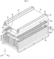
- FIG. 1 is a perspective view showing an example battery pack
- FIG. 2 is an exploded perspective view of the example battery pack shown in FIG. 1
- FIG. 3 is an exploded perspective view showing example battery cells and example cartridges.
- a battery pack may include an outer case 1 that forms the external appearance.
- An outer intake hole 2 through which air for cooling the inside the battery pack P flows into the outer case 1 may be formed at the outer case 1.
- An outer exhaust hole 3 through which the air that has cooled the inside of the battery pack P is discharged out of the battery pack P may be formed at the outer case 1.
- the battery pack P may be installed in a vehicle and may be mounted on the car body of a vehicle, for instance.
- the battery pack P may be connected with an HVAC (Heating Ventilation Air Conditioning), or the inside or the outside of a vehicle through a duct.
- HVAC Heating Ventilation Air Conditioning
- the battery pack P may be connected to an HVAC or an interior of a vehicle through an intake duct and an exhaust duct, in which the air from the intake duct can flow into the battery pack P through the outer intake hole 2 and remove the heat inside the battery pack P and the air in the battery pack P can be discharged out of the HVAC or the interior of the vehicle through the outer exhaust hole 3 and the exhaust duct.
- the intake duct may be connected to the battery pack P to guide air into the outer intake hole 2 and the exhaust duct may be connected to the battery pack P to guide the air discharged out of the outer exhaust hole 3.
- the intake duct may have an end connected to a portion around the outer intake hole 2 and the exhaust duct may have an end connected to a portion around the outer exhaust hole 3.
- An outer gas exhaust hole 4 through which gas G discharged from battery cells in the battery pack P is discharged out of the battery pack P may be formed at the outer case 1.
- the outer case 1 may have various shapes such as a polygonal shape, a hexahedron shape, and a round shape.
- the outer intake hole 2 and the outer exhaust hole 3 may be formed through a side of the outer case 1 and the outer gas exhaust hole 4 may be formed through any one of sides of the outer case 1 except for the side with the outer intake hole 2 and the outer exhaust hole 3.
- the outer intake hole 2 and the outer exhaust hole 3 may be open in parallel with each other.
- the outer gas exhaust hole 4 may be open in a different direction from the outer intake hole 2 and the outer exhaust hole 3.
- the outer intake hole 2 and the outer exhaust hole 3 may be open vertically in the outer case 1 (in the Z-axial direction), while the outer gas exhaust hole 4 may be open horizontally in the outer case 1 (in the Y-axial direction).
- the outer intake hole 2 and the outer exhaust hole 3 may be open horizontally in the outer case 1, while the outer gas exhaust hole 4 may be open vertically in the outer case 1.
- all of the outer intake hole 2, the outer exhaust hole 3, and the outer gas exhaust hole 4 may be horizontally open.
- the outer intake hole 2 and the outer exhaust hole 3 may be open in the left-right direction (in the X-axial direction), while the outer gas exhaust hole 4 may be open in the front-rear direction (in the Y-axial direction).
- the outer intake hole 2 and the outer exhaust hole 3 may be open in the front-rear direction (in the Y-axial direction), while the outer gas exhaust hole 4 may be open in the left-right direction (in the X-axial direction).
- the outer case 1 may be an assembly of a plurality of members and may include a lower case 5 and an upper case 6 covering the top of the lower case 5.
- a battery module 8 may be disposed in the outer case 1.
- the outer gas exhaust hole 4 may be formed at the lower case 5, and the outer intake hole 2 and the outer exhaust hole 3 may be formed at the upper case 6.
- the lower case 5 may be formed in a box shape with an open top.
- a space S1 that is open upward may be formed inside the lower case 5 and the battery module 8 may be partially or entirely inserted and kept in the space S1 of the lower case 5.
- the battery module 8 includes a plurality of battery cells 10 and a plurality of cartridges 20.
- the battery cells 10 are mounted on the cartridges 20.
- the battery cells 10 are vertically stacked on the cartridges 20.
- the battery cells 10 are vertically arranged to face adjacent battery cells.
- the cartridges 20 are stacked.
- the cartridges 20 are vertically arranged to face adjacent cartridges 20.
- the cartridges 20 are the same in shape and size and the common configurations of the cartridges 20 are given reference numeral '20' in the following description.
- the upper cartridge is given reference numeral '20A' and the lower cartridge which is adjacent to the upper cartridge is given reference numeral '20B' in the following description.
- the uppermost cartridge is given reference numeral '20C' and the lowermost cartridge is given reference numeral '20D' in the following description.
- the uppermost cartridge 20C may be an upper cartridge for the cartridge positioned right under it and is given reference numeral '20C' for the convenience of description in the following description.
- the lowermost cartridge 20D may be a lower cartridge for the cartridge positioned right over it and is given reference numeral '20D' for the convenience of description in the following description.
- an upper cartridge 20A is facing the top of a lower cartridge 20B which is adjacent to the upper cartridge 20A.
- the lower end of an upper cartridge 20A may be seated on the upper end of a lower cartridge 20B which is adjacent to the upper cartridge 20A.
- the cartridges 20 each include a battery cell contact body 22 that is in contact with a battery cell 10 and one or more ducts D1 and D2 for transmitting heat of the battery cell contact body 22 to air passing through it.
- the battery module 8 may include a base 40.
- the base 40 may form the external appearance of the bottom of the battery module 8.
- the lowermost cartridge 20D of the cartridges 20 may be disposed on the base 40 and the weight of the cartridges 20 may be applied to the base 40.
- the battery module 8 may further include a top plate 50.
- the top plate 50 may be disposed over the uppermost cartridge 20C.
- the top plate 50 can cover the top of the uppermost cartridge 20C and the top of the uppermost battery cell in the uppermost cartridge 20C.
- the battery pack P may include a membrane 9 disposed in the outer gas exhaust hole 4.
- the membrane 9 can prevent foreign substances from flowing inside through the outer gas exhaust hole 4.
- the membrane 9 may be breakable to relieve an internal air pressure when the internal pressure of the battery pack P exceeds a reference pressure. When the membrane 9 breaks, high-pressure fluid in the battery pack P may leak out of the battery pack P through the outer gas exhaust hole 4.
- the battery pack P may include inner covers 70 and 71 that cover predetermined sides of the cartridges 20.
- the inner covers 70 and 71 may be provided in pairs inside the outer case 1.
- the inner covers 70 and 71 may be spaced apart from each other with the cartridges 20 therebetween and the cartridges 20 may be protected by the inner covers 70 and 71.
- An inner gas exhaust hole 72 for passing gas G discharged from the battery cells 10 may be formed at any one 70 of the inner covers 70 and 71.
- the gas G discharged from the battery cells 10 may pass through the inner gas exhaust hole 72 and then may be discharged outside through the outer gas exhaust hole 4.
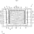
- FIG. 4 is a cross-sectional view taken along line A-A' shown in FIG. 1
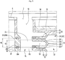
- FIG. 5 is an enlarged cross-sectional view of the portion B shown in FIG. 4
- FIG. 6 is a cross-sectional view taken along line C-C' shown in FIG. 1
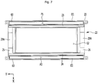
- FIG. 7 is a plan view of the cartridges shown in FIGS. 3-6
- FIG. 8 is a perspective view of the cartridges shown in FIGS. 3-6
- FIG. 9 is a perspective view when example cartridges and example battery cells are stacked and in contact with each other.
- the battery cells 10 may have the same configuration and the same configuration of the battery cells 10 is given reference number '10'.
- the upper battery cell is given reference numeral '10A' and the lower battery cell is given reference numeral '10B'.
- the uppermost battery cell is given reference numeral '10C' and the lowermost battery cell is given reference numeral '10D' in the following description.
- the uppermost battery cell 10C may be an upper battery cell for the battery cell positioned right under it and is given reference numeral '10C' for the convenience of description in the following description.
- the lowermost battery cell 10D may be a lower cartridge for the battery cell positioned right over it and is given reference numeral '10D' for the convenience of description in the following description.
- the battery cells 10 may be pouch type batteries.
- the battery cells 10 may each include an electrode assembly including an anode plate and a cathode plate, and a pouch 11 that may be made of aluminum or a laminate sheet of polymer resin and that may cover the electrode assembly.
- the pouch 11 may be formed by bonding a pair of sheets with the electrode assembly therebetween.
- the sheets may each have a cover portion 12 covering the outer side of the electrode assembly and a bonding portion 13 bending from the cover portion 12 to be bonded.
- the bonding portion 13 may be formed substantially in a rectangular ring shape.
- the outer side of the bonding portion 13 may be the outer side of the battery cell 10.
- the bonding portion 13 may horizontally protrude from the battery cell 10, and as shown in FIGS. 4 and 5 , it may be inserted and supported in the gap between two vertically adjacent cartridges 20.
- the battery cells are disposed in the spaces formed by the cartridges 20.
- the cartridges 20 may cover the fronts, rears, left sides, and right sides of the battery cells 10.
- the battery cells 10 are vertically arranged in contact with adjacent battery cells.
- the battery cells 10 are vertically adjacent to each other, and the bottom of the upper battery cell 10A may face the top of the lower battery cell 10B.
- the bottom of the upper battery cell 10A are seated on the top of the lower battery cell 10B and in contact with the top of the lower battery cell 10B.
- a separate cooling plate may not be provided between adjacent battery cells, and adjacent battery cells 10 are in contact with each other.
- the cartridges 20, as shown in FIG. 4 are stacked such that the ducts D1 and D2 communicate with the ducts of an adjacent cartridge.
- the ducts D1 and D2 of the cartridges 20 communicate with the ducts of an adjacent cartridge in the stacking direction of the cartridges 20 (in the Z-axial direction).
- the duct D1 and D2 of the cartridges 20 vertically communicate with the duct of an adjacent cartridge.
- the duct D1 and D2 of an upper cartridge 20A respectively communicate with the duct D1 and D2 of a lower cartridge 20B which is adjacent to the upper cartridge 20A and air can vertically pass through the duct D1 and D2 of the upper cartridge 20A and the duct D1 and D2 of the lower cartridge 20B.
- one cartridge 20 is in contact with at least one battery cell 10 and air can absorb heat of the battery cells 10 while sequentially passing through the ducts D1 and D2 of the cartridges 20.
- the cartridges 20 function as heat transmission members that can absorb heat from the battery cells 10 and transmit the heat to the air passing through the ducts D1 and D2.
- the cartridges 20 each may be made of a nonmetal in a body shape.
- the battery cell contact body 22 and the ducts D1 and D2 may be formed by one nonmetallic body.
- the material of the cartridges 20 may include a synthetic resin, for example, a plastic.
- the battery cell contact body 22 and the ducts D1 and D2 may be made of a synthetic resin, for example, a plastic.
- Heat of a battery cell 10 transfers to a battery cell contact body 22 that contacts the battery cell 10 and transfers to ducts D1 and D2 from the battery cell contact body 22.
- the heat transferring to the ducts D1 and D2, as described above, may transfer to the air passing through the ducts D1 and D2.
- Air can cool duct D1 and D2 while passing through the duct D1 and D2 and a cartridge 20 dissipates heat through a heat transfer path connected to the duct D1 and D2 from a battery cell contact body 22.
- the cartridges 20 cool the battery cells 10 without separate metallic cooling plates contacting the battery cells 10
- the cartridges 20 are heat dissipation cartridges.
- the cartridges 20 may be plastic heat dissipation cartridges.
- the cartridges 20 may be duct-integrated plastic heat dissipation cartridges.
- the cartridges 20 dissipate heat from the battery cells 10 using the duct D1 and D2 thereof without separate metallic cooling plates, the number of parts and the weight of the battery pack P can be reduced, as compared with a battery pack including specific metallic cooling plates. That is, the battery pack P can be made light.
- the height H1 of the duct D1 and D2 is greater than the height H2 of the battery cell contact body 22.
- the height of the upper end of the duct D1 and D2 may be greater than the height of the upper end of the battery cell contact body 22 and the duct D1 and D2 may protrude from the top of the cartridge 20.
- the lower end of the duct of an upper cartridge 20A may be seated on the upper end of the duct of a lower cartridge 20B which is adjacent to the upper cartridge 20A.
- the duct D1 and D2 of an upper cartridge 20A and the duct D1 and D2 of a lower cartridge 20B which is adjacent to the upper cartridge 20A may be in contact with each other.
- One duct or a plurality of ducts is formed at each of the cartridges 20.
- one duct is formed at each of the cartridges 20, and air can cool the cartridges 20 one time while passing through the cartridges 20.
- a plurality of ducts is formed at each of the cartridges 20, and air can remove the heat of the cartridges several times.
- Heat from a battery cell 10 can be horizontally transferred through the cartridge 20, and the ducts D1 and D2 of the cartridge 20 may be spaced from each other with the battery cell 10 therebetween.
- a pair of ducts may be spaced apart from each other at each of the cartridges, in which air can dissipate heat around any one D1 of ducts D1 and D2 while passing through the duct D1 and can dissipate heat around the other one D2 of the ducts D1 and D2 while passing through the duct D2.
- the heat transferring to both sides of the battery cell 10 from the battery cell 10 can be distributed and dissipated through the ducts D1 and D2.
- the pair of ducts D1 and D2 may be spaced from each other at each of the cartridges 20.
- the ducts D1 and D2 may be formed such that a battery cell space S2 for keeping a battery cell 10 may be formed within a battery cell contact body 22.
- the ducts D1 and D2 may be spaced from each other with the battery cell space S2 therebetween.
- the ducts of upper cartridges 20A and the ducts of lower cartridges 20B vertically communicate with each other, so the cartridges 20 form vertically long air passages.
- a first duct D1 and a second duct D2 may be formed at each of the cartridges 20.
- a vertically long first air passage P1 may be formed by the first ducts D1 of the cartridges 20 that vertically communicate with each other.
- another vertically long second air passage P2 may be formed by the second ducts D2 of the cartridges 20 that vertically communicate with each other.
- the first air passage P1 and the second air passage P2 may be open in parallel with each other with the battery cells 10 therebetween.
- the first air passage P1 formed by the first ducts D1 of the cartridges 20 may be positioned under the outer intake hole 2 shown in FIG. 1 .
- the first air passage P1 formed by the first ducts D1 may function as an intake heat dissipation channel for air to primarily or initially cool the cartridges 20.
- the second air passage formed by the second ducts D2 of the cartridges 20 may be positioned under the outer exhaust hole 3 shown in FIG. 1 .
- the second air passage P2 formed by the second ducts D2 may function as an exhaust heat dissipation channel for air to secondarily or subsequently cool the cartridges 20.
- a battery cell contact body 22 is described in detail with reference to FIGS. 7 to 9 .
- An open battery cell space S2 that may receive a battery cell 10 may be formed inside the battery cell contact body 22.
- the battery cell contact body 22 may surround and protect the edges of the battery cell 10.
- the battery cell space S2 may be open at the top and bottom.
- the battery cell contact body 22 has a pair of contact portions 23 and 24 protruding from the ducts D1 and D2 and a pair of bridges 25 and 26 connecting the contact portions 23 and 24.
- the battery cell contact body 22 may be formed in a rectangular ring frame shape, which may be defined by the contact portions 23 and 24 and the bridges 25 and 26.
- the contact portions 23 and 24 may protrude horizontally from sides of the ducts D1 and D2.
- the contact portions 23 and 24 may be spaced from each other in a width direction or the spacing direction of the ducts D1 and D2 (in the X-axial direction).
- the contact portions 23 and 24 may include a first contact portion 23 protruding from the first duct D1 and a second contact portion 24 protruding from the second duct D2.
- the first contact portion 23 and the second contact portion 24 may be spaced from each other in the left-right direction or in the front-rear direction.
- the first contact portion 23 may protrude toward the second duct D2 from the side, which faces the second duct D2, of four sides of the first duct D1.
- the second contact portion 24 may protrude toward the first duct D1 from the side, which faces the first duct D1, of four sides of the second duct D2.
- the contact portions 23 and 24 may be symmetrically formed with the battery cell space S2 therebetween.
- the contact portions 23 and 24 may each have one or more inclined portions 22A and 22B and horizontal portions 22C and 22D connecting the inclined portion 22A and the ducts D1 and D2.
- the contact portions 23 and 24 may include a pair of inclined portions 22A and 22B that are inclined in opposite directions and connected to each other at ends.
- Vertical cross-section views of the inclined portions 22A and 22B may include a '>' shape.
- the inclined portions 22A and 22B are in contact with different battery cells 10.
- the upper inclined portion 22A may be in contact with an upper battery cell 10A and the lower inclined portion 22B may be in contact with a lower battery cell 10B.
- the contact portions 23 and 24 are in contact with a pair of battery cells 10A and 10B, respectively, and the battery cell contact body 22 receives heat from the battery cells.
- the contact portions 23 and 24 each may further have an upper horizontal portion 22C that horizontally extends from the upper end of the upper inclined portion 22A of the inclined portions 22A and 22B and is connected to the ducts D1 and D2.
- the contact portions 23 and 240 each may further have a lower horizontal portion 22D that horizontally extends from the lower end of the lower inclined portion 22B of the inclined portions 22A and 22B and is connected to the ducts D1 and D2.
- a gap S3 through which air flowing through the ducts D1 and D2 can flow inside and outside may be formed between the upper horizontal portion 22C and the lower horizontal portion 22D.
- Some of the air vertically passing through the ducts D1 and d2 may flow into the gap S3 and directly absorb heat of the inclined portions 22A and 22B, so the air cooling effect can be increased.
- the contact portions 23 and 24 each has both of the upper horizontal portion 22C and the lower horizontal portion 22D. In some implementations, the contact portions 23 and 24 may have one of the upper horizontal portion 22C or the lower horizontal portion 22D.
- the upper horizontal portion 22C and the lower horizontal portion 22D may function as heat transmission portions that can transmit heat has been transferred from battery cells 10 to the inclined portions 22A and 22B and to the ducts D1 and D2.
- the bonding portion 13 of a pouch 11 may be fitted between the lower horizontal portion 22D of an upper cartridge 20A and the upper horizontal portion 22C of a lower cartridge 20B which is adjacent to the upper cartridge 20A.
- the bonding portion 13 of the pouch 11 may be in surface contact with the lower horizontal portion 22D on the top and the upper horizontal portion 22C on the bottom, the lower horizontal portion 22D and the upper horizontal portion 22C may receive heat from the bonding portion 13 of the pouch 11, and the heat of battery cells 10 can more quickly transfer to the ducts D1 and D2.
- the bridges 25 and 26 may be spaced from each other perpendicular to the spacing direction of the ducts D1 and D2 (in the Y-axial direction).
- the bridges 25 and 26 may be spaced from each other in the Y-axial direction perpendicular to the spacing direction of the contact portions 23 and 24 (the X-axial direction) without being in direct contact with the ducts D1 and D2.
- the base 40 is described hereafter.
- the lowermost cartridge 20D of the cartridges may be seated on the base 40, as shown in FIG. 4 .
- a return channel 42 connecting the ducts D1 and D2 of the lowermost cartridge 20D may be formed in the base 40.
- the return channel 42 may have an inlet 43 positioned under any one of the ducts D1 or D2 of the lowermost cartridge, an outlet 44 positioned under the other one of the ducts D1 and D2 of the lowermost cartridge, and a connection channel 45 connecting the inlet 43 and the outlet 44.
- a recessed seat 46 where the lowermost battery cell disposed inside the lowermost cartridge 20D is seated may be formed on the top of the base 40.
- the lowermost battery cell 10D in the lowermost cartridge 20D is a battery cell that is positioned lowest of the battery cells and the bottom of the lowermost battery cell 10D may be inserted in the seat 46 with the top of the edge in contact with the battery cell contact body 22 of the lowermost cartridge 20A. The bottom of the lowermost battery cell 10D may be in contact with the seat 46.
- the top plate 50 is described hereafter.
- the top plate 50 may have an upper intake duct 51 that can communicate with any one of the ducts D1 and D2 of the uppermost cartridge 20C and an upper exhaust duct 52 that can communicate with the other one of the ducts D1 and D2 of the uppermost cartridge 20C.
- the upper intake duct 51 and the upper exhaust duct 52 of the top plate 50 may have the same shape as the ducts of the uppermost cartridge 20C.
- the top plate 50 may further have a cover plate 53 that connects the upper intake duct 51 and the upper exhaust duct 62 and covers the top of the uppermost battery cell 10C in the uppermost cartridge 20C.
- the upper intake duct 51 may be positioned between the first duct D1 of the uppermost cartridge 20C and the top of the upper case 6 and can guide the air flowing inside through the outer intake hole 2 of the upper case 6 into the first duct D1 of the uppermost cartridge 20C.
- the upper exhaust duct 52 may be positioned between the second duct D2 of the uppermost cartridge 20C and the top of the upper case 6 and can guide the air that has passed through the second duct D2 of the uppermost cartridge 20C into the outer exhaust hole 3.
- the battery pack P may further include a pressing plate 56 coupled to the top plate 50 to press the top plate 50 to the uppermost battery cell 10C.
- the outer intake hole 2 of the upper case 6 may be positioned over the upper intake duct 51.
- the outer exhaust hole 3 of the upper case 6 may be positioned over the upper exhaust duct 52.
- the air that has passed through the outer intake hole 2 can pass through the upper intake duct 51 of the top plate 50 and then flow into any one D1 of the ducts D1 and D2 of the uppermost cartridge 20C.
- the air that has passed through any one D1 of the ducts D1 and D2 of the uppermost cartridge 20C can pass through the upper exhaust duct 52 of the top plate 50 and then pass through the outer exhaust hole 3.
- the entire channel for air that cools the battery cells may be formed by the first air passage P1 elongated downward in the battery pack P, the return channel 42 connected to the lower end of the first air passage P1 and horizontally elongated under the lowermost battery cell 10, and the second air passage P2 connected to the return channel 42 and elongated upward in the battery pack P.
- the overall air channel formed by the first air passage P1, the return channel 42, and the second air passage P2 may have a U-shape and cover the left and right sides of the area where the battery cells are disposed.
- the battery pack P is configured such that the gas G discharged from the battery cells 10 does not flow into the air passages P1 and P2. In this case, it is possible to prevent the gas G from flowing into the interior of a vehicle through the air passages P1 and P2 and the exhaust ducts.
- a gas exhaust passage 29 for discharging the gas from the battery cells 10 may be formed between adjacent cartridges 20.
- the gas exhaust passages 29 may be open in the Y-axial direction perpendicular to the opening direction of the ducts D1 and D2 (the Z-axial direction).
- the gas from the battery cell 10 may be horizontally discharged.
- the battery cells 10 each may have protrusive cell leads 18.
- the cell leads 18, as shown in FIG. 9 may protrude from sides 15 perpendicular to the sides 14 facing ducts D1 and D2 of the edges of a battery cell 10.
- the cell leads 18 may be formed on the sides 14, which face ducts D1 and D2, of each battery cell 10.
- the cartridges 20 each may have seating grooves 29A and 29B for receiving cell leads 18.
- the gas exhaust passage 29 may be formed between the seating groove 29B of an upper cartridge 20A of adjacent cartridges 20 and the seating groove 29A of the lower cartridge 20B.
- a gap T through which air that has passed out of the gas exhaust passage 29 can flow may be formed between the inner cover 70 and the battery cells 10 and the gas G in the gap can flow out of the outer gas exhaust hole 4 after sequentially passing through the inner gas exhaust hole 72 of the inner cover 70 and between the inner cover 70 and the outer case.
- the battery pack P may further include at least one sealing member 60.
- the sealing members 60 can seal the portions between the ducts D1 and D2 of an upper cartridge 20A and the ducts D1 and D2 of a lower cartridge 20B which is adjacent to the upper cartridge 20A.
- the gas that has sequentially passed through the gas exhaust passage 29 and the gas exhaust hole 72 can pass between the inner cover 70 and the outer case 1, and when the gas flows into the gaps between the ducts D1 and D2 of adjacent cartridges 20, the gas may flow into the air passages P1 and P2.
- the sealing members 60 can prevent the gas G from flowing inside between ducts D1 and D2 that vertically communicate with each other and the channels P1, P2, and 42 through which air passes in the battery pack P can be separated from the channels through which gas can flow in the battery pack P.
- Sealing member grooves 28A and 28B in which the sealing members 60 are inserted may be formed on the top and bottom of each of the cartridges 20.
- the sealing members 60 may be formed in a rectangular ring shape larger than the ducts D1 and D2, and in this case, one sealing member can seal a duct.
- one cartridge may have two ducts D1 and D2, and two sealing members 60 may be provided for one cartridge.
Description
- The present disclosure relates to a battery pack, and for example, to a battery pack including cartridges and battery cells.
- A battery pack is a device that can be assembled from a plurality of battery cells and that can supply power to other devices connected to the battery pack. A battery pack can be used in various industrial fields and various devices, such as mobile phones, home appliances, and vehicles.
- For example, a battery pack may be mounted and used in electric vehicles that can be driven by the power from a driving motor, and the battery pack may include a plurality of battery cells and a plurality of cartridges that are configured to receive the battery cells.
- The battery pack may further include cooling plates for dissipating heat from the battery cells. The cooling plates may be in contact with the battery cells and can absorb heat from the battery cells.
- In some cases, the battery pack may include the cooling plates made of a metallic material with a high thermal conductivity, such as aluminium. In these cases, the cooling plates may increase the weight of the battery pack.
-
JP 2008 103248 A -
EP 1 577 966 A2 -
US 2012/0040222 A1 discloses a molded cooling fin and frame, including center cooling fins and outer cooling fins. The cooling fins and frames are included into a battery pack. -
EP 1 744 383 A1 - One of the objects of the present disclosure is to provide a battery pack that includes a relatively small number of parts, that is light, and that is able to cool a plurality of cartridges using air.
- Another object of the present disclosure is to provide a battery pack that can be made in a compact form factor.
- The scope of protection is defined by the appended claims. Features describing details of further embodiments are defined in the dependent claims. Subject matter not covered by the claims is not according to the invention.
- According to the subject matter described in this application, a battery pack includes a plurality of cartridges that are stackable in a vertical direction in which each cartridge of the plurality of cartridges extends in a longitudinal direction perpendicular to the vertical direction and a plurality of battery cells that are vertically arranged in contact with adjacent battery cells, wherein each battery cell is disposed in a cartridge of the plurality of cartridges. Each cartridge of the plurality of cartridges includes a battery cell contact body that is configured to contact a battery cell of the plurality of battery cells and support the battery cell, and at least one duct that is configured to transmit heat from the battery cell contact body to air by passing air through the at least one duct. Each duct of the plurality of cartridges is configured to communicate air with another duct of an adjacent cartridge. The battery cell contact body includes: a pair of contact portions protruding from the ducts and a pair of bridges connecting the contact portions, wherein the contact portions are in contact with a pair of battery cells, such that the battery cell contact body can receive heat from the battery cells.
- Implementations according to this aspect may include one or more of following features. The battery cell contact body and the duct may be integrally formed of a non-metallic material, and the duct may protrude upward relative to the battery cell contact body. The battery cell may have an upper surface that contacts a lower surface of an adjacent battery cell stacked above the battery cell.
- In some implementations, each duct of the plurality of cartridges may have a lower end and an upper end, the upper end being configured to seat a lower end of a duct from an adjacent cartridge, and each duct of the plurality of cartridges may be configured to vertically communicate air with ducts of adjacent cartridges that are stacked above and below. Each cartridge of the plurality of cartridges may include a pair of ducts that are spaced apart from each other in a width direction perpendicular to the longitudinal direction.
- In some implementations, the battery cell contact body may be configured to receive the battery cell in a battery cell space defined between the pair of ducts. The battery cell contact body includes: a pair of contact portions that protrude from a side surface of the pair of ducts, the pair of contact portions being spaced apart from each other in the width direction and extending in the longitudinal direction; and a pair of bridges that connect the pair of contact portions to each other, the pair of bridges being spaced apart from each other in the longitudinal direction and extending in the width direction.
- In some implementations, the battery pack may further include a base that defines a return channel configured to communicate with a pair of ducts of a lowermost cartridge. The return channel may include an inlet positioned under a first duct of the pair of ducts of the lowermost cartridge, an outlet positioned under a second duct of the pair of ducts of the lowermost cartridge, and a connection channel connecting the inlet to the outlet. The base may be configured to seat the pair of ducts of the lowermost cartridge. In some examples, the base may define a recessed seat configured to receive a lowermost battery cell that is disposed in the lowermost cartridge.
- In some implementations, the battery pack may further include a top plate disposed vertically above an uppermost cartridge in which the top plate includes: an upper intake duct that is configured to communicate with a first duct of the pair of ducts of the uppermost cartridge, and an upper exhaust duct that is configured to communicate with a second duct of the pair of ducts of the uppermost cartridge. In some examples, the top plate may further include a cover plate that extends from the upper intake duct to the upper exhaust duct and that covers at least a portion of an uppermost battery cell disposed in the uppermost cartridge.
- In some implementations, the battery pack may further include a pressing plate that is coupled to the top plate and configured to provide a pressure to the top plate and to the uppermost cartridge. In some implementations, the battery pack may further include a lower case, and an upper case that covers a top portion of the lower case in which the upper case defines an outer intake hole located vertically above the upper intake duct, and an outer exhaust hole located vertically above the upper exhaust duct.
- In some implementations, the battery pack may further include gas exhaust passages, each of the gas exhaust passages being defined between adjacent cartridges and configured to discharge gas from the battery cells in a direction perpendicular to an opening direction of the duct. In some examples, each of the battery cells may include cell leads that protrude in the longitudinal direction, each cartridge of the plurality of cartridges may include seating grooves that are configured to receive the cell leads, and the gas exhaust passages are defined between the seating grooves of the adjacent cartridges.
- In some implementations, the battery pack may further include an inner cover that faces predetermined sides of the plurality of cartridges. In some cases, the inner cover may be spaced apart from the predetermined sides of the plurality of cartridges to thereby define a gap that allows flow of gas that has passed through the gas exhaust passages, and the inner cover may define an inner gas exhaust hole that is configured to discharge the gas from the gap.
- In some implementations, the battery pack may further include one or more sealing members that are configured to provide a seal between the ducts of the plurality of cartridges based on the plurality of cartridges being stacked. In some examples, each cartridge of the plurality of cartridges may define sealing member grooves on top and bottom surfaces of the cartridge, the sealing member grooves being configured to receive the sealing members.
-
-
FIG. 1 is a perspective view showing an example battery pack. -
FIG. 2 is an exploded perspective view of the example battery pack shown inFIG. 1 . -
FIG. 3 is an exploded perspective view showing example battery cells and example cartridge. -
FIG. 4 is a cross-sectional view taken along line A-A' shown inFIG. 1 . -
FIG. 5 is an enlarged cross-sectional view of the portion B shown inFIG. 4 . -
FIG. 6 is a cross-sectional view taken along line C-C' shown inFIG. 1 . -
FIG. 7 is a top view of the example cartridges shown inFIGS. 3-6 . -
FIG. 8 is a perspective view of the example cartridges shown inFIGS. 3-6 . -
FIG. 9 is a perspective view showing example cartridges and example battery cells that are stacked and in contact with each other. -
FIG. 1 is a perspective view showing an example battery pack,FIG. 2 is an exploded perspective view of the example battery pack shown inFIG. 1 , andFIG. 3 is an exploded perspective view showing example battery cells and example cartridges. - A battery pack may include an
outer case 1 that forms the external appearance. - An
outer intake hole 2 through which air for cooling the inside the battery pack P flows into theouter case 1 may be formed at theouter case 1. Anouter exhaust hole 3 through which the air that has cooled the inside of the battery pack P is discharged out of the battery pack P may be formed at theouter case 1. - The battery pack P may be installed in a vehicle and may be mounted on the car body of a vehicle, for instance.
- The battery pack P may be connected with an HVAC (Heating Ventilation Air Conditioning), or the inside or the outside of a vehicle through a duct.
- For example, the battery pack P may be connected to an HVAC or an interior of a vehicle through an intake duct and an exhaust duct, in which the air from the intake duct can flow into the battery pack P through the
outer intake hole 2 and remove the heat inside the battery pack P and the air in the battery pack P can be discharged out of the HVAC or the interior of the vehicle through theouter exhaust hole 3 and the exhaust duct. - In this case, the intake duct may be connected to the battery pack P to guide air into the
outer intake hole 2 and the exhaust duct may be connected to the battery pack P to guide the air discharged out of theouter exhaust hole 3. - The intake duct may have an end connected to a portion around the
outer intake hole 2 and the exhaust duct may have an end connected to a portion around theouter exhaust hole 3. - An outer
gas exhaust hole 4 through which gas G discharged from battery cells in the battery pack P is discharged out of the battery pack P may be formed at theouter case 1. - The
outer case 1 may have various shapes such as a polygonal shape, a hexahedron shape, and a round shape. - In some implementations, the
outer intake hole 2 and theouter exhaust hole 3 may be formed through a side of theouter case 1 and the outergas exhaust hole 4 may be formed through any one of sides of theouter case 1 except for the side with theouter intake hole 2 and theouter exhaust hole 3. - The
outer intake hole 2 and theouter exhaust hole 3 may be open in parallel with each other. - The outer
gas exhaust hole 4 may be open in a different direction from theouter intake hole 2 and theouter exhaust hole 3. - For example, the
outer intake hole 2 and theouter exhaust hole 3 may be open vertically in the outer case 1 (in the Z-axial direction), while the outergas exhaust hole 4 may be open horizontally in the outer case 1 (in the Y-axial direction). - In some implementations, the
outer intake hole 2 and theouter exhaust hole 3 may be open horizontally in theouter case 1, while the outergas exhaust hole 4 may be open vertically in theouter case 1. - In some implementations, all of the
outer intake hole 2, theouter exhaust hole 3, and the outergas exhaust hole 4 may be horizontally open. In these cases, theouter intake hole 2 and theouter exhaust hole 3 may be open in the left-right direction (in the X-axial direction), while the outergas exhaust hole 4 may be open in the front-rear direction (in the Y-axial direction). In other examples, theouter intake hole 2 and theouter exhaust hole 3 may be open in the front-rear direction (in the Y-axial direction), while the outergas exhaust hole 4 may be open in the left-right direction (in the X-axial direction). - The
outer case 1 may be an assembly of a plurality of members and may include alower case 5 and anupper case 6 covering the top of thelower case 5. - A
battery module 8 may be disposed in theouter case 1. - The outer
gas exhaust hole 4 may be formed at thelower case 5, and theouter intake hole 2 and theouter exhaust hole 3 may be formed at theupper case 6. - The
lower case 5 may be formed in a box shape with an open top. A space S1 that is open upward may be formed inside thelower case 5 and thebattery module 8 may be partially or entirely inserted and kept in the space S1 of thelower case 5. - The
battery module 8 includes a plurality ofbattery cells 10 and a plurality ofcartridges 20. - The
battery cells 10 are mounted on thecartridges 20. Thebattery cells 10 are vertically stacked on thecartridges 20. - The
battery cells 10 are vertically arranged to face adjacent battery cells. - The
cartridges 20 are stacked. Thecartridges 20 are vertically arranged to faceadjacent cartridges 20. - The
cartridges 20 are the same in shape and size and the common configurations of thecartridges 20 are given reference numeral '20' in the following description. - Further, of two adjacent cartridges, the upper cartridge is given reference numeral '20A' and the lower cartridge which is adjacent to the upper cartridge is given reference numeral '20B' in the following description.
- Further, of the
cartridges 20, the uppermost cartridge is given reference numeral '20C' and the lowermost cartridge is given reference numeral '20D' in the following description. - The
uppermost cartridge 20C may be an upper cartridge for the cartridge positioned right under it and is given reference numeral '20C' for the convenience of description in the following description. - Further, the
lowermost cartridge 20D may be a lower cartridge for the cartridge positioned right over it and is given reference numeral '20D' for the convenience of description in the following description. - The bottom of an
upper cartridge 20A is facing the top of alower cartridge 20B which is adjacent to theupper cartridge 20A. The lower end of anupper cartridge 20A may be seated on the upper end of alower cartridge 20B which is adjacent to theupper cartridge 20A. - The
cartridges 20 each include a batterycell contact body 22 that is in contact with abattery cell 10 and one or more ducts D1 and D2 for transmitting heat of the batterycell contact body 22 to air passing through it. - The
battery module 8 may include abase 40. The base 40 may form the external appearance of the bottom of thebattery module 8. Thelowermost cartridge 20D of thecartridges 20 may be disposed on thebase 40 and the weight of thecartridges 20 may be applied to thebase 40. - The
battery module 8 may further include atop plate 50. Thetop plate 50 may be disposed over theuppermost cartridge 20C. Thetop plate 50 can cover the top of theuppermost cartridge 20C and the top of the uppermost battery cell in theuppermost cartridge 20C. - The battery pack P may include a
membrane 9 disposed in the outergas exhaust hole 4. Themembrane 9 can prevent foreign substances from flowing inside through the outergas exhaust hole 4. Themembrane 9 may be breakable to relieve an internal air pressure when the internal pressure of the battery pack P exceeds a reference pressure. When themembrane 9 breaks, high-pressure fluid in the battery pack P may leak out of the battery pack P through the outergas exhaust hole 4. - The battery pack P may include
inner covers cartridges 20. The inner covers 70 and 71 may be provided in pairs inside theouter case 1. The inner covers 70 and 71 may be spaced apart from each other with thecartridges 20 therebetween and thecartridges 20 may be protected by the inner covers 70 and 71. - An inner
gas exhaust hole 72 for passing gas G discharged from thebattery cells 10 may be formed at any one 70 of the inner covers 70 and 71. The gas G discharged from thebattery cells 10 may pass through the innergas exhaust hole 72 and then may be discharged outside through the outergas exhaust hole 4. -
FIG. 4 is a cross-sectional view taken along line A-A' shown inFIG. 1 ,FIG. 5 is an enlarged cross-sectional view of the portion B shown inFIG. 4 ,FIG. 6 is a cross-sectional view taken along line C-C' shown inFIG. 1 ,FIG. 7 is a plan view of the cartridges shown inFIGS. 3-6 ,FIG. 8 is a perspective view of the cartridges shown inFIGS. 3-6 , andFIG. 9 is a perspective view when example cartridges and example battery cells are stacked and in contact with each other. - The
battery cells 10 may have the same configuration and the same configuration of thebattery cells 10 is given reference number '10'. - Further, of two adjacent battery cells, the upper battery cell is given reference numeral '10A' and the lower battery cell is given reference numeral '10B'.
- Further, of the
battery cells 10, the uppermost battery cell is given reference numeral '10C' and the lowermost battery cell is given reference numeral '10D' in the following description. - The
uppermost battery cell 10C may be an upper battery cell for the battery cell positioned right under it and is given reference numeral '10C' for the convenience of description in the following description. - Further, the
lowermost battery cell 10D may be a lower cartridge for the battery cell positioned right over it and is given reference numeral '10D' for the convenience of description in the following description. - In some implementations, the
battery cells 10 may be pouch type batteries. Thebattery cells 10 may each include an electrode assembly including an anode plate and a cathode plate, and apouch 11 that may be made of aluminum or a laminate sheet of polymer resin and that may cover the electrode assembly. - In some implementations, the
pouch 11 may be formed by bonding a pair of sheets with the electrode assembly therebetween. - The sheets may each have a
cover portion 12 covering the outer side of the electrode assembly and abonding portion 13 bending from thecover portion 12 to be bonded. - The
bonding portion 13 may be formed substantially in a rectangular ring shape. The outer side of thebonding portion 13 may be the outer side of thebattery cell 10. - The
bonding portion 13 may horizontally protrude from thebattery cell 10, and as shown inFIGS. 4 and5 , it may be inserted and supported in the gap between two verticallyadjacent cartridges 20. - The battery cells are disposed in the spaces formed by the
cartridges 20. Thecartridges 20 may cover the fronts, rears, left sides, and right sides of thebattery cells 10. - The
battery cells 10 are vertically arranged in contact with adjacent battery cells. - The
battery cells 10 are vertically adjacent to each other, and the bottom of theupper battery cell 10A may face the top of thelower battery cell 10B. - Further, the bottom of the
upper battery cell 10A are seated on the top of thelower battery cell 10B and in contact with the top of thelower battery cell 10B. - In some implementations, a separate cooling plate may not be provided between adjacent battery cells, and
adjacent battery cells 10 are in contact with each other. - When
adjacent battery cells 10 are vertically arranged in contact with each other without a separate cooling plate between adjacent battery cells, the overall height of the battery pack P is reduced and the battery pack P is made compact. - The
cartridges 20, as shown inFIG. 4 , are stacked such that the ducts D1 and D2 communicate with the ducts of an adjacent cartridge. The ducts D1 and D2 of thecartridges 20 communicate with the ducts of an adjacent cartridge in the stacking direction of the cartridges 20 (in the Z-axial direction). - The duct D1 and D2 of the
cartridges 20 vertically communicate with the duct of an adjacent cartridge. - The duct D1 and D2 of an
upper cartridge 20A respectively communicate with the duct D1 and D2 of alower cartridge 20B which is adjacent to theupper cartridge 20A and air can vertically pass through the duct D1 and D2 of theupper cartridge 20A and the duct D1 and D2 of thelower cartridge 20B. - In some implementations, one
cartridge 20 is in contact with at least onebattery cell 10 and air can absorb heat of thebattery cells 10 while sequentially passing through the ducts D1 and D2 of thecartridges 20. - The
cartridges 20 function as heat transmission members that can absorb heat from thebattery cells 10 and transmit the heat to the air passing through the ducts D1 and D2. - The
cartridges 20 each may be made of a nonmetal in a body shape. The batterycell contact body 22 and the ducts D1 and D2 may be formed by one nonmetallic body. - The material of the
cartridges 20 may include a synthetic resin, for example, a plastic. The batterycell contact body 22 and the ducts D1 and D2 may be made of a synthetic resin, for example, a plastic. - Heat of a
battery cell 10 transfers to a batterycell contact body 22 that contacts thebattery cell 10 and transfers to ducts D1 and D2 from the batterycell contact body 22. The heat transferring to the ducts D1 and D2, as described above, may transfer to the air passing through the ducts D1 and D2. - Air can cool duct D1 and D2 while passing through the duct D1 and D2 and a
cartridge 20 dissipates heat through a heat transfer path connected to the duct D1 and D2 from a batterycell contact body 22. - In some implementations, the
cartridges 20 cool thebattery cells 10 without separate metallic cooling plates contacting thebattery cells 10 Thecartridges 20 are heat dissipation cartridges. When the material of thecartridges 20 is plastic, thecartridges 20 may be plastic heat dissipation cartridges. Thecartridges 20 may be duct-integrated plastic heat dissipation cartridges. - In these implementations, since the
cartridges 20 dissipate heat from thebattery cells 10 using the duct D1 and D2 thereof without separate metallic cooling plates, the number of parts and the weight of the battery pack P can be reduced, as compared with a battery pack including specific metallic cooling plates. That is, the battery pack P can be made light. - Referring to
FIG. 5 , the height H1 of the duct D1 and D2 is greater than the height H2 of the batterycell contact body 22. The height of the upper end of the duct D1 and D2 may be greater than the height of the upper end of the batterycell contact body 22 and the duct D1 and D2 may protrude from the top of thecartridge 20. - The lower end of the duct of an
upper cartridge 20A may be seated on the upper end of the duct of alower cartridge 20B which is adjacent to theupper cartridge 20A. - The duct D1 and D2 of an
upper cartridge 20A and the duct D1 and D2 of alower cartridge 20B which is adjacent to theupper cartridge 20A may be in contact with each other. - One duct or a plurality of ducts is formed at each of the
cartridges 20. - In some implementations, one duct is formed at each of the
cartridges 20, and air can cool thecartridges 20 one time while passing through thecartridges 20. - In some implementations, a plurality of ducts is formed at each of the
cartridges 20, and air can remove the heat of the cartridges several times. - Heat from a
battery cell 10 can be horizontally transferred through thecartridge 20, and the ducts D1 and D2 of thecartridge 20 may be spaced from each other with thebattery cell 10 therebetween. - In some implementations, a pair of ducts may be spaced apart from each other at each of the cartridges, in which air can dissipate heat around any one D1 of ducts D1 and D2 while passing through the duct D1 and can dissipate heat around the other one D2 of the ducts D1 and D2 while passing through the duct D2.
- When a pair of ducts D1 and D2 is formed at a
cartridge 20, the heat transferring to both sides of thebattery cell 10 from thebattery cell 10 can be distributed and dissipated through the ducts D1 and D2. The pair of ducts D1 and D2 may be spaced from each other at each of thecartridges 20. - In some implementations, the ducts D1 and D2 may be formed such that a battery cell space S2 for keeping a
battery cell 10 may be formed within a batterycell contact body 22. - The ducts D1 and D2 may be spaced from each other with the battery cell space S2 therebetween.
- Regarding the
cartridges 20, the ducts ofupper cartridges 20A and the ducts oflower cartridges 20B vertically communicate with each other, so thecartridges 20 form vertically long air passages. - A first duct D1 and a second duct D2 may be formed at each of the
cartridges 20. A vertically long first air passage P1 may be formed by the first ducts D1 of thecartridges 20 that vertically communicate with each other. - Further, another vertically long second air passage P2 may be formed by the second ducts D2 of the
cartridges 20 that vertically communicate with each other. - The first air passage P1 and the second air passage P2 may be open in parallel with each other with the
battery cells 10 therebetween. - The first air passage P1 formed by the first ducts D1 of the
cartridges 20 may be positioned under theouter intake hole 2 shown inFIG. 1 . In this case, the first air passage P1 formed by the first ducts D1 may function as an intake heat dissipation channel for air to primarily or initially cool thecartridges 20. - Further, the second air passage formed by the second ducts D2 of the
cartridges 20 may be positioned under theouter exhaust hole 3 shown inFIG. 1 . In this case, the second air passage P2 formed by the second ducts D2 may function as an exhaust heat dissipation channel for air to secondarily or subsequently cool thecartridges 20. - A battery
cell contact body 22 is described in detail with reference toFIGS. 7 to 9 . - An open battery cell space S2 that may receive a
battery cell 10 may be formed inside the batterycell contact body 22. - The battery
cell contact body 22 may surround and protect the edges of thebattery cell 10. The battery cell space S2 may be open at the top and bottom. - The battery
cell contact body 22 has a pair ofcontact portions bridges contact portions - In some implementations, the battery
cell contact body 22 may be formed in a rectangular ring frame shape, which may be defined by thecontact portions bridges - The
contact portions contact portions - The
contact portions first contact portion 23 protruding from the first duct D1 and asecond contact portion 24 protruding from the second duct D2. - The
first contact portion 23 and thesecond contact portion 24 may be spaced from each other in the left-right direction or in the front-rear direction. - The
first contact portion 23 may protrude toward the second duct D2 from the side, which faces the second duct D2, of four sides of the first duct D1. - Further, the
second contact portion 24 may protrude toward the first duct D1 from the side, which faces the first duct D1, of four sides of the second duct D2. - The
contact portions - Referring to
FIGS. 5 and8 , thecontact portions inclined portions horizontal portions inclined portion 22A and the ducts D1 and D2. - The
contact portions inclined portions - Vertical cross-section views of the
inclined portions - The
inclined portions different battery cells 10. For example, referring toFIG. 5 , of a pair ofinclined portions inclined portion 22A may be in contact with anupper battery cell 10A and the lowerinclined portion 22B may be in contact with alower battery cell 10B. - That is, the
contact portions battery cells cell contact body 22 receives heat from the battery cells. - The
contact portions horizontal portion 22C that horizontally extends from the upper end of the upperinclined portion 22A of theinclined portions - The
contact portions 23 and 240 each may further have a lowerhorizontal portion 22D that horizontally extends from the lower end of the lowerinclined portion 22B of theinclined portions - When the
contact portions horizontal portion 22C and the lowerhorizontal portion 22D, as shown inFIG. 5 , a gap S3 through which air flowing through the ducts D1 and D2 can flow inside and outside may be formed between the upperhorizontal portion 22C and the lowerhorizontal portion 22D. - Some of the air vertically passing through the ducts D1 and d2 may flow into the gap S3 and directly absorb heat of the
inclined portions - In these implementations, the
contact portions horizontal portion 22C and the lowerhorizontal portion 22D. In some implementations, thecontact portions horizontal portion 22C or the lowerhorizontal portion 22D. - The upper
horizontal portion 22C and the lowerhorizontal portion 22D may function as heat transmission portions that can transmit heat has been transferred frombattery cells 10 to theinclined portions - The
bonding portion 13 of apouch 11 may be fitted between the lowerhorizontal portion 22D of anupper cartridge 20A and the upperhorizontal portion 22C of alower cartridge 20B which is adjacent to theupper cartridge 20A. - The
bonding portion 13 of thepouch 11 may be in surface contact with the lowerhorizontal portion 22D on the top and the upperhorizontal portion 22C on the bottom, the lowerhorizontal portion 22D and the upperhorizontal portion 22C may receive heat from thebonding portion 13 of thepouch 11, and the heat ofbattery cells 10 can more quickly transfer to the ducts D1 and D2. - The
bridges - The
bridges contact portions 23 and 24 (the X-axial direction) without being in direct contact with the ducts D1 and D2. - The
base 40 is described hereafter. - The
lowermost cartridge 20D of the cartridges may be seated on thebase 40, as shown inFIG. 4 . Areturn channel 42 connecting the ducts D1 and D2 of thelowermost cartridge 20D may be formed in thebase 40. - The
return channel 42 may have aninlet 43 positioned under any one of the ducts D1 or D2 of the lowermost cartridge, anoutlet 44 positioned under the other one of the ducts D1 and D2 of the lowermost cartridge, and aconnection channel 45 connecting theinlet 43 and theoutlet 44. - A recessed
seat 46 where the lowermost battery cell disposed inside thelowermost cartridge 20D is seated may be formed on the top of thebase 40. - The
lowermost battery cell 10D in thelowermost cartridge 20D is a battery cell that is positioned lowest of the battery cells and the bottom of thelowermost battery cell 10D may be inserted in theseat 46 with the top of the edge in contact with the batterycell contact body 22 of thelowermost cartridge 20A. The bottom of thelowermost battery cell 10D may be in contact with theseat 46. - The
top plate 50 is described hereafter. - The
top plate 50, as shown inFIG. 4 , may have anupper intake duct 51 that can communicate with any one of the ducts D1 and D2 of theuppermost cartridge 20C and anupper exhaust duct 52 that can communicate with the other one of the ducts D1 and D2 of theuppermost cartridge 20C. - In some implementations, the
upper intake duct 51 and theupper exhaust duct 52 of thetop plate 50 may have the same shape as the ducts of theuppermost cartridge 20C. - The
top plate 50 may further have acover plate 53 that connects theupper intake duct 51 and the upper exhaust duct 62 and covers the top of theuppermost battery cell 10C in theuppermost cartridge 20C. - The
upper intake duct 51 may be positioned between the first duct D1 of theuppermost cartridge 20C and the top of theupper case 6 and can guide the air flowing inside through theouter intake hole 2 of theupper case 6 into the first duct D1 of theuppermost cartridge 20C. - The
upper exhaust duct 52 may be positioned between the second duct D2 of theuppermost cartridge 20C and the top of theupper case 6 and can guide the air that has passed through the second duct D2 of theuppermost cartridge 20C into theouter exhaust hole 3. - In some implementations, the battery pack P may further include a
pressing plate 56 coupled to thetop plate 50 to press thetop plate 50 to theuppermost battery cell 10C. - The
outer intake hole 2 of theupper case 6 may be positioned over theupper intake duct 51. Theouter exhaust hole 3 of theupper case 6 may be positioned over theupper exhaust duct 52. - The air that has passed through the
outer intake hole 2 can pass through theupper intake duct 51 of thetop plate 50 and then flow into any one D1 of the ducts D1 and D2 of theuppermost cartridge 20C. - The air that has passed through any one D1 of the ducts D1 and D2 of the
uppermost cartridge 20C can pass through theupper exhaust duct 52 of thetop plate 50 and then pass through theouter exhaust hole 3. - The entire channel for air that cools the battery cells may be formed by the first air passage P1 elongated downward in the battery pack P, the
return channel 42 connected to the lower end of the first air passage P1 and horizontally elongated under thelowermost battery cell 10, and the second air passage P2 connected to thereturn channel 42 and elongated upward in the battery pack P. - The overall air channel formed by the first air passage P1, the
return channel 42, and the second air passage P2 may have a U-shape and cover the left and right sides of the area where the battery cells are disposed. - In some implementations, the battery pack P is configured such that the gas G discharged from the
battery cells 10 does not flow into the air passages P1 and P2. In this case, it is possible to prevent the gas G from flowing into the interior of a vehicle through the air passages P1 and P2 and the exhaust ducts. - In some implementations, a
gas exhaust passage 29 for discharging the gas from thebattery cells 10 may be formed betweenadjacent cartridges 20. - The
gas exhaust passages 29 may be open in the Y-axial direction perpendicular to the opening direction of the ducts D1 and D2 (the Z-axial direction). - In some implementations, the gas from the
battery cell 10 may be horizontally discharged. - The
battery cells 10 each may have protrusive cell leads 18. The cell leads 18, as shown inFIG. 9 , may protrude from sides 15 perpendicular to thesides 14 facing ducts D1 and D2 of the edges of abattery cell 10. In some cases, the cell leads 18 may be formed on thesides 14, which face ducts D1 and D2, of eachbattery cell 10. - The
cartridges 20 each may haveseating grooves - The
gas exhaust passage 29 may be formed between theseating groove 29B of anupper cartridge 20A ofadjacent cartridges 20 and theseating groove 29A of thelower cartridge 20B. - Referring to
FIG. 6 , a gap T through which air that has passed out of thegas exhaust passage 29 can flow may be formed between theinner cover 70 and thebattery cells 10 and the gas G in the gap can flow out of the outergas exhaust hole 4 after sequentially passing through the innergas exhaust hole 72 of theinner cover 70 and between theinner cover 70 and the outer case. - The battery pack P may further include at least one sealing
member 60. The sealingmembers 60 can seal the portions between the ducts D1 and D2 of anupper cartridge 20A and the ducts D1 and D2 of alower cartridge 20B which is adjacent to theupper cartridge 20A. - The gas that has sequentially passed through the
gas exhaust passage 29 and thegas exhaust hole 72 can pass between theinner cover 70 and theouter case 1, and when the gas flows into the gaps between the ducts D1 and D2 ofadjacent cartridges 20, the gas may flow into the air passages P1 and P2. - The sealing
members 60 can prevent the gas G from flowing inside between ducts D1 and D2 that vertically communicate with each other and the channels P1, P2, and 42 through which air passes in the battery pack P can be separated from the channels through which gas can flow in the battery pack P. - Sealing
member grooves members 60 are inserted may be formed on the top and bottom of each of thecartridges 20. - The sealing
members 60 may be formed in a rectangular ring shape larger than the ducts D1 and D2, and in this case, one sealing member can seal a duct. - In some implementations, one cartridge may have two ducts D1 and D2, and two sealing
members 60 may be provided for one cartridge. - The above description is an example that explains the present disclosure
- Accordingly, the implementations described herein are provided not to limit, but to explain the present disclosure and the scope of the present disclosure is not limited by the implementations.
- The protective range of the present disclosure is defined by the claims.
Claims (15)
- A battery pack (P) comprising:a plurality of cartridges (20) configured to be stackable in a vertical direction, each cartridge (20) of the plurality of cartridges extending in a longitudinal direction perpendicular to the vertical direction; anda plurality of battery cells (10) that are vertically arranged in contact with adjacent battery cells, wherein each battery cell (10) is disposed in a cartridge (20) of the plurality of cartridges,wherein each cartridge (20) of the plurality of cartridges includes:a battery cell contact body (22) that is configured to contact a battery cell (10) of the plurality of battery cells and support the battery cell, andat least one duct (D1, D2) that is configured to transmit heat from the battery cell contact body (22) to air by passing air through the at least one duct (D1, D2), andwherein each duct (D1, D2) of the plurality of cartridges (20) is configured to communicate air with another duct (D1, D2) of an adjacent cartridge (20), andwherein the battery cell contact body (22) includes:a pair of contact portions (23, 24) protruding from the ducts (D1, D2) and a pair of bridges (25, 26) connecting the contact portions (23, 24),wherein the contact portions (23, 24) are in contact with a pair of battery cells (10), such that the battery cell contact body (22) can receive heat from the battery cells (10).
- The battery pack of claim 1, wherein the battery cell contact body (22) and the duct (D1, D2) are integrally formed of a non-metallic material, and
wherein the duct (D1, D2) protrudes upward relative to the battery cell contact body (22),
and/or wherein each duct (D1, D2) of the plurality of cartridges (20) has a lower end and an upper end, the upper end being configured to seat a lower end of a duct from an adjacent cartridge, and
wherein each duct (D1, D2) of the plurality of cartridges (20) is configured to vertically communicate air with ducts (D1, D2) of adjacent cartridges (20) that are stacked above and below. - The battery pack of claim 1, wherein each cartridge (20) of the plurality of cartridges includes a pair of ducts (D1, D2) that are spaced apart from each other in a width direction perpendicular to the longitudinal direction.
- The battery pack of claim 3, wherein the battery cell contact body (22) is configured to receive the battery cell (10) in a battery cell space defined between the pair of ducts (D1, D2),
and/or
wherein the pair of contact portions (23, 24) protrude from a side surface of the pair of ducts (D1, D2), the pair of contact portions (23, 24) being spaced apart from each other in the width direction and extending in the longitudinal direction; and
the pair of bridges (25, 26) being spaced apart from each other in the longitudinal direction and extending in the width direction. - The battery pack of claim 3, further comprising a base (40) that defines a return channel (42) configured to communicate with a pair of ducts (D1, D2) of a lowermost cartridge (20).
- The battery pack of claim 5, wherein the return channel (42) includes:an inlet (43) positioned under a first duct (D1) of the pair of ducts of the lowermost cartridge;an outlet (44) positioned under a second duct (D2) of the pair of ducts of the lowermost cartridge; anda connection channel (45) connecting the inlet (43) to the outlet (44),and/or wherein the base (40) is configured to seat the pair of ducts (D1, D2) of the lowermost cartridge.
- The battery pack of claim 5, further comprising a top plate (50) disposed vertically above an uppermost cartridge,
wherein the top plate (50) includes:an upper intake duct (51) that is configured to communicate with a first duct (D1) of the pair of ducts of the uppermost cartridge, andan upper exhaust duct (52) that is configured to communicate with a second duct (D2) of the pair of ducts of the uppermost cartridge. - The battery pack of claim 7, wherein the top plate (50) further includes a cover plate that extends from the upper intake duct (51) to the upper exhaust duct (52) and that covers at least a portion of an uppermost battery cell (10C) disposed in the uppermost cartridge (20C).
- The battery pack of claim 7, further comprising a pressing plate (56) that is coupled to the top plate (50) and configured to provide a pressure to the top plate and to the uppermost cartridge (20C).
- The battery pack of claim 7, further comprising:a lower case (5); andan upper case (6) that covers a top portion of the lower case (5),wherein the upper case (6) defines:an outer intake hole (2) located vertically above the upper intake duct (51), andan outer exhaust hole (3) located vertically above the upper exhaust duct (52).
- The battery pack of claim 1, further including gas exhaust passages (29), each of the gas exhaust passages being defined between adjacent cartridges (20) and configured to discharge gas from the battery cells (10) in a direction perpendicular to an opening direction of the duct (D1, D2).
- The battery pack of claim 11, wherein each of the battery cells (10) includes cell leads (18) that protrude in the longitudinal direction,
wherein each cartridge (20) of the plurality of cartridges includes seating grooves (29A, 29B) that are configured to receive the cell leads (18), and
wherein the gas exhaust passages (29) are defined between the seating grooves (29A, 29B) of the adjacent cartridges. - The battery pack of claim 11, further comprising an inner cover (70) that faces predetermined sides of the plurality of cartridges (20),
wherein the inner cover (70) is spaced apart from the predetermined sides of the plurality of cartridges to thereby define a gap (T) that allows flow of gas that has passed through the gas exhaust passages (29), and
wherein the inner cover (70) defines an inner gas exhaust hole (72) that is configured to discharge the gas from the gap (T). - The battery pack of claim 1, further comprising one or more sealing members (60) that are configured to provide a seal between the ducts (D1, D2) of the plurality of cartridges (20) based on the plurality of cartridges being stacked.
- The battery pack of claim 14, wherein each cartridge (20) of the plurality of cartridges defines sealing member grooves (28A, 28B) on top and bottom surfaces of the cartridge, the sealing member grooves (28A, 28B) being configured to receive the sealing members (60).
Applications Claiming Priority (1)
| Application Number | Priority Date | Filing Date | Title |
|---|---|---|---|
| KR1020170020752A KR101888298B1 (en) | 2017-02-15 | 2017-02-15 | Battery Pack |
Publications (2)
| Publication Number | Publication Date |
|---|---|
| EP3364480A1 EP3364480A1 (en) | 2018-08-22 |
| EP3364480B1 true EP3364480B1 (en) | 2021-02-17 |
Family
ID=59846304
Family Applications (1)
| Application Number | Title | Priority Date | Filing Date |
|---|---|---|---|
| EP17001453.4A Active EP3364480B1 (en) | 2017-02-15 | 2017-08-29 | Battery pack |
Country Status (4)
| Country | Link |
|---|---|
| US (1) | US10700397B2 (en) |
| EP (1) | EP3364480B1 (en) |
| KR (1) | KR101888298B1 (en) |
| CN (1) | CN108428829B (en) |
Families Citing this family (5)
| Publication number | Priority date | Publication date | Assignee | Title |
|---|---|---|---|---|
| JP7180407B2 (en) * | 2019-01-24 | 2022-11-30 | Tdk株式会社 | battery pack |
| CN110034256B (en) * | 2019-03-22 | 2023-04-18 | 中国电力科学研究院有限公司 | Battery box and energy storage battery rack with fire control structure |
| KR20210122511A (en) * | 2020-04-01 | 2021-10-12 | 주식회사 엘지에너지솔루션 | Battery module and battery pack including the same |
| KR20210133534A (en) * | 2020-04-29 | 2021-11-08 | 주식회사 엘지에너지솔루션 | Battery pack and device including the same |
| KR20210143570A (en) * | 2020-05-20 | 2021-11-29 | 주식회사 엘지에너지솔루션 | Battery module and battery pack including the same |
Family Cites Families (16)
| Publication number | Priority date | Publication date | Assignee | Title |
|---|---|---|---|---|
| JP4570888B2 (en) | 2004-03-18 | 2010-10-27 | 富士重工業株式会社 | Power storage device |
| US7597992B2 (en) | 2004-03-31 | 2009-10-06 | Nec Lamilion Energy, Ltd | Film covered electrical device, frame member, and housing system for film covered electrical device |
| JP2008103248A (en) * | 2006-10-20 | 2008-05-01 | Toyota Motor Corp | Holding structure of secondary battery |
| KR101101553B1 (en) * | 2010-06-15 | 2012-01-02 | 삼성전기주식회사 | Assembly of input plug and adapter using the same |
| US8574740B2 (en) | 2010-08-10 | 2013-11-05 | GM Global Technology Operations LLC | Molded frame with corrugated cooling fin for air-cooled battery |
| JP5663282B2 (en) * | 2010-12-01 | 2015-02-04 | カルソニックカンセイ株式会社 | Assembled battery |
| JP5648643B2 (en) * | 2011-04-05 | 2015-01-07 | 株式会社デンソー | Assembled battery |
| KR20130068982A (en) | 2011-12-16 | 2013-06-26 | (주)브이이엔에스 | Battery module assembly and electric vehicle having the same |
| US9466819B2 (en) * | 2012-03-07 | 2016-10-11 | Samsung Sdi Co., Ltd. | Battery module |
| FR2989635B1 (en) * | 2012-04-24 | 2016-03-18 | Valeo Systemes Thermiques | HEATING, VENTILATION, AND / OR AIR CONDITIONING INSTALLATION COMPRISING A THERMAL REGULATION DEVICE FOR A BATTERY AND CORRESPONDING METHOD OF IMPLEMENTATION THEREOF. |
| KR101649154B1 (en) | 2014-02-24 | 2016-08-18 | 엘지전자 주식회사 | Battery Pack |
| KR101743697B1 (en) | 2014-04-14 | 2017-06-20 | 주식회사 엘지화학 | Battery module having separated cooling path and venting path and battery pack including the same |
| KR101696314B1 (en) * | 2014-08-22 | 2017-01-13 | 주식회사 엘지화학 | Battery module and battery pack including the same |
| KR101746765B1 (en) * | 2014-10-28 | 2017-06-13 | 주식회사 엘지화학 | Cartridge for secondary battery and battery module including the same |
| KR101760404B1 (en) * | 2015-01-05 | 2017-07-31 | 주식회사 엘지화학 | Battery module and battery pack including the same |
| US10017073B2 (en) * | 2016-03-09 | 2018-07-10 | Ford Global Technologies, Llc | Coolant channels for power module assemblies |
-
2017
- 2017-02-15 KR KR1020170020752A patent/KR101888298B1/en active IP Right Grant
- 2017-08-08 CN CN201710670475.5A patent/CN108428829B/en active Active
- 2017-08-14 US US15/676,216 patent/US10700397B2/en active Active
- 2017-08-29 EP EP17001453.4A patent/EP3364480B1/en active Active
Non-Patent Citations (1)
| Title |
|---|
| None * |
Also Published As
| Publication number | Publication date |
|---|---|
| US20180233790A1 (en) | 2018-08-16 |
| KR101888298B1 (en) | 2018-08-13 |
| US10700397B2 (en) | 2020-06-30 |
| CN108428829B (en) | 2022-06-10 |
| CN108428829A (en) | 2018-08-21 |
| EP3364480A1 (en) | 2018-08-22 |
Similar Documents
| Publication | Publication Date | Title |
|---|---|---|
| EP3364480B1 (en) | Battery pack | |
| KR102373774B1 (en) | Battery Module and Battery Pack including the same | |
| CN107546351B (en) | First sub-base plate | |
| CN110024211B (en) | Cartridge for battery cell and battery module including the same | |
| KR101145719B1 (en) | Battery Module Having Excellent Heat Dissipation Ability and Battery Pack Employed with the Same | |
| KR101560561B1 (en) | Battery Module with Compact Structure and Excellent Heat Radiation Characteristics and Middle or Large-sized Battery Pack Employed with the Same | |
| KR101205180B1 (en) | Cooling Member of Compact Structure and Excellent Stability and Battery Module Employed with the Same | |
| EP1701404B1 (en) | Battery module | |
| JP5448119B2 (en) | Battery module with improved cooling efficiency | |
| KR101095346B1 (en) | Battery Module Having Excellent Heat Dissipation Ability and Battery Pack Employed with the Same | |
| JP5000107B2 (en) | Film exterior electrical device assembly | |
| US9276242B2 (en) | Battery cell arrangement | |
| KR102058688B1 (en) | Battery Module of Indirect Cooling | |
| KR101533992B1 (en) | Battery Module | |
| JP2012104499A (en) | Film exterior electric device assembly | |
| US20230063883A1 (en) | Battery pack including battery modules stacked in multiple stages | |
| KR20170095144A (en) | Cartridge For Secondary Battery and Secondary Battery Pack including the same | |
| KR101746765B1 (en) | Cartridge for secondary battery and battery module including the same | |
| CN112154568B (en) | Battery package | |
| JP7362051B2 (en) | Battery pack with refrigerant circulation path in the pack case | |
| JP6519428B2 (en) | Cooling device and power supply device having the cooling device | |
| KR101779944B1 (en) | Cooling Member of Compact Structure and Excellent Stability and Battery Module Employed with the Same | |
| CN116325292A (en) | Battery module and battery pack including the same | |
| CN112154568A (en) | Accumulator package | |
| WO2016132405A1 (en) | Power source device |
Legal Events
| Date | Code | Title | Description |
|---|---|---|---|
| PUAI | Public reference made under article 153(3) epc to a published international application that has entered the european phase |
Free format text: ORIGINAL CODE: 0009012 |
|
| STAA | Information on the status of an ep patent application or granted ep patent |
Free format text: STATUS: REQUEST FOR EXAMINATION WAS MADE |
|
| 17P | Request for examination filed |
Effective date: 20170829 |
|
| AK | Designated contracting states |
Kind code of ref document: A1 Designated state(s): AL AT BE BG CH CY CZ DE DK EE ES FI FR GB GR HR HU IE IS IT LI LT LU LV MC MK MT NL NO PL PT RO RS SE SI SK SM TR |
|
| AX | Request for extension of the european patent |
Extension state: BA ME |
|
| GRAP | Despatch of communication of intention to grant a patent |
Free format text: ORIGINAL CODE: EPIDOSNIGR1 |
|
| STAA | Information on the status of an ep patent application or granted ep patent |
Free format text: STATUS: GRANT OF PATENT IS INTENDED |
|
| RIC1 | Information provided on ipc code assigned before grant |
Ipc: H01M 10/6566 20140101ALI20201031BHEP Ipc: H01M 10/613 20140101ALI20201031BHEP Ipc: H01M 2/20 20060101ALI20201031BHEP Ipc: H01M 2/12 20060101ALI20201031BHEP Ipc: H01M 10/6562 20140101ALI20201031BHEP Ipc: H01M 2/10 20060101AFI20201031BHEP Ipc: H01M 10/647 20140101ALI20201031BHEP Ipc: H01M 10/6557 20140101ALI20201031BHEP Ipc: H01M 10/625 20140101ALI20201031BHEP |
|
| INTG | Intention to grant announced |
Effective date: 20201118 |
|
| GRAS | Grant fee paid |
Free format text: ORIGINAL CODE: EPIDOSNIGR3 |
|
| GRAA | (expected) grant |
Free format text: ORIGINAL CODE: 0009210 |
|
| STAA | Information on the status of an ep patent application or granted ep patent |
Free format text: STATUS: THE PATENT HAS BEEN GRANTED |
|
| REG | Reference to a national code |
Ref country code: DE Ref legal event code: R082 Ref document number: 602017032467 Country of ref document: DE Representative=s name: WUESTHOFF & WUESTHOFF, PATENTANWAELTE PARTG MB, DE |
|
| AK | Designated contracting states |
Kind code of ref document: B1 Designated state(s): AL AT BE BG CH CY CZ DE DK EE ES FI FR GB GR HR HU IE IS IT LI LT LU LV MC MK MT NL NO PL PT RO RS SE SI SK SM TR |
|
| REG | Reference to a national code |
Ref country code: GB Ref legal event code: FG4D |
|
| REG | Reference to a national code |
Ref country code: CH Ref legal event code: EP |
|
| REG | Reference to a national code |
Ref country code: DE Ref legal event code: R096 Ref document number: 602017032467 Country of ref document: DE |
|
| REG | Reference to a national code |
Ref country code: AT Ref legal event code: REF Ref document number: 1362654 Country of ref document: AT Kind code of ref document: T Effective date: 20210315 |
|
| REG | Reference to a national code |
Ref country code: IE Ref legal event code: FG4D |
|
| REG | Reference to a national code |
Ref country code: LT Ref legal event code: MG9D |
|
| REG | Reference to a national code |
Ref country code: NL Ref legal event code: MP Effective date: 20210217 |
|
| PG25 | Lapsed in a contracting state [announced via postgrant information from national office to epo] |
Ref country code: HR Free format text: LAPSE BECAUSE OF FAILURE TO SUBMIT A TRANSLATION OF THE DESCRIPTION OR TO PAY THE FEE WITHIN THE PRESCRIBED TIME-LIMIT Effective date: 20210217 Ref country code: GR Free format text: LAPSE BECAUSE OF FAILURE TO SUBMIT A TRANSLATION OF THE DESCRIPTION OR TO PAY THE FEE WITHIN THE PRESCRIBED TIME-LIMIT Effective date: 20210518 Ref country code: FI Free format text: LAPSE BECAUSE OF FAILURE TO SUBMIT A TRANSLATION OF THE DESCRIPTION OR TO PAY THE FEE WITHIN THE PRESCRIBED TIME-LIMIT Effective date: 20210217 Ref country code: NO Free format text: LAPSE BECAUSE OF FAILURE TO SUBMIT A TRANSLATION OF THE DESCRIPTION OR TO PAY THE FEE WITHIN THE PRESCRIBED TIME-LIMIT Effective date: 20210517 Ref country code: PT Free format text: LAPSE BECAUSE OF FAILURE TO SUBMIT A TRANSLATION OF THE DESCRIPTION OR TO PAY THE FEE WITHIN THE PRESCRIBED TIME-LIMIT Effective date: 20210617 Ref country code: BG Free format text: LAPSE BECAUSE OF FAILURE TO SUBMIT A TRANSLATION OF THE DESCRIPTION OR TO PAY THE FEE WITHIN THE PRESCRIBED TIME-LIMIT Effective date: 20210517 Ref country code: LT Free format text: LAPSE BECAUSE OF FAILURE TO SUBMIT A TRANSLATION OF THE DESCRIPTION OR TO PAY THE FEE WITHIN THE PRESCRIBED TIME-LIMIT Effective date: 20210217 |
|
| REG | Reference to a national code |
Ref country code: AT Ref legal event code: MK05 Ref document number: 1362654 Country of ref document: AT Kind code of ref document: T Effective date: 20210217 |
|
| PG25 | Lapsed in a contracting state [announced via postgrant information from national office to epo] |
Ref country code: NL Free format text: LAPSE BECAUSE OF FAILURE TO SUBMIT A TRANSLATION OF THE DESCRIPTION OR TO PAY THE FEE WITHIN THE PRESCRIBED TIME-LIMIT Effective date: 20210217 Ref country code: RS Free format text: LAPSE BECAUSE OF FAILURE TO SUBMIT A TRANSLATION OF THE DESCRIPTION OR TO PAY THE FEE WITHIN THE PRESCRIBED TIME-LIMIT Effective date: 20210217 Ref country code: PL Free format text: LAPSE BECAUSE OF FAILURE TO SUBMIT A TRANSLATION OF THE DESCRIPTION OR TO PAY THE FEE WITHIN THE PRESCRIBED TIME-LIMIT Effective date: 20210217 Ref country code: LV Free format text: LAPSE BECAUSE OF FAILURE TO SUBMIT A TRANSLATION OF THE DESCRIPTION OR TO PAY THE FEE WITHIN THE PRESCRIBED TIME-LIMIT Effective date: 20210217 Ref country code: SE Free format text: LAPSE BECAUSE OF FAILURE TO SUBMIT A TRANSLATION OF THE DESCRIPTION OR TO PAY THE FEE WITHIN THE PRESCRIBED TIME-LIMIT Effective date: 20210217 |
|
| PG25 | Lapsed in a contracting state [announced via postgrant information from national office to epo] |
Ref country code: IS Free format text: LAPSE BECAUSE OF FAILURE TO SUBMIT A TRANSLATION OF THE DESCRIPTION OR TO PAY THE FEE WITHIN THE PRESCRIBED TIME-LIMIT Effective date: 20210617 |
|
| PG25 | Lapsed in a contracting state [announced via postgrant information from national office to epo] |
Ref country code: AT Free format text: LAPSE BECAUSE OF FAILURE TO SUBMIT A TRANSLATION OF THE DESCRIPTION OR TO PAY THE FEE WITHIN THE PRESCRIBED TIME-LIMIT Effective date: 20210217 Ref country code: SM Free format text: LAPSE BECAUSE OF FAILURE TO SUBMIT A TRANSLATION OF THE DESCRIPTION OR TO PAY THE FEE WITHIN THE PRESCRIBED TIME-LIMIT Effective date: 20210217 Ref country code: CZ Free format text: LAPSE BECAUSE OF FAILURE TO SUBMIT A TRANSLATION OF THE DESCRIPTION OR TO PAY THE FEE WITHIN THE PRESCRIBED TIME-LIMIT Effective date: 20210217 Ref country code: EE Free format text: LAPSE BECAUSE OF FAILURE TO SUBMIT A TRANSLATION OF THE DESCRIPTION OR TO PAY THE FEE WITHIN THE PRESCRIBED TIME-LIMIT Effective date: 20210217 |
|
| REG | Reference to a national code |
Ref country code: DE Ref legal event code: R097 Ref document number: 602017032467 Country of ref document: DE |
|
| PG25 | Lapsed in a contracting state [announced via postgrant information from national office to epo] |
Ref country code: DK Free format text: LAPSE BECAUSE OF FAILURE TO SUBMIT A TRANSLATION OF THE DESCRIPTION OR TO PAY THE FEE WITHIN THE PRESCRIBED TIME-LIMIT Effective date: 20210217 Ref country code: RO Free format text: LAPSE BECAUSE OF FAILURE TO SUBMIT A TRANSLATION OF THE DESCRIPTION OR TO PAY THE FEE WITHIN THE PRESCRIBED TIME-LIMIT Effective date: 20210217 Ref country code: SK Free format text: LAPSE BECAUSE OF FAILURE TO SUBMIT A TRANSLATION OF THE DESCRIPTION OR TO PAY THE FEE WITHIN THE PRESCRIBED TIME-LIMIT Effective date: 20210217 |
|
| PLBE | No opposition filed within time limit |
Free format text: ORIGINAL CODE: 0009261 |
|
| STAA | Information on the status of an ep patent application or granted ep patent |
Free format text: STATUS: NO OPPOSITION FILED WITHIN TIME LIMIT |
|
| 26N | No opposition filed |
Effective date: 20211118 |
|
| PG25 | Lapsed in a contracting state [announced via postgrant information from national office to epo] |
Ref country code: ES Free format text: LAPSE BECAUSE OF FAILURE TO SUBMIT A TRANSLATION OF THE DESCRIPTION OR TO PAY THE FEE WITHIN THE PRESCRIBED TIME-LIMIT Effective date: 20210217 Ref country code: AL Free format text: LAPSE BECAUSE OF FAILURE TO SUBMIT A TRANSLATION OF THE DESCRIPTION OR TO PAY THE FEE WITHIN THE PRESCRIBED TIME-LIMIT Effective date: 20210217 |
|
| PG25 | Lapsed in a contracting state [announced via postgrant information from national office to epo] |
Ref country code: SI Free format text: LAPSE BECAUSE OF FAILURE TO SUBMIT A TRANSLATION OF THE DESCRIPTION OR TO PAY THE FEE WITHIN THE PRESCRIBED TIME-LIMIT Effective date: 20210217 |
|
| REG | Reference to a national code |
Ref country code: CH Ref legal event code: PL |
|
| PG25 | Lapsed in a contracting state [announced via postgrant information from national office to epo] |
Ref country code: MC Free format text: LAPSE BECAUSE OF FAILURE TO SUBMIT A TRANSLATION OF THE DESCRIPTION OR TO PAY THE FEE WITHIN THE PRESCRIBED TIME-LIMIT Effective date: 20210217 |
|
| REG | Reference to a national code |
Ref country code: BE Ref legal event code: MM Effective date: 20210831 |
|
| GBPC | Gb: european patent ceased through non-payment of renewal fee |
Effective date: 20210829 |
|
| PG25 | Lapsed in a contracting state [announced via postgrant information from national office to epo] |
Ref country code: LI Free format text: LAPSE BECAUSE OF NON-PAYMENT OF DUE FEES Effective date: 20210831 Ref country code: IT Free format text: LAPSE BECAUSE OF FAILURE TO SUBMIT A TRANSLATION OF THE DESCRIPTION OR TO PAY THE FEE WITHIN THE PRESCRIBED TIME-LIMIT Effective date: 20210217 Ref country code: CH Free format text: LAPSE BECAUSE OF NON-PAYMENT OF DUE FEES Effective date: 20210831 |
|
| PG25 | Lapsed in a contracting state [announced via postgrant information from national office to epo] |
Ref country code: IS Free format text: LAPSE BECAUSE OF FAILURE TO SUBMIT A TRANSLATION OF THE DESCRIPTION OR TO PAY THE FEE WITHIN THE PRESCRIBED TIME-LIMIT Effective date: 20210617 Ref country code: LU Free format text: LAPSE BECAUSE OF NON-PAYMENT OF DUE FEES Effective date: 20210829 |
|
| PG25 | Lapsed in a contracting state [announced via postgrant information from national office to epo] |
Ref country code: IE Free format text: LAPSE BECAUSE OF NON-PAYMENT OF DUE FEES Effective date: 20210829 Ref country code: GB Free format text: LAPSE BECAUSE OF NON-PAYMENT OF DUE FEES Effective date: 20210829 Ref country code: FR Free format text: LAPSE BECAUSE OF NON-PAYMENT OF DUE FEES Effective date: 20210831 Ref country code: BE Free format text: LAPSE BECAUSE OF NON-PAYMENT OF DUE FEES Effective date: 20210831 |
|
| PG25 | Lapsed in a contracting state [announced via postgrant information from national office to epo] |
Ref country code: CY Free format text: LAPSE BECAUSE OF FAILURE TO SUBMIT A TRANSLATION OF THE DESCRIPTION OR TO PAY THE FEE WITHIN THE PRESCRIBED TIME-LIMIT Effective date: 20210217 |
|
| PG25 | Lapsed in a contracting state [announced via postgrant information from national office to epo] |
Ref country code: HU Free format text: LAPSE BECAUSE OF FAILURE TO SUBMIT A TRANSLATION OF THE DESCRIPTION OR TO PAY THE FEE WITHIN THE PRESCRIBED TIME-LIMIT; INVALID AB INITIO Effective date: 20170829 |
|
| PGFP | Annual fee paid to national office [announced via postgrant information from national office to epo] |
Ref country code: DE Payment date: 20230705 Year of fee payment: 7 |