EP3364343A1 - Verfahren zur bildverarbeitung für objektdetektion - Google Patents
Verfahren zur bildverarbeitung für objektdetektion Download PDFInfo
- Publication number
- EP3364343A1 EP3364343A1 EP17156741.5A EP17156741A EP3364343A1 EP 3364343 A1 EP3364343 A1 EP 3364343A1 EP 17156741 A EP17156741 A EP 17156741A EP 3364343 A1 EP3364343 A1 EP 3364343A1
- Authority
- EP
- European Patent Office
- Prior art keywords
- frequency domain
- sparse
- object detection
- image
- data
- Prior art date
- Legal status (The legal status is an assumption and is not a legal conclusion. Google has not performed a legal analysis and makes no representation as to the accuracy of the status listed.)
- Withdrawn
Links
- 238000000034 method Methods 0.000 title claims abstract description 110
- 238000001514 detection method Methods 0.000 title claims abstract description 69
- 238000012545 processing Methods 0.000 title claims abstract description 37
- 238000001914 filtration Methods 0.000 claims abstract description 5
- 230000006978 adaptation Effects 0.000 claims abstract description 4
- 238000012546 transfer Methods 0.000 claims abstract description 4
- 230000006835 compression Effects 0.000 claims abstract description 3
- 238000007906 compression Methods 0.000 claims abstract description 3
- 230000000007 visual effect Effects 0.000 claims abstract 2
- 238000004364 calculation method Methods 0.000 description 58
- 238000004422 calculation algorithm Methods 0.000 description 41
- 230000009466 transformation Effects 0.000 description 18
- 230000033001 locomotion Effects 0.000 description 16
- 238000012549 training Methods 0.000 description 15
- 238000005516 engineering process Methods 0.000 description 11
- 230000008901 benefit Effects 0.000 description 10
- 230000008569 process Effects 0.000 description 10
- 238000005457 optimization Methods 0.000 description 9
- 230000008859 change Effects 0.000 description 8
- 230000000694 effects Effects 0.000 description 7
- 230000006870 function Effects 0.000 description 6
- 238000012360 testing method Methods 0.000 description 5
- 238000000844 transformation Methods 0.000 description 5
- 230000002596 correlated effect Effects 0.000 description 4
- 230000002452 interceptive effect Effects 0.000 description 4
- 230000000737 periodic effect Effects 0.000 description 4
- 238000005070 sampling Methods 0.000 description 4
- 238000004458 analytical method Methods 0.000 description 3
- 238000000605 extraction Methods 0.000 description 3
- 230000006872 improvement Effects 0.000 description 3
- 230000001965 increasing effect Effects 0.000 description 3
- 230000036961 partial effect Effects 0.000 description 3
- 230000004044 response Effects 0.000 description 3
- 230000003595 spectral effect Effects 0.000 description 3
- 230000001131 transforming effect Effects 0.000 description 3
- 230000003044 adaptive effect Effects 0.000 description 2
- 230000003190 augmentative effect Effects 0.000 description 2
- 238000013461 design Methods 0.000 description 2
- 238000003708 edge detection Methods 0.000 description 2
- 230000000670 limiting effect Effects 0.000 description 2
- 239000011159 matrix material Substances 0.000 description 2
- 238000010606 normalization Methods 0.000 description 2
- 238000010183 spectrum analysis Methods 0.000 description 2
- 238000007792 addition Methods 0.000 description 1
- 238000003491 array Methods 0.000 description 1
- 230000000875 corresponding effect Effects 0.000 description 1
- 230000001419 dependent effect Effects 0.000 description 1
- 238000011161 development Methods 0.000 description 1
- 230000018109 developmental process Effects 0.000 description 1
- 238000010586 diagram Methods 0.000 description 1
- 230000004069 differentiation Effects 0.000 description 1
- 230000008451 emotion Effects 0.000 description 1
- 230000002708 enhancing effect Effects 0.000 description 1
- 230000003203 everyday effect Effects 0.000 description 1
- 230000004424 eye movement Effects 0.000 description 1
- 239000011521 glass Substances 0.000 description 1
- 238000005286 illumination Methods 0.000 description 1
- 238000010191 image analysis Methods 0.000 description 1
- 238000007620 mathematical function Methods 0.000 description 1
- 238000005259 measurement Methods 0.000 description 1
- 238000013508 migration Methods 0.000 description 1
- 230000005012 migration Effects 0.000 description 1
- 238000002360 preparation method Methods 0.000 description 1
- 238000000513 principal component analysis Methods 0.000 description 1
- 238000003672 processing method Methods 0.000 description 1
- 230000009467 reduction Effects 0.000 description 1
- 230000002829 reductive effect Effects 0.000 description 1
- 238000012827 research and development Methods 0.000 description 1
- 238000004088 simulation Methods 0.000 description 1
- 238000001228 spectrum Methods 0.000 description 1
- 238000002187 spin decoupling employing ultra-broadband-inversion sequences generated via simulated annealing Methods 0.000 description 1
- 238000010561 standard procedure Methods 0.000 description 1
- 230000003068 static effect Effects 0.000 description 1
- 238000013179 statistical model Methods 0.000 description 1
- 230000001052 transient effect Effects 0.000 description 1
Images


Classifications
-
- G—PHYSICS
- G06—COMPUTING; CALCULATING OR COUNTING
- G06V—IMAGE OR VIDEO RECOGNITION OR UNDERSTANDING
- G06V10/00—Arrangements for image or video recognition or understanding
- G06V10/40—Extraction of image or video features
- G06V10/42—Global feature extraction by analysis of the whole pattern, e.g. using frequency domain transformations or autocorrelation
- G06V10/431—Frequency domain transformation; Autocorrelation
-
- G—PHYSICS
- G06—COMPUTING; CALCULATING OR COUNTING
- G06F—ELECTRIC DIGITAL DATA PROCESSING
- G06F17/00—Digital computing or data processing equipment or methods, specially adapted for specific functions
- G06F17/10—Complex mathematical operations
- G06F17/11—Complex mathematical operations for solving equations, e.g. nonlinear equations, general mathematical optimization problems
-
- G—PHYSICS
- G06—COMPUTING; CALCULATING OR COUNTING
- G06F—ELECTRIC DIGITAL DATA PROCESSING
- G06F17/00—Digital computing or data processing equipment or methods, specially adapted for specific functions
- G06F17/10—Complex mathematical operations
- G06F17/16—Matrix or vector computation, e.g. matrix-matrix or matrix-vector multiplication, matrix factorization
-
- G—PHYSICS
- G06—COMPUTING; CALCULATING OR COUNTING
- G06V—IMAGE OR VIDEO RECOGNITION OR UNDERSTANDING
- G06V20/00—Scenes; Scene-specific elements
- G06V20/60—Type of objects
- G06V20/64—Three-dimensional objects
-
- G—PHYSICS
- G06—COMPUTING; CALCULATING OR COUNTING
- G06F—ELECTRIC DIGITAL DATA PROCESSING
- G06F18/00—Pattern recognition
- G06F18/20—Analysing
- G06F18/24—Classification techniques
-
- G—PHYSICS
- G06—COMPUTING; CALCULATING OR COUNTING
- G06T—IMAGE DATA PROCESSING OR GENERATION, IN GENERAL
- G06T2207/00—Indexing scheme for image analysis or image enhancement
- G06T2207/20—Special algorithmic details
- G06T2207/20076—Probabilistic image processing
Definitions
- the present disclosure is related to a method for the detection of objects, intended to be built in any kind of device, possibly a common device, provided with suitable means for digitalizing images, possibly but not exclusively in a digital video stream.
- a common device is meant to be an easily commercially available electronic device like a smartphone, a tablet, a laptop or any portable or hand-held device with a suitable digital video camera.
- the device may be represented by one or more cameras, possibly organized in a network, linked to either a computer or to server for the image computing.
- the detection method may be simply implemented in an offline process, on stored digital images or videos by a suitable hardware comprising a storage memory, a RAM memory and at least a microprocessor, through a software run in the hardware.
- the present disclosure also concerns a method for operating a device or a system, provided with at least a digital camera producing a video stream or a series of digital images, to obtain an object detection through both the camera and a processor of the device or system, in connection with at least one classifier stored in a memory device, accessible by the operated device or system.
- this recognition is used in human face tagging technology on social networks, in software for the recognition of hand gestures, in automotive software for the detection of pedestrians, cyclists and vehicles, in software for the recognition of body movements, in human face detection technology for augmented reality and screens with 3D effects, in object recognition for augmented reality, in interfaces using head orientation or eye orientation tracking, in object tracking technology for security systems and finally in gaze tracking technology.
- gaze tracking and the recognition of gestures are technologies that often require either integrated infrared projectors or extra cameras for stereo vision to obtain the required accuracy.
- the devices on which such technologies can be represented are, for example, smartphones, tablets, wearable hardware such as interactive glasses, but also any kind of interactive objects in future homes, offices or public places. These devices can be provided for special uses such as interactive television or intelligent homes, and they can also be used in automotive safety systems, healthcare, advertising, security camera networks, internet-of-things, next to many other possible uses.
- Such technology can basically be integrated into any device or network connected device, where reprogrammable hardware is used and where video camera inputs can be added.
- Real-time object detection algorithms should produce devices with more natural user interfaces. While running in real-time, object detection algorithms also need to run in the background without limiting the main processes running in the foreground.
- object detection methods are required in a full mobility environment, meaning that they can be used in everyday situations without the requirement for relatively little movement between the object and the camera and without the requirement for constant lighting conditions.
- all the known methods use several kinds of features extracted from the digital images, in turn based on a plurality of methods for extracting these features.
- the methods for selecting and extracting the features from digital images are the roots of the object detection techniques. Different ways are also known for using such selected features: in most cases, such features are used either for training a classifier or for being correlated between sets of known features in a classifier.
- the training phase for object detection methods generally takes much time because it needs the input of a considerable amount of data to create a reasonable and affordable model.
- Viola-Jones is one of the most commonly used object detection frameworks.
- the features employed by the detection framework universally involve the sums of image pixels within simple rectangular areas, which are usually converted through a grey-scale filter to slightly simplify the foreseen computations.
- Such methods are called weak classifiers, requiring a great number of features (in the order of thousands) or even multiple cascades of such a great number of features to obtain an acceptable level of accuracy, and this large number of features involves the use of several search boxes and multiple repetitions of the computations.
- SIFT short for Scale-invariant feature transform
- the SIFT features are local and based on the appearance of the object at particular interest points, and are invariant to image scale and rotation. They are also robust to changes in illumination, noise, and minor changes in viewpoint. Object description by sets of SIFT features is also robust to partial occlusion.
- ASM Active Shape models
- AAM Active Appearance models
- ASM methods search along profiles about the current model point positions to update the current estimate of the shape of the object.
- ASM technique seeks to match a set of model points to an image, constrained by a statistical model of shape.
- AAM technique samples the image data and uses the differences between model and sample to update the appearance model parameters.
- the difference with ASM is that AAM seeks to match both the position of the model points and a representation of the texture of the object to an image.
- Methods for object detection belonging to the prior art may also use the so called filtering kernels, shortly kernels, in the frequency domain to first accentuate discriminative features of the object to be classified and then recognized.
- the features that are extracted after the use of a kernel can either be the results of the sums of pixels in the transformed image or the sums of cells in the frequency domain.
- FFT a fast version of the Fourier Transformation that speeds up the computations
- DCT discrete version of this.
- FFT requires the input images to be re-sampled, because the pixel width and pixel height of the image at the input both need to be of a size that is a power of two.
- object recognition there is a further classification step where the extracted features need to be discriminating, allowing to be recognized for a specific object.
- This aspect is mainly used in human face recognition, where an individual is recognized.
- methods for object recognition are Principal Component Analysis using eigenfaces, Linear Discriminate Analysis and Elastic Bunch Graph Matching using the Fisherface algorithm.
- Methods for object detection similar to those above mentioned can also be combined with methods for object tracking.
- object tracking the dynamics of the movement of the object on the screen are followed.
- Commonly used methods for this are for example the Mean-Shift algorithm and Template Matching.
- Such algorithms have good performance for real-time usage.
- Such methods do not generate generic models of objects, instead learning a small sub sample of an object.
- US 2009/0238466 discloses an object recognition method focused on the identification of faces, wherein the edges of a static image are determined through a pixel categorization and a congruency test.
- the present method for object detection and image processing can be applied where kernels are used in the frequency domain. It is not applicable to methods that are based on the analysis of pixel information in the spatial domain without transforming the image data into a frequency domain.
- the method of the present invention has the process detailed in the following: objects are detected using features extracted in the frequency domain. These features have been obtained by transforming the original image to the frequency domain and multiplying this transformed image information by one or more kernels in the frequency domain.
- a number of features are first selected and, after, in an offline learning phase wherein parameters such as for the kernels and the features layout are optimized, the best parameter settings are selected.
- the set of features so describes the model in a frequency domain for an object.
- the method for extracting and using features in the frequency domain comprises the steps of:
- the present method is hence capable to greatly increase the processing speed of object detection and image processing methods, at the same time increasing the accuracy thereof.
- the algorithms need to be able to work outside of the main personal computer operating systems and mobile operating systems and thus be programmable on processors and re-programmable hardware such as field-programmable gate arrays.
- the methods also need to be built up of algorithms, which can take advantage of the latest hardware developments on personal computers and mobile devices such as multi-cores and powerful graphical processing units (GPU's).
- a sinusoidal function can encode:
- the spatial frequency is the frequency across the space with which the brightness modulates.
- the magnitude of the sinusoidal corresponds to its contrast, or the difference between the darkest and the brightest peaks of the image.
- the phase represents how the wave is shifted relative to the origin.
- a Fourier transform encodes not just a single sinusoid, but a whole series of sinusoids through a range of spatial frequencies from zero until the "Nyquist frequency", that means the highest spatial frequency that can be encoded in the digital image, which is related to the resolution, or total number of the pixels.
- the Fourier transform encodes all of the spatial frequencies present in an image simultaneously.
- the Nyquist frequency is 1 ⁇ 2 of the sampling rate of a discrete signal processing system, in our case the digital image.
- the position of said contrasts in the spatial domain is encoded by sinusoids in the frequency domain.
- Certain contrasts in the spatial domain are only affected by certain sinusoids in the frequency domain.
- shapes which are defined by a combination of contrasts in the spatial domain, it means that this shape is captured by a unique combination of positional information in the frequency domain.
- movement is captured by a unique change of positional information in the frequency domain.
- the frequency domain allows for a computationally easy use of a sparse, small, part of the frequency domain information for object detection.
- a search logic can be used on the full input image to generate an input frame for the calculations of this method.
- the search logic can for example be the whole image or a subset of the image. It should be clear that many types of search logic are possible, but that from the point of view of the method disclosed here the calculations or claims do not change, just the image input for the transformation changes. It will also be clear that a single frame can have multiple inputs for multiple calculations each of which are processed as described in the claims.
- the input or inputs taken from the frame are then extracted in the frequency domain.
- the data within the frequency domain data of the frame is then processed to detect the object, using the classifier parameters trained in an off-line phase.
- the detection will move to the next frame of the video stream when either the object has been detected or a repetition of the search logic fails to find the object within the image. It should be clear that the search logic can be made to be adaptive, based on which object were found in the previous frame.
- processing an image in the frequency domain is generally done using a variant of the Fast Fourier Transform (FFT), but the present method neither uses FFT or its variants, for example Discrete Cosine Transform (DCT), nor uses a Discrete Fourier Transformation (DFT).
- FFT Fast Fourier Transform
- DCT Discrete Cosine Transform
- DFT Discrete Fourier Transformation
- FFT Fast Fourier transform
- the main principle of the FFT follows from the Discrete Fourier Transformation (DFT). Since the DFT requires a great number of calculation, there are other types of transformations which seek to speed up the process.
- the Fast Fourier Transformations (FFT) is the most established of these. With DFT, the number of calculation is correlated to N 2 , where N is the length of the input matrix.
- the FFT is computed by dividing the sample sequence into sub-sequences; at each stage N/2 complex multiplications are required to combine the results of the previous stage.
- the number of frequencies corresponds to the number of pixels in the spatial domain image, i.e. the images in the spatial and frequency domain are of the same size.
- the FFT also has its limitations in image processing. For example, the sides of the image used in input for the FFT need to have lengths in pixels which are a power of two.
- Another limitation is that the full FFT needs to be calculated before results for a certain frequency can be given. In other words, the FFT cannot be converted for sparse calculations, since the entire FFT must be calculated before the value for a single frequency can be obtained.
- the complex structure of the FFT also does not allow for easy coding implementations on re-programmable hardware and multicore processors. In addition, since the entire FFT first needs to be calculated to obtain single results it also requires higher use of memory on the device.
- Methods such as pruned Fast Fourier Transformations, may be provided, but they require a great deal of complex code for a relatively small gain in speed and memory use, while still being hard to implement on re-programmable hardware.
- the values are usually the light intensity of the pixels, which range from 0 to 255.
- the Fourier domain values of the same image have a much greater range than the image in the spatial domain.
- the Fourier Transform produces a complex number valued output image, which can be displayed with two images, either with the real and the imaginary part or with magnitude and phase.
- image processing often only the magnitude of the Fourier Transform is displayed, as it contains most of the information of the geometric structure of the spatial domain image.
- magnitude of the Fourier Transform is displayed, as it contains most of the information of the geometric structure of the spatial domain image.
- to re-transform the Fourier image into the correct spatial domain after some processing in the frequency domain one must preserve both magnitude and phase of the Fourier image.
- movement information in the spatial domain for a given object will be captured by a change in the waves that code the position in the frequency domain. This is schematically shown with images of eye movements in Figure 2 .
- each index within the frequency domain affects all pixels in the spatial domain. Therefore, relatively less features are required in the frequency domain to classify an object, compared to classifying an object with features extracted from the spatial domain.
- a technique is disclosed to find the minimal partial combinations of information in the frequency domain that capture a specific type of shape in the spatial domain.
- a sparse zone is meant to be a selection of information, covering a fraction of a frequency domain.
- Each zone should be seen as a combination of frequency intervals, possibly defined through intervals on the X and Y axis.
- Figure 4 shows examples of possible shapes of sparse features in the frequency domain. Note that the size of the frequency domain grid is for illustrative purposes only and can be many other sizes as will be illustrated later.
- Figure 4 shows an example of a possible wave that captures position and movement in the spatial domain is also shown in overlay. What Figure 4 shows is that only a part of the wave needs to be captured, which is what the sparse zones do.
- the sparse zones may be grouped together, either possibly partially overlapping each other or placed side-to-side, to increase the local resolution.
- the transformation may be carried out using further methods such as a two-dimensional version derived from the Göertzel algorithm, combined with a choice of discrete digital filters.
- the method used is very different to the Göertzel algorithm and so the description used is that it is a 2D variation of the L-Transformation.
- the advantage of this method is that it can be set up sparsely, in a more flexible way for use on re-programmable processors or on GPU, while using a minimal amount of memory.
- Göertzel transformation the theory behind the Göertzel transformation is first described. After that the implementation for this method is detailed, with the extension for the 2D case in image processing and the various tuning options and discrete digital filters that can be used.
- an infinite impulse response (IIR) filter structure is used.
- DFT discrete Fourier transform
- FFT fast Fourier Transform
- DCT Discrete Cosine Transformation
- a convolution is defined as the integral of the product of two functions after one is reversed and shifted. As such, it is a particular kind of integral transform.
- the convolution theorem states that under suitable conditions the Fourier transform of a convolution is the pointwise product of Fourier transforms.
- convolution in one domain e.g., time domain
- point-wise multiplication in the other domain e.g., frequency domain
- Equation (12) involves multiplication by a complex number and each complex multiplication results in four real multiplications and four real additions.
- H k z 1 ⁇ e ⁇ j 2 ⁇ k N z ⁇ 1 1 ⁇ 2 cos 2 ⁇ k N z ⁇ 1 + z ⁇ 2
- the Göertzel algorithm in fact performs the computation of a single 1D DFT coefficient. Compared to the DFT, it has several advantages and for this reason it is sometimes used in 1D applications.
- S 1 is simply the value of S 0 at the last iteration.
- S 2 is the value of S 0 two iteration step ago (or in other words one iteration before S 1 ).
- S 1 and S 2 must be initialized to zero at the beginning of each block of samples.
- a version of the 1D Göertzel can also be used which requires less computations than the basic version, at the expense of the phase information.
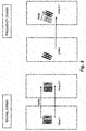
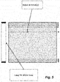
- Figure 5 and Figure 6 show how a full 2D implementation of Göertzel in effect would be a combination of many 1D Göertzel calculations.
- the calculations can be made sparser than the example in Figure 7 .
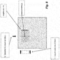
- One way is as shown in Figure 8 , where the input cells for the transformation into the frequency domain are only taken around the position of the index for which the value is needed. However, this would still require the rows to wait for the results of the columns, or vice versa.
- An advantage would be that the length of the amount of cells could become an input parameter, allowing for more differentiation between features, while it could also be possible to capture details of the object being classified.
- FIG. 9 A more effective calculation is shown in Figure 9 .
- the result of the index is taken by separately calculating the 1D output for the row and column at the index and then combining this into a single value.
- the biggest advantage in this manner is that it makes no difference if the 1D for the row or the 1D for the column is calculated first, so the value for the row and column can be calculated in parallel.
- An even great speed gain can be achieved by limiting the length of the input as shown in Figure 10 , where in this case only a single row and column input need to be calculated.
- Figure 11 shows how one could take the data using a freely chosen numbers of axis, which need not even be parallel with the row and columns, without changing the principles used in this method.
- Figures Figure 12A , Figure 12B and Figure 12C give examples of possible lookup tables that can be used as discrete digital filters.
- lookup tables can be created as digital filter input, meaning that the designer using the method described has a great number of options to train the algorithms.
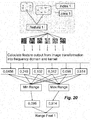
- FIG 13 an example is given of how much the described method can clean the data to give better input for a classifier.
- the left plot has been generated by converting an image to the frequency domain with this method, while the right plot is the same input image but converted with FFT. Note that for the sake of the example with the comparison the size of the input image has been chosen as a power of 2 (32*32). However when using the discrete digital filters of this method in practice there is no limitation in size such as for FFT.
- Figure 14A and Figure 14B show how this method also allows for better capturing of movements.
- Figure 14A a same type of comparison is shown as for Figure 13 .
- the combination of row and column indexes, discrete digital filter settings, sparse zones and other settings linked to this method, have been trained in such as way as to sparse react to head orientations.
- We see in the left plot of Figure 14A how not only the data has been cleaned up, but also that a specific peak is generated, with the magnitude and position of said peak being correlated to the head orientation.
- Figure 14B how the peak has shifted with the head orientation movement. In the image transformed with FFT there is so much noise, which continuously changes which the head orientation changes, that this same movement cannot be captured at all.
- Figure 14A and Figure 14B also show an example of sparse zones chosen to capture the head orientation movement.
- the optimizations will obviously choose the positions of these sparse zones close to the peak that correlates to head orientation, if head orientation is the characteristic to be captured in the frequency domain. It will be clear that in this example head orientation is only chosen for illustrative purposes, and that the same principles will be true for any object or movement to be captured.
- Kernels and offline training are part of any type of algorithms in object detection within images. The following descriptions of kernels and are therefore mainly in the context of how the values that follow from the frequency domain inputs are used.
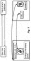
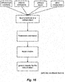
- Figure 15 shows the high-level flow diagram of object detection, in which the offline learning phase is indicated.
- Figure 16 shows the offline-learning block on a high level, how robust training and test sets need to be chosen that capture enough input images of the classifier that has to be learned using the underlying calculations of this method.
- Figure 17 shows this off-line learning phase is outlined, to find the best settings to train the method for a certain object.
- Figure 17 shows that the feature layouts can be optimised and we see also how kernels can be used on top of this frequency domain data. These can be Gabor-type kernels or wavelet-type kernel or any other kernel type. The principle is the same, with the frequency domain data that is extracted from the image being multiplied cell-by-cell in the frequency domain with the kernel. It will be clear that this gives many other tuning parameters for training the classifiers. There are also other classifier parameters that can be optimised, based on the type of classifier chosen to be trained with the frequency domain data.
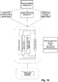
- Figure 18 shows the optimization loop of the offline-learning block on a high level.
- the images collected should be different from each other on the bases of for example:
- the images set of the defined object is split in training and test set. The first one, is used to train the detector, the second one to validate the current model.
- optimization described in Figure 32 can start. This is shown in Figure 17 and Figure 18 .
- a plurality of parameters in the optimization loop are now varied until, an acceptable result is found, i.e. a predetermined accuracy.
- These parameters can be related to the sparse zones, the features layout, the kernel settings and amount of kernels used, the classifier settings and the Gaussian filtering parameters.
- the Gaussian parameters will be described in more detail later.
- the optimization loop can seek a best result within multiple targets, among those the classification percentage (accuracy, recall, precision), and the achieved speed of calculations. Further, it is apparent that there are also higher order design options for the parameters. For example, the sparse zones can be set square or rectangular or even of a different shape; as for the kernels, the kernels parameters could be changed using filters described with a mathematical formula.
- the individual kernels values within the sparse zones can be directly varied although these values are the output of a mathematically defined filters.
- kernels whose result from this optimization are not predefined such as in methods similar to Gabor banks, will be different for each class.
- a classifier is built up from a plurality of features, with each feature possibly having different settings, different kernels, different sets of features within the defined sparse zones, different discrete digital filter settings and so forth.
- Kernel is meant to be any kind of filter in frequency domain, to be applied to the sparse zones as defined above.
- Such filter can be an edge detection linear filter, a Gabor filter (mixed Gaussian and Sinusoid), a Gaussian filter, an intensity enhancing filter, a lowpass filter, a Sobel edge detection filter, another edge operator like Canny, Canny-Deriche, Differential Sobel, Prewitt, Roberts, Cross, a corner detection operator like Harris operator, Shi and Tomasi, Level curve curvature, SUSAN, FAST, Wavelets and many others.
- a Gabor filter by way of example.
- That kernel in frequency domain involved the following parameters:
- the chosen kernel is a mathematical function, it can be calculated sparsely only in the indexes that have been chosen by the feature optimisations. This method also allows for multiple kernels to be used at the same time. Either for each feature or more than one kernel for a given feature.
- Figure 4 showed how only a sparse part of the frequency domain information is required to capture the sinusoidal information in the frequency domain.
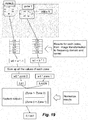
- Figure 19 shows how the values from each index in each feature, which follow from the discrete digital filters and kernel parameters, are combined.
- a feature is defined by 2 zones. Each zone is defined by a selection of indexes in the frequency domain. For each zone the sum is calculated of the values for each index that follow from the discrete digital filter settings and chosen kernel for that feature. This sum is then multiplied by a different weight for each zone, with this weight being negative for one of the zones and positive for the other zone.
- the value for a feature will be scaled, taking the sum of the two zones, and dividing the entire feature by that sum. With this calculation each feature will be normalized between -1 and 1.
- Figure 20 shows how these normalised outputs can be used in the training phase.
- Figure 19 showed that a single input image gives a single value. If one takes a plurality of images these will most likely each have a different output value. Used training and test set of images will then generate an output of values, within a range for the positives of [min, max] which will be within [-1,1] with the normalization, and also a range [min, max] for the negatives in the training and test sets.
- classifier can be used to train on these output values.
- Figure 21 shows how the [min, max] of the positives and negatives for a given trained feature will be discriminative.
- Positive and negative images used as inputs will both be normalized and overall fall in different ranges. This can be interpreted as a certain shape sparsely being captured in the frequency domain being more typical for positives than negatives. It will be clear that with a successful training phase these differences can be increased. It will also be clear that the more features are trained the more shapes are captured which define the positives and that the combination of these features can define the shape of the object to be classified.
Landscapes
- Engineering & Computer Science (AREA)
- Physics & Mathematics (AREA)
- General Physics & Mathematics (AREA)
- Theoretical Computer Science (AREA)
- Mathematical Physics (AREA)
- Data Mining & Analysis (AREA)
- Pure & Applied Mathematics (AREA)
- Mathematical Optimization (AREA)
- Mathematical Analysis (AREA)
- Computational Mathematics (AREA)
- General Engineering & Computer Science (AREA)
- Multimedia (AREA)
- Databases & Information Systems (AREA)
- Algebra (AREA)
- Software Systems (AREA)
- Computer Vision & Pattern Recognition (AREA)
- Operations Research (AREA)
- Computing Systems (AREA)
- Bioinformatics & Computational Biology (AREA)
- Life Sciences & Earth Sciences (AREA)
- Artificial Intelligence (AREA)
- Bioinformatics & Cheminformatics (AREA)
- Evolutionary Computation (AREA)
- Evolutionary Biology (AREA)
- Image Analysis (AREA)
- Threshing Machine Elements (AREA)
- Inspection Of Paper Currency And Valuable Securities (AREA)
- Complex Calculations (AREA)
Priority Applications (8)
| Application Number | Priority Date | Filing Date | Title |
|---|---|---|---|
| EP17156741.5A EP3364343A1 (de) | 2017-02-17 | 2017-02-17 | Verfahren zur bildverarbeitung für objektdetektion |
| PCT/EP2018/054032 WO2018150026A1 (en) | 2017-02-17 | 2018-02-19 | Method for image processing for content detection |
| KR1020197026847A KR102493075B1 (ko) | 2017-02-17 | 2018-02-19 | 콘텐츠 검출에 대한 이미지 프로세싱 방법 |
| JP2019544666A JP2020507864A (ja) | 2017-02-17 | 2018-02-19 | コンテンツ検出のための画像処理方法 |
| EP18705152.9A EP3583548A1 (de) | 2017-02-17 | 2018-02-19 | Verfahren zur bildverarbeitung zur inhaltsdetektion |
| US15/899,301 US10540537B2 (en) | 2017-02-17 | 2018-02-19 | Method for image processing for content detection with sparse zone salient features |
| IL268215A IL268215B (en) | 2017-02-17 | 2018-02-19 | Image processing method for content localization |
| CN201880012755.XA CN110392893A (zh) | 2017-02-17 | 2018-02-19 | 用于内容检测的图像处理方法 |
Applications Claiming Priority (1)
| Application Number | Priority Date | Filing Date | Title |
|---|---|---|---|
| EP17156741.5A EP3364343A1 (de) | 2017-02-17 | 2017-02-17 | Verfahren zur bildverarbeitung für objektdetektion |
Publications (1)
| Publication Number | Publication Date |
|---|---|
| EP3364343A1 true EP3364343A1 (de) | 2018-08-22 |
Family
ID=58094266
Family Applications (2)
| Application Number | Title | Priority Date | Filing Date |
|---|---|---|---|
| EP17156741.5A Withdrawn EP3364343A1 (de) | 2017-02-17 | 2017-02-17 | Verfahren zur bildverarbeitung für objektdetektion |
| EP18705152.9A Pending EP3583548A1 (de) | 2017-02-17 | 2018-02-19 | Verfahren zur bildverarbeitung zur inhaltsdetektion |
Family Applications After (1)
| Application Number | Title | Priority Date | Filing Date |
|---|---|---|---|
| EP18705152.9A Pending EP3583548A1 (de) | 2017-02-17 | 2018-02-19 | Verfahren zur bildverarbeitung zur inhaltsdetektion |
Country Status (7)
| Country | Link |
|---|---|
| US (1) | US10540537B2 (de) |
| EP (2) | EP3364343A1 (de) |
| JP (1) | JP2020507864A (de) |
| KR (1) | KR102493075B1 (de) |
| CN (1) | CN110392893A (de) |
| IL (1) | IL268215B (de) |
| WO (1) | WO2018150026A1 (de) |
Cited By (7)
| Publication number | Priority date | Publication date | Assignee | Title |
|---|---|---|---|---|
| CN109918538A (zh) * | 2019-01-25 | 2019-06-21 | 清华大学 | 视频信息处理方法及装置、存储介质及计算设备 |
| US10540537B2 (en) | 2017-02-17 | 2020-01-21 | Cogisen S.R.L. | Method for image processing for content detection with sparse zone salient features |
| US10586312B2 (en) | 2017-02-17 | 2020-03-10 | Cogisen S.R.L. | Method for image processing and video compression with sparse zone salient features |
| CN111507277A (zh) * | 2020-04-20 | 2020-08-07 | 国网安徽省电力有限公司 | 一种作业流程规范性识别模型的构建方法及应用 |
| WO2021045935A1 (en) * | 2019-09-04 | 2021-03-11 | Advanced Micro Devices, Inc. | Method and apparatus for predicting kernel tuning parameters |
| CN113569707A (zh) * | 2021-07-23 | 2021-10-29 | 北京百度网讯科技有限公司 | 活体检测方法、装置、电子设备以及存储介质 |
| CN117765264A (zh) * | 2024-02-22 | 2024-03-26 | 北京理工大学 | 基于频率自适应膨胀卷积的图像语义分割方法及系统 |
Families Citing this family (6)
| Publication number | Priority date | Publication date | Assignee | Title |
|---|---|---|---|---|
| US11301733B2 (en) | 2018-05-18 | 2022-04-12 | Google Llc | Learning data augmentation strategies for object detection |
| CN109522925B (zh) * | 2018-09-30 | 2021-08-06 | 咪咕文化科技有限公司 | 一种图像识别方法、装置和存储介质 |
| CN109977792B (zh) * | 2019-03-04 | 2021-11-05 | 上海商汤智能科技有限公司 | 人脸特征压缩方法及装置 |
| CN110083430B (zh) * | 2019-04-30 | 2022-03-29 | 成都映潮科技股份有限公司 | 一种系统主题色更换方法、装置及介质 |
| US11120273B2 (en) * | 2019-06-21 | 2021-09-14 | Gfycat, Inc. | Adaptive content classification of a video content item |
| CN112529080B (zh) * | 2020-12-11 | 2023-07-25 | 深圳龙岗智能视听研究院 | 一种基于频谱特征判别的图像生成方法 |
Citations (3)
| Publication number | Priority date | Publication date | Assignee | Title |
|---|---|---|---|---|
| US20090238466A1 (en) | 2008-03-24 | 2009-09-24 | Oren Golan | Method and system for edge detection |
| EP2790126A1 (de) * | 2013-04-08 | 2014-10-15 | Cogisen SRL | Verfahren zur Blickverfolgung |
| EP2790130A1 (de) * | 2013-04-08 | 2014-10-15 | Cogisen SRL | Verfahren zur Objekterkennung |
Family Cites Families (11)
| Publication number | Priority date | Publication date | Assignee | Title |
|---|---|---|---|---|
| JP3815689B2 (ja) * | 2003-11-20 | 2006-08-30 | 松下電器産業株式会社 | 移動物体検出装置及び移動物体検出方法 |
| JP4757808B2 (ja) * | 2007-01-25 | 2011-08-24 | 富士通テン株式会社 | 画像認識装置、画像認識方法、車両制御装置および車両制御方法 |
| KR101725126B1 (ko) * | 2011-12-14 | 2017-04-12 | 한국전자통신연구원 | 특징 벡터 분류기 및 이를 이용하는 인식 장치 |
| US8913835B2 (en) * | 2012-08-03 | 2014-12-16 | Kodak Alaris Inc. | Identifying key frames using group sparsity analysis |
| US20140198126A1 (en) * | 2013-01-16 | 2014-07-17 | Qualcomm Mems Technologies, Inc. | Methods and apparatus for reduced low-tone half-tone pattern visibility |
| US9195903B2 (en) * | 2014-04-29 | 2015-11-24 | International Business Machines Corporation | Extracting salient features from video using a neurosynaptic system |
| CN105096342A (zh) * | 2015-08-11 | 2015-11-25 | 杭州景联文科技有限公司 | 一种基于傅里叶描述子和方向梯度直方图的入侵检测算法 |
| CN105631469A (zh) * | 2015-12-18 | 2016-06-01 | 华南理工大学 | 一种多层稀疏编码特征的鸟类图像识别方法 |
| CN105631807B (zh) * | 2015-12-21 | 2018-11-16 | 西安电子科技大学 | 基于稀疏域选取的单帧图像超分辨重建方法 |
| EP3364342A1 (de) | 2017-02-17 | 2018-08-22 | Cogisen SRL | Verfahren zur bildverarbeitung und videokompression |
| EP3364343A1 (de) | 2017-02-17 | 2018-08-22 | Cogisen SRL | Verfahren zur bildverarbeitung für objektdetektion |
-
2017
- 2017-02-17 EP EP17156741.5A patent/EP3364343A1/de not_active Withdrawn
-
2018
- 2018-02-19 IL IL268215A patent/IL268215B/en unknown
- 2018-02-19 US US15/899,301 patent/US10540537B2/en active Active
- 2018-02-19 WO PCT/EP2018/054032 patent/WO2018150026A1/en unknown
- 2018-02-19 KR KR1020197026847A patent/KR102493075B1/ko active IP Right Grant
- 2018-02-19 CN CN201880012755.XA patent/CN110392893A/zh active Pending
- 2018-02-19 JP JP2019544666A patent/JP2020507864A/ja not_active Ceased
- 2018-02-19 EP EP18705152.9A patent/EP3583548A1/de active Pending
Patent Citations (3)
| Publication number | Priority date | Publication date | Assignee | Title |
|---|---|---|---|---|
| US20090238466A1 (en) | 2008-03-24 | 2009-09-24 | Oren Golan | Method and system for edge detection |
| EP2790126A1 (de) * | 2013-04-08 | 2014-10-15 | Cogisen SRL | Verfahren zur Blickverfolgung |
| EP2790130A1 (de) * | 2013-04-08 | 2014-10-15 | Cogisen SRL | Verfahren zur Objekterkennung |
Cited By (9)
| Publication number | Priority date | Publication date | Assignee | Title |
|---|---|---|---|---|
| US10540537B2 (en) | 2017-02-17 | 2020-01-21 | Cogisen S.R.L. | Method for image processing for content detection with sparse zone salient features |
| US10586312B2 (en) | 2017-02-17 | 2020-03-10 | Cogisen S.R.L. | Method for image processing and video compression with sparse zone salient features |
| CN109918538A (zh) * | 2019-01-25 | 2019-06-21 | 清华大学 | 视频信息处理方法及装置、存储介质及计算设备 |
| CN109918538B (zh) * | 2019-01-25 | 2021-04-16 | 清华大学 | 视频信息处理方法及装置、存储介质及计算设备 |
| WO2021045935A1 (en) * | 2019-09-04 | 2021-03-11 | Advanced Micro Devices, Inc. | Method and apparatus for predicting kernel tuning parameters |
| CN111507277A (zh) * | 2020-04-20 | 2020-08-07 | 国网安徽省电力有限公司 | 一种作业流程规范性识别模型的构建方法及应用 |
| CN111507277B (zh) * | 2020-04-20 | 2023-05-09 | 国网安徽省电力有限公司 | 一种作业流程规范性识别模型的构建方法及应用 |
| CN113569707A (zh) * | 2021-07-23 | 2021-10-29 | 北京百度网讯科技有限公司 | 活体检测方法、装置、电子设备以及存储介质 |
| CN117765264A (zh) * | 2024-02-22 | 2024-03-26 | 北京理工大学 | 基于频率自适应膨胀卷积的图像语义分割方法及系统 |
Also Published As
| Publication number | Publication date |
|---|---|
| US20180239952A1 (en) | 2018-08-23 |
| US10540537B2 (en) | 2020-01-21 |
| CN110392893A (zh) | 2019-10-29 |
| JP2020507864A (ja) | 2020-03-12 |
| WO2018150026A1 (en) | 2018-08-23 |
| IL268215B (en) | 2022-07-01 |
| IL268215A (en) | 2019-09-26 |
| KR20190121323A (ko) | 2019-10-25 |
| EP3583548A1 (de) | 2019-12-25 |
| KR102493075B1 (ko) | 2023-01-27 |
Similar Documents
| Publication | Publication Date | Title |
|---|---|---|
| EP3364343A1 (de) | Verfahren zur bildverarbeitung für objektdetektion | |
| Wei et al. | FPGA implementation of AdaBoost algorithm for detection of face biometrics | |
| Sahoo et al. | Hand gesture recognition using DWT and F‐ratio based feature descriptor | |
| Meethongjan et al. | An intelligent fused approach for face recognition | |
| CN102508547A (zh) | 基于计算机视觉的手势输入法构建方法及系统 | |
| Vishwakarma et al. | An efficient hybrid DWT-fuzzy filter in DCT domain based illumination normalization for face recognition | |
| Patil et al. | Expression invariant face recognition using local binary patterns and contourlet transform | |
| EP2790130A1 (de) | Verfahren zur Objekterkennung | |
| Mu et al. | Discrete stationary wavelet transform based saliency information fusion from frequency and spatial domain in low contrast images | |
| Runxin et al. | Survey on image saliency detection methods | |
| Ouanan et al. | Gabor-zernike features based face recognition scheme | |
| Owusu et al. | An SVM–AdaBoost-based face detection system | |
| Li et al. | Face recognition with Riesz binary pattern | |
| Omidyeganeh et al. | Application of 3D-wavelet statistics to video analysis | |
| Haijing et al. | Proposal of novel histogram features for face detection | |
| Rahman et al. | Face detection and sex identification from color images using adaboost with SVM based component classifier | |
| Fan et al. | Efficient Gabor phase based illumination invariant for face recognition | |
| Farouk et al. | Nonlinearity reduction of manifolds using Gaussian blur for handshape recognition based on multi-dimensional grids | |
| Li et al. | Coupling deep correlation filter and online discriminative learning for visual object tracking | |
| Chen et al. | Boosting local Gabor binary patterns for gender recognition | |
| Nimbalkar et al. | Face and hand gesture recognition using principle component analysis and kNN classifier | |
| Yuan et al. | Dual-encoded features from both spatial and Curvelet domains for image smoke recognition | |
| Bhowmik et al. | Quotient based multiresolution image fusion of thermal and visual images using daubechies wavelet transform for human face recognition | |
| Jiang et al. | Face recognition by combining wavelet transform and K-nearest neighbor | |
| Chen et al. | Noise Robust Illumination Invariant Face Recognition via Contourlet Transform in Logarithm Domain |
Legal Events
| Date | Code | Title | Description |
|---|---|---|---|
| PUAI | Public reference made under article 153(3) epc to a published international application that has entered the european phase |
Free format text: ORIGINAL CODE: 0009012 |
|
| AK | Designated contracting states |
Kind code of ref document: A1 Designated state(s): AL AT BE BG CH CY CZ DE DK EE ES FI FR GB GR HR HU IE IS IT LI LT LU LV MC MK MT NL NO PL PT RO RS SE SI SK SM TR |
|
| AX | Request for extension of the european patent |
Extension state: BA ME |
|
| STAA | Information on the status of an ep patent application or granted ep patent |
Free format text: STATUS: THE APPLICATION IS DEEMED TO BE WITHDRAWN |
|
| 18D | Application deemed to be withdrawn |
Effective date: 20190223 |