EP3364223A1 - Mounting of optical elements for imaging in air vehicles - Google Patents
Mounting of optical elements for imaging in air vehicles Download PDFInfo
- Publication number
- EP3364223A1 EP3364223A1 EP18156036.8A EP18156036A EP3364223A1 EP 3364223 A1 EP3364223 A1 EP 3364223A1 EP 18156036 A EP18156036 A EP 18156036A EP 3364223 A1 EP3364223 A1 EP 3364223A1
- Authority
- EP
- European Patent Office
- Prior art keywords
- mounting structure
- optical
- optical element
- optical elements
- undercuts
- Prior art date
- Legal status (The legal status is an assumption and is not a legal conclusion. Google has not performed a legal analysis and makes no representation as to the accuracy of the status listed.)
- Granted
Links
Images



Classifications
-
- G—PHYSICS
- G02—OPTICS
- G02B—OPTICAL ELEMENTS, SYSTEMS OR APPARATUS
- G02B7/00—Mountings, adjusting means, or light-tight connections, for optical elements
- G02B7/02—Mountings, adjusting means, or light-tight connections, for optical elements for lenses
- G02B7/022—Mountings, adjusting means, or light-tight connections, for optical elements for lenses lens and mount having complementary engagement means, e.g. screw/thread
-
- B—PERFORMING OPERATIONS; TRANSPORTING
- B64—AIRCRAFT; AVIATION; COSMONAUTICS
- B64U—UNMANNED AERIAL VEHICLES [UAV]; EQUIPMENT THEREFOR
- B64U20/00—Constructional aspects of UAVs
- B64U20/80—Arrangement of on-board electronics, e.g. avionics systems or wiring
- B64U20/87—Mounting of imaging devices, e.g. mounting of gimbals
-
- G—PHYSICS
- G02—OPTICS
- G02B—OPTICAL ELEMENTS, SYSTEMS OR APPARATUS
- G02B7/00—Mountings, adjusting means, or light-tight connections, for optical elements
- G02B7/02—Mountings, adjusting means, or light-tight connections, for optical elements for lenses
- G02B7/021—Mountings, adjusting means, or light-tight connections, for optical elements for lenses for more than one lens
-
- G—PHYSICS
- G02—OPTICS
- G02B—OPTICAL ELEMENTS, SYSTEMS OR APPARATUS
- G02B7/00—Mountings, adjusting means, or light-tight connections, for optical elements
- G02B7/02—Mountings, adjusting means, or light-tight connections, for optical elements for lenses
- G02B7/025—Mountings, adjusting means, or light-tight connections, for optical elements for lenses using glue
-
- H—ELECTRICITY
- H04—ELECTRIC COMMUNICATION TECHNIQUE
- H04N—PICTORIAL COMMUNICATION, e.g. TELEVISION
- H04N23/00—Cameras or camera modules comprising electronic image sensors; Control thereof
- H04N23/50—Constructional details
- H04N23/54—Mounting of pick-up tubes, electronic image sensors, deviation or focusing coils
-
- H—ELECTRICITY
- H04—ELECTRIC COMMUNICATION TECHNIQUE
- H04N—PICTORIAL COMMUNICATION, e.g. TELEVISION
- H04N7/00—Television systems
- H04N7/18—Closed-circuit television [CCTV] systems, i.e. systems in which the video signal is not broadcast
- H04N7/183—Closed-circuit television [CCTV] systems, i.e. systems in which the video signal is not broadcast for receiving images from a single remote source
-
- B—PERFORMING OPERATIONS; TRANSPORTING
- B64—AIRCRAFT; AVIATION; COSMONAUTICS
- B64U—UNMANNED AERIAL VEHICLES [UAV]; EQUIPMENT THEREFOR
- B64U2101/00—UAVs specially adapted for particular uses or applications
- B64U2101/30—UAVs specially adapted for particular uses or applications for imaging, photography or videography
Definitions
- the disclosed subject matter relates generally to imaging apparatus and methods, and more specifically to optical elements usable in air vehicles and munitions.
- Quality imaging optical components are made from crystalline and glass materials, which are very brittle and sensitive to stress concentrations and tensile stresses. Mounting of elements made from these materials for survival under high gravitational forces such as unmanned air vehicles, rockets, and gun launches can be very challenging due to catastrophic failure modes of these brittle materials. Any existing or new stress concentration can cause a fracture initiation point and the optical element can be prone to shattering. This can happen, for example, after long-term storage and transport, when the adhesive holding optical elements in place breaks down and regular vibrations cause contact between one or more optical elements and the housing holding them in place.
- the present disclosure is directed to an optical assembly comprising a mounting structure, a plurality of optical elements, and a conformal filler material.
- the mounting structure has a plurality of axially spaced circumferentially recessed undercuts formed into an inner surface of the mounting structure.
- the optical elements are axially spaced in the mounting structure.
- At least one of the optical elements includes an undercut in a perimeter edge surface.
- the undercut is aligned with one of the plurality of undercuts in the mounting structure, such that the aligned circumferential undercuts define a void.
- the conformal filler material is cast in place in the void to create a mechanical lock between the optical element and mounting structure.
- the present disclosure is directed to a method for making an optical assembly.
- a mounting structure is provided having a plurality of axially spaced circumferential recessed undercuts formed into an inner surface of the mounting structure.
- a first optical element is inserted into a bore of the mounting structure, the first optical element including an undercut in a perimeter edge surface of the optical element.
- the undercut is aligned in the perimeter edge of the optical element with one of the plurality of undercuts in the mounting structure, such that the aligned circumferential undercuts define a void.
- a conformal filler material is cast in place into the void to create a mechanical lock between the optical element and mounting structure.
- the present disclosure relates to an optical assembly and method of its assembly.
- This assembly includes a mounting structure that houses a plurality of axially spaced optical elements. Both the mounting structure and the optical elements have circumferential undercuts that are aligned when the optical elements are installed. These undercuts together define voids between each optical element and the mounting structure. Conformal filler material is cast in place into each void, thereby creating a resilient mechanical lock between each optical element and the mounting structure.
- FIG. 1 schematically depicts an air vehicle 10 in transit to a ground location 12.
- Air vehicle 10 can be an unmanned air vehicle (UAV), rocket, missile, or other munitions, though the disclosure is not so limited.
- UAV unmanned air vehicle
- Air vehicle 10 is outfitted with an imaging system (not visible) at or near nose 16.
- the imaging system provides still images and/or video of some or all of view range 18. These images or videos are taken by a full-range imaging sensor 20, which is in communication with on-board controller 22.
- On-board controller 22 can, for example, use and process data from imaging sensor 20 for guidance purposes, and/or can include a wireless radio configured to communicate with external location 24, e.g. to transmit images or video to external location 24.
- the imaging system can include an embodiment of an optical assembly according to the present disclosure.
- One such non-limiting embodiment is shown in FIG. 2 .
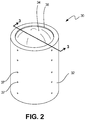
- FIGS. 2 , 3 , and 4 depict optical assembly 30, an ordered series of lenses used for optical conditioning of light received by imaging sensor 20 of air vehicle 10.
- FIG. 2 is a perspective view of optical assembly 30 (illustrating section plane 3-3)
- FIG. 3 is a sectional view of optical assembly 30 through section line 3-3
- FIG. 4 is an exploded perspective view of optical assembly 30.
- FIGS. 2 , 3 , and 4 illustrate optical assembly 30 with mounting structure 32 and a plurality of optical elements 34 axially spaced in inner bore 36.
- FIG. 3 and 4 depict additional details of mounting structure 32, optical elements 34, and bore 36, including ports 37, undercuts 38 in perimeter edge surface 40 of optical elements 34, and circumferential recessed undercuts 44 in inner surface 42 of mounting structure 32.
- mounting structure 32 is a substantially cylindrical structure that supports and retains several optical elements 34 at set axial positions within bore 36, a central axial passage extending through mounting structure 32.
- Inner surface 42 defines an inner surface of mounting structure 32 along bore 36.
- inner surface 42 is generally cylindrical except where interrupted by circumferential recessed undercuts 44.
- Circumferential recessed undercuts 44 are annular grooves or channels disposed at axial locations along inner surface 42 corresponding to assembly locations of optical element 34.
- inner surface 42 can have one or more circumferential recessed undercuts 44 for each optical element 34.
- Optical elements 34 are lenses, prisms, mirrors, or other elements of an optical assembly. Each optical element 34 has a perimeter edge surface 40 defining an outer perimeter of the optical element. Undercuts 38 are annular grooves or channels disposed circumferentially about at least some optical elements 34, within perimeter edge surfaces 40. In some embodiments, each optical element 34 has at least one undercut 38. In other embodiments, some optical elements 34 may not include undercuts.
- optical elements 34 are inserted into bore 36 of mounting structure 32 and aligned such that undercuts 38 face circumferential recessed undercuts 44. In this assembled state of optical assembly 30, alignment of each undercut 38 with a matching circumferential recessed undercut 44 in inner surface 42 defines voids 48.
- Voids 48 are annular passages formed by and between perimeter edge surfaces 40 and inner surface 42. Voids 48 are filled with conformal filler material 54 (not shown in FIGS. 2 , 3 , or 4 , but discussed below with respect to FIGS. 7 and 8). In the depicted embodiment, when each optical element 34 is situated at its installation location within mounting structure 32, the optical element is surrounded by a single void 48. Voids 48 are accessible via ports 37, which in this embodiment extend fully and radially through mounting structure 32 and provide communication between an outer surface of mounting structure 32 and at least one circumferential recessed undercut 44. Each void 48 can be accessible via multiple ports 37; in the depicted embodiment (see FIG.
- one or more ports 37 can be provided with a longitudinal component as well, either through mounting structure 32 and/or through one or more optical elements 34.
- conformal ports 37 are used to inject conformal filler 54 into voids 48 to resiliently secure optical elements 34 within mounting structure 32.
- conformal filler material 54, or a precursor thereof can include polymers (such as injection molded materials), elastomers, cements, or adhesives such as epoxies, urethane, and polysulfides. Additionally and/or alternatively it can also include potting materials, hot melt adhesives, plasters, or other suitable materials that can be cast or injected into the void then subsequently cured or hardened.
- conformal filler material 54, or a precursor thereof is selected from a group consisting of: epoxy, silicone, urethane resin, solder material, braze material, frit glass, ceramic cement, and combinations thereof.
- FIG. 4 illustrates a method for making optical assembly 30.
- a first of the plurality of optical elements 34 is inserted into bore 36 of mounting structure 32, and positioned at its installation location (as discussed above) so as to define void 48.
- This optical element 34 is then secured within bore 36 by injection of conformal filler material 54 into void 48 via port(s) 37. This process can be repeated to successively install all optical elements 34 into mounting structure 32.
- FIGS. 3 and 4 further illustrate spacers 56.
- Spacers 56 are situated between adjacent optical elements 34, and are sized to provide a desired relative axial spacing or positioning of each optical element 34.
- optical assembly 30 can be formed by stacking all optical elements 34 and spacers 56 within bore 36, then injecting conformal filler material 54 to lock optical elements 34 in place.
- FIGS. 5A and 5B respectively show convex optical element 50 and concave optical element 52, each with undercut 38.
- alternating ones of convex optical element 50 and concave optical element 52 are inserted into bore 36.
- optical elements 34 can be separated by spacers 56, which are assembled between adjacent optical elements 34.
- optical elements 34 can be spaced via steps or shelves of inner surface 42, as discussed below with respect to FIG. 7 .
- FIGS. 6 and 7 illustrate two embodiments of optical assembly 30, in a final (assembled) state.
- FIGS. 6 and 7 substantially parallel FIG. 3 (described above), but additionally illustrate conformal filler material 54 in place within voids 48.
- FIG. 6 illustrates an embodiment wherein optical elements 34 are positioned axially by means of spacers 56.
- Spacers 56 determine an axial offset between adjacent optical elements 34 so as to align undercuts 38 with circumferential recessed undercuts 44.
- mounting structure 32 includes a cylindrical body and a central bore defined by a cylindrical inner surface 40.
- spacers 56 can particularly be situated between adjacent convex optical elements 50 and concave optical elements 52.
- FIG. 7 illustrates an alternative embodiment that eschews spacers 56 (see FIG. 6 ) in favor of steps 158.
- optical elements 134 have decreasing diameter as a function of axial/longitudinal position, from top to bottom.
- inner surface 142 of bore 136 has steps 158 at axial locations selected to support optical elements 134 with undercuts 138 facing circumferential recessed undercuts 144. Accordingly, the width of bore 136 increases in a stepwise fashion along the optical/longitudinal axis of optical assembly 130, between its open end and a receiving end.
- optical elements 134 are placed into bore 136, and allowed to settle onto a step 158 of inner surface 142, such that the diameter of successive optical elements 134 increases in a matching stepwise fashion along the optical axis.
- Conformal filler material 154 locks optical elements 134 into place, once cured.
- voids 48/148 are filled with conformal filler material 54/154.
- Each undercut 38/138 in optical elements 34/134 is aligned with corresponding ones of the plurality of undercuts 44/144 in mounting structure 32/132, the aligned circumferential undercuts 38/138 and 44/144 defining axially spaced voids 48/148.
- Conformal filler material 54/154 can be cast in place in void(s) 48/148 to create a mechanical lock between each optical element 34/134 and inner surface 42/142 of mounting structure 32/132.
- This mechanical lock can be, for example, a compressive force independent of any adhesive properties that may or may not be provided by the selected filler material 54/154.
- many installations utilizing such a system may be stored for long periods of time, exposed to extreme environmental and thermal variation, as well as vibrations from transport. Over time, any adhesive properties which may be present at the time of manufacture are prone to breaking down but the mechanical lock can remain for a much longer time period, extending the life of the product.
- the conformal material selection for a gun hard application will be a mechanically stable structural material that also possesses properties to address CTE mismatches between the optical elements and the mounting structure.
- the filled void will create a mechanical lock between the optical element and mounting structure with high surface area in contact, so stress concentrations will be minimized with this configuration. This configuration will not need to rely on bond strength of the conformal material with either the optical element or the mounting structure.
- the undercut shapes in both components can also be "tuned" in size, location, and geometry to impart compressive stresses on the more vulnerable locations of the optical elements during high acceleration environments like a gun launch.
- Optical array 30 is formed by inserting optical elements 34 within mounting structure 32, then performing a casting step wherein conformal filler material 54 is injected into resulting voids 48 and cured or otherwise allowed to harden into rigid locking elements disposed between inner surface 42 of mounting structure 32 and perimeter edge surface 40 of optical elements 34.
- optical assembly 30/130 can include spacers 56 disposed between adjacent optical elements (see FIG. 6 ), or can have steps 158 along inner surface 142 (see FIG. 7 ).
- optical array 30 may include both steps and spacers to position optical elements 34.
- the aforementioned casting step comprises injecting a curable filler material into a plurality of ports, such as a radial port providing communication between an outer surface of the mounting structure and at least one of the circumferential recessed undercuts; and curing the filler material to form the mechanical lock.
- the mechanical lock can include a residual compressive force between the mounting structure and the optical element independent of any adhesive bond which may exist.
- the conformal filler material, or a precursor thereof is selected from a group consisting of: epoxy, silicone, urethane resin, solder material, braze material, frit glass, ceramic cement, and combinations thereof.
- optical assembly 30/130 includes a plurality of optical elements 34/134 locked into mounting assembly 32/132 by the injection and curing of conformal filler material 52/152 to form a durable structure capable of withstanding heavy acceleration loads with minimal crack initiation or other damage to sensitive imaging components.
- An optical assembly comprising: a mounting structure including a plurality of axially spaced circumferential recessed undercuts formed into an inner surface of the mounting structure; a plurality of optical elements axially spaced in the mounting structure, at least one of the plurality of optical elements including an undercut in a perimeter edge surface of the optical element, the undercut in the perimeter edge aligned with one of the plurality of undercuts in the mounting structure, the aligned circumferential undercuts defining a void; and a conformal filler material cast in place in the void to create a mechanical lock between the optical element and mounting structure.
- optical assembly of the preceding paragraph can optionally include, additionally and/or alternatively, any one or more of the following features, configurations and/or additional components:
- the mounting structure further comprises: a plurality of ports providing communication between an outer surface of the mounting structure and at least one of the circumferential recessed undercuts.
- a further embodiment of the foregoing optical assembly wherein the mounting structure includes a cylindrical body and a central bore defined by the inner surface.
- a further embodiment of the foregoing optical assembly wherein a width of the central bore increases stepwise along an optical axis between the open end and the receiving end.
- a further embodiment of the foregoing optical assembly wherein the conformal filler material, or a precursor thereof, is selected from a group consisting of: epoxy, silicone, urethane resin, solder material, braze material, frit glass, ceramic cement, and combinations thereof.
- a further embodiment of the foregoing optical assembly further comprising: a full-range image sensor disposed at a receiving end of the optical assembly.
- a further embodiment of the foregoing optical assembly wherein the image sensor is connected to a wireless communication system for transmitting a sensed image to an external location.
- a further embodiment of the foregoing optical assembly wherein the plurality of optical elements including alternating ones of a convex optical element and a concave optical element.
- a further embodiment of the foregoing optical assembly further comprising: a plurality of spacers disposed between adjacent ones of the convex optical element and the concave optical element.
- a method for making an optical assembly comprising: providing a mounting structure including a plurality of axially spaced circumferential recessed undercuts formed into an inner surface of the mounting structure; inserting a first optical element into a bore of the mounting structure, the first optical element including an undercut in a perimeter edge surface of the optical element; aligning the undercut in the perimeter edge of the optical element with one of the plurality of undercuts in the mounting structure, the aligned circumferential undercuts defining a void; and casting a conformal filler material in place into the void to create a mechanical lock between the optical element and mounting structure.
- the method of the preceding paragraph can optionally include, additionally and/or alternatively, any one or more of the following features, configurations and/or additional components:
- a further embodiment of the foregoing method further comprising: after the inserting step, inserting a plurality of axially spaced optical elements into the bore of the mounting structure, each of the plurality of axially spaced optical elements having an undercut in a perimeter edge surface.
- a further embodiment of the foregoing method further comprising: aligning the undercut in the perimeter edge of each of the plurality of optical elements with corresponding ones of the plurality of recessed undercuts in the inner surface of the mounting structure to define a plurality of axially spaced voids; casting a conformal filler material in place in each of the plurality of voids to create a mechanical lock between the optical element and mounting structure.
- a further embodiment of the foregoing method further comprising: assembling a plurality of spacers between adjacent ones of the plurality of optical elements.
- the casting step comprises: injecting a curable filler material into a plurality of ports providing communication between an outer surface of the mounting structure and at least one of the circumferential recessed undercuts; and curing the filler material to form the mechanical lock; wherein the mechanical lock is a residual compressive force between the mounting structure and the optical element independent of any adhesive bond which may exist.
- conformal filler material is selected from a group consisting of: epoxy, silicone, urethane resin, solder material, braze material, frit glass, ceramic cement, and combinations thereof.
- a further embodiment of the foregoing method further comprising: installing a full-range image sensor at a receiving end of the optical assembly.
Landscapes
- Physics & Mathematics (AREA)
- Engineering & Computer Science (AREA)
- General Physics & Mathematics (AREA)
- Optics & Photonics (AREA)
- Multimedia (AREA)
- Signal Processing (AREA)
- Aviation & Aerospace Engineering (AREA)
- Microelectronics & Electronic Packaging (AREA)
- Mechanical Engineering (AREA)
- Remote Sensing (AREA)
- Lens Barrels (AREA)
- Mounting And Adjusting Of Optical Elements (AREA)
Abstract
Description
- The disclosed subject matter relates generally to imaging apparatus and methods, and more specifically to optical elements usable in air vehicles and munitions.
- Quality imaging optical components are made from crystalline and glass materials, which are very brittle and sensitive to stress concentrations and tensile stresses. Mounting of elements made from these materials for survival under high gravitational forces such as unmanned air vehicles, rockets, and gun launches can be very challenging due to catastrophic failure modes of these brittle materials. Any existing or new stress concentration can cause a fracture initiation point and the optical element can be prone to shattering. This can happen, for example, after long-term storage and transport, when the adhesive holding optical elements in place breaks down and regular vibrations cause contact between one or more optical elements and the housing holding them in place.
- In one embodiment, the present disclosure is directed to an optical assembly comprising a mounting structure, a plurality of optical elements, and a conformal filler material. The mounting structure has a plurality of axially spaced circumferentially recessed undercuts formed into an inner surface of the mounting structure. The optical elements are axially spaced in the mounting structure. At least one of the optical elements includes an undercut in a perimeter edge surface. The undercut is aligned with one of the plurality of undercuts in the mounting structure, such that the aligned circumferential undercuts define a void. The conformal filler material is cast in place in the void to create a mechanical lock between the optical element and mounting structure.
- In another embodiment, the present disclosure is directed to a method for making an optical assembly. A mounting structure is provided having a plurality of axially spaced circumferential recessed undercuts formed into an inner surface of the mounting structure. A first optical element is inserted into a bore of the mounting structure, the first optical element including an undercut in a perimeter edge surface of the optical element. The undercut is aligned in the perimeter edge of the optical element with one of the plurality of undercuts in the mounting structure, such that the aligned circumferential undercuts define a void. A conformal filler material is cast in place into the void to create a mechanical lock between the optical element and mounting structure.
-
-
FIG. 1 shows an aerial vehicle in flight with an imaging system disposed at a forward end thereof. -
FIG. 2 is a perspective view of an optical assembly for the imaging system. -
FIG. 3 is a sectional view of the optical assembly ofFIG. 2 . -
FIG. 4 shows an exploded view of the optical assembly ofFIG. 2 . -
FIG. 5A is a side view of a first example optical element. -
FIG. 5B is a perspective view of a second example optical element. -
FIG. 6 is a sectional view of the assembly ofFIG. 2 , with conformal fills. -
FIG. 7 is a sectional view of an alternative embodiment of the assembly ofFIG. 7 . - The present disclosure relates to an optical assembly and method of its assembly. This assembly includes a mounting structure that houses a plurality of axially spaced optical elements. Both the mounting structure and the optical elements have circumferential undercuts that are aligned when the optical elements are installed. These undercuts together define voids between each optical element and the mounting structure. Conformal filler material is cast in place into each void, thereby creating a resilient mechanical lock between each optical element and the mounting structure.
-
FIG. 1 schematically depicts anair vehicle 10 in transit to aground location 12.Air vehicle 10 can be an unmanned air vehicle (UAV), rocket, missile, or other munitions, though the disclosure is not so limited. -
Air vehicle 10 is outfitted with an imaging system (not visible) at or nearnose 16. The imaging system provides still images and/or video of some or all ofview range 18. These images or videos are taken by a full-range imaging sensor 20, which is in communication with on-board controller 22. On-board controller 22 can, for example, use and process data fromimaging sensor 20 for guidance purposes, and/or can include a wireless radio configured to communicate withexternal location 24, e.g. to transmit images or video toexternal location 24. - To provide the desired or optimal resolution for
imaging sensor 20, the imaging system can include an embodiment of an optical assembly according to the present disclosure. One such non-limiting embodiment is shown inFIG. 2 . -
FIGS. 2 ,3 , and4 depictoptical assembly 30, an ordered series of lenses used for optical conditioning of light received byimaging sensor 20 ofair vehicle 10.FIG. 2 is a perspective view of optical assembly 30 (illustrating section plane 3-3),FIG. 3 is a sectional view ofoptical assembly 30 through section line 3-3, andFIG. 4 is an exploded perspective view ofoptical assembly 30.FIGS. 2 ,3 , and4 illustrateoptical assembly 30 withmounting structure 32 and a plurality ofoptical elements 34 axially spaced ininner bore 36.FIG. 3 and4 depict additional details ofmounting structure 32,optical elements 34, and bore 36, includingports 37, undercuts 38 inperimeter edge surface 40 ofoptical elements 34, and circumferentialrecessed undercuts 44 ininner surface 42 ofmounting structure 32. - In the illustrated embodiment,
mounting structure 32 is a substantially cylindrical structure that supports and retains severaloptical elements 34 at set axial positions withinbore 36, a central axial passage extending throughmounting structure 32.Inner surface 42 defines an inner surface ofmounting structure 32 alongbore 36. In the illustrated embodiment,inner surface 42 is generally cylindrical except where interrupted by circumferentialrecessed undercuts 44. Circumferentialrecessed undercuts 44 are annular grooves or channels disposed at axial locations alonginner surface 42 corresponding to assembly locations ofoptical element 34. In at least some embodiments,inner surface 42 can have one or more circumferentialrecessed undercuts 44 for eachoptical element 34. -
Optical elements 34 are lenses, prisms, mirrors, or other elements of an optical assembly. Eachoptical element 34 has aperimeter edge surface 40 defining an outer perimeter of the optical element.Undercuts 38 are annular grooves or channels disposed circumferentially about at least someoptical elements 34, withinperimeter edge surfaces 40. In some embodiments, eachoptical element 34 has at least one undercut 38. In other embodiments, someoptical elements 34 may not include undercuts. During assembly ofoptical array 30,optical elements 34 are inserted intobore 36 ofmounting structure 32 and aligned such that undercuts 38 face circumferentialrecessed undercuts 44. In this assembled state ofoptical assembly 30, alignment of eachundercut 38 with a matching circumferential recessed undercut 44 ininner surface 42 definesvoids 48. -
Voids 48 are annular passages formed by and betweenperimeter edge surfaces 40 andinner surface 42.Voids 48 are filled with conformal filler material 54 (not shown inFIGS. 2 ,3 , or4 , but discussed below with respect toFIGS. 7 and 8). In the depicted embodiment, when eachoptical element 34 is situated at its installation location withinmounting structure 32, the optical element is surrounded by asingle void 48.Voids 48 are accessible viaports 37, which in this embodiment extend fully and radially throughmounting structure 32 and provide communication between an outer surface ofmounting structure 32 and at least one circumferential recessed undercut 44. Eachvoid 48 can be accessible viamultiple ports 37; in the depicted embodiment (seeFIG. 4 ), fourradial ports 37 feed eachvoid 48, though the ports could be of any suitable shape or direction. In certain embodiments, one ormore ports 37 can be provided with a longitudinal component as well, either throughmounting structure 32 and/or through one or moreoptical elements 34. - In the example, non-limiting embodiment shown,
radial ports 37 are used to injectconformal filler 54 intovoids 48 to resiliently secureoptical elements 34 within mountingstructure 32. Generally, depending on the exact application and required properties,conformal filler material 54, or a precursor thereof, can include polymers (such as injection molded materials), elastomers, cements, or adhesives such as epoxies, urethane, and polysulfides. Additionally and/or alternatively it can also include potting materials, hot melt adhesives, plasters, or other suitable materials that can be cast or injected into the void then subsequently cured or hardened. In certain embodiments,conformal filler material 54, or a precursor thereof, is selected from a group consisting of: epoxy, silicone, urethane resin, solder material, braze material, frit glass, ceramic cement, and combinations thereof. - The exploded view of
FIG. 4 illustrates a method for makingoptical assembly 30. A first of the plurality ofoptical elements 34 is inserted intobore 36 of mountingstructure 32, and positioned at its installation location (as discussed above) so as to definevoid 48. Thisoptical element 34 is then secured withinbore 36 by injection ofconformal filler material 54 intovoid 48 via port(s) 37. This process can be repeated to successively install alloptical elements 34 into mountingstructure 32. -
FIGS. 3 and4 further illustratespacers 56.Spacers 56 are situated between adjacentoptical elements 34, and are sized to provide a desired relative axial spacing or positioning of eachoptical element 34. In some embodiments,optical assembly 30 can be formed by stacking alloptical elements 34 andspacers 56 withinbore 36, then injectingconformal filler material 54 to lockoptical elements 34 in place. -
FIGS. 5A and 5B respectively show convexoptical element 50 and concaveoptical element 52, each with undercut 38. In the non-limiting example embodiment shown inFIG. 4 , alternating ones of convexoptical element 50 and concaveoptical element 52 are inserted intobore 36. As discussed above,optical elements 34 can be separated byspacers 56, which are assembled between adjacentoptical elements 34. In other embodiments,optical elements 34 can be spaced via steps or shelves ofinner surface 42, as discussed below with respect toFIG. 7 . -
FIGS. 6 and 7 illustrate two embodiments ofoptical assembly 30, in a final (assembled) state.FIGS. 6 and 7 substantially parallelFIG. 3 (described above), but additionally illustrateconformal filler material 54 in place within voids 48. -
FIG. 6 illustrates an embodiment whereinoptical elements 34 are positioned axially by means ofspacers 56.Spacers 56, as discussed above, determine an axial offset between adjacentoptical elements 34 so as to alignundercuts 38 with circumferential recessed undercuts 44. In the embodiment ofFIG. 6 , mountingstructure 32 includes a cylindrical body and a central bore defined by a cylindricalinner surface 40. In some embodiments,spacers 56 can particularly be situated between adjacent convexoptical elements 50 and concaveoptical elements 52. -
FIG. 7 illustrates an alternative embodiment that eschews spacers 56 (seeFIG. 6 ) in favor ofsteps 158. As illustrated inFIG. 7 ,optical elements 134 have decreasing diameter as a function of axial/longitudinal position, from top to bottom. In this embodiment ofoptical assembly 130,inner surface 142 of bore 136 hassteps 158 at axial locations selected to supportoptical elements 134 withundercuts 138 facing circumferential recessed undercuts 144. Accordingly, the width of bore 136 increases in a stepwise fashion along the optical/longitudinal axis ofoptical assembly 130, between its open end and a receiving end. During assembly, successively larger-diameteroptical elements 134 are placed into bore 136, and allowed to settle onto astep 158 ofinner surface 142, such that the diameter of successiveoptical elements 134 increases in a matching stepwise fashion along the optical axis.Conformal filler material 154 locksoptical elements 134 into place, once cured. - As shown in both
FIG. 6 and FIG. 7 , voids 48/148 (and in some embodiments at least a portion ofports 37/137) are filled withconformal filler material 54/154. Each undercut 38/138 inoptical elements 34/134 is aligned with corresponding ones of the plurality ofundercuts 44/144 in mountingstructure 32/132, the aligned circumferential undercuts 38/138 and 44/144 defining axially spacedvoids 48/148.Conformal filler material 54/154 can be cast in place in void(s) 48/148 to create a mechanical lock between eachoptical element 34/134 andinner surface 42/142 of mountingstructure 32/132. This mechanical lock can be, for example, a compressive force independent of any adhesive properties that may or may not be provided by the selectedfiller material 54/154. For example, many installations utilizing such a system may be stored for long periods of time, exposed to extreme environmental and thermal variation, as well as vibrations from transport. Over time, any adhesive properties which may be present at the time of manufacture are prone to breaking down but the mechanical lock can remain for a much longer time period, extending the life of the product. - The conformal material selection for a gun hard application will be a mechanically stable structural material that also possesses properties to address CTE mismatches between the optical elements and the mounting structure. The filled void will create a mechanical lock between the optical element and mounting structure with high surface area in contact, so stress concentrations will be minimized with this configuration. This configuration will not need to rely on bond strength of the conformal material with either the optical element or the mounting structure. The undercut shapes in both components can also be "tuned" in size, location, and geometry to impart compressive stresses on the more vulnerable locations of the optical elements during high acceleration environments like a gun launch.
-
Optical array 30 is formed by insertingoptical elements 34 within mountingstructure 32, then performing a casting step whereinconformal filler material 54 is injected into resultingvoids 48 and cured or otherwise allowed to harden into rigid locking elements disposed betweeninner surface 42 of mountingstructure 32 andperimeter edge surface 40 ofoptical elements 34. To positionoptical elements 34/134 at appropriate axial locations within bore 36/136,optical assembly 30/130 can includespacers 56 disposed between adjacent optical elements (seeFIG. 6 ), or can havesteps 158 along inner surface 142 (seeFIG. 7 ). In some embodiments,optical array 30 may include both steps and spacers to positionoptical elements 34. - The aforementioned casting step comprises injecting a curable filler material into a plurality of ports, such as a radial port providing communication between an outer surface of the mounting structure and at least one of the circumferential recessed undercuts; and curing the filler material to form the mechanical lock. The mechanical lock can include a residual compressive force between the mounting structure and the optical element independent of any adhesive bond which may exist. As noted above, the conformal filler material, or a precursor thereof, is selected from a group consisting of: epoxy, silicone, urethane resin, solder material, braze material, frit glass, ceramic cement, and combinations thereof.
- As disclosed herein,
optical assembly 30/130 includes a plurality ofoptical elements 34/134 locked into mountingassembly 32/132 by the injection and curing ofconformal filler material 52/152 to form a durable structure capable of withstanding heavy acceleration loads with minimal crack initiation or other damage to sensitive imaging components. - The following are non-exclusive descriptions of possible embodiments of the present invention.
- An optical assembly comprising: a mounting structure including a plurality of axially spaced circumferential recessed undercuts formed into an inner surface of the mounting structure; a plurality of optical elements axially spaced in the mounting structure, at least one of the plurality of optical elements including an undercut in a perimeter edge surface of the optical element, the undercut in the perimeter edge aligned with one of the plurality of undercuts in the mounting structure, the aligned circumferential undercuts defining a void; and a conformal filler material cast in place in the void to create a mechanical lock between the optical element and mounting structure.
- The optical assembly of the preceding paragraph can optionally include, additionally and/or alternatively, any one or more of the following features, configurations and/or additional components:
- A further embodiment of the foregoing optical assembly, wherein the mounting structure further comprises: a plurality of ports providing communication between an outer surface of the mounting structure and at least one of the circumferential recessed undercuts.
- A further embodiment of the foregoing optical assembly, wherein the mounting structure includes a cylindrical body and a central bore defined by the inner surface.
- A further embodiment of the foregoing optical assembly, wherein a width of the central bore increases stepwise along an optical axis between the open end and the receiving end.
- A further embodiment of the foregoing optical assembly, wherein corresponding ones of the plurality of optical elements have a diameter increasing stepwise along the optical axis.
- A further embodiment of the foregoing optical assembly, wherein the conformal filler material, or a precursor thereof, is selected from a group consisting of: epoxy, silicone, urethane resin, solder material, braze material, frit glass, ceramic cement, and combinations thereof.
- A further embodiment of the foregoing optical assembly, further comprising: a full-range image sensor disposed at a receiving end of the optical assembly.
- A further embodiment of the foregoing optical assembly, wherein the image sensor is connected to a wireless communication system for transmitting a sensed image to an external location.
- A further embodiment of the foregoing optical assembly, wherein the plurality of optical elements including alternating ones of a convex optical element and a concave optical element.
- A further embodiment of the foregoing optical assembly, further comprising: a plurality of spacers disposed between adjacent ones of the convex optical element and the concave optical element.
- A method for making an optical assembly, the method comprising: providing a mounting structure including a plurality of axially spaced circumferential recessed undercuts formed into an inner surface of the mounting structure; inserting a first optical element into a bore of the mounting structure, the first optical element including an undercut in a perimeter edge surface of the optical element; aligning the undercut in the perimeter edge of the optical element with one of the plurality of undercuts in the mounting structure, the aligned circumferential undercuts defining a void; and casting a conformal filler material in place into the void to create a mechanical lock between the optical element and mounting structure.
- The method of the preceding paragraph can optionally include, additionally and/or alternatively, any one or more of the following features, configurations and/or additional components:
- A further embodiment of the foregoing method, further comprising: after the inserting step, inserting a plurality of axially spaced optical elements into the bore of the mounting structure, each of the plurality of axially spaced optical elements having an undercut in a perimeter edge surface.
- A further embodiment of the foregoing method, further comprising: aligning the undercut in the perimeter edge of each of the plurality of optical elements with corresponding ones of the plurality of recessed undercuts in the inner surface of the mounting structure to define a plurality of axially spaced voids; casting a conformal filler material in place in each of the plurality of voids to create a mechanical lock between the optical element and mounting structure.
- A further embodiment of the foregoing method, wherein the plurality of optical elements including alternating ones of a convex optical element and a concave optical element.
- A further embodiment of the foregoing method, further comprising: assembling a plurality of spacers between adjacent ones of the plurality of optical elements.
- A further embodiment of the foregoing method, wherein a width of the central bore increases stepwise along an optical axis between the open end and the receiving end.
- A further embodiment of the foregoing method, wherein corresponding ones of the plurality of optical elements have a diameter increasing stepwise along the optical axis.
- A further embodiment of the foregoing method, wherein the casting step comprises: injecting a curable filler material into a plurality of ports providing communication between an outer surface of the mounting structure and at least one of the circumferential recessed undercuts; and curing the filler material to form the mechanical lock; wherein the mechanical lock is a residual compressive force between the mounting structure and the optical element independent of any adhesive bond which may exist.
- A further embodiment of the foregoing method, wherein the conformal filler material, or a precursor thereof, is selected from a group consisting of: epoxy, silicone, urethane resin, solder material, braze material, frit glass, ceramic cement, and combinations thereof.
- A further embodiment of the foregoing method, further comprising: installing a full-range image sensor at a receiving end of the optical assembly.
- While the invention has been described with reference to an exemplary embodiment(s), it will be understood by those skilled in the art that various changes may be made and equivalents may be substituted for elements thereof without departing from the scope of the invention. In addition, many modifications may be made to adapt a particular situation or material to the teachings of the invention without departing from the essential scope thereof. Therefore, it is intended that the invention not be limited to the particular embodiment(s) disclosed, but that the invention will include all embodiments falling within the scope of the appended claims.
Claims (15)
- An optical assembly comprising:a mounting structure including a plurality of axially spaced circumferential recessed undercuts formed into an inner surface of the mounting structure;a plurality of optical elements axially spaced in the mounting structure, at least one of the plurality of optical elements including an undercut in a perimeter edge surface of the optical element, the undercut in the perimeter edge aligned with one of the plurality of undercuts in the mounting structure, the aligned circumferential undercuts defining a void; anda conformal filler material cast in place in the void to create a mechanical lock between the optical element and mounting structure.
- The optical assembly of claim 1, wherein the mounting structure further comprises:a plurality of ports providing communication between an outer surface of the mounting structure and at least one of the circumferential recessed undercuts.
- The optical assembly of claim 1 or 2, wherein the mounting structure includes a cylindrical body and a central bore defined by the inner surface.
- The optical assembly of claim 1, 2 or 3, wherein a width of the central bore increases stepwise along an optical axis between the open end and the receiving end,
wherein, optionally, corresponding ones of the plurality of optical elements have a diameter increasing stepwise along the optical axis. - The optical assembly of any preceding claim, wherein the conformal filler material, or a precursor thereof, is selected from a group consisting of: epoxy, silicone, urethane resin, solder material, braze material, frit glass, ceramic cement, and combinations thereof.
- The optical assembly of any preceding claim, further comprising:a full-range image sensor disposed at a receiving end of the optical assembly,
wherein, optionally, the image sensor is connected to a wireless communication system for transmitting a sensed image to an external location. - The optical assembly of any preceding claim, wherein the plurality of optical elements include alternating ones of a convex optical element and a concave optical element, the optical assembly optionally further comprising:a plurality of spacers disposed between adjacent ones of the convex optical element and the concave optical element.
- A method for making an optical assembly, the method comprising:providing a mounting structure including a plurality of axially spaced circumferential recessed undercuts formed into an inner surface of the mounting structure;inserting a first optical element into a bore of the mounting structure, the first optical element including an undercut in a perimeter edge surface of the optical element;aligning the undercut in the perimeter edge of the optical element with one of the plurality of undercuts in the mounting structure, the aligned circumferential undercuts defining a void; andcasting a conformal filler material in place into the void to create a mechanical lock between the optical element and mounting structure.
- The method of claim 8, further comprising:after the inserting step, inserting a plurality of axially spaced optical elements into the bore of the mounting structure, each of the plurality of axially spaced optical elements having an undercut in a perimeter edge surface.
- The method of claim 9, further comprising:aligning the undercut in the perimeter edge of each of the plurality of optical elements with corresponding ones of the plurality of recessed undercuts in the inner surface of the mounting structure to define a plurality of axially spaced voids; andcasting a conformal filler material in place in each of the plurality of voids to create a mechanical lock between the optical element and mounting structure.
- The method of claim 10, wherein the plurality of optical elements include alternating ones of a convex optical element and a concave optical element.
- The method of claim 10 or 11, further comprising:assembling a plurality of spacers between adjacent ones of the plurality of optical elements.
- The method of any of claims 8 to 12, wherein a width of the central bore increases stepwise along an optical axis between the open end and the receiving end, wherein, optionally, corresponding ones of the plurality of optical elements have a diameter increasing stepwise along the optical axis.
- The method of any of claims 8 to 13, wherein the casting step comprises:injecting a curable filler material into a plurality of ports providing communication between an outer surface of the mounting structure and at least one of the circumferential recessed undercuts; andcuring the filler material to form the mechanical lock;wherein the mechanical lock is a residual compressive force between the mounting structure and the optical element independent of any adhesive bond which may exist,wherein, optionally, the conformal filler material, or a precursor thereof, is selected from a group consisting of: epoxy, silicone, urethane resin, solder material, braze material, frit glass, ceramic cement, and combinations thereof.
- The method of any of claims 8 to 14, further comprising:installing a full-range image sensor at a receiving end of the optical assembly.
Applications Claiming Priority (1)
| Application Number | Priority Date | Filing Date | Title |
|---|---|---|---|
| US15/437,321 US10330884B2 (en) | 2017-02-20 | 2017-02-20 | Mounting of optical elements for imaging in air vehicles |
Publications (2)
| Publication Number | Publication Date |
|---|---|
| EP3364223A1 true EP3364223A1 (en) | 2018-08-22 |
| EP3364223B1 EP3364223B1 (en) | 2025-04-09 |
Family
ID=61226379
Family Applications (1)
| Application Number | Title | Priority Date | Filing Date |
|---|---|---|---|
| EP18156036.8A Active EP3364223B1 (en) | 2017-02-20 | 2018-02-09 | Mounting of optical elements for imaging in air vehicles |
Country Status (2)
| Country | Link |
|---|---|
| US (2) | US10330884B2 (en) |
| EP (1) | EP3364223B1 (en) |
Families Citing this family (3)
| Publication number | Priority date | Publication date | Assignee | Title |
|---|---|---|---|---|
| US10330884B2 (en) * | 2017-02-20 | 2019-06-25 | Rosemount Aerospace Inc. | Mounting of optical elements for imaging in air vehicles |
| TWI691782B (en) * | 2019-01-21 | 2020-04-21 | 大立光電股份有限公司 | Plastic lens barrel, imaging lens module and electronic device |
| US20230273391A1 (en) * | 2020-07-14 | 2023-08-31 | Nlight, Inc. | Opto-mechanical mounting for optical components |
Citations (7)
| Publication number | Priority date | Publication date | Assignee | Title |
|---|---|---|---|---|
| US4018405A (en) * | 1974-10-18 | 1977-04-19 | Northrop Corporation | Vehicle guidance control link utilizing light beam |
| GB1485619A (en) * | 1974-12-11 | 1977-09-14 | Emi Ltd | Missile guidance systems |
| US6122114A (en) * | 1996-11-26 | 2000-09-19 | Canon Kabushiki Kaisha | Optical-element supporting device and optical apparatus |
| JP2002251769A (en) * | 2001-02-26 | 2002-09-06 | Asahi Optical Co Ltd | Optical recording lens assembly and method of manufacturing the same |
| US20080100932A1 (en) * | 2004-11-08 | 2008-05-01 | Toshinari Noda | Lens Unit |
| WO2009000591A1 (en) * | 2007-06-26 | 2008-12-31 | Robert Bosch Gmbh | Camera objective, in particular for use in a motor vehicle, and method for its production |
| US20150273898A1 (en) * | 2014-03-27 | 2015-10-01 | Seiko Epson Corporation | Imaging unit, manufacturing method thereof, and liquid ejecting apparatus |
Family Cites Families (17)
| Publication number | Priority date | Publication date | Assignee | Title |
|---|---|---|---|---|
| US7926213B1 (en) * | 2007-04-13 | 2011-04-19 | Daktronics, Inc. | Electronic sign having slotted frame cabinets |
| CN100468114C (en) | 2005-12-16 | 2009-03-11 | 鸿富锦精密工业(深圳)有限公司 | Lens anti-shake structure and digital camera lens using it |
| CN102043219B (en) | 2009-10-23 | 2013-02-13 | 鸿富锦精密工业(深圳)有限公司 | Clamped lens group and lens module with same |
| KR101457418B1 (en) * | 2009-10-23 | 2014-11-04 | 삼성전자주식회사 | Method and apparatus for video coding according to the size of a hierarchical coding unit, video decoding method and apparatus thereof |
| FR2958013B1 (en) * | 2010-03-26 | 2014-06-20 | Snecma | TURBOMACHINE COMBUSTION CHAMBER WITH CENTRIFUGAL COMPRESSOR WITHOUT DEFLECTOR |
| KR101123497B1 (en) * | 2010-06-14 | 2012-03-23 | 윤동한 | Buried-Type Photonic Device Package Module Using a Thermocouple |
| JP5447231B2 (en) * | 2010-06-30 | 2014-03-19 | 株式会社富士通ゼネラル | Air conditioner refrigerant branching unit |
| JP5573425B2 (en) * | 2010-06-30 | 2014-08-20 | リコーイメージング株式会社 | Screw mount lens barrel |
| US9713194B2 (en) * | 2011-12-28 | 2017-07-18 | United States Cellular Corporation | System and method for data network reassignment |
| CN103312616A (en) * | 2012-03-16 | 2013-09-18 | 华为技术有限公司 | Method and device for establishing multicast path |
| MX354959B (en) * | 2012-06-30 | 2018-03-27 | Solarreserve Tech Llc | Light source sensing and pointing position-encoded optical proxy. |
| WO2014122849A1 (en) | 2013-02-05 | 2014-08-14 | シャープ株式会社 | Camera module |
| EP2833183A3 (en) * | 2013-07-31 | 2015-04-29 | JDS Uniphase Corporation | Flexible hermetic package for optical device |
| US9479686B2 (en) * | 2014-02-19 | 2016-10-25 | Melvyn H Kreitzer | Zoom lens optical system |
| JP6462386B2 (en) | 2015-02-05 | 2019-01-30 | 任天堂株式会社 | Program, communication terminal and display method |
| US10165256B2 (en) * | 2016-09-14 | 2018-12-25 | Amazon Technologies, Inc. | Aerial vehicle optical sensor configuration |
| US10330884B2 (en) * | 2017-02-20 | 2019-06-25 | Rosemount Aerospace Inc. | Mounting of optical elements for imaging in air vehicles |
-
2017
- 2017-02-20 US US15/437,321 patent/US10330884B2/en active Active
-
2018
- 2018-02-09 EP EP18156036.8A patent/EP3364223B1/en active Active
-
2019
- 2019-05-14 US US16/411,718 patent/US10656369B2/en active Active
Patent Citations (7)
| Publication number | Priority date | Publication date | Assignee | Title |
|---|---|---|---|---|
| US4018405A (en) * | 1974-10-18 | 1977-04-19 | Northrop Corporation | Vehicle guidance control link utilizing light beam |
| GB1485619A (en) * | 1974-12-11 | 1977-09-14 | Emi Ltd | Missile guidance systems |
| US6122114A (en) * | 1996-11-26 | 2000-09-19 | Canon Kabushiki Kaisha | Optical-element supporting device and optical apparatus |
| JP2002251769A (en) * | 2001-02-26 | 2002-09-06 | Asahi Optical Co Ltd | Optical recording lens assembly and method of manufacturing the same |
| US20080100932A1 (en) * | 2004-11-08 | 2008-05-01 | Toshinari Noda | Lens Unit |
| WO2009000591A1 (en) * | 2007-06-26 | 2008-12-31 | Robert Bosch Gmbh | Camera objective, in particular for use in a motor vehicle, and method for its production |
| US20150273898A1 (en) * | 2014-03-27 | 2015-10-01 | Seiko Epson Corporation | Imaging unit, manufacturing method thereof, and liquid ejecting apparatus |
Also Published As
| Publication number | Publication date |
|---|---|
| EP3364223B1 (en) | 2025-04-09 |
| US10656369B2 (en) | 2020-05-19 |
| US20190271824A1 (en) | 2019-09-05 |
| US10330884B2 (en) | 2019-06-25 |
| US20180239103A1 (en) | 2018-08-23 |
Similar Documents
| Publication | Publication Date | Title |
|---|---|---|
| US10656369B2 (en) | Mounting of optical elements for imaging in air vehicles | |
| US8567969B2 (en) | Bi-polymer infrared optics for high-G applications | |
| CN106154478A (en) | Camera lens module | |
| CN106662720A (en) | Precision optical mount for optical devices | |
| US9575280B2 (en) | Mounting an optical component in an optical arrangement | |
| US20210308983A1 (en) | Assembly of components having different coefficients of thermal expansion | |
| US20230373660A1 (en) | Separation device assemblies | |
| US9394064B2 (en) | Load bearing interface ring for spacecraft | |
| US9500809B2 (en) | Precision two-dimensional fiber-collimator-array | |
| US8979035B2 (en) | Zero-shock separation system | |
| WO2001004679A1 (en) | Three-component lens retainer | |
| EP3220177B1 (en) | Optical component mounting for high-g applications | |
| US20190085931A1 (en) | Isolated seeker optics | |
| EP2325086B1 (en) | Zero-shock separation system | |
| EP3392155B1 (en) | Payload adapter ring | |
| CN108980151B (en) | Locking, unlocking and damping vibration isolation integrated structure of optical remote sensor | |
| US10451892B2 (en) | Active isolation for seeker optics | |
| US7997203B1 (en) | Embedded and removable initiator for explosives | |
| WO2018038167A1 (en) | Optical connector | |
| US11994691B1 (en) | Lens installation system, lens mount and method for opto-mechanical lens mounting for high-G survivability | |
| US20250276471A1 (en) | Holder for stabilizing a linear shaped charge during epoxy curing | |
| US12267974B2 (en) | Electronics unit | |
| US7547865B2 (en) | Optical element mount and method thereof for a gun-launched projectile | |
| EP4084592A1 (en) | Electronics unit | |
| USH530H (en) | Method and apparatus for staking optical elements |
Legal Events
| Date | Code | Title | Description |
|---|---|---|---|
| PUAI | Public reference made under article 153(3) epc to a published international application that has entered the european phase |
Free format text: ORIGINAL CODE: 0009012 |
|
| STAA | Information on the status of an ep patent application or granted ep patent |
Free format text: STATUS: THE APPLICATION HAS BEEN PUBLISHED |
|
| AK | Designated contracting states |
Kind code of ref document: A1 Designated state(s): AL AT BE BG CH CY CZ DE DK EE ES FI FR GB GR HR HU IE IS IT LI LT LU LV MC MK MT NL NO PL PT RO RS SE SI SK SM TR |
|
| AX | Request for extension of the european patent |
Extension state: BA ME |
|
| STAA | Information on the status of an ep patent application or granted ep patent |
Free format text: STATUS: REQUEST FOR EXAMINATION WAS MADE |
|
| 17P | Request for examination filed |
Effective date: 20190214 |
|
| RBV | Designated contracting states (corrected) |
Designated state(s): AL AT BE BG CH CY CZ DE DK EE ES FI FR GB GR HR HU IE IS IT LI LT LU LV MC MK MT NL NO PL PT RO RS SE SI SK SM TR |
|
| STAA | Information on the status of an ep patent application or granted ep patent |
Free format text: STATUS: EXAMINATION IS IN PROGRESS |
|
| 17Q | First examination report despatched |
Effective date: 20221006 |
|
| RAP1 | Party data changed (applicant data changed or rights of an application transferred) |
Owner name: SIMMONDS PRECISION PRODUCTS, INC. |
|
| REG | Reference to a national code |
Ref country code: DE Ref legal event code: R079 Free format text: PREVIOUS MAIN CLASS: G02B0007020000 Ipc: G02C0001080000 Ref country code: DE Ref legal event code: R079 Ref document number: 602018080895 Country of ref document: DE Free format text: PREVIOUS MAIN CLASS: G02B0007020000 Ipc: G02C0001080000 |
|
| GRAP | Despatch of communication of intention to grant a patent |
Free format text: ORIGINAL CODE: EPIDOSNIGR1 |
|
| STAA | Information on the status of an ep patent application or granted ep patent |
Free format text: STATUS: GRANT OF PATENT IS INTENDED |
|
| RIC1 | Information provided on ipc code assigned before grant |
Ipc: B64U 20/87 20230101ALI20241021BHEP Ipc: G02B 7/02 20060101ALI20241021BHEP Ipc: G02C 1/08 20060101AFI20241021BHEP |
|
| INTG | Intention to grant announced |
Effective date: 20241105 |
|
| GRAS | Grant fee paid |
Free format text: ORIGINAL CODE: EPIDOSNIGR3 |
|
| GRAA | (expected) grant |
Free format text: ORIGINAL CODE: 0009210 |
|
| STAA | Information on the status of an ep patent application or granted ep patent |
Free format text: STATUS: THE PATENT HAS BEEN GRANTED |
|
| AK | Designated contracting states |
Kind code of ref document: B1 Designated state(s): AL AT BE BG CH CY CZ DE DK EE ES FI FR GB GR HR HU IE IS IT LI LT LU LV MC MK MT NL NO PL PT RO RS SE SI SK SM TR |
|
| REG | Reference to a national code |
Ref country code: GB Ref legal event code: FG4D |
|
| REG | Reference to a national code |
Ref country code: CH Ref legal event code: EP |
|
| REG | Reference to a national code |
Ref country code: DE Ref legal event code: R096 Ref document number: 602018080895 Country of ref document: DE |
|
| REG | Reference to a national code |
Ref country code: IE Ref legal event code: FG4D |
|
| REG | Reference to a national code |
Ref country code: NL Ref legal event code: MP Effective date: 20250409 |
|
| PG25 | Lapsed in a contracting state [announced via postgrant information from national office to epo] |
Ref country code: NL Free format text: LAPSE BECAUSE OF FAILURE TO SUBMIT A TRANSLATION OF THE DESCRIPTION OR TO PAY THE FEE WITHIN THE PRESCRIBED TIME-LIMIT Effective date: 20250409 |
|
| REG | Reference to a national code |
Ref country code: AT Ref legal event code: MK05 Ref document number: 1784043 Country of ref document: AT Kind code of ref document: T Effective date: 20250409 |
|
| PG25 | Lapsed in a contracting state [announced via postgrant information from national office to epo] |
Ref country code: ES Free format text: LAPSE BECAUSE OF FAILURE TO SUBMIT A TRANSLATION OF THE DESCRIPTION OR TO PAY THE FEE WITHIN THE PRESCRIBED TIME-LIMIT Effective date: 20250409 Ref country code: PT Free format text: LAPSE BECAUSE OF FAILURE TO SUBMIT A TRANSLATION OF THE DESCRIPTION OR TO PAY THE FEE WITHIN THE PRESCRIBED TIME-LIMIT Effective date: 20250811 Ref country code: FI Free format text: LAPSE BECAUSE OF FAILURE TO SUBMIT A TRANSLATION OF THE DESCRIPTION OR TO PAY THE FEE WITHIN THE PRESCRIBED TIME-LIMIT Effective date: 20250409 |
|
| REG | Reference to a national code |
Ref country code: LT Ref legal event code: MG9D |
|
| PG25 | Lapsed in a contracting state [announced via postgrant information from national office to epo] |
Ref country code: GR Free format text: LAPSE BECAUSE OF FAILURE TO SUBMIT A TRANSLATION OF THE DESCRIPTION OR TO PAY THE FEE WITHIN THE PRESCRIBED TIME-LIMIT Effective date: 20250710 Ref country code: NO Free format text: LAPSE BECAUSE OF FAILURE TO SUBMIT A TRANSLATION OF THE DESCRIPTION OR TO PAY THE FEE WITHIN THE PRESCRIBED TIME-LIMIT Effective date: 20250709 |
|
| PG25 | Lapsed in a contracting state [announced via postgrant information from national office to epo] |
Ref country code: PL Free format text: LAPSE BECAUSE OF FAILURE TO SUBMIT A TRANSLATION OF THE DESCRIPTION OR TO PAY THE FEE WITHIN THE PRESCRIBED TIME-LIMIT Effective date: 20250409 |
|
| PG25 | Lapsed in a contracting state [announced via postgrant information from national office to epo] |
Ref country code: BG Free format text: LAPSE BECAUSE OF FAILURE TO SUBMIT A TRANSLATION OF THE DESCRIPTION OR TO PAY THE FEE WITHIN THE PRESCRIBED TIME-LIMIT Effective date: 20250409 |
|
| PG25 | Lapsed in a contracting state [announced via postgrant information from national office to epo] |
Ref country code: HR Free format text: LAPSE BECAUSE OF FAILURE TO SUBMIT A TRANSLATION OF THE DESCRIPTION OR TO PAY THE FEE WITHIN THE PRESCRIBED TIME-LIMIT Effective date: 20250409 |
|
| PG25 | Lapsed in a contracting state [announced via postgrant information from national office to epo] |
Ref country code: AT Free format text: LAPSE BECAUSE OF FAILURE TO SUBMIT A TRANSLATION OF THE DESCRIPTION OR TO PAY THE FEE WITHIN THE PRESCRIBED TIME-LIMIT Effective date: 20250409 |
|
| PG25 | Lapsed in a contracting state [announced via postgrant information from national office to epo] |
Ref country code: RS Free format text: LAPSE BECAUSE OF FAILURE TO SUBMIT A TRANSLATION OF THE DESCRIPTION OR TO PAY THE FEE WITHIN THE PRESCRIBED TIME-LIMIT Effective date: 20250709 |
|
| PG25 | Lapsed in a contracting state [announced via postgrant information from national office to epo] |
Ref country code: IS Free format text: LAPSE BECAUSE OF FAILURE TO SUBMIT A TRANSLATION OF THE DESCRIPTION OR TO PAY THE FEE WITHIN THE PRESCRIBED TIME-LIMIT Effective date: 20250809 |
|
| PG25 | Lapsed in a contracting state [announced via postgrant information from national office to epo] |
Ref country code: LV Free format text: LAPSE BECAUSE OF FAILURE TO SUBMIT A TRANSLATION OF THE DESCRIPTION OR TO PAY THE FEE WITHIN THE PRESCRIBED TIME-LIMIT Effective date: 20250409 |
|
| REG | Reference to a national code |
Ref country code: CH Ref legal event code: W10 Free format text: ST27 STATUS EVENT CODE: U-0-0-W10-W00 (AS PROVIDED BY THE NATIONAL OFFICE) Effective date: 20251029 |
|
| REG | Reference to a national code |
Ref country code: GB Ref legal event code: 732E Free format text: REGISTERED BETWEEN 20251023 AND 20251029 |
|
| RAP2 | Party data changed (patent owner data changed or rights of a patent transferred) |
Owner name: RAYTHEON COMPANY |
|
| REG | Reference to a national code |
Ref country code: DE Ref legal event code: R081 Ref document number: 602018080895 Country of ref document: DE Owner name: RAYTHEON COMPANY, ARLINGTON, US Free format text: FORMER OWNER: SIMMONDS PRECISION PRODUCTS, INC., VERGENNES, VT, US |
|
| REG | Reference to a national code |
Ref country code: DE Ref legal event code: R097 Ref document number: 602018080895 Country of ref document: DE |
|
| PG25 | Lapsed in a contracting state [announced via postgrant information from national office to epo] |
Ref country code: DK Free format text: LAPSE BECAUSE OF FAILURE TO SUBMIT A TRANSLATION OF THE DESCRIPTION OR TO PAY THE FEE WITHIN THE PRESCRIBED TIME-LIMIT Effective date: 20250409 Ref country code: SM Free format text: LAPSE BECAUSE OF FAILURE TO SUBMIT A TRANSLATION OF THE DESCRIPTION OR TO PAY THE FEE WITHIN THE PRESCRIBED TIME-LIMIT Effective date: 20250409 |
|
| PG25 | Lapsed in a contracting state [announced via postgrant information from national office to epo] |
Ref country code: CZ Free format text: LAPSE BECAUSE OF FAILURE TO SUBMIT A TRANSLATION OF THE DESCRIPTION OR TO PAY THE FEE WITHIN THE PRESCRIBED TIME-LIMIT Effective date: 20250409 |
|
| PG25 | Lapsed in a contracting state [announced via postgrant information from national office to epo] |
Ref country code: EE Free format text: LAPSE BECAUSE OF FAILURE TO SUBMIT A TRANSLATION OF THE DESCRIPTION OR TO PAY THE FEE WITHIN THE PRESCRIBED TIME-LIMIT Effective date: 20250409 |
|
| PG25 | Lapsed in a contracting state [announced via postgrant information from national office to epo] |
Ref country code: SK Free format text: LAPSE BECAUSE OF FAILURE TO SUBMIT A TRANSLATION OF THE DESCRIPTION OR TO PAY THE FEE WITHIN THE PRESCRIBED TIME-LIMIT Effective date: 20250409 Ref country code: RO Free format text: LAPSE BECAUSE OF FAILURE TO SUBMIT A TRANSLATION OF THE DESCRIPTION OR TO PAY THE FEE WITHIN THE PRESCRIBED TIME-LIMIT Effective date: 20250409 |
|
| PG25 | Lapsed in a contracting state [announced via postgrant information from national office to epo] |
Ref country code: IT Free format text: LAPSE BECAUSE OF FAILURE TO SUBMIT A TRANSLATION OF THE DESCRIPTION OR TO PAY THE FEE WITHIN THE PRESCRIBED TIME-LIMIT Effective date: 20250409 |
|
| PLBE | No opposition filed within time limit |
Free format text: ORIGINAL CODE: 0009261 |
|
| STAA | Information on the status of an ep patent application or granted ep patent |
Free format text: STATUS: NO OPPOSITION FILED WITHIN TIME LIMIT |
|
| REG | Reference to a national code |
Ref country code: CH Ref legal event code: L10 Free format text: ST27 STATUS EVENT CODE: U-0-0-L10-L00 (AS PROVIDED BY THE NATIONAL OFFICE) Effective date: 20260218 |
|
| 26N | No opposition filed |
Effective date: 20260112 |
|
| PGFP | Annual fee paid to national office [announced via postgrant information from national office to epo] |
Ref country code: GB Payment date: 20260122 Year of fee payment: 9 |
|
| PGFP | Annual fee paid to national office [announced via postgrant information from national office to epo] |
Ref country code: DE Payment date: 20260121 Year of fee payment: 9 |
|
| PGFP | Annual fee paid to national office [announced via postgrant information from national office to epo] |
Ref country code: FR Payment date: 20260121 Year of fee payment: 9 |