EP3364213A1 - Method and system for contextualised perception of material bodies - Google Patents
Method and system for contextualised perception of material bodies Download PDFInfo
- Publication number
- EP3364213A1 EP3364213A1 EP18153468.6A EP18153468A EP3364213A1 EP 3364213 A1 EP3364213 A1 EP 3364213A1 EP 18153468 A EP18153468 A EP 18153468A EP 3364213 A1 EP3364213 A1 EP 3364213A1
- Authority
- EP
- European Patent Office
- Prior art keywords
- probability
- occupancy
- grid
- occupation
- sensor
- Prior art date
- Legal status (The legal status is an assumption and is not a legal conclusion. Google has not performed a legal analysis and makes no representation as to the accuracy of the status listed.)
- Granted
Links
- 238000000034 method Methods 0.000 title claims abstract description 32
- 239000000463 material Substances 0.000 title claims abstract description 25
- 230000008447 perception Effects 0.000 title claims abstract description 25
- 238000005259 measurement Methods 0.000 claims abstract description 37
- 238000004364 calculation method Methods 0.000 claims abstract description 36
- 230000006870 function Effects 0.000 claims abstract description 15
- 238000010276 construction Methods 0.000 claims abstract description 6
- 230000004927 fusion Effects 0.000 claims description 13
- 238000012545 processing Methods 0.000 claims description 12
- 101150076088 MTD1 gene Proteins 0.000 claims description 6
- 230000003247 decreasing effect Effects 0.000 claims 1
- 239000013598 vector Substances 0.000 description 10
- 238000013459 approach Methods 0.000 description 7
- 238000007596 consolidation process Methods 0.000 description 6
- 230000008859 change Effects 0.000 description 5
- 230000007423 decrease Effects 0.000 description 4
- 230000004044 response Effects 0.000 description 4
- 208000031968 Cadaver Diseases 0.000 description 3
- 235000021183 entrée Nutrition 0.000 description 3
- 230000008569 process Effects 0.000 description 3
- 238000013139 quantization Methods 0.000 description 3
- 230000008901 benefit Effects 0.000 description 2
- 238000006243 chemical reaction Methods 0.000 description 2
- 230000001419 dependent effect Effects 0.000 description 2
- 238000001514 detection method Methods 0.000 description 2
- 238000005265 energy consumption Methods 0.000 description 2
- 230000006872 improvement Effects 0.000 description 2
- 230000010354 integration Effects 0.000 description 2
- 239000007788 liquid Substances 0.000 description 2
- 239000003550 marker Substances 0.000 description 2
- 230000015654 memory Effects 0.000 description 2
- 238000011282 treatment Methods 0.000 description 2
- 241001269238 Data Species 0.000 description 1
- 241000196324 Embryophyta Species 0.000 description 1
- 241000282414 Homo sapiens Species 0.000 description 1
- 241001465754 Metazoa Species 0.000 description 1
- XUIMIQQOPSSXEZ-UHFFFAOYSA-N Silicon Chemical compound [Si] XUIMIQQOPSSXEZ-UHFFFAOYSA-N 0.000 description 1
- 230000002411 adverse Effects 0.000 description 1
- 238000005054 agglomeration Methods 0.000 description 1
- 230000002776 aggregation Effects 0.000 description 1
- 230000007547 defect Effects 0.000 description 1
- 238000011161 development Methods 0.000 description 1
- 238000002592 echocardiography Methods 0.000 description 1
- 238000002474 experimental method Methods 0.000 description 1
- 238000004880 explosion Methods 0.000 description 1
- 238000007499 fusion processing Methods 0.000 description 1
- 238000009776 industrial production Methods 0.000 description 1
- 238000013507 mapping Methods 0.000 description 1
- 238000002844 melting Methods 0.000 description 1
- 230000008018 melting Effects 0.000 description 1
- 238000012544 monitoring process Methods 0.000 description 1
- 238000007500 overflow downdraw method Methods 0.000 description 1
- 239000002245 particle Substances 0.000 description 1
- 238000005192 partition Methods 0.000 description 1
- 238000011160 research Methods 0.000 description 1
- 229910052710 silicon Inorganic materials 0.000 description 1
- 239000010703 silicon Substances 0.000 description 1
- 239000007787 solid Substances 0.000 description 1
- 238000003860 storage Methods 0.000 description 1
- 239000000126 substance Substances 0.000 description 1
- 238000013519 translation Methods 0.000 description 1
- 230000014616 translation Effects 0.000 description 1
- 238000009424 underpinning Methods 0.000 description 1
Images


Classifications
-
- G—PHYSICS
- G01—MEASURING; TESTING
- G01S—RADIO DIRECTION-FINDING; RADIO NAVIGATION; DETERMINING DISTANCE OR VELOCITY BY USE OF RADIO WAVES; LOCATING OR PRESENCE-DETECTING BY USE OF THE REFLECTION OR RERADIATION OF RADIO WAVES; ANALOGOUS ARRANGEMENTS USING OTHER WAVES
- G01S13/00—Systems using the reflection or reradiation of radio waves, e.g. radar systems; Analogous systems using reflection or reradiation of waves whose nature or wavelength is irrelevant or unspecified
- G01S13/02—Systems using reflection of radio waves, e.g. primary radar systems; Analogous systems
- G01S13/04—Systems determining presence of a target
-
- G—PHYSICS
- G01—MEASURING; TESTING
- G01S—RADIO DIRECTION-FINDING; RADIO NAVIGATION; DETERMINING DISTANCE OR VELOCITY BY USE OF RADIO WAVES; LOCATING OR PRESENCE-DETECTING BY USE OF THE REFLECTION OR RERADIATION OF RADIO WAVES; ANALOGOUS ARRANGEMENTS USING OTHER WAVES
- G01S13/00—Systems using the reflection or reradiation of radio waves, e.g. radar systems; Analogous systems using reflection or reradiation of waves whose nature or wavelength is irrelevant or unspecified
- G01S13/86—Combinations of radar systems with non-radar systems, e.g. sonar, direction finder
-
- G—PHYSICS
- G01—MEASURING; TESTING
- G01S—RADIO DIRECTION-FINDING; RADIO NAVIGATION; DETERMINING DISTANCE OR VELOCITY BY USE OF RADIO WAVES; LOCATING OR PRESENCE-DETECTING BY USE OF THE REFLECTION OR RERADIATION OF RADIO WAVES; ANALOGOUS ARRANGEMENTS USING OTHER WAVES
- G01S13/00—Systems using the reflection or reradiation of radio waves, e.g. radar systems; Analogous systems using reflection or reradiation of waves whose nature or wavelength is irrelevant or unspecified
- G01S13/88—Radar or analogous systems specially adapted for specific applications
- G01S13/93—Radar or analogous systems specially adapted for specific applications for anti-collision purposes
- G01S13/931—Radar or analogous systems specially adapted for specific applications for anti-collision purposes of land vehicles
-
- G—PHYSICS
- G06—COMPUTING; CALCULATING OR COUNTING
- G06F—ELECTRIC DIGITAL DATA PROCESSING
- G06F17/00—Digital computing or data processing equipment or methods, specially adapted for specific functions
- G06F17/10—Complex mathematical operations
- G06F17/18—Complex mathematical operations for evaluating statistical data, e.g. average values, frequency distributions, probability functions, regression analysis
-
- G—PHYSICS
- G06—COMPUTING; CALCULATING OR COUNTING
- G06V—IMAGE OR VIDEO RECOGNITION OR UNDERSTANDING
- G06V20/00—Scenes; Scene-specific elements
- G06V20/20—Scenes; Scene-specific elements in augmented reality scenes
-
- G—PHYSICS
- G06—COMPUTING; CALCULATING OR COUNTING
- G06V—IMAGE OR VIDEO RECOGNITION OR UNDERSTANDING
- G06V20/00—Scenes; Scene-specific elements
- G06V20/50—Context or environment of the image
- G06V20/56—Context or environment of the image exterior to a vehicle by using sensors mounted on the vehicle
- G06V20/58—Recognition of moving objects or obstacles, e.g. vehicles or pedestrians; Recognition of traffic objects, e.g. traffic signs, traffic lights or roads
-
- G—PHYSICS
- G01—MEASURING; TESTING
- G01S—RADIO DIRECTION-FINDING; RADIO NAVIGATION; DETERMINING DISTANCE OR VELOCITY BY USE OF RADIO WAVES; LOCATING OR PRESENCE-DETECTING BY USE OF THE REFLECTION OR RERADIATION OF RADIO WAVES; ANALOGOUS ARRANGEMENTS USING OTHER WAVES
- G01S13/00—Systems using the reflection or reradiation of radio waves, e.g. radar systems; Analogous systems using reflection or reradiation of waves whose nature or wavelength is irrelevant or unspecified
- G01S13/88—Radar or analogous systems specially adapted for specific applications
- G01S13/93—Radar or analogous systems specially adapted for specific applications for anti-collision purposes
- G01S13/931—Radar or analogous systems specially adapted for specific applications for anti-collision purposes of land vehicles
- G01S2013/9323—Alternative operation using light waves
-
- G—PHYSICS
- G01—MEASURING; TESTING
- G01S—RADIO DIRECTION-FINDING; RADIO NAVIGATION; DETERMINING DISTANCE OR VELOCITY BY USE OF RADIO WAVES; LOCATING OR PRESENCE-DETECTING BY USE OF THE REFLECTION OR RERADIATION OF RADIO WAVES; ANALOGOUS ARRANGEMENTS USING OTHER WAVES
- G01S13/00—Systems using the reflection or reradiation of radio waves, e.g. radar systems; Analogous systems using reflection or reradiation of waves whose nature or wavelength is irrelevant or unspecified
- G01S13/88—Radar or analogous systems specially adapted for specific applications
- G01S13/93—Radar or analogous systems specially adapted for specific applications for anti-collision purposes
- G01S13/931—Radar or analogous systems specially adapted for specific applications for anti-collision purposes of land vehicles
- G01S2013/9324—Alternative operation using ultrasonic waves
Definitions
- the invention relates to a method and a system for perceiving and estimating the position of material bodies performing, efficiently in terms of computing power and energy consumption, a multi-sensor fusion.
- Machine body means any substance or material object having an individuality and which can be detected and identified by an appropriate sensor.
- material bodies are considered to be inanimate objects, whether natural or artificial, plants, animals, human beings, but also liquid or solid particles suspended in the air, such as clouds or even masses. liquid or gaseous.
- the invention applies in particular to the field of navigation of robots, drones, autonomous vehicles, etc. and more generally to that of perception.
- multi-sensor fusion To allow a knowledge of the entire environment by limiting the blind spots as much as possible, and to mitigate a possible defect of a sensor, we generally use the integration of multiple sensors. When several sensors, possibly of different types, cover the same space, it is necessary to be able to combine the information extracted from each of them: this is called multi-sensor fusion.
- the invention relates to occupation grid techniques.
- the floating point format - defined by the IEEE 754 standard - represents a number by means of three elements: a sign (1 bit), a mantissa (23 or 52 bits) and an exponent (8 or 11 bits).
- Performing calculations using floating point numbers is much more complex (that is, it requires much more elementary operations) than doing integer calculations. This therefore requires the use of a faster processor and / or a dedicated hardware accelerator, with an adverse impact in terms of cost, size and power consumption.
- the document WO 2013/087067 discloses the use of position information received externally by radio to determine whether certain cells of a busy grid may be considered free or occupied.
- the information received is of the binary type and does not quantify a probability of occupation.
- the invention aims to provide an improvement to this method, and more particularly to make more accurate the occupancy grid calculated using the measurements of the sensors, without increasing the complexity of calculations made in real time.
- this goal is achieved by making the calculation of occupation probabilities dependent on a priori probability whose value is a function of the context.
- a priori probability whose value is a function of the context.
- the prior probability that is to say before any measurement
- the prior probability that obstacles are present near a vehicle is higher or lower in function of the circulation density.
- sensors used for navigation provide information on the distance of surrounding obstacles; we are talking about distance sensors.
- a probabilistic model To account for the accuracy of a sensor, its possible error or its resolution, we introduce a probabilistic model. The idea is that a measurement at the output of the sensor does not necessarily indicate the exact distance between the obstacle and the sensor, and that it is therefore necessary to reason about the probability that the obstacle is at a given distance knowing the sensor response.
- an occupancy grid GO is a partition of a continuous and bounded subset of ⁇ into a number N of parts, called cells and denoted by an index i ⁇ [0, N-1].
- c i the cell of index i.
- An obstacle A is a bounded continuous subset of ⁇ .
- the obstacle covers even partially the cell, it is considered that it is occupied.
- Other conventions are possible, but in any case a cell must be either free or busy.
- the position of the obstacles can be known only by means of uncertain distance sensors, characterized by a probabilistic model as described above which can be written in a more general way p ( z
- These sensors can be telemetric lasers (also called lidars), sonars, infrared radars, time-of-flight cameras, etc.
- a measurement z from a sensor makes it possible to determine the probability of occupation P (o i
- z) ⁇ i ⁇ [0, N-1 constitutes the inverse model of the sensor on the grid. While the sensor's direct model provides information about the sensor's response to the physical world, the inverse model expresses the impact of the measurement on the occupancy grid, which is the model of the physical world that we adopt. justifies the name inverse model.
- the figure 3 represents the inverse model by means of a smoothed curve.
- a more correct representation would be to display only the points corresponding to the grid cell limits: in fact, we can not distinguish a "partially” occupied cell from one that would be “totally”, in all cases the distance to the obstacle will be estimated as the distance to the corresponding cell. This is the spatial error introduced by the grid.
- the concepts of "occupation” and “distance from the obstacle” are not quite equivalent. Indeed, to say that an obstacle is at a sensor distance z does not only mean that a certain cell is occupied, but also that all the other cells of the grid closer to the sensor are free (otherwise, the first obstacle would have been seen at a distance less than z).
- the obstacle A is in the cell of index i (in black); cells with an index less than i are shown in white to indicate that they are free, those of index greater than i are in gray to indicate that their occupancy status is unknown.
- Equation (2) indicates that the model of the sensor evaluated at a point which is at the boundary of a grid cell (x i ) is equal to the sensor response probability density for a corresponding grid pattern, that is, a grid where the cells closest to the cell i are empty, the cell i is occupied, and the states of occupation of the cells farther than the cell i are not determined.
- the inverse model of the sensor can be built using this information. An explanation of this process is given below.
- the Bayes theorem expresses the inverse model of a P (oi
- z p z
- o i P o i p z p z
- P (o i ) and P (v i ) designate the probabilities a priori (that is to say without knowing the position of the obstacles, or the output of the sensor) that the cell ci is occupied or free, respectively.
- Equation (3) then becomes: P o i
- z p z
- equation (4) To be able to apply equation (4) and to actually determine P (o i
- z p z
- o i ) takes the following values, depending on the indices k and i: ⁇ P d 0
- o 0 1 P d 0
- o i P o 0 for i > 0 P d k
- o i o for k > i
- v i ) takes the following values, depending on the indices k and i: ⁇ P d 0
- v 0 0 P d 0
- v i P o 0 for i > 0 P d k
- v i 0 P d k
- the construction of the inverse model strongly depends on the definition of the grid. It is therefore interesting to study the impact of a spatial resolution variation on the inverse model.
- equation (13) can be generalized without difficulty: P o i
- z 1 , z 2 1 - P o i P o i
- z 2 1 - P o i P o i
- Equation (13) or (13a) directly to the fusion of data from several sensors is difficult to envisage in a embedded system, because this would require the execution of many floating-point calculations for each cell of the grid at a frequency at least as fast as the acquisition frequency of the sensors. An important computing power would be needed.
- F d (k, l) requires only the knowledge of indices k and l and of integer index arithmetic; no floating-point computation is necessary for the computation of the fusion of the information p k and p l .
- the index obtained using F d (k, l) designates a probability value strictly identical to that obtained - using floating-point numbers - by applying Equation (14). The method thus makes it possible to merge the probability classes without error with respect to a floating calculation.
- a first possibility is to replace the values of the inverse model by the elements of S closest, so as to minimize the quantization error. This approach may lead to underestimation of the probability of occupancy of a cell, which may not be acceptable in an obstacle detection application.
- An alternative is to approach the values of the theoretical inverse model by the smallest sum of the S class system; so the probability of occupation is never underestimated, which can be an advantage for obstacle detection. In other applications, such as the counting of people, this type of approximation can, on the other hand, lead to the generation of false positives.
- the spatially discretized inverse system takes a number of values that is very small (from less than 10 to a few tens at most). Consequently, the number of elements of the system S necessary to approach the inverse model is also very small. We can therefore limit our to considering a finite subset of the class S system whose cardinality is, in principle, infinite and countable.
- a system of classes BOY WUT p P o suitable for the implementation of the invention may be defined by recurrence.
- the parameter "p" which sets the value of p 1 can also be different from one cell to another.
- This class system BOY WUT p P o is therefore very interesting because it makes it possible to perform the entire merger in the simplest possible way (an integer addition) and without error, and to control the error introduced by the quantization by the choice of the parameter p.
- the Figure 7A illustrates the application of the invention to a terrestrial vehicle VT equipped with a distance sensor C, for example a mechanical scanning laser rangefinder (LIDAR).
- This sensor is configured to perform a plurality of one-dimensional sweeps of the space at the front of the vehicle, each sweep defining an acquisition "sheet".
- a plurality of plies N1, N2 ... are made at different heights.
- the sensor produces a vector of measurements z, each of which is indicative of the presence of an obstacle - pedestrian, other vehicle, tree on the side of the road ... - in a respective direction and its distance (For example, when z takes its maximum value, it means that there is no obstacle detected within the range of the sensor).
- a plurality of co-located sensors i.e., having the same origin point for distance measurement
- the vehicle VT is also equipped with a radio receiver RR which receives an SPO signal enabling it to determine the occupancy probability value a priori, P (o).
- the SPO signal is transmitted by an SST monitoring station which may be a traffic control center or even a autonomous equipment of the road infrastructure. This signal can directly convey the value of P (o), or a parameter representative of a state of the circulation allowing a processor on board the vehicle to calculate this value.
- the Figure 7B illustrates an obstacle perception system adapted to this application.
- This system comprises said sensor C (or a set of co-located sensors) and a data processing module MTD1 receiving as input the measurement vectors corresponding to each acquisition sheet of the sensor and supplying at its output a signal (typically a vector of 'integers') representative of an occupancy grid obtained by merging the data of these acquisition plies.
- a signal typically a vector of 'integers'
- the data processing module MTD1 comprises a plurality of hardware blocks for calculating occupancy probabilities, CO 1 ... CO NC and a hardware calculation block F called consolidation or merging.
- Each occupancy probability calculation block CO k comprises a memory storing, in the form of a correspondence table, an inverse model of the index subscript layer k of the sensor C, discretized by means of a system of classes of probability, for example S 1 .
- inverse model of the tablecloth because it is the measurements of the different layers which merge. If only one sensor is used to acquire several layers, this single sensor is in fact equivalent to a plurality of sensors acquiring a sheet each, and each having its own inverse model (even if all these inverse models may be identical).
- the data processing module also includes an RPO register for storing a P (o) value of the posterior occupancy probability. Unlike the embodiment of the Figure 7A in this case this value is chosen by a user via an UI user interface.
- the UI interface may for example be the control panel of an on-board computer, which also makes it possible to adjust the car radio, to set up the navigator, etc. For ergonomic reasons, it is preferable that the user does not have to enter a numeric value; he could for example have to choose between a finite number of traffic status, or to position a cursor on a bar.
- Each processing block CO k thus receives, as input, the measurements corresponding to an acquisition layer z k (references z 1 ... z NC ) respectively, as well as the value P (o) stored in the register RPO, and outputs a grid of occupation, in the form of a vector of integers g k representing the indices of the classes of probabilities associated with the different cells of the grid.
- the grid g k contains the occupancy information estimated using measurements of the web only k, that is to say the measurement vector z k .
- the hardware consolidation block F is a very simple arithmetic circuit which implements equation (17). At its input, it receives the occupancy gates g 1 ... g NC and provides at its output a "consolidated" occupation grid, represented in turn by a vector of integers, indices of the classes of probabilities associated with the different cells of this consolidated grid.
- the blocks CO 1 ... CO NC are also identical, and can be replaced by a single unit of calculation of occupancy probabilities, performing the treatments sequentially. .
- the data processing module MTD1 can also be associated with any other type of distance sensor.
- the Figures 8A and 8B Referring to another embodiment of the invention, using a plurality of sensors arranged at different locations that cooperate to provide a occupancy grid constructed using measurements from different points of view.
- the sensors can be technologically heterogeneous in precision, range, field of vision and / or speed of acquisition.
- the distance of the first obstacle is information relating to the sensor that is measuring.
- a schematic example of the scenario is shown on the figure 8A , showing two sensors C1 and C2 placed at different positions and having scope and different fields of vision. Thus the obstacle O is seen at completely different distances by C1 and C2.
- the main difficulty lies in the fact that the occupancy gate on the one hand and the sensors of other parts each have their own mark associated with them. For example, assessing the location of obstacles requires changes in benchmarks.
- the Figure 8B illustrates an obstacle perception system according to such an embodiment of the invention.
- This system comprises, in general, "NC" non-co-located and potentially heterogeneous sensors C 1 , C 2 ... C NC and a data processing module MTD2.
- the latter differs from the data processing module MTD1 of the Figure 7B in that it also comprises, interposed between the hardware blocks for calculating occupancy probabilities CO 1 ... CO NC and the material consolidation block F, reference change blocks R 1 ... R NC .
- Each of these blocks R k contains calculation units, generally in floating point, for effecting the change of the marker of a respective sensor to the reference of the occupancy grid called "consolidation" with respect to which is performed the merger Datas.
- the calculation carried out for the change of marker consists in reassigning the occupation of a known location in the reference of a sensor C k (expressed by a vector of integers g k ) to the corresponding cell in the reference of the grid of consolidation.
- the vectors of integers representative of the occupations of the cells of the consolidation grid are represented by g 1 ... g NC .
- This reassignment assumes the calculation of translations, rotations, etc.
- the processing of the blocks R k can, for example, be carried out using a floating arithmetic unit of an embedded processor (FPU: Floating Point Unit). In this case, the same hardware block can perform the calculation for all the blocks R k (sequential processing).
- the reference change equations can be stored in conversion tables stored in memories contained in the modules R k .
- the reference change equations can be stored in conversion tables stored in memories contained in the modules R k .
- these conversion tables can be quite large and their storage have a significant cost in terms of silicon area.
- the value of the prior occupation probability P (o) is calculated by an EPO processor from the data from a sensor C PO distinct from the sensors C 1 -C NC providing the measurements z. It may be for example a non-directional radar emitting an electromagnetic pulse and counting the number of echoes received. The larger the number, the higher the value of P (o).
- the figure 9 illustrates a third embodiment of the invention in which a single sensor C, not shown, acquires scalar or vector measurements z t , z t + 1 , ... z t + m ... at an acquisition rate N times higher than what is required for a specific application.
- a hardware block for calculating occupancy probabilities CO produces an occupancy grid g t , g t + 1 , ... g t + m ... for each of these measurements.
- a melting material block F merges N of these grids, acquired at successive instants, into a single consolidated grid g fus ; the consolidated occupancy gates g fs are therefore generated at a rate N times lower than the rate of application of the sensor. For example, if the C sensor operates at a rate of 100 Hz and a rate of 10 Hz is sufficient for the intended application, you can merge 10 successive acquisitions.
- the processor EPO calculates the occupation probability value a priori P (o) as a function of the spatio-temporal positioning of the sensor, that is to say of its position and / or time of the day.
- This data is provided by a POS positioning device, such as a GPS receiver.
- a POS positioning device such as a GPS receiver.
- the signal received from the outside may be indicative of a density of material bodies in an observation region of the one or more sensors (for example, it may be a level of traffic density, received directly or estimated from the spatio-temporal positioning of the sensors or their respective observation regions), and the occupancy probabilities a priori be calculated from this density of material bodies.
Abstract
Procédé de perception de corps matériels comportant les étapes suivantes : a) Acquisition d'une pluralité de mesures de distance desdits corps matériels issues d'un ou plusieurs capteurs (C 1 ... C NC ) ; b) Acquisition ou calcul d'une valeur de probabilité d'occupation a priori (P(o)) des cellules d'une grille d'occupation ; et c) Application d'un modèle inverse de capteur sur ladite grille d'occupation pour déterminer une probabilité d'occupation d'un ensemble de cellules de ladite grille d) Construction d'une grille d'occupation consolidée par fusion des probabilités d'occupation estimées lors de l'étape c) ; caractérisé en ce que chaque dit modèle inverse de capteur est un modèle discret, associant à chaque cellule de la grille d'occupation correspondante, et pour chaque mesure de distance, une classe de probabilité choisie à l'intérieur d'un même ensemble de cardinalité finie et identifiée par un indice entier ; et en ce que ladite étape d) est mise en oeuvre au moyen de calculs entiers effectués sur les indices des classes de probabilités déterminées lors de ladite étape c), et en fonction de ladite valeur de probabilité d'occupation a priori. Système de perception de corps matériels adapté pour mettre en oeuvre un tel procédé.A method of perception of material bodies comprising the following steps: a) acquiring a plurality of distance measurements of said material bodies from one or more sensors (C 1 ... C NC); b) Acquisition or calculation of a prior occupation probability value (P (o)) of the cells of a occupation grid; and c) Applying an Inverse Sensor Model on said Occupancy Grid to Determine a Probability of Occupying a Set of Cells of the Grid d) Construction of a consolidated occupancy grid by merging the probabilities of occupancy estimated during step c); characterized in that each said inverse sensor model is a discrete model, associating with each cell of the corresponding occupation grid, and for each distance measurement, a probability class chosen within the same set of cardinality finished and identified by an entire index; and in that said step d) is implemented by means of integer calculations performed on the indices of the classes of probabilities determined during said step c), and as a function of said prior occupation probability value. Hardware body perception system adapted to implement such a method.
Description
L'invention porte sur un procédé et un système de perception et d'estimation de la position de corps matériels réalisant, de manière efficace en termes de puissance de calcul et consommation énergétique, une fusion multi-capteurs.The invention relates to a method and a system for perceiving and estimating the position of material bodies performing, efficiently in terms of computing power and energy consumption, a multi-sensor fusion.
On entend par « corps matériel » toute substance ou objet matériel présentant une individualité et pouvant être détecté et identifié par un capteur approprié. Ainsi, sont considérés des corps matériels les objets inanimés, qu'ils soient naturels ou artificiels, les végétaux, les animaux, les êtres humains, mais aussi des particules liquides ou solides en suspension dans l'air, comme les nuages, voire des masses liquides ou gazeuses."Material body" means any substance or material object having an individuality and which can be detected and identified by an appropriate sensor. Thus, material bodies are considered to be inanimate objects, whether natural or artificial, plants, animals, human beings, but also liquid or solid particles suspended in the air, such as clouds or even masses. liquid or gaseous.
L'invention s'applique notamment au domaine de la navigation de robots, drones, véhicules autonomes, etc. et plus généralement à celui de la perception.The invention applies in particular to the field of navigation of robots, drones, autonomous vehicles, etc. and more generally to that of perception.
Avec l'explosion des moyens de calcul intégrables dans un robot, les applications de la robotique se sont multipliées ces dernières années, de la production industrielle à la domotique, de l'exploration spatiale et sous-marine aux drones-jouets grand public. Les tâches réalisées dans les applications robotiques se sont progressivement complexifiées, impliquant de plus en plus souvent pour les robots de pouvoir évoluer dans des environnements inconnus ; cela a rendu de plus en plus important le développement de moyens et techniques de perception, c'est-à-dire permettant la découverte et l'interprétation de l'espace environnant. Une application importante qui utilise la perception en robotique est la navigation, qui consiste à fixer un objectif de destination à un robot, et de le laisser s'y rendre en prenant soin d'éviter les obstacles inconnus et potentiellement mobiles ; le robot a alors la charge de planifier lui même sa trajectoire. Un exemple typique, faisant l'objet de recherches intenses, est la voiture autonome.With the explosion of computing resources that can be integrated in a robot, the applications of robotics have multiplied in recent years, from industrial production to home automation, from space exploration and underwater to toy drones for the general public. The tasks performed in robotic applications have become progressively more complex, implying more and more often for robots to be able to evolve in unknown environments; this has made the development of means and techniques of perception, that is to say, allowing the discovery and interpretation of the surrounding space, more and more important. An important application that uses perception in robotics is navigation, which consists of setting a target destination to a robot, and allowing it to go there, taking care to avoid unknown and potentially mobile obstacles; the robot then has the task of planning its own trajectory. A typical example, the subject of intense research, is the autonomous car.
Pour permettre une connaissance de tout l'environnement en limitant au maximum les angles morts, et pour pallier un éventuel défaut d'un capteur, on a généralement recours à l'intégration de multiples capteurs. Quand plusieurs capteurs, éventuellement de types différents, couvrent le même espace, il faut pouvoir combiner l'information extraite de chacun d'entre eux : on parle alors de fusion multi-capteurs.To allow a knowledge of the entire environment by limiting the blind spots as much as possible, and to mitigate a possible defect of a sensor, we generally use the integration of multiple sensors. When several sensors, possibly of different types, cover the same space, it is necessary to be able to combine the information extracted from each of them: this is called multi-sensor fusion.
Il existe deux principales familles de techniques de perception : les méthodes géométriques, qui visent à identifier la géométrie des objets de l'espace environnant, et celles à base de grille d'occupation, qui visent à déterminer si un certain emplacement est occupé par un obstacle (plus généralement, par un corps matériel). L'invention relève des techniques à base de grille d'occupation.There are two main families of perception techniques: geometric methods, which aim to identify the geometry of objects in the surrounding space, and those based on the occupancy grid, which aim to determine if a certain location is occupied by a obstacle (more generally, by a material body). The invention relates to occupation grid techniques.
Les fondements théoriques des méthodes de perception et de fusion multi-capteurs basées sur des grilles d'occupation sont décrits dans l'article de
L'article de
Les documents
Or, le recours au calcul en virgule flottante exige des ressources importantes en termes de puissance de calcul, qui sont difficilement compatibles avec les contraintes propres aux systèmes embarqués. Pour mémoire, le format en virgule flottante - défini par la norme IEEE 754 - représente un nombre au moyen de trois éléments : un signe (1 bit), une mantisse (23 ou 52 bits) et un exposant (8 ou 11 bits). Effectuer des calculs en utilisant des nombres représentés en virgule flottante est beaucoup plus complexe (c'est-à-dire nécessite beaucoup plus d'opérations élémentaires) qu'effectuer des calculs sur des entiers. Cela nécessite donc l'utilisation d'un processeur plus rapide et/ou d'un accélérateur matériel dédié, avec un impact défavorable en termes de coût, encombrement et consommation électrique.However, the use of floating point calculation requires significant resources in terms of computing power, which are difficult to match the constraints of embedded systems. For the record, the floating point format - defined by the IEEE 754 standard - represents a number by means of three elements: a sign (1 bit), a mantissa (23 or 52 bits) and an exponent (8 or 11 bits). Performing calculations using floating point numbers is much more complex (that is, it requires much more elementary operations) than doing integer calculations. This therefore requires the use of a faster processor and / or a dedicated hardware accelerator, with an adverse impact in terms of cost, size and power consumption.
L'article de
Le document
L'invention vise à apporter un perfectionnement à cette méthode, et plus particulièrement à rendre plus pertinente la grille d'occupation calculée à l'aide des mesures des capteurs, sans augmenter la complexité des calculs effectués en temps réel.The invention aims to provide an improvement to this method, and more particularly to make more accurate the occupancy grid calculated using the measurements of the sensors, without increasing the complexity of calculations made in real time.
Conformément à l'invention, ce but est atteint en rendant le calcul des probabilités d'occupation dépendant d'une probabilité a priori dont la valeur est fonction du contexte. Par exemple, dans le cas d'une application à la conduite autonome ou assistée, la probabilité a priori (c'est-à-dire avant toute mesure) que des obstacles soient présents à proximité d'un véhicule est plus ou moins élevée en fonction de la densité de circulation.In accordance with the invention, this goal is achieved by making the calculation of occupation probabilities dependent on a priori probability whose value is a function of the context. For example, in the case of an application to autonomous or assisted driving, the prior probability (that is to say before any measurement) that obstacles are present near a vehicle is higher or lower in function of the circulation density.
Par contre, la méthode décrite dans l'article précité de T. Rakotovao et al. utilise une probabilité d'occupation a priori fixe et égale à 0,5, ce qui traduit une ignorance totale du contexte. La généralisation au cas d'une probabilité a posteriori quelconque, pouvant donc changer en fonction du contexte, n'est pas évidente. Les inventeurs sont parvenus à effectuer une telle généralisation, et à constater qu'elle n'implique pas une augmentation de la complexité des calculs devant être effectués en temps réel.On the other hand, the method described in the aforementioned article by T. Rakotovao et al. uses a fixed occupation probability equal to 0.5, which reflects a total ignorance of the context. Generalization in the case of any posterior probability, which can therefore change according to the context, is not obvious. The inventors have managed to make such a generalization, and to note that it does not imply an increase in the complexity of the calculations to be performed in real time.
La valeur de la probabilité d'occupation a priori dépendante du contexte peut être déterminée de plusieurs façons différentes. Par exemple :
- Elle peut être choisie manuellement par un utilisateur, par exemple le conducteur - ou passager - d'un véhicule.
- Elle peut être transmise à un dispositif de calcul embarqué par une station de contrôle, par exemple un centre de surveillance du trafic routier.
- Elle peut être calculée en fonction de la position et/ou de l'heure. Par exemple, en considérant toujours le cas d'une application à la conduite assistée ou autonome, la probabilité d'occupation a priori pourra être plus élevée le matin et en fin d'après-midi qu'en milieu de journée ou la nuit ; de même, elle sera raisonnablement plus élevée dans une agglomération urbaine qu'en zone rurale.
- Elle peut également être calculée à partir de mesures obtenues d'un capteur dédié. Par exemple, il peut s'agir d'un radar non directionnel, qui détecte la présence d'obstacles sans les localiser précisément.
- It can be manually selected by a user, for example the driver - or passenger - of a vehicle.
- It can be transmitted to an onboard computing device by a control station, for example a traffic monitoring center.
- It can be calculated according to position and / or time. For example, always considering the case of an application to assisted or autonomous driving, the probability of occupancy a priori may be higher in the morning and late afternoon in the middle of the day or night; likewise, it will be reasonably higher in an urban agglomeration than in a rural area.
- It can also be calculated from measurements obtained from a dedicated sensor. For example, it may be a non-directional radar, which detects the presence of obstacles without locating them precisely.
Un objet de l'invention est donc un procédé de perception de corps matériels comportant les étapes suivantes, mises en oeuvre par un ordinateur ou un circuit électronique numérique dédié :
- a) Acquisition d'une pluralité de mesures de distance desdits corps matériels issues d'un ou plusieurs capteurs ;
- b) Acquisition depuis un dispositif extérieur, ou calcul à partir d'au moins un signal reçu de l'extérieur, d'au moins une valeur de probabilité d'occupation a priori des cellules d'une grille d'occupation ;
- c) Application, à chaque dite mesure de distance, d'un modèle inverse du capteur correspondant sur ladite grille d'occupation fournissant une représentation spatiale discrétisée d'un environnement dudit capteur, pour déterminer une probabilité d'occupation par un corps matériel d'un ensemble de cellules de ladite grille d'occupation, chaque dit modèle inverse de capteur étant un modèle discret, associant à chaque cellule de la grille d'occupation correspondante, et pour chaque mesure de distance, une classe de probabilité choisie à l'intérieur d'un même ensemble de cardinalité finie, chaque dite classe de probabilité étant identifiée par un indice entier ; et
- d) Construction d'une grille d'occupation consolidée dont chaque cellule présente une probabilité d'occupation calculée par fusion des probabilités d'occupation estimées lors de l'étape c), la probabilité d'occupation de chaque cellule de la grille d'occupation consolidée étant déterminée au moyen de calculs entiers effectués sur les indices des classes de probabilités déterminées lors de ladite étape c), et en fonction de ladite ou d'une dite probabilité d'occupation a priori.
- a) acquiring a plurality of distance measurements of said material bodies from one or more sensors;
- b) Acquisition from an external device, or calculation from at least one signal received from the outside, of at least one occupancy probability value a priori of the cells of a busy grid;
- c) Applying, at each said distance measurement, an inverse model of the corresponding sensor on said occupancy gate providing a discrete spatial representation of an environment of said sensor, to determine a probability of occupation by a material body of a set of cells of said occupation grid, each said inverse sensor model being a discrete model, associating with each cell of the corresponding occupation grid, and for each distance measurement, a probability class chosen inside. of the same set of finite cardinality, each said probability class being identified by an integer index; and
- d) Construction of a consolidated occupancy grid in which each cell has a probability of occupancy calculated by merging the probabilities of occupancy estimated during step c), the probability of occupation of each cell of the grid of consolidated occupation being determined by means of integer calculations carried out on the indices of the classes of probabilities determined during said step c), and as a function of said one or a said occupation probability a priori.
Un autre objet de l'invention est un système de perception de corps matériels comprenant :
- au moins un premier port d'entrée pour recevoir une pluralité de signaux représentatifs de mesures de distance desdits corps matériels issues d'un ou plusieurs capteurs ;
- au moins un deuxième port d'entrée pour recevoir un signal représentatif d'au moins une valeur de probabilité d'occupation a priori des cellules d'une grille d'occupation, ou permettant son calcul ;
- un module de traitement de données configuré pour recevoir en entrée lesdits signaux et les utiliser pour construire une grille d'occupation consolidée en appliquant un procédé tel qu'énoncé ci-dessus ; et
- au moins un port de sortie pour un signal représentatif de ladite grille d'occupation consolidée.
- at least a first input port for receiving a plurality of signals representative of distance measurements of said hardware bodies from one or more sensors;
- at least a second input port for receiving a signal representative of at least one occupancy probability value a priori of the cells of a busy grid, or allowing its calculation;
- a data processing module configured to receive said signals input and use them to construct a consolidated occupancy grid by applying a method as set forth above; and
- at least one output port for a signal representative of said consolidated occupancy grid.
D'autres caractéristiques, détails et avantages de l'invention ressortiront à la lecture de la description faite en référence aux dessins annexés donnés à titre d'exemple et qui représentent, respectivement :
- La
figure 1 , la notion de modèle « direct » d'un capteur de distance ; - La
figure 2 , la notion de grille d'occupation ; - La
figure 3 , la notion de modèle « inverse » d'un capteur de distance ; - La
figure 4 , la discrétisation spatial d'un modèle inverse sur une grille d'occupation ; - Les
figures 5A à 5D , une méthode de choix de la résolution spatiale optimale d'une grille d'occupation ; - Les
figures 6A et6B , divers systèmes de classes de probabilité ; - Les
figures 7A et7B , un système de perception d'obstacles selon deux variantes d'un premier mode de réalisation de l'invention ; - Les
figures 8A et8B , un système de perception d'obstacles selon un deuxième mode de réalisation de l'invention ; et - La
figure 9 , un système de perception d'obstacles selon un troisième mode de réalisation de l'invention.
- The
figure 1 , the notion of "direct" model of a distance sensor; - The
figure 2 , the notion of occupation grid; - The
figure 3 , the concept of "inverse" model of a distance sensor; - The
figure 4 , the spatial discretization of an inverse model on a grid of occupation; - The
Figures 5A to 5D , a method of choosing the optimal spatial resolution of an occupancy grid; - The
Figures 6A and6B , various systems of probability classes; - The
Figures 7A and7B an obstacle perception system according to two variants of a first embodiment of the invention; - The
Figures 8A and8B an obstacle perception system according to a second embodiment of the invention; and - The
figure 9 , an obstacle perception system according to a third embodiment of the invention.
Dans la description détaillée qui suit, il sera fait référence au cas de la perception d'obstacles. Cependant, tout ce qui est décrit s'applique plus généralement à la perception de toute sorte de corps matériels.In the detailed description that follows, reference will be made to the case of perception of obstacles. However, all that is described applies more generally to the perception of all kinds of material bodies.
Le plus souvent, les capteurs employés pour la navigation renseignent sur la distance des obstacles environnants ; on parle alors de capteurs de distance. Pour rendre compte de la précision d'un capteur, de son éventuelle erreur ou de sa résolution, on introduit un modèle probabiliste. L'idée est qu'une mesure en sortie du capteur n'indique pas nécessairement la distance exacte entre l'obstacle et le capteur, et que par conséquent il convient de raisonner sur la probabilité que l'obstacle soit à une distance donnée connaissant la réponse du capteur.In most cases, sensors used for navigation provide information on the distance of surrounding obstacles; we are talking about distance sensors. To account for the accuracy of a sensor, its possible error or its resolution, we introduce a probabilistic model. The idea is that a measurement at the output of the sensor does not necessarily indicate the exact distance between the obstacle and the sensor, and that it is therefore necessary to reason about the probability that the obstacle is at a given distance knowing the sensor response.
Si on note D la distance réelle entre un obstacle et le capteur, et z la sortie du capteur, on s'intéresse à la fonction de densité de probabilité conditionnelle p(z|D) qui modélise le lien entre la position réelle d'un obstacle et son estimation vue par le capteur (« modèle direct »). La
Dans la suite, on notera Ω un référentiel spatial à une, deux ou trois dimensions ; une grille d'occupation GO est une partition d'un sous-ensemble continu et borné de Ω en un nombre N de parties, dénommées cellules et désignées par un indice i∈[0, N-1]. On indique par ci la cellule d'indice i. Sans perte de généralité, on considèrera dans la suite une grille d'occupation monodimensionnelle observée par un seul capteur de distance C (ou une pluralité de capteurs co-localisés), l'indice i étant croissant avec l'éloignement du capteur (c0 étant donc la cellule la plus proche du capteur et CN-1 la plus éloignée). Cette configuration est illustrée par la
Un obstacle A est un sous-ensemble continu borné de Ω. On dit qu'une cellule ci est occupée par un obstacle A si A∩ci≠∅, qu'elle n'est pas occupée par A si A∩ci=∅. En d'autres termes, si l'obstacle recouvre même partiellement la cellule, on considère qu'elle est occupée. D'autres conventions sont possibles, mais en tout cas une cellule doit être soit libre, soit occupée.An obstacle A is a bounded continuous subset of Ω. We say that a cell c i is occupied by an obstacle A if A∩c i ≠ ∅, that it is not occupied by A if A∩c i = ∅. In other words, if the obstacle covers even partially the cell, it is considered that it is occupied. Other conventions are possible, but in any case a cell must be either free or busy.
On considère pour chacune des cellules de la grille, l'expérience aléatoire binaire « état » pouvant avoir l'une des deux issues {occupée; vide} consistant à connaître si la cellule contient un obstacle ou non. On notera ei l'état de la cellule ci, oi la réalisation ei = occupée et vi la réalisation ei = vide. Dans une grille, on considère que toutes les cellules sont indépendantes, de sorte que ![]()
![]()
On considère également que la position des obstacles ne peut être connue qu'à l'aide de capteurs de distance incertains, caractérisés par un modèle probabiliste tel que décrit plus haut qui peut s'écrire de manière plus générale p(z|
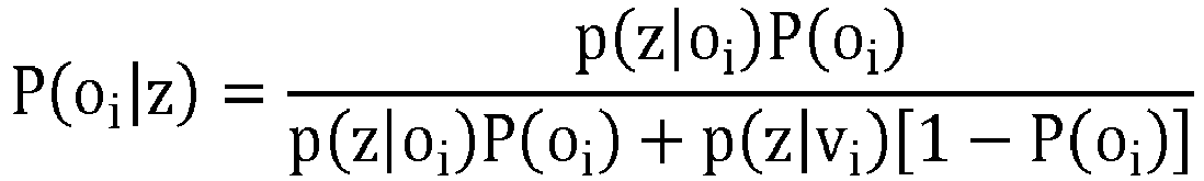
Une mesure z issue d'un capteur permet de déterminer la probabilité d'occupation P(oi|z) d'une cellule ci. Pour une mesure z donnée, l'ensemble des probabilités P(oi|z) ∀ i ∈ [0, N-1 constitue le modèle inverse du capteur sur la grille. Alors que le modèle direct du capteur renseigne sur la réponse du capteur en fonction du monde physique, le modèle inverse exprime l'impact de la mesure sur la grille d'occupation qui est le modèle du monde physique que l'on adopte, ce qui justifie l'appellation modèle inverse.A measurement z from a sensor makes it possible to determine the probability of occupation P (o i | z) of a cell c i . For a given z measurement, the set of probabilities P (o i | z) ∀ i ∈ [0, N-1 constitutes the inverse model of the sensor on the grid. While the sensor's direct model provides information about the sensor's response to the physical world, the inverse model expresses the impact of the measurement on the occupancy grid, which is the model of the physical world that we adopt. justifies the name inverse model.
La
Conformément à l'usage qui prévaut dans la littérature, la
Une version plus juste du modèle inverse de la
Il convient de souligner que les notions de « occupation » et de « distance de l'obstacle » ne sont pas tout à fait équivalentes. En effet, dire qu'un obstacle est à une distance z de capteur ne signifie pas seulement qu'une certaine cellule est occupée, mais aussi que toutes les autres cellules de la grille plus proches du capteur sont libres (autrement, le premier obstacle aurait été vu à une distance inférieure à z). Sur la
Si on tient compte de la notion de capteur incertain caractérisé par son modèle (direct) p(z|![]()
![]()
![]()
![]()
L'équation (2) indique que le modèle du capteur évalué en un point qui est à la frontière d'une cellule de la grille (xi) est égal à la densité de probabilité de réponse du capteur pour une configuration de grille correspondante, à savoir une grille où les cellules les plus proches que la cellule i sont vides, la cellule i est occupée, et les états d'occupation des cellules plus éloignées que la cellule i ne sont pas déterminées. Le modèle inverse du capteur peut être construit en exploitant cette information. Une explication de ce procédé est donnée ci-dessous.Equation (2) indicates that the model of the sensor evaluated at a point which is at the boundary of a grid cell (x i ) is equal to the sensor response probability density for a corresponding grid pattern, that is, a grid where the cells closest to the cell i are empty, the cell i is occupied, and the states of occupation of the cells farther than the cell i are not determined. The inverse model of the sensor can be built using this information. An explanation of this process is given below.
Le théorème de Bayes permet d'exprimer le modèle inverse d'un capteur P(oi|z) de la manière suivante : 
L'équation (3) devient alors : 
Pour pouvoir appliquer l'équation (4) et déterminer effectivement P(oi|z), il faut préalablement calculer les termes p(z|oi) et p(z|vi). Pour cela on considèrera le cas d'une grille unidimensionnelle, mais la généralisation est sans difficulté. Dans le cas où la probabilité d'occupation a priori n'est pas la même pour toutes les cellules, l'équation (4) peut être généralisée sans difficulté : 
Soit « d » la première cellule occupée de la grille (0≤d<N), et P(dk) la probabilité de l'évènement d=k. On peut alors écrire : 
![]()
![]()
Le terme P(dk|oi) prend les valeurs suivantes, en fonction des indices k et i : 
A ce point on introduit l'hypothèse précitée de probabilités a priori égales pour toutes les cellules : ![]()
![]()
En remplaçant (7) et (8) dans (6) on trouve : 
De manière similaire à (6) on peut écrire : ![]()
![]()
Le terme P(dk |vi ) prend les valeurs suivantes, en fonction des indices k et i : 
En remplaçant (11) dans (10) et en introduisant l'hypothèse précitée de probabilités a priori égales pour toutes les cellules : ![]()

![]()
Pour obtenir le modèle inverse, il suffit donc de remplacer (8), (9) et (12) dans (4).To obtain the inverse model, it suffices to replace (8), (9) and (12) in (4).
La construction du modèle inverse dépend fortement de la définition de la grille. Il est donc intéressant d'étudier quel est l'impact d'une variation de résolution spatiale sur le modèle inverse. Les
A partir des modèles inverses de deux capteurs sur une même grille d'occupation, la fusion des données des deux capteurs s'effectue à l'aide de l'équation suivante : 
Dans le cas où la probabilité d'occupation a priori n'est pas la même pour toutes les cellules, l'équation (13) peut être généralisée sans difficulté : 
Appliquer directement l'équation (13) ou (13bis) à la fusion de données issues de plusieurs capteurs est difficilement envisageable dans un système embarqué, car cela nécessiterait l'exécution de nombreux calculs en virgule flottante pour chaque cellule de la grille à une fréquence au moins aussi rapide que la fréquence d'acquisition des capteurs. Une puissance de calcul importante serait dont nécessaire.Applying equation (13) or (13a) directly to the fusion of data from several sensors is difficult to envisage in a embedded system, because this would require the execution of many floating-point calculations for each cell of the grid at a frequency at least as fast as the acquisition frequency of the sensors. An important computing power would be needed.
Conformément à l'approche déjà divulguée par l'article précité de
Dans ce qui suit, on appellera « système de classes de probabilités » ![]()
![]()
![]()
![]()
Dans le cas où la probabilité d'occupation a priori n'est pas la même pour toutes les cellules, l'équation (14) peut être généralisée sans difficulté : ![]()
![]()
Un cas particulièrement intéressant est celui d'un système de classes tel que le résultat de la fusion de deux classes de probabilités du système appartient également au système ; formellement : V pi,pj∈S, F(p1, p2)∈S. On parle alors d'un système de classes « sans erreur », car la fusion n'introduit pas d'erreur ou d'approximation. Il est donc possible de repérer les valeurs de probabilité par les indices des classes correspondantes, et le résultat d'une fusion est également identifié par un indice. Le problème de la fusion revient alors à déterminer une fonction appropriée Fd qui, à deux indices entiers, associe un autre indice entier. Formellement : ![]()
![]()
Le calcul de Fd(k,l) ne requiert que la connaissance des indices k et l et de l'arithmétique d'indice entier ; aucun calcul en virgule flottante n'est nécessaire pour le calcul de la fusion des informations pk et pl . De plus, si le système de classes est considéré sans erreur, l'indice obtenu à l'aide de Fd(k,l) désigne une valeur de probabilité strictement identique à celle obtenue - en utilisant des nombres en virgule flottante - en appliquant l'équation (14). La méthode permet ainsi la fusion des classes de probabilité sans erreur par rapport à un calcul flottant.The computation of F d (k, l) requires only the knowledge of indices k and l and of integer index arithmetic; no floating-point computation is necessary for the computation of the fusion of the information p k and p l . Moreover, if the class system is considered error-free, the index obtained using F d (k, l) designates a probability value strictly identical to that obtained - using floating-point numbers - by applying Equation (14). The method thus makes it possible to merge the probability classes without error with respect to a floating calculation.
Un exemple trivial de système sans erreur est S={1/2, 1}. Tout système de classes sans erreur comprenant des probabilités différentes de 1/2, 1 et 0 comprend nécessairement une infinité d'éléments. En pratique, pour des raisons évidentes de mise en oeuvre, on considèrera uniquement des systèmes de classes de probabilités de cardinalité finie. Toutefois, étant donné que les capteurs sont en nombre fini et que leurs sorties (quantifiées et numérisées) ne peuvent prendre qu'un nombre fini de valeurs, on démontre qu'il est possible de réaliser des fusions « sans erreurs » même à partir de systèmes de classes de probabilités de cardinalité finie.A trivial example of an error-free system is S = {1/2, 1}. Any system of error-free classes with different probabilities of 1/2, 1 and 0 necessarily includes infinitely many elements. In practice, for obvious reasons of implementation, we will consider only systems of classes of probabilities of finite cardinality. However, since the sensors are finite in number and their outputs (quantized and digitized) can only take a finite number of values, it is shown that it is possible to carry out "error-free" mergers even from finite cardinality probability class systems.
Il est important de noter que le modèle inverse de la
Une première possibilité consiste à remplacer les valeurs du modèle inverse par les éléments de S les plus proches, de manière à minimiser l'erreur de quantification. Cette approche peut conduire à sous-estimer la probabilité d'occupation d'une cellule, ce qui peut ne pas être acceptable dans une application de détection d'obstacles. Une alternative consiste à approcher les valeurs du modèle inverse théorique par le plus petit majorant du système de classes S ; ainsi la probabilité d'occupation n'est jamais sous-estimée, ce qui peut être un avantage pour la détection d'obstacles. Dans d'autres applications, comme le comptage de personne, ce type d'approximation peut en revanche conduire à la génération de faux-positifs.A first possibility is to replace the values of the inverse model by the elements of S closest, so as to minimize the quantization error. This approach may lead to underestimation of the probability of occupancy of a cell, which may not be acceptable in an obstacle detection application. An alternative is to approach the values of the theoretical inverse model by the smallest sum of the S class system; so the probability of occupation is never underestimated, which can be an advantage for obstacle detection. In other applications, such as the counting of people, this type of approximation can, on the other hand, lead to the generation of false positives.
Quel que soit le type d'approximation considéré, le système inverse discrétisé spatialement prend un nombre de valeurs qui est très faible (de moins de 10 à quelques dizaines au plus). Par conséquent, le nombre d'éléments du système S nécessaires pour l'approcher le modèle inverse est également très faible. On peut donc se limiter à considérer un sous-ensemble fini, et de petite taille, du système de classes S dont la cardinalité est, en principe, infinie et dénombrable.Whatever the type of approximation considered, the spatially discretized inverse system takes a number of values that is very small (from less than 10 to a few tens at most). Consequently, the number of elements of the system S necessary to approach the inverse model is also very small. We can therefore limit ourselves to considering a finite subset of the class S system whose cardinality is, in principle, infinite and countable.
Il a été montré plus haut, en référence aux
Un système de classes ![]()
![]()
Soit p une probabilité d'occupation strictement comprise entre 0 et 1-P(o). On définit alors par récurrence la suite pn de la façon suivante : 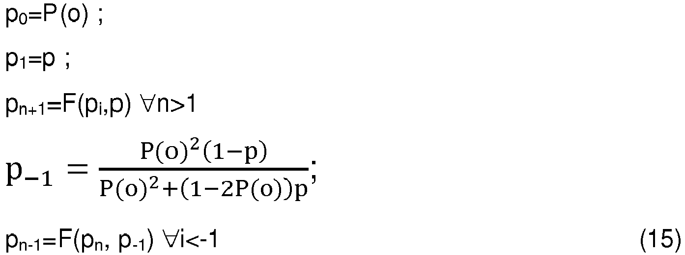
Dans le cas où la probabilité d'occupation a priori n'est pas la même pour toutes les cellules, le système (15) peut être généralisé sans difficulté : 
Par ailleurs le paramètre « p », qui fixe la valeur de p1, peut également être différent d'une cellule à l'autre.Moreover, the parameter "p", which sets the value of p 1 , can also be different from one cell to another.
Par constructions, ces classes sont sans erreur. En effet, si on note fp la fonction à une variable qui, à une probabilité x, associe fp(x)=F(x,p), on voit immédiatement que ![]()
![]()

![]()
![]()
La formule de fusion pour ces classes est extrêmement simple: ![]()
![]()
De plus, le paramètre p permet de contrôler finement l'erreur introduite par la quantification ; en effet si on pose p=1/2 + ε on a : ![]()
![]()
Ce système de classes ![]()
![]()
La ![]()
![]()
![]()
![]()
Le système de classes ![]()


![]()
La
Le véhicule VT est également équipé d'un récepteur radio RR qui reçoit un signal SPO lui permettant de déterminer la valeur de probabilité d'occupation a priori, P(o). Le signal SPO est transmis par une station de surveillance SST qui peut être un centre de contrôle du trafic ou même un équipement autonome de l'infrastructure routière. Ce signal peut directement véhiculer la valeur de P(o), ou bien un paramètre représentatif d'un état de la circulation permettant à un processeur embarqué sur le véhicule de calculer cette valeur.The vehicle VT is also equipped with a radio receiver RR which receives an SPO signal enabling it to determine the occupancy probability value a priori, P (o). The SPO signal is transmitted by an SST monitoring station which may be a traffic control center or even a autonomous equipment of the road infrastructure. This signal can directly convey the value of P (o), or a parameter representative of a state of the circulation allowing a processor on board the vehicle to calculate this value.
La
Dans le mode de réalisation de la
Le module de traitement des données comprend également un registre RPO permettant de stocker une valeur P(o) de la probabilité d'occupation a posteriori. Contrairement au mode de réalisation de la
Chaque bloc de traitement COk reçoit donc en entrée les mesures correspondant à une nappe d'acquisition zk (références z1...zNC) respective ainsi que la valeur P(o) stockée dans le registre RPO, et fournit en sortie une grille d'occupation, sous la forme un vecteur d'entiers gk représentant les indices des classes de probabilités associées aux différentes cellules de la grille. Ainsi, la grille gk renferme les informations d'occupation estimées à l'aide des mesures de la nappe k uniquement, c'est-à-dire du vecteur de mesures zk.Each processing block CO k thus receives, as input, the measurements corresponding to an acquisition layer z k (references z 1 ... z NC ) respectively, as well as the value P (o) stored in the register RPO, and outputs a grid of occupation, in the form of a vector of integers g k representing the indices of the classes of probabilities associated with the different cells of the grid. Thus, the grid g k contains the occupancy information estimated using measurements of the web only k, that is to say the measurement vector z k .
Le bloc matériel de consolidation F est un circuit arithmétique très simple, qui met en oeuvre l'équation (17). Il reçoit à son entrée les grilles d'occupation g1...gNC et fournit à sa sortie une grille d'occupation « consolidée », représentée à son tour par un vecteur d'entiers, indices des classes de probabilités associées aux différentes cellules de cette grille consolidée.The hardware consolidation block F is a very simple arithmetic circuit which implements equation (17). At its input, it receives the occupancy gates g 1 ... g NC and provides at its output a "consolidated" occupation grid, represented in turn by a vector of integers, indices of the classes of probabilities associated with the different cells of this consolidated grid.
Si les modèles inverses associés aux différentes nappes d'acquisition sont identiques, les blocs CO1 ... CONC sont aussi identiques, et peuvent être remplacés par un bloc matériel de calcul de probabilités d'occupation unique, effectuant les traitements de manière séquentielle.If the inverse models associated with the different acquisition plies are identical, the blocks CO 1 ... CO NC are also identical, and can be replaced by a single unit of calculation of occupancy probabilities, performing the treatments sequentially. .
Le module de traitement de données MTD1 peut aussi être associé à tout autre type de capteurs de distance.The data processing module MTD1 can also be associated with any other type of distance sensor.
Les
Dans ce mode de réalisation, la principale difficulté réside dans le fait que la grille d'occupation d'une part et les capteurs d'autres parts ont chacun un repère propre qui leur est associé. Ainsi, l'évaluation de l'emplacement des obstacles requiert d'effectuer des changements de repères.In this embodiment, the main difficulty lies in the fact that the occupancy gate on the one hand and the sensors of other parts each have their own mark associated with them. For example, assessing the location of obstacles requires changes in benchmarks.
La
En variante, les équations de changement de repère peuvent être mémorisées dans des tables de conversion stockées dans des mémoires contenues dans les modules Rk. Ainsi, même dans ce cas, on peut s'affranchir du calcul en virgule flottante et n'effectuer que des opérations sur des entiers. Par contre, ces tables de conversion peuvent être assez volumineuses et leur stockage avoir un coût non négligeable en termes de surface de silicium.As a variant, the reference change equations can be stored in conversion tables stored in memories contained in the modules R k . Thus, even in this case, one can dispense with the floating-point calculation and perform only operations on integers. However, these conversion tables can be quite large and their storage have a significant cost in terms of silicon area.
En outre, contrairement aux deux modes de réalisation précédents, la valeur de la probabilité d'occupation a priori P(o) est calculée par un processeur EPO à partir des données issues d'un capteur CPO distinct des capteurs C1 - CNC fournissant les mesures z. Il peut s'agir par exemple d'un radar non directionnel, émettant une impulsion électromagnétique et comptant le nombre d'échos reçus. Plus ce nombre est important, plus la valeur de P(o) sera élevée.In addition, unlike the two previous embodiments, the value of the prior occupation probability P (o) is calculated by an EPO processor from the data from a sensor C PO distinct from the sensors C 1 -C NC providing the measurements z. It may be for example a non-directional radar emitting an electromagnetic pulse and counting the number of echoes received. The larger the number, the higher the value of P (o).
La
Dans ce mode de réalisation, le processeur EPO calcule la valeur de probabilité d'occupation a priori P(o) en fonction du positionnement spatio-temporel du capteur, c'est-à-dire de sa position et/ou de l'heure du jour. Ces données sont fournies par un dispositif de positionnement POS, tel qu'un récepteur GPS. Comme cela a été expliqué plus haut, la connaissance de la position et/ou de l'heure permet d'estimer une densité de trafic attendue, et donc de choisir une valeur optimale de P(o).In this embodiment, the processor EPO calculates the occupation probability value a priori P (o) as a function of the spatio-temporal positioning of the sensor, that is to say of its position and / or time of the day. This data is provided by a POS positioning device, such as a GPS receiver. As explained above, the knowledge of the position and / or the time makes it possible to estimate an expected traffic density, and therefore to choose an optimum value of P (o).
Plus généralement, le signal reçu de l'extérieur peut être indicatif d'une densité de corps matériels dans une région d'observation du ou des capteurs (par exemple, il peut s'agir d'un niveau de densité de trafic, reçu directement ou estimé à partir du positionnement spatio-temporel des capteurs ou de leurs régions d'observation respectives), et les probabilités d'occupation a priori être calculées à partir de cette densité de corps matériels.More generally, the signal received from the outside may be indicative of a density of material bodies in an observation region of the one or more sensors (for example, it may be a level of traffic density, received directly or estimated from the spatio-temporal positioning of the sensors or their respective observation regions), and the occupancy probabilities a priori be calculated from this density of material bodies.
Différents moyens d'acquérir et/ou calculer la valeur de P(o) ont été décrits en référence à différents modes de réalisation de l'invention. Cependant, chaque mode de réalisation peut utiliser n'importe lequel de ces moyens - voire plusieurs d'entre eux. On peut même envisager d'utiliser des moyens d'acquisition ou calcul différents pour les probabiltiés d'occupation a priori de différentes cellules de la grille. En outre, les moyens décrits ne constituent nullement une liste exhaustive.Various means for acquiring and / or calculating the value of P (o) have been described with reference to various embodiments of the invention. However, each embodiment may use any of these means - or more than one of them. One can even consider using different acquisition or calculation means for the prior occupation probabilities of different cells of the grid. In addition, the means described do not constitute an exhaustive list.
Dans les modes de réalisation des
D'autres systèmes de classes de probabilité que ![]()
![]()
Claims (15)

Applications Claiming Priority (1)
| Application Number | Priority Date | Filing Date | Title |
|---|---|---|---|
| FR1751246A FR3062924B1 (en) | 2017-02-16 | 2017-02-16 | METHOD AND SYSTEM FOR CONTEXTUALIZED PERCEPTION OF MATERIAL BODIES |
Publications (2)
| Publication Number | Publication Date |
|---|---|
| EP3364213A1 true EP3364213A1 (en) | 2018-08-22 |
| EP3364213B1 EP3364213B1 (en) | 2021-08-04 |
Family
ID=59253609
Family Applications (1)
| Application Number | Title | Priority Date | Filing Date |
|---|---|---|---|
| EP18153468.6A Active EP3364213B1 (en) | 2017-02-16 | 2018-01-25 | Method and system for contextualised perception of material bodies |
Country Status (3)
| Country | Link |
|---|---|
| US (1) | US11105911B2 (en) |
| EP (1) | EP3364213B1 (en) |
| FR (1) | FR3062924B1 (en) |
Cited By (4)
| Publication number | Priority date | Publication date | Assignee | Title |
|---|---|---|---|---|
| EP3734388A1 (en) | 2019-04-29 | 2020-11-04 | Commissariat à l'Energie Atomique et aux Energies Alternatives | Method and apparatus for performing simultaneous localization and mapping |
| EP3757601A1 (en) * | 2019-06-28 | 2020-12-30 | Aptiv Technologies Limited | Method and system for mapping a physical environment by means of an occupancy grid |
| EP3968219A1 (en) | 2020-09-14 | 2022-03-16 | Commissariat à l'Energie Atomique et aux Energies Alternatives | Cooperative method and system for detecting material bodies in an environment |
| WO2023222597A1 (en) | 2022-05-17 | 2023-11-23 | Commissariat A L'energie Atomique Et Aux Energies Alternatives | Method and system for perceiving physical bodies, with optimized scanning |
Families Citing this family (4)
| Publication number | Priority date | Publication date | Assignee | Title |
|---|---|---|---|---|
| EP3654064B1 (en) * | 2018-11-16 | 2021-01-13 | Bayerische Motoren Werke Aktiengesellschaft | Apparatus and method for characterizing an object based on measurement samples from one or more location sensors |
| RU2744012C1 (en) | 2019-12-24 | 2021-03-02 | Общество с ограниченной ответственностью "Яндекс Беспилотные Технологии" | Methods and systems for automated determination of objects presence |
| US11631091B2 (en) * | 2020-05-25 | 2023-04-18 | Shopify Inc. | Systems and methods for measuring traffic density in a region |
| FR3116640B1 (en) * | 2020-11-20 | 2023-11-17 | Commissariat Energie Atomique | Iterative method for estimating the movement of a material body by generating a filtered movement grid |
Citations (2)
| Publication number | Priority date | Publication date | Assignee | Title |
|---|---|---|---|---|
| WO2013087067A1 (en) * | 2011-12-14 | 2013-06-20 | Continental Teves Ag & Co. Ohg | Free space information in an occupancy grid as basis for determining a maneuvering space for a vehicle |
| EP2891899A1 (en) * | 2014-01-06 | 2015-07-08 | Honeywell International Inc. | Mathematically combining remote sensing data with different resolution to create 3D maps |
Family Cites Families (6)
| Publication number | Priority date | Publication date | Assignee | Title |
|---|---|---|---|---|
| FR2890774B1 (en) | 2005-09-09 | 2007-11-16 | Inst Nat Rech Inf Automat | VEHICLE DRIVING ASSISANCE METHOD AND IMPROVED ASSOCIATED DEVICE |
| DE102009007395B4 (en) | 2008-03-25 | 2015-11-26 | Volkswagen Ag | Method for map-based environment representation of a vehicle |
| US8106792B2 (en) * | 2009-07-10 | 2012-01-31 | Telcordia Technologies, Inc. | Program and method for adaptive mobile ad-hoc wireless communication |
| US9429650B2 (en) | 2012-08-01 | 2016-08-30 | Gm Global Technology Operations | Fusion of obstacle detection using radar and camera |
| FR3041451B1 (en) | 2015-09-22 | 2018-02-16 | Commissariat A L'energie Atomique Et Aux Energies Alternatives | METHOD AND SYSTEM FOR COLLECTING MATERIAL BODIES |
| US20180203100A1 (en) * | 2017-01-19 | 2018-07-19 | Honeywell International Inc. | Quality metric for ranging sensor in a degraded visual environment for a situational awareness system |
-
2017
- 2017-02-16 FR FR1751246A patent/FR3062924B1/en not_active Expired - Fee Related
-
2018
- 2018-01-25 EP EP18153468.6A patent/EP3364213B1/en active Active
- 2018-02-08 US US15/892,316 patent/US11105911B2/en active Active
Patent Citations (2)
| Publication number | Priority date | Publication date | Assignee | Title |
|---|---|---|---|---|
| WO2013087067A1 (en) * | 2011-12-14 | 2013-06-20 | Continental Teves Ag & Co. Ohg | Free space information in an occupancy grid as basis for determining a maneuvering space for a vehicle |
| EP2891899A1 (en) * | 2014-01-06 | 2015-07-08 | Honeywell International Inc. | Mathematically combining remote sensing data with different resolution to create 3D maps |
Non-Patent Citations (3)
| Title |
|---|
| MANUEL YGUEL ET AL: "Efficient GPU-based Construction of Occupancy Girds Using several Laser Range-finders", INTELLIGENT ROBOTS AND SYSTEMS, 2006 IEEE/RSJ INTERNATIONAL CONFERENCE ON, IEEE, PI, 1 October 2006 (2006-10-01), pages 105 - 110, XP031006221, ISBN: 978-1-4244-0258-8 * |
| RAKOTOVAO TIANA ET AL: "Multi-sensor fusion of occupancy grids based on integer arithmetic", 2016 IEEE INTERNATIONAL CONFERENCE ON ROBOTICS AND AUTOMATION (ICRA), IEEE, 16 May 2016 (2016-05-16), pages 1854 - 1859, XP032908400, DOI: 10.1109/ICRA.2016.7487330 * |
| SCHEUNERT U ET AL: "Generalized Grid Framework for multi sensor data fusion", INFORMATION FUSION, 2008 11TH INTERNATIONAL CONFERENCE ON, IEEE, PISCATAWAY, NJ, USA, 30 June 2008 (2008-06-30), pages 1 - 7, XP031931930, ISBN: 978-3-8007-3092-6 * |
Cited By (8)
| Publication number | Priority date | Publication date | Assignee | Title |
|---|---|---|---|---|
| EP3734388A1 (en) | 2019-04-29 | 2020-11-04 | Commissariat à l'Energie Atomique et aux Energies Alternatives | Method and apparatus for performing simultaneous localization and mapping |
| EP3757601A1 (en) * | 2019-06-28 | 2020-12-30 | Aptiv Technologies Limited | Method and system for mapping a physical environment by means of an occupancy grid |
| FR3097972A1 (en) * | 2019-06-28 | 2021-01-01 | Aptiv Technologies Limited | Method and system for mapping a physical environment using an occupancy grid |
| US11718323B2 (en) | 2019-06-28 | 2023-08-08 | Aptiv Technologies Limited | Method and system for mapping a physical environment using an occupancy grid |
| EP3968219A1 (en) | 2020-09-14 | 2022-03-16 | Commissariat à l'Energie Atomique et aux Energies Alternatives | Cooperative method and system for detecting material bodies in an environment |
| FR3114174A1 (en) | 2020-09-14 | 2022-03-18 | Commissariat A L'energie Atomique Et Aux Energies Alternatives | Method and system for cooperative detection of material bodies in an environment |
| WO2023222597A1 (en) | 2022-05-17 | 2023-11-23 | Commissariat A L'energie Atomique Et Aux Energies Alternatives | Method and system for perceiving physical bodies, with optimized scanning |
| FR3135790A1 (en) | 2022-05-17 | 2023-11-24 | Commissariat A L'energie Atomique Et Aux Energies Alternatives | METHOD AND SYSTEM FOR PERCEPTING MATERIAL BODIES WITH OPTIMIZED SCANNING |
Also Published As
| Publication number | Publication date |
|---|---|
| EP3364213B1 (en) | 2021-08-04 |
| US11105911B2 (en) | 2021-08-31 |
| FR3062924B1 (en) | 2019-04-05 |
| FR3062924A1 (en) | 2018-08-17 |
| US20180231650A1 (en) | 2018-08-16 |
Similar Documents
| Publication | Publication Date | Title |
|---|---|---|
| EP3364213B1 (en) | Method and system for contextualised perception of material bodies | |
| EP3353720B1 (en) | Method and system for perceiving physical bodies | |
| EP3252615B1 (en) | Method and system for determining cells crossed by a measuring or viewing axis | |
| EP2599021B1 (en) | Method for optimally determining the characteristics and arrangement of a set of sensors for monitoring an area | |
| Javanmardi et al. | Factors to evaluate capability of map for vehicle localization | |
| EP3189389B1 (en) | Location and mapping device with associated method | |
| CA2621980A1 (en) | Vehicle steering aid method and improved related device | |
| EP3968219A1 (en) | Cooperative method and system for detecting material bodies in an environment | |
| EP3074892A1 (en) | Method for simulating wave propagation; simulator, computer program and recording medium for implementing the method | |
| FR3096637A1 (en) | Method and device for determining a path for an autonomous vehicle | |
| Chiodini et al. | Evaluation of 3D CNN semantic mapping for rover navigation | |
| EP4002274A1 (en) | Iterative method for estimating the movement of a material body by generating a filtered movement grid | |
| EP3384462B1 (en) | Method for characterising a scene by calculating the 3d orientation | |
| EP3809155B1 (en) | Method for detecting obstacles, associated detection device, detection system and vehicle | |
| WO2021115998A1 (en) | Particle filtering and navigation system using measurement correlation | |
| Zou et al. | Gaussian Process Mapping of Uncertain Building Models with GMM as Prior | |
| FR3135790A1 (en) | METHOD AND SYSTEM FOR PERCEPTING MATERIAL BODIES WITH OPTIMIZED SCANNING | |
| EP3640841B1 (en) | Electronic device and method for monitoring a scene via a set of electronic sensor(s), associated computer program | |
| EP3311365B1 (en) | Method for estimating and forecasting an energy production indicator for a solar system | |
| WO2022129325A1 (en) | Method for computing a path, associated computer program product, information medium and device | |
| WO2021005096A1 (en) | Method for three-dimensional representation of the spatial coverage of one or more detection systems | |
| EP4332914A1 (en) | Method and device for detecting material objects in a space surrounding an autonomous robot | |
| FR3104705A1 (en) | PARTICULAR FILTERING AND NAVIGATION CENTRAL WITH MEASUREMENT CORRELATION | |
| FR3128678A1 (en) | Method and device for trajectory control of an autonomous vehicle | |
| FR3097318A1 (en) | Method and system for determining a route that a motor vehicle must complete within a space based on a moving object in front of it |
Legal Events
| Date | Code | Title | Description |
|---|---|---|---|
| PUAI | Public reference made under article 153(3) epc to a published international application that has entered the european phase |
Free format text: ORIGINAL CODE: 0009012 |
|
| STAA | Information on the status of an ep patent application or granted ep patent |
Free format text: STATUS: REQUEST FOR EXAMINATION WAS MADE |
|
| 17P | Request for examination filed |
Effective date: 20180125 |
|
| AK | Designated contracting states |
Kind code of ref document: A1 Designated state(s): AL AT BE BG CH CY CZ DE DK EE ES FI FR GB GR HR HU IE IS IT LI LT LU LV MC MK MT NL NO PL PT RO RS SE SI SK SM TR |
|
| AX | Request for extension of the european patent |
Extension state: BA ME |
|
| RIC1 | Information provided on ipc code assigned before grant |
Ipc: G01S 13/93 20200101AFI20210311BHEP Ipc: G01S 13/931 20200101ALI20210311BHEP Ipc: G06K 9/00 20060101ALI20210311BHEP |
|
| GRAP | Despatch of communication of intention to grant a patent |
Free format text: ORIGINAL CODE: EPIDOSNIGR1 |
|
| STAA | Information on the status of an ep patent application or granted ep patent |
Free format text: STATUS: GRANT OF PATENT IS INTENDED |
|
| INTG | Intention to grant announced |
Effective date: 20210506 |
|
| GRAS | Grant fee paid |
Free format text: ORIGINAL CODE: EPIDOSNIGR3 |
|
| GRAA | (expected) grant |
Free format text: ORIGINAL CODE: 0009210 |
|
| STAA | Information on the status of an ep patent application or granted ep patent |
Free format text: STATUS: THE PATENT HAS BEEN GRANTED |
|
| AK | Designated contracting states |
Kind code of ref document: B1 Designated state(s): AL AT BE BG CH CY CZ DE DK EE ES FI FR GB GR HR HU IE IS IT LI LT LU LV MC MK MT NL NO PL PT RO RS SE SI SK SM TR |
|
| REG | Reference to a national code |
Ref country code: GB Ref legal event code: FG4D Free format text: NOT ENGLISH |
|
| REG | Reference to a national code |
Ref country code: AT Ref legal event code: REF Ref document number: 1417521 Country of ref document: AT Kind code of ref document: T Effective date: 20210815 |
|
| REG | Reference to a national code |
Ref country code: CH Ref legal event code: EP |
|
| REG | Reference to a national code |
Ref country code: DE Ref legal event code: R096 Ref document number: 602018021016 Country of ref document: DE |
|
| REG | Reference to a national code |
Ref country code: IE Ref legal event code: FG4D Free format text: LANGUAGE OF EP DOCUMENT: FRENCH |
|
| REG | Reference to a national code |
Ref country code: LT Ref legal event code: MG9D |
|
| REG | Reference to a national code |
Ref country code: NL Ref legal event code: MP Effective date: 20210804 |
|
| REG | Reference to a national code |
Ref country code: AT Ref legal event code: MK05 Ref document number: 1417521 Country of ref document: AT Kind code of ref document: T Effective date: 20210804 |
|
| PG25 | Lapsed in a contracting state [announced via postgrant information from national office to epo] |
Ref country code: NO Free format text: LAPSE BECAUSE OF FAILURE TO SUBMIT A TRANSLATION OF THE DESCRIPTION OR TO PAY THE FEE WITHIN THE PRESCRIBED TIME-LIMIT Effective date: 20211104 Ref country code: PT Free format text: LAPSE BECAUSE OF FAILURE TO SUBMIT A TRANSLATION OF THE DESCRIPTION OR TO PAY THE FEE WITHIN THE PRESCRIBED TIME-LIMIT Effective date: 20211206 Ref country code: LT Free format text: LAPSE BECAUSE OF FAILURE TO SUBMIT A TRANSLATION OF THE DESCRIPTION OR TO PAY THE FEE WITHIN THE PRESCRIBED TIME-LIMIT Effective date: 20210804 Ref country code: AT Free format text: LAPSE BECAUSE OF FAILURE TO SUBMIT A TRANSLATION OF THE DESCRIPTION OR TO PAY THE FEE WITHIN THE PRESCRIBED TIME-LIMIT Effective date: 20210804 Ref country code: BG Free format text: LAPSE BECAUSE OF FAILURE TO SUBMIT A TRANSLATION OF THE DESCRIPTION OR TO PAY THE FEE WITHIN THE PRESCRIBED TIME-LIMIT Effective date: 20211104 Ref country code: SE Free format text: LAPSE BECAUSE OF FAILURE TO SUBMIT A TRANSLATION OF THE DESCRIPTION OR TO PAY THE FEE WITHIN THE PRESCRIBED TIME-LIMIT Effective date: 20210804 Ref country code: RS Free format text: LAPSE BECAUSE OF FAILURE TO SUBMIT A TRANSLATION OF THE DESCRIPTION OR TO PAY THE FEE WITHIN THE PRESCRIBED TIME-LIMIT Effective date: 20210804 Ref country code: FI Free format text: LAPSE BECAUSE OF FAILURE TO SUBMIT A TRANSLATION OF THE DESCRIPTION OR TO PAY THE FEE WITHIN THE PRESCRIBED TIME-LIMIT Effective date: 20210804 Ref country code: ES Free format text: LAPSE BECAUSE OF FAILURE TO SUBMIT A TRANSLATION OF THE DESCRIPTION OR TO PAY THE FEE WITHIN THE PRESCRIBED TIME-LIMIT Effective date: 20210804 Ref country code: HR Free format text: LAPSE BECAUSE OF FAILURE TO SUBMIT A TRANSLATION OF THE DESCRIPTION OR TO PAY THE FEE WITHIN THE PRESCRIBED TIME-LIMIT Effective date: 20210804 |
|
| PG25 | Lapsed in a contracting state [announced via postgrant information from national office to epo] |
Ref country code: PL Free format text: LAPSE BECAUSE OF FAILURE TO SUBMIT A TRANSLATION OF THE DESCRIPTION OR TO PAY THE FEE WITHIN THE PRESCRIBED TIME-LIMIT Effective date: 20210804 Ref country code: LV Free format text: LAPSE BECAUSE OF FAILURE TO SUBMIT A TRANSLATION OF THE DESCRIPTION OR TO PAY THE FEE WITHIN THE PRESCRIBED TIME-LIMIT Effective date: 20210804 Ref country code: GR Free format text: LAPSE BECAUSE OF FAILURE TO SUBMIT A TRANSLATION OF THE DESCRIPTION OR TO PAY THE FEE WITHIN THE PRESCRIBED TIME-LIMIT Effective date: 20211105 |
|
| PG25 | Lapsed in a contracting state [announced via postgrant information from national office to epo] |
Ref country code: NL Free format text: LAPSE BECAUSE OF FAILURE TO SUBMIT A TRANSLATION OF THE DESCRIPTION OR TO PAY THE FEE WITHIN THE PRESCRIBED TIME-LIMIT Effective date: 20210804 |
|
| PG25 | Lapsed in a contracting state [announced via postgrant information from national office to epo] |
Ref country code: DK Free format text: LAPSE BECAUSE OF FAILURE TO SUBMIT A TRANSLATION OF THE DESCRIPTION OR TO PAY THE FEE WITHIN THE PRESCRIBED TIME-LIMIT Effective date: 20210804 |
|
| REG | Reference to a national code |
Ref country code: DE Ref legal event code: R097 Ref document number: 602018021016 Country of ref document: DE |
|
| PG25 | Lapsed in a contracting state [announced via postgrant information from national office to epo] |
Ref country code: SM Free format text: LAPSE BECAUSE OF FAILURE TO SUBMIT A TRANSLATION OF THE DESCRIPTION OR TO PAY THE FEE WITHIN THE PRESCRIBED TIME-LIMIT Effective date: 20210804 Ref country code: SK Free format text: LAPSE BECAUSE OF FAILURE TO SUBMIT A TRANSLATION OF THE DESCRIPTION OR TO PAY THE FEE WITHIN THE PRESCRIBED TIME-LIMIT Effective date: 20210804 Ref country code: RO Free format text: LAPSE BECAUSE OF FAILURE TO SUBMIT A TRANSLATION OF THE DESCRIPTION OR TO PAY THE FEE WITHIN THE PRESCRIBED TIME-LIMIT Effective date: 20210804 Ref country code: EE Free format text: LAPSE BECAUSE OF FAILURE TO SUBMIT A TRANSLATION OF THE DESCRIPTION OR TO PAY THE FEE WITHIN THE PRESCRIBED TIME-LIMIT Effective date: 20210804 Ref country code: CZ Free format text: LAPSE BECAUSE OF FAILURE TO SUBMIT A TRANSLATION OF THE DESCRIPTION OR TO PAY THE FEE WITHIN THE PRESCRIBED TIME-LIMIT Effective date: 20210804 Ref country code: AL Free format text: LAPSE BECAUSE OF FAILURE TO SUBMIT A TRANSLATION OF THE DESCRIPTION OR TO PAY THE FEE WITHIN THE PRESCRIBED TIME-LIMIT Effective date: 20210804 |
|
| PLBE | No opposition filed within time limit |
Free format text: ORIGINAL CODE: 0009261 |
|
| STAA | Information on the status of an ep patent application or granted ep patent |
Free format text: STATUS: NO OPPOSITION FILED WITHIN TIME LIMIT |
|
| 26N | No opposition filed |
Effective date: 20220506 |
|
| PG25 | Lapsed in a contracting state [announced via postgrant information from national office to epo] |
Ref country code: IT Free format text: LAPSE BECAUSE OF FAILURE TO SUBMIT A TRANSLATION OF THE DESCRIPTION OR TO PAY THE FEE WITHIN THE PRESCRIBED TIME-LIMIT Effective date: 20210804 |
|
| PG25 | Lapsed in a contracting state [announced via postgrant information from national office to epo] |
Ref country code: SI Free format text: LAPSE BECAUSE OF FAILURE TO SUBMIT A TRANSLATION OF THE DESCRIPTION OR TO PAY THE FEE WITHIN THE PRESCRIBED TIME-LIMIT Effective date: 20210804 Ref country code: MC Free format text: LAPSE BECAUSE OF FAILURE TO SUBMIT A TRANSLATION OF THE DESCRIPTION OR TO PAY THE FEE WITHIN THE PRESCRIBED TIME-LIMIT Effective date: 20210804 |
|
| REG | Reference to a national code |
Ref country code: CH Ref legal event code: PL |
|
| GBPC | Gb: european patent ceased through non-payment of renewal fee |
Effective date: 20220125 |
|
| REG | Reference to a national code |
Ref country code: BE Ref legal event code: MM Effective date: 20220131 |
|
| PG25 | Lapsed in a contracting state [announced via postgrant information from national office to epo] |
Ref country code: LU Free format text: LAPSE BECAUSE OF NON-PAYMENT OF DUE FEES Effective date: 20220125 Ref country code: GB Free format text: LAPSE BECAUSE OF NON-PAYMENT OF DUE FEES Effective date: 20220125 |
|
| PG25 | Lapsed in a contracting state [announced via postgrant information from national office to epo] |
Ref country code: BE Free format text: LAPSE BECAUSE OF NON-PAYMENT OF DUE FEES Effective date: 20220131 |
|
| PG25 | Lapsed in a contracting state [announced via postgrant information from national office to epo] |
Ref country code: LI Free format text: LAPSE BECAUSE OF NON-PAYMENT OF DUE FEES Effective date: 20220131 Ref country code: CH Free format text: LAPSE BECAUSE OF NON-PAYMENT OF DUE FEES Effective date: 20220131 |
|
| PG25 | Lapsed in a contracting state [announced via postgrant information from national office to epo] |
Ref country code: IE Free format text: LAPSE BECAUSE OF NON-PAYMENT OF DUE FEES Effective date: 20220125 |
|
| PGFP | Annual fee paid to national office [announced via postgrant information from national office to epo] |
Ref country code: FR Payment date: 20230123 Year of fee payment: 6 |
|
| PGFP | Annual fee paid to national office [announced via postgrant information from national office to epo] |
Ref country code: DE Payment date: 20230119 Year of fee payment: 6 |
|
| PG25 | Lapsed in a contracting state [announced via postgrant information from national office to epo] |
Ref country code: HU Free format text: LAPSE BECAUSE OF FAILURE TO SUBMIT A TRANSLATION OF THE DESCRIPTION OR TO PAY THE FEE WITHIN THE PRESCRIBED TIME-LIMIT; INVALID AB INITIO Effective date: 20180125 |