EP3364069A1 - Balancer shaft assembly - Google Patents
Balancer shaft assembly Download PDFInfo
- Publication number
- EP3364069A1 EP3364069A1 EP18150063.8A EP18150063A EP3364069A1 EP 3364069 A1 EP3364069 A1 EP 3364069A1 EP 18150063 A EP18150063 A EP 18150063A EP 3364069 A1 EP3364069 A1 EP 3364069A1
- Authority
- EP
- European Patent Office
- Prior art keywords
- balancer shaft
- bearing
- thrust control
- bearing cap
- shaft assembly
- Prior art date
- Legal status (The legal status is an assumption and is not a legal conclusion. Google has not performed a legal analysis and makes no representation as to the accuracy of the status listed.)
- Granted
Links
Images

Classifications
-
- F—MECHANICAL ENGINEERING; LIGHTING; HEATING; WEAPONS; BLASTING
- F16—ENGINEERING ELEMENTS AND UNITS; GENERAL MEASURES FOR PRODUCING AND MAINTAINING EFFECTIVE FUNCTIONING OF MACHINES OR INSTALLATIONS; THERMAL INSULATION IN GENERAL
- F16F—SPRINGS; SHOCK-ABSORBERS; MEANS FOR DAMPING VIBRATION
- F16F15/00—Suppression of vibrations in systems; Means or arrangements for avoiding or reducing out-of-balance forces, e.g. due to motion
- F16F15/22—Compensation of inertia forces
- F16F15/26—Compensation of inertia forces of crankshaft systems using solid masses, other than the ordinary pistons, moving with the system, i.e. masses connected through a kinematic mechanism or gear system
- F16F15/264—Rotating balancer shafts
- F16F15/267—Rotating balancer shafts characterised by bearing support of balancer shafts; Lubrication arrangements
-
- F—MECHANICAL ENGINEERING; LIGHTING; HEATING; WEAPONS; BLASTING
- F02—COMBUSTION ENGINES; HOT-GAS OR COMBUSTION-PRODUCT ENGINE PLANTS
- F02B—INTERNAL-COMBUSTION PISTON ENGINES; COMBUSTION ENGINES IN GENERAL
- F02B75/00—Other engines
- F02B75/06—Engines with means for equalising torque
-
- F—MECHANICAL ENGINEERING; LIGHTING; HEATING; WEAPONS; BLASTING
- F16—ENGINEERING ELEMENTS AND UNITS; GENERAL MEASURES FOR PRODUCING AND MAINTAINING EFFECTIVE FUNCTIONING OF MACHINES OR INSTALLATIONS; THERMAL INSULATION IN GENERAL
- F16C—SHAFTS; FLEXIBLE SHAFTS; ELEMENTS OR CRANKSHAFT MECHANISMS; ROTARY BODIES OTHER THAN GEARING ELEMENTS; BEARINGS
- F16C17/00—Sliding-contact bearings for exclusively rotary movement
- F16C17/02—Sliding-contact bearings for exclusively rotary movement for radial load only
-
- F—MECHANICAL ENGINEERING; LIGHTING; HEATING; WEAPONS; BLASTING
- F16—ENGINEERING ELEMENTS AND UNITS; GENERAL MEASURES FOR PRODUCING AND MAINTAINING EFFECTIVE FUNCTIONING OF MACHINES OR INSTALLATIONS; THERMAL INSULATION IN GENERAL
- F16C—SHAFTS; FLEXIBLE SHAFTS; ELEMENTS OR CRANKSHAFT MECHANISMS; ROTARY BODIES OTHER THAN GEARING ELEMENTS; BEARINGS
- F16C17/00—Sliding-contact bearings for exclusively rotary movement
- F16C17/10—Sliding-contact bearings for exclusively rotary movement for both radial and axial load
-
- F—MECHANICAL ENGINEERING; LIGHTING; HEATING; WEAPONS; BLASTING
- F16—ENGINEERING ELEMENTS AND UNITS; GENERAL MEASURES FOR PRODUCING AND MAINTAINING EFFECTIVE FUNCTIONING OF MACHINES OR INSTALLATIONS; THERMAL INSULATION IN GENERAL
- F16C—SHAFTS; FLEXIBLE SHAFTS; ELEMENTS OR CRANKSHAFT MECHANISMS; ROTARY BODIES OTHER THAN GEARING ELEMENTS; BEARINGS
- F16C3/00—Shafts; Axles; Cranks; Eccentrics
- F16C3/04—Crankshafts, eccentric-shafts; Cranks, eccentrics
- F16C3/18—Eccentric-shafts
-
- F—MECHANICAL ENGINEERING; LIGHTING; HEATING; WEAPONS; BLASTING
- F16—ENGINEERING ELEMENTS AND UNITS; GENERAL MEASURES FOR PRODUCING AND MAINTAINING EFFECTIVE FUNCTIONING OF MACHINES OR INSTALLATIONS; THERMAL INSULATION IN GENERAL
- F16C—SHAFTS; FLEXIBLE SHAFTS; ELEMENTS OR CRANKSHAFT MECHANISMS; ROTARY BODIES OTHER THAN GEARING ELEMENTS; BEARINGS
- F16C33/00—Parts of bearings; Special methods for making bearings or parts thereof
- F16C33/02—Parts of sliding-contact bearings
- F16C33/04—Brasses; Bushes; Linings
- F16C33/046—Brasses; Bushes; Linings divided or split, e.g. half-bearings or rolled sleeves
-
- F—MECHANICAL ENGINEERING; LIGHTING; HEATING; WEAPONS; BLASTING
- F16—ENGINEERING ELEMENTS AND UNITS; GENERAL MEASURES FOR PRODUCING AND MAINTAINING EFFECTIVE FUNCTIONING OF MACHINES OR INSTALLATIONS; THERMAL INSULATION IN GENERAL
- F16F—SPRINGS; SHOCK-ABSORBERS; MEANS FOR DAMPING VIBRATION
- F16F15/00—Suppression of vibrations in systems; Means or arrangements for avoiding or reducing out-of-balance forces, e.g. due to motion
- F16F15/22—Compensation of inertia forces
- F16F15/26—Compensation of inertia forces of crankshaft systems using solid masses, other than the ordinary pistons, moving with the system, i.e. masses connected through a kinematic mechanism or gear system
- F16F15/264—Rotating balancer shafts
-
- F—MECHANICAL ENGINEERING; LIGHTING; HEATING; WEAPONS; BLASTING
- F16—ENGINEERING ELEMENTS AND UNITS; GENERAL MEASURES FOR PRODUCING AND MAINTAINING EFFECTIVE FUNCTIONING OF MACHINES OR INSTALLATIONS; THERMAL INSULATION IN GENERAL
- F16C—SHAFTS; FLEXIBLE SHAFTS; ELEMENTS OR CRANKSHAFT MECHANISMS; ROTARY BODIES OTHER THAN GEARING ELEMENTS; BEARINGS
- F16C2326/00—Articles relating to transporting
- F16C2326/01—Parts of vehicles in general
- F16C2326/05—Vehicle suspensions, e.g. bearings, pivots or connecting rods used therein
-
- F—MECHANICAL ENGINEERING; LIGHTING; HEATING; WEAPONS; BLASTING
- F16—ENGINEERING ELEMENTS AND UNITS; GENERAL MEASURES FOR PRODUCING AND MAINTAINING EFFECTIVE FUNCTIONING OF MACHINES OR INSTALLATIONS; THERMAL INSULATION IN GENERAL
- F16C—SHAFTS; FLEXIBLE SHAFTS; ELEMENTS OR CRANKSHAFT MECHANISMS; ROTARY BODIES OTHER THAN GEARING ELEMENTS; BEARINGS
- F16C2360/00—Engines or pumps
- F16C2360/22—Internal combustion engines
-
- F—MECHANICAL ENGINEERING; LIGHTING; HEATING; WEAPONS; BLASTING
- F16—ENGINEERING ELEMENTS AND UNITS; GENERAL MEASURES FOR PRODUCING AND MAINTAINING EFFECTIVE FUNCTIONING OF MACHINES OR INSTALLATIONS; THERMAL INSULATION IN GENERAL
- F16F—SPRINGS; SHOCK-ABSORBERS; MEANS FOR DAMPING VIBRATION
- F16F2230/00—Purpose; Design features
- F16F2230/04—Lubrication
Definitions
- This disclosure relates to balancer shafts for an internal combustion engine of a vehicle, and in particular to thrust control of balancer shafts in an internal combustion engine.
- a modern internal combustion engine has many moving parts, such as reciprocating and rotating parts, which cause unbalanced forces to be exerted on the engine. It is generally desirable to cancel or balance these forces where possible to extend the life of the engine and its components and to improve the comfort of users of the vehicle.
- Balancing of the engine forces is often achieved with one or more balancer shafts which comprise eccentrically weighted components.
- the eccentrically weighted components are designed to apply equal and opposite forces to those exerted on the engine by other components when the balancer shaft is rotated.
- the net reciprocating forces applied to the engine during operation may be substantially reduced.
- balancer shafts are eccentrically weighted by design, axial forces may be present which may cause the balancer shaft to shift in an axial direction. Axial forces can also be applied to the balancer shaft by the driving mechanism of the shaft, such as helical gears. In order to reduce or prevent this movement, balancer shafts require thrust control.
- a balancer shaft assembly for an internal combustion engine comprising: a bearing cap and a balancer shaft configured to rotate within a bearing comprising the bearing cap.
- the bearing cap comprises first and second thrust control faces on opposing sides of the bearing cap.
- the balancer shaft comprises first and second components, at least one of the first and second components being operable to balance the internal combustion engine.
- the first and second components are arranged on the opposing sides of the bearing cap to thereby constrain axial movement of the balancer shaft.
- the thrust control bearing cap provides a lubricated bearing for the balancer shaft in combination with thrust control of the balancer shaft.
- thrust control of the balancer shaft.
- the combining of the thrust control into the bearing cap provides a significant space-saving and weight advantage.
- a balancer shaft is a shaft for rotation within an internal combustion engine to balance forces generated by the movement of other components of the engine.
- two balancer shafts are provided. In such cases, the balancer shafts may rotate in opposite directions to cancel out lateral forces created by their rotation.
- the balancer shaft or shafts may comprise an eccentric weight.
- the eccentric weight may be a mass which is deliberately asymmetric about the circumference of the shaft such that when the shaft rotates in isolation, a force is exerted in the radial direction.
- the eccentric weight may be formed as a separate component and then attached to the balancer shaft, or the weight may be formed integrally as part of the shaft, for example by casting.
- the shaft or shafts may be arranged to rotate within one or more bearings.
- the bearings may be formed in two parts, with a bearing seat portion formed integrally to the engine forming a part of the bearing surface, and a bearing cap fixable to the engine to complete the bearing surface about the balancer shaft and to secure the balancer shaft to the engine in a freely-rotatable manner.
- the bearing cap may be secured to the bearing seat by temporary fixings, such as bolts or screws, to thereby facilitate removal of the shaft if required.
- the thrust control faces of the bearing cap may extend about an arc of a circumference of the balancer shaft, for example around a 180 degree arc.
- the thrust control faces of the bearing cap may comprise a point or line face for contact with the thrust control face of the first or second component.
- the thrust control faces of the bearing cap may be formed in a plane substantially perpendicular to a longitudinal or rotation axis of the balancer shaft.
- the bearing seat may comprise a thrust control face which, when the bearing cap is secured to the bearing seat, in combination form a substantially continuous thrust control face about the balancer shaft.
- the first and second components may be operative components. That is, it should be understood that the first and second components of the present disclosure may be components forming a part of the balancer shaft which have a primary function which is not related to effecting thrust control of the shaft.
- At least one of the first and second components may comprise a component thrust control face for sliding contact with one of the first and second thrust control faces of the bearing cap.
- the thrust control face of the first or second component may be formed continuously around an entire circumference of the balancer shaft.
- At least one of the first and second components may be an eccentric balancing weight.
- the eccentric balancing weight may comprise a weight thrust control face adapted for sliding contact with one of the first and second thrust control faces of the bearing cap.
- At least one of the first and second components may be a driven gear of the balancer shaft or a driving gear of the balancer shaft.
- the driven gear or driving gear may comprise a gear thrust control face adapted for sliding contact with one of the first and second thrust control faces of the bearing cap.
- the first and second thrust control faces may form the extreme axial faces of the bearing cap.
- At least one of the first and second thrust control faces of the bearing cap may comprise a groove.
- Any of the thrust control faces of the bearing cap, the first or second component, the eccentric weight, or the driven or driving gear may comprise a groove.
- the groove may be for improving lubrication of the thrust control faces.
- At least one of the first and second thrust control faces comprises a plurality of grooves. More generally, any of the thrust control faces herein described may comprise a plurality of grooves.
- the or each groove may a substantially radially extending groove.
- the groove may extend across a surface of the thrust control face.
- any of the thrust control faces herein described may comprise radially inner or innermost edge and a radially outer or outermost edge.
- the groove or grooves may extend from a radially inner or innermost most edge of the thrust control face.
- the groove or grooves may extend partially across the thrust control face. That is, the groove may extend from the radially inner or innermost edge of the thrust control face radially, but not so far as to reach the radially outer or outermost edge.
- the groove may extend radially inwards from the radially outer or outermost edge, but not so far as to reach the radially inner or innermost edge.
- the groove may extend across the thrust control face to a radially outer or outermost edge of the thrust control face. That is, the groove may extend radially across an entire radial width of the thrust control face from a radially inner face to a radially outer face.
- the thrust control of the balancer shaft may be provided exclusively by the thrust control faces of the bearing cap. That is, the axial movement of the balancer shaft may be provided solely by the bearing cap. It should be understood that when the thrust face of one of the first and second components travels in the axial direction and comes into contact with one of the first and second thrust control faces of the bearing cap, the component - and thus the balancer shaft - may move no further in that axial direction.
- the bearing may further comprise a bearing seat.
- the bearing seat and the bearing cap may, in combination, form the bearing.
- the bearing may comprise a bearing surface for contact with a journal portion of the balancer shaft.
- Each of the bearing seat and the bearing cap may comprise a partial bearing surface which, in combination, form the bearing surface.
- the bearing seat may be formed integrally to a casing portion of an engine, such as a ladderframe of an engine.
- the thrust control faces of the bearing cap may overhang a support structure which receives the bearing cap.
- the support structure may be the bearing seat.
- the bearing cap may have a width in an axial direction of the balancer shaft.
- the bearing cap width may be a width between the thrust control faces of the bearing cap.
- the bearing seat may have a width in the axial direction of the balancer shaft.
- the bearing cap width may be greater than the bearing seat width.
- the balancer shaft assembly may further comprise a second bearing cap and a second balancer shaft, the second balancer shaft configured to rotate in an opposite direction to a rotation direction of the balancer shaft.
- balancer shaft assemblies may comprise first and second balancer shafts which rotate in opposite directions to cancel out transverse or lateral forces caused by the rotating weights on the shafts.
- Each of the balancer shafts may comprise a driven gear for being driven to rotate the balancer shaft.
- the driven gear may be rotated by an external source, such as a linkage to the output shaft of the engine or other source.
- One of the balancer shafts may comprise a driving gear for driving the driven gear of other balancer shaft.
- Each balancer shaft may comprise first and second bearing caps of the type hereinbefore described.
- an internal combustion engine comprising a balancer shaft assembly as hereinbefore described.
- a casing of the engine for example a ladderframe of the engine may comprise the balancer shaft assembly.
- a vehicle comprising a balancer shaft assembly as hereinbefore described.
- the present disclosure provides a balancer shaft assembly 10, for example a balancer shaft assembly for an internal combustion engine of a vehicle.
- vehicle may be any type of vehicle, such a car, a van, a truck, a marine vessel or an aircraft.
- the balancer shaft assembly may be configured for use in a building, and/or in any context.
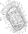
- FIGS 1 and 2 show a balancer shaft assembly 10 in an internal combustion engine 100.
- the engine 100 is partially cut-away to expose a portion 102 of the engine casing for supporting the balancer shaft assembly 10.
- the portion 102 in this case is a ladderframe assembly 102 for supporting the balancer shaft assembly.
- alternative configurations of an engine 100 are available having different arrangements for supporting the balancer shaft assembly 10.
- the ladderframe assembly 102 comprises a pair of opposing side rails 104, and a pair of opposing end rails 106 forming substantially rectangular frame.
- a plurality of cross members 108 extend between the side rails 104 to form a substantially ladder-shaped frame.
- the engine 100 has various reinforcement struts 110 extending between the rails 104,106 and the cross members 108 to provide additional strength to the ladderframe 102.
- the ladderframe 102 is connected to an upper portion of the engine 100 (not shown).
- Various through-holes 112 are provided about the ladderframe 102 for bolting the ladderframe to the engine casing.
- a gasket 114 extends around the rail 104,106 to form a seal between the ladderframe 102 and the remainder of the engine casing.
- Each of the cross-members 108a and 108b comprise a bearing 12 and 14 respectively for rotatably mounting a balancer shaft 16.
- the balancer shaft 16 has numerous components provided thereon for exerting balancing forces and for facilitating rotation of the balancer shaft 16.
- balancer shaft 16 comprises an elongate shaft portion 28 having a first eccentric weight 30 at a first end thereof, and a second, smaller eccentric weight 32 at a second end thereof.
- the weights 30, 32 are examples of components which are operable to balance the internal combustion engine.
- the eccentric weights 30, 32 respectively are located inside the bearings 12, 14 when the balancer shaft 16 is secured in the bearings.
- the eccentric weights 30, 32 exert eccentric forces on the engine when the balancer shaft 16 is rotated, which can be used to balance other forces in the engine as is known in the art.
- the eccentric weights 30, 32 may be integrally formed on the balancer shaft 16, for example by casting, or may be separate components which are fixed to the balancer shaft, for example by an interference fit, or the like.
- journal surfaces 18 of the shaft 16 are the portions of the balancer shaft which make contact with the bearing surfaces 19, 21 of the bearings 12, 14.
- the journals surfaces 18 are smooth, cylindrical portions of the shaft 16 which have an outer diameter substantially similar to or fractionally smaller than an inner diameter of the bearing surfaces 19, 21, such that the balancer shaft 16 can freely rotate within and be supported by the bearings 12, 14 on the journal surfaces.
- the balancer shaft 16 further comprises a driven gear 34 arranged axially outside the eccentric weight 32 and the journal surface 18.
- the driven gear 34 is eccentrically weighted and formed as a separate component to the balancer shaft 16, but is fixed to the balancer shaft 16 by an interference fit or the like.
- the driven gear 34 is a further example of a component operable to balance the internal combustion engine.
- the driven gear 34 in use, meshes with a driving mechanism (not shown) for rotating the balancer shaft 16.
- the driving mechanism may be, for example a gear train from the crankshaft of the engine 100.
- the bearings 12, 14 are provided approximately at the mid-way point along the cross members 108a, b, such that the balancer shaft 16 is arranged parallel to and substantially equidistant from the side rails 104 of the ladderframe 102. In this way, the balancer shaft 16 is provided along an axial centreline of the engine.
- the axis A of the balancer shaft may be parallel to an axis of the crankshaft of the engine 100 (not shown).
- the bearings 12 and 14 are lubricated plain journal bearings.
- the balancer shaft 16 comprises journal surfaces 18 (see Figure 2 ) which rotate within the bearings 12 and 14 against bearing surfaces 19 and 21 respectively of the bearings 12 and 14.
- a lubricant such as oil, is provided between the bearing surface pairs 18, 19 and 18, 21 to facilitate smooth and substantially free rotation of the balancer shaft 16 with respect to the ladderframe 102.
- a bearing shell may be provided between the bearing surfaces 19, 21 and the journal surfaces 18.
- Each of the bearings 12, 14 is formed of a bearing seat 20 and a bearing cap.
- the bearing cap is a thrust control bearing cap 22 and, for bearing 14, the bearing cap is a conventional bearing cap 24. It should be understood that bearing cap 24 of bearing 14 could also be a thrust control bearing cap if desired.
- Both of the bearing seats 20 are substantially similar.
- the seats 20 each comprise a semi-cylindrical recess which forms a seat bearing surface 23 having a radius substantially equal or slightly larger than an outer radius of the journal surface 18 of the balancer shaft 16.
- the seat bearing surface 23 forms half of the circumference or a 180 degree arc of the bearing surfaces 19, 21.
- the other half or 180 degrees of the bearing surfaces 19, 21 is formed by the bearing caps 22, 24 as will be discussed below.
- the bearing seat 20 has a width W B which is less than a width of the journal surface 18 of the balancer shaft 16. Furthermore, the width W B is also less than a width W T of the bearing cap 22 which will be discussed in more detail below. As the width of the bearing seat 20 is less than the width of the bearing cap 22, the bearing cap may be subject to all of the wear relating to thrust control of the balancer shaft 16. Therefore, wear is concentrated on a relatively small and easily replaceable component, rather than an integral part of the ladderframe, which is more expensive and difficult to replace.
- the bearing seats 20 comprise a threaded hole (not shown) arranged either side thereof for receiving a bolt 26 for securing the bearing cap 22, 24 to the bearing seat.
- the conventional bearing cap 24 of bearing 14 comprises a semi-cylindrical recess for forming the other half of the bearing surface 21.
- the radially innermost surface of the cap 24 which forms a portion, in this case a 180 degree arc, of the bearing surface 21 of the bearing 14 in a similar manner to the seat 20.
- he bearing cap 24 comprises a pair of cap mounts 37 having a pair of through bores (not shown) arranged either side of the cap for receiving the bolts 26 for securing the bearing cap 24 to the bearing seat 20 of the bearing 14 to form the complete bearing surface 21 about one of the journal surfaces 18 of the balancer shaft 16.
- the balancing forces exerted by the journal surface 18 of the rotating balancer shaft 16 are reacted by the bearing surface 21 of the bearing 14 to transfer the balancing forces to the engine 100.
- the bearing surface 21 is formed in two parts by the bearing seat 20 and bearing cap 24, it will be understood that a small break or gap is present in the bearing surface 21 where the seat 20 and cap 24 meet.
- manufacturing tolerances used when producing the seat and cap are sufficiently accurate to minimise any such gap such that it does not have a material effect on the smooth operation of the bearing 14.
- the bearing surface 21 is a substantially continuous cylindrical surface despite any small gap being present.
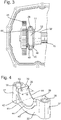
- a first example of the thrust control bearing cap 22 is illustrated in more detail in Figures 2 , 3, and 4 .
- the thrust control bearing cap 22 is formed as a unitary piece by casting, sintering, or the like. Further machining operations may be performed on the thrust control bearing cap after forming to improve the quality or finish of various features, such as the semi-cylindrical cap bearing surface 36, which forms a portion of the bearing surface 19 of the bearing 12.
- the thrust control bearing cap 22 comprises first and second spaced-apart cap mounts 37.
- the cap mounts 37 are substantially cylindrical member having bolt-receiving bores 38 formed therein. When the cap 22 is fixed to the bearing seat 20, the bolts 26 extend through the bores 38 and are secured in threaded holes provided in the seat 20 as discussed above.
- the mounts 37 are connected by structural bridge 40 and a bearing flange 42 formed therebetween.
- the structural bridge 40 is formed radially outwards of the bearing flange 42. Both the bridge 40 and the flange 42 have a substantially arcuate shape with a centre of curvature on the axis A of the balancer shaft 16 when the cap 22 is secured to the seat 20.
- the radially innermost surface of the bearing flange 42 is a cap bearing surface 36 which forms a portion, in this case a 180 degree arc, of the bearing surface 19 of the bearing 12.
- the inner radius of the cap bearing surface 36, and thus the bearing surface 19, is substantially equal or slightly larger than an outer radius of the journal surface 18 of the balancer shaft 16.
- the bearing flange 42 comprises thrust control faces 44 on the extreme axial faces thereof.
- the width of the bridge 40 in an axial direction of the bearing 12 is narrower than a width W T of the bearing flange 42 between the thrust control faces 44.
- a wedge-shaped slot 50 having a reducing depth 50 is formed into the cap bearing surface 36 at one end of the bearing flange 42.
- the slot 50 may be used to locate a bearing shell, if provided, properly in position. In such examples, there may be a complimentary protrusion on the shell which is located in the slot 50.
- a concentric groove may run around the circumference of the bearing surface 19 or of a bearing shell, if provided, for feeding lubricating fluid to the bearing at high pressure.
- a chamfered edge surface 41 is formed between the cap bearing surface 36 and each of the thrust control faces 44 about their entire arc. The chamfer of the surface encourages lubricating fluid from the bearing surface 21 to travel to the thrust control faces 44 to improve their lubrication.
- the end surface of the mounts 37 and the ends of the arced bearing flange 42 form two planar engagement surfaces 39 for contact with corresponding surfaces of the bearing seat 20 (not shown) when the cap 12 is secured to the seat 20.
- the thrust control faces 44 of the bearing cap 22 form the extreme axial faces of the bearing cap 22, and of the bearing 12, in the axial direction A of the balancer shaft 16.
- the thrust control faces 44 of bearing cap 22 are smooth radially extending surfaces formed in a plane perpendicular to the axis A.
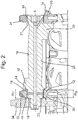
- eccentric weight 32 and the driven gear 34 are arranged either side of the bearing 12 and the bearing cap 22.
- the thrust control faces 44 are arranged on opposing sides of the bearing cap 22 facing the eccentric weight 32 and the driven gear 34.
- the eccentric weight 32 comprises an axially extending thrust face 46 formed adjacent and perpendicular to the journal surface 18.
- the weight thrust surface 46 is formed 360 degrees about the shaft 16 and faces one of the thrust faces 44 of the bearing cap 22 when the balancer shaft 16 is arranged within the bearing 12.
- the weight thrust surface 46 forms an extreme axial face of the eccentric weight 32 in the axial direction A towards the bearing 12.
- the driven gear 34 comprises an axially extending thrust face 48, which is formed adjacent an opposite side of the journal surface 18 and similarly perpendicular thereto.
- the gear thrust surface 48 is also formed about 360 of the shaft 16 and faces opposite thrust face 44 of the bearing cap 22 to the eccentric weight 32.
- the gear thrust surface 48 forms an extreme axial face of the driven gear 34 in the axial direction A towards the bearing 12.
- the weight and gear thrust faces 46, 48 can be said to define the axial limits of the journal surface 18.
- the bearing cap 22 is arranged between the weight and gear thrust faces 46, 48.
- the thrust control faces 44 as discussed above, are spaced apart by an axial distance W T , which is also equivalent to the width of the cap 22.
- the weight and gear thrust faces 46, 48 are spaced apart by an axial distance W X (not shown) which may be substantially equal to W T or slightly larger than W T . If W X is equal to W T , then the thrust control faces 44 will be simultaneously in sliding contact with the weight and gear thrust faces 46, 48, whereas if W X is larger than W T , a small gap will be present between the thrust control faces 44 and the weight and gear thrust faces 46, 48.
- the gap distance W D can be carefully controlled so as to provide clearance between the thrust control faces 44 and the weight and gear thrust faces 46, 48 to permit relatively free and uninhibited rotation of the balancer shaft 16, while preventing significant axial movement of the shaft 16.
- This control of the axial movement of the balancer shaft 16 relative to the bearing 12 is known as thrust control.
- the thrust control faces 44 do not need to be formed around an entire circumference or 360 degrees of the shaft, so the thrust control faces 44 may be formed only on the bearing cap 22 and not on the bearing seat 20.
- the bearing seat 20 may be of a narrower width W B than the bearing cap width W T .
- the thrust control faces of the arrangement of Figures 2 to 6 extends around 180 degrees of the shaft, it will be understood that the surface may extend more or less than this distance.
- the thrust control faces 44 on the bearing cap 22 may even be infinitesimally small area surfaces, such as a line or point formed at an axially extreme location of the bearing cap, and still provide the same technical effect of effecting thrust control using the bearing cap.
- a chamfer is provided between surfaces 44 and 39. This chamber can avoid the edges of the thrust control faces 44 having a sharp edge against the rotating weight and gear thrust faces 46, 48, which might otherwise increase wear on the opposite surfaces.
- the chamfer also provides a wedge area where oil can be trapped between surfaces 46, 48 and the bearing cap 22, which may help create a consistent oil film between the two components.
- a balancer shaft assembly according to the present disclosure provides the dual functions of bearing and thrust control without separate dedicated components. This may enable the balancer shaft assembly to be packaged smaller than would otherwise be possible with conventional thrust control systems.
- FIG. 5 and 6 A second example of a bearing cap 222 for bearing 12 is illustrated in Figures 5 and 6 .
- the bearing cap 22 has a form similar to the bearing cap 22 and like features of the cap 222 to the cap 22 are illustrated with numerals separated from those of Figure 4 by two hundred.
- the bearing cap 222 differs from the cap 22 in that it features a plurality of grooves 252 formed in the thrust control faces 244. Each groove 252 extends from an inner radial edge 254 of the thrust control face 244 to the outer radial edge 256 of the thrust control face 244. However, it will be understood that the grooves 252 may alternatively extend from the inner radial edge 254 across the surface, but end radially inwards of the outer radial surface 256.
- each thrust control face 244 of the bearing cap 222 is equally spaced between a centre line of the bearing flange 242 and from the bearing cap mounts 237. It should be understood that in other examples, one, three, four, five, or more grooves may be provided.
- the grooves 252 are formed as recesses or slots in the surface 244.
- the grooves 252 form a curved or smoothed recessed profile having radiused or chamfered edges such that there are no sharp edges present at an interface between the grooves 252 and the remainder of the thrust control face 244 on which the grooves are formed.
- the grooves 252 are parallel to the bores 238. It should be understood that although the grooves 252 of the illustrated example do not extend exactly along a radial direction with respect to the shaft 16, they may still be considered to be substantially radially extending. That is, they extend from a radially inner position to a radially outer position across the thrust control face 244. In other examples, the grooves 252 may extend along an exact radial direction.
- the grooves 252 improve lubrication of the thrust control faces 244.
- Lubrication fluid such as oil
- the fluid can travel into and along the grooves 252 from the cap bearing surface 236 with less resistance.
- the grooves 252 are filled with lubricating fluid, the fluid directly contacts the thrust face of the adjacent component, such as the weight thrust face 46, as it rotates past the grooves 252.
- the fluid can then form a film on the thrust face of the component as it is rotating past the grooves 252, whereby improving lubrication between the entire thrust control face 244 and the thrust face of the adjacent component, such as the weight 32 or the gear 34.
Landscapes
- Engineering & Computer Science (AREA)
- General Engineering & Computer Science (AREA)
- Mechanical Engineering (AREA)
- Physics & Mathematics (AREA)
- Acoustics & Sound (AREA)
- Aviation & Aerospace Engineering (AREA)
- Ocean & Marine Engineering (AREA)
- Chemical & Material Sciences (AREA)
- Combustion & Propulsion (AREA)
- Sliding-Contact Bearings (AREA)
- Shafts, Cranks, Connecting Bars, And Related Bearings (AREA)
- Lubrication Of Internal Combustion Engines (AREA)
- Centrifugal Separators (AREA)
- Support Of The Bearing (AREA)
Abstract
Description
- This disclosure relates to balancer shafts for an internal combustion engine of a vehicle, and in particular to thrust control of balancer shafts in an internal combustion engine.
- A modern internal combustion engine has many moving parts, such as reciprocating and rotating parts, which cause unbalanced forces to be exerted on the engine. It is generally desirable to cancel or balance these forces where possible to extend the life of the engine and its components and to improve the comfort of users of the vehicle.
- Balancing of the engine forces is often achieved with one or more balancer shafts which comprise eccentrically weighted components. The eccentrically weighted components are designed to apply equal and opposite forces to those exerted on the engine by other components when the balancer shaft is rotated. Thus, the net reciprocating forces applied to the engine during operation may be substantially reduced.
- As balancer shafts are eccentrically weighted by design, axial forces may be present which may cause the balancer shaft to shift in an axial direction. Axial forces can also be applied to the balancer shaft by the driving mechanism of the shaft, such as helical gears. In order to reduce or prevent this movement, balancer shafts require thrust control.
- In view of the numerous constraints applied to the design of modern internal combustion engines, it will be understood that improvements in the field of thrust control of balancer shafts are desirable.
- According to an aspect of the present disclosure, there is provided a balancer shaft assembly for an internal combustion engine comprising: a bearing cap and a balancer shaft configured to rotate within a bearing comprising the bearing cap. The bearing cap comprises first and second thrust control faces on opposing sides of the bearing cap. The balancer shaft comprises first and second components, at least one of the first and second components being operable to balance the internal combustion engine. The first and second components are arranged on the opposing sides of the bearing cap to thereby constrain axial movement of the balancer shaft.
- The thrust control bearing cap according to the present disclosure provides a lubricated bearing for the balancer shaft in combination with thrust control of the balancer shaft. In modern engines, there are numerous conflicting packaging constraints in the lower end of the engine which do not permit the use of conventional thrust control features. Thus, the combining of the thrust control into the bearing cap provides a significant space-saving and weight advantage.
- It should be understood that a balancer shaft is a shaft for rotation within an internal combustion engine to balance forces generated by the movement of other components of the engine. In some examples, two balancer shafts are provided. In such cases, the balancer shafts may rotate in opposite directions to cancel out lateral forces created by their rotation.
- The balancer shaft or shafts may comprise an eccentric weight. The eccentric weight may be a mass which is deliberately asymmetric about the circumference of the shaft such that when the shaft rotates in isolation, a force is exerted in the radial direction. The eccentric weight may be formed as a separate component and then attached to the balancer shaft, or the weight may be formed integrally as part of the shaft, for example by casting. The shaft or shafts may be arranged to rotate within one or more bearings. The bearings may be formed in two parts, with a bearing seat portion formed integrally to the engine forming a part of the bearing surface, and a bearing cap fixable to the engine to complete the bearing surface about the balancer shaft and to secure the balancer shaft to the engine in a freely-rotatable manner. The bearing cap may be secured to the bearing seat by temporary fixings, such as bolts or screws, to thereby facilitate removal of the shaft if required.
- The thrust control faces of the bearing cap may extend about an arc of a circumference of the balancer shaft, for example around a 180 degree arc. The thrust control faces of the bearing cap may comprise a point or line face for contact with the thrust control face of the first or second component. The thrust control faces of the bearing cap may be formed in a plane substantially perpendicular to a longitudinal or rotation axis of the balancer shaft. In some examples, the bearing seat may comprise a thrust control face which, when the bearing cap is secured to the bearing seat, in combination form a substantially continuous thrust control face about the balancer shaft.
- The first and second components may be operative components. That is, it should be understood that the first and second components of the present disclosure may be components forming a part of the balancer shaft which have a primary function which is not related to effecting thrust control of the shaft.
- At least one of the first and second components may comprise a component thrust control face for sliding contact with one of the first and second thrust control faces of the bearing cap. The thrust control face of the first or second component may be formed continuously around an entire circumference of the balancer shaft.
- At least one of the first and second components may be an eccentric balancing weight. The eccentric balancing weight may comprise a weight thrust control face adapted for sliding contact with one of the first and second thrust control faces of the bearing cap.
- At least one of the first and second components may be a driven gear of the balancer shaft or a driving gear of the balancer shaft. The driven gear or driving gear may comprise a gear thrust control face adapted for sliding contact with one of the first and second thrust control faces of the bearing cap.
- The first and second thrust control faces may form the extreme axial faces of the bearing cap.
- At least one of the first and second thrust control faces of the bearing cap may comprise a groove. Any of the thrust control faces of the bearing cap, the first or second component, the eccentric weight, or the driven or driving gear may comprise a groove. The groove may be for improving lubrication of the thrust control faces.
- At least one of the first and second thrust control faces comprises a plurality of grooves. More generally, any of the thrust control faces herein described may comprise a plurality of grooves.
- The or each groove may a substantially radially extending groove. The groove may extend across a surface of the thrust control face.
- Any of the thrust control faces herein described may comprise radially inner or innermost edge and a radially outer or outermost edge. The groove or grooves may extend from a radially inner or innermost most edge of the thrust control face. The groove or grooves may extend partially across the thrust control face. That is, the groove may extend from the radially inner or innermost edge of the thrust control face radially, but not so far as to reach the radially outer or outermost edge. Conversely, the groove may extend radially inwards from the radially outer or outermost edge, but not so far as to reach the radially inner or innermost edge.
- The groove may extend across the thrust control face to a radially outer or outermost edge of the thrust control face. That is, the groove may extend radially across an entire radial width of the thrust control face from a radially inner face to a radially outer face.
- The thrust control of the balancer shaft may be provided exclusively by the thrust control faces of the bearing cap. That is, the axial movement of the balancer shaft may be provided solely by the bearing cap. It should be understood that when the thrust face of one of the first and second components travels in the axial direction and comes into contact with one of the first and second thrust control faces of the bearing cap, the component - and thus the balancer shaft - may move no further in that axial direction.
- The bearing may further comprise a bearing seat. The bearing seat and the bearing cap may, in combination, form the bearing. The bearing may comprise a bearing surface for contact with a journal portion of the balancer shaft. Each of the bearing seat and the bearing cap may comprise a partial bearing surface which, in combination, form the bearing surface. The bearing seat may be formed integrally to a casing portion of an engine, such as a ladderframe of an engine.
- The thrust control faces of the bearing cap may overhang a support structure which receives the bearing cap. The support structure may be the bearing seat. The bearing cap may have a width in an axial direction of the balancer shaft. The bearing cap width may be a width between the thrust control faces of the bearing cap. The bearing seat may have a width in the axial direction of the balancer shaft. The bearing cap width may be greater than the bearing seat width. Thus, thrust control wear may occur only on the bearing cap and not on the bearing seat. Thus, the wear may be concentrated on an easily replaceable cap, rather than the seat which may be more difficult to replace, for example if it forms part of the engine casing.
- The balancer shaft assembly may further comprise a second bearing cap and a second balancer shaft, the second balancer shaft configured to rotate in an opposite direction to a rotation direction of the balancer shaft.
- It should be understood that balancer shaft assemblies may comprise first and second balancer shafts which rotate in opposite directions to cancel out transverse or lateral forces caused by the rotating weights on the shafts. Each of the balancer shafts may comprise a driven gear for being driven to rotate the balancer shaft. The driven gear may be rotated by an external source, such as a linkage to the output shaft of the engine or other source. One of the balancer shafts may comprise a driving gear for driving the driven gear of other balancer shaft.
- Each balancer shaft may comprise first and second bearing caps of the type hereinbefore described.
- According to an aspect of the present disclosure, there is provided an internal combustion engine comprising a balancer shaft assembly as hereinbefore described. A casing of the engine, for example a ladderframe of the engine may comprise the balancer shaft assembly.
- According to an aspect of the present disclosure there is provided a vehicle comprising a balancer shaft assembly as hereinbefore described.
- To avoid unnecessary duplication of effort and repetition of text in the specification, certain features of the present disclosure are described in relation to only one or several aspects or arrangements of the disclosure. However, it is to be understood that, where it is technically possible, features described in relation to any aspect or arrangement of the disclosure may also be used with any other aspect or arrangement of the disclosure.
- For a better understanding of the present disclosure, and to show more clearly how it may be carried into effect, reference will now be made, by way of example, to the accompanying drawings, in which:
-
Figure 1 depicts a balancer shaft assembly; -
Figure 2 depicts a cross-sectional view of the balancer shaft assembly ofFigure 1 ; -
Figure 3 depicts a plan view of a portion of the balancer shaft assembly ofFigure 1 ; -
Figure 4 depicts a perspective view of a bearing cap; -
Figure 5 depicts a perspective view of an alternative bearing cap; and -
Figure 6 depicts a plan view of the bearing cap ofFigure 5 . - The present disclosure provides a
balancer shaft assembly 10, for example a balancer shaft assembly for an internal combustion engine of a vehicle. The vehicle may be any type of vehicle, such a car, a van, a truck, a marine vessel or an aircraft. In another arrangement, however, the balancer shaft assembly may be configured for use in a building, and/or in any context. -
Figures 1 and2 show abalancer shaft assembly 10 in aninternal combustion engine 100. Theengine 100 is partially cut-away to expose aportion 102 of the engine casing for supporting thebalancer shaft assembly 10. Theportion 102 in this case is aladderframe assembly 102 for supporting the balancer shaft assembly. Of course, it should be understood that alternative configurations of anengine 100 are available having different arrangements for supporting thebalancer shaft assembly 10. - The
ladderframe assembly 102 comprises a pair of opposing side rails 104, and a pair of opposing end rails 106 forming substantially rectangular frame. A plurality ofcross members 108 extend between the side rails 104 to form a substantially ladder-shaped frame. Theengine 100 has various reinforcement struts 110 extending between the rails 104,106 and thecross members 108 to provide additional strength to theladderframe 102. - In use, the
ladderframe 102 is connected to an upper portion of the engine 100 (not shown). Various through-holes 112 are provided about theladderframe 102 for bolting the ladderframe to the engine casing. Agasket 114 extends around the rail 104,106 to form a seal between theladderframe 102 and the remainder of the engine casing. - Two of the cross-members 108a and 108b are provided proximate and substantially parallel to the end rails 106. Each of the
cross members 108a, b comprise abearing balancer shaft 16. - The
balancer shaft 16 has numerous components provided thereon for exerting balancing forces and for facilitating rotation of thebalancer shaft 16. In the illustrated arrangement,balancer shaft 16 comprises anelongate shaft portion 28 having a firsteccentric weight 30 at a first end thereof, and a second, smallereccentric weight 32 at a second end thereof. Theweights eccentric weights bearings balancer shaft 16 is secured in the bearings. Theeccentric weights balancer shaft 16 is rotated, which can be used to balance other forces in the engine as is known in the art. Theeccentric weights balancer shaft 16, for example by casting, or may be separate components which are fixed to the balancer shaft, for example by an interference fit, or the like. - Spaced axially outside the
eccentric weights shaft 16. The journal surfaces 18 are the portions of the balancer shaft which make contact with the bearing surfaces 19, 21 of thebearings shaft 16 which have an outer diameter substantially similar to or fractionally smaller than an inner diameter of the bearing surfaces 19, 21, such that thebalancer shaft 16 can freely rotate within and be supported by thebearings - The
balancer shaft 16 further comprises a drivengear 34 arranged axially outside theeccentric weight 32 and thejournal surface 18. The drivengear 34 is eccentrically weighted and formed as a separate component to thebalancer shaft 16, but is fixed to thebalancer shaft 16 by an interference fit or the like. The drivengear 34 is a further example of a component operable to balance the internal combustion engine. The drivengear 34, in use, meshes with a driving mechanism (not shown) for rotating thebalancer shaft 16. The driving mechanism may be, for example a gear train from the crankshaft of theengine 100. - The
bearings cross members 108a, b, such that thebalancer shaft 16 is arranged parallel to and substantially equidistant from the side rails 104 of theladderframe 102. In this way, thebalancer shaft 16 is provided along an axial centreline of the engine. The axis A of the balancer shaft may be parallel to an axis of the crankshaft of the engine 100 (not shown). Thebearings balancer shaft 16 comprises journal surfaces 18 (seeFigure 2 ) which rotate within thebearings bearings balancer shaft 16 with respect to theladderframe 102. In an alternative example, a bearing shell may be provided between the bearing surfaces 19, 21 and the journal surfaces 18. - Each of the
bearings seat 20 and a bearing cap. For bearing 12, the bearing cap is a thrustcontrol bearing cap 22 and, for bearing 14, the bearing cap is aconventional bearing cap 24. It should be understood that bearingcap 24 of bearing 14 could also be a thrust control bearing cap if desired. Both of the bearingseats 20 are substantially similar. Theseats 20 each comprise a semi-cylindrical recess which forms aseat bearing surface 23 having a radius substantially equal or slightly larger than an outer radius of thejournal surface 18 of thebalancer shaft 16. Theseat bearing surface 23 forms half of the circumference or a 180 degree arc of the bearing surfaces 19, 21. The other half or 180 degrees of the bearing surfaces 19, 21 is formed by the bearing caps 22, 24 as will be discussed below. The bearingseat 20 has a width WB which is less than a width of thejournal surface 18 of thebalancer shaft 16. Furthermore, the width WB is also less than a width WT of thebearing cap 22 which will be discussed in more detail below. As the width of the bearingseat 20 is less than the width of thebearing cap 22, the bearing cap may be subject to all of the wear relating to thrust control of thebalancer shaft 16. Therefore, wear is concentrated on a relatively small and easily replaceable component, rather than an integral part of the ladderframe, which is more expensive and difficult to replace. The bearing seats 20 comprise a threaded hole (not shown) arranged either side thereof for receiving abolt 26 for securing thebearing cap - The
conventional bearing cap 24 of bearing 14 comprises a semi-cylindrical recess for forming the other half of the bearingsurface 21. The radially innermost surface of thecap 24 which forms a portion, in this case a 180 degree arc, of the bearingsurface 21 of the bearing 14 in a similar manner to theseat 20. he bearingcap 24 comprises a pair of cap mounts 37 having a pair of through bores (not shown) arranged either side of the cap for receiving thebolts 26 for securing thebearing cap 24 to the bearingseat 20 of thebearing 14 to form thecomplete bearing surface 21 about one of the journal surfaces 18 of thebalancer shaft 16. The balancing forces exerted by thejournal surface 18 of therotating balancer shaft 16 are reacted by the bearingsurface 21 of thebearing 14 to transfer the balancing forces to theengine 100. As the bearingsurface 21 is formed in two parts by the bearingseat 20 andbearing cap 24, it will be understood that a small break or gap is present in the bearingsurface 21 where theseat 20 andcap 24 meet. However, it will also be understood that manufacturing tolerances used when producing the seat and cap are sufficiently accurate to minimise any such gap such that it does not have a material effect on the smooth operation of thebearing 14. Thus, it should be understood that the bearingsurface 21 is a substantially continuous cylindrical surface despite any small gap being present. The same applies to thebearing 12 and the bearingsurface 19, which is formed in two parts by the bearingseat 20 and thebearing cap 22. - A first example of the thrust
control bearing cap 22 is illustrated in more detail inFigures 2 ,3, and 4 . - The thrust
control bearing cap 22 is formed as a unitary piece by casting, sintering, or the like. Further machining operations may be performed on the thrust control bearing cap after forming to improve the quality or finish of various features, such as the semi-cylindricalcap bearing surface 36, which forms a portion of the bearingsurface 19 of thebearing 12. - The thrust
control bearing cap 22 comprises first and second spaced-apart cap mounts 37. The cap mounts 37 are substantially cylindrical member having bolt-receivingbores 38 formed therein. When thecap 22 is fixed to the bearingseat 20, thebolts 26 extend through thebores 38 and are secured in threaded holes provided in theseat 20 as discussed above. Themounts 37 are connected bystructural bridge 40 and a bearingflange 42 formed therebetween. - The
structural bridge 40 is formed radially outwards of the bearingflange 42. Both thebridge 40 and theflange 42 have a substantially arcuate shape with a centre of curvature on the axis A of thebalancer shaft 16 when thecap 22 is secured to theseat 20. The radially innermost surface of the bearingflange 42 is acap bearing surface 36 which forms a portion, in this case a 180 degree arc, of the bearingsurface 19 of thebearing 12. The inner radius of thecap bearing surface 36, and thus the bearingsurface 19, is substantially equal or slightly larger than an outer radius of thejournal surface 18 of thebalancer shaft 16. - The bearing
flange 42 comprises thrust control faces 44 on the extreme axial faces thereof. The width of thebridge 40 in an axial direction of thebearing 12 is narrower than a width WT of the bearingflange 42 between the thrust control faces 44. - A wedge-shaped
slot 50 having a reducingdepth 50 is formed into thecap bearing surface 36 at one end of the bearingflange 42. Theslot 50 may be used to locate a bearing shell, if provided, properly in position. In such examples, there may be a complimentary protrusion on the shell which is located in theslot 50. Alternatively, in other examples, a concentric groove may run around the circumference of the bearingsurface 19 or of a bearing shell, if provided, for feeding lubricating fluid to the bearing at high pressure. - Additionally, a chamfered
edge surface 41 is formed between thecap bearing surface 36 and each of the thrust control faces 44 about their entire arc. The chamfer of the surface encourages lubricating fluid from the bearingsurface 21 to travel to the thrust control faces 44 to improve their lubrication. - The end surface of the
mounts 37 and the ends of the arced bearingflange 42 form two planar engagement surfaces 39 for contact with corresponding surfaces of the bearing seat 20 (not shown) when thecap 12 is secured to theseat 20. - As can be seen in the cross section of
Figure 2 , the thrust control faces 44 of thebearing cap 22 form the extreme axial faces of thebearing cap 22, and of thebearing 12, in the axial direction A of thebalancer shaft 16. The thrust control faces 44 of bearingcap 22 are smooth radially extending surfaces formed in a plane perpendicular to the axis A. Thus, any component of thebalancer shaft 16 which moves in an axial direction towards the bearing 12 will come into contact with either of the thrust control faces 44 before any other part of thebearing 12. Accordingly, the thrust control faces 44 can be used for thrust control of theentire balancer shaft 16 as will be further described below. - As can be seen in
Figure 2 and3 ,eccentric weight 32 and the drivengear 34 are arranged either side of thebearing 12 and thebearing cap 22. The thrust control faces 44 are arranged on opposing sides of thebearing cap 22 facing theeccentric weight 32 and the drivengear 34. - The
eccentric weight 32 comprises an axially extendingthrust face 46 formed adjacent and perpendicular to thejournal surface 18. The weight thrustsurface 46 is formed 360 degrees about theshaft 16 and faces one of the thrust faces 44 of thebearing cap 22 when thebalancer shaft 16 is arranged within thebearing 12. The weight thrustsurface 46 forms an extreme axial face of theeccentric weight 32 in the axial direction A towards the bearing 12. - The driven
gear 34 comprises an axially extendingthrust face 48, which is formed adjacent an opposite side of thejournal surface 18 and similarly perpendicular thereto. The gear thrustsurface 48 is also formed about 360 of theshaft 16 and faces opposite thrust face 44 of thebearing cap 22 to theeccentric weight 32. The gear thrustsurface 48 forms an extreme axial face of the drivengear 34 in the axial direction A towards the bearing 12. - The weight and gear thrust faces 46, 48 can be said to define the axial limits of the
journal surface 18. In use, the bearingcap 22 is arranged between the weight and gear thrust faces 46, 48. The thrust control faces 44, as discussed above, are spaced apart by an axial distance WT, which is also equivalent to the width of thecap 22. The weight and gear thrust faces 46, 48 are spaced apart by an axial distance WX (not shown) which may be substantially equal to WT or slightly larger than WT. If WX is equal to WT, then the thrust control faces 44 will be simultaneously in sliding contact with the weight and gear thrust faces 46, 48, whereas if WX is larger than WT, a small gap will be present between the thrust control faces 44 and the weight and gear thrust faces 46, 48. - It should be understood that if the distance between the weight and gear thrust faces 46, 48 is substantially equal to the distance WT, then there will be little or no axial movement of the
balancer shaft 16 relative to thebearing 12, as theshaft 16 will be constrained by the contact between the thrust control faces 44 and the weight and gear thrust faces 46, 48. Alternatively, in the case where the distance between the weight and gear thrust faces 46, 48 is slightly larger than the distance WT, then there will be room for thebalancer shaft 16 to move axially relative to thebearing 12 by a distance WD equal to the difference between WT and Wx. However, theshaft 16 will be constrained and prevented from moving further than WD due to contact between the thrust control faces 44 and the weight and gear thrust faces 46, 48 if theshaft 16 moves more than WD in either axial direction along axis A. - Accordingly, the gap distance WD can be carefully controlled so as to provide clearance between the thrust control faces 44 and the weight and gear thrust faces 46, 48 to permit relatively free and uninhibited rotation of the
balancer shaft 16, while preventing significant axial movement of theshaft 16. This control of the axial movement of thebalancer shaft 16 relative to thebearing 12 is known as thrust control. - As the thrust control of the
shaft 16 is only required in one place, only thebearing cap 22 requires the thrust control faces 44, while theother bearing cap 24 is narrow enough to permit ample clearance between itself and the components of thebalancer shaft 16 arranged adjacent thereto. It will also be understood that the thrust control faces 44 do not need to be formed around an entire circumference or 360 degrees of the shaft, so the thrust control faces 44 may be formed only on thebearing cap 22 and not on the bearingseat 20. Thus, the bearingseat 20 may be of a narrower width WB than the bearing cap width WT. Furthermore, although the thrust control faces of the arrangement ofFigures 2 to 6 extends around 180 degrees of the shaft, it will be understood that the surface may extend more or less than this distance. Furthermore, it should be understood that the thrust control faces 44 on thebearing cap 22 may even be infinitesimally small area surfaces, such as a line or point formed at an axially extreme location of the bearing cap, and still provide the same technical effect of effecting thrust control using the bearing cap. - A chamfer is provided between
surfaces surfaces bearing cap 22, which may help create a consistent oil film between the two components. - Thus, a balancer shaft assembly according to the present disclosure provides the dual functions of bearing and thrust control without separate dedicated components. This may enable the balancer shaft assembly to be packaged smaller than would otherwise be possible with conventional thrust control systems.
- A second example of a bearing cap 222 for bearing 12 is illustrated in
Figures 5 and 6 . The bearingcap 22 has a form similar to thebearing cap 22 and like features of the cap 222 to thecap 22 are illustrated with numerals separated from those ofFigure 4 by two hundred. - The bearing cap 222 differs from the
cap 22 in that it features a plurality ofgrooves 252 formed in the thrust control faces 244. Eachgroove 252 extends from an innerradial edge 254 of thethrust control face 244 to the outerradial edge 256 of thethrust control face 244. However, it will be understood that thegrooves 252 may alternatively extend from the innerradial edge 254 across the surface, but end radially inwards of the outerradial surface 256. - In this example, two
grooves 252 are provided on eachthrust control face 244 of the bearing cap 222, each being equally spaced between a centre line of the bearingflange 242 and from the bearing cap mounts 237. It should be understood that in other examples, one, three, four, five, or more grooves may be provided. - As shown in
Figures 5 and 6 , thegrooves 252 are formed as recesses or slots in thesurface 244. Thegrooves 252 form a curved or smoothed recessed profile having radiused or chamfered edges such that there are no sharp edges present at an interface between thegrooves 252 and the remainder of thethrust control face 244 on which the grooves are formed. - When seen in the plan view of
Figure 6 , thegrooves 252 are parallel to thebores 238. It should be understood that although thegrooves 252 of the illustrated example do not extend exactly along a radial direction with respect to theshaft 16, they may still be considered to be substantially radially extending. That is, they extend from a radially inner position to a radially outer position across thethrust control face 244. In other examples, thegrooves 252 may extend along an exact radial direction. - The
grooves 252 improve lubrication of the thrust control faces 244. Lubrication fluid, such as oil, can travel into and along thegrooves 252 from thecap bearing surface 236 with less resistance. When thegrooves 252 are filled with lubricating fluid, the fluid directly contacts the thrust face of the adjacent component, such as the weight thrustface 46, as it rotates past thegrooves 252. The fluid can then form a film on the thrust face of the component as it is rotating past thegrooves 252, whereby improving lubrication between the entirethrust control face 244 and the thrust face of the adjacent component, such as theweight 32 or thegear 34. - It will be appreciated by those skilled in the art that although the disclosure has been described by way of example with reference to one or more arrangements, it is not limited to the disclosed arrangements and that alternative arrangements could be constructed without departing from the scope of the disclosure as defined by the appended claims.
Claims (15)
- A balancer shaft assembly for an internal combustion engine comprising:a bearing cap; anda balancer shaft configured to rotate within a bearing comprising the bearing cap, the bearing cap comprising first and second thrust control faces on opposing sides of the bearing cap,wherein the balancer shaft comprises first and second components, at least one of the first and second components being operable to balance the internal combustion engine, andwherein the first and second components are arranged on the opposing sides of the bearing cap to thereby constrain axial movement of the balancer shaft.
- A balancer shaft assembly according to claim 1, wherein at least one of the first and second components is an eccentric balancing weight.
- A balancer shaft according to claim 2, wherein the eccentric balancing weight comprises a weight thrust control face adapted for sliding contact with one of the first and second thrust control faces of the bearing cap.
- A balancer shaft assembly according to any of the preceding claims, wherein at least one of the first and second components is a driven gear of the balancer shaft or a driving gear of the balancer shaft.
- A balancer shaft according to claim 4, wherein the driven gear or driving gear comprises a gear thrust control face adapted for sliding contact with one of the first and second thrust control faces of the bearing cap.
- A balancer shaft assembly according to any of the preceding claims, wherein the first and second thrust control faces form the extreme axial faces of the bearing cap.
- A balancer shaft assembly according to any of the preceding claims, wherein at least one of the first and second thrust control faces comprises a groove.
- A balancer shaft assembly according to any of the preceding claims, wherein the at least one of the first and second thrust control faces comprises a plurality of grooves.
- A balancer shaft assembly according to claim 7 or 8, wherein the or each groove is a substantially radially extending groove.
- A balancer shaft assembly according to any of claims 7 to 9, wherein the or each groove extends from a radially innermost edge of the thrust control face.
- A balancer shaft assembly according to claim 10, wherein the or each groove extends partially across the thrust control face.
- A balancer shaft assembly according to claim 10, wherein the or each groove extends across the thrust control face to a radially outermost edge of the thrust control face.
- A balancer shaft assembly according to any preceding claim, wherein thrust control of the balancer shaft is provided exclusively by the thrust control faces of the bearing cap.
- A balancer shaft assembly according to any preceding claim, wherein the bearing further comprises a bearing seat.
- A balancer shaft assembly as claimed in claim 14, wherein a width of the bearing cap in an axial direction of the balancer shaft is greater than a width of the bearing seat in the axial direction.
Applications Claiming Priority (1)
| Application Number | Priority Date | Filing Date | Title |
|---|---|---|---|
| GB1702528.9A GB2559963B (en) | 2017-02-16 | 2017-02-16 | Balancer shaft assembly |
Publications (3)
| Publication Number | Publication Date |
|---|---|
| EP3364069A1 true EP3364069A1 (en) | 2018-08-22 |
| EP3364069B1 EP3364069B1 (en) | 2020-03-04 |
| EP3364069B8 EP3364069B8 (en) | 2020-04-15 |
Family
ID=58486867
Family Applications (1)
| Application Number | Title | Priority Date | Filing Date |
|---|---|---|---|
| EP18150063.8A Active EP3364069B8 (en) | 2017-02-16 | 2018-01-02 | Balancer shaft assembly |
Country Status (6)
| Country | Link |
|---|---|
| US (1) | US10591019B2 (en) |
| EP (1) | EP3364069B8 (en) |
| CN (1) | CN108443407B (en) |
| GB (1) | GB2559963B (en) |
| MX (1) | MX2018001828A (en) |
| RU (1) | RU2018102386A (en) |
Cited By (1)
| Publication number | Priority date | Publication date | Assignee | Title |
|---|---|---|---|---|
| AT522730A1 (en) * | 2019-07-05 | 2021-01-15 | Miba Sinter Austria Gmbh | Bearing cap |
Families Citing this family (2)
| Publication number | Priority date | Publication date | Assignee | Title |
|---|---|---|---|---|
| US11692503B2 (en) | 2020-12-07 | 2023-07-04 | Ford Global Technologies, Llc | Methods and systems for an engine with removable camshaft carrier |
| KR20220114707A (en) * | 2021-02-09 | 2022-08-17 | 현대자동차주식회사 | Insert of bed plate of vehicle |
Citations (4)
| Publication number | Priority date | Publication date | Assignee | Title |
|---|---|---|---|---|
| JP2000352422A (en) * | 1999-06-14 | 2000-12-19 | Isuzu Motors Ltd | Thrust plate |
| EP1304450A2 (en) * | 2001-10-22 | 2003-04-23 | Honda Giken Kogyo Kabushiki Kaisha | Balance shaft, housing for balance shaft and engine oil return passage |
| JP2006002852A (en) * | 2004-06-17 | 2006-01-05 | Hitachi Ltd | Engine balancer equipment |
| GB2537200A (en) * | 2015-11-26 | 2016-10-12 | Ford Global Tech Llc | Method of locating a balancer shaft bearing |
Family Cites Families (17)
| Publication number | Priority date | Publication date | Assignee | Title |
|---|---|---|---|---|
| SE449648B (en) | 1981-06-17 | 1987-05-11 | Volvo Ab | FORBRENNINGSMOTOR |
| JPS5965643A (en) * | 1982-10-06 | 1984-04-13 | Honda Motor Co Ltd | Motorcycle engine balancer |
| JPS6182016A (en) * | 1984-09-14 | 1986-04-25 | Honda Motor Co Ltd | reciprocating engine connecting rod |
| JP3056998B2 (en) * | 1996-01-31 | 2000-06-26 | 大同メタル工業株式会社 | Half plain bearing |
| WO2000000726A1 (en) * | 1998-06-30 | 2000-01-06 | Simpson Industries, Inc. | Oil/air scavenging system for balance shaft housings |
| DE10355478A1 (en) | 2003-11-27 | 2005-07-07 | Daimlerchrysler Ag | Combustion engine has compensating shaft driven by crankshaft with independently mounted upper and lower bearing shells |
| US7753592B2 (en) | 2005-09-13 | 2010-07-13 | Metaldyne Corporation | Bearing cap with weight reduction features |
| DE102006051996B4 (en) * | 2006-11-03 | 2010-04-01 | Magna Powertrain Ag & Co Kg | Balance shaft unit in |
| JP4947527B2 (en) * | 2009-02-20 | 2012-06-06 | 日立オートモティブシステムズ株式会社 | Balancer device for internal combustion engine |
| DE102009032736A1 (en) | 2009-07-11 | 2011-01-13 | Bayerische Motoren Werke Aktiengesellschaft | bearing cap |
| CN201610775U (en) | 2009-12-10 | 2010-10-20 | 浙江吉利汽车研究院有限公司 | Lubricating Structure of Engine Balance Shaft |
| DE102011117942A1 (en) | 2011-11-08 | 2013-05-08 | Daimler Ag | Housing for internal combustion engine e.g. lifting cylinder internal combustion engine, has housing portion whose region is amplified by reinforcement element that is bolted to housing portion through screw element |
| JP6017970B2 (en) * | 2013-01-09 | 2016-11-02 | 日立オートモティブシステムズ株式会社 | Balancer device for internal combustion engine |
| EP3056751A1 (en) * | 2015-02-16 | 2016-08-17 | Aktiebolaget SKF | A rolling bearing and a mechanical system comprising such a rolling bearing |
| GB2539901A (en) * | 2015-06-29 | 2017-01-04 | Gm Global Tech Operations Llc | A shaft assembly for an internal combustion engine |
| GB2533445B (en) | 2015-06-30 | 2017-07-19 | Ford Global Tech Llc | A shaft assembly |
| CN204921840U (en) * | 2015-07-07 | 2015-12-30 | 济南汇九齿轮有限公司 | Balanced axle housing body of engine |
-
2017
- 2017-02-16 GB GB1702528.9A patent/GB2559963B/en active Active
-
2018
- 2018-01-02 EP EP18150063.8A patent/EP3364069B8/en active Active
- 2018-01-22 RU RU2018102386A patent/RU2018102386A/en not_active Application Discontinuation
- 2018-02-11 CN CN201810140096.XA patent/CN108443407B/en active Active
- 2018-02-13 MX MX2018001828A patent/MX2018001828A/en unknown
- 2018-02-15 US US15/897,878 patent/US10591019B2/en active Active
Patent Citations (4)
| Publication number | Priority date | Publication date | Assignee | Title |
|---|---|---|---|---|
| JP2000352422A (en) * | 1999-06-14 | 2000-12-19 | Isuzu Motors Ltd | Thrust plate |
| EP1304450A2 (en) * | 2001-10-22 | 2003-04-23 | Honda Giken Kogyo Kabushiki Kaisha | Balance shaft, housing for balance shaft and engine oil return passage |
| JP2006002852A (en) * | 2004-06-17 | 2006-01-05 | Hitachi Ltd | Engine balancer equipment |
| GB2537200A (en) * | 2015-11-26 | 2016-10-12 | Ford Global Tech Llc | Method of locating a balancer shaft bearing |
Cited By (1)
| Publication number | Priority date | Publication date | Assignee | Title |
|---|---|---|---|---|
| AT522730A1 (en) * | 2019-07-05 | 2021-01-15 | Miba Sinter Austria Gmbh | Bearing cap |
Also Published As
| Publication number | Publication date |
|---|---|
| RU2018102386A (en) | 2019-07-22 |
| US10591019B2 (en) | 2020-03-17 |
| CN108443407B (en) | 2021-08-24 |
| EP3364069B8 (en) | 2020-04-15 |
| GB2559963A (en) | 2018-08-29 |
| GB2559963B (en) | 2019-09-18 |
| US20180231101A1 (en) | 2018-08-16 |
| EP3364069B1 (en) | 2020-03-04 |
| CN108443407A (en) | 2018-08-24 |
| GB201702528D0 (en) | 2017-04-05 |
| MX2018001828A (en) | 2019-01-31 |
Similar Documents
| Publication | Publication Date | Title |
|---|---|---|
| US5941133A (en) | Torsional and translational vibration removing device | |
| EP3364069B1 (en) | Balancer shaft assembly | |
| US3449028A (en) | Anti-cavitation bearing grooving | |
| KR102048491B1 (en) | Half thrust bearing | |
| KR101202239B1 (en) | Balancing shaft unit and associated bearing | |
| JP2008138779A (en) | Shaft supporting device and preload method for cylindrical roller bearing | |
| KR102031211B1 (en) | Half bearing and sliding bearing | |
| CN105917128B (en) | Hydrodynamic plain bearing | |
| EP2921726A1 (en) | Friction minimized sliding bearing arrangement | |
| JP2012057747A (en) | Balancer shaft | |
| CN100572760C (en) | Camshaft device | |
| KR100221860B1 (en) | Bearing device for connecting rod of crank press | |
| KR102007500B1 (en) | Balance shaft assembly | |
| US5000140A (en) | Isolated thrust pin for use with a rotating shaft | |
| BR102023009926A2 (en) | BEARING AND MANUFACTURING METHOD | |
| JP2005515350A (en) | Rotary radial piston device | |
| US8534240B1 (en) | Alternative crankdisk bearing support for the waissi internal combustion engine | |
| JP2008095723A (en) | Rolling bearing | |
| JP7153226B2 (en) | damper device | |
| JP5697720B2 (en) | Balancer metal | |
| US20130112166A1 (en) | Thrust bearing assembly for engine block | |
| EP3344883B1 (en) | Bearing element | |
| KR100604725B1 (en) | Heavy torsional vibration damper with intermediate elements and method of replacing component therof | |
| JP2016200247A (en) | Balance shaft support structure | |
| KR100466904B1 (en) | Torsion and Vibration Elimination Device |
Legal Events
| Date | Code | Title | Description |
|---|---|---|---|
| PUAI | Public reference made under article 153(3) epc to a published international application that has entered the european phase |
Free format text: ORIGINAL CODE: 0009012 |
|
| STAA | Information on the status of an ep patent application or granted ep patent |
Free format text: STATUS: THE APPLICATION HAS BEEN PUBLISHED |
|
| AK | Designated contracting states |
Kind code of ref document: A1 Designated state(s): AL AT BE BG CH CY CZ DE DK EE ES FI FR GB GR HR HU IE IS IT LI LT LU LV MC MK MT NL NO PL PT RO RS SE SI SK SM TR |
|
| AX | Request for extension of the european patent |
Extension state: BA ME |
|
| STAA | Information on the status of an ep patent application or granted ep patent |
Free format text: STATUS: REQUEST FOR EXAMINATION WAS MADE |
|
| 17P | Request for examination filed |
Effective date: 20180830 |
|
| RBV | Designated contracting states (corrected) |
Designated state(s): AL AT BE BG CH CY CZ DE DK EE ES FI FR GB GR HR HU IE IS IT LI LT LU LV MC MK MT NL NO PL PT RO RS SE SI SK SM TR |
|
| REG | Reference to a national code |
Ref country code: DE Ref legal event code: R079 Ref document number: 602018002728 Country of ref document: DE Free format text: PREVIOUS MAIN CLASS: F16F0015260000 Ipc: F16C0033040000 |
|
| RIC1 | Information provided on ipc code assigned before grant |
Ipc: F16C 3/18 20060101ALI20190612BHEP Ipc: F16C 17/10 20060101ALI20190612BHEP Ipc: F16C 17/02 20060101ALI20190612BHEP Ipc: F16F 15/26 20060101ALI20190612BHEP Ipc: F16C 33/04 20060101AFI20190612BHEP |
|
| GRAP | Despatch of communication of intention to grant a patent |
Free format text: ORIGINAL CODE: EPIDOSNIGR1 |
|
| STAA | Information on the status of an ep patent application or granted ep patent |
Free format text: STATUS: GRANT OF PATENT IS INTENDED |
|
| INTG | Intention to grant announced |
Effective date: 20190730 |
|
| GRAS | Grant fee paid |
Free format text: ORIGINAL CODE: EPIDOSNIGR3 |
|
| GRAA | (expected) grant |
Free format text: ORIGINAL CODE: 0009210 |
|
| STAA | Information on the status of an ep patent application or granted ep patent |
Free format text: STATUS: THE PATENT HAS BEEN GRANTED |
|
| AK | Designated contracting states |
Kind code of ref document: B1 Designated state(s): AL AT BE BG CH CY CZ DE DK EE ES FI FR GB GR HR HU IE IS IT LI LT LU LV MC MK MT NL NO PL PT RO RS SE SI SK SM TR |
|
| REG | Reference to a national code |
Ref country code: GB Ref legal event code: FG4D |
|
| REG | Reference to a national code |
Ref country code: CH Ref legal event code: EP |
|
| REG | Reference to a national code |
Ref country code: AT Ref legal event code: REF Ref document number: 1240708 Country of ref document: AT Kind code of ref document: T Effective date: 20200315 |
|
| REG | Reference to a national code |
Ref country code: DE Ref legal event code: R096 Ref document number: 602018002728 Country of ref document: DE |
|
| RBV | Designated contracting states (corrected) |
Designated state(s): AL AT BE BG CH CY CZ DE DK EE ES FI FR GR HR HU IE IS IT LI LT LU LV MC MK MT NL NO PL PT RO RS SE SI SK SM TR |
|
| REG | Reference to a national code |
Ref country code: IE Ref legal event code: FG4D |
|
| PG25 | Lapsed in a contracting state [announced via postgrant information from national office to epo] |
Ref country code: FI Free format text: LAPSE BECAUSE OF FAILURE TO SUBMIT A TRANSLATION OF THE DESCRIPTION OR TO PAY THE FEE WITHIN THE PRESCRIBED TIME-LIMIT Effective date: 20200304 Ref country code: NO Free format text: LAPSE BECAUSE OF FAILURE TO SUBMIT A TRANSLATION OF THE DESCRIPTION OR TO PAY THE FEE WITHIN THE PRESCRIBED TIME-LIMIT Effective date: 20200604 Ref country code: RS Free format text: LAPSE BECAUSE OF FAILURE TO SUBMIT A TRANSLATION OF THE DESCRIPTION OR TO PAY THE FEE WITHIN THE PRESCRIBED TIME-LIMIT Effective date: 20200304 |
|
| REG | Reference to a national code |
Ref country code: NL Ref legal event code: MP Effective date: 20200304 |
|
| PG25 | Lapsed in a contracting state [announced via postgrant information from national office to epo] |
Ref country code: GR Free format text: LAPSE BECAUSE OF FAILURE TO SUBMIT A TRANSLATION OF THE DESCRIPTION OR TO PAY THE FEE WITHIN THE PRESCRIBED TIME-LIMIT Effective date: 20200605 Ref country code: BG Free format text: LAPSE BECAUSE OF FAILURE TO SUBMIT A TRANSLATION OF THE DESCRIPTION OR TO PAY THE FEE WITHIN THE PRESCRIBED TIME-LIMIT Effective date: 20200604 Ref country code: HR Free format text: LAPSE BECAUSE OF FAILURE TO SUBMIT A TRANSLATION OF THE DESCRIPTION OR TO PAY THE FEE WITHIN THE PRESCRIBED TIME-LIMIT Effective date: 20200304 Ref country code: LV Free format text: LAPSE BECAUSE OF FAILURE TO SUBMIT A TRANSLATION OF THE DESCRIPTION OR TO PAY THE FEE WITHIN THE PRESCRIBED TIME-LIMIT Effective date: 20200304 Ref country code: SE Free format text: LAPSE BECAUSE OF FAILURE TO SUBMIT A TRANSLATION OF THE DESCRIPTION OR TO PAY THE FEE WITHIN THE PRESCRIBED TIME-LIMIT Effective date: 20200304 |
|
| REG | Reference to a national code |
Ref country code: LT Ref legal event code: MG4D |
|
| PG25 | Lapsed in a contracting state [announced via postgrant information from national office to epo] |
Ref country code: NL Free format text: LAPSE BECAUSE OF FAILURE TO SUBMIT A TRANSLATION OF THE DESCRIPTION OR TO PAY THE FEE WITHIN THE PRESCRIBED TIME-LIMIT Effective date: 20200304 |
|
| PG25 | Lapsed in a contracting state [announced via postgrant information from national office to epo] |
Ref country code: IS Free format text: LAPSE BECAUSE OF FAILURE TO SUBMIT A TRANSLATION OF THE DESCRIPTION OR TO PAY THE FEE WITHIN THE PRESCRIBED TIME-LIMIT Effective date: 20200704 Ref country code: LT Free format text: LAPSE BECAUSE OF FAILURE TO SUBMIT A TRANSLATION OF THE DESCRIPTION OR TO PAY THE FEE WITHIN THE PRESCRIBED TIME-LIMIT Effective date: 20200304 Ref country code: ES Free format text: LAPSE BECAUSE OF FAILURE TO SUBMIT A TRANSLATION OF THE DESCRIPTION OR TO PAY THE FEE WITHIN THE PRESCRIBED TIME-LIMIT Effective date: 20200304 Ref country code: PT Free format text: LAPSE BECAUSE OF FAILURE TO SUBMIT A TRANSLATION OF THE DESCRIPTION OR TO PAY THE FEE WITHIN THE PRESCRIBED TIME-LIMIT Effective date: 20200729 Ref country code: EE Free format text: LAPSE BECAUSE OF FAILURE TO SUBMIT A TRANSLATION OF THE DESCRIPTION OR TO PAY THE FEE WITHIN THE PRESCRIBED TIME-LIMIT Effective date: 20200304 Ref country code: SM Free format text: LAPSE BECAUSE OF FAILURE TO SUBMIT A TRANSLATION OF THE DESCRIPTION OR TO PAY THE FEE WITHIN THE PRESCRIBED TIME-LIMIT Effective date: 20200304 Ref country code: CZ Free format text: LAPSE BECAUSE OF FAILURE TO SUBMIT A TRANSLATION OF THE DESCRIPTION OR TO PAY THE FEE WITHIN THE PRESCRIBED TIME-LIMIT Effective date: 20200304 Ref country code: RO Free format text: LAPSE BECAUSE OF FAILURE TO SUBMIT A TRANSLATION OF THE DESCRIPTION OR TO PAY THE FEE WITHIN THE PRESCRIBED TIME-LIMIT Effective date: 20200304 Ref country code: SK Free format text: LAPSE BECAUSE OF FAILURE TO SUBMIT A TRANSLATION OF THE DESCRIPTION OR TO PAY THE FEE WITHIN THE PRESCRIBED TIME-LIMIT Effective date: 20200304 |
|
| REG | Reference to a national code |
Ref country code: AT Ref legal event code: MK05 Ref document number: 1240708 Country of ref document: AT Kind code of ref document: T Effective date: 20200304 |
|
| REG | Reference to a national code |
Ref country code: DE Ref legal event code: R097 Ref document number: 602018002728 Country of ref document: DE |
|
| PLBE | No opposition filed within time limit |
Free format text: ORIGINAL CODE: 0009261 |
|
| STAA | Information on the status of an ep patent application or granted ep patent |
Free format text: STATUS: NO OPPOSITION FILED WITHIN TIME LIMIT |
|
| REG | Reference to a national code |
Ref country code: DE Ref legal event code: R082 Ref document number: 602018002728 Country of ref document: DE Representative=s name: HL KEMPNER PATENTANWAELTE, SOLICITORS (ENGLAND, DE Ref country code: DE Ref legal event code: R082 Ref document number: 602018002728 Country of ref document: DE Representative=s name: HL KEMPNER PATENTANWALT, RECHTSANWALT, SOLICIT, DE Ref country code: DE Ref legal event code: R082 Ref document number: 602018002728 Country of ref document: DE Representative=s name: HL KEMPNER PARTG MBB, DE |
|
| PG25 | Lapsed in a contracting state [announced via postgrant information from national office to epo] |
Ref country code: AT Free format text: LAPSE BECAUSE OF FAILURE TO SUBMIT A TRANSLATION OF THE DESCRIPTION OR TO PAY THE FEE WITHIN THE PRESCRIBED TIME-LIMIT Effective date: 20200304 Ref country code: DK Free format text: LAPSE BECAUSE OF FAILURE TO SUBMIT A TRANSLATION OF THE DESCRIPTION OR TO PAY THE FEE WITHIN THE PRESCRIBED TIME-LIMIT Effective date: 20200304 Ref country code: IT Free format text: LAPSE BECAUSE OF FAILURE TO SUBMIT A TRANSLATION OF THE DESCRIPTION OR TO PAY THE FEE WITHIN THE PRESCRIBED TIME-LIMIT Effective date: 20200304 |
|
| 26N | No opposition filed |
Effective date: 20201207 |
|
| PG25 | Lapsed in a contracting state [announced via postgrant information from national office to epo] |
Ref country code: SI Free format text: LAPSE BECAUSE OF FAILURE TO SUBMIT A TRANSLATION OF THE DESCRIPTION OR TO PAY THE FEE WITHIN THE PRESCRIBED TIME-LIMIT Effective date: 20200304 Ref country code: PL Free format text: LAPSE BECAUSE OF FAILURE TO SUBMIT A TRANSLATION OF THE DESCRIPTION OR TO PAY THE FEE WITHIN THE PRESCRIBED TIME-LIMIT Effective date: 20200304 |
|
| PG25 | Lapsed in a contracting state [announced via postgrant information from national office to epo] |
Ref country code: MC Free format text: LAPSE BECAUSE OF FAILURE TO SUBMIT A TRANSLATION OF THE DESCRIPTION OR TO PAY THE FEE WITHIN THE PRESCRIBED TIME-LIMIT Effective date: 20200304 |
|
| REG | Reference to a national code |
Ref country code: CH Ref legal event code: PL |
|
| PG25 | Lapsed in a contracting state [announced via postgrant information from national office to epo] |
Ref country code: LU Free format text: LAPSE BECAUSE OF NON-PAYMENT OF DUE FEES Effective date: 20210102 |
|
| REG | Reference to a national code |
Ref country code: BE Ref legal event code: MM Effective date: 20210131 |
|
| PG25 | Lapsed in a contracting state [announced via postgrant information from national office to epo] |
Ref country code: FR Free format text: LAPSE BECAUSE OF NON-PAYMENT OF DUE FEES Effective date: 20210131 |
|
| PG25 | Lapsed in a contracting state [announced via postgrant information from national office to epo] |
Ref country code: CH Free format text: LAPSE BECAUSE OF NON-PAYMENT OF DUE FEES Effective date: 20210131 Ref country code: LI Free format text: LAPSE BECAUSE OF NON-PAYMENT OF DUE FEES Effective date: 20210131 |
|
| PG25 | Lapsed in a contracting state [announced via postgrant information from national office to epo] |
Ref country code: IE Free format text: LAPSE BECAUSE OF NON-PAYMENT OF DUE FEES Effective date: 20210102 |
|
| PG25 | Lapsed in a contracting state [announced via postgrant information from national office to epo] |
Ref country code: BE Free format text: LAPSE BECAUSE OF NON-PAYMENT OF DUE FEES Effective date: 20210131 |
|
| PG25 | Lapsed in a contracting state [announced via postgrant information from national office to epo] |
Ref country code: CY Free format text: LAPSE BECAUSE OF FAILURE TO SUBMIT A TRANSLATION OF THE DESCRIPTION OR TO PAY THE FEE WITHIN THE PRESCRIBED TIME-LIMIT Effective date: 20200304 |
|
| P01 | Opt-out of the competence of the unified patent court (upc) registered |
Effective date: 20230620 |
|
| PG25 | Lapsed in a contracting state [announced via postgrant information from national office to epo] |
Ref country code: HU Free format text: LAPSE BECAUSE OF FAILURE TO SUBMIT A TRANSLATION OF THE DESCRIPTION OR TO PAY THE FEE WITHIN THE PRESCRIBED TIME-LIMIT; INVALID AB INITIO Effective date: 20180102 |
|
| PG25 | Lapsed in a contracting state [announced via postgrant information from national office to epo] |
Ref country code: MK Free format text: LAPSE BECAUSE OF FAILURE TO SUBMIT A TRANSLATION OF THE DESCRIPTION OR TO PAY THE FEE WITHIN THE PRESCRIBED TIME-LIMIT Effective date: 20200304 |
|
| PG25 | Lapsed in a contracting state [announced via postgrant information from national office to epo] |
Ref country code: MT Free format text: LAPSE BECAUSE OF FAILURE TO SUBMIT A TRANSLATION OF THE DESCRIPTION OR TO PAY THE FEE WITHIN THE PRESCRIBED TIME-LIMIT Effective date: 20200304 |
|
| PG25 | Lapsed in a contracting state [announced via postgrant information from national office to epo] |
Ref country code: TR Free format text: LAPSE BECAUSE OF FAILURE TO SUBMIT A TRANSLATION OF THE DESCRIPTION OR TO PAY THE FEE WITHIN THE PRESCRIBED TIME-LIMIT Effective date: 20200304 |
|
| PGFP | Annual fee paid to national office [announced via postgrant information from national office to epo] |
Ref country code: DE Payment date: 20251222 Year of fee payment: 9 |