EP3364034A1 - Gear pump device for rubber extrusion - Google Patents
Gear pump device for rubber extrusion Download PDFInfo
- Publication number
- EP3364034A1 EP3364034A1 EP16861866.8A EP16861866A EP3364034A1 EP 3364034 A1 EP3364034 A1 EP 3364034A1 EP 16861866 A EP16861866 A EP 16861866A EP 3364034 A1 EP3364034 A1 EP 3364034A1
- Authority
- EP
- European Patent Office
- Prior art keywords
- gear
- ring
- axial direction
- sealing
- shaft portion
- Prior art date
- Legal status (The legal status is an assumption and is not a legal conclusion. Google has not performed a legal analysis and makes no representation as to the accuracy of the status listed.)
- Granted
Links
Images

Classifications
-
- F—MECHANICAL ENGINEERING; LIGHTING; HEATING; WEAPONS; BLASTING
- F04—POSITIVE - DISPLACEMENT MACHINES FOR LIQUIDS; PUMPS FOR LIQUIDS OR ELASTIC FLUIDS
- F04C—ROTARY-PISTON, OR OSCILLATING-PISTON, POSITIVE-DISPLACEMENT MACHINES FOR LIQUIDS; ROTARY-PISTON, OR OSCILLATING-PISTON, POSITIVE-DISPLACEMENT PUMPS
- F04C2/00—Rotary-piston machines or pumps
- F04C2/08—Rotary-piston machines or pumps of intermeshing-engagement type, i.e. with engagement of co-operating members similar to that of toothed gearing
- F04C2/12—Rotary-piston machines or pumps of intermeshing-engagement type, i.e. with engagement of co-operating members similar to that of toothed gearing of other than internal-axis type
- F04C2/14—Rotary-piston machines or pumps of intermeshing-engagement type, i.e. with engagement of co-operating members similar to that of toothed gearing of other than internal-axis type with toothed rotary pistons
- F04C2/18—Rotary-piston machines or pumps of intermeshing-engagement type, i.e. with engagement of co-operating members similar to that of toothed gearing of other than internal-axis type with toothed rotary pistons with similar tooth forms
-
- F—MECHANICAL ENGINEERING; LIGHTING; HEATING; WEAPONS; BLASTING
- F01—MACHINES OR ENGINES IN GENERAL; ENGINE PLANTS IN GENERAL; STEAM ENGINES
- F01C—ROTARY-PISTON OR OSCILLATING-PISTON MACHINES OR ENGINES
- F01C19/00—Sealing arrangements in rotary-piston machines or engines
- F01C19/005—Structure and composition of sealing elements such as sealing strips, sealing rings and the like; Coating of these elements
-
- F—MECHANICAL ENGINEERING; LIGHTING; HEATING; WEAPONS; BLASTING
- F04—POSITIVE - DISPLACEMENT MACHINES FOR LIQUIDS; PUMPS FOR LIQUIDS OR ELASTIC FLUIDS
- F04C—ROTARY-PISTON, OR OSCILLATING-PISTON, POSITIVE-DISPLACEMENT MACHINES FOR LIQUIDS; ROTARY-PISTON, OR OSCILLATING-PISTON, POSITIVE-DISPLACEMENT PUMPS
- F04C13/00—Adaptations of machines or pumps for special use, e.g. for extremely high pressures
- F04C13/001—Pumps for particular liquids
- F04C13/002—Pumps for particular liquids for homogeneous viscous liquids
-
- F—MECHANICAL ENGINEERING; LIGHTING; HEATING; WEAPONS; BLASTING
- F04—POSITIVE - DISPLACEMENT MACHINES FOR LIQUIDS; PUMPS FOR LIQUIDS OR ELASTIC FLUIDS
- F04C—ROTARY-PISTON, OR OSCILLATING-PISTON, POSITIVE-DISPLACEMENT MACHINES FOR LIQUIDS; ROTARY-PISTON, OR OSCILLATING-PISTON, POSITIVE-DISPLACEMENT PUMPS
- F04C15/00—Component parts, details or accessories of machines, pumps or pumping installations, not provided for in groups F04C2/00 - F04C14/00
- F04C15/0003—Sealing arrangements in rotary-piston machines or pumps
- F04C15/0007—Radial sealings for working fluid
- F04C15/0015—Radial sealings for working fluid of resilient material
-
- F—MECHANICAL ENGINEERING; LIGHTING; HEATING; WEAPONS; BLASTING
- F04—POSITIVE - DISPLACEMENT MACHINES FOR LIQUIDS; PUMPS FOR LIQUIDS OR ELASTIC FLUIDS
- F04C—ROTARY-PISTON, OR OSCILLATING-PISTON, POSITIVE-DISPLACEMENT MACHINES FOR LIQUIDS; ROTARY-PISTON, OR OSCILLATING-PISTON, POSITIVE-DISPLACEMENT PUMPS
- F04C15/00—Component parts, details or accessories of machines, pumps or pumping installations, not provided for in groups F04C2/00 - F04C14/00
- F04C15/0003—Sealing arrangements in rotary-piston machines or pumps
- F04C15/0034—Sealing arrangements in rotary-piston machines or pumps for other than the working fluid, i.e. the sealing arrangements are not between working chambers of the machine
- F04C15/0038—Shaft sealings specially adapted for rotary-piston machines or pumps
-
- F—MECHANICAL ENGINEERING; LIGHTING; HEATING; WEAPONS; BLASTING
- F04—POSITIVE - DISPLACEMENT MACHINES FOR LIQUIDS; PUMPS FOR LIQUIDS OR ELASTIC FLUIDS
- F04C—ROTARY-PISTON, OR OSCILLATING-PISTON, POSITIVE-DISPLACEMENT MACHINES FOR LIQUIDS; ROTARY-PISTON, OR OSCILLATING-PISTON, POSITIVE-DISPLACEMENT PUMPS
- F04C2/00—Rotary-piston machines or pumps
- F04C2/08—Rotary-piston machines or pumps of intermeshing-engagement type, i.e. with engagement of co-operating members similar to that of toothed gearing
- F04C2/12—Rotary-piston machines or pumps of intermeshing-engagement type, i.e. with engagement of co-operating members similar to that of toothed gearing of other than internal-axis type
- F04C2/14—Rotary-piston machines or pumps of intermeshing-engagement type, i.e. with engagement of co-operating members similar to that of toothed gearing of other than internal-axis type with toothed rotary pistons
- F04C2/16—Rotary-piston machines or pumps of intermeshing-engagement type, i.e. with engagement of co-operating members similar to that of toothed gearing of other than internal-axis type with toothed rotary pistons with helical teeth, e.g. chevron-shaped, screw type
-
- F—MECHANICAL ENGINEERING; LIGHTING; HEATING; WEAPONS; BLASTING
- F04—POSITIVE - DISPLACEMENT MACHINES FOR LIQUIDS; PUMPS FOR LIQUIDS OR ELASTIC FLUIDS
- F04C—ROTARY-PISTON, OR OSCILLATING-PISTON, POSITIVE-DISPLACEMENT MACHINES FOR LIQUIDS; ROTARY-PISTON, OR OSCILLATING-PISTON, POSITIVE-DISPLACEMENT PUMPS
- F04C15/00—Component parts, details or accessories of machines, pumps or pumping installations, not provided for in groups F04C2/00 - F04C14/00
- F04C15/0003—Sealing arrangements in rotary-piston machines or pumps
- F04C15/0007—Radial sealings for working fluid
- F04C15/0019—Radial sealing elements specially adapted for intermeshing-engagement type machines or pumps, e.g. gear machines or pumps
-
- F—MECHANICAL ENGINEERING; LIGHTING; HEATING; WEAPONS; BLASTING
- F04—POSITIVE - DISPLACEMENT MACHINES FOR LIQUIDS; PUMPS FOR LIQUIDS OR ELASTIC FLUIDS
- F04C—ROTARY-PISTON, OR OSCILLATING-PISTON, POSITIVE-DISPLACEMENT MACHINES FOR LIQUIDS; ROTARY-PISTON, OR OSCILLATING-PISTON, POSITIVE-DISPLACEMENT PUMPS
- F04C2240/00—Components
- F04C2240/50—Bearings
- F04C2240/56—Bearing bushings or details thereof
Definitions
- the present invention relates to a gear pump device for rubber extrusion capable of preventing rubber scorch from occurring at a support-shaft portion for a long term.
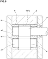
- This proposed gear pump device has, as shown in Figure 6 , a pair of gears (a, a) engaged with each other, a housing c having a gear-housing bore b for housing a pair of the gears (a, a), and a side plate d inserted in the gear-housing bore b.
- a ceramic cylindrical bushing e is disposed in a supporting hole of each side plate d.
- a support-shaft portion a1 of each gear (a) is pivotally supported via the bushing e.
- This device is configured so that a portion of rubber within a pump chamber b1 defined between the side plates d, d is circulated, toward the pump chamber b1, through a gap between an inner peripheral surface of the bushing e and an outer peripheral surface of the support-shaft portion a1.
- the rubber scorch within the gap can be reduced to some degree. But it is not enough, and maintenance is necessary on a regular basis (for example, every two or three months). Further, depending on the kind of the rubber, the rubber scorch is caused early, and the torque which is increased thereby may possibly lead the drive system to fail.
- Patent Document 1 Japanese Patent Application Publication No. H10-131870
- a problem is to provide a gear pump device for rubber extrusion, in which rubber scorch at the support-shaft portion can be prevented for a long term, aiming at prolongation of maintenance intervals and prevention of failure of the drive system caused by the increased torque.
- the present invention is a gear pump device for rubber extrusion, which has a pair of gears engaged with each other, a housing having a gear-housing bore housing a pair of the gears, and a bushing ring inserted in the gear-housing bore at end portions thereof in the axial direction, and which is characterized in that the gear has a gear portion and a shaft portion concentrically extending from the gear portion toward both sides in the axial direction, the bushing ring has a bearing and a sealing means built-in, the bearing rotatably supporting the support-shaft portion, and the sealing means disposed inward of the bearing in the axial direction and sealing between it and the outer peripheral surface of the support-shaft portion, and the sealing means includes a sealing ring which is formed from a rubber elastic body whose cross section is ]-shaped and which has a cylindrical first lip portion contacting with the outer peripheral surface of the support-shaft portion, a cylindrical second lip portion disposed outside thereof in the radial direction, and a side wall portion connecting
- the bushing ring has a ring-shaped bushing base portion concentrically inserted in the gear-housing bore, and the inner peripheral surface of the bushing base portion has a circumferential-groove-shaped bearing-retaining groove accommodating the bearing, and a circumferential-groove-shaped sealing-means-retaining groove accommodating the sealing means and formed inside thereof in the axial direction in succession.
- the sealing means has a ring-shaped holder concentrically inserted in the sealing-means-retaining groove, the inner peripheral surface of the holder is provided in its inside in the axial direction with a circumferential-groove-shaped seal-ring-retaining groove accommodating the seal ring, and an inner end in the axial direction, of the seal-ring-retaining groove opens in the inside surface in the axial direction, of the holder.
- the bushing ring inserted in the gear-housing bore incorporates the bearing rotatably supporting the support-shaft portion of each gear, and the sealing means sealing between it and the outer peripheral surface of the support-shaft portion.
- the sealing ring disposed in the sealing means is formed from the rubber elastic body whose cross section is ]-shaped in which the side wall portion connects between the axially outer end of the first lip portion contacting with the outer peripheral surface of the support-shaft portion, and the axially outer end of the second lip portion disposed radially outside thereof.
- Such seal ring is provided therein with a hole portion which is surrounded by the first and second lip portions and the side wall portion and which opens toward a pump chamber. Therefore, if a portion of the rubber existing in the pump chamber flows into the hole portion, then by the pressure of the rubber, the first lip portion is strongly pressed against the outer peripheral surface of the support-shaft portion, and reliably seals between it and the support-shaft portion. This prevents rubber scorch from occurring at the support-shaft portion for a long term, which makes it possible to prolong the maintenance interval. Moreover, as the support-shaft portion is rotatably supported by the bearing, in cooperation with the sealing ring, the operation with low torque is possible, which make it possible to suppress failure of the drive system.
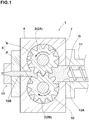
- a gear pump device 1 for rubber extrusion in the present embodiment (hereinafter simply referred to as "gear pump device 1") has a pair of gears 2, 2 engaged with each other, a housing 4 having a gear-housing bore 3 accommodating a pair of the gears 2, 2, and a bushing ring 5 inserted in the gear-housing bore 3.
- the paired gears 2, 2 are, for example, constituted by a driving gear 2A coupled with a motor and, and a driven gear 2B rotated by the gear 2A.
- Each of the gears 2A, 2B has a gear portion 6 with tooth spaces, and a support-shaft portion 7 concentrically extending toward both sides in the axial direction from the gear portion 6.
- the gear-housing bore 3 penetrating therethrough in the axial direction is provided.
- the gear-housing bore 3 has a gourd shape formed by connecting two arcuate portions 8 which are concentric with the respective gears 2A, 2B and, for example, which make sliding contact with the gear portions 6 of the respective gears 2A, 2B.
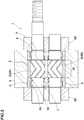
- the region between the bushing rings 5, 5 in the gear-housing bore 3 constitutes a pump chamber 10 (shown in Figure 2 ).
- flow paths 12A, 12B are formed in the housing 4.
- the flow path 12A takes rubber G, for example coming from a rubber extruder 11, into the pump chamber 10.
- the flow path 12B pushes the rubber G out of the pump chamber 10 toward a nozzle 13.
- the flow paths 12A, 12B extend in the direction perpendicular to the axial direction, and communicate with the pump chamber 10 at the connecting position between the arcuate portions 8, 8.
- the bushing rings 5 are inserted in the gear-housing bore 3 at both end portions in the axial direction, respectively.
- the bushing ring 5 incorporates a bearing 15 rotatably supporting the support-shaft portion 7, and a sealing means 16 disposed inside in the axial direction, of the bearing 15.
- the "inside" in the axial direction means the direction toward the center of the axial direction width of the pump chamber 10.
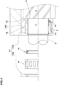
- the bushing ring 5 includes a ring-shaped bushing base portion 17 concentrically inserted in the gear-housing bore 3 (strictly in an arcuate portion 8).
- a circumferential-groove-shaped bearing-retaining groove 18 accommodating the bearing 15, and a circumferential-groove-shaped sealing-means-retaining groove 19 accommodating the sealing means 16 are formed in succession in the axial direction.
- a gap H is formed between the inner peripheral surface of the bushing base portion 17 and the outer peripheral surface of the support-shaft portion 7, a gap H is formed.
- the state before mounting of the bearing 15 and sealing means 16 is shown on the upper side of the axis of the gear 2, and the state after mounting is shown on the lower side of the axis.
- the sealing-means-retaining groove 19 is smaller in diameter than the bearing-retaining groove 18.
- the bushing base portion 17 can be divided into axially inner and outer split pieces 17A, 17B at a position of the outer end in the axial direction, of the bearing-retaining groove 18.
- the sealing means 16 and the bearing 15 can be inserted sequentially and mounted.
- the split pieces 17A, 17B are united with each other by screws or the like.
- a needle bearing can be suitably employed.
- the sealing means 16 seals between it and the outer peripheral surface of the support-shaft portion 7.
- the sealing means 16 in the present embodiment has a holder 20 and a sealing ring 22 formed from a rubber elastic body.
- the holder 20 is ring-shaped, and concentrically inserted in the sealing-means-retaining groove 19.
- the sealing ring 22 is accommodated in a seal-ring-retaining groove 21 which is formed in the inner peripheral surface of the holder 20.
- a circumferential groove 24 for mounting an O-ring 23 sealing between it and the inner peripheral surface of the sealing-means-retaining groove 19.
- the seal-ring-retaining groove 21 is configured in the form of a circumferential groove formed in an inside in the axial direction of the inner peripheral surface of the holder 20.
- the inner end in the axial direction, of the seal-ring-retaining groove 21 is opened in the inside surface in the axial direction, of the holder 20.
- the seal ring 22 has a cylindrical first lip portion 22i contacting with the outer peripheral surface of the support-shaft portion 7, a cylindrical second lip portion 22o disposed outside thereof in the radial direction, and a sidewall portion 22m connecting between outer ends in the axial direction, of the first and second lip portions 22i, 22o so as to have a ]-shaped cross section. Therefore, the sealing ring 22 is provided therein with a hole portion 22H which is surrounded by the first and second lip portions 22i, 22o and the side wall portion 22m and which is opened toward the pump chamber 10.
- the first lip portion 22i is strongly pressed against the outer peripheral surface of the support-shaft portion 7 by the pressure of the rubber G. This can reliably seal between it and the shaft portion 7, and suppress the occurrence of rubber scorch at the support-shaft portion 7 for a long term, which makes it possible to prolong the maintenance interval. Further, as the support-shaft portion 7 is rotatably supported by the bearing 15, in cooperation with the sealing ring 22, the operation at low torque is possible, which make it possible to suppress failure of the drive system.
- the sealing ring 22 it is desirable that it has heat resistance and detachability from unvulcanized rubber, and fluorine-based resins can be employed favorably.
- the fluorine-based resins include
- side plates 25 are attached onto the both sides of the housing 4 to prevent the bushing rings 5 from coming off. While detailed description has been made of an especially preferable embodiment of the present invention, the present invention can be embodied in various forms without being limited to the illustrated embodiment.
Landscapes
- Engineering & Computer Science (AREA)
- Mechanical Engineering (AREA)
- General Engineering & Computer Science (AREA)
- Rotary Pumps (AREA)
- Details And Applications Of Rotary Liquid Pumps (AREA)
Abstract
Description
- The present invention relates to a gear pump device for rubber extrusion capable of preventing rubber scorch from occurring at a support-shaft portion for a long term.
- As a gear pump device for rubber extrusion, for example, there have been proposed one described in the following
Patent Document 1. This proposed gear pump device has, as shown inFigure 6 , a pair of gears (a, a) engaged with each other, a housing c having a gear-housing bore b for housing a pair of the gears (a, a), and a side plate d inserted in the gear-housing bore b.
In a supporting hole of each side plate d, a ceramic cylindrical bushing e is disposed. Then, a support-shaft portion a1 of each gear (a) is pivotally supported via the bushing e. - This device is configured so that a portion of rubber within a pump chamber b1 defined between the side plates d, d is circulated, toward the pump chamber b1, through a gap between an inner peripheral surface of the bushing e and an outer peripheral surface of the support-shaft portion a1. In this case, as the rubber flows in the direction of the circulation within the gap, the rubber scorch within the gap can be reduced to some degree. But it is not enough, and maintenance is necessary on a regular basis (for example, every two or three months).
Further, depending on the kind of the rubber, the rubber scorch is caused early, and the torque which is increased thereby may possibly lead the drive system to fail. - Patent Document 1: Japanese Patent Application Publication No.
H10-131870 - In the present invention, therefore, a problem is to provide a gear pump device for rubber extrusion, in which rubber scorch at the support-shaft portion can be prevented for a long term, aiming at prolongation of maintenance intervals and prevention of failure of the drive system caused by the increased torque.
- The present invention is a gear pump device for rubber extrusion, which has a pair of gears engaged with each other, a housing having a gear-housing bore housing a pair of the gears, and a bushing ring inserted in the gear-housing bore at end portions thereof in the axial direction, and which is characterized in that
the gear has a gear portion and a shaft portion concentrically extending from the gear portion toward both sides in the axial direction,
the bushing ring has a bearing and a sealing means built-in, the bearing rotatably supporting the support-shaft portion, and the sealing means disposed inward of the bearing in the axial direction and sealing between it and the outer peripheral surface of the support-shaft portion, and
the sealing means includes a sealing ring which is formed from a rubber elastic body whose cross section is ]-shaped and which has a cylindrical first lip portion contacting with the outer peripheral surface of the support-shaft portion, a cylindrical second lip portion disposed outside thereof in the radial direction, and a side wall portion connecting between axially outer ends of the first and second lip portions. - In the gear pump device for rubber extrusion according to the present invention, it is preferable that
the bushing ring has a ring-shaped bushing base portion concentrically inserted in the gear-housing bore, and
the inner peripheral surface of the bushing base portion has a circumferential-groove-shaped bearing-retaining groove accommodating the bearing, and a circumferential-groove-shaped sealing-means-retaining groove accommodating the sealing means and formed inside thereof in the axial direction in succession. - In the gear pump device for rubber extrusion according to the present invention, it is preferable that
the sealing means has a ring-shaped holder concentrically inserted in the sealing-means-retaining groove,
the inner peripheral surface of the holder is provided in its inside in the axial direction with a circumferential-groove-shaped seal-ring-retaining groove accommodating the seal ring, and
an inner end in the axial direction, of the seal-ring-retaining groove opens in the inside surface in the axial direction, of the holder. - In the present invention, the bushing ring inserted in the gear-housing bore incorporates the bearing rotatably supporting the support-shaft portion of each gear, and the sealing means sealing between it and the outer peripheral surface of the support-shaft portion. And the sealing ring disposed in the sealing means is formed from the rubber elastic body whose cross section is ]-shaped in which the side wall portion connects between the axially outer end of the first lip portion contacting with the outer peripheral surface of the support-shaft portion, and the axially outer end of the second lip portion disposed radially outside thereof.
- Such seal ring is provided therein with a hole portion which is surrounded by the first and second lip portions and the side wall portion and which opens toward a pump chamber. Therefore, if a portion of the rubber existing in the pump chamber flows into the hole portion, then by the pressure of the rubber, the first lip portion is strongly pressed against the outer peripheral surface of the support-shaft portion, and reliably seals between it and the support-shaft portion. This prevents rubber scorch from occurring at the support-shaft portion for a long term, which makes it possible to prolong the maintenance interval.
Moreover, as the support-shaft portion is rotatably supported by the bearing, in cooperation with the sealing ring, the operation with low torque is possible, which make it possible to suppress failure of the drive system. -
- [
Figure 1 ] A cross-sectional view perpendicular to the axial direction which shows an embodiment of the gear pump device for rubber extrusion of the present invention. - [
Figure 2 ] A cross-sectional view taken along the axial direction of the gear pump device inFigure 1 . - [
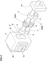
Figure 3 ] An exploded perspective view schematically showing the gear pump device inFigure 1 . - [
Figure 4 ] A cross-sectional view taken along the axial direction which shows the bushing ring. - [
Figure 5 ] A cross-sectional view taken along the axial direction which shows the sealing means. - [
Figure 6 ] A cross-sectional view taken along the axial direction which shows a example of a conventional gear pump device. - Hereinafter, embodiments of the present invention will be described in detail.
- As shown in
Figures 1-3 , agear pump device 1 for rubber extrusion in the present embodiment (hereinafter simply referred to as "gear pump device 1") has a pair ofgears housing 4 having a gear-housing bore 3 accommodating a pair of thegears bushing ring 5 inserted in the gear-housing bore 3. - The paired
gears driving gear 2A coupled with a motor and, and a drivengear 2B rotated by thegear 2A.
Each of thegears gear portion 6 with tooth spaces, and a support-shaft portion 7 concentrically extending toward both sides in the axial direction from thegear portion 6. - Inside the
housing 4, the gear-housing bore 3 penetrating therethrough in the axial direction is provided. The gear-housing bore 3 has a gourd shape formed by connecting twoarcuate portions 8 which are concentric with therespective gears gear portions 6 of therespective gears bushing rings housing bore 3 constitutes a pump chamber 10 (shown inFigure 2 ). - As shown in
Figure 1 ,flow paths housing 4. Theflow path 12A takes rubber G, for example coming from arubber extruder 11, into thepump chamber 10. Theflow path 12B pushes the rubber G out of thepump chamber 10 toward anozzle 13. Theflow paths pump chamber 10 at the connecting position between thearcuate portions - As shown in
Figures 2 and3 , thebushing rings 5 are inserted in the gear-housing bore 3 at both end portions in the axial direction, respectively.
Thebushing ring 5 incorporates a bearing 15 rotatably supporting the support-shaft portion 7, and a sealing means 16 disposed inside in the axial direction, of thebearing 15. Here, the "inside" in the axial direction means the direction toward the center of the axial direction width of thepump chamber 10. - Specifically, as shown in
Figure 4 , thebushing ring 5 includes a ring-shapedbushing base portion 17 concentrically inserted in the gear-housing bore 3 (strictly in an arcuate portion 8).
In the inner peripheral surface of thebushing base portion 17, a circumferential-groove-shaped bearing-retaininggroove 18 accommodating thebearing 15, and
a circumferential-groove-shaped sealing-means-retaininggroove 19 accommodating the sealing means 16
are formed in succession in the axial direction. Between the inner peripheral surface of thebushing base portion 17 and the outer peripheral surface of the support-shaft portion 7, a gap H is formed.
InFigure 4 , the state before mounting of thebearing 15 and sealing means 16 is shown on the upper side of the axis of thegear 2, and the state after mounting is shown on the lower side of the axis. - The sealing-means-retaining
groove 19 is smaller in diameter than the bearing-retaininggroove 18.
Thebushing base portion 17 can be divided into axially inner andouter split pieces groove 18. Thus, from the side of the outer end of thebushing ring 5, the sealing means 16 and thebearing 15 can be inserted sequentially and mounted. Incidentally, thesplit pieces - As the
bearing 15, a needle bearing can be suitably employed. - The sealing means 16 seals between it and the outer peripheral surface of the support-
shaft portion 7. As shown inFigure 5 , the sealing means 16 in the present embodiment has aholder 20 and a sealingring 22 formed from a rubber elastic body.
Theholder 20 is ring-shaped, and concentrically inserted in the sealing-means-retaininggroove 19.
The sealingring 22 is accommodated in a seal-ring-retaininggroove 21 which is formed in the inner peripheral surface of theholder 20.
In the outer peripheral surface of theholder 20, there is formed acircumferential groove 24 for mounting an O-ring 23 sealing between it and the inner peripheral surface of the sealing-means-retaininggroove 19. - The seal-ring-retaining
groove 21 is configured in the form of a circumferential groove formed in an inside in the axial direction of the inner peripheral surface of theholder 20. The inner end in the axial direction, of the seal-ring-retaininggroove 21 is opened in the inside surface in the axial direction, of theholder 20. - The
seal ring 22 has a cylindrical first lip portion 22i contacting with the outer peripheral surface of the support-shaft portion 7, a cylindrical second lip portion 22o disposed outside thereof in the radial direction, and asidewall portion 22m connecting between outer ends in the axial direction, of the first and second lip portions 22i, 22o so as to have a ]-shaped cross section. Therefore, the sealingring 22 is provided therein with ahole portion 22H which is surrounded by the first and second lip portions 22i, 22o and theside wall portion 22m and which is opened toward thepump chamber 10. - Thus, when a portion of the rubber G existing in the
pump chamber 10 flows into thehole portion 22H through the gap H, the first lip portion 22i is strongly pressed against the outer peripheral surface of the support-shaft portion 7 by the pressure of the rubber G. This can reliably seal between it and theshaft portion 7, and suppress the occurrence of rubber scorch at the support-shaft portion 7 for a long term, which makes it possible to prolong the maintenance interval. Further, as the support-shaft portion 7 is rotatably supported by thebearing 15, in cooperation with the sealingring 22, the operation at low torque is possible, which make it possible to suppress failure of the drive system. - As to the sealing
ring 22, it is desirable that it has heat resistance and detachability from unvulcanized rubber, and fluorine-based resins can be employed favorably. The fluorine-based resins include - fully fluorinated resin which is polytetrafluoroethylene (tetrafluorinated resin, abbreviation: PTFE)
- partially fluorinated resins which are polychlorotrifluoroethylene (trifluorinated resins, abbreviations: PCTFE, CTFE), polyvinylidene fluoride (abbreviations: PVDF), polyvinyl fluoride (abbreviation: PVF)
- fluorinated resin copolymers which are perfluoroalkoxy fluorocarbon resin (abbreviation: PFA), tetrafluoroethylene-hexafluoropropylene copolymer (abbreviation: FEP), ethylene tetrafluoroethylene copolymer (abbreviation: ETFE), ethylene-chlorotrifluoroethylene copolymer (abbreviation: ECTFE) and the like.
- Further, side plates 25 (shown in
Figures 2 and3 ) are attached onto the both sides of thehousing 4 to prevent the bushing rings 5 from coming off.
while detailed description has been made of an especially preferable embodiment of the present invention, the present invention can be embodied in various forms without being limited to the illustrated embodiment. -
- 1
- gear pump device for rubber extrusion
- 2, 2A, 2B
- gear
- 3
- gear-housing bore
- 4
- housing
- 5
- bushing ring
- 6
- gear portion
- 7
- support-shaft portion
- 15
- bearing
- 16
- sealing means
- 17
- bushing base portion
- 18
- bearing-retaining groove
- 19
- sealing-means-retaining groove
- 20
- holder
- 21
- seal-ring-retaining groove
- 22
- sealing ring
Claims (3)
- A gear pump device for rubber extrusion,
which has a pair of gears engaged with each other, a housing having a gear-housing bore housing a pair of the gears, and a bushing ring inserted in the gear-housing bore at end portions thereof in the axial direction, and
which is characterized in that
the gear has a gear portion and a shaft portion concentrically extending from the gear portion toward both sides in the axial direction,
the bushing ring has a bearing and a sealing means built-in, the bearing rotatably supporting the support-shaft portion, and the sealing means disposed inward of the bearing in the axial direction and sealing between it and the outer peripheral surface of the support-shaft portion, and
the sealing means includes a sealing ring which is formed from a rubber elastic body whose cross section is ]-shaped and which has a cylindrical first lip portion contacting with the outer peripheral surface of the support-shaft portion, a cylindrical second lip portion disposed outside thereof in the radial direction, and a side wall portion connecting between axially outer ends of the first and second lip portions. - The gear pump device for rubber extrusion as set forth in claim 1, which is characterized in that
the bushing ring has a ring-shaped bushing base portion concentrically inserted in the gear-housing bore, and
the inner peripheral surface of the bushing base portion has a circumferential-groove-shaped bearing-retaining groove accommodating the bearing, and a circumferential-groove-shaped sealing-means-retaining groove accommodating the sealing means and formed inside thereof in the axial direction in succession. - The gear pump device for rubber extrusion as set forth in claim 2, which is characterized in that
the sealing means has a ring-shaped holder concentrically inserted in the sealing-means-retaining groove,
the inner peripheral surface of the holder is provided in its inside in the axial direction with a circumferential-groove-shaped seal-ring-retaining groove accommodating the seal ring, and
an inner end in the axial direction, of the seal-ring-retaining groove opens in the inside surface in the axial direction, of the holder.
Applications Claiming Priority (2)
| Application Number | Priority Date | Filing Date | Title |
|---|---|---|---|
| JP2015217795A JP6616663B2 (en) | 2015-11-05 | 2015-11-05 | Gear pump equipment for rubber extrusion |
| PCT/JP2016/079227 WO2017077798A1 (en) | 2015-11-05 | 2016-10-03 | Gear pump device for rubber extrusion |
Publications (3)
| Publication Number | Publication Date |
|---|---|
| EP3364034A1 true EP3364034A1 (en) | 2018-08-22 |
| EP3364034A4 EP3364034A4 (en) | 2019-06-26 |
| EP3364034B1 EP3364034B1 (en) | 2023-05-10 |
Family
ID=58661821
Family Applications (1)
| Application Number | Title | Priority Date | Filing Date |
|---|---|---|---|
| EP16861866.8A Active EP3364034B1 (en) | 2015-11-05 | 2016-10-03 | Gear pump device for rubber extrusion |
Country Status (5)
| Country | Link |
|---|---|
| US (1) | US10738776B2 (en) |
| EP (1) | EP3364034B1 (en) |
| JP (1) | JP6616663B2 (en) |
| CN (1) | CN108350877B (en) |
| WO (1) | WO2017077798A1 (en) |
Cited By (2)
| Publication number | Priority date | Publication date | Assignee | Title |
|---|---|---|---|---|
| FR3091317A1 (en) * | 2018-12-26 | 2020-07-03 | Poclain Hydraulics Industrie | Hydraulic pump, cover and flange intended to equip such a pump |
| US12247617B2 (en) | 2022-12-08 | 2025-03-11 | Hamilton Sundstrand Corporation | Cavitation resistant journal bearing |
Family Cites Families (11)
| Publication number | Priority date | Publication date | Assignee | Title |
|---|---|---|---|---|
| FR1526323A (en) * | 1967-04-14 | 1968-05-24 | Sigma | Improvements to hydraulic gear pumps and motors |
| JPS512Y1 (en) * | 1968-09-16 | 1976-01-06 | ||
| JPS53109205A (en) * | 1977-03-05 | 1978-09-22 | Hitachi Maxell Ltd | Gear pump |
| JP3602275B2 (en) | 1996-10-29 | 2004-12-15 | 光洋精工株式会社 | Gear pump |
| US7419165B2 (en) * | 2004-08-18 | 2008-09-02 | Federal-Mogul World Wide, Inc. | Seal assembly and method of manufacturing the same |
| ES2349495T3 (en) * | 2007-05-03 | 2011-01-04 | OERLIKON TEXTILE GMBH & CO. KG | GEAR PUMP. |
| CN201212474Y (en) * | 2008-07-31 | 2009-03-25 | 哈尔滨理工大学 | A high viscosity polymer melt pump |
| US8821140B2 (en) * | 2010-04-29 | 2014-09-02 | Dan Paval | Gear pump |
| JP2012076550A (en) * | 2010-09-30 | 2012-04-19 | Advics Co Ltd | Plunger type master cylinder |
| US8998496B2 (en) | 2012-03-30 | 2015-04-07 | Imo Industries, Inc. | Gear pump with asymmetrical dual bearing |
| CN104265903B (en) * | 2014-09-29 | 2017-04-12 | 太仓正信干燥设备科技有限公司 | Component sealing structure of crushing knife of double cone dryer |
-
2015
- 2015-11-05 JP JP2015217795A patent/JP6616663B2/en active Active
-
2016
- 2016-10-03 EP EP16861866.8A patent/EP3364034B1/en active Active
- 2016-10-03 US US15/770,639 patent/US10738776B2/en active Active
- 2016-10-03 WO PCT/JP2016/079227 patent/WO2017077798A1/en not_active Ceased
- 2016-10-03 CN CN201680060763.2A patent/CN108350877B/en active Active
Cited By (2)
| Publication number | Priority date | Publication date | Assignee | Title |
|---|---|---|---|---|
| FR3091317A1 (en) * | 2018-12-26 | 2020-07-03 | Poclain Hydraulics Industrie | Hydraulic pump, cover and flange intended to equip such a pump |
| US12247617B2 (en) | 2022-12-08 | 2025-03-11 | Hamilton Sundstrand Corporation | Cavitation resistant journal bearing |
Also Published As
| Publication number | Publication date |
|---|---|
| US10738776B2 (en) | 2020-08-11 |
| US20180320686A1 (en) | 2018-11-08 |
| EP3364034B1 (en) | 2023-05-10 |
| JP2017089434A (en) | 2017-05-25 |
| JP6616663B2 (en) | 2019-12-04 |
| CN108350877B (en) | 2021-04-20 |
| WO2017077798A1 (en) | 2017-05-11 |
| EP3364034A4 (en) | 2019-06-26 |
| CN108350877A (en) | 2018-07-31 |
Similar Documents
| Publication | Publication Date | Title |
|---|---|---|
| US11608896B2 (en) | Multiple component seal assembly | |
| CN106151474B (en) | Dry shaft assembly | |
| US9856984B2 (en) | Sealing device | |
| JP2011058635A (en) | Unitizing element and seal assembling method | |
| US11028925B2 (en) | Seal ring | |
| WO2015108107A1 (en) | Mechanical seal | |
| WO2010103993A1 (en) | Uniaxial eccentric screw pump | |
| EP3364034B1 (en) | Gear pump device for rubber extrusion | |
| US20170299063A1 (en) | Seal device | |
| US8328201B2 (en) | Pumping seal assembly with angled spring | |
| CN107461394B (en) | Temperature Controlled Spindle Assembly with Fluid Inlet Hose | |
| US10344842B2 (en) | Multi-piece sealing assembly | |
| JP6513558B2 (en) | Sealed structure | |
| KR102634783B1 (en) | A vacuum pump having screw rotor | |
| CN1547649A (en) | Seal and Bearing Assemblies | |
| JP2016217290A (en) | Gear pump | |
| US8267406B2 (en) | Retaining ring for a seal ring of a mechanical seal assembly | |
| JP2015183790A (en) | mechanical seal | |
| EP3077709B1 (en) | Rotor shaft seal assembly | |
| JP5356867B2 (en) | Uniaxial eccentric screw pump | |
| EP1637782A1 (en) | Seal housing for a mechanical seal | |
| EP2375073A1 (en) | Sealing for the control chamber of a variable displacement lubricant pump | |
| KR20230145486A (en) | sealing device | |
| US20200400235A1 (en) | Seal device | |
| JP2000227112A (en) | Bearing |
Legal Events
| Date | Code | Title | Description |
|---|---|---|---|
| STAA | Information on the status of an ep patent application or granted ep patent |
Free format text: STATUS: THE INTERNATIONAL PUBLICATION HAS BEEN MADE |
|
| PUAI | Public reference made under article 153(3) epc to a published international application that has entered the european phase |
Free format text: ORIGINAL CODE: 0009012 |
|
| STAA | Information on the status of an ep patent application or granted ep patent |
Free format text: STATUS: REQUEST FOR EXAMINATION WAS MADE |
|
| 17P | Request for examination filed |
Effective date: 20180517 |
|
| AK | Designated contracting states |
Kind code of ref document: A1 Designated state(s): AL AT BE BG CH CY CZ DE DK EE ES FI FR GB GR HR HU IE IS IT LI LT LU LV MC MK MT NL NO PL PT RO RS SE SI SK SM TR |
|
| AX | Request for extension of the european patent |
Extension state: BA ME |
|
| DAV | Request for validation of the european patent (deleted) | ||
| DAX | Request for extension of the european patent (deleted) | ||
| A4 | Supplementary search report drawn up and despatched |
Effective date: 20190527 |
|
| RIC1 | Information provided on ipc code assigned before grant |
Ipc: F04C 15/00 20060101ALI20190521BHEP Ipc: F04C 13/00 20060101ALI20190521BHEP Ipc: F04C 2/16 20060101ALI20190521BHEP Ipc: F04C 2/18 20060101AFI20190521BHEP Ipc: F01C 19/00 20060101ALI20190521BHEP |
|
| STAA | Information on the status of an ep patent application or granted ep patent |
Free format text: STATUS: EXAMINATION IS IN PROGRESS |
|
| 17Q | First examination report despatched |
Effective date: 20220307 |
|
| GRAP | Despatch of communication of intention to grant a patent |
Free format text: ORIGINAL CODE: EPIDOSNIGR1 |
|
| STAA | Information on the status of an ep patent application or granted ep patent |
Free format text: STATUS: GRANT OF PATENT IS INTENDED |
|
| INTG | Intention to grant announced |
Effective date: 20230105 |
|
| GRAS | Grant fee paid |
Free format text: ORIGINAL CODE: EPIDOSNIGR3 |
|
| GRAA | (expected) grant |
Free format text: ORIGINAL CODE: 0009210 |
|
| STAA | Information on the status of an ep patent application or granted ep patent |
Free format text: STATUS: THE PATENT HAS BEEN GRANTED |
|
| AK | Designated contracting states |
Kind code of ref document: B1 Designated state(s): AL AT BE BG CH CY CZ DE DK EE ES FI FR GB GR HR HU IE IS IT LI LT LU LV MC MK MT NL NO PL PT RO RS SE SI SK SM TR |
|
| REG | Reference to a national code |
Ref country code: GB Ref legal event code: FG4D |
|
| REG | Reference to a national code |
Ref country code: AT Ref legal event code: REF Ref document number: 1566914 Country of ref document: AT Kind code of ref document: T Effective date: 20230515 Ref country code: CH Ref legal event code: EP |
|
| REG | Reference to a national code |
Ref country code: DE Ref legal event code: R096 Ref document number: 602016079406 Country of ref document: DE |
|
| REG | Reference to a national code |
Ref country code: IE Ref legal event code: FG4D |
|
| P01 | Opt-out of the competence of the unified patent court (upc) registered |
Effective date: 20230510 |
|
| REG | Reference to a national code |
Ref country code: LT Ref legal event code: MG9D |
|
| REG | Reference to a national code |
Ref country code: NL Ref legal event code: MP Effective date: 20230510 |
|
| REG | Reference to a national code |
Ref country code: AT Ref legal event code: MK05 Ref document number: 1566914 Country of ref document: AT Kind code of ref document: T Effective date: 20230510 |
|
| PG25 | Lapsed in a contracting state [announced via postgrant information from national office to epo] |
Ref country code: SE Free format text: LAPSE BECAUSE OF FAILURE TO SUBMIT A TRANSLATION OF THE DESCRIPTION OR TO PAY THE FEE WITHIN THE PRESCRIBED TIME-LIMIT Effective date: 20230510 Ref country code: PT Free format text: LAPSE BECAUSE OF FAILURE TO SUBMIT A TRANSLATION OF THE DESCRIPTION OR TO PAY THE FEE WITHIN THE PRESCRIBED TIME-LIMIT Effective date: 20230911 Ref country code: NO Free format text: LAPSE BECAUSE OF FAILURE TO SUBMIT A TRANSLATION OF THE DESCRIPTION OR TO PAY THE FEE WITHIN THE PRESCRIBED TIME-LIMIT Effective date: 20230810 Ref country code: NL Free format text: LAPSE BECAUSE OF FAILURE TO SUBMIT A TRANSLATION OF THE DESCRIPTION OR TO PAY THE FEE WITHIN THE PRESCRIBED TIME-LIMIT Effective date: 20230510 Ref country code: ES Free format text: LAPSE BECAUSE OF FAILURE TO SUBMIT A TRANSLATION OF THE DESCRIPTION OR TO PAY THE FEE WITHIN THE PRESCRIBED TIME-LIMIT Effective date: 20230510 Ref country code: AT Free format text: LAPSE BECAUSE OF FAILURE TO SUBMIT A TRANSLATION OF THE DESCRIPTION OR TO PAY THE FEE WITHIN THE PRESCRIBED TIME-LIMIT Effective date: 20230510 |
|
| PG25 | Lapsed in a contracting state [announced via postgrant information from national office to epo] |
Ref country code: RS Free format text: LAPSE BECAUSE OF FAILURE TO SUBMIT A TRANSLATION OF THE DESCRIPTION OR TO PAY THE FEE WITHIN THE PRESCRIBED TIME-LIMIT Effective date: 20230510 Ref country code: PL Free format text: LAPSE BECAUSE OF FAILURE TO SUBMIT A TRANSLATION OF THE DESCRIPTION OR TO PAY THE FEE WITHIN THE PRESCRIBED TIME-LIMIT Effective date: 20230510 Ref country code: LV Free format text: LAPSE BECAUSE OF FAILURE TO SUBMIT A TRANSLATION OF THE DESCRIPTION OR TO PAY THE FEE WITHIN THE PRESCRIBED TIME-LIMIT Effective date: 20230510 Ref country code: LT Free format text: LAPSE BECAUSE OF FAILURE TO SUBMIT A TRANSLATION OF THE DESCRIPTION OR TO PAY THE FEE WITHIN THE PRESCRIBED TIME-LIMIT Effective date: 20230510 Ref country code: IS Free format text: LAPSE BECAUSE OF FAILURE TO SUBMIT A TRANSLATION OF THE DESCRIPTION OR TO PAY THE FEE WITHIN THE PRESCRIBED TIME-LIMIT Effective date: 20230910 Ref country code: HR Free format text: LAPSE BECAUSE OF FAILURE TO SUBMIT A TRANSLATION OF THE DESCRIPTION OR TO PAY THE FEE WITHIN THE PRESCRIBED TIME-LIMIT Effective date: 20230510 Ref country code: GR Free format text: LAPSE BECAUSE OF FAILURE TO SUBMIT A TRANSLATION OF THE DESCRIPTION OR TO PAY THE FEE WITHIN THE PRESCRIBED TIME-LIMIT Effective date: 20230811 |
|
| PG25 | Lapsed in a contracting state [announced via postgrant information from national office to epo] |
Ref country code: FI Free format text: LAPSE BECAUSE OF FAILURE TO SUBMIT A TRANSLATION OF THE DESCRIPTION OR TO PAY THE FEE WITHIN THE PRESCRIBED TIME-LIMIT Effective date: 20230510 |
|
| PG25 | Lapsed in a contracting state [announced via postgrant information from national office to epo] |
Ref country code: SK Free format text: LAPSE BECAUSE OF FAILURE TO SUBMIT A TRANSLATION OF THE DESCRIPTION OR TO PAY THE FEE WITHIN THE PRESCRIBED TIME-LIMIT Effective date: 20230510 |
|
| PG25 | Lapsed in a contracting state [announced via postgrant information from national office to epo] |
Ref country code: SM Free format text: LAPSE BECAUSE OF FAILURE TO SUBMIT A TRANSLATION OF THE DESCRIPTION OR TO PAY THE FEE WITHIN THE PRESCRIBED TIME-LIMIT Effective date: 20230510 Ref country code: SK Free format text: LAPSE BECAUSE OF FAILURE TO SUBMIT A TRANSLATION OF THE DESCRIPTION OR TO PAY THE FEE WITHIN THE PRESCRIBED TIME-LIMIT Effective date: 20230510 Ref country code: RO Free format text: LAPSE BECAUSE OF FAILURE TO SUBMIT A TRANSLATION OF THE DESCRIPTION OR TO PAY THE FEE WITHIN THE PRESCRIBED TIME-LIMIT Effective date: 20230510 Ref country code: EE Free format text: LAPSE BECAUSE OF FAILURE TO SUBMIT A TRANSLATION OF THE DESCRIPTION OR TO PAY THE FEE WITHIN THE PRESCRIBED TIME-LIMIT Effective date: 20230510 Ref country code: DK Free format text: LAPSE BECAUSE OF FAILURE TO SUBMIT A TRANSLATION OF THE DESCRIPTION OR TO PAY THE FEE WITHIN THE PRESCRIBED TIME-LIMIT Effective date: 20230510 Ref country code: CZ Free format text: LAPSE BECAUSE OF FAILURE TO SUBMIT A TRANSLATION OF THE DESCRIPTION OR TO PAY THE FEE WITHIN THE PRESCRIBED TIME-LIMIT Effective date: 20230510 |
|
| REG | Reference to a national code |
Ref country code: DE Ref legal event code: R097 Ref document number: 602016079406 Country of ref document: DE |
|
| PLBE | No opposition filed within time limit |
Free format text: ORIGINAL CODE: 0009261 |
|
| STAA | Information on the status of an ep patent application or granted ep patent |
Free format text: STATUS: NO OPPOSITION FILED WITHIN TIME LIMIT |
|
| 26N | No opposition filed |
Effective date: 20240213 |
|
| PG25 | Lapsed in a contracting state [announced via postgrant information from national office to epo] |
Ref country code: SI Free format text: LAPSE BECAUSE OF FAILURE TO SUBMIT A TRANSLATION OF THE DESCRIPTION OR TO PAY THE FEE WITHIN THE PRESCRIBED TIME-LIMIT Effective date: 20230510 |
|
| PG25 | Lapsed in a contracting state [announced via postgrant information from national office to epo] |
Ref country code: SI Free format text: LAPSE BECAUSE OF FAILURE TO SUBMIT A TRANSLATION OF THE DESCRIPTION OR TO PAY THE FEE WITHIN THE PRESCRIBED TIME-LIMIT Effective date: 20230510 Ref country code: IT Free format text: LAPSE BECAUSE OF FAILURE TO SUBMIT A TRANSLATION OF THE DESCRIPTION OR TO PAY THE FEE WITHIN THE PRESCRIBED TIME-LIMIT Effective date: 20230510 Ref country code: MC Free format text: LAPSE BECAUSE OF FAILURE TO SUBMIT A TRANSLATION OF THE DESCRIPTION OR TO PAY THE FEE WITHIN THE PRESCRIBED TIME-LIMIT Effective date: 20230510 |
|
| REG | Reference to a national code |
Ref country code: CH Ref legal event code: PL |
|
| REG | Reference to a national code |
Ref country code: BE Ref legal event code: MM Effective date: 20231031 |
|
| PG25 | Lapsed in a contracting state [announced via postgrant information from national office to epo] |
Ref country code: LU Free format text: LAPSE BECAUSE OF NON-PAYMENT OF DUE FEES Effective date: 20231003 |
|
| GBPC | Gb: european patent ceased through non-payment of renewal fee |
Effective date: 20231003 |
|
| PG25 | Lapsed in a contracting state [announced via postgrant information from national office to epo] |
Ref country code: LU Free format text: LAPSE BECAUSE OF NON-PAYMENT OF DUE FEES Effective date: 20231003 |
|
| PG25 | Lapsed in a contracting state [announced via postgrant information from national office to epo] |
Ref country code: GB Free format text: LAPSE BECAUSE OF NON-PAYMENT OF DUE FEES Effective date: 20231003 |
|
| PG25 | Lapsed in a contracting state [announced via postgrant information from national office to epo] |
Ref country code: CH Free format text: LAPSE BECAUSE OF NON-PAYMENT OF DUE FEES Effective date: 20231031 |
|
| PG25 | Lapsed in a contracting state [announced via postgrant information from national office to epo] |
Ref country code: GB Free format text: LAPSE BECAUSE OF NON-PAYMENT OF DUE FEES Effective date: 20231003 Ref country code: CH Free format text: LAPSE BECAUSE OF NON-PAYMENT OF DUE FEES Effective date: 20231031 |
|
| PG25 | Lapsed in a contracting state [announced via postgrant information from national office to epo] |
Ref country code: BE Free format text: LAPSE BECAUSE OF NON-PAYMENT OF DUE FEES Effective date: 20231031 |
|
| PG25 | Lapsed in a contracting state [announced via postgrant information from national office to epo] |
Ref country code: IE Free format text: LAPSE BECAUSE OF NON-PAYMENT OF DUE FEES Effective date: 20231003 |
|
| PG25 | Lapsed in a contracting state [announced via postgrant information from national office to epo] |
Ref country code: IE Free format text: LAPSE BECAUSE OF NON-PAYMENT OF DUE FEES Effective date: 20231003 |
|
| PG25 | Lapsed in a contracting state [announced via postgrant information from national office to epo] |
Ref country code: BG Free format text: LAPSE BECAUSE OF FAILURE TO SUBMIT A TRANSLATION OF THE DESCRIPTION OR TO PAY THE FEE WITHIN THE PRESCRIBED TIME-LIMIT Effective date: 20230510 |
|
| PG25 | Lapsed in a contracting state [announced via postgrant information from national office to epo] |
Ref country code: BG Free format text: LAPSE BECAUSE OF FAILURE TO SUBMIT A TRANSLATION OF THE DESCRIPTION OR TO PAY THE FEE WITHIN THE PRESCRIBED TIME-LIMIT Effective date: 20230510 |
|
| PG25 | Lapsed in a contracting state [announced via postgrant information from national office to epo] |
Ref country code: CY Free format text: LAPSE BECAUSE OF FAILURE TO SUBMIT A TRANSLATION OF THE DESCRIPTION OR TO PAY THE FEE WITHIN THE PRESCRIBED TIME-LIMIT; INVALID AB INITIO Effective date: 20161003 |
|
| PG25 | Lapsed in a contracting state [announced via postgrant information from national office to epo] |
Ref country code: HU Free format text: LAPSE BECAUSE OF FAILURE TO SUBMIT A TRANSLATION OF THE DESCRIPTION OR TO PAY THE FEE WITHIN THE PRESCRIBED TIME-LIMIT; INVALID AB INITIO Effective date: 20161003 |
|
| PG25 | Lapsed in a contracting state [announced via postgrant information from national office to epo] |
Ref country code: TR Free format text: LAPSE BECAUSE OF FAILURE TO SUBMIT A TRANSLATION OF THE DESCRIPTION OR TO PAY THE FEE WITHIN THE PRESCRIBED TIME-LIMIT Effective date: 20230510 |
|
| PGFP | Annual fee paid to national office [announced via postgrant information from national office to epo] |
Ref country code: FR Payment date: 20251030 Year of fee payment: 10 |
|
| PGFP | Annual fee paid to national office [announced via postgrant information from national office to epo] |
Ref country code: DE Payment date: 20251229 Year of fee payment: 10 |