EP3364027A1 - Drainage pump assembly - Google Patents
Drainage pump assembly Download PDFInfo
- Publication number
- EP3364027A1 EP3364027A1 EP17156823.1A EP17156823A EP3364027A1 EP 3364027 A1 EP3364027 A1 EP 3364027A1 EP 17156823 A EP17156823 A EP 17156823A EP 3364027 A1 EP3364027 A1 EP 3364027A1
- Authority
- EP
- European Patent Office
- Prior art keywords
- drainage pump
- sedimentation trap
- pump assembly
- assembly according
- outlet
- Prior art date
- Legal status (The legal status is an assumption and is not a legal conclusion. Google has not performed a legal analysis and makes no representation as to the accuracy of the status listed.)
- Granted
Links
Images


Classifications
-
- F—MECHANICAL ENGINEERING; LIGHTING; HEATING; WEAPONS; BLASTING
- F04—POSITIVE - DISPLACEMENT MACHINES FOR LIQUIDS; PUMPS FOR LIQUIDS OR ELASTIC FLUIDS
- F04B—POSITIVE-DISPLACEMENT MACHINES FOR LIQUIDS; PUMPS
- F04B15/00—Pumps adapted to handle specific fluids, e.g. by selection of specific materials for pumps or pump parts
- F04B15/02—Pumps adapted to handle specific fluids, e.g. by selection of specific materials for pumps or pump parts the fluids being viscous or non-homogeneous
-
- B—PERFORMING OPERATIONS; TRANSPORTING
- B01—PHYSICAL OR CHEMICAL PROCESSES OR APPARATUS IN GENERAL
- B01D—SEPARATION
- B01D21/00—Separation of suspended solid particles from liquids by sedimentation
- B01D21/26—Separation of sediment aided by centrifugal force or centripetal force
- B01D21/265—Separation of sediment aided by centrifugal force or centripetal force by using a vortex inducer or vortex guide, e.g. coil
-
- B—PERFORMING OPERATIONS; TRANSPORTING
- B01—PHYSICAL OR CHEMICAL PROCESSES OR APPARATUS IN GENERAL
- B01D—SEPARATION
- B01D21/00—Separation of suspended solid particles from liquids by sedimentation
- B01D21/26—Separation of sediment aided by centrifugal force or centripetal force
- B01D21/267—Separation of sediment aided by centrifugal force or centripetal force by using a cyclone
-
- F—MECHANICAL ENGINEERING; LIGHTING; HEATING; WEAPONS; BLASTING
- F04—POSITIVE - DISPLACEMENT MACHINES FOR LIQUIDS; PUMPS FOR LIQUIDS OR ELASTIC FLUIDS
- F04B—POSITIVE-DISPLACEMENT MACHINES FOR LIQUIDS; PUMPS
- F04B47/00—Pumps or pumping installations specially adapted for raising fluids from great depths, e.g. well pumps
- F04B47/005—Sand trap arrangements
-
- F—MECHANICAL ENGINEERING; LIGHTING; HEATING; WEAPONS; BLASTING
- F04—POSITIVE - DISPLACEMENT MACHINES FOR LIQUIDS; PUMPS FOR LIQUIDS OR ELASTIC FLUIDS
- F04B—POSITIVE-DISPLACEMENT MACHINES FOR LIQUIDS; PUMPS
- F04B53/00—Component parts, details or accessories not provided for in, or of interest apart from, groups F04B1/00 - F04B23/00 or F04B39/00 - F04B47/00
- F04B53/20—Filtering
-
- F—MECHANICAL ENGINEERING; LIGHTING; HEATING; WEAPONS; BLASTING
- F04—POSITIVE - DISPLACEMENT MACHINES FOR LIQUIDS; PUMPS FOR LIQUIDS OR ELASTIC FLUIDS
- F04B—POSITIVE-DISPLACEMENT MACHINES FOR LIQUIDS; PUMPS
- F04B53/00—Component parts, details or accessories not provided for in, or of interest apart from, groups F04B1/00 - F04B23/00 or F04B39/00 - F04B47/00
- F04B53/10—Valves; Arrangement of valves
- F04B53/12—Valves; Arrangement of valves arranged in or on pistons
- F04B53/125—Reciprocating valves
- F04B53/127—Disc valves
-
- F—MECHANICAL ENGINEERING; LIGHTING; HEATING; WEAPONS; BLASTING
- F04—POSITIVE - DISPLACEMENT MACHINES FOR LIQUIDS; PUMPS FOR LIQUIDS OR ELASTIC FLUIDS
- F04B—POSITIVE-DISPLACEMENT MACHINES FOR LIQUIDS; PUMPS
- F04B53/00—Component parts, details or accessories not provided for in, or of interest apart from, groups F04B1/00 - F04B23/00 or F04B39/00 - F04B47/00
- F04B53/22—Arrangements for enabling ready assembly or disassembly
Definitions
- the present invention relates generally to the field of pumps configured to pump liquid comprising solid matter. Further, the present invention relates specifically to the field of drainage pump assemblies especially configured for pumping liquid comprising sand and stone material, such as drilling water in mining applications or surface water on construction sites.
- the drainage pump assembly comprises a drainage pump and an outlet conduit connected to said drainage pump, the drainage pump comprising a pump chamber.
- each step/lift may for instance be in the range 25-50 meters in the vertical direction, and the length of the outlet conduit, i.e. the transport distance, in each step/lift may for instance be in the range 100-300 meters.
- the drainage pumps are in constant operation, irrespective of water being pumped or not. Constant operation of the drainage pump may damage the drainage pump and result in excessive energy consumption.
- the drainage pump is therefore stopped when the water level in the specific basin housing the drainage pump is low, for instance the drainage pump is stopped when the drainage pump is snoring.
- the drainage pump is snoring when a mixture of air and water is sucked into the drainage pump.
- all liquid that is present in the outlet conduit for instance 100-200 liters
- the drainage pump Due to the high content of sand also a considerable amount of sand will rush back (for instance 10-20 liters).
- the drainage pump is stopped to decrease the use of energy when the drainage pump is not able to lift any liquid, i.e. snoring.
- a great disadvantage is that both the water and sand has to be pumped several times also resulting in increased wear on the drainage pump.
- a non-return valve cannot be arranged downstream the drainage pump.
- a non-return valve will stop the water from rushing back towards the drainage pump, however the sand will slide back through the outlet conduit and block/damage the non-return valve since the sand will settle on top of the non-return valve and thereby prevent subsequent opening.
- the present invention aims at obviating the aforementioned disadvantages and failings of previously known drainage pumps assemblies, and at providing an improved drainage pump assembly.
- a primary object of the present invention is to provide an improved drainage pump assembly of the initially defined type that allows the drainage pump to be stopped without having to pump the liquid comprising solid matter several times. It is another object of the present invention to provide a drainage pump assembly that allows the drainage pump to be stopped without running the risk of being blocked by the solid matter comprised in the pumped liquid.
- a drainage pump assembly of the initially defined type which is characterized in that the outlet conduit comprises a sedimentation trap having an inlet opening, an outlet opening and a belly located between said inlet opening and said outlet opening, and comprises a first conduit extending between the pump chamber of the pump and the belly of the sedimentation trap, wherein said first conduit comprises a non-return valve and wherein the outlet opening of the sedimentation trap is configured to be connected to a second conduit.
- the present invention is based on the insight of having a sedimentation trap configured to house all solid matter sliding back towards the drainage pump when the non-return valve is closed, for instance when the drainage pump is stopped/deactivated, and thereby protecting the non-return located between the drainage pump and the sedimentation trap.
- the belly of the sedimentation trap has a belly volume V [dm 3 ] that is equal to a factor X [dm] times the cross sectional area A [dm 2 ] of the outlet opening of the sedimentation trap, wherein the factor X is equal to or greater than 2, and equal to or less than 12.
- a centre axis of the inlet opening of the sedimentation trap has a negative slope. Therefore the solid matter is prevented from sliding backwards from the sedimentation trap towards the drainage pump, even though the drainage pump should be located at a lower level than the sedimentation trap.
- the non-return valve is constituted by a flap valve, and preferably the valve member of the non-return valve is biased towards an open position.
- the non-return valve has minimal or no negative effect on the pumped liquid flow when the drainage pump is active and pumps liquid through the sedimentation trap.
- the present invention relates specifically to the field of drainage pump assemblies especially configured for pumping liquid comprising solid matter, such as sand and stone material.
- the drainage pump assembly 1 comprises a drainage pump 2 and an outlet conduit, generally designated 3.
- the disclosed drainage pump 2 comprises an inlet 4, a pump housing 5 and a pump outlet 6.
- the drainage pump 2 comprises in a conventional way a hydraulic unit having a pump chamber (not disclosed), and comprises a drive unit (not disclosed).
- the drive unit and the pump chamber are arranged in the pump housing 5.
- the drive unit comprises an electrical motor arranged in the liquid tight pump housing 5, and a drive shaft extending from the electrical motor.
- An impeller (not disclosed) is arranged in the pump chamber and is driven in rotation by the drive shaft during operation of the drainage pump 2, wherein liquid is sucked into said inlet 4 and pumped out of said outlet 6 when the drainage pump 2 is active.
- the pump housing 5 and the impeller, and other essential components, are preferably made of metal.
- the electrical motor is powered via an electrical cable extending from a power supply
- the drainage pump 2 comprises a liquid tight lead-through receiving the electrical cable.
- the drive unit comprises an internal combustion engine and a suitable gear box arrangement, wherein the drive shaft is driven in rotation by the internal combustion engine via said gear box arrangement. Drainage pump arrangements comprising internal combustion engines are conventionally used in dry installations, i.e. the entire pump is then located above the liquid surface and an inlet pipe extend from the pump inlet into the liquid.
- the drainage pump 2 may also comprise a control unit, such as an Intelligent Drive or Variable Frequency Drive (VFD), located inside the liquid tight pump housing 4.
- the control unit is configured to control the operational speed of the drainage pump 2.
- the components of the drainage pump 2 are usually cold down by means of the liquid surrounding the drainage pump 2.
- the drainage pump 2 is designed and configured to be able to operate in a submerged configuration/position, i.e. during operation be located entirely under the liquid surface. However, it shall be realized that the submersible drainage pump 2 during operation must not be entirely located under the liquid surface but may continuously or occasionally be partly located above the liquid surface.
- the drainage pump 2 is in the disclosed application located in a first/lower basin 7 and is intended to transport/pump liquid comprising solid matter from said first/lower basin 7 to a second/higher basin 8. Thereto, it shall be realized that it is conceivable that another drainage pump is located in the second basin 8 and intended to transport the liquid from the second basin 8 to a third basin, etc.
- the basins may be natural recesses/cavities/pits or prepared recesses/cavities/pits.
- FIG. 1 discloses a first embodiment of a sedimentation trap.
- the outlet conduit 3 comprises a sedimentation trap, generally designated 9, and a first conduit 10.
- the sedimentation trap 9 has an inlet opening 11, an outlet opening 12 and a belly 13 located between said inlet opening 11 and said outlet opening 12.
- the first conduit 10 extends between the pump chamber of the drainage pump 2 and the belly 13 of the sedimentation trap 9. Thereto, said first conduit 10 comprises a non-return valve, generally designated 14.
- the belly 13 is a structural formation arranged in such a way that liquid will become stagnant in the belly 13 and solid matter will settle in the belly 13 when the drainage pump 2 is not pumping liquid and the non-return valve 14 is closed. Thus, the belly 13 bulges in relation to the inlet opening 11 and the outlet opening 12.
- the belly 13 may also be denominated a sump, an interior cavity, a sink, a reservoir, i.e. a structural formation that is used to temporarily store/accumulate solid matter.
- the outlet opening 12 of the sedimentation trap 9 is configured to be connected to a second conduit 15, wherein the second conduit 15 is configured to transport the pumped liquid to said second basin 8.
- the non-return valve 14 is preferably arranged at the inlet opening 11 of the sedimentation trap 9. Another feasible location of the non-return valve is at the outlet opening 6 of the drainage pump 2.
- the non-return valve 14 is constituted by a flap valve and is connected to the inlet opening 11 of the sedimentation trap 9, wherein a valve disc 16 of the flap valve is located in or facing the belly 13 and a valve seat 17 of the flap valve is facing the belly 13.
- the valve seat 17 comprises a rim 17' arranged to engage the valve disc 16 when the non-return valve is closed.
- the valve disc 16 and the valve seat 17 are preferably made of metal.
- the valve disc 16 is connected to the valve seat 17 via a hinge member 18.
- the hinge member 18 is preferably made of rubber, preferably vulcanized to the valve disc 16 and valve seat 17, respectively. It is also feasible to use an adhesive to attach the hinge member 18 to the valve disc 16 and valve seat 17, respectively.
- the valve disc 16 (or valve member) is preferably biased towards an open position. When the pump is deactivated the liquid in the outlet conduit will force the non-return valve 14 to close.
- a centre axis of the inlet opening 11 of the sedimentation trap 9 has a negative slope. Said centre axis extends perpendicular to the cross section area of the inlet opening 11. The term negative slope is defined in view of the flow direction of the pumped liquid when the drainage pump2 is active.
- a centre axis of the outlet opening 12 of the sedimentation trap 9 has a positive slope. Said centre axis extends perpendicular to the cross section area of the outlet opening 12.
- the term positive slope is defined in view of the flow direction of the pumped liquid when the drainage pump2 is active.
- the diameter of the cross section area of the outlet opening 12 is preferably in the range 75-125 millimeters, however both smaller and larger diameters are conceivable.
- an inlet pipe fitting 19 is connected to the inlet opening 11 of the sedimentation trap 9.
- the inlet pipe fitting 19 comprises an inlet opening 20, wherein a centre axis of the inlet opening 20 of the inlet pipe fitting 19 preferably extends in the vertical direction.
- an outlet pipe fitting 21 is connected to the outlet opening 12 of the sedimentation trap 9.
- the outlet pipe fitting 21 comprises an outlet opening 22, wherein a centre axis of the outlet opening 22 of the outlet pipe fitting 21 extends in the vertical direction.
- the term vertical is defined having the sedimentation trap 9 standing in an operational position on a horizontal surface.
- the centre axis of the inlet opening 20 of the inlet pipe fitting 19 is essentially parallel to the centre axis of the inlet opening 11 of the sedimentation trap 9.
- the centre axis of the outlet opening 22 of the outlet pipe fitting 21 is essentially parallel to the centre axis of the outlet opening 12 of the sedimentation trap 9.
- the sedimentation trap 9 according to the first embodiment is generally U-shaped.
- the belly 13 of the sedimentation trap 9 has a belly volume V [decimeter 3 ] that is equal to a factor X [decimeter] times the cross sectional area A [decimeter 2 ] of the outlet opening 12 of the sedimentation trap 9, wherein the factor X is equal to or greater than 2, and wherein the factor X is equal to or less than 12.
- the factor X is equal to or greater than 5, and equal to or less than 9.
- the belly volume V has to be large enough to be able to receive the solid matter sliding backwards into the sedimentation trap 9 when the non-return valve 14 is closed and small enough not to generate a huge pressure drop of the pumped liquid when the drainage pump 2 is active and the pumped liquid enters the sedimentation trap 9.
- the belly volume V is equal to a maximum liquid volume that the sedimentation trap 9 is configured to hold/keep when a detached sedimentation trap 9 is standing in an operational position on a horizontal surface.
- the sedimentation trap 9 is configured in such a way that the pumped liquid shall fluidize the solid matter that has settled in the belly during the drainage pump 2 deactivation time or the time the non-return valve 14 as been closed.
- the pumped liquid flow shall be directed towards the location of the belly where the solid matter is intended to settle.
- the drainage pump 2 must not be completely deactivated for the non-return valve 14 to close the outlet conduit 3.
- the drainage pump 2 can be operated by means of a of the control unit.
- the control unit may be built-in into the drainage pump 2, i.e. preferably located into the pump top, or the drainage pump 2 may be operatively connected to an external control unit.
- the non-return valve 3 will close due to the flow resistance from the liquid that is present in the outlet conduit 3.
- the sedimentation trap 9 is arranged/designed as a maze.
- a centre axis of the inlet opening 11 and a centre axis of the outlet opening 12 are essentially parallel and preferably aligned with each other.
- the sedimentation trap 9 comprises at least two lobes/windings 23 providing a generally helical shaped flow path from the inlet opening 11 to the outlet opening 12, wherein the helical shaped flow path comprises at least one full turn.
- the sedimentation trap 9 comprises three lobes 23.
- the advantage of having a helical shaped flow path is that the orientation of the sedimentation trap 9 does not have negative effect on the function of the sedimentation trap 9.
- the belly 13 will be arranged in at least one of the lobes 23.
- the sedimentation trap 9 is arranged/designed as a cyclone.
- the sedimentation trap 9 comprises an inlet pipe 24 extending from the inlet opening 11 to the belly 13.
- the inlet pipe 24 is arranged above the belly 13, and the inlet pipe 24 is configured to create a swirling liquid flow in the belly 13.
- a centre axis of the outlet opening 12 is arranged essentially vertical, and the outlet opening 12 is arranged at the top of the sedimentation trap 9.
- the disclosed embodiment provides a generally cyclone shaped liquid flow, entering the belly 13 in a tangential direction and leaving the belly 13 in an axial direction at the top of the sedimentation trap 9.
Landscapes
- Engineering & Computer Science (AREA)
- Mechanical Engineering (AREA)
- General Engineering & Computer Science (AREA)
- Chemical & Material Sciences (AREA)
- Chemical Kinetics & Catalysis (AREA)
- Structures Of Non-Positive Displacement Pumps (AREA)
Abstract
Description
- The present invention relates generally to the field of pumps configured to pump liquid comprising solid matter. Further, the present invention relates specifically to the field of drainage pump assemblies especially configured for pumping liquid comprising sand and stone material, such as drilling water in mining applications or surface water on construction sites. The drainage pump assembly comprises a drainage pump and an outlet conduit connected to said drainage pump, the drainage pump comprising a pump chamber.
- In mines, on construction sites, and the like applications, there is almost always a need to remove water in order to secure a dry enough environment at the working site. In mining applications a lot of drilling water is used when preparing for charging before blasting and if the drilling water is not removed at least the lower parts of the mine will become flooded. It is customary to use drainage pumps to lift the water out of the mine, and the water is lifted stepwise from the lower parts of the mine to different basins located at different depths of the mine. Each step/lift may for instance be in the range 25-50 meters in the vertical direction, and the length of the outlet conduit, i.e. the transport distance, in each step/lift may for instance be in the range 100-300 meters.
- In mining applications a considerable amount of sand and stone material is suspended in the water, in some applications as much as 10%, and this cause considerable wear on the drainage pumps.
- In many applications the drainage pumps are in constant operation, irrespective of water being pumped or not. Constant operation of the drainage pump may damage the drainage pump and result in excessive energy consumption. In some applications, the drainage pump is therefore stopped when the water level in the specific basin housing the drainage pump is low, for instance the drainage pump is stopped when the drainage pump is snoring. The drainage pump is snoring when a mixture of air and water is sucked into the drainage pump. When the drainage pump is stopped all liquid that is present in the outlet conduit (for instance 100-200 liters) will rush back to the basin through the outlet conduit and through the drainage pump. Due to the high content of sand also a considerable amount of sand will rush back (for instance 10-20 liters). The drainage pump is stopped to decrease the use of energy when the drainage pump is not able to lift any liquid, i.e. snoring. However, a great disadvantage is that both the water and sand has to be pumped several times also resulting in increased wear on the drainage pump.
- Due to the presence of sand in the pumped liquid, a non-return valve cannot be arranged downstream the drainage pump. A non-return valve will stop the water from rushing back towards the drainage pump, however the sand will slide back through the outlet conduit and block/damage the non-return valve since the sand will settle on top of the non-return valve and thereby prevent subsequent opening.
- The present invention aims at obviating the aforementioned disadvantages and failings of previously known drainage pumps assemblies, and at providing an improved drainage pump assembly. A primary object of the present invention is to provide an improved drainage pump assembly of the initially defined type that allows the drainage pump to be stopped without having to pump the liquid comprising solid matter several times. It is another object of the present invention to provide a drainage pump assembly that allows the drainage pump to be stopped without running the risk of being blocked by the solid matter comprised in the pumped liquid.
- According to the invention at least the primary object is attained by means of the initially defined drainage pump assembly having the features defined in the independent claim. Preferred embodiments of the present invention are further defined in the dependent claims.
- According to the present invention, there is provided a drainage pump assembly of the initially defined type, which is characterized in that the outlet conduit comprises a sedimentation trap having an inlet opening, an outlet opening and a belly located between said inlet opening and said outlet opening, and comprises a first conduit extending between the pump chamber of the pump and the belly of the sedimentation trap, wherein said first conduit comprises a non-return valve and wherein the outlet opening of the sedimentation trap is configured to be connected to a second conduit.
- Thus, the present invention is based on the insight of having a sedimentation trap configured to house all solid matter sliding back towards the drainage pump when the non-return valve is closed, for instance when the drainage pump is stopped/deactivated, and thereby protecting the non-return located between the drainage pump and the sedimentation trap.
- In a preferred embodiment of the present invention, the belly of the sedimentation trap has a belly volume V [dm3] that is equal to a factor X [dm] times the cross sectional area A [dm2] of the outlet opening of the sedimentation trap, wherein the factor X is equal to or greater than 2, and equal to or less than 12. This means that the sedimentation trap is big enough to receive the solid matter sliding backwards in the outlet conduit, and at the same time small enough not to loose to much pressure (pump head) when the drainage pump is active and the pumped liquid enters the sedimentation trap.
- According to a preferred embodiment, a centre axis of the inlet opening of the sedimentation trap has a negative slope. Thereby the solid matter is prevented from sliding backwards from the sedimentation trap towards the drainage pump, even though the drainage pump should be located at a lower level than the sedimentation trap.
- According to a preferred embodiment the non-return valve is constituted by a flap valve, and preferably the valve member of the non-return valve is biased towards an open position. Thereby, the non-return valve has minimal or no negative effect on the pumped liquid flow when the drainage pump is active and pumps liquid through the sedimentation trap.
- Further advantages with and features of the invention will be apparent from the other dependent claims as well as from the following detailed description of preferred embodiments.
- A more complete understanding of the abovementioned and other features and advantages of the present invention will be apparent from the following detailed description of preferred embodiments in conjunction with the appended drawings, wherein:
- Fig. 1
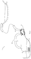
- is a schematic illustration of an inventive drainage pump assembly located in a mine,
- Fig. 2
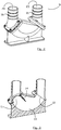
- is a schematic perspective view from above of a sedimentation trap according to a first embodiment,
- Fig. 3
- is a schematic perspective cross sectional view of the sedimentation trap according to
figure 2 , - Fig. 4
- is a schematic perspective view of a non-return valve used in the sedimentation trap according to
figure 2 , - Fig. 5
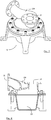
- is a schematic perspective view from above of a sedimentation trap according to a second embodiment,
- Fig. 6
- is a schematic cross sectional view of the sedimentation trap according to
figure 5 , - Fig. 7
- is a schematic perspective view from above of a sedimentation trap according to a third embodiment, and
- Fig. 8
- is a schematic perspective cross sectional view of the sedimentation trap according to
figure 7 . - The present invention relates specifically to the field of drainage pump assemblies especially configured for pumping liquid comprising solid matter, such as sand and stone material.
- Reference is initially made to
figure 1 , disclosing a preferred embodiment of a drainage pump assembly, generally designated 1. Thedrainage pump assembly 1 comprises a drainage pump 2 and an outlet conduit, generally designated 3. - The disclosed drainage pump 2 comprises an
inlet 4, apump housing 5 and apump outlet 6. Thereto, the drainage pump 2 comprises in a conventional way a hydraulic unit having a pump chamber (not disclosed), and comprises a drive unit (not disclosed). The drive unit and the pump chamber are arranged in thepump housing 5. The drive unit comprises an electrical motor arranged in the liquidtight pump housing 5, and a drive shaft extending from the electrical motor. An impeller (not disclosed) is arranged in the pump chamber and is driven in rotation by the drive shaft during operation of the drainage pump 2, wherein liquid is sucked into saidinlet 4 and pumped out of saidoutlet 6 when the drainage pump 2 is active. The pump housing 5 and the impeller, and other essential components, are preferably made of metal. The electrical motor is powered via an electrical cable extending from a power supply, and the drainage pump 2 comprises a liquid tight lead-through receiving the electrical cable. According to an alternative embodiment, the drive unit comprises an internal combustion engine and a suitable gear box arrangement, wherein the drive shaft is driven in rotation by the internal combustion engine via said gear box arrangement. Drainage pump arrangements comprising internal combustion engines are conventionally used in dry installations, i.e. the entire pump is then located above the liquid surface and an inlet pipe extend from the pump inlet into the liquid. - The drainage pump 2 may also comprise a control unit, such as an Intelligent Drive or Variable Frequency Drive (VFD), located inside the liquid
tight pump housing 4. The control unit is configured to control the operational speed of the drainage pump 2. The components of the drainage pump 2 are usually cold down by means of the liquid surrounding the drainage pump 2. The drainage pump 2 is designed and configured to be able to operate in a submerged configuration/position, i.e. during operation be located entirely under the liquid surface. However, it shall be realized that the submersible drainage pump 2 during operation must not be entirely located under the liquid surface but may continuously or occasionally be partly located above the liquid surface. - The drainage pump 2 is in the disclosed application located in a first/lower basin 7 and is intended to transport/pump liquid comprising solid matter from said first/lower basin 7 to a second/higher basin 8. Thereto, it shall be realized that it is conceivable that another drainage pump is located in the second basin 8 and intended to transport the liquid from the second basin 8 to a third basin, etc. The basins may be natural recesses/cavities/pits or prepared recesses/cavities/pits.
- Reference is now also made to
figures 2-4 in order to disclose the essential features of the invention, whereinfigures 2-4 disclose a first embodiment of a sedimentation trap. The outlet conduit 3 comprises a sedimentation trap, generally designated 9, and afirst conduit 10. Thesedimentation trap 9 has aninlet opening 11, anoutlet opening 12 and abelly 13 located between saidinlet opening 11 and saidoutlet opening 12. Thefirst conduit 10 extends between the pump chamber of the drainage pump 2 and thebelly 13 of thesedimentation trap 9. Thereto, saidfirst conduit 10 comprises a non-return valve, generally designated 14. - The
belly 13 is a structural formation arranged in such a way that liquid will become stagnant in thebelly 13 and solid matter will settle in thebelly 13 when the drainage pump 2 is not pumping liquid and thenon-return valve 14 is closed. Thus, thebelly 13 bulges in relation to theinlet opening 11 and theoutlet opening 12. Thebelly 13 may also be denominated a sump, an interior cavity, a sink, a reservoir, i.e. a structural formation that is used to temporarily store/accumulate solid matter. Theoutlet opening 12 of thesedimentation trap 9 is configured to be connected to asecond conduit 15, wherein thesecond conduit 15 is configured to transport the pumped liquid to said second basin 8. Thenon-return valve 14 is preferably arranged at the inlet opening 11 of thesedimentation trap 9. Another feasible location of the non-return valve is at theoutlet opening 6 of the drainage pump 2. - In the disclosed embodiment, the
non-return valve 14 is constituted by a flap valve and is connected to the inlet opening 11 of thesedimentation trap 9, wherein avalve disc 16 of the flap valve is located in or facing thebelly 13 and avalve seat 17 of the flap valve is facing thebelly 13. Thevalve seat 17 comprises a rim 17' arranged to engage thevalve disc 16 when the non-return valve is closed. Thevalve disc 16 and thevalve seat 17 are preferably made of metal. Thevalve disc 16 is connected to thevalve seat 17 via ahinge member 18. Thehinge member 18 is preferably made of rubber, preferably vulcanized to thevalve disc 16 andvalve seat 17, respectively. It is also feasible to use an adhesive to attach thehinge member 18 to thevalve disc 16 andvalve seat 17, respectively. The valve disc 16 (or valve member) is preferably biased towards an open position. When the pump is deactivated the liquid in the outlet conduit will force thenon-return valve 14 to close. - Preferably a centre axis of the inlet opening 11 of the
sedimentation trap 9 has a negative slope. Said centre axis extends perpendicular to the cross section area of theinlet opening 11. The term negative slope is defined in view of the flow direction of the pumped liquid when the drainage pump2 is active. Preferably a centre axis of the outlet opening 12 of thesedimentation trap 9 has a positive slope. Said centre axis extends perpendicular to the cross section area of theoutlet opening 12. The term positive slope is defined in view of the flow direction of the pumped liquid when the drainage pump2 is active. The diameter of the cross section area of theoutlet opening 12 is preferably in the range 75-125 millimeters, however both smaller and larger diameters are conceivable. - According to the disclosed embodiment, an inlet pipe fitting 19 is connected to the inlet opening 11 of the
sedimentation trap 9. The inlet pipe fitting 19 comprises aninlet opening 20, wherein a centre axis of the inlet opening 20 of the inlet pipe fitting 19 preferably extends in the vertical direction. Thereto, an outlet pipe fitting 21 is connected to the outlet opening 12 of thesedimentation trap 9. The outlet pipe fitting 21comprises anoutlet opening 22, wherein a centre axis of the outlet opening 22 of the outlet pipe fitting 21 extends in the vertical direction. The term vertical is defined having thesedimentation trap 9 standing in an operational position on a horizontal surface. According to an alternative embodiment, the centre axis of the inlet opening 20 of the inlet pipe fitting 19 is essentially parallel to the centre axis of the inlet opening 11 of thesedimentation trap 9. According to an alternative embodiment, the centre axis of the outlet opening 22 of the outlet pipe fitting 21 is essentially parallel to the centre axis of the outlet opening 12 of thesedimentation trap 9. Thus, thesedimentation trap 9 according to the first embodiment is generally U-shaped. - The
belly 13 of thesedimentation trap 9 has a belly volume V [decimeter3] that is equal to a factor X [decimeter] times the cross sectional area A [decimeter2] of the outlet opening 12 of thesedimentation trap 9, wherein the factor X is equal to or greater than 2, and wherein the factor X is equal to or less than 12. Preferably, the factor X is equal to or greater than 5, and equal to or less than 9. The belly volume V has to be large enough to be able to receive the solid matter sliding backwards into thesedimentation trap 9 when thenon-return valve 14 is closed and small enough not to generate a huge pressure drop of the pumped liquid when the drainage pump 2 is active and the pumped liquid enters thesedimentation trap 9. The belly volume V is equal to a maximum liquid volume that thesedimentation trap 9 is configured to hold/keep when adetached sedimentation trap 9 is standing in an operational position on a horizontal surface. - During operation of the drainage pump 2, i.e. when the drainage pump 2 is active and transport liquid, the
sedimentation trap 9 is configured in such a way that the pumped liquid shall fluidize the solid matter that has settled in the belly during the drainage pump 2 deactivation time or the time thenon-return valve 14 as been closed. Thus, the pumped liquid flow shall be directed towards the location of the belly where the solid matter is intended to settle. - It shall be pointed out that the drainage pump 2 must not be completely deactivated for the
non-return valve 14 to close the outlet conduit 3. The drainage pump 2 can be operated by means of a of the control unit. The control unit may be built-in into the drainage pump 2, i.e. preferably located into the pump top, or the drainage pump 2 may be operatively connected to an external control unit. In an operational mode wherein the operational speed of the drainage pump 2 is below the operational speed required to transport liquid through the outlet conduit 3, the non-return valve 3 will close due to the flow resistance from the liquid that is present in the outlet conduit 3. - Reference is now made to
figures 5 and 6 , disclosing a second embodiment of thesedimentation trap 9, and only differences in view of the first embodiment will be discussed. The corresponding elements/components have been given the same reference number throughout the specification. - In the second embodiment of the
sedimentation trap 9, thesedimentation trap 9 is arranged/designed as a maze. In the disclosed embodiment, a centre axis of theinlet opening 11 and a centre axis of theoutlet opening 12 are essentially parallel and preferably aligned with each other. Thesedimentation trap 9 comprises at least two lobes/windings 23 providing a generally helical shaped flow path from the inlet opening 11 to theoutlet opening 12, wherein the helical shaped flow path comprises at least one full turn. In the disclosed embodiment thesedimentation trap 9 comprises threelobes 23. The advantage of having a helical shaped flow path is that the orientation of thesedimentation trap 9 does not have negative effect on the function of thesedimentation trap 9. Thebelly 13 will be arranged in at least one of thelobes 23. - Reference is now made to
figures 7 and 8 , disclosing a third embodiment of thesedimentation trap 9, and only differences in view of the first embodiment will be discussed. The corresponding elements/components have been given the same reference number throughout the specification. - In the third embodiment of the
sedimentation trap 9, thesedimentation trap 9 is arranged/designed as a cyclone. In the disclosed embodiment thesedimentation trap 9 comprises aninlet pipe 24 extending from the inlet opening 11 to thebelly 13. Theinlet pipe 24 is arranged above thebelly 13, and theinlet pipe 24 is configured to create a swirling liquid flow in thebelly 13. Thereto, a centre axis of theoutlet opening 12 is arranged essentially vertical, and theoutlet opening 12 is arranged at the top of thesedimentation trap 9. Thus, the disclosed embodiment provides a generally cyclone shaped liquid flow, entering thebelly 13 in a tangential direction and leaving thebelly 13 in an axial direction at the top of thesedimentation trap 9. - The invention is not limited only to the embodiments described above and shown in the drawings, which primarily have an illustrative and exemplifying purpose. This patent application is intended to cover all adjustments and variants of the preferred embodiments described herein, thus the present invention is defined by the wording of the appended claims and thus, the equipment may be modified in all kinds of ways within the scope of the appended claims.
- It shall also be pointed out that all information about/concerning terms such as above, under, upper, lower, etc., shall be interpreted/read having the equipment oriented according to the figures, having the drawings oriented such that the references can be properly read. Thus, such terms only indicates mutual relations in the shown embodiments, which relations may be changed if the inventive equipment is provided with another structure/design.
- It shall also be pointed out that even thus it is not explicitly stated that features from a specific embodiment may be combined with features from another embodiment, the combination shall be considered obvious, if the combination is possible.
- Throughout this specification and the claims which follows, unless the context requires otherwise, the word "comprise", and variations such as "comprises" or "comprising", will be understood to imply the inclusion of a stated integer or steps or group of integers or steps but not the exclusion of any other integer or step or group of integers or steps.
Claims (14)
- A drainage pump assembly comprising a drainage pump (2) and an outlet conduit (3) connected to said drainage pump (2), the drainage pump (2) comprising a pump chamber and being configured to pump liquid comprising solid matter, characterized in that the outlet conduit (3) comprises:- a sedimentation trap (9) having an inlet opening (11), an outlet opening (12) and a belly (13) located between said inlet opening (11) and said outlet opening (12), and- a first conduit (10) extending between the pump chamber of the drainage pump (2) and the belly (13) of the sedimentation trap (9),wherein said first conduit (10) comprises a non-return valve (14), and wherein the outlet opening (12) of the sedimentation trap (9) is configured to be connected to a second conduit (15).
- The drainage pump assembly according to claim 1, wherein the outlet conduit (3) comprises a second conduit (15) connected to the outlet opening (12) of the sedimentation trap (9).
- The drainage pump assembly according to claim 1 or 2, wherein the belly (13) of the sedimentation trap (9) has a belly volume V [dm3] that is equal to a factor X [dm] times the cross sectional area A [dm2] of the outlet opening (12) of the sedimentation trap (9), wherein the factor X is equal to or greater than 2.
- The drainage pump assembly according to any of claims 1-3, wherein the belly (13) of the sedimentation trap (9) has a belly volume V [dm3] that is equal to a factor X [dm] times the cross sectional area A [dm2] of the outlet opening (12) of the sedimentation trap (9), wherein the factor X is equal to or less than 12.
- The drainage pump assembly according to claim 3 or 4, wherein the belly volume V is equal to a maximum liquid volume that the sedimentation trap (9) is configured to hold when the sedimentation trap (9) is standing in an operational position on a horizontal surface.
- The drainage pump assembly according to any preceding claim, wherein a centre axis of the inlet opening (11) of the sedimentation trap (9) has a negative slope.
- The drainage pump assembly according to any preceding claim, wherein a centre axis of the outlet opening (12) of the sedimentation trap (9) has a positive slope.
- The drainage pump assembly according to any preceding claim, wherein an inlet pipe fitting (19) is connected to the inlet opening (11) of the sedimentation trap (9).
- The drainage pump assembly according to claim 8, wherein the inlet pipe fitting (19) comprises an inlet opening (20), wherein a centre axis of the inlet opening (20) of the inlet pipe fitting (19) extends in the vertical direction.
- The drainage pump assembly according to any preceding claim, wherein an outlet pipe fitting (21) is connected to the outlet opening (12) of the sedimentation trap (9).
- The drainage pump assembly according to claim 10, wherein the outlet pipe fitting (21) comprises an outlet opening (22), wherein a centre axis of the outlet opening (22) of the outlet pipe fitting (21) extends in the vertical direction.
- The drainage pump assembly according to any preceding claim, wherein the non-return valve (14) is connected to the inlet opening (11) of the sedimentation trap (9).
- The drainage pump assembly according to claim 12, wherein the non-return valve (14) is constituted by a flap valve.
- The drainage pump assembly according to claim 12 or 13, wherein a valve member (16) of the non-return valve (14) is biased towards an open position.
Priority Applications (13)
| Application Number | Priority Date | Filing Date | Title |
|---|---|---|---|
| PL17156823T PL3364027T3 (en) | 2017-02-20 | 2017-02-20 | Drainage pump assembly |
| PT171568231T PT3364027T (en) | 2017-02-20 | 2017-02-20 | Drainage pump assembly |
| ES17156823T ES2774523T3 (en) | 2017-02-20 | 2017-02-20 | Drain pump assembly |
| EP17156823.1A EP3364027B1 (en) | 2017-02-20 | 2017-02-20 | Drainage pump assembly |
| MX2019008892A MX2019008892A (en) | 2017-02-20 | 2018-02-19 | Drainage pump assembly. |
| CN201880012734.8A CN110325735B (en) | 2017-02-20 | 2018-02-19 | Drain pump assembly |
| US16/486,550 US20210131408A1 (en) | 2017-02-20 | 2018-02-19 | Drainage pump assembly |
| PE2019001699A PE20191314A1 (en) | 2017-02-20 | 2018-02-19 | DRAIN PUMP ASSEMBLY |
| PCT/EP2018/053983 WO2018150014A1 (en) | 2017-02-20 | 2018-02-19 | Drainage pump assembly |
| AU2018222780A AU2018222780A1 (en) | 2017-02-20 | 2018-02-19 | Drainage pump assembly |
| BR112019017089A BR112019017089A2 (en) | 2017-02-20 | 2018-02-19 | drain pump assembly |
| CL2019002330A CL2019002330A1 (en) | 2017-02-20 | 2019-08-16 | Drain pump assembly. |
| ZA2019/06207A ZA201906207B (en) | 2017-02-20 | 2019-09-19 | Drainage pump assembly |
Applications Claiming Priority (1)
| Application Number | Priority Date | Filing Date | Title |
|---|---|---|---|
| EP17156823.1A EP3364027B1 (en) | 2017-02-20 | 2017-02-20 | Drainage pump assembly |
Publications (2)
| Publication Number | Publication Date |
|---|---|
| EP3364027A1 true EP3364027A1 (en) | 2018-08-22 |
| EP3364027B1 EP3364027B1 (en) | 2019-11-27 |
Family
ID=58192093
Family Applications (1)
| Application Number | Title | Priority Date | Filing Date |
|---|---|---|---|
| EP17156823.1A Active EP3364027B1 (en) | 2017-02-20 | 2017-02-20 | Drainage pump assembly |
Country Status (13)
| Country | Link |
|---|---|
| US (1) | US20210131408A1 (en) |
| EP (1) | EP3364027B1 (en) |
| CN (1) | CN110325735B (en) |
| AU (1) | AU2018222780A1 (en) |
| BR (1) | BR112019017089A2 (en) |
| CL (1) | CL2019002330A1 (en) |
| ES (1) | ES2774523T3 (en) |
| MX (1) | MX2019008892A (en) |
| PE (1) | PE20191314A1 (en) |
| PL (1) | PL3364027T3 (en) |
| PT (1) | PT3364027T (en) |
| WO (1) | WO2018150014A1 (en) |
| ZA (1) | ZA201906207B (en) |
Families Citing this family (1)
| Publication number | Priority date | Publication date | Assignee | Title |
|---|---|---|---|---|
| USD949924S1 (en) * | 2019-04-17 | 2022-04-26 | Xylem Europe Gmbh | Pump |
Citations (3)
| Publication number | Priority date | Publication date | Assignee | Title |
|---|---|---|---|---|
| US3963073A (en) * | 1973-09-12 | 1976-06-15 | Laval Claude C | Purging apparatus |
| WO2009118618A2 (en) * | 2008-03-26 | 2009-10-01 | Idei Critica, Lda | Multi-functional collector for grey water |
| US20160288021A1 (en) * | 2015-03-31 | 2016-10-06 | ClearCove Systems, Inc. | System for processing food process waste water including purification and optional recycling of purified waste water |
-
2017
- 2017-02-20 PL PL17156823T patent/PL3364027T3/en unknown
- 2017-02-20 ES ES17156823T patent/ES2774523T3/en active Active
- 2017-02-20 EP EP17156823.1A patent/EP3364027B1/en active Active
- 2017-02-20 PT PT171568231T patent/PT3364027T/en unknown
-
2018
- 2018-02-19 CN CN201880012734.8A patent/CN110325735B/en not_active Expired - Fee Related
- 2018-02-19 PE PE2019001699A patent/PE20191314A1/en unknown
- 2018-02-19 WO PCT/EP2018/053983 patent/WO2018150014A1/en not_active Ceased
- 2018-02-19 AU AU2018222780A patent/AU2018222780A1/en not_active Abandoned
- 2018-02-19 US US16/486,550 patent/US20210131408A1/en not_active Abandoned
- 2018-02-19 BR BR112019017089A patent/BR112019017089A2/en not_active Application Discontinuation
- 2018-02-19 MX MX2019008892A patent/MX2019008892A/en unknown
-
2019
- 2019-08-16 CL CL2019002330A patent/CL2019002330A1/en unknown
- 2019-09-19 ZA ZA2019/06207A patent/ZA201906207B/en unknown
Patent Citations (3)
| Publication number | Priority date | Publication date | Assignee | Title |
|---|---|---|---|---|
| US3963073A (en) * | 1973-09-12 | 1976-06-15 | Laval Claude C | Purging apparatus |
| WO2009118618A2 (en) * | 2008-03-26 | 2009-10-01 | Idei Critica, Lda | Multi-functional collector for grey water |
| US20160288021A1 (en) * | 2015-03-31 | 2016-10-06 | ClearCove Systems, Inc. | System for processing food process waste water including purification and optional recycling of purified waste water |
Also Published As
| Publication number | Publication date |
|---|---|
| CL2019002330A1 (en) | 2019-11-29 |
| PE20191314A1 (en) | 2019-09-23 |
| CN110325735A (en) | 2019-10-11 |
| MX2019008892A (en) | 2020-01-30 |
| ZA201906207B (en) | 2021-02-24 |
| PT3364027T (en) | 2020-02-19 |
| AU2018222780A1 (en) | 2019-10-10 |
| BR112019017089A2 (en) | 2020-04-07 |
| PL3364027T3 (en) | 2020-06-15 |
| WO2018150014A1 (en) | 2018-08-23 |
| CN110325735B (en) | 2021-09-07 |
| US20210131408A1 (en) | 2021-05-06 |
| EP3364027B1 (en) | 2019-11-27 |
| ES2774523T3 (en) | 2020-07-21 |
Similar Documents
| Publication | Publication Date | Title |
|---|---|---|
| US9835168B2 (en) | Casing liner for sewage pump and sewage pump with the same | |
| WO2005040616A1 (en) | Water-lifting pump device and operation control method for the same | |
| US12031554B2 (en) | Open impeller for submergible pump configured for pumping liquid comprising abrasive matter | |
| KR101109518B1 (en) | Submersible Pump for Drainage | |
| EP3364027B1 (en) | Drainage pump assembly | |
| US10330110B2 (en) | Pump impeller | |
| CN106194776B (en) | A kind of deep well pump of band from sand discharge structure | |
| CN107035404A (en) | A kind of efficient mining centrifugal multistage pump station of the full malleation of chopped-off head subduction | |
| CN201129309Y (en) | Large-sized flush type mining water discharge pump | |
| CN105822522A (en) | Oil well pump for oil exploitation | |
| CN208546323U (en) | A kind of sand-proof type injection immersible pump | |
| EP3647501A1 (en) | Portable pump station arrangement | |
| AU2012101036A4 (en) | Windows Pump | |
| CN219119468U (en) | Horizontal type installed deep well pump | |
| CN210799502U (en) | Drainage pump for digging pile | |
| EP3839205A1 (en) | Portable pump station arrangement | |
| CN210290160U (en) | Portable cutting submersible sewage pump with water entering from bottom | |
| CN206329508U (en) | A kind of immersible pump | |
| CN204003593U (en) | A kind of impeller and water pump thereof | |
| CN106438393B (en) | A kind of antiwear prefabricated pumping plant | |
| CN219549208U (en) | Waterlogging drainage pump | |
| CN210397128U (en) | Portable cutting submersible sewage pump with water entering from middle | |
| CN204041453U (en) | A kind of screw submersible pump | |
| CN201318307Y (en) | Gas exhaust type rapid water-feeding device free of water injection for centrifugal water pump in deep well | |
| CN201554659U (en) | Multi-level immersible pump |
Legal Events
| Date | Code | Title | Description |
|---|---|---|---|
| PUAI | Public reference made under article 153(3) epc to a published international application that has entered the european phase |
Free format text: ORIGINAL CODE: 0009012 |
|
| STAA | Information on the status of an ep patent application or granted ep patent |
Free format text: STATUS: THE APPLICATION HAS BEEN PUBLISHED |
|
| AK | Designated contracting states |
Kind code of ref document: A1 Designated state(s): AL AT BE BG CH CY CZ DE DK EE ES FI FR GB GR HR HU IE IS IT LI LT LU LV MC MK MT NL NO PL PT RO RS SE SI SK SM TR |
|
| AX | Request for extension of the european patent |
Extension state: BA ME |
|
| STAA | Information on the status of an ep patent application or granted ep patent |
Free format text: STATUS: REQUEST FOR EXAMINATION WAS MADE |
|
| 17P | Request for examination filed |
Effective date: 20190130 |
|
| RBV | Designated contracting states (corrected) |
Designated state(s): AL AT BE BG CH CY CZ DE DK EE ES FI FR GB GR HR HU IE IS IT LI LT LU LV MC MK MT NL NO PL PT RO RS SE SI SK SM TR |
|
| RIC1 | Information provided on ipc code assigned before grant |
Ipc: F04B 15/02 20060101AFI20190520BHEP Ipc: F04B 53/20 20060101ALI20190520BHEP Ipc: F04B 47/00 20060101ALI20190520BHEP |
|
| GRAP | Despatch of communication of intention to grant a patent |
Free format text: ORIGINAL CODE: EPIDOSNIGR1 |
|
| STAA | Information on the status of an ep patent application or granted ep patent |
Free format text: STATUS: GRANT OF PATENT IS INTENDED |
|
| INTG | Intention to grant announced |
Effective date: 20190719 |
|
| RAP1 | Party data changed (applicant data changed or rights of an application transferred) |
Owner name: XYLEM EUROPE GMBH |
|
| GRAS | Grant fee paid |
Free format text: ORIGINAL CODE: EPIDOSNIGR3 |
|
| GRAA | (expected) grant |
Free format text: ORIGINAL CODE: 0009210 |
|
| STAA | Information on the status of an ep patent application or granted ep patent |
Free format text: STATUS: THE PATENT HAS BEEN GRANTED |
|
| AK | Designated contracting states |
Kind code of ref document: B1 Designated state(s): AL AT BE BG CH CY CZ DE DK EE ES FI FR GB GR HR HU IE IS IT LI LT LU LV MC MK MT NL NO PL PT RO RS SE SI SK SM TR |
|
| REG | Reference to a national code |
Ref country code: GB Ref legal event code: FG4D |
|
| REG | Reference to a national code |
Ref country code: CH Ref legal event code: EP |
|
| REG | Reference to a national code |
Ref country code: AT Ref legal event code: REF Ref document number: 1206946 Country of ref document: AT Kind code of ref document: T Effective date: 20191215 |
|
| REG | Reference to a national code |
Ref country code: DE Ref legal event code: R096 Ref document number: 602017008990 Country of ref document: DE |
|
| REG | Reference to a national code |
Ref country code: IE Ref legal event code: FG4D |
|
| REG | Reference to a national code |
Ref country code: SE Ref legal event code: TRGR |
|
| REG | Reference to a national code |
Ref country code: PT Ref legal event code: SC4A Ref document number: 3364027 Country of ref document: PT Date of ref document: 20200219 Kind code of ref document: T Free format text: AVAILABILITY OF NATIONAL TRANSLATION Effective date: 20200206 |
|
| REG | Reference to a national code |
Ref country code: NL Ref legal event code: MP Effective date: 20191127 |
|
| REG | Reference to a national code |
Ref country code: LT Ref legal event code: MG4D |
|
| PG25 | Lapsed in a contracting state [announced via postgrant information from national office to epo] |
Ref country code: LV Free format text: LAPSE BECAUSE OF FAILURE TO SUBMIT A TRANSLATION OF THE DESCRIPTION OR TO PAY THE FEE WITHIN THE PRESCRIBED TIME-LIMIT Effective date: 20191127 Ref country code: NL Free format text: LAPSE BECAUSE OF FAILURE TO SUBMIT A TRANSLATION OF THE DESCRIPTION OR TO PAY THE FEE WITHIN THE PRESCRIBED TIME-LIMIT Effective date: 20191127 Ref country code: GR Free format text: LAPSE BECAUSE OF FAILURE TO SUBMIT A TRANSLATION OF THE DESCRIPTION OR TO PAY THE FEE WITHIN THE PRESCRIBED TIME-LIMIT Effective date: 20200228 Ref country code: BG Free format text: LAPSE BECAUSE OF FAILURE TO SUBMIT A TRANSLATION OF THE DESCRIPTION OR TO PAY THE FEE WITHIN THE PRESCRIBED TIME-LIMIT Effective date: 20200227 Ref country code: NO Free format text: LAPSE BECAUSE OF FAILURE TO SUBMIT A TRANSLATION OF THE DESCRIPTION OR TO PAY THE FEE WITHIN THE PRESCRIBED TIME-LIMIT Effective date: 20200227 Ref country code: FI Free format text: LAPSE BECAUSE OF FAILURE TO SUBMIT A TRANSLATION OF THE DESCRIPTION OR TO PAY THE FEE WITHIN THE PRESCRIBED TIME-LIMIT Effective date: 20191127 Ref country code: LT Free format text: LAPSE BECAUSE OF FAILURE TO SUBMIT A TRANSLATION OF THE DESCRIPTION OR TO PAY THE FEE WITHIN THE PRESCRIBED TIME-LIMIT Effective date: 20191127 |
|
| PG25 | Lapsed in a contracting state [announced via postgrant information from national office to epo] |
Ref country code: RS Free format text: LAPSE BECAUSE OF FAILURE TO SUBMIT A TRANSLATION OF THE DESCRIPTION OR TO PAY THE FEE WITHIN THE PRESCRIBED TIME-LIMIT Effective date: 20191127 Ref country code: IS Free format text: LAPSE BECAUSE OF FAILURE TO SUBMIT A TRANSLATION OF THE DESCRIPTION OR TO PAY THE FEE WITHIN THE PRESCRIBED TIME-LIMIT Effective date: 20200327 Ref country code: HR Free format text: LAPSE BECAUSE OF FAILURE TO SUBMIT A TRANSLATION OF THE DESCRIPTION OR TO PAY THE FEE WITHIN THE PRESCRIBED TIME-LIMIT Effective date: 20191127 |
|
| PG25 | Lapsed in a contracting state [announced via postgrant information from national office to epo] |
Ref country code: AL Free format text: LAPSE BECAUSE OF FAILURE TO SUBMIT A TRANSLATION OF THE DESCRIPTION OR TO PAY THE FEE WITHIN THE PRESCRIBED TIME-LIMIT Effective date: 20191127 |
|
| REG | Reference to a national code |
Ref country code: ES Ref legal event code: FG2A Ref document number: 2774523 Country of ref document: ES Kind code of ref document: T3 Effective date: 20200721 |
|
| PG25 | Lapsed in a contracting state [announced via postgrant information from national office to epo] |
Ref country code: RO Free format text: LAPSE BECAUSE OF FAILURE TO SUBMIT A TRANSLATION OF THE DESCRIPTION OR TO PAY THE FEE WITHIN THE PRESCRIBED TIME-LIMIT Effective date: 20191127 Ref country code: EE Free format text: LAPSE BECAUSE OF FAILURE TO SUBMIT A TRANSLATION OF THE DESCRIPTION OR TO PAY THE FEE WITHIN THE PRESCRIBED TIME-LIMIT Effective date: 20191127 Ref country code: DK Free format text: LAPSE BECAUSE OF FAILURE TO SUBMIT A TRANSLATION OF THE DESCRIPTION OR TO PAY THE FEE WITHIN THE PRESCRIBED TIME-LIMIT Effective date: 20191127 Ref country code: CZ Free format text: LAPSE BECAUSE OF FAILURE TO SUBMIT A TRANSLATION OF THE DESCRIPTION OR TO PAY THE FEE WITHIN THE PRESCRIBED TIME-LIMIT Effective date: 20191127 |
|
| REG | Reference to a national code |
Ref country code: DE Ref legal event code: R097 Ref document number: 602017008990 Country of ref document: DE |
|
| PG25 | Lapsed in a contracting state [announced via postgrant information from national office to epo] |
Ref country code: SM Free format text: LAPSE BECAUSE OF FAILURE TO SUBMIT A TRANSLATION OF THE DESCRIPTION OR TO PAY THE FEE WITHIN THE PRESCRIBED TIME-LIMIT Effective date: 20191127 Ref country code: SK Free format text: LAPSE BECAUSE OF FAILURE TO SUBMIT A TRANSLATION OF THE DESCRIPTION OR TO PAY THE FEE WITHIN THE PRESCRIBED TIME-LIMIT Effective date: 20191127 |
|
| REG | Reference to a national code |
Ref country code: AT Ref legal event code: MK05 Ref document number: 1206946 Country of ref document: AT Kind code of ref document: T Effective date: 20191127 |
|
| REG | Reference to a national code |
Ref country code: CH Ref legal event code: PL |
|
| PLBE | No opposition filed within time limit |
Free format text: ORIGINAL CODE: 0009261 |
|
| STAA | Information on the status of an ep patent application or granted ep patent |
Free format text: STATUS: NO OPPOSITION FILED WITHIN TIME LIMIT |
|
| REG | Reference to a national code |
Ref country code: BE Ref legal event code: MM Effective date: 20200229 |
|
| PG25 | Lapsed in a contracting state [announced via postgrant information from national office to epo] |
Ref country code: MC Free format text: LAPSE BECAUSE OF FAILURE TO SUBMIT A TRANSLATION OF THE DESCRIPTION OR TO PAY THE FEE WITHIN THE PRESCRIBED TIME-LIMIT Effective date: 20191127 Ref country code: LU Free format text: LAPSE BECAUSE OF NON-PAYMENT OF DUE FEES Effective date: 20200220 |
|
| 26N | No opposition filed |
Effective date: 20200828 |
|
| PG25 | Lapsed in a contracting state [announced via postgrant information from national office to epo] |
Ref country code: LI Free format text: LAPSE BECAUSE OF NON-PAYMENT OF DUE FEES Effective date: 20200229 Ref country code: SI Free format text: LAPSE BECAUSE OF FAILURE TO SUBMIT A TRANSLATION OF THE DESCRIPTION OR TO PAY THE FEE WITHIN THE PRESCRIBED TIME-LIMIT Effective date: 20191127 Ref country code: CH Free format text: LAPSE BECAUSE OF NON-PAYMENT OF DUE FEES Effective date: 20200229 Ref country code: AT Free format text: LAPSE BECAUSE OF FAILURE TO SUBMIT A TRANSLATION OF THE DESCRIPTION OR TO PAY THE FEE WITHIN THE PRESCRIBED TIME-LIMIT Effective date: 20191127 |
|
| PG25 | Lapsed in a contracting state [announced via postgrant information from national office to epo] |
Ref country code: IE Free format text: LAPSE BECAUSE OF NON-PAYMENT OF DUE FEES Effective date: 20200220 Ref country code: FR Free format text: LAPSE BECAUSE OF NON-PAYMENT OF DUE FEES Effective date: 20200229 Ref country code: IT Free format text: LAPSE BECAUSE OF FAILURE TO SUBMIT A TRANSLATION OF THE DESCRIPTION OR TO PAY THE FEE WITHIN THE PRESCRIBED TIME-LIMIT Effective date: 20191127 |
|
| PG25 | Lapsed in a contracting state [announced via postgrant information from national office to epo] |
Ref country code: BE Free format text: LAPSE BECAUSE OF NON-PAYMENT OF DUE FEES Effective date: 20200229 |
|
| PGFP | Annual fee paid to national office [announced via postgrant information from national office to epo] |
Ref country code: PT Payment date: 20210204 Year of fee payment: 5 |
|
| PGFP | Annual fee paid to national office [announced via postgrant information from national office to epo] |
Ref country code: DE Payment date: 20210225 Year of fee payment: 5 Ref country code: ES Payment date: 20210301 Year of fee payment: 5 Ref country code: PL Payment date: 20210203 Year of fee payment: 5 |
|
| GBPC | Gb: european patent ceased through non-payment of renewal fee |
Effective date: 20210220 |
|
| PG25 | Lapsed in a contracting state [announced via postgrant information from national office to epo] |
Ref country code: GB Free format text: LAPSE BECAUSE OF NON-PAYMENT OF DUE FEES Effective date: 20210220 |
|
| PG25 | Lapsed in a contracting state [announced via postgrant information from national office to epo] |
Ref country code: TR Free format text: LAPSE BECAUSE OF FAILURE TO SUBMIT A TRANSLATION OF THE DESCRIPTION OR TO PAY THE FEE WITHIN THE PRESCRIBED TIME-LIMIT Effective date: 20191127 Ref country code: MT Free format text: LAPSE BECAUSE OF FAILURE TO SUBMIT A TRANSLATION OF THE DESCRIPTION OR TO PAY THE FEE WITHIN THE PRESCRIBED TIME-LIMIT Effective date: 20191127 Ref country code: CY Free format text: LAPSE BECAUSE OF FAILURE TO SUBMIT A TRANSLATION OF THE DESCRIPTION OR TO PAY THE FEE WITHIN THE PRESCRIBED TIME-LIMIT Effective date: 20191127 |
|
| PG25 | Lapsed in a contracting state [announced via postgrant information from national office to epo] |
Ref country code: MK Free format text: LAPSE BECAUSE OF FAILURE TO SUBMIT A TRANSLATION OF THE DESCRIPTION OR TO PAY THE FEE WITHIN THE PRESCRIBED TIME-LIMIT Effective date: 20191127 |
|
| REG | Reference to a national code |
Ref country code: DE Ref legal event code: R119 Ref document number: 602017008990 Country of ref document: DE |
|
| PG25 | Lapsed in a contracting state [announced via postgrant information from national office to epo] |
Ref country code: PT Free format text: LAPSE BECAUSE OF NON-PAYMENT OF DUE FEES Effective date: 20220822 |
|
| PG25 | Lapsed in a contracting state [announced via postgrant information from national office to epo] |
Ref country code: DE Free format text: LAPSE BECAUSE OF NON-PAYMENT OF DUE FEES Effective date: 20220901 |
|
| REG | Reference to a national code |
Ref country code: ES Ref legal event code: FD2A Effective date: 20230330 |
|
| PG25 | Lapsed in a contracting state [announced via postgrant information from national office to epo] |
Ref country code: ES Free format text: LAPSE BECAUSE OF NON-PAYMENT OF DUE FEES Effective date: 20220221 |
|
| PG25 | Lapsed in a contracting state [announced via postgrant information from national office to epo] |
Ref country code: PL Free format text: LAPSE BECAUSE OF NON-PAYMENT OF DUE FEES Effective date: 20220220 |
|
| PGFP | Annual fee paid to national office [announced via postgrant information from national office to epo] |
Ref country code: SE Payment date: 20240307 Year of fee payment: 8 |
|
| REG | Reference to a national code |
Ref country code: SE Ref legal event code: EUG |