EP3364024A1 - Multi-platform wind turbine tower - Google Patents
Multi-platform wind turbine tower Download PDFInfo
- Publication number
- EP3364024A1 EP3364024A1 EP16856979.6A EP16856979A EP3364024A1 EP 3364024 A1 EP3364024 A1 EP 3364024A1 EP 16856979 A EP16856979 A EP 16856979A EP 3364024 A1 EP3364024 A1 EP 3364024A1
- Authority
- EP
- European Patent Office
- Prior art keywords
- tower
- turbine
- coronation
- profile
- turbines
- Prior art date
- Legal status (The legal status is an assumption and is not a legal conclusion. Google has not performed a legal analysis and makes no representation as to the accuracy of the status listed.)
- Granted
Links
Images


Classifications
-
- E—FIXED CONSTRUCTIONS
- E04—BUILDING
- E04H—BUILDINGS OR LIKE STRUCTURES FOR PARTICULAR PURPOSES; SWIMMING OR SPLASH BATHS OR POOLS; MASTS; FENCING; TENTS OR CANOPIES, IN GENERAL
- E04H12/00—Towers; Masts or poles; Chimney stacks; Water-towers; Methods of erecting such structures
- E04H12/02—Structures made of specified materials
- E04H12/12—Structures made of specified materials of concrete or other stone-like material, with or without internal or external reinforcements, e.g. with metal coverings, with permanent form elements
-
- E—FIXED CONSTRUCTIONS
- E04—BUILDING
- E04H—BUILDINGS OR LIKE STRUCTURES FOR PARTICULAR PURPOSES; SWIMMING OR SPLASH BATHS OR POOLS; MASTS; FENCING; TENTS OR CANOPIES, IN GENERAL
- E04H12/00—Towers; Masts or poles; Chimney stacks; Water-towers; Methods of erecting such structures
- E04H12/34—Arrangements for erecting or lowering towers, masts, poles, chimney stacks, or the like
- E04H12/342—Arrangements for stacking tower sections on top of each other
-
- F—MECHANICAL ENGINEERING; LIGHTING; HEATING; WEAPONS; BLASTING
- F03—MACHINES OR ENGINES FOR LIQUIDS; WIND, SPRING, OR WEIGHT MOTORS; PRODUCING MECHANICAL POWER OR A REACTIVE PROPULSIVE THRUST, NOT OTHERWISE PROVIDED FOR
- F03D—WIND MOTORS
- F03D13/00—Assembly, mounting or commissioning of wind motors; Arrangements specially adapted for transporting wind motor components
- F03D13/20—Arrangements for mounting or supporting wind motors; Masts or towers for wind motors
-
- F—MECHANICAL ENGINEERING; LIGHTING; HEATING; WEAPONS; BLASTING
- F05—INDEXING SCHEMES RELATING TO ENGINES OR PUMPS IN VARIOUS SUBCLASSES OF CLASSES F01-F04
- F05B—INDEXING SCHEME RELATING TO WIND, SPRING, WEIGHT, INERTIA OR LIKE MOTORS, TO MACHINES OR ENGINES FOR LIQUIDS COVERED BY SUBCLASSES F03B, F03D AND F03G
- F05B2240/00—Components
- F05B2240/20—Rotors
- F05B2240/21—Rotors for wind turbines
- F05B2240/221—Rotors for wind turbines with horizontal axis
-
- F—MECHANICAL ENGINEERING; LIGHTING; HEATING; WEAPONS; BLASTING
- F05—INDEXING SCHEMES RELATING TO ENGINES OR PUMPS IN VARIOUS SUBCLASSES OF CLASSES F01-F04
- F05B—INDEXING SCHEME RELATING TO WIND, SPRING, WEIGHT, INERTIA OR LIKE MOTORS, TO MACHINES OR ENGINES FOR LIQUIDS COVERED BY SUBCLASSES F03B, F03D AND F03G
- F05B2240/00—Components
- F05B2240/90—Mounting on supporting structures or systems
- F05B2240/91—Mounting on supporting structures or systems on a stationary structure
- F05B2240/912—Mounting on supporting structures or systems on a stationary structure on a tower
-
- Y—GENERAL TAGGING OF NEW TECHNOLOGICAL DEVELOPMENTS; GENERAL TAGGING OF CROSS-SECTIONAL TECHNOLOGIES SPANNING OVER SEVERAL SECTIONS OF THE IPC; TECHNICAL SUBJECTS COVERED BY FORMER USPC CROSS-REFERENCE ART COLLECTIONS [XRACs] AND DIGESTS
- Y02—TECHNOLOGIES OR APPLICATIONS FOR MITIGATION OR ADAPTATION AGAINST CLIMATE CHANGE
- Y02E—REDUCTION OF GREENHOUSE GAS [GHG] EMISSIONS, RELATED TO ENERGY GENERATION, TRANSMISSION OR DISTRIBUTION
- Y02E10/00—Energy generation through renewable energy sources
- Y02E10/70—Wind energy
- Y02E10/728—Onshore wind turbines
-
- Y—GENERAL TAGGING OF NEW TECHNOLOGICAL DEVELOPMENTS; GENERAL TAGGING OF CROSS-SECTIONAL TECHNOLOGIES SPANNING OVER SEVERAL SECTIONS OF THE IPC; TECHNICAL SUBJECTS COVERED BY FORMER USPC CROSS-REFERENCE ART COLLECTIONS [XRACs] AND DIGESTS
- Y02—TECHNOLOGIES OR APPLICATIONS FOR MITIGATION OR ADAPTATION AGAINST CLIMATE CHANGE
- Y02P—CLIMATE CHANGE MITIGATION TECHNOLOGIES IN THE PRODUCTION OR PROCESSING OF GOODS
- Y02P70/00—Climate change mitigation technologies in the production process for final industrial or consumer products
- Y02P70/50—Manufacturing or production processes characterised by the final manufactured product
Definitions
- the present invention relates to a wind turbine tower of those meant to support the corresponding wind turbine as a means for generating electrical energy.
- the object of the invention is to provide a multi-platform or multi-turbine tower that assists in cost savings in the manufacture of these types of structures, such that the same does not need to be designed specifically for each type of turbine present in the market but, using a single tower model, such as with a 120 meter shaft, the tower can be perfectly used for a plurality of turbines of various manufacturers, such that this polyvalent use allows obtaining greatly significant economic savings in the long run.
- invention patent P201430312 by the applicant describes a structure based on frustoconical sections of different inclinations, which allows obtaining from straight segments a broken profile as close as possible to the theoretical optimum curved profile intended for the tower, thereby reducing the cost of manufacture of these type of structures, this structure continues requiring a specific design of each tower for each turbine.
- the present invention bases its features on obtaining a tower from sections that define segments for said frustoconical configuration tower, with the special particularity that from specific features of the design of the tower it is possible for the tower to have an extremely versatile nature, which is value for supporting with full safety guarantees various types of turbines available in the market with the interposition of one or possibly two simple adaptors.
- the tower design consists in a load envelope according to the specifications of each of the manufacturers.
- the geometrical fit is based on parameters such as the maximum diameter admitted at blade tip and the frequency range to prevent the tower from entering in resonance and causing the amplification of the acting loads.
- the division into sections of the tower is defined by the transportation criteria, preferably limiting the maximum section weight to 55 tons, its maximum width to 4.5 meters, and its maximum length to 24 meters.
- the data corresponding to the various types of turbines are used to calculate upper and lower limits thereof.
- a multi-platform or multi-turbine tower is obtained that can support the loads of many different market-available turbines; as each turbine has securing bolts arranged annularly, with a diameter that is different for different turbines, it is necessary to adapt the diameter of the upper end or coronation of the tower to the diameter of the lower securing means of the turbine, for which the inclusion has been foreseen of adaptors or reels, embodied as metal bodies with a preferably frustoconical configuration, which can converge or diverge in an upward sense so that in every case a lower circular base is defined with a diameter matching that of the tower coronation, with a peripheral flange having orifices for passage of the corresponding securing bolts, while the upper diameter of the reel will be different for each turbine type, according to the specific needs of each case, and can be greater or smaller than the diameter of the tower coronation, consequently determining the inverted or non-inverted arrangement of the frustoconical configuration of the reel.
- peripheral flange will also be defined having the corresponding securing orifices for bolting the turbine.
- the generatrix of the adaptor does not have to be precisely straight to obtain the same end, such that it could be curved or broken, without this affecting the essence of the invention as this would merely correspond to design alternatives.
- This second adapter consists in a type of circular crown, with a wedge-like profile, i.e. with a varying thickness, the variation in width between the ends thereof obviously depends on the change in the inclination of the blades that must be achieved.
- a change in 1 degree of the verticality plane of the blades would increase by more than one meter the separation of the tips of said blades with respect to the tower at said tip area for blades measuring 60 meters.
- this wedge-like element is placed between the hinging means of the turbine and the general structure of the turbine, thereby maintaining the distance between the blade tips and the tower regardless of the orientation of the axis of rotation of the blades.
- Figure 1 represents in thinner lines the theoretical profiles for obtaining different types of towers of 120 meters, according to the specifications of a number of turbines.
- the improvements of the invention allow obtaining a profile for the tower that geometrically matches the load envelope obtained by superimposing the aforementioned theoretical profiles.
- a tower is selected obtained from six segments although, as indicated above, the tower can also be obtained from any number of segments.
- a fixed upper diameter is defined at its end or coronation (1) which obviously does not have to match the various diameters of the lower securing means (2) that are defined in correspondence with the lower face of each turbine (3).
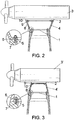
- the interposition is foreseen between these elements of a reel (4-4') embodied as a metal body with a frustoconical configuration, divergent in the case of figure 2 , i.e., when the diameter of the means of securing the turbine (3) is greater than the diameter of the coronation (1) of the tower, or convergent as in the case of figure 3 , when the diameter of the means of securing the turbine (3') is smaller than the diameter of the coronation (1) of the tower.
- the reel (4, 4') presents a lower circular base with a diameter matching that of the coronation (1) of the tower, with an inner and lower peripheral flange (5) having orifices (6) for passage of the corresponding securing bolts (7), while the upper diameter of the reel as shown in the figures will be different for each turbine type, according to the specific needs of each case, also including an inner and upper peripheral flange (8) having orifices (9) for passage of the corresponding securing bolts (10).
- a second adaptor 11
- a wedge-like profile i.e., with a varying thickness
- the variation in width between the ends thereof obviously depends on the change in the inclination of the blades that must be achieved, said crown being provided with a plurality of evenly distributed orifice (12).
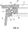
- This adaptor is placed between the articulation means (13) of the turbine and the general structure thereof, introducing the corresponding bolts (14) thereby allowing maintaining the distance between the blade tips and the tower regardless of the orientation of the rotation axis thereof.
- one or more segments can be added at the bottom of the tower.
Landscapes
- Engineering & Computer Science (AREA)
- Architecture (AREA)
- Chemical & Material Sciences (AREA)
- Life Sciences & Earth Sciences (AREA)
- Sustainable Energy (AREA)
- Civil Engineering (AREA)
- Structural Engineering (AREA)
- Sustainable Development (AREA)
- Combustion & Propulsion (AREA)
- Mechanical Engineering (AREA)
- General Engineering & Computer Science (AREA)
- Wood Science & Technology (AREA)
- Materials Engineering (AREA)
- Wind Motors (AREA)
Abstract
Description
- The present invention relates to a wind turbine tower of those meant to support the corresponding wind turbine as a means for generating electrical energy.
- The object of the invention is to provide a multi-platform or multi-turbine tower that assists in cost savings in the manufacture of these types of structures, such that the same does not need to be designed specifically for each type of turbine present in the market but, using a single tower model, such as with a 120 meter shaft, the tower can be perfectly used for a plurality of turbines of various manufacturers, such that this polyvalent use allows obtaining greatly significant economic savings in the long run.
- In the field of practical application of the invention, that of concrete wind turbine towers, hitherto each wind tower was designed specifically for the turbine model to be installed therein, resulting in extremely high costs that are obviously worth minimizing.
- Although invention patent P201430312 by the applicant describes a structure based on frustoconical sections of different inclinations, which allows obtaining from straight segments a broken profile as close as possible to the theoretical optimum curved profile intended for the tower, thereby reducing the cost of manufacture of these type of structures, this structure continues requiring a specific design of each tower for each turbine.
- The present invention bases its features on obtaining a tower from sections that define segments for said frustoconical configuration tower, with the special particularity that from specific features of the design of the tower it is possible for the tower to have an extremely versatile nature, which is value for supporting with full safety guarantees various types of turbines available in the market with the interposition of one or possibly two simple adaptors.
- For this purpose, in view of the need to provide a tower with a shaft height on the order of 120 meters, it has been foreseen that the tower design consists in a load envelope according to the specifications of each of the manufacturers.
- The geometrical fit is based on parameters such as the maximum diameter admitted at blade tip and the frequency range to prevent the tower from entering in resonance and causing the amplification of the acting loads.
- However, two alternative ways of obtaining the tower have been foreseen:
- Complying in all the sections with the condition of maximum diameter admitted at blade tip (a known parameter);
- Complying in most sections with the condition of maximum diameter admitted at blade tip, such that when this cannot be achieved, a minimum conning angle is applied.
- In either case, the division into sections of the tower is defined by the transportation criteria, preferably limiting the maximum section weight to 55 tons, its maximum width to 4.5 meters, and its maximum length to 24 meters.
- With regard to the frequency range, the data corresponding to the various types of turbines are used to calculate upper and lower limits thereof.
- Similarly, it is necessary to check decompression at the tips, which conditions prestressing on site, indirectly controlling the distance between securing points.
- At the same time, it is necessary to check the minimum prestress level at the segments prestressed in the workshop, check flexion and flushing at the joints, which conditions passive assembly at joints.
- In view of this structure a multi-platform or multi-turbine tower is obtained that can support the loads of many different market-available turbines; as each turbine has securing bolts arranged annularly, with a diameter that is different for different turbines, it is necessary to adapt the diameter of the upper end or coronation of the tower to the diameter of the lower securing means of the turbine, for which the inclusion has been foreseen of adaptors or reels, embodied as metal bodies with a preferably frustoconical configuration, which can converge or diverge in an upward sense so that in every case a lower circular base is defined with a diameter matching that of the tower coronation, with a peripheral flange having orifices for passage of the corresponding securing bolts, while the upper diameter of the reel will be different for each turbine type, according to the specific needs of each case, and can be greater or smaller than the diameter of the tower coronation, consequently determining the inverted or non-inverted arrangement of the frustoconical configuration of the reel.
- Naturally, at the upper base of the reel a peripheral flange will also be defined having the corresponding securing orifices for bolting the turbine.
- Obviously, the generatrix of the adaptor does not have to be precisely straight to obtain the same end, such that it could be curved or broken, without this affecting the essence of the invention as this would merely correspond to design alternatives.
- Although the geometrical study of the tower has considered the blade tip issue -the maximum diameter at the blade tip- there may be turbine models in which the blades have insufficient separation, such that because of the configuration of the tower the ends of the blade during rotation follow a trajectory that is too close to the tower at said point (as the tower cross-section increases in a downward sense). For this reason, the existence of a second type of adaptor meant to slightly modify the position of the horizontal shaft of the generator moving it to a position insignificantly inclined, such that the sweeping plane of the blades passes from a vertical position to a slightly inclined position, and therefore the blade tips will be separated from the tower.
- This second adapter consists in a type of circular crown, with a wedge-like profile, i.e. with a varying thickness, the variation in width between the ends thereof obviously depends on the change in the inclination of the blades that must be achieved.
- By way of example, a change in 1 degree of the verticality plane of the blades would increase by more than one meter the separation of the tips of said blades with respect to the tower at said tip area for blades measuring 60 meters.
- Since the turbines can turn to adapt to different wind directions, this wedge-like element is placed between the hinging means of the turbine and the general structure of the turbine, thereby maintaining the distance between the blade tips and the tower regardless of the orientation of the axis of rotation of the blades.
- In this way it is possible to adapt many different types of turbines to a single tower which, although oversized and possibly more expensive to manufacture per unit, represents great economic savings as it is not necessary to manufacture a specific tower for each turbine.
- To complete the description made below and in order to aid a better understanding of the characteristics of the invention, a set of drawings is accompanied as an integral part of the description with reference to a preferred example practical embodiment of the invention where, for purpose of illustration only and in a nonlimiting sense, the following is shown:
- Figure 1
- shows a representation of a comparison of geometries of different towers needed to support different types of turbines, from which a load envelope is obtained for the new tower that allows admitting with complete certainty all the different types of turbines, for a height of 120 meters; this profile is represented by a thickness line, with six sections marked into which the tower body is divided, although this tower could optionally be divided into any number of sections.
- Figure 2
- shows an enlarged side view and cross sectional view of the means for adapting and securing the tower to a first turbine type, where the lower radius of the turbine is greater than that of the coronation of the multi-platform or multiturbine tower.
- Figure 3
- shows a view similar to
figure 2 , in this case corresponding to a second type of turbine where the lower radius of the turbine is smaller than that of the coronation of the multi-platform or multi-turbine tower. - Figure 4
- shows a plan view of the second type of adaptors foreseen for the multi-platform or multi-turbine tower meant to increase the distance between the blade tips and the tower.
- Figure 5
- shows a cross section view of the adaptor of the previous figure along the A-B line.
- Figure 6
- shows an enlarged cross section of the form of installing the adapter of
figures 4 and 5 in a wind turbine. -
Figure 1 represents in thinner lines the theoretical profiles for obtaining different types of towers of 120 meters, according to the specifications of a number of turbines. - As shown in thicker lines, the improvements of the invention allow obtaining a profile for the tower that geometrically matches the load envelope obtained by superimposing the aforementioned theoretical profiles.
- In the present example a tower is selected obtained from six segments although, as indicated above, the tower can also be obtained from any number of segments.
- For this tower of invariable dimensions, a fixed upper diameter is defined at its end or coronation (1) which obviously does not have to match the various diameters of the lower securing means (2) that are defined in correspondence with the lower face of each turbine (3).
- For this purpose, the interposition is foreseen between these elements of a reel (4-4') embodied as a metal body with a frustoconical configuration, divergent in the case of
figure 2 , i.e., when the diameter of the means of securing the turbine (3) is greater than the diameter of the coronation (1) of the tower, or convergent as in the case offigure 3 , when the diameter of the means of securing the turbine (3') is smaller than the diameter of the coronation (1) of the tower. - Consequently, the reel (4, 4') presents a lower circular base with a diameter matching that of the coronation (1) of the tower, with an inner and lower peripheral flange (5) having orifices (6) for passage of the corresponding securing bolts (7), while the upper diameter of the reel as shown in the figures will be different for each turbine type, according to the specific needs of each case, also including an inner and upper peripheral flange (8) having orifices (9) for passage of the corresponding securing bolts (10).
- As indicated above, although the tower has been designed to consider the separation of the blade tips from the tower there may be cases in which a turbine model presents an insufficient separation, the inclusion has been foreseen of a second adaptor (11), as shown in
figures 4 and 5 , consisting in a type of circular crown, with a wedge-like profile, i.e., with a varying thickness, the variation in width between the ends thereof obviously depends on the change in the inclination of the blades that must be achieved, said crown being provided with a plurality of evenly distributed orifice (12). - This adaptor is placed between the articulation means (13) of the turbine and the general structure thereof, introducing the corresponding bolts (14) thereby allowing maintaining the distance between the blade tips and the tower regardless of the orientation of the rotation axis thereof.
- For heights less than 120 meters it is possible to reduce the height of the lower segment of the tower or even to eliminate said segment or more segments depending on the desired tower height.
- Similarly, for greater heights one or more segments can be added at the bottom of the tower.
Claims (3)
- Multi-platform wind tower, of the type consisting of a series of vertical segments of concrete sections obtained by joining two or more concrete segments, and wherein the various segments participating in the tower present a frustoconical configuration, with a different inclination for each segment, such that a broken profile is obtained that is as close as possible to the theoretical curved optimum profile that designed for the tower, characterized in that the profile of the tower geometrically corresponds to a load envelope obtained by superposing the theoretical profiles of corresponding towers designed specifically for a plurality of different turbines, such that in order to secure the various turbines to the top end or coronation (1) of the tower a number of adaptors or reels (4, 4') have been foreseen embodied as a metal body, the profile of which can change according to different lines of design, where the lower base thereof has a diameter matching the invariable diameter of the upper end or coronation (1) of the tower and the upper base has the specific diameter of the turbine to install, there adaptors being provided with means for securing them to the tower coronation and the turbine, at their upper and lower bases.
- Multi-platform wind tower, according to claim 1, characterized in that the reels (4,4') include corresponding lower (5) and upper (8) flanges in correspondence with the lower and upper bases thereof, provided with orifices (6-9) for the passage of the corresponding bots securing them to the tower coronation and the turbine articulation means.
- Multi-platform wind tower, according to claim 1, characterized in that when the separation between the free end of the turbine blade tips and the tower itself is not suitable, the inclusion has been foreseen of a second type of adaptor (11) embodied as a circular crown with a variable thickness, defining a type of wedge, provided with a plurality of evenly distributed orifices (12) and that is placed between the articulation means (13) of the turbine and the general structure thereof, by means of the corresponding bolts (14).
Applications Claiming Priority (2)
| Application Number | Priority Date | Filing Date | Title |
|---|---|---|---|
| ES201531514A ES2552363B1 (en) | 2015-10-22 | 2015-10-22 | Multi-platform wind tower |
| PCT/ES2016/070749 WO2017068225A1 (en) | 2015-10-22 | 2016-10-24 | Multi-platform wind turbine tower |
Publications (3)
| Publication Number | Publication Date |
|---|---|
| EP3364024A1 true EP3364024A1 (en) | 2018-08-22 |
| EP3364024A4 EP3364024A4 (en) | 2019-07-17 |
| EP3364024B1 EP3364024B1 (en) | 2022-10-05 |
Family
ID=54601439
Family Applications (1)
| Application Number | Title | Priority Date | Filing Date |
|---|---|---|---|
| EP16856979.6A Active EP3364024B1 (en) | 2015-10-22 | 2016-10-24 | Multi-platform wind turbine tower |
Country Status (6)
| Country | Link |
|---|---|
| US (1) | US10221835B2 (en) |
| EP (1) | EP3364024B1 (en) |
| BR (1) | BR112018007843B1 (en) |
| ES (2) | ES2552363B1 (en) |
| MA (1) | MA43357A (en) |
| WO (1) | WO2017068225A1 (en) |
Families Citing this family (3)
| Publication number | Priority date | Publication date | Assignee | Title |
|---|---|---|---|---|
| US10570889B2 (en) * | 2018-04-23 | 2020-02-25 | General Electric Company | Adaptor for wind turbine refurbishment and associated methods |
| EP3788259A4 (en) * | 2018-04-30 | 2021-12-15 | General Electric Company | PROCEDURE FOR RENOVATING WIND TURBINES |
| EP3771825A1 (en) * | 2019-08-01 | 2021-02-03 | Siemens Gamesa Renewable Energy A/S | Wind turbine and method for constructing a wind turbine |
Family Cites Families (19)
| Publication number | Priority date | Publication date | Assignee | Title |
|---|---|---|---|---|
| US3846042A (en) * | 1973-09-07 | 1974-11-05 | Smith H | Pedestal mounted wind generator |
| US4045147A (en) * | 1976-05-10 | 1977-08-30 | Ssp Agricultural Equipment, Inc. | Tiltable wind machine for use on variable terrain |
| US5354175A (en) * | 1992-03-16 | 1994-10-11 | Northern Power Systems, Inc. | Wind turbine rotor hub and teeter joint |
| US20020157328A1 (en) * | 2001-02-06 | 2002-10-31 | Bruce Holder | Shim made from a plastic material and an associated method of adjusting the spatial relationship between a first surface and a second surface |
| US7431567B1 (en) * | 2003-05-30 | 2008-10-07 | Northern Power Systems Inc. | Wind turbine having a direct-drive drivetrain |
| DE10336998A1 (en) * | 2003-08-12 | 2005-03-10 | Noi Immobilien Und Vermoegensv | Wind energy utilization system for generating power has tower with streamlined rotatable adapter at top carrying prolate spheroid- shaped gondola with hub carrying windmill blades |
| JP2006200400A (en) * | 2005-01-19 | 2006-08-03 | Fuji Heavy Ind Ltd | Horizontal axis windmill |
| DE102009017586A1 (en) * | 2009-04-19 | 2010-10-28 | Timber Tower Gmbh | Tower for a wind turbine |
| ES2378199B1 (en) * | 2009-06-24 | 2013-06-05 | Acciona Windpower S.A. | SYSTEM OF UNION OF A GONDOLA WITH THE TOWER OF CONCRETE OF AN AEROGENERATOR. |
| US8464990B2 (en) * | 2009-10-01 | 2013-06-18 | Idea Labs, Inc. | Pole mounted rotation platform and wind power generator |
| US8277184B2 (en) * | 2010-04-22 | 2012-10-02 | General Electric Company | Tilt adjustment system |
| US20120023860A1 (en) * | 2011-05-25 | 2012-02-02 | General Electric Company | Adapter Configuration for a Wind Tower Lattice Structure |
| US20120025538A1 (en) * | 2011-06-20 | 2012-02-02 | Michael James Luneau | Unitary support frame for use in wind turbines and methods for fabricating same |
| DE102011090194B4 (en) * | 2011-12-30 | 2013-12-05 | Rolf J. Werner | Tower-shaped structure |
| GB201214381D0 (en) * | 2012-08-13 | 2012-09-26 | Offshore Design Engineering Ltd | Plated tower transition piece |
| DE102013226536A1 (en) * | 2013-12-18 | 2015-06-18 | Wobben Properties Gmbh | Arrangement with a concrete foundation and a tower and method for erecting a tower |
| ES2548297B9 (en) * | 2014-02-18 | 2021-01-15 | Inneo Torres Sl | Prefabricated footing for wind towers |
| ES2545038B1 (en) * | 2014-03-07 | 2016-04-26 | Inneo Torres, S.L. | Construction system for wind towers |
| US9982659B1 (en) * | 2017-02-03 | 2018-05-29 | General Electric Company | Methods for refurbishing wind turbines |
-
2015
- 2015-10-22 ES ES201531514A patent/ES2552363B1/en not_active Expired - Fee Related
-
2016
- 2016-10-24 BR BR112018007843-3A patent/BR112018007843B1/en active IP Right Grant
- 2016-10-24 WO PCT/ES2016/070749 patent/WO2017068225A1/en not_active Ceased
- 2016-10-24 MA MA43357A patent/MA43357A/en unknown
- 2016-10-24 ES ES16856979T patent/ES2934736T3/en active Active
- 2016-10-24 US US15/769,802 patent/US10221835B2/en active Active
- 2016-10-24 EP EP16856979.6A patent/EP3364024B1/en active Active
Also Published As
| Publication number | Publication date |
|---|---|
| ES2552363B1 (en) | 2016-05-23 |
| US20180313333A1 (en) | 2018-11-01 |
| BR112018007843B1 (en) | 2023-01-24 |
| EP3364024B1 (en) | 2022-10-05 |
| WO2017068225A1 (en) | 2017-04-27 |
| EP3364024A4 (en) | 2019-07-17 |
| US10221835B2 (en) | 2019-03-05 |
| ES2552363A1 (en) | 2015-11-27 |
| ES2934736T3 (en) | 2023-02-24 |
| BR112018007843A2 (en) | 2019-01-08 |
| MA43357A (en) | 2018-08-22 |
Similar Documents
| Publication | Publication Date | Title |
|---|---|---|
| US10704220B2 (en) | Arrangement with a concrete foundation and a tower and a method for erecting a tower | |
| CN103807117B (en) | Gantry assembling system for wind turbine and method thereof | |
| EP2374966A1 (en) | Method of building a hybrid tower for a wind generator | |
| US10012005B2 (en) | Crane system incorporated into a tower | |
| EP3364024B1 (en) | Multi-platform wind turbine tower | |
| EP2846040A1 (en) | Tower assembly for a wind turbine installation | |
| EP2525093A2 (en) | Wind turbine with tower support system and associated method of construction | |
| US11136780B2 (en) | Annular bracket for externally loading a tower segment, external loading system of a hybrid tower, tower section of a hybrid tower, hybrid tower, wind turbine, and assembly method of an external loading system for a hybrid tower | |
| EP2955299B9 (en) | System and erection method for towers made of concrete | |
| US10260284B2 (en) | Ladder installation for equipment tower | |
| US20180202418A1 (en) | Methods for erecting or dismantling a multirotor wind turbine | |
| CA2823814C (en) | Mounting assembly and method to erect in sections an annular tower for wind or heliostatic power generators in an energy farm | |
| EP3855017A1 (en) | Building structure comprising a vortex generator to reduce induced vibrations | |
| US10337194B2 (en) | Work platform system configured for use structure with internal cavity, and related methods of assembly and use | |
| DK2837819T3 (en) | Method of mounting a rotor blade | |
| JP2020527211A (en) | Wind Turbine Steel Tower Ring Segments and Methods | |
| EP3168390A1 (en) | Structure for a wind turbine tower | |
| JP2022088251A (en) | Disassembly method of tower type wind turbine generator system | |
| EP3967872A1 (en) | Mounting structure for supporting a tower sector | |
| US20240392743A1 (en) | Wind turbine blade, ladder support assembly, wind turbine and method for providing access to the interior of a hollow blade of a wind turbine | |
| KR101516166B1 (en) | Tower support structure | |
| KR102563882B1 (en) | Installing device for wind turbine tower and installing method thereof | |
| JP7736323B2 (en) | Elevating scaffolding device for tower-like structures | |
| PL70596Y1 (en) | Wind turbine with vertical rotation of the rotor axis |
Legal Events
| Date | Code | Title | Description |
|---|---|---|---|
| STAA | Information on the status of an ep patent application or granted ep patent |
Free format text: STATUS: THE INTERNATIONAL PUBLICATION HAS BEEN MADE |
|
| PUAI | Public reference made under article 153(3) epc to a published international application that has entered the european phase |
Free format text: ORIGINAL CODE: 0009012 |
|
| STAA | Information on the status of an ep patent application or granted ep patent |
Free format text: STATUS: REQUEST FOR EXAMINATION WAS MADE |
|
| 17P | Request for examination filed |
Effective date: 20180518 |
|
| AK | Designated contracting states |
Kind code of ref document: A1 Designated state(s): AL AT BE BG CH CY CZ DE DK EE ES FI FR GB GR HR HU IE IS IT LI LT LU LV MC MK MT NL NO PL PT RO RS SE SI SK SM TR |
|
| AX | Request for extension of the european patent |
Extension state: BA ME |
|
| RIN1 | Information on inventor provided before grant (corrected) |
Inventor name: JIMENO ALONSO, JORGE ENRIQUE Inventor name: LLEYDA DIONIS, JOSE LUIS |
|
| DAX | Request for extension of the european patent (deleted) | ||
| RAV | Requested validation state of the european patent: fee paid |
Extension state: MA Effective date: 20180518 |
|
| A4 | Supplementary search report drawn up and despatched |
Effective date: 20190618 |
|
| RIC1 | Information provided on ipc code assigned before grant |
Ipc: F03D 13/20 20160101AFI20190612BHEP |
|
| STAA | Information on the status of an ep patent application or granted ep patent |
Free format text: STATUS: EXAMINATION IS IN PROGRESS |
|
| 17Q | First examination report despatched |
Effective date: 20200327 |
|
| GRAP | Despatch of communication of intention to grant a patent |
Free format text: ORIGINAL CODE: EPIDOSNIGR1 |
|
| STAA | Information on the status of an ep patent application or granted ep patent |
Free format text: STATUS: GRANT OF PATENT IS INTENDED |
|
| INTG | Intention to grant announced |
Effective date: 20220401 |
|
| GRAS | Grant fee paid |
Free format text: ORIGINAL CODE: EPIDOSNIGR3 |
|
| GRAA | (expected) grant |
Free format text: ORIGINAL CODE: 0009210 |
|
| STAA | Information on the status of an ep patent application or granted ep patent |
Free format text: STATUS: THE PATENT HAS BEEN GRANTED |
|
| AK | Designated contracting states |
Kind code of ref document: B1 Designated state(s): AL AT BE BG CH CY CZ DE DK EE ES FI FR GB GR HR HU IE IS IT LI LT LU LV MC MK MT NL NO PL PT RO RS SE SI SK SM TR |
|
| REG | Reference to a national code |
Ref country code: GB Ref legal event code: FG4D |
|
| REG | Reference to a national code |
Ref country code: CH Ref legal event code: EP |
|
| REG | Reference to a national code |
Ref country code: AT Ref legal event code: REF Ref document number: 1522894 Country of ref document: AT Kind code of ref document: T Effective date: 20221015 |
|
| REG | Reference to a national code |
Ref country code: DE Ref legal event code: R096 Ref document number: 602016075514 Country of ref document: DE |
|
| REG | Reference to a national code |
Ref country code: IE Ref legal event code: FG4D |
|
| REG | Reference to a national code |
Ref country code: LT Ref legal event code: MG9D |
|
| REG | Reference to a national code |
Ref country code: NL Ref legal event code: MP Effective date: 20221005 |
|
| REG | Reference to a national code |
Ref country code: ES Ref legal event code: FG2A Ref document number: 2934736 Country of ref document: ES Kind code of ref document: T3 Effective date: 20230224 |
|
| REG | Reference to a national code |
Ref country code: AT Ref legal event code: MK05 Ref document number: 1522894 Country of ref document: AT Kind code of ref document: T Effective date: 20221005 |
|
| PG25 | Lapsed in a contracting state [announced via postgrant information from national office to epo] |
Ref country code: NL Free format text: LAPSE BECAUSE OF FAILURE TO SUBMIT A TRANSLATION OF THE DESCRIPTION OR TO PAY THE FEE WITHIN THE PRESCRIBED TIME-LIMIT Effective date: 20221005 |
|
| PG25 | Lapsed in a contracting state [announced via postgrant information from national office to epo] |
Ref country code: SE Free format text: LAPSE BECAUSE OF FAILURE TO SUBMIT A TRANSLATION OF THE DESCRIPTION OR TO PAY THE FEE WITHIN THE PRESCRIBED TIME-LIMIT Effective date: 20221005 Ref country code: PT Free format text: LAPSE BECAUSE OF FAILURE TO SUBMIT A TRANSLATION OF THE DESCRIPTION OR TO PAY THE FEE WITHIN THE PRESCRIBED TIME-LIMIT Effective date: 20230206 Ref country code: NO Free format text: LAPSE BECAUSE OF FAILURE TO SUBMIT A TRANSLATION OF THE DESCRIPTION OR TO PAY THE FEE WITHIN THE PRESCRIBED TIME-LIMIT Effective date: 20230105 Ref country code: LT Free format text: LAPSE BECAUSE OF FAILURE TO SUBMIT A TRANSLATION OF THE DESCRIPTION OR TO PAY THE FEE WITHIN THE PRESCRIBED TIME-LIMIT Effective date: 20221005 Ref country code: FI Free format text: LAPSE BECAUSE OF FAILURE TO SUBMIT A TRANSLATION OF THE DESCRIPTION OR TO PAY THE FEE WITHIN THE PRESCRIBED TIME-LIMIT Effective date: 20221005 Ref country code: AT Free format text: LAPSE BECAUSE OF FAILURE TO SUBMIT A TRANSLATION OF THE DESCRIPTION OR TO PAY THE FEE WITHIN THE PRESCRIBED TIME-LIMIT Effective date: 20221005 |
|
| PG25 | Lapsed in a contracting state [announced via postgrant information from national office to epo] |
Ref country code: RS Free format text: LAPSE BECAUSE OF FAILURE TO SUBMIT A TRANSLATION OF THE DESCRIPTION OR TO PAY THE FEE WITHIN THE PRESCRIBED TIME-LIMIT Effective date: 20221005 Ref country code: PL Free format text: LAPSE BECAUSE OF FAILURE TO SUBMIT A TRANSLATION OF THE DESCRIPTION OR TO PAY THE FEE WITHIN THE PRESCRIBED TIME-LIMIT Effective date: 20221005 Ref country code: LV Free format text: LAPSE BECAUSE OF FAILURE TO SUBMIT A TRANSLATION OF THE DESCRIPTION OR TO PAY THE FEE WITHIN THE PRESCRIBED TIME-LIMIT Effective date: 20221005 Ref country code: IS Free format text: LAPSE BECAUSE OF FAILURE TO SUBMIT A TRANSLATION OF THE DESCRIPTION OR TO PAY THE FEE WITHIN THE PRESCRIBED TIME-LIMIT Effective date: 20230205 Ref country code: HR Free format text: LAPSE BECAUSE OF FAILURE TO SUBMIT A TRANSLATION OF THE DESCRIPTION OR TO PAY THE FEE WITHIN THE PRESCRIBED TIME-LIMIT Effective date: 20221005 Ref country code: GR Free format text: LAPSE BECAUSE OF FAILURE TO SUBMIT A TRANSLATION OF THE DESCRIPTION OR TO PAY THE FEE WITHIN THE PRESCRIBED TIME-LIMIT Effective date: 20230106 |
|
| REG | Reference to a national code |
Ref country code: CH Ref legal event code: PL |
|
| REG | Reference to a national code |
Ref country code: BE Ref legal event code: MM Effective date: 20221031 |
|
| P01 | Opt-out of the competence of the unified patent court (upc) registered |
Effective date: 20230523 |
|
| PG25 | Lapsed in a contracting state [announced via postgrant information from national office to epo] |
Ref country code: LU Free format text: LAPSE BECAUSE OF NON-PAYMENT OF DUE FEES Effective date: 20221024 |
|
| REG | Reference to a national code |
Ref country code: DE Ref legal event code: R097 Ref document number: 602016075514 Country of ref document: DE |
|
| PG25 | Lapsed in a contracting state [announced via postgrant information from national office to epo] |
Ref country code: SM Free format text: LAPSE BECAUSE OF FAILURE TO SUBMIT A TRANSLATION OF THE DESCRIPTION OR TO PAY THE FEE WITHIN THE PRESCRIBED TIME-LIMIT Effective date: 20221005 Ref country code: RO Free format text: LAPSE BECAUSE OF FAILURE TO SUBMIT A TRANSLATION OF THE DESCRIPTION OR TO PAY THE FEE WITHIN THE PRESCRIBED TIME-LIMIT Effective date: 20221005 Ref country code: MC Free format text: LAPSE BECAUSE OF FAILURE TO SUBMIT A TRANSLATION OF THE DESCRIPTION OR TO PAY THE FEE WITHIN THE PRESCRIBED TIME-LIMIT Effective date: 20221005 Ref country code: LI Free format text: LAPSE BECAUSE OF NON-PAYMENT OF DUE FEES Effective date: 20221031 Ref country code: EE Free format text: LAPSE BECAUSE OF FAILURE TO SUBMIT A TRANSLATION OF THE DESCRIPTION OR TO PAY THE FEE WITHIN THE PRESCRIBED TIME-LIMIT Effective date: 20221005 Ref country code: DK Free format text: LAPSE BECAUSE OF FAILURE TO SUBMIT A TRANSLATION OF THE DESCRIPTION OR TO PAY THE FEE WITHIN THE PRESCRIBED TIME-LIMIT Effective date: 20221005 Ref country code: CZ Free format text: LAPSE BECAUSE OF FAILURE TO SUBMIT A TRANSLATION OF THE DESCRIPTION OR TO PAY THE FEE WITHIN THE PRESCRIBED TIME-LIMIT Effective date: 20221005 Ref country code: CH Free format text: LAPSE BECAUSE OF NON-PAYMENT OF DUE FEES Effective date: 20221031 |
|
| PLBE | No opposition filed within time limit |
Free format text: ORIGINAL CODE: 0009261 |
|
| STAA | Information on the status of an ep patent application or granted ep patent |
Free format text: STATUS: NO OPPOSITION FILED WITHIN TIME LIMIT |
|
| PG25 | Lapsed in a contracting state [announced via postgrant information from national office to epo] |
Ref country code: SK Free format text: LAPSE BECAUSE OF FAILURE TO SUBMIT A TRANSLATION OF THE DESCRIPTION OR TO PAY THE FEE WITHIN THE PRESCRIBED TIME-LIMIT Effective date: 20221005 Ref country code: AL Free format text: LAPSE BECAUSE OF FAILURE TO SUBMIT A TRANSLATION OF THE DESCRIPTION OR TO PAY THE FEE WITHIN THE PRESCRIBED TIME-LIMIT Effective date: 20221005 |
|
| 26N | No opposition filed |
Effective date: 20230706 |
|
| GBPC | Gb: european patent ceased through non-payment of renewal fee |
Effective date: 20230105 |
|
| PG25 | Lapsed in a contracting state [announced via postgrant information from national office to epo] |
Ref country code: BE Free format text: LAPSE BECAUSE OF NON-PAYMENT OF DUE FEES Effective date: 20221031 |
|
| PG25 | Lapsed in a contracting state [announced via postgrant information from national office to epo] |
Ref country code: IE Free format text: LAPSE BECAUSE OF NON-PAYMENT OF DUE FEES Effective date: 20221024 Ref country code: GB Free format text: LAPSE BECAUSE OF NON-PAYMENT OF DUE FEES Effective date: 20230105 |
|
| PG25 | Lapsed in a contracting state [announced via postgrant information from national office to epo] |
Ref country code: SI Free format text: LAPSE BECAUSE OF FAILURE TO SUBMIT A TRANSLATION OF THE DESCRIPTION OR TO PAY THE FEE WITHIN THE PRESCRIBED TIME-LIMIT Effective date: 20221005 Ref country code: FR Free format text: LAPSE BECAUSE OF NON-PAYMENT OF DUE FEES Effective date: 20221205 |
|
| PGFP | Annual fee paid to national office [announced via postgrant information from national office to epo] |
Ref country code: ES Payment date: 20231102 Year of fee payment: 8 |
|
| PGFP | Annual fee paid to national office [announced via postgrant information from national office to epo] |
Ref country code: TR Payment date: 20231005 Year of fee payment: 8 |
|
| PG25 | Lapsed in a contracting state [announced via postgrant information from national office to epo] |
Ref country code: HU Free format text: LAPSE BECAUSE OF FAILURE TO SUBMIT A TRANSLATION OF THE DESCRIPTION OR TO PAY THE FEE WITHIN THE PRESCRIBED TIME-LIMIT; INVALID AB INITIO Effective date: 20161024 |
|
| PG25 | Lapsed in a contracting state [announced via postgrant information from national office to epo] |
Ref country code: CY Free format text: LAPSE BECAUSE OF FAILURE TO SUBMIT A TRANSLATION OF THE DESCRIPTION OR TO PAY THE FEE WITHIN THE PRESCRIBED TIME-LIMIT Effective date: 20221005 |
|
| PGFP | Annual fee paid to national office [announced via postgrant information from national office to epo] |
Ref country code: DE Payment date: 20240102 Year of fee payment: 8 |
|
| PG25 | Lapsed in a contracting state [announced via postgrant information from national office to epo] |
Ref country code: MK Free format text: LAPSE BECAUSE OF FAILURE TO SUBMIT A TRANSLATION OF THE DESCRIPTION OR TO PAY THE FEE WITHIN THE PRESCRIBED TIME-LIMIT Effective date: 20221005 Ref country code: IT Free format text: LAPSE BECAUSE OF FAILURE TO SUBMIT A TRANSLATION OF THE DESCRIPTION OR TO PAY THE FEE WITHIN THE PRESCRIBED TIME-LIMIT Effective date: 20221005 |
|
| PG25 | Lapsed in a contracting state [announced via postgrant information from national office to epo] |
Ref country code: BG Free format text: LAPSE BECAUSE OF FAILURE TO SUBMIT A TRANSLATION OF THE DESCRIPTION OR TO PAY THE FEE WITHIN THE PRESCRIBED TIME-LIMIT Effective date: 20221005 |
|
| PG25 | Lapsed in a contracting state [announced via postgrant information from national office to epo] |
Ref country code: MT Free format text: LAPSE BECAUSE OF FAILURE TO SUBMIT A TRANSLATION OF THE DESCRIPTION OR TO PAY THE FEE WITHIN THE PRESCRIBED TIME-LIMIT Effective date: 20221005 |
|
| REG | Reference to a national code |
Ref country code: DE Ref legal event code: R119 Ref document number: 602016075514 Country of ref document: DE |
|
| PG25 | Lapsed in a contracting state [announced via postgrant information from national office to epo] |
Ref country code: DE Free format text: LAPSE BECAUSE OF NON-PAYMENT OF DUE FEES Effective date: 20250501 |
|
| VS25 | Lapsed in a validation state [announced via postgrant information from nat. office to epo] |
Ref country code: MA Free format text: FAILURE TO ELECT DOMICILE IN THE NATIONAL COUNTRY Effective date: 20230106 |
|
| REG | Reference to a national code |
Ref country code: ES Ref legal event code: FD2A Effective date: 20251203 |
|
| PG25 | Lapsed in a contracting state [announced via postgrant information from national office to epo] |
Ref country code: ES Free format text: LAPSE BECAUSE OF NON-PAYMENT OF DUE FEES Effective date: 20241025 |
|
| VS25 | Lapsed in a validation state [announced via postgrant information from nat. office to epo] |
Ref country code: MA Free format text: LAPSE BECAUSE OF FAILURE TO SUBMIT A TRANSLATION OF THE DESCRIPTION OR TO PAY THE FEE WITHIN THE PRESCRIBED TIME-LIMIT Effective date: 20221005 |