EP3363983A1 - Vacuum insulated glazing unit - Google Patents
Vacuum insulated glazing unit Download PDFInfo
- Publication number
- EP3363983A1 EP3363983A1 EP18156478.2A EP18156478A EP3363983A1 EP 3363983 A1 EP3363983 A1 EP 3363983A1 EP 18156478 A EP18156478 A EP 18156478A EP 3363983 A1 EP3363983 A1 EP 3363983A1
- Authority
- EP
- European Patent Office
- Prior art keywords
- evacuation
- cavity
- heating
- cup
- housing wall
- Prior art date
- Legal status (The legal status is an assumption and is not a legal conclusion. Google has not performed a legal analysis and makes no representation as to the accuracy of the status listed.)
- Granted
Links
Images



Classifications
-
- E—FIXED CONSTRUCTIONS
- E06—DOORS, WINDOWS, SHUTTERS, OR ROLLER BLINDS IN GENERAL; LADDERS
- E06B—FIXED OR MOVABLE CLOSURES FOR OPENINGS IN BUILDINGS, VEHICLES, FENCES OR LIKE ENCLOSURES IN GENERAL, e.g. DOORS, WINDOWS, BLINDS, GATES
- E06B3/00—Window sashes, door leaves, or like elements for closing wall or like openings; Layout of fixed or moving closures, e.g. windows in wall or like openings; Features of rigidly-mounted outer frames relating to the mounting of wing frames
- E06B3/66—Units comprising two or more parallel glass or like panes permanently secured together
- E06B3/6612—Evacuated glazing units
-
- E—FIXED CONSTRUCTIONS
- E06—DOORS, WINDOWS, SHUTTERS, OR ROLLER BLINDS IN GENERAL; LADDERS
- E06B—FIXED OR MOVABLE CLOSURES FOR OPENINGS IN BUILDINGS, VEHICLES, FENCES OR LIKE ENCLOSURES IN GENERAL, e.g. DOORS, WINDOWS, BLINDS, GATES
- E06B3/00—Window sashes, door leaves, or like elements for closing wall or like openings; Layout of fixed or moving closures, e.g. windows in wall or like openings; Features of rigidly-mounted outer frames relating to the mounting of wing frames
- E06B3/66—Units comprising two or more parallel glass or like panes permanently secured together
- E06B3/673—Assembling the units
- E06B3/67326—Assembling spacer elements with the panes
- E06B3/67334—Assembling spacer elements with the panes by soldering; Preparing the panes therefor
-
- E—FIXED CONSTRUCTIONS
- E06—DOORS, WINDOWS, SHUTTERS, OR ROLLER BLINDS IN GENERAL; LADDERS
- E06B—FIXED OR MOVABLE CLOSURES FOR OPENINGS IN BUILDINGS, VEHICLES, FENCES OR LIKE ENCLOSURES IN GENERAL, e.g. DOORS, WINDOWS, BLINDS, GATES
- E06B3/00—Window sashes, door leaves, or like elements for closing wall or like openings; Layout of fixed or moving closures, e.g. windows in wall or like openings; Features of rigidly-mounted outer frames relating to the mounting of wing frames
- E06B3/66—Units comprising two or more parallel glass or like panes permanently secured together
- E06B3/673—Assembling the units
- E06B3/67339—Working the edges of already assembled units
- E06B3/6736—Heat treatment
-
- E—FIXED CONSTRUCTIONS
- E06—DOORS, WINDOWS, SHUTTERS, OR ROLLER BLINDS IN GENERAL; LADDERS
- E06B—FIXED OR MOVABLE CLOSURES FOR OPENINGS IN BUILDINGS, VEHICLES, FENCES OR LIKE ENCLOSURES IN GENERAL, e.g. DOORS, WINDOWS, BLINDS, GATES
- E06B3/00—Window sashes, door leaves, or like elements for closing wall or like openings; Layout of fixed or moving closures, e.g. windows in wall or like openings; Features of rigidly-mounted outer frames relating to the mounting of wing frames
- E06B3/66—Units comprising two or more parallel glass or like panes permanently secured together
- E06B3/677—Evacuating or filling the gap between the panes ; Equilibration of inside and outside pressure; Preventing condensation in the gap between the panes; Cleaning the gap between the panes
- E06B3/6775—Evacuating or filling the gap during assembly
-
- Y—GENERAL TAGGING OF NEW TECHNOLOGICAL DEVELOPMENTS; GENERAL TAGGING OF CROSS-SECTIONAL TECHNOLOGIES SPANNING OVER SEVERAL SECTIONS OF THE IPC; TECHNICAL SUBJECTS COVERED BY FORMER USPC CROSS-REFERENCE ART COLLECTIONS [XRACs] AND DIGESTS
- Y02—TECHNOLOGIES OR APPLICATIONS FOR MITIGATION OR ADAPTATION AGAINST CLIMATE CHANGE
- Y02A—TECHNOLOGIES FOR ADAPTATION TO CLIMATE CHANGE
- Y02A30/00—Adapting or protecting infrastructure or their operation
- Y02A30/24—Structural elements or technologies for improving thermal insulation
- Y02A30/249—Glazing, e.g. vacuum glazing
-
- Y—GENERAL TAGGING OF NEW TECHNOLOGICAL DEVELOPMENTS; GENERAL TAGGING OF CROSS-SECTIONAL TECHNOLOGIES SPANNING OVER SEVERAL SECTIONS OF THE IPC; TECHNICAL SUBJECTS COVERED BY FORMER USPC CROSS-REFERENCE ART COLLECTIONS [XRACs] AND DIGESTS
- Y02—TECHNOLOGIES OR APPLICATIONS FOR MITIGATION OR ADAPTATION AGAINST CLIMATE CHANGE
- Y02B—CLIMATE CHANGE MITIGATION TECHNOLOGIES RELATED TO BUILDINGS, e.g. HOUSING, HOUSE APPLIANCES OR RELATED END-USER APPLICATIONS
- Y02B80/00—Architectural or constructional elements improving the thermal performance of buildings
- Y02B80/22—Glazing, e.g. vaccum glazing
Definitions
- the present invention relates to an arrangement for producing vacuum insulated glazing (VIG) unit and an evacuation cup suitable for such use as well as a method therefore.
- VIP vacuum insulated glazing
- VIG vacuum insulated glazing
- WO 00/29703 it is disclosed to situate a glass tube in the evacuation hole and provide a seal between the tube and the edge of the evacuation hole by means of a soldering material which is softened in a general heating of the VIG unit to provide a gas tight seal around the tube. Afterwards, an evacuation cup is placed over the tube and the void is evacuated. A metal coil inside the evacuation cup and enclosing the tip of the glass tube is electrically heated to melt the tip of the tube and thereby provide a sealing of the void.
- An evacuation cup for evacuating of a VIG unit is disclosed in US 2015/047394 , wherein a heating element is arranged movably inside the evacuation cup so that a sealing sheet can be fixed to the glass pane of the VIG unit by means of heating a solder material between the sealing sheet and the glass pane and thus sealing off the evacuation hole.
- the present inventors have found that it is advantageous to provide a more uniform or homogeneous heating of the part of the glass pane containing the evacuation hole and possibly a soldering material arranged around the evacuation hole, in particular for the reason of preventing larger temperature gradients in the glass pane between the part covered by the evacuation cup and the remaining part and for avoiding excessive locale temperatures of the glass pane under the evacuation cup, which may be harmful the durability of the glass pane, in particular when the glass pane is made from tempered glass, where the tempering of the glass may be influenced by excessive temperatures.
- the use of evacuation cups with heating sources distributed along the perimeter of the inner cavity of the evacuation cup has turned out to be advantageous for these reasons and have further advantages, which will be apparent from the following.
- an evacuation cup for providing a vacuum to a vacuum insulated glazing (VIG) unit comprising a void enclosed between two glass panes, wherein an evacuation hole is provided through one of the glass panes, the evacuation cup comprising
- the heat source of the first heating arrangement is not a single point source of heat, such as a single electrical resistance heater placed inside the housing wall of the evacuation cup at one point, but comprises one or more heat sources distributed along the perimeter of the first cavity, so that a more uniform or homogeneous heating is sought to be achieved.
- a heating arrangement can be said to be arranged distributedly if any plane being perpendicular to the plane of the first opening of the first cavity and containing a centreline of the evacuation cup would split the cup in two parts each being heated by the heating arrangement.
- Such first heating arrangement can preferably be arranged to heat the housing wall at positions distributed substantially evenly along the perimeter of the first cavity.
- the first heating arrangement may in one example comprise at least two electrical heating elements extending substantially perpendicularly to the plane of the first opening, preferably at least three such heating elements and such as four heating elements.
- the first heating arrangement comprises at least one ring-shaped electrical heating element enclosing the first cavity.
- the ring-shaped electrical heating element extends in a preferred example substantially parallel to the plane of the first opening.
- the first heating arrangement By arranging the first heating arrangement to heat the housing wall distributedly along the perimeter of the first cavity there may obtained an infrared heating of a soldering material, such as a soldering material containing a low-temperature melting glass frit, surrounding the evacuation hole, which heating is substantially homogeneous about an axis extending outward from the evacuation hole.
- a soldering material such as a soldering material containing a low-temperature melting glass frit
- Such heating of a soldering material may be performed prior to the actual evacuation of the void of the VIG unit for reaching a vacuum in order to form a gas tight seal around an evacuation tube extending from the evacuation hole or after the evacuation to reach a vacuum in the void so as to seal off the evacuation hole by means of a soldering material.
- the plane first land defines the edge of the housing wall that in contact with the outer surface of the first glass pane of the VIG unit, either directly or with a seal or gasket in between, will form a substantially hermetic connection that will allow a vacuum to be created in the void of the VIG unit by evacuating the first cavity of the evacuation cup.
- the arrangement may further comprising a control arrangement for controlling the operation of the first heating arrangement, in particular so as to heat the housing wall of the evacuation cup to a second temperature by means of the first heating arrangement, the second temperature being at least 5° C, preferably at least 8° C higher, such as at least 12° C higher, than the temperature of the air surrounding the outside of the evacuation cup, i.e. the temperature of the air inside e.g. a furnace the arrangement is situated within.
- the first heating arrangement may compensate for the temporal lacking of the temperature inside the evacuation cup and thus of the part of the first glass pane covered by the evacuation cup with respect to the air temperature of a furnace which the arrangement is situated within during preparation of the VIG unit.
- Such control of the second temperature being higher than the first temperature may in particular be employed during softening of a soldering material surrounding an evacuation tube extending from the evacuation hole to a flowing state in order to form an air tight seal.
- the heating element(s) of the first heating arrangement is/are in a preferred example situated at least partly inside the housing wall, such as completely inside the housing wall.
- the first heating arrangement may be situated on the evacuation cup but outside of the housing wall and heat said wall from the outside by means of e.g. conduction heating between the two and/or infrared heating, or the first heating arrangement may comprise other means for radiation heating, such as microwave heating or laser light sources.
- such means of radiation heating of the first heating arrangement may not be connected physically to the evacuation cup but instead be arranged externally in e.g. a furnace.
- the first opening if the first cavity is preferably substantially circular in shape, so that the first plane land encloses a substantially circular first opening.
- Each evacuation cup may in a particular preferred example further comprise a second plane land enclosing the first plane land and defining a second cavity within the housing wall with a second opening situated between the first plane land and the second plane land, and a second conduit connecting the second cavity and the outside of the housing wall.
- an evacuation pump is connected to the second conduit so as to lower the pressure inside the second cavity, which reduces the possible leakage from the exterior into the first cavity of the evacuation cup during evacuation of the void.
- the first plane land and the second plane land are of concentric annular shape.
- the largest width of the evacuation cups in the plane of the first plane land is 50 millimetres or less, preferably 45 millimetres or less.
- the arrangement further comprises a second heating arrangement for heating a distal tip of a tube extending from the evacuation hole so as to seal it off.
- the tube typically made from glass, is melted at the distal tip by means of the second heating arrangement after evacuation of the void of the VIG unit so as to seal it off and maintain the vacuum inside the void.
- the second heating arrangement comprises preferably a second heating element placed inside the first cavity of each evacuation cup, such as a ceramic heating element, preferably a silicon nitride and/or aluminium nitride ceramic heater or alternatively a heating coil made from tungsten.
- a ceramic heating element preferably a silicon nitride and/or aluminium nitride ceramic heater or alternatively a heating coil made from tungsten.
- the second heating arrangement may
- the control arrangement may furthermore is arranged to control the operation of the second heating arrangement.
- the arrangement may furthermore comprise at least one temperature sensor arranged in each evacuation cup for measuring a temperature and providing an output accordingly to the control arrangement.
- the sensor or sensors may be arranged to measuring the temperature of the housing wall, of the air inside the cavity of the evacuation cup or of the first pane of the VIG unit.
- the present invention relates to an arrangement for providing a vacuum to vacuum insulated glazing (VIG) units each comprising a void enclosed between two glass panes, wherein an evacuation hole is provided through one of the glass panes, the arrangement comprising an evacuation cup for each VIG unit, each evacuation cup comprising a housing wall, a first cavity within the housing wall arranged to be in fluid communication with the evacuation hole of the VIG unit by means of a first opening of the first cavity, a first plane land enclosing the first opening, a first conduit through the housing wall and in fluid communication with the first cavity, the arrangement further comprising for each evacuation cup a separate first heating arrangement placed outside of the first cavity of the evacuation cup, the first heating arrangement being arranged for heating the housing wall distributedly along the perimeter of the first cavity.
- VIP vacuum to vacuum insulated glazing
- the evacuation cup according to the second aspect of the present invention may comprise the features discussed previously with respect to the arrangement according to the first aspect of the present invention.
- a third aspect of the present invention relates to a method for providing a vacuum to a vacuum insulated glazing (VIG) unit comprising a void enclosed between two glass panes, wherein an evacuation hole is provided through a first of the glass panes, the method comprising the steps of
- the present invention relates to a method for providing a vacuum to a vacuum insulated glazing (VIG) unit comprising a void enclosed between two glass panes, wherein an evacuation hole is provided through a first of the glass panes (2a), the method comprising the steps of
- the first heating arrangement may compensate for the temporal lacking of the temperature inside the evacuation cup and thus of the part of the first glass pane covered by the evacuation cup with respect to the air temperature of a furnace which the arrangement is situated within during preparation of the VIG unit.
- Such control of the second temperature being higher than the first temperature may in particular be employed during softening of a soldering material surrounding an evacuation tube extending from the evacuation hole to a flowing state in order to form an air tight seal.
- the method may also comprising the heating of the housing wall of the evacuation cup prior to the temperature of the air inside the furnace reaching its goal temperature, i.e. the first temperature.
- the method may further comprise the step of maintaining the air temperature of the furnace at said first temperature while the housing wall is maintained at said second temperature for at least for 5 minutes, preferably at least for 10 minutes, so as to heat a soldering material surrounding the evacuation hole.
- the soldering material is preferably heated to a condition where it flows so that an air tight seal is formed.
- the formation of the seal may be conducted prior to the evacuation of the void to a vacuum, in which case a tube is provided extending from the evacuation opening and the seal is formed between the outer surface of the tube and the outer surface of the first glass pane so that the only gas passage between the void and the first cavity of the evacuation cup is through the tube.
- the soldering material is heated after the evacuation of the void is conducted so as to seal off the evacuation hole.
- the evacuation of the void is preferably carried out when the soldering material surrounding the evacuation hole is in a non-flowing condition.
- the soldering material may in specific examples be heated to a higher temperature than necessary to reach the flowing condition of the soldering material so as to perform a heat treatment of the soldering material, such as a partial crystallization of the soldering material.
- the temperature may e.g. be temperature 20-50° C higher than the temperature to reach the flowing condition, where the soldering material will flow out and bond with the surface of the first pane.
- the temperature of the soldering material will in such case typically be in the range of 400 to 440° C.
- the soldering material comprises preferably a low-melting temperature glass solder frit, more preferred a lead-free glass solder frit.
- the housing wall of the evacuation cup is heated so that the temperature of the first glass pane covered by the first cavity of the evacuation cup is substantially the same as the temperature of the first glass pane that is not covered by the evacuation cup, i.e. preferably with a deviation between the temperatures within 5° C, preferably within 3° C.
- This step is preferably performed when the air temperature of the furnace has reached T1.
- the method may further comprise the step of heating a distal tip of a tube extending from the evacuation hole by means of a second heating arrangement so as to seal it off.
- the method according to the third aspect of the present invention may be carried out with an arrangement and/or an evacuation cup as discussed previously with respect to the first aspect and the second aspect of the present invention.
- an evacuation cup for providing a vacuum to a vacuum insulated glazing (VIG) unit comprising a void enclosed between two glass panes, wherein an evacuation hole is provided through one of the glass panes, the evacuation cup comprising a housing wall, a first cavity within the housing wall arranged to be in fluid communication with the evacuation hole of the VIG unit by means of a first opening of the first cavity, a first plane land enclosing the first opening, a first conduit through the housing wall and in fluid communication with the first cavity, a first heating arrangement comprising electrical heating element or elements being arranged inside the first cavity of the evacuation cup and distributedly along the perimeter of the first cavity, and a second heating arrangement placed inside the first cavity for heating a distal tip of a tube extending from the evacuation hole so as to seal it off.
- VIP vacuum insulated glazing
- the first heating element inside the first cavity of the evacuation cup distributedly along the perimeter of the first cavity to provide a more uniform or homogeneous heating of the part of the glass pane containing the evacuation hole and possibly a soldering material arranged around the evacuation hole may be achieved as previously discussed.
- the heating element or elements of the first heating arrangement is/are a ceramic heating element, preferably a silicon nitride and/or aluminium nitride ceramic heater. However, e.g. tungsten may also be used as material for the heating element or elements.
- the evacuation cup according to the fourth aspect of the present invention may further comprising a control arrangement for controlling the operation of the first heating arrangement so as to heat the air in the first cavity of the evacuation cup by means of the first heating arrangement to the temperature of the air surrounding the outside of the evacuation cup.
- the deviation between the temperatures is preferably within 5° C, more preferably within 3° C.
- the first heating arrangement is preferably distributed substantially evenly along the perimeter of the first cavity.
- the first heating arrangement may in one example of the present invention comprise at least two electrical heating elements extending substantially perpendicularly to the plane of the first opening, preferably at least three such heating elements, such as four such heating elements.
- the first heating arrangement comprises at least one ring-shaped electrical heating element enclosing the first cavity.
- the ring-shaped electrical heating element extends preferably substantially parallel to the plane of the first opening.
- a fifth aspect of the present invention relates to a method for providing a vacuum to a vacuum insulated glazing (VIG) unit comprising a void enclosed between two glass panes, wherein an evacuation hole is provided through a first of the glass panes, the method comprising the steps of
- the first cavity of the evacuation cup is preferably heated by means of the first heating arrangement so that a soldering material surrounding the evacuation hole is heated to a condition where it flows.
- the soldering material may in a preferred example of the method according to the fifth aspect of the present invention be heated after the evacuation of the void is conducted so as to seal off the evacuation hole.
- said evacuation of the void is carried out when the soldering material surrounding the evacuation hole is in a non-flowing condition.
- the soldering material may furthermore be heated to a higher temperature than to reach the flowing condition of the soldering material so as to perform a heat treatment of the soldering material, such as to a temperature 20-50° C higher than the temperature to reach the flowing condition, where the soldering material will flow out and bond with the surface of the first pane.
- the temperature of the soldering material will typically be in the range of 400 to 440° C.
- Said soldering material comprises preferably a low-melting temperature glass solder frit, in particular a lead-free glass solder frit.
- the first cavity of the evacuation cup is preferably heated so that the temperature of the first glass pane covered by the first cavity of the evacuation cup reaches substantially the same temperature as the temperature of the first glass pane that is not covered by the evacuation cup, the deviation between the temperatures is preferably within 5° C, more preferably within 3° C.
- the air of the interior of the furnace is heated according to a predefined profile of temperature and the first heating arrangement is operated to heat the first cavity of the evacuation cup so that the temperature of the air in the first cavity is substantially the same as the temperature (T1) of the air of the interior of the furnace, the deviation between the temperatures being preferably within 5° C, more preferably within 3° C.
- the second heating arrangement is preferably placed inside the first cavity, but may alternatively be placed externally to the evacuation cup and operate by means of e.g. microwave radiation or laser light.
- the second heating arrangement when arranged inside the first cavity may comprise a second heating element which is a ceramic heating element, preferably a silicon nitride and/or aluminium nitride ceramic heater.
- the second heating arrangement may comprise a heating coil of e.g. tungsten.
- the method of the fifth aspect of the present invention may be using the evacuation cup according to the fourth aspect of the present invention.
- each VIG unit 1 comprises a void 3 enclosed between two glass panes 2a, 2b and an evacuation hole 4 is provided through one of the glass panes 2a.
- a number of pillars 5 may be arranged between the glass panes 2a, 2b in order to maintain the separation of the glass panes 2a, 2b at a suitable distance providing optimum insulating effects, such as about 0.2 millimetres.
- a side seal 6 is arranged peripherally between the two glass panes 2a, 2b and enclosing the void 3 and a soldering frit material 7 is placed around the evacuation hole 4.
- Fig. 1-4 shows cross-sections of an arrangement according to examples of the invention.
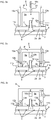
- the arrangement is placed in connection with a VIG unit 1 and the arrangement comprises an evacuation cup 8 comprising a housing wall 8' and a first cavity 9a within the housing wall 8' arranged to be in fluid communication with the evacuation hole 4 of the VIG unit 1 by means of a first opening 10a.
- the evacuation cup 8 further comprises a first plane land 11a enclosing the first opening 10a, and a first conduit 12a through the housing wall 8' and in fluid communication with the first cavity 9a.
- the arrangement also comprises for each evacuation cup 8 a separate first heating arrangement 13 placed outside of the first cavity 9a of the evacuation cup 8 and the first heating arrangement 13 is being arranged for heating the housing wall 8' distributedly along the perimeter of the first cavity 9a.
- a soldering frit material 7 placed around the evacuation hole 4 may be heated substantially uniformly by means of the first heating arrangement 13 via a substantially uniform heating of the housing wall 8'.
- the heating element(s) may be distributed symmetrically such that the axis of symmetry is an axis extending outward from the evacuation hole 4, and preferably perpendicular to the first opening 10a and/or the first plane land 11a. Additionally or alternatively the heating element(s) may be arranged symmetrically having one or more axis of symmetry in a plane parallel to first opening 10a and/or the first plane land 11 a.
- the housing wall 8' As the housing wall 8' is heated it will transfer heat towards the soldering frit material 7 and the first glass pane 2a covered by the evacuation cup 8.
- the thermal energy can be transferred by conduction, convection or radiation. Heat transfer by convection will be predominant when the first heating arrangement 13 is operated to heat the housing wall 8' prior to evacuation of the void 3 by heating up the air inside the first cavity 9a. Heat transfer by means of radiation will also occur as the hot housing wall 8' will become a source of radiation for irradiating the soldering frit material 7 preferably evenly from all sides of the evacuation cup 8 in a plane perpendicular to the first plane land 11a. This will in turn provide a dense and uniform frit seal.
- the first heating arrangement 13 may comprise a single or several heating elements, and the heating elements may be chosen from a group of different types such as IR radiation, microwave or laser radiation, induction, electrical and ceramic heaters.
- the housing wall 8' is made of metal durable at high temperatures and a good conductor of heat for the present invention, such as stainless steel.
- the evacuation cup 8 is of circular shape in a cross-section in a plane parallel to the glass panes 2a, 2b and enclosing an evacuation hole 4, which preferably is also of a circular shape.
- the diameter of the evacuation cup 8 measured parallel to the first plane land 11a is preferably no larger than 50 mm, such as 45 mm and provides a temperature change in a small region of the VIG unit 1, minimizing any possible reduction in overall strength of the glazing unit due to a temperature difference between first cavity 9a and the outside of the evacuation cup 8.
- the soldering frit material 7 may comprise an evacuation opening for evacuating the void 3 of the VIG unit 1 through the first conduit 12a via the first cavity 9a and the evacuation opening.
- the soldering frit material 7 surrounds a glass tube 14 which provides a pathway for the gas between the void 3 and the first cavity 9a. After evacuation of the void 3 the evacuation hole 4 is closed.
- the first heating arrangement 13 is configured to be operated to provide the necessary heat for the soldering frit material 7 to enter a flowing state and close off the evacuation hole 4 at pressures from atmospheric to vacuum pressures.
- a temperature sensor 15 is placed in the housing wall 8' as indicated in Fig. 1-4 .
- This sensor 15 measures the temperature of the housing wall 8' and is configured to send an output accordingly to a control arrangement 16 and/or the user of the system, which controls the temperature of the housing wall 8' based on the output by controlling the operation of the first heating arrangement 13.
- the sensor output may be used as an indirect measure of the temperature of the air inside the first cavity 9a and of the soldering frit material 7.
- the first heating arrangement 13 may be controlled through a proportional-integral-derivative (PID) controller system comprised in the control arrangement 16.
- the evacuation cup 8 may be provided with one or more temperature sensors for measuring the temperature of the air inside the first cavity 9a and/or the outer surface temperature of the first glass pane 2a inside the first cavity 9a and provide output accordingly to the control arrangement 16.
- Fig. 1a illustrates a cross-sectional view of an arrangement according to an example of the invention, where the arrangement comprises a first heating arrangement 13 having a number of electrical heating rods 13a, such as four heating rods, placed substantially inside the housing wall 8' of the evacuation cup 8.
- the heating rods 13a are positioned such that they extend substantially perpendicular to the first plane land 11a.
- the heating rods 13a are distributed along the perimeter of the first cavity 9a such that the first cavity 9a is heated from several portions of the housing wall 8', and substantially provides a uniform heating of the interior of the first cavity 9a.
- the heating rods 13a are placed outside the first cavity 9a and they are not directly exposed to the interior of the first cavity 9a.
- the heating rods 13a may be entirely embedded in the housing wall 8'. Heating of soldering frit material 7 placed around the evacuation hole 4 can be obtained using the first heating arrangement 13 which provides substantially uniform heating about an axis extending outward from the evacuation hole 4.
- Fig. 1b shows an arrangement having a first heating arrangement 13 placed outside of the first cavity 9a of the evacuation cup 8, outside the housing walls 8' of the evacuation cup 8 and externally to the evacuation cup 8 itself.
- the first heating arrangement 13 of this example comprises one or more radiation sources 13b which transfer heat to the housing wall 8' by means of radiation.
- the housing wall 8' is irradiated by suitable electromagnetic radiation, such as laser, microwave or IR radiation.
- the first heating arrangement 13 may comprise a single element 13b arranged such that it extends around the first cavity 9a and uniformly heats the first cavity 9a via the housing wall 8' around an axis extending outward from the evacuation hole 4.
- the heat generated in the housing wall 8' is preferably distributed within the housing wall 8' such that a substantially uniform heating of the soldering frit material 7 is obtained.
- the housing wall 8' of the evacuation cup 8 is made of a highly conductive material such as metal, preferably stainless steel.
- the radiation sources 13b are distributed evenly around the first cavity 9a, preferably in a symmetric pattern about an axis extending outward from the evacuation hole. In an aspect there may be four radiation sources 13b distributed evenly around the first cavity 9a.
- the first heating arrangement 13 comprises multiple heating elements 13c mounted on the evacuation cup 8 and placed near the outside surface of the housing wall 8' of the evacuation cup 8.
- the heating elements are in the present example electrical resistor heaters 13c.
- a thermal shield 17 is placed next to each resistor heater 13c, such that it reflects the thermal radiation generated by the electrical resistors 13c towards the housing wall 8' and so that the heat is confined to the nearby surroundings of the housing wall 8'.
- the electrical resistor heaters 13c are preferably placed distributed evenly around the housing wall 8', in order to provide a uniform heating of the first cavity 9a.
- the heaters 13c may be ring-shaped and enclosing the evacuation cup, such that the housing wall 8' and the ring-shaped resistor heaters are concentric. Accordingly, the thermal shield 17 may also be ring-shaped and concentric with the housing wall 8'.
- the electrical resistor heaters 13c are placed directly in connection with the outside surface of the evacuation cup 8, but they could alternatively be arranged at a distance from the housing wall 8' and solely heat the housing wall 8' by means of infrared (IR) radiation..
- IR infrared
- Fig. 1d shows an arrangement having a first heating arrangement 13 comprising an electrical heating element 13d shaped as a ring, which is embedded in the housing wall 8' of the evacuation cup 8 and surrounds the first cavity 9a.
- the extend of the ring-shaped heating element 13d can be seen in Fig. 1e which illustrates a cross-section of the evacuation cup 8 cut along the line A-A as indicated in Fig. 1d .
- Fig. 1e an opening for placement of the temperature sensor 15 is also indicated as well as the first conduit 12a.
- the ring-shaped heating element 13d is in the present example positioned such that it extends parallel to the first opening 10a of the evacuation cup 8 and thereby can provide heating of the first cavity 9a which is symmetric and uniform about an axis extending outward from the evacuation hole 4.
- the ring shaped heating element 13d is configured for heating the soldering frit material 7 via heating of the housing wall 8'.
- the housing wall 8' contribute to distributing the heat generated by the ring-shaped heating element 13d such that a large area of the first cavity 9a is affected by the heat generated by the ring-shaped heating element 13d.
- the ring-shaped heating element 13d is preferably positioned at a specific height within the housing wall 8' at which height, the heat generated by the ring-shaped heat element 13d is most efficiently transferred to the soldering frit material 7 and to the first glass pane 2a covered by the evacuation cup 8.
- the evacuation cup 8 may comprise more than one cavity.
- a second cavity 9b is shown in the housing wall 8'.
- the evacuation cup 8 comprises a first plane land 11a enclosing the first opening 10a of the first cavity 9a and a second plane 11b land enclosing the first plane land 11a and the second opening 10b of the second cavity 9b, additionally the first plane land 11a and second plane land 11b are arranged in a concentric configuration.
- the evacuation cup 8 is arranged on a VIG unit 1 such that the first plane land 11a and the second plane land 11b are in abutment with the outer surface of the first glass pane 2a.
- a sealing material may be provided between the plane lands 11a, 11b and the glass surface in order to promote a hermetic connection.
- a second cavity 9b with a second opening 10b is defined between the first plane land 11a and second plane land 11b .
- a second conduit 12b is in connection with the second cavity 9b for fluid communication between the second cavity 9b and the outside of the housing wall 8'.
- the second cavity 9b may have two purposes, a first purpose is to limit the leak from the outside of the housing wall 8' to the first cavity 9a during evacuation of the void 3 and a second purpose is to aid in maintaining the evacuation cup 8 in connection with the VIG unit 1 by creating a low pressure in the second cavity 9b prior to the evacuation of the first cavity 9a. Contaminants etc.
- first cavity 9a and the second cavity 9b are connected to separate pumps 18.
- FIG. 2a An example of an arrangement according to an example of the invention is shown in Fig. 2a .
- the arrangement comprises electrical heating rods 13a, a temperature sensor 15 and a first conduit 12a and a second conduit 12b in fluid connection with a first cavity 9a and a second cavity 9b.
- the second cavity 9b is preferably an annular cavity as illustrated in the cross section of evacuation cup 8 shown in Fig. 2b ; the cross-section is generated from the A-A cutting plane indicated in Fig. 2a .
- four electrical heating rods 13a are arranged symmetrically about an axis extending outward from the evacuation hole 4.
- the evacuation cup 8 comprises heat transfer capabilities sufficient for distributing the heat generated from the electrical heating rods 13a in the housing wall 8' such that temperature of the housing wall 8' becomes more uniform around the perimeter of the first cavity 9a.
- Fig. 2c shows a cross section of evacuation cup 8 shown in Fig. 2b , the cross-section is generated from the B-B cutting plane indicated in Fig. 2a .
- the cross-section illustrates the circular shape of the evacuation cup 8.
- the housing wall 8' is shown extending across the first cavity 9a and second cavity 9b and enclosing these.
- the evacuation cup 8 may comprise the first heating arrangement 13 and also a second heating arrangement 19.
- the arrangement comprises a first heating arrangement 13 and a second heating arrangement 19 and the VIG unit 1 is arranged with a glass tube 14 placed in the evacuation hole 4, through which tube 14 the void 3 can be evacuated.
- the frit soldering material 7 is arranged around the tube 14 and is heat-treated using the first heating arrangement 13 in order to create a hermetic seal between the tube 14 and the first glass pane 2a.
- the seal is preferably obtained prior to evacuation of the void 3 such that gas is evacuated through the tube 14 only. After the evacuation of the void 3 has been executed the tube 14 is sealed by heating the tip of the tube 14, thereby fully enclosing the void 3.
- the tube 14 is in the present examples sealed by heat provided by the second heating arrangement 19.
- the soldering frit material 7 is heated using electrical heating rods 13a embedded in the housing wall 8' and the tip of the tube 14 is heated using a second heating arrangement 19 comprising a radiation source 19a providing thermal radiation to the tube 14.
- the tube 14 is irradiated by suitable electromagnetic radiation, such as laser, microwave or IR radiation for a sufficient amount of time for melting the tip of the tube 14 and seal it such that no gas can transfer between the void 3 and the outside of the VIG unit 1.
- the radiation source is located outside the evacuation cup 8, and may not be in connection with the evacuation cup 8.
- a window 21 is provided in the housing wall 8' of the evacuation cup 8, which allows the radiation to be transmitted to the tip of the tube 14.
- Fig. 3b shows an arrangement having a second heating arrangement 19 comprising a heating element 19b positioned inside the first cavity 9a.
- the second heating arrangement 19 is placed in connection with housing wall 8' at a position above the tip of the tube 14.
- the second heating arrangement 19 may comprise a heat element 19b suitable for heating the tip of the tube 14 to approximately 900-1200 degrees Celsius, such as a tungsten coil or a ceramic heating element.
- the second heating arrangement 19 is configured to provide sufficient heating for the tip of the tube 14 at pressures from atmospheric to vacuum pressure.
- Fig. 3c A similar example to the arrangement shown in Fig. 3b is shown in Fig. 3c .
- the evacuation cup 8 comprises a first heating arrangement 13 having a ring-shaped electrical heating element13d instead of heating rods 13a.
- the ring-shaped electrical heating element 13d is positioned inside the housing wall 8' and above the second cavity 9b, but in one or more examples the second cavity 9b can also be at a position within the housing wall 8' which is closer to the outside surface of the housing wall 8', i.e. towards the outside of the evacuation cup 8, whereby the ring-shaped heat element 13d may be placed closer to the inside surface of the housing wall 8' towards the first cavity 9a.
- the ring-shaped heat element 13d can be positioned closer to the VIG unit 1 and the first plane land 11a.
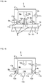
- Fig. 4a and Fig. 4b show two examples of an arrangement where both the first heating arrangement 13 and the second heating arrangement 19 are positioned inside the first cavity 9a.
- the second heating arrangement 19 may comprise a heat element 19b suitable for heating the tip of the tube 14 to approximately 900-1200 degrees Celsius, such as a tungsten coil or a ceramic heating element.
- a heat element 19b suitable for heating the tip of the tube 14 to approximately 900-1200 degrees Celsius, such as a tungsten coil or a ceramic heating element.
- the first heating arrangement 13 comprises a ring-shaped electrical heating element 13d, which may be place in close proximity to the soldering frit material 7 and around the soldering frit material 7 such that a large fraction of the heat generated by the ring-shaped heating element 13d is directly absorbed by the soldering frit material 7 and so that the soldering frit material 7 obtains substantially the same amount of thermal energy about an axis extending outward from the evacuation hole 4.
- the ring-shaped heating element 13d has an extent which is parallel to the first opening 10a of the evacuation cup 8. It may be placed in connection with the inside surface of the housing wall 8' or the first glass pane 2a.
- the first heating arrangement 13 comprises a ring-shaped electrical heating element 13d of slightly different shape and position as the rings-shaped electrical heating element 13d shown in Fig. 4a .
- the ring-shaped electrical heating element 13d is distributed along the perimeter of the first cavity 9a, and abutting a part of the inside surface of the housing wall 8'.
- the ring-shaped heating element 13d is in the present example attached to the inside surface of the housing wall 8', at a position such that it surrounds the soldering frit material 7. It may simultaneously heat the housing wall 8' and the soldering frit material 7.
- the heating of the housing wall 8' may in turn create a source of radiation for irradiating and heating the soldering frit material 7.
- the first heating arrangement 13 is configured to heat the housing wall 8' to a second temperature (T2) which is higher than a first temperature (T1) of the air surrounding the outside the evacuation cup 8.
- the housing wall 8' is configured such that an increase in temperature of the housing wall 8' provides an increase in temperature of the elements enclosed by the housing wall 8', such as the air inside the first cavity 9a, the soldering frit material 7 and the part of the first glass pane 2a covered by the evacuation cup 8.
- One purpose of the heating of the elements enclosed by the housing wall 8' is to compensate for the shielding effect of the housing wall 8' which causes the temperature of the elements inside the housing wall 8' to be heated with a time delay as compared to the air in the furnace and outside the housing wall 8'.
- the soldering frit material 7 and the first pane 2a inside the first cavity 9a are in one preferred embodiment heated to substantially the same temperature as the remaining part of the first glass pane 2a by heating the air inside the first cavity 9a to substantially the same temperature as the air surrounding the outside of the housing wall 8' of the evacuation cup 8 such that the soldering frit material 7 forms a hermetic seal, which is in a substantially non-flowing state when the evacuation of the void 3 to a vacuum state is to be initiated.
- the VIG unit 1 may be produced inside a furnace 20.
- the air surrounding the outside of the evacuation cup 8 may be heated to the first temperature (T1) by a furnace 20 and the first temperature (T1) may be utilized to soften soldering frit material between and around the periphery of the glass panes such that a side seal 6 is formed.
- the first temperature (T1) provided by the furnace 20 is preferably high enough, e.g. least 275 degrees Celsius, in order to efficiently vaporize any contaminants and to provide an optimal thermal cleaning process of the VIG unit 1 during the evacuation of the void 3.
- each VIG unit 1 is arranged with an arrangement according to one or more examples of the invention.
- the arrangements are in fluid connection with one or more evacuation pumps 18.
- the arrangements, and especially the first heating arrangement 13 and possible second heating arrangement 19 and additionally the temperature sensor 15 within the housing wall 8' are in communication with one or more control arrangements 16.
- the control arrangement 16 may be configured to adjust the temperature of the housing wall 8', such that the temperature of the air within first cavity 9a is the same or different from the air surrounding the evacuation cup 8.
- the temperature sensor 15 is configured to register the temperature in the evacuation cup 8 and to send an output accordingly to the control arrangement 16.
- the control arrangement 16 is configured to control the first heating arrangement 13 based on the output received from the temperature sensor 15.
- This feedback system such as a PID controller system, may be comprised in the control arrangement 16 for automatically controlling the temperatures of the housing wall 8' and indirectly also the first cavity 9a and the soldering frit material 7 according to predetermined temperature profiles for the VIG unit production, such as a predetermined temperature profile for producing a hermetic seal from the soldering frit material 7 provided around the evacuation hole 4.
- the control arrangement 16 may also configured to control the furnace 20 and the pumps 18.
- the evacuation cup 8 is placed on the first glass pane 2a such that the first plane land 11a is in connection with the first glass pane 2a, such that they are in abutment, preferably with a sealing material or gasket provided. If the evacuation cup 8 has a second plane lane 11b, this is also in abutment with the first glass pane 2a, or in connection with the first glass pane 2a via a seal or gasket.
- the second temperature (T2) is measured using a temperature sensor 15 which sends an output accordingly to the control arrangement 16 which in turn controls the first heating arrangement 13 based on the output received from the temperature sensor 15.
- the control of the first heating arrangement 16 may be done automatically based on the output.
- the control arrangement 16 may be configured to control the first heating arrangement 13 such that it follows a predetermined temperature profile.
- the first heating arrangement 13 may be set to heat the soldering frit material 7 to 350 degrees Celsius for 30 minutes and then thereafter heat to 390 degrees Celsius for 40 minutes.
- the soldering frit material 7 may be heated to a temperature which is 20-50 degrees Celsius higher than the temperature at which the soldering frit material 7 will flow. This higher temperature may be a temperature about 420 degrees Celsius.
- the soldering frit material 7 around the evacuation hole 4 is heat-treated separately from the side seal 6.
- the heat generated can be focused on the soldering frit material 7, such that e.g. the first glass pane 2a covered by the first cavity 9a of the evacuation cup 8 is only minimally affected by heated housing wall 8' .
- the soldering frit material 7 After heating the soldering frit material 7 to a flowing state and cooling it subsequently, the soldering frit material 7 is in a non-flowing state at which time it is safe to initiate the evacuation of the void 3 without compromising the efficiency of the seal provided by the soldering frit material 7. If the evacuation is initiated too soon, the soldering frit material 7 may become detached from the surfaces.
- the void 3 is evacuated by a pump 18, via the first conduit 12a and the first cavity 9a.
- the pressure to be reached inside the void 3 is preferably at least 10 -3 mbar.
- a tube 14 is provided in the evacuation hole 4, with the soldering frit material 7 placed between the outside of the tube 14 and the first glass pane 2a such that the void 3 may be evacuated via the tube 14.
- the evacuation hole 4 is closed by either heating the soldering frit material 7 such that it extends across the evacuation hole 4 or by sealing the tube 14.
- the second heating arrangement 19 may be moved towards the tube tip to provide a local heating of the tip of the tube 14.
Landscapes
- Engineering & Computer Science (AREA)
- Civil Engineering (AREA)
- Structural Engineering (AREA)
- Physics & Mathematics (AREA)
- Thermal Sciences (AREA)
- Joining Of Glass To Other Materials (AREA)
Abstract
Description
- The present invention relates to an arrangement for producing vacuum insulated glazing (VIG) unit and an evacuation cup suitable for such use as well as a method therefore.
- When producing vacuum insulated glazing (VIG) units it is known from the art to provide an evacuation cup to enclose an evacuation opening or hole in one of the glass panes constituting the VIG unit in order to evacuate the interior void of the VIG unit so as to create a vacuum with an insulating effect between the glass panes of the VIG unit. It is known in the art to apply heating to the interior of the evacuation cup in order to seal off the evacuation hole after evacuating the interior void of the VIG unit.
- In
WO 00/29703 - Another evacuation cup and the use thereof for evacuating a VIG unit is disclosed in
US 5,855,638 , wherein a heating coil situated external to the evacuation cup at one side thereof is applied to heat the cup after evacuation of the void of the VIG unit so as to soften a ball of a soldering material situated at the top of the evacuation hole so that it will plug the countersunk outer opening of the evacuation hole. - An evacuation cup for evacuating of a VIG unit is disclosed in
US 2015/047394 , wherein a heating element is arranged movably inside the evacuation cup so that a sealing sheet can be fixed to the glass pane of the VIG unit by means of heating a solder material between the sealing sheet and the glass pane and thus sealing off the evacuation hole. - The present inventors have found that it is advantageous to provide a more uniform or homogeneous heating of the part of the glass pane containing the evacuation hole and possibly a soldering material arranged around the evacuation hole, in particular for the reason of preventing larger temperature gradients in the glass pane between the part covered by the evacuation cup and the remaining part and for avoiding excessive locale temperatures of the glass pane under the evacuation cup, which may be harmful the durability of the glass pane, in particular when the glass pane is made from tempered glass, where the tempering of the glass may be influenced by excessive temperatures. The use of evacuation cups with heating sources distributed along the perimeter of the inner cavity of the evacuation cup has turned out to be advantageous for these reasons and have further advantages, which will be apparent from the following.
- In a first aspect of the present invention, it relates to an evacuation cup for providing a vacuum to a vacuum insulated glazing (VIG) unit comprising a void enclosed between two glass panes, wherein an evacuation hole is provided through one of the glass panes, the evacuation cup comprising
- a housing wall,
- a first cavity within the housing wall arranged to be in fluid communication with the evacuation hole of the VIG unit by means of a first opening of the first cavity,
- a first plane land enclosing the first opening,
- a first conduit through the housing wall and in fluid communication with the first cavity, and
- a first heating arrangement placed outside of the first cavity of the evacuation cup, the first heating arrangement being arranged for heating the housing wall distributedly along the perimeter of the first cavity.
- With the term "arranged distributedly" is herein understood that the heat source of the first heating arrangement is not a single point source of heat, such as a single electrical resistance heater placed inside the housing wall of the evacuation cup at one point, but comprises one or more heat sources distributed along the perimeter of the first cavity, so that a more uniform or homogeneous heating is sought to be achieved. A heating arrangement can be said to be arranged distributedly if any plane being perpendicular to the plane of the first opening of the first cavity and containing a centreline of the evacuation cup would split the cup in two parts each being heated by the heating arrangement.
- Such first heating arrangement can preferably be arranged to heat the housing wall at positions distributed substantially evenly along the perimeter of the first cavity. The first heating arrangement may in one example comprise at least two electrical heating elements extending substantially perpendicularly to the plane of the first opening, preferably at least three such heating elements and such as four heating elements.
- In another example, the first heating arrangement comprises at least one ring-shaped electrical heating element enclosing the first cavity. The ring-shaped electrical heating element extends in a preferred example substantially parallel to the plane of the first opening.
- By arranging the first heating arrangement to heat the housing wall distributedly along the perimeter of the first cavity there may obtained an infrared heating of a soldering material, such as a soldering material containing a low-temperature melting glass frit, surrounding the evacuation hole, which heating is substantially homogeneous about an axis extending outward from the evacuation hole. Such heating of a soldering material may be performed prior to the actual evacuation of the void of the VIG unit for reaching a vacuum in order to form a gas tight seal around an evacuation tube extending from the evacuation hole or after the evacuation to reach a vacuum in the void so as to seal off the evacuation hole by means of a soldering material. In both cases, it is advantageous to provide a homogeneous heating from the inside of the housing wall to the soldering material so that an excessive heating of a part of the soldering material and/or a part of the first glass pane of the VIG unit under the evacuation cup due to uneven heating is prevented.
- The plane first land defines the edge of the housing wall that in contact with the outer surface of the first glass pane of the VIG unit, either directly or with a seal or gasket in between, will form a substantially hermetic connection that will allow a vacuum to be created in the void of the VIG unit by evacuating the first cavity of the evacuation cup.
- The arrangement may further comprising a control arrangement for controlling the operation of the first heating arrangement, in particular so as to heat the housing wall of the evacuation cup to a second temperature by means of the first heating arrangement, the second temperature being at least 5° C, preferably at least 8° C higher, such as at least 12° C higher, than the temperature of the air surrounding the outside of the evacuation cup, i.e. the temperature of the air inside e.g. a furnace the arrangement is situated within. Hereby, the first heating arrangement may compensate for the temporal lacking of the temperature inside the evacuation cup and thus of the part of the first glass pane covered by the evacuation cup with respect to the air temperature of a furnace which the arrangement is situated within during preparation of the VIG unit. Such control of the second temperature being higher than the first temperature may in particular be employed during softening of a soldering material surrounding an evacuation tube extending from the evacuation hole to a flowing state in order to form an air tight seal.
- The heating element(s) of the first heating arrangement is/are in a preferred example situated at least partly inside the housing wall, such as completely inside the housing wall. However, in other examples of the present invention, the first heating arrangement may be situated on the evacuation cup but outside of the housing wall and heat said wall from the outside by means of e.g. conduction heating between the two and/or infrared heating, or the first heating arrangement may comprise other means for radiation heating, such as microwave heating or laser light sources. In a further example according to the present invention, such means of radiation heating of the first heating arrangement may not be connected physically to the evacuation cup but instead be arranged externally in e.g. a furnace.
- The first opening if the first cavity is preferably substantially circular in shape, so that the first plane land encloses a substantially circular first opening.
- Each evacuation cup may in a particular preferred example further comprise a second plane land enclosing the first plane land and defining a second cavity within the housing wall with a second opening situated between the first plane land and the second plane land, and a second conduit connecting the second cavity and the outside of the housing wall. During operation of the evacuation cup, an evacuation pump is connected to the second conduit so as to lower the pressure inside the second cavity, which reduces the possible leakage from the exterior into the first cavity of the evacuation cup during evacuation of the void. Hereby, the hermetic connection between the first glass pane and the evacuation cup is improved. It is furthermore preferred that the first plane land and the second plane land are of concentric annular shape.
- The largest width of the evacuation cups in the plane of the first plane land is 50 millimetres or less, preferably 45 millimetres or less.
- In yet a preferred example, the arrangement further comprises a second heating arrangement for heating a distal tip of a tube extending from the evacuation hole so as to seal it off. The tube, typically made from glass, is melted at the distal tip by means of the second heating arrangement after evacuation of the void of the VIG unit so as to seal it off and maintain the vacuum inside the void.
- The second heating arrangement comprises preferably a second heating element placed inside the first cavity of each evacuation cup, such as a ceramic heating element, preferably a silicon nitride and/or aluminium nitride ceramic heater or alternatively a heating coil made from tungsten. Alternatively, the second heating arrangement may
- The control arrangement may furthermore is arranged to control the operation of the second heating arrangement.
- The arrangement may furthermore comprise at least one temperature sensor arranged in each evacuation cup for measuring a temperature and providing an output accordingly to the control arrangement. The sensor or sensors may be arranged to measuring the temperature of the housing wall, of the air inside the cavity of the evacuation cup or of the first pane of the VIG unit.
- In a second aspect of the present invention, the present invention relates to an arrangement for providing a vacuum to vacuum insulated glazing (VIG) units each comprising a void enclosed between two glass panes, wherein an evacuation hole is provided through one of the glass panes, the arrangement comprising an evacuation cup for each VIG unit, each evacuation cup comprising a housing wall, a first cavity within the housing wall arranged to be in fluid communication with the evacuation hole of the VIG unit by means of a first opening of the first cavity, a first plane land enclosing the first opening, a first conduit through the housing wall and in fluid communication with the first cavity, the arrangement further comprising for each evacuation cup a separate first heating arrangement placed outside of the first cavity of the evacuation cup, the first heating arrangement being arranged for heating the housing wall distributedly along the perimeter of the first cavity.
- The evacuation cup according to the second aspect of the present invention may comprise the features discussed previously with respect to the arrangement according to the first aspect of the present invention.
- In a third aspect of the present invention, it relates to a method for providing a vacuum to a vacuum insulated glazing (VIG) unit comprising a void enclosed between two glass panes, wherein an evacuation hole is provided through a first of the glass panes, the method comprising the steps of
- arranging an evacuation cup on the first glass pane so that the evacuation hole is in fluid communication with a first cavity provided in a housing wall of the evacuation cup by means of a first opening of the first cavity,
- placing the VIG unit in a furnace,
- heating the air of the interior of the furnace with the VIG unit to a first temperature (T1),
- heating the housing wall of the evacuation cup to a second temperature by means of a first heating arrangement placed outside the first cavity of the evacuation cup while the air temperature of the furnace is at said first temperature, the second temperature being at least 5° C higher, preferably at least 8° C higher, such as at least 12° C than the first temperature,
and - evacuating the void by pumping out the first cavity of the evacuation cup through a first conduit provided through the housing wall and in fluid communication with the first cavity.
- In particular, the present invention relates to a method for providing a vacuum to a vacuum insulated glazing (VIG) unit comprising a void enclosed between two glass panes, wherein an evacuation hole is provided through a first of the glass panes (2a), the method comprising the steps of
- arranging an evacuation cup on the first glass pane so that the evacuation hole is in fluid communication with a first cavity provided in a housing wall of the evacuation cup by means of a first opening of the first cavity, wherein said evacuation cup is an evacuation cup as disclosed herein in accordance with the first aspect of the present invention,
- placing the VIG unit (1) in a furnace (20), and
- heating the air of the interior of the furnace (20) with the VIG unit (1) to a first temperature (T1).
- Hereby, the first heating arrangement may compensate for the temporal lacking of the temperature inside the evacuation cup and thus of the part of the first glass pane covered by the evacuation cup with respect to the air temperature of a furnace which the arrangement is situated within during preparation of the VIG unit. Such control of the second temperature being higher than the first temperature may in particular be employed during softening of a soldering material surrounding an evacuation tube extending from the evacuation hole to a flowing state in order to form an air tight seal.
- The method may also comprising the heating of the housing wall of the evacuation cup prior to the temperature of the air inside the furnace reaching its goal temperature, i.e. the first temperature.
- The method may further comprise the step of maintaining the air temperature of the furnace at said first temperature while the housing wall is maintained at said second temperature for at least for 5 minutes, preferably at least for 10 minutes, so as to heat a soldering material surrounding the evacuation hole.
- The soldering material is preferably heated to a condition where it flows so that an air tight seal is formed. The formation of the seal may be conducted prior to the evacuation of the void to a vacuum, in which case a tube is provided extending from the evacuation opening and the seal is formed between the outer surface of the tube and the outer surface of the first glass pane so that the only gas passage between the void and the first cavity of the evacuation cup is through the tube. Alternatively, the soldering material is heated after the evacuation of the void is conducted so as to seal off the evacuation hole.
- The evacuation of the void is preferably carried out when the soldering material surrounding the evacuation hole is in a non-flowing condition.
- The soldering material may in specific examples be heated to a higher temperature than necessary to reach the flowing condition of the soldering material so as to perform a heat treatment of the soldering material, such as a partial crystallization of the soldering material. The temperature may e.g. be temperature 20-50° C higher than the temperature to reach the flowing condition, where the soldering material will flow out and bond with the surface of the first pane. The temperature of the soldering material will in such case typically be in the range of 400 to 440° C.
- The soldering material comprises preferably a low-melting temperature glass solder frit, more preferred a lead-free glass solder frit.
- In a particular example of the method, the housing wall of the evacuation cup is heated so that the temperature of the first glass pane covered by the first cavity of the evacuation cup is substantially the same as the temperature of the first glass pane that is not covered by the evacuation cup, i.e. preferably with a deviation between the temperatures within 5° C, preferably within 3° C. This step is preferably performed when the air temperature of the furnace has reached T1.
- The method may further comprise the step of heating a distal tip of a tube extending from the evacuation hole by means of a second heating arrangement so as to seal it off.
- The method according to the third aspect of the present invention may be carried out with an arrangement and/or an evacuation cup as discussed previously with respect to the first aspect and the second aspect of the present invention.
- According to a fourth aspect of the present invention, it relates to an evacuation cup for providing a vacuum to a vacuum insulated glazing (VIG) unit comprising a void enclosed between two glass panes, wherein an evacuation hole is provided through one of the glass panes, the evacuation cup comprising a housing wall, a first cavity within the housing wall arranged to be in fluid communication with the evacuation hole of the VIG unit by means of a first opening of the first cavity, a first plane land enclosing the first opening, a first conduit through the housing wall and in fluid communication with the first cavity, a first heating arrangement comprising electrical heating element or elements being arranged inside the first cavity of the evacuation cup and distributedly along the perimeter of the first cavity, and a second heating arrangement placed inside the first cavity for heating a distal tip of a tube extending from the evacuation hole so as to seal it off.
- By arranging the first heating element inside the first cavity of the evacuation cup distributedly along the perimeter of the first cavity to provide a more uniform or homogeneous heating of the part of the glass pane containing the evacuation hole and possibly a soldering material arranged around the evacuation hole may be achieved as previously discussed.
- The heating element or elements of the first heating arrangement is/are a ceramic heating element, preferably a silicon nitride and/or aluminium nitride ceramic heater. However, e.g. tungsten may also be used as material for the heating element or elements.
- The evacuation cup according to the fourth aspect of the present invention may further comprising a control arrangement for controlling the operation of the first heating arrangement so as to heat the air in the first cavity of the evacuation cup by means of the first heating arrangement to the temperature of the air surrounding the outside of the evacuation cup. The deviation between the temperatures is preferably within 5° C, more preferably within 3° C.
- The first heating arrangement is preferably distributed substantially evenly along the perimeter of the first cavity.
- The first heating arrangement may in one example of the present invention comprise at least two electrical heating elements extending substantially perpendicularly to the plane of the first opening, preferably at least three such heating elements, such as four such heating elements.
- According to another example of the evacuation cup of the fourth aspect, the first heating arrangement comprises at least one ring-shaped electrical heating element enclosing the first cavity. The ring-shaped electrical heating element extends preferably substantially parallel to the plane of the first opening.
- In a fifth aspect of the present invention, it relates to a method for providing a vacuum to a vacuum insulated glazing (VIG) unit comprising a void enclosed between two glass panes, wherein an evacuation hole is provided through a first of the glass panes, the method comprising the steps of
- arranging an evacuation cup on the first glass pane so that the evacuation hole is in fluid communication with a first cavity provided in a housing wall of the evacuation cup by means of a first opening of the first cavity,
- placing the VIG unit in a furnace,
- heating the air of the interior of the furnace with the VIG unit to a first temperature,
- heating the first cavity of the evacuation cup by means of a first heating arrangement comprising electrical heating element or elements being arranged inside the first cavity of the evacuation cup and distributedly along the perimeter of the first cavity,
- evacuating the void by pumping out the first cavity of the evacuation cup through a first conduit provided through the housing wall and in fluid communication with the first cavity, and
- heating a distal tip of a tube extending from the evacuation hole by means of a second heating arrangement so as to seal it off.
- The first cavity of the evacuation cup is preferably heated by means of the first heating arrangement so that a soldering material surrounding the evacuation hole is heated to a condition where it flows.
- The soldering material may in a preferred example of the method according to the fifth aspect of the present invention be heated after the evacuation of the void is conducted so as to seal off the evacuation hole.
- It is furthermore preferred that said evacuation of the void is carried out when the soldering material surrounding the evacuation hole is in a non-flowing condition.
- The soldering material may furthermore be heated to a higher temperature than to reach the flowing condition of the soldering material so as to perform a heat treatment of the soldering material, such as to a temperature 20-50° C higher than the temperature to reach the flowing condition, where the soldering material will flow out and bond with the surface of the first pane. The temperature of the soldering material will typically be in the range of 400 to 440° C.
- Said soldering material comprises preferably a low-melting temperature glass solder frit, in particular a lead-free glass solder frit.
- The first cavity of the evacuation cup is preferably heated so that the temperature of the first glass pane covered by the first cavity of the evacuation cup reaches substantially the same temperature as the temperature of the first glass pane that is not covered by the evacuation cup, the deviation between the temperatures is preferably within 5° C, more preferably within 3° C.
- According to another example of the method according to the fifth aspect of the present invention, the air of the interior of the furnace is heated according to a predefined profile of temperature and the first heating arrangement is operated to heat the first cavity of the evacuation cup so that the temperature of the air in the first cavity is substantially the same as the temperature (T1) of the air of the interior of the furnace, the deviation between the temperatures being preferably within 5° C, more preferably within 3° C.
- The second heating arrangement is preferably placed inside the first cavity, but may alternatively be placed externally to the evacuation cup and operate by means of e.g. microwave radiation or laser light.
- The second heating arrangement when arranged inside the first cavity may comprise a second heating element which is a ceramic heating element, preferably a silicon nitride and/or aluminium nitride ceramic heater. Alternatively, the second heating arrangement may comprise a heating coil of e.g. tungsten.
- The method of the fifth aspect of the present invention may be using the evacuation cup according to the fourth aspect of the present invention.
- Aspects of the present disclosure will be described in the following with reference to the figures in which:
-
FIG.1a shows a cross-sectional view of an evacuation cup placed on a part of a VIG unit where the evacuation cup comprises a first heating arrangement situated inside the housing wall of the evacuation cup and having electrical heating rods. -
FIG. 1b shows a cross-sectional view of an evacuation cup placed on a part of a VIG unit where the evacuation cup comprises a first heating arrangement situated outside the evacuation cup and comprising radiation sources. -
FIG. 1c shows a cross-sectional view of an evacuation cup placed on a part of a VIG unit where the evacuation cup comprises a first heating arrangement situated on the outside of the evacuation cup and having electrical resistor heaters. -
FIG. 1d shows a cross-sectional view of an evacuation cup placed on a part of a VIG unit where the evacuation cup comprises a first heating arrangement situated inside the housing wall of the evacuation cup and having a ring-shaped electrical heating element. -
FIG. 1e shows a cross-sectional view of the evacuation cup as shown inFIG. 1d at A-A cutting plane as indicated. -
FIG. 2a shows a cross-sectional view of the evacuation cup placed on a part of a VIG unit where the evacuation cup comprises a first cavity and second cavity and a first heating arrangement situated inside the housing wall of the evacuation cup and having electrical heating rods. -
FIG. 2b shows a cross-sectional view of the evacuation cup inFIG. 2a at A-A cutting plane as indicated. -
FIG: 2c shows a cross-sectional view of the evacuation cup inFIG: 2a at B-B cutting plane as indicated. -
FIG. 3a shows a cross-sectional view of the evacuation cup placed on a part of a VIG unit where the evacuation cup comprises a first and second heating arrangement, where the first heating arrangement comprises electrical heating rods situated inside the housing wall of the evacuation cup while the second heating arrangement comprises a radiation source situated outside the evacuation cup. -
FIG. 3b shows a cross-sectional view of the evacuation cup placed on a part of a VIG unit where the evacuation cup comprises a first and second cavity and a first and second heating arrangement, where the first heating arrangement comprises electrical heating rods situated inside the housing wall of the evacuation cup and the second heating arrangement comprises a heat element situated inside the first cavity on the inside surface of the housing wall. -
FIG. 3c shows a cross-sectional view of the evacuation cup placed on a part of a VIG unit where the evacuation cup comprises a first and second heating arrangement, where the first heating arrangement comprises a ring-shaped electrical heating element situated inside the housing wall of the evacuation cup and the second heating arrangement comprises a heat element situated inside the first cavity. -
FIG. 4a shows a cross-sectional view of an evacuation cup placed on a part of a VIG unit where the evacuation cup comprises a first and a second cavity and a first and second heating arrangement where the first heating arrangement as well as the second heating arrangement are situated inside the first cavity. -
FIG. 4b shows a cross-sectional view of an evacuation cup comprising a first and a second cavity and a first and second heating arrangement situated inside the first cavity. The first heating arrangement is arranged along the perimeter of the first cavity in abutment with the housing wall. -
FIG. 5 shows a cross-sectional view of VIG units in a furnace, each VIG unit is arranged with an evacuation cup which is in connection with to a control arrangement and two pumps. - The present invention relates to an arrangement for providing a vacuum to vacuum insulated glazing (VIG)
units 1. As shown inFig. 1-4 eachVIG unit 1 comprises avoid 3 enclosed between twoglass panes evacuation hole 4 is provided through one of theglass panes 2a. A number ofpillars 5 may be arranged between theglass panes glass panes side seal 6 is arranged peripherally between the twoglass panes void 3 and asoldering frit material 7 is placed around theevacuation hole 4. -
Fig. 1-4 shows cross-sections of an arrangement according to examples of the invention. The arrangement is placed in connection with aVIG unit 1 and the arrangement comprises anevacuation cup 8 comprising a housing wall 8' and afirst cavity 9a within the housing wall 8' arranged to be in fluid communication with theevacuation hole 4 of theVIG unit 1 by means of afirst opening 10a. Theevacuation cup 8 further comprises afirst plane land 11a enclosing thefirst opening 10a, and afirst conduit 12a through the housing wall 8' and in fluid communication with thefirst cavity 9a. The arrangement also comprises for each evacuation cup 8 a separate first heating arrangement 13 placed outside of thefirst cavity 9a of theevacuation cup 8 and the first heating arrangement 13 is being arranged for heating the housing wall 8' distributedly along the perimeter of thefirst cavity 9a. As result of the special configuration of the first heating arrangement 13, such as surrounding thefirst cavity 9a with heat element(s) distributed evenly, asoldering frit material 7 placed around theevacuation hole 4, may be heated substantially uniformly by means of the first heating arrangement 13 via a substantially uniform heating of the housing wall 8'. The heating element(s) may be distributed symmetrically such that the axis of symmetry is an axis extending outward from theevacuation hole 4, and preferably perpendicular to thefirst opening 10a and/or thefirst plane land 11a. Additionally or alternatively the heating element(s) may be arranged symmetrically having one or more axis of symmetry in a plane parallel tofirst opening 10a and/or thefirst plane land 11 a. - As the housing wall 8' is heated it will transfer heat towards the soldering
frit material 7 and thefirst glass pane 2a covered by theevacuation cup 8. The thermal energy can be transferred by conduction, convection or radiation. Heat transfer by convection will be predominant when the first heating arrangement 13 is operated to heat the housing wall 8' prior to evacuation of thevoid 3 by heating up the air inside thefirst cavity 9a. Heat transfer by means of radiation will also occur as the hot housing wall 8' will become a source of radiation for irradiating thesoldering frit material 7 preferably evenly from all sides of theevacuation cup 8 in a plane perpendicular to thefirst plane land 11a. This will in turn provide a dense and uniform frit seal. The first heating arrangement 13 may comprise a single or several heating elements, and the heating elements may be chosen from a group of different types such as IR radiation, microwave or laser radiation, induction, electrical and ceramic heaters. The housing wall 8' is made of metal durable at high temperatures and a good conductor of heat for the present invention, such as stainless steel. - In the present examples, the
evacuation cup 8 is of circular shape in a cross-section in a plane parallel to theglass panes evacuation hole 4, which preferably is also of a circular shape. In one or more aspects, the diameter of theevacuation cup 8 measured parallel to thefirst plane land 11a is preferably no larger than 50 mm, such as 45 mm and provides a temperature change in a small region of theVIG unit 1, minimizing any possible reduction in overall strength of the glazing unit due to a temperature difference betweenfirst cavity 9a and the outside of theevacuation cup 8. - As shown in the present examples, the
soldering frit material 7 may comprise an evacuation opening for evacuating thevoid 3 of theVIG unit 1 through thefirst conduit 12a via thefirst cavity 9a and the evacuation opening. Alternatively, thesoldering frit material 7 surrounds aglass tube 14 which provides a pathway for the gas between thevoid 3 and thefirst cavity 9a. After evacuation of thevoid 3 theevacuation hole 4 is closed. In one or more examples, the first heating arrangement 13 is configured to be operated to provide the necessary heat for thesoldering frit material 7 to enter a flowing state and close off theevacuation hole 4 at pressures from atmospheric to vacuum pressures. - A
temperature sensor 15 is placed in the housing wall 8' as indicated inFig. 1-4 . Thissensor 15 measures the temperature of the housing wall 8' and is configured to send an output accordingly to acontrol arrangement 16 and/or the user of the system, which controls the temperature of the housing wall 8' based on the output by controlling the operation of the first heating arrangement 13. The sensor output may be used as an indirect measure of the temperature of the air inside thefirst cavity 9a and of thesoldering frit material 7. Furthermore, the first heating arrangement 13 may be controlled through a proportional-integral-derivative (PID) controller system comprised in thecontrol arrangement 16. In alternative examples, theevacuation cup 8 may be provided with one or more temperature sensors for measuring the temperature of the air inside thefirst cavity 9a and/or the outer surface temperature of thefirst glass pane 2a inside thefirst cavity 9a and provide output accordingly to thecontrol arrangement 16. -
Fig. 1a illustrates a cross-sectional view of an arrangement according to an example of the invention, where the arrangement comprises a first heating arrangement 13 having a number ofelectrical heating rods 13a, such as four heating rods, placed substantially inside the housing wall 8' of theevacuation cup 8. Theheating rods 13a are positioned such that they extend substantially perpendicular to thefirst plane land 11a. Theheating rods 13a are distributed along the perimeter of thefirst cavity 9a such that thefirst cavity 9a is heated from several portions of the housing wall 8', and substantially provides a uniform heating of the interior of thefirst cavity 9a. As shown inFig. 1a theheating rods 13a are placed outside thefirst cavity 9a and they are not directly exposed to the interior of thefirst cavity 9a. Possible outgassing from the present first heat arrangement 13 during heating thereof is thereby prevented from reaching thefirst cavity 9a and through that thevoid 3, which reduces the risk of contamination of thevoid 3. In one aspect, theheating rods 13a may be entirely embedded in the housing wall 8'. Heating of solderingfrit material 7 placed around theevacuation hole 4 can be obtained using the first heating arrangement 13 which provides substantially uniform heating about an axis extending outward from theevacuation hole 4. -
Fig. 1b shows an arrangement having a first heating arrangement 13 placed outside of thefirst cavity 9a of theevacuation cup 8, outside the housing walls 8' of theevacuation cup 8 and externally to theevacuation cup 8 itself. The first heating arrangement 13 of this example comprises one ormore radiation sources 13b which transfer heat to the housing wall 8' by means of radiation. The housing wall 8' is irradiated by suitable electromagnetic radiation, such as laser, microwave or IR radiation. The first heating arrangement 13 may comprise asingle element 13b arranged such that it extends around thefirst cavity 9a and uniformly heats thefirst cavity 9a via the housing wall 8' around an axis extending outward from theevacuation hole 4. The heat generated in the housing wall 8' is preferably distributed within the housing wall 8' such that a substantially uniform heating of thesoldering frit material 7 is obtained. In an aspect of the present example the housing wall 8' of theevacuation cup 8 is made of a highly conductive material such as metal, preferably stainless steel. In the present example as shown inFig. 1b , theradiation sources 13b are distributed evenly around thefirst cavity 9a, preferably in a symmetric pattern about an axis extending outward from the evacuation hole. In an aspect there may be fourradiation sources 13b distributed evenly around thefirst cavity 9a. - In
Fig. 1c the first heating arrangement 13 comprisesmultiple heating elements 13c mounted on theevacuation cup 8 and placed near the outside surface of the housing wall 8' of theevacuation cup 8. The heating elements are in the present exampleelectrical resistor heaters 13c. In the present example, athermal shield 17 is placed next to eachresistor heater 13c, such that it reflects the thermal radiation generated by theelectrical resistors 13c towards the housing wall 8' and so that the heat is confined to the nearby surroundings of the housing wall 8'. Theelectrical resistor heaters 13c are preferably placed distributed evenly around the housing wall 8', in order to provide a uniform heating of thefirst cavity 9a. Theheaters 13c may be ring-shaped and enclosing the evacuation cup, such that the housing wall 8' and the ring-shaped resistor heaters are concentric. Accordingly, thethermal shield 17 may also be ring-shaped and concentric with the housing wall 8'. In the present example, theelectrical resistor heaters 13c are placed directly in connection with the outside surface of theevacuation cup 8, but they could alternatively be arranged at a distance from the housing wall 8' and solely heat the housing wall 8' by means of infrared (IR) radiation.. -
Fig. 1d shows an arrangement having a first heating arrangement 13 comprising anelectrical heating element 13d shaped as a ring, which is embedded in the housing wall 8' of theevacuation cup 8 and surrounds thefirst cavity 9a. The extend of the ring-shapedheating element 13d can be seen inFig. 1e which illustrates a cross-section of theevacuation cup 8 cut along the line A-A as indicated inFig. 1d . InFig. 1e an opening for placement of thetemperature sensor 15 is also indicated as well as thefirst conduit 12a. The ring-shapedheating element 13d is in the present example positioned such that it extends parallel to thefirst opening 10a of theevacuation cup 8 and thereby can provide heating of thefirst cavity 9a which is symmetric and uniform about an axis extending outward from theevacuation hole 4. In the present example the ring shapedheating element 13d is configured for heating thesoldering frit material 7 via heating of the housing wall 8'. In one aspect of the present invention, the housing wall 8' contribute to distributing the heat generated by the ring-shapedheating element 13d such that a large area of thefirst cavity 9a is affected by the heat generated by the ring-shapedheating element 13d. The ring-shapedheating element 13d is preferably positioned at a specific height within the housing wall 8' at which height, the heat generated by the ring-shapedheat element 13d is most efficiently transferred to thesoldering frit material 7 and to thefirst glass pane 2a covered by theevacuation cup 8. - The
evacuation cup 8 may comprise more than one cavity. InFigs. 2a, 2c ,3b, 3c ,4a and 4b asecond cavity 9b is shown in the housing wall 8'. Theevacuation cup 8 comprises afirst plane land 11a enclosing thefirst opening 10a of thefirst cavity 9a and asecond plane 11b land enclosing thefirst plane land 11a and thesecond opening 10b of thesecond cavity 9b, additionally thefirst plane land 11a andsecond plane land 11b are arranged in a concentric configuration. Theevacuation cup 8 is arranged on aVIG unit 1 such that thefirst plane land 11a and thesecond plane land 11b are in abutment with the outer surface of thefirst glass pane 2a. A sealing material may be provided between the plane lands 11a, 11b and the glass surface in order to promote a hermetic connection. Between thefirst plane land 11a andsecond plane land 11b asecond cavity 9b with asecond opening 10b is defined. Asecond conduit 12b is in connection with thesecond cavity 9b for fluid communication between thesecond cavity 9b and the outside of the housing wall 8'. Thesecond cavity 9b may have two purposes, a first purpose is to limit the leak from the outside of the housing wall 8' to thefirst cavity 9a during evacuation of thevoid 3 and a second purpose is to aid in maintaining theevacuation cup 8 in connection with theVIG unit 1 by creating a low pressure in thesecond cavity 9b prior to the evacuation of thefirst cavity 9a. Contaminants etc. which have transferred from the environment under thesecond plane land 11b to thesecond cavity 9b may be pumped out of thesecond cavity 9b through thesecond conduit 12b prior to reaching thefirst cavity 9a. In a preferred example, thefirst cavity 9a and thesecond cavity 9b are connected to separate pumps 18. - An example of an arrangement according to an example of the invention is shown in
Fig. 2a . The arrangement compriseselectrical heating rods 13a, atemperature sensor 15 and afirst conduit 12a and asecond conduit 12b in fluid connection with afirst cavity 9a and asecond cavity 9b. Thesecond cavity 9b is preferably an annular cavity as illustrated in the cross section ofevacuation cup 8 shown inFig. 2b ; the cross-section is generated from the A-A cutting plane indicated inFig. 2a . InFig. 2b fourelectrical heating rods 13a are arranged symmetrically about an axis extending outward from theevacuation hole 4. Theevacuation cup 8 comprises heat transfer capabilities sufficient for distributing the heat generated from theelectrical heating rods 13a in the housing wall 8' such that temperature of the housing wall 8' becomes more uniform around the perimeter of thefirst cavity 9a.Fig. 2c shows a cross section ofevacuation cup 8 shown inFig. 2b , the cross-section is generated from the B-B cutting plane indicated inFig. 2a . The cross-section illustrates the circular shape of theevacuation cup 8. Furthermore, the housing wall 8' is shown extending across thefirst cavity 9a andsecond cavity 9b and enclosing these. - Additionally or alternatively, the
evacuation cup 8 may comprise the first heating arrangement 13 and also asecond heating arrangement 19. As shown inFigs. 3a, 3b, 3c ,4a and 4b the arrangement comprises a first heating arrangement 13 and asecond heating arrangement 19 and theVIG unit 1 is arranged with aglass tube 14 placed in theevacuation hole 4, through whichtube 14 thevoid 3 can be evacuated. In the present examples, thefrit soldering material 7 is arranged around thetube 14 and is heat-treated using the first heating arrangement 13 in order to create a hermetic seal between thetube 14 and thefirst glass pane 2a. In an aspect of the present example, the seal is preferably obtained prior to evacuation of thevoid 3 such that gas is evacuated through thetube 14 only. After the evacuation of thevoid 3 has been executed thetube 14 is sealed by heating the tip of thetube 14, thereby fully enclosing thevoid 3. Thetube 14 is in the present examples sealed by heat provided by thesecond heating arrangement 19. - In
Fig. 3a , thesoldering frit material 7 is heated usingelectrical heating rods 13a embedded in the housing wall 8' and the tip of thetube 14 is heated using asecond heating arrangement 19 comprising aradiation source 19a providing thermal radiation to thetube 14. Thetube 14 is irradiated by suitable electromagnetic radiation, such as laser, microwave or IR radiation for a sufficient amount of time for melting the tip of thetube 14 and seal it such that no gas can transfer between thevoid 3 and the outside of theVIG unit 1. In the present example, the radiation source is located outside theevacuation cup 8, and may not be in connection with theevacuation cup 8. Awindow 21 is provided in the housing wall 8' of theevacuation cup 8, which allows the radiation to be transmitted to the tip of thetube 14. -
Fig. 3b shows an arrangement having asecond heating arrangement 19 comprising aheating element 19b positioned inside thefirst cavity 9a. In the present example thesecond heating arrangement 19 is placed in connection with housing wall 8' at a position above the tip of thetube 14. Thesecond heating arrangement 19 may comprise aheat element 19b suitable for heating the tip of thetube 14 to approximately 900-1200 degrees Celsius, such as a tungsten coil or a ceramic heating element. In one or more examples, thesecond heating arrangement 19 is configured to provide sufficient heating for the tip of thetube 14 at pressures from atmospheric to vacuum pressure. A similar example to the arrangement shown inFig. 3b is shown inFig. 3c . Here theevacuation cup 8 comprises a first heating arrangement 13 having a ring-shaped electrical heating element13d instead ofheating rods 13a. In the present example, the ring-shapedelectrical heating element 13d is positioned inside the housing wall 8' and above thesecond cavity 9b, but in one or more examples thesecond cavity 9b can also be at a position within the housing wall 8' which is closer to the outside surface of the housing wall 8', i.e. towards the outside of theevacuation cup 8, whereby the ring-shapedheat element 13d may be placed closer to the inside surface of the housing wall 8' towards thefirst cavity 9a. Additionally or alternatively, the ring-shapedheat element 13d can be positioned closer to theVIG unit 1 and thefirst plane land 11a. -
Fig. 4a and Fig. 4b show two examples of an arrangement where both the first heating arrangement 13 and thesecond heating arrangement 19 are positioned inside thefirst cavity 9a. In both examples, thesecond heating arrangement 19 may comprise aheat element 19b suitable for heating the tip of thetube 14 to approximately 900-1200 degrees Celsius, such as a tungsten coil or a ceramic heating element. InFig. 4a , the first heating arrangement 13 comprises a ring-shapedelectrical heating element 13d, which may be place in close proximity to thesoldering frit material 7 and around thesoldering frit material 7 such that a large fraction of the heat generated by the ring-shapedheating element 13d is directly absorbed by thesoldering frit material 7 and so that thesoldering frit material 7 obtains substantially the same amount of thermal energy about an axis extending outward from theevacuation hole 4. The ring-shapedheating element 13d has an extent which is parallel to thefirst opening 10a of theevacuation cup 8. It may be placed in connection with the inside surface of the housing wall 8' or thefirst glass pane 2a. - In
Fig. 4b , the first heating arrangement 13 comprises a ring-shapedelectrical heating element 13d of slightly different shape and position as the rings-shapedelectrical heating element 13d shown inFig. 4a . InFig. 4d , the ring-shapedelectrical heating element 13d is distributed along the perimeter of thefirst cavity 9a, and abutting a part of the inside surface of the housing wall 8'. The ring-shapedheating element 13d is in the present example attached to the inside surface of the housing wall 8', at a position such that it surrounds thesoldering frit material 7. It may simultaneously heat the housing wall 8' and thesoldering frit material 7. The heating of the housing wall 8' may in turn create a source of radiation for irradiating and heating thesoldering frit material 7. - In one or more aspect of the present examples, the first heating arrangement 13 is configured to heat the housing wall 8' to a second temperature (T2) which is higher than a first temperature (T1) of the air surrounding the outside the
evacuation cup 8. The housing wall 8' is configured such that an increase in temperature of the housing wall 8' provides an increase in temperature of the elements enclosed by the housing wall 8', such as the air inside thefirst cavity 9a, thesoldering frit material 7 and the part of thefirst glass pane 2a covered by theevacuation cup 8. One purpose of the heating of the elements enclosed by the housing wall 8' is to compensate for the shielding effect of the housing wall 8' which causes the temperature of the elements inside the housing wall 8' to be heated with a time delay as compared to the air in the furnace and outside the housing wall 8'. Thesoldering frit material 7 and thefirst pane 2a inside thefirst cavity 9a are in one preferred embodiment heated to substantially the same temperature as the remaining part of thefirst glass pane 2a by heating the air inside thefirst cavity 9a to substantially the same temperature as the air surrounding the outside of the housing wall 8' of theevacuation cup 8 such that thesoldering frit material 7 forms a hermetic seal, which is in a substantially non-flowing state when the evacuation of thevoid 3 to a vacuum state is to be initiated. In one or more aspects of the present examples of the invention, theVIG unit 1 may be produced inside afurnace 20. The air surrounding the outside of theevacuation cup 8 may be heated to the first temperature (T1) by afurnace 20 and the first temperature (T1) may be utilized to soften soldering frit material between and around the periphery of the glass panes such that aside seal 6 is formed. Furthermore, the first temperature (T1) provided by thefurnace 20 is preferably high enough, e.g. least 275 degrees Celsius, in order to efficiently vaporize any contaminants and to provide an optimal thermal cleaning process of theVIG unit 1 during the evacuation of thevoid 3. - In an aspect of the invention,
multiple VIG units 1 are produced substantially simultaneously in afurnace 20. As shown inFig. 5 , eachVIG unit 1 is arranged with an arrangement according to one or more examples of the invention. The arrangements are in fluid connection with one or more evacuation pumps 18. The arrangements, and especially the first heating arrangement 13 and possiblesecond heating arrangement 19 and additionally thetemperature sensor 15 within the housing wall 8' are in communication with one ormore control arrangements 16. Thecontrol arrangement 16 may be configured to adjust the temperature of the housing wall 8', such that the temperature of the air withinfirst cavity 9a is the same or different from the air surrounding theevacuation cup 8. Thetemperature sensor 15 is configured to register the temperature in theevacuation cup 8 and to send an output accordingly to thecontrol arrangement 16. Thecontrol arrangement 16 is configured to control the first heating arrangement 13 based on the output received from thetemperature sensor 15. This feedback system, such as a PID controller system, may be comprised in thecontrol arrangement 16 for automatically controlling the temperatures of the housing wall 8' and indirectly also thefirst cavity 9a and thesoldering frit material 7 according to predetermined temperature profiles for the VIG unit production, such as a predetermined temperature profile for producing a hermetic seal from thesoldering frit material 7 provided around theevacuation hole 4. Thecontrol arrangement 16 may also configured to control thefurnace 20 and thepumps 18. - The
evacuation cup 8 is placed on thefirst glass pane 2a such that thefirst plane land 11a is in connection with thefirst glass pane 2a, such that they are in abutment, preferably with a sealing material or gasket provided. If theevacuation cup 8 has asecond plane lane 11b, this is also in abutment with thefirst glass pane 2a, or in connection with thefirst glass pane 2a via a seal or gasket. - The second temperature (T2) is measured using a
temperature sensor 15 which sends an output accordingly to thecontrol arrangement 16 which in turn controls the first heating arrangement 13 based on the output received from thetemperature sensor 15. The control of thefirst heating arrangement 16 may be done automatically based on the output. Also thecontrol arrangement 16 may be configured to control the first heating arrangement 13 such that it follows a predetermined temperature profile. For example, the first heating arrangement 13 may be set to heat thesoldering frit material 7 to 350 degrees Celsius for 30 minutes and then thereafter heat to 390 degrees Celsius for 40 minutes. In one or more examples, thesoldering frit material 7 may be heated to a temperature which is 20-50 degrees Celsius higher than the temperature at which thesoldering frit material 7 will flow. This higher temperature may be a temperature about 420 degrees Celsius. Thesoldering frit material 7 around theevacuation hole 4 is heat-treated separately from theside seal 6. By optimum placement of the first heating arrangement 13 outside of thefirst cavity 9a e.g. at an optimum height from thefirst glass pane 2a, the heat generated can be focused on thesoldering frit material 7, such that e.g. thefirst glass pane 2a covered by thefirst cavity 9a of theevacuation cup 8 is only minimally affected by heated housing wall 8' . - After heating the
soldering frit material 7 to a flowing state and cooling it subsequently, thesoldering frit material 7 is in a non-flowing state at which time it is safe to initiate the evacuation of thevoid 3 without compromising the efficiency of the seal provided by thesoldering frit material 7. If the evacuation is initiated too soon, thesoldering frit material 7 may become detached from the surfaces. Thevoid 3 is evacuated by apump 18, via thefirst conduit 12a and thefirst cavity 9a. The pressure to be reached inside thevoid 3 is preferably at least 10-3 mbar. In one or more examples, atube 14 is provided in theevacuation hole 4, with thesoldering frit material 7 placed between the outside of thetube 14 and thefirst glass pane 2a such that thevoid 3 may be evacuated via thetube 14. After evacuation, theevacuation hole 4 is closed by either heating thesoldering frit material 7 such that it extends across theevacuation hole 4 or by sealing thetube 14. Thesecond heating arrangement 19 may be moved towards the tube tip to provide a local heating of the tip of thetube 14. -
- 1
- Vacuum insulated glazing unit
- 2a
- First glass pane
- 2b
- Second glass pane
- 3
- Void
- 4
- Evacuation hole
- 5
- Pillars
- 6
- Side seal
- 7
- Soldering frit material
- 8
- Evacuation cup
- 8'
- Housing wall of the evacuation cup
- 9a
- First cavity
- 9b
- Second cavity
- 10a
- First opening of the evacuation cup
- 10b
- Second opening of the evacuation cup
- 11a
- First plane land
- 11b
- Second plane land
- 12a
- First conduit
- 12b
- Second conduit
- 13
- First heating arrangement
- 13a
- Electrical heating rod
- 13b
- Infrared radiation source
- 13c
- Electrical resistor heater
- 13d
- Ring-shaped electrical heating element
- 14
- Glass tube
- 15
- Temperature sensor
- 16
- Control arrangement
- 17
- Shield
- 18
- Pump
- 19
- Second heating arrangement
- 19a
- Radiation source
- 19b
- Heat element
- 20
- Furnace
- 21
- Window
- T1
- First temperature of air surrounding the evacuation cup
- T2
- Second temperature of the housing wall of the evacuation cup
- T3
- Temperature of air inside first cavity
Claims (17)
- An evacuation cup (8) for providing a vacuum to a vacuum insulated glazing (VIG) unit comprising a void (3) enclosed between two glass panes (2a, 2b), wherein an evacuation hole (4) is provided through one of the glass panes (2a, 2b), the evacuation cup (8) comprising- a housing wall (8'),- a first cavity (9a) within the housing wall (8') arranged to be in fluid communication with the evacuation hole (4) of the VIG unit (1) by means of a first opening (10a) of the first cavity (9a),- a first plane land (11a) enclosing the first opening (10a),- a first conduit (12a) through the housing wall (8') and in fluid communication with the first cavity (9a), and- a first heating arrangement (13) placed outside of the first cavity (9a) of the evacuation cup (8), the first heating arrangement (13) being arranged for heating the housing wall (8') distributedly along the perimeter of the first cavity (9a).
- An evacuation cup (8) according to claim 1, further comprising a control arrangement (16) for controlling the operation of the first heating arrangement (13) so as to heat the housing wall (8') of the evacuation cup (8) to a second temperature (T2) by means of the first heating arrangement (13), the second temperature being at least 5° C higher, preferably at least 8° C higher, such as at least 12° C higher than the temperature of the air surrounding the outside of the evacuation cup (8).
- An evacuation cup (8) according to claim 1 or 2, wherein the first heating arrangement (13) is arranged to heat the housing wall (8') at positions distributed substantially evenly along the perimeter of the first cavity (9a).
- An evacuation cup (8) according to any of claims 1 to 3, wherein the first heating arrangement (13) comprises at least two electrical heating elements (13a) extending substantially perpendicularly to the plane of the first opening (10a), preferably at least three such heating elements (13a).
- An evacuation cup (8) according to any of claims 1 to 4, wherein the first heating arrangement (13) comprises at least one ring-shaped electrical heating element (13d) enclosing the first cavity (9a), preferably so that the ring-shaped electrical heating element (13d) extends substantially parallel to the plane of the first opening (10a).
- An evacuation cup (8) according to any of claims 1 to 5, wherein the heating element or elements (13a, 13d) of the first heating arrangement (13) are situated at least partly inside the housing wall (8').
- An evacuation cup (8) according to any of claims 1 to 6, further comprising a second plane land (11b) enclosing the first plane land (11a) and defining a second cavity (9b) within the housing wall (8') with a second opening (10b) situated between the first plane land (11a) and the second plane land (11b), a second conduit (12b) connecting the second cavity (9b) and the outside of the housing wall (8'), wherein the
first plane land (11a) and the second plane land (11b) preferably are of concentric annular shape. - An evacuation cup (8) according to any of claims 1 to 7, wherein the arrangement further comprises a second heating element (19b) placed inside the first cavity (9a) for heating a distal tip of a tube (14) extending from the evacuation hole (4) so as to seal it off.
- An evacuation cup (8) according to claim 8, wherein the control arrangement (16) furthermore is arranged to control the operation of the second heating arrangement (19).
- An evacuation cup (8) according to any of claims 1 to 9, comprising a temperature sensor (15) arranged in each evacuation cup (8) for measuring a temperature and providing an output accordingly to the control arrangement (16).
- Method for providing a vacuum to a vacuum insulated glazing (VIG) unit (1) comprising a void (3) enclosed between two glass panes (2a, 2b), wherein an evacuation hole (4) is provided through a first of the glass panes (2a), the method comprising the steps of- arranging an evacuation cup (8) on the first glass pane (2a) so that the evacuation hole (4) is in fluid communication with a first cavity (9a) provided in a housing wall (8') of the evacuation cup (8) by means of a first opening (10a) of the first cavity (9a),- placing the VIG unit (1) in a furnace (20),- heating the air of the interior of the furnace (20) with the VIG unit (1) to a first temperature (T1),- heating the housing wall (8') of the evacuation cup (8) to a second temperature (T2) by means of a first heating arrangement (13) placed outside the first cavity (9a) of the evacuation cup (8) while the air temperature of the furnace (20) is at said first temperature (T1), the second temperature (T2) being at least 5° C higher, preferably at least 8° C higher, such as at least 12° C higher than the first temperature (T1),
and- evacuating the void (3) by pumping out the first cavity (9a) of the evacuation cup (8) through a first conduit (12a) provided through the housing wall (8') and in fluid communication with the first cavity (9a). - Method according to claim 11, further comprising the step of maintaining the air temperature of the furnace (20) at said first temperature (T1) while the housing wall (8') is maintained at said second temperature (T2) for at least for 5 minutes, preferably at least for 10 minutes, so as to heat a soldering material (7) surrounding the evacuation hole (4).
- Method according to claim 12, wherein the soldering material (7) is heated to a condition where it flows and/or wherein the soldering material (7) is heated after the evacuation of the void (3) is conducted so as to seal off the evacuation hole (4).
- Method according to any of claims 11 to 13, wherein the housing wall (8') of the evacuation cup (8) is heated so that the temperature of the first glass pane (2a) covered by the first cavity (9a) of the evacuation cup (8) is substantially the same as the temperature of the first glass pane (2a) that is not covered by the evacuation cup (8).
- Method according to any of claims 11 to 14, wherein the method comprises the step of heating a distal tip of a tube (14) extending from the evacuation hole (4) by means of a second heating arrangement (19) so as to seal it off, wherein the evacuation cup (8) preferably further comprises a second heating element (19b) placed inside the first cavity (9a).
- Method according to any of claims 11 to 15, wherein the evacuation cup (8) is according to any of claims 1 to 10.
- Method for providing a vacuum to a vacuum insulated glazing (VIG) unit (1) comprising a void (3) enclosed between two glass panes (2a, 2b), wherein an evacuation hole (4) is provided through a first of the glass panes (2a), the method comprising the steps of- arranging an evacuation cup (8) on the first glass pane (2a) so that the evacuation hole (4) is in fluid communication with a first cavity (9a) provided in a housing wall (8') of the evacuation cup (8) by means of a first opening (10a) of the first cavity (9a), wherein said evacuation cup is an evacuation cup according to any of claims 1-10,- placing the VIG unit (1) in a furnace (20), and- heating the air of the interior of the furnace (20) with the VIG unit (1) to a first temperature (T1).
Priority Applications (2)
| Application Number | Priority Date | Filing Date | Title |
|---|---|---|---|
| PL18156478T PL3363983T3 (en) | 2017-02-17 | 2018-02-13 | Vacuum insulated glazing unit |
| US15/899,830 US10633913B2 (en) | 2017-02-17 | 2018-02-20 | Vacuum insulated glazing unit |
Applications Claiming Priority (1)
| Application Number | Priority Date | Filing Date | Title |
|---|---|---|---|
| DKPA201770111 | 2017-02-17 |
Publications (2)
| Publication Number | Publication Date |
|---|---|
| EP3363983A1 true EP3363983A1 (en) | 2018-08-22 |
| EP3363983B1 EP3363983B1 (en) | 2021-10-27 |
Family
ID=61198765
Family Applications (1)
| Application Number | Title | Priority Date | Filing Date |
|---|---|---|---|
| EP18156478.2A Active EP3363983B1 (en) | 2017-02-17 | 2018-02-13 | Vacuum insulated glazing unit |
Country Status (3)
| Country | Link |
|---|---|
| US (1) | US10633913B2 (en) |
| EP (1) | EP3363983B1 (en) |
| PL (1) | PL3363983T3 (en) |
Cited By (1)
| Publication number | Priority date | Publication date | Assignee | Title |
|---|---|---|---|---|
| CN110439436A (en) * | 2019-08-27 | 2019-11-12 | 淄博米粒杯业有限公司 | A kind of hollow glass inert gas plenum machine |
Families Citing this family (9)
| Publication number | Priority date | Publication date | Assignee | Title |
|---|---|---|---|---|
| WO2019224361A1 (en) * | 2018-05-24 | 2019-11-28 | Vkr Holding A/S | Vig unit lamination |
| US20240167318A1 (en) | 2022-11-23 | 2024-05-23 | LuxWall, Inc. | Vacuum insulated panel with optimized compressive and/or tensile stress in glass |
| EP4490382B1 (en) * | 2022-11-23 | 2025-04-30 | Luxwall, Inc. | Vacuum insulated panel with seal for pump-out tube and/or method of making same |
| WO2024112484A1 (en) * | 2022-11-23 | 2024-05-30 | LuxWall, Inc. | Vacuum insulated panel with layered seal and/or method of making same |
| US12410654B2 (en) | 2022-11-23 | 2025-09-09 | LuxWall, Inc. | Vacuum insulated panel with passivation layer |
| CA3263282A1 (en) | 2022-11-23 | 2024-05-30 | LuxWall, Inc. | Vacuum insulated panel with ceramic spacers |
| WO2024112493A1 (en) * | 2022-11-23 | 2024-05-30 | LuxWall, Inc. | Vacuum insulated panel with layered seal and/or method of making same |
| CA3252153A1 (en) * | 2022-11-23 | 2024-05-30 | LuxWall, Inc. | Vacuum insulated panel with cte optimized edge seal |
| US12612821B2 (en) | 2024-04-16 | 2026-04-28 | LuxWall, Inc. | Vacuum insulated panel with improved thermal performance proximate edge of glass during asymmetric thermal conditions |
Citations (1)
| Publication number | Priority date | Publication date | Assignee | Title |
|---|---|---|---|---|
| JP2000195426A (en) * | 1998-12-28 | 2000-07-14 | Canon Inc | Sealing method, sealed container, image display device, and vacuum exhaust device |
Family Cites Families (14)
| Publication number | Priority date | Publication date | Assignee | Title |
|---|---|---|---|---|
| EP0645516B1 (en) | 1993-09-27 | 2002-01-23 | Saint-Gobain Glass France | Insulating glazing and a vacuum generating method therefor |
| JPH11240739A (en) | 1998-02-26 | 1999-09-07 | Asahi Glass Co Ltd | Method and apparatus for manufacturing double glazing |
| AUPP712198A0 (en) * | 1998-11-13 | 1998-12-10 | University Of Sydney, The | Method of and apparatus for evacuating a glass chamber |
| JP2002128544A (en) * | 2000-10-19 | 2002-05-09 | Nippon Sheet Glass Co Ltd | Method of producing vacuum double-layered panel |
| CN1209545C (en) | 2002-08-14 | 2005-07-06 | 青岛亨达海特机械有限公司 | Process for producing vacuum glass panes |
| JP2004265775A (en) | 2003-03-03 | 2004-09-24 | Nippon Sheet Glass Co Ltd | Reduced pressure treatment device |
| US8500933B2 (en) * | 2007-12-14 | 2013-08-06 | Guardian Industries Corp. | Localized heating of edge seals for a vacuum insulating glass unit, and/or unitized oven for accomplishing the same |
| US8137494B2 (en) * | 2007-12-14 | 2012-03-20 | Guardian Industries Corp. | Vacuum insulating glass unit with large pump-out port, and/or method of making the same |
| US8866237B2 (en) * | 2012-02-27 | 2014-10-21 | Texas Instruments Incorporated | Methods for embedding controlled-cavity MEMS package in integration board |
| EP3225604B1 (en) * | 2012-05-18 | 2019-03-13 | Panasonic Intellectual Property Management Co., Ltd. | Production method of multiple panes |
| CN103570229B (en) | 2012-08-10 | 2015-11-25 | 北京新立基真空玻璃技术有限公司 | Vacuum withdraw device, vacuum glass manufacturing system and associated method |
| WO2017028870A1 (en) * | 2015-08-20 | 2017-02-23 | Vkr Holding A/S | Evacuation head with ceramic heater for vig unit manufacture |
| US10704320B2 (en) * | 2015-08-20 | 2020-07-07 | Vkr Holding A/S | Method for producing a VIG unit having an improved temperature profile |
| EP3337943B1 (en) * | 2015-08-20 | 2020-10-14 | VKR Holding A/S | Small diameter evacuation head for vig unit manufacture |
-
2018
- 2018-02-13 EP EP18156478.2A patent/EP3363983B1/en active Active
- 2018-02-13 PL PL18156478T patent/PL3363983T3/en unknown
- 2018-02-20 US US15/899,830 patent/US10633913B2/en active Active
Patent Citations (1)
| Publication number | Priority date | Publication date | Assignee | Title |
|---|---|---|---|---|
| JP2000195426A (en) * | 1998-12-28 | 2000-07-14 | Canon Inc | Sealing method, sealed container, image display device, and vacuum exhaust device |
Cited By (2)
| Publication number | Priority date | Publication date | Assignee | Title |
|---|---|---|---|---|
| CN110439436A (en) * | 2019-08-27 | 2019-11-12 | 淄博米粒杯业有限公司 | A kind of hollow glass inert gas plenum machine |
| CN110439436B (en) * | 2019-08-27 | 2020-05-12 | 海门市贝斯特钢化玻璃有限公司 | An insulating glass inert gas inflator |
Also Published As
| Publication number | Publication date |
|---|---|
| US20180238104A1 (en) | 2018-08-23 |
| PL3363983T3 (en) | 2022-02-21 |
| EP3363983B1 (en) | 2021-10-27 |
| US10633913B2 (en) | 2020-04-28 |
Similar Documents
| Publication | Publication Date | Title |
|---|---|---|
| US10633913B2 (en) | Vacuum insulated glazing unit | |
| CN101896680B (en) | Localized heating of the edge seal of the vacuum insulated glazing unit, and/or combination furnaces for this function | |
| US20260071480A1 (en) | Manufacturing of vacuum insulated glazing unit | |
| EP1216971A1 (en) | The method for manufacturing vacuum glazing and its application mechanical system | |
| EP3392214B1 (en) | Method for manufacturing tempered vacuum glass and production line therefor | |
| US10941068B2 (en) | Glass panel unit manufacturing method, building component manufacturing method, glass panel unit manufacturing system, and glass panel unit | |
| EP3821101B1 (en) | Manufacturing of glass sheet assemblies by means of pre-heated edge sealing material | |
| KR20150016570A (en) | Vacuum insulated glass (vig) window unit with reduced seal height variation and method for making same | |
| KR102363147B1 (en) | cooking utensils | |
| US10465436B2 (en) | Evacuation head with ceramic heater for VIG unit manufacture | |
| AU2016369740A1 (en) | Method for manufacturing tempered vacuum glass and production line therefor | |
| US20200056421A1 (en) | Top frit heat treatment | |
| WO2017174349A1 (en) | Process for manufacturing vacuum insulating glazing | |
| EP3363982B1 (en) | Vacuum insulated glazing unit | |
| CN108138534A (en) | Method for producing VIG devices with improved temperature profile | |
| EP3337943B1 (en) | Small diameter evacuation head for vig unit manufacture | |
| US11060342B2 (en) | Vacuum insulated glazing unit | |
| KR20190024313A (en) | Vacuum glass panel and method for manufacturing the same | |
| JP6873655B2 (en) | RF frequency window | |
| WO2005015597A1 (en) | Glass chip tube seal-cutting method | |
| JPH11354032A (en) | Plasma display panel production equipment | |
| WO2025157726A1 (en) | Processing a glass sheet assembly for a vacuum insulated glass unit |
Legal Events
| Date | Code | Title | Description |
|---|---|---|---|
| PUAI | Public reference made under article 153(3) epc to a published international application that has entered the european phase |
Free format text: ORIGINAL CODE: 0009012 |
|
| STAA | Information on the status of an ep patent application or granted ep patent |
Free format text: STATUS: THE APPLICATION HAS BEEN PUBLISHED |
|
| AK | Designated contracting states |
Kind code of ref document: A1 Designated state(s): AL AT BE BG CH CY CZ DE DK EE ES FI FR GB GR HR HU IE IS IT LI LT LU LV MC MK MT NL NO PL PT RO RS SE SI SK SM TR |
|
| AX | Request for extension of the european patent |
Extension state: BA ME |
|
| STAA | Information on the status of an ep patent application or granted ep patent |
Free format text: STATUS: REQUEST FOR EXAMINATION WAS MADE |
|
| STAA | Information on the status of an ep patent application or granted ep patent |
Free format text: STATUS: EXAMINATION IS IN PROGRESS |
|
| 17P | Request for examination filed |
Effective date: 20180830 |
|
| RBV | Designated contracting states (corrected) |
Designated state(s): AL AT BE BG CH CY CZ DE DK EE ES FI FR GB GR HR HU IE IS IT LI LT LU LV MC MK MT NL NO PL PT RO RS SE SI SK SM TR |
|
| 17Q | First examination report despatched |
Effective date: 20180924 |
|
| RIN1 | Information on inventor provided before grant (corrected) |
Inventor name: KRISKO, ANNETTE JOHNCOCK Inventor name: SOENDERKAER, PETER Inventor name: MIKKELSEN, THOMAS VILLIAM SEJER |
|
| GRAP | Despatch of communication of intention to grant a patent |
Free format text: ORIGINAL CODE: EPIDOSNIGR1 |
|
| STAA | Information on the status of an ep patent application or granted ep patent |
Free format text: STATUS: GRANT OF PATENT IS INTENDED |
|
| GRAS | Grant fee paid |
Free format text: ORIGINAL CODE: EPIDOSNIGR3 |
|
| INTG | Intention to grant announced |
Effective date: 20210826 |
|
| GRAA | (expected) grant |
Free format text: ORIGINAL CODE: 0009210 |
|
| STAA | Information on the status of an ep patent application or granted ep patent |
Free format text: STATUS: THE PATENT HAS BEEN GRANTED |
|
| AK | Designated contracting states |
Kind code of ref document: B1 Designated state(s): AL AT BE BG CH CY CZ DE DK EE ES FI FR GB GR HR HU IE IS IT LI LT LU LV MC MK MT NL NO PL PT RO RS SE SI SK SM TR |
|
| REG | Reference to a national code |
Ref country code: GB Ref legal event code: FG4D |
|
| REG | Reference to a national code |
Ref country code: CH Ref legal event code: EP |
|
| REG | Reference to a national code |
Ref country code: AT Ref legal event code: REF Ref document number: 1441940 Country of ref document: AT Kind code of ref document: T Effective date: 20211115 |
|
| REG | Reference to a national code |
Ref country code: DE Ref legal event code: R096 Ref document number: 602018025521 Country of ref document: DE |
|
| REG | Reference to a national code |
Ref country code: IE Ref legal event code: FG4D |
|
| REG | Reference to a national code |
Ref country code: LT Ref legal event code: MG9D |
|
| REG | Reference to a national code |
Ref country code: NL Ref legal event code: MP Effective date: 20211027 |
|
| REG | Reference to a national code |
Ref country code: AT Ref legal event code: MK05 Ref document number: 1441940 Country of ref document: AT Kind code of ref document: T Effective date: 20211027 |
|
| PG25 | Lapsed in a contracting state [announced via postgrant information from national office to epo] |
Ref country code: RS Free format text: LAPSE BECAUSE OF FAILURE TO SUBMIT A TRANSLATION OF THE DESCRIPTION OR TO PAY THE FEE WITHIN THE PRESCRIBED TIME-LIMIT Effective date: 20211027 Ref country code: LT Free format text: LAPSE BECAUSE OF FAILURE TO SUBMIT A TRANSLATION OF THE DESCRIPTION OR TO PAY THE FEE WITHIN THE PRESCRIBED TIME-LIMIT Effective date: 20211027 Ref country code: FI Free format text: LAPSE BECAUSE OF FAILURE TO SUBMIT A TRANSLATION OF THE DESCRIPTION OR TO PAY THE FEE WITHIN THE PRESCRIBED TIME-LIMIT Effective date: 20211027 Ref country code: BG Free format text: LAPSE BECAUSE OF FAILURE TO SUBMIT A TRANSLATION OF THE DESCRIPTION OR TO PAY THE FEE WITHIN THE PRESCRIBED TIME-LIMIT Effective date: 20220127 Ref country code: AT Free format text: LAPSE BECAUSE OF FAILURE TO SUBMIT A TRANSLATION OF THE DESCRIPTION OR TO PAY THE FEE WITHIN THE PRESCRIBED TIME-LIMIT Effective date: 20211027 |
|
| PG25 | Lapsed in a contracting state [announced via postgrant information from national office to epo] |
Ref country code: IS Free format text: LAPSE BECAUSE OF FAILURE TO SUBMIT A TRANSLATION OF THE DESCRIPTION OR TO PAY THE FEE WITHIN THE PRESCRIBED TIME-LIMIT Effective date: 20220227 Ref country code: SE Free format text: LAPSE BECAUSE OF FAILURE TO SUBMIT A TRANSLATION OF THE DESCRIPTION OR TO PAY THE FEE WITHIN THE PRESCRIBED TIME-LIMIT Effective date: 20211027 Ref country code: PT Free format text: LAPSE BECAUSE OF FAILURE TO SUBMIT A TRANSLATION OF THE DESCRIPTION OR TO PAY THE FEE WITHIN THE PRESCRIBED TIME-LIMIT Effective date: 20220228 Ref country code: NO Free format text: LAPSE BECAUSE OF FAILURE TO SUBMIT A TRANSLATION OF THE DESCRIPTION OR TO PAY THE FEE WITHIN THE PRESCRIBED TIME-LIMIT Effective date: 20220127 Ref country code: NL Free format text: LAPSE BECAUSE OF FAILURE TO SUBMIT A TRANSLATION OF THE DESCRIPTION OR TO PAY THE FEE WITHIN THE PRESCRIBED TIME-LIMIT Effective date: 20211027 Ref country code: LV Free format text: LAPSE BECAUSE OF FAILURE TO SUBMIT A TRANSLATION OF THE DESCRIPTION OR TO PAY THE FEE WITHIN THE PRESCRIBED TIME-LIMIT Effective date: 20211027 Ref country code: HR Free format text: LAPSE BECAUSE OF FAILURE TO SUBMIT A TRANSLATION OF THE DESCRIPTION OR TO PAY THE FEE WITHIN THE PRESCRIBED TIME-LIMIT Effective date: 20211027 Ref country code: GR Free format text: LAPSE BECAUSE OF FAILURE TO SUBMIT A TRANSLATION OF THE DESCRIPTION OR TO PAY THE FEE WITHIN THE PRESCRIBED TIME-LIMIT Effective date: 20220128 Ref country code: ES Free format text: LAPSE BECAUSE OF FAILURE TO SUBMIT A TRANSLATION OF THE DESCRIPTION OR TO PAY THE FEE WITHIN THE PRESCRIBED TIME-LIMIT Effective date: 20211027 |
|
| REG | Reference to a national code |
Ref country code: DE Ref legal event code: R097 Ref document number: 602018025521 Country of ref document: DE |
|
| PG25 | Lapsed in a contracting state [announced via postgrant information from national office to epo] |
Ref country code: SM Free format text: LAPSE BECAUSE OF FAILURE TO SUBMIT A TRANSLATION OF THE DESCRIPTION OR TO PAY THE FEE WITHIN THE PRESCRIBED TIME-LIMIT Effective date: 20211027 Ref country code: SK Free format text: LAPSE BECAUSE OF FAILURE TO SUBMIT A TRANSLATION OF THE DESCRIPTION OR TO PAY THE FEE WITHIN THE PRESCRIBED TIME-LIMIT Effective date: 20211027 Ref country code: RO Free format text: LAPSE BECAUSE OF FAILURE TO SUBMIT A TRANSLATION OF THE DESCRIPTION OR TO PAY THE FEE WITHIN THE PRESCRIBED TIME-LIMIT Effective date: 20211027 Ref country code: EE Free format text: LAPSE BECAUSE OF FAILURE TO SUBMIT A TRANSLATION OF THE DESCRIPTION OR TO PAY THE FEE WITHIN THE PRESCRIBED TIME-LIMIT Effective date: 20211027 Ref country code: DK Free format text: LAPSE BECAUSE OF FAILURE TO SUBMIT A TRANSLATION OF THE DESCRIPTION OR TO PAY THE FEE WITHIN THE PRESCRIBED TIME-LIMIT Effective date: 20211027 Ref country code: CZ Free format text: LAPSE BECAUSE OF FAILURE TO SUBMIT A TRANSLATION OF THE DESCRIPTION OR TO PAY THE FEE WITHIN THE PRESCRIBED TIME-LIMIT Effective date: 20211027 |
|
| PLBE | No opposition filed within time limit |
Free format text: ORIGINAL CODE: 0009261 |
|
| STAA | Information on the status of an ep patent application or granted ep patent |
Free format text: STATUS: NO OPPOSITION FILED WITHIN TIME LIMIT |
|
| PG25 | Lapsed in a contracting state [announced via postgrant information from national office to epo] |
Ref country code: MC Free format text: LAPSE BECAUSE OF FAILURE TO SUBMIT A TRANSLATION OF THE DESCRIPTION OR TO PAY THE FEE WITHIN THE PRESCRIBED TIME-LIMIT Effective date: 20211027 |
|
| 26N | No opposition filed |
Effective date: 20220728 |
|
| REG | Reference to a national code |
Ref country code: CH Ref legal event code: PL |
|
| REG | Reference to a national code |
Ref country code: BE Ref legal event code: MM Effective date: 20220228 |
|
| PG25 | Lapsed in a contracting state [announced via postgrant information from national office to epo] |
Ref country code: LU Free format text: LAPSE BECAUSE OF NON-PAYMENT OF DUE FEES Effective date: 20220213 Ref country code: AL Free format text: LAPSE BECAUSE OF FAILURE TO SUBMIT A TRANSLATION OF THE DESCRIPTION OR TO PAY THE FEE WITHIN THE PRESCRIBED TIME-LIMIT Effective date: 20211027 |
|
| PG25 | Lapsed in a contracting state [announced via postgrant information from national office to epo] |
Ref country code: SI Free format text: LAPSE BECAUSE OF FAILURE TO SUBMIT A TRANSLATION OF THE DESCRIPTION OR TO PAY THE FEE WITHIN THE PRESCRIBED TIME-LIMIT Effective date: 20211027 |
|
| PG25 | Lapsed in a contracting state [announced via postgrant information from national office to epo] |
Ref country code: LI Free format text: LAPSE BECAUSE OF NON-PAYMENT OF DUE FEES Effective date: 20220228 Ref country code: IE Free format text: LAPSE BECAUSE OF NON-PAYMENT OF DUE FEES Effective date: 20220213 Ref country code: CH Free format text: LAPSE BECAUSE OF NON-PAYMENT OF DUE FEES Effective date: 20220228 |
|
| PG25 | Lapsed in a contracting state [announced via postgrant information from national office to epo] |
Ref country code: BE Free format text: LAPSE BECAUSE OF NON-PAYMENT OF DUE FEES Effective date: 20220228 |
|
| PG25 | Lapsed in a contracting state [announced via postgrant information from national office to epo] |
Ref country code: IT Free format text: LAPSE BECAUSE OF FAILURE TO SUBMIT A TRANSLATION OF THE DESCRIPTION OR TO PAY THE FEE WITHIN THE PRESCRIBED TIME-LIMIT Effective date: 20211027 |
|
| PG25 | Lapsed in a contracting state [announced via postgrant information from national office to epo] |
Ref country code: HU Free format text: LAPSE BECAUSE OF FAILURE TO SUBMIT A TRANSLATION OF THE DESCRIPTION OR TO PAY THE FEE WITHIN THE PRESCRIBED TIME-LIMIT; INVALID AB INITIO Effective date: 20180213 |
|
| PG25 | Lapsed in a contracting state [announced via postgrant information from national office to epo] |
Ref country code: MK Free format text: LAPSE BECAUSE OF FAILURE TO SUBMIT A TRANSLATION OF THE DESCRIPTION OR TO PAY THE FEE WITHIN THE PRESCRIBED TIME-LIMIT Effective date: 20211027 Ref country code: CY Free format text: LAPSE BECAUSE OF FAILURE TO SUBMIT A TRANSLATION OF THE DESCRIPTION OR TO PAY THE FEE WITHIN THE PRESCRIBED TIME-LIMIT Effective date: 20211027 |
|
| PG25 | Lapsed in a contracting state [announced via postgrant information from national office to epo] |
Ref country code: MT Free format text: LAPSE BECAUSE OF FAILURE TO SUBMIT A TRANSLATION OF THE DESCRIPTION OR TO PAY THE FEE WITHIN THE PRESCRIBED TIME-LIMIT Effective date: 20211027 |
|
| PG25 | Lapsed in a contracting state [announced via postgrant information from national office to epo] |
Ref country code: TR Free format text: LAPSE BECAUSE OF FAILURE TO SUBMIT A TRANSLATION OF THE DESCRIPTION OR TO PAY THE FEE WITHIN THE PRESCRIBED TIME-LIMIT Effective date: 20211027 |
|
| PGFP | Annual fee paid to national office [announced via postgrant information from national office to epo] |
Ref country code: GB Payment date: 20260106 Year of fee payment: 9 |
|
| PGFP | Annual fee paid to national office [announced via postgrant information from national office to epo] |
Ref country code: DE Payment date: 20260102 Year of fee payment: 9 |
|
| PGFP | Annual fee paid to national office [announced via postgrant information from national office to epo] |
Ref country code: FR Payment date: 20260121 Year of fee payment: 9 |
|
| PGFP | Annual fee paid to national office [announced via postgrant information from national office to epo] |
Ref country code: PL Payment date: 20260113 Year of fee payment: 9 |