EP3363755A1 - Dynamic performance and active damping methods in web winder tension control systems - Google Patents
Dynamic performance and active damping methods in web winder tension control systems Download PDFInfo
- Publication number
- EP3363755A1 EP3363755A1 EP18156194.5A EP18156194A EP3363755A1 EP 3363755 A1 EP3363755 A1 EP 3363755A1 EP 18156194 A EP18156194 A EP 18156194A EP 3363755 A1 EP3363755 A1 EP 3363755A1
- Authority
- EP
- European Patent Office
- Prior art keywords
- tension
- loop
- speed
- web
- winder
- Prior art date
- Legal status (The legal status is an assumption and is not a legal conclusion. Google has not performed a legal analysis and makes no representation as to the accuracy of the status listed.)
- Granted
Links
Images





Classifications
-
- B—PERFORMING OPERATIONS; TRANSPORTING
- B65—CONVEYING; PACKING; STORING; HANDLING THIN OR FILAMENTARY MATERIAL
- B65H—HANDLING THIN OR FILAMENTARY MATERIAL, e.g. SHEETS, WEBS, CABLES
- B65H23/00—Registering, tensioning, smoothing or guiding webs
- B65H23/04—Registering, tensioning, smoothing or guiding webs longitudinally
- B65H23/044—Sensing web tension
-
- B—PERFORMING OPERATIONS; TRANSPORTING
- B65—CONVEYING; PACKING; STORING; HANDLING THIN OR FILAMENTARY MATERIAL
- B65H—HANDLING THIN OR FILAMENTARY MATERIAL, e.g. SHEETS, WEBS, CABLES
- B65H23/00—Registering, tensioning, smoothing or guiding webs
- B65H23/04—Registering, tensioning, smoothing or guiding webs longitudinally
- B65H23/06—Registering, tensioning, smoothing or guiding webs longitudinally by retarding devices, e.g. acting on web-roll spindle
- B65H23/063—Registering, tensioning, smoothing or guiding webs longitudinally by retarding devices, e.g. acting on web-roll spindle and controlling web tension
-
- B—PERFORMING OPERATIONS; TRANSPORTING
- B65—CONVEYING; PACKING; STORING; HANDLING THIN OR FILAMENTARY MATERIAL
- B65H—HANDLING THIN OR FILAMENTARY MATERIAL, e.g. SHEETS, WEBS, CABLES
- B65H23/00—Registering, tensioning, smoothing or guiding webs
- B65H23/04—Registering, tensioning, smoothing or guiding webs longitudinally
- B65H23/18—Registering, tensioning, smoothing or guiding webs longitudinally by controlling or regulating the web-advancing mechanism, e.g. mechanism acting on the running web
- B65H23/1806—Registering, tensioning, smoothing or guiding webs longitudinally by controlling or regulating the web-advancing mechanism, e.g. mechanism acting on the running web in reel-to-reel type web winding and unwinding mechanism, e.g. mechanism acting on web-roll spindle
-
- B—PERFORMING OPERATIONS; TRANSPORTING
- B65—CONVEYING; PACKING; STORING; HANDLING THIN OR FILAMENTARY MATERIAL
- B65H—HANDLING THIN OR FILAMENTARY MATERIAL, e.g. SHEETS, WEBS, CABLES
- B65H23/00—Registering, tensioning, smoothing or guiding webs
- B65H23/04—Registering, tensioning, smoothing or guiding webs longitudinally
- B65H23/18—Registering, tensioning, smoothing or guiding webs longitudinally by controlling or regulating the web-advancing mechanism, e.g. mechanism acting on the running web
- B65H23/195—Registering, tensioning, smoothing or guiding webs longitudinally by controlling or regulating the web-advancing mechanism, e.g. mechanism acting on the running web in winding mechanisms or in connection with winding operations
-
- B—PERFORMING OPERATIONS; TRANSPORTING
- B65—CONVEYING; PACKING; STORING; HANDLING THIN OR FILAMENTARY MATERIAL
- B65H—HANDLING THIN OR FILAMENTARY MATERIAL, e.g. SHEETS, WEBS, CABLES
- B65H23/00—Registering, tensioning, smoothing or guiding webs
- B65H23/04—Registering, tensioning, smoothing or guiding webs longitudinally
- B65H23/06—Registering, tensioning, smoothing or guiding webs longitudinally by retarding devices, e.g. acting on web-roll spindle
- B65H23/10—Registering, tensioning, smoothing or guiding webs longitudinally by retarding devices, e.g. acting on web-roll spindle acting on running web
- B65H23/105—Registering, tensioning, smoothing or guiding webs longitudinally by retarding devices, e.g. acting on web-roll spindle acting on running web and controlling web tension
-
- B—PERFORMING OPERATIONS; TRANSPORTING
- B65—CONVEYING; PACKING; STORING; HANDLING THIN OR FILAMENTARY MATERIAL
- B65H—HANDLING THIN OR FILAMENTARY MATERIAL, e.g. SHEETS, WEBS, CABLES
- B65H2301/00—Handling processes for sheets or webs
- B65H2301/40—Type of handling process
- B65H2301/41—Winding, unwinding
- B65H2301/414—Winding
- B65H2301/4146—Winding involving particular drive arrangement
- B65H2301/41466—Winding involving particular drive arrangement combinations of drives
-
- B—PERFORMING OPERATIONS; TRANSPORTING
- B65—CONVEYING; PACKING; STORING; HANDLING THIN OR FILAMENTARY MATERIAL
- B65H—HANDLING THIN OR FILAMENTARY MATERIAL, e.g. SHEETS, WEBS, CABLES
- B65H2515/00—Physical entities not provided for in groups B65H2511/00 or B65H2513/00
- B65H2515/30—Forces; Stresses
- B65H2515/32—Torque e.g. braking torque
-
- B—PERFORMING OPERATIONS; TRANSPORTING
- B65—CONVEYING; PACKING; STORING; HANDLING THIN OR FILAMENTARY MATERIAL
- B65H—HANDLING THIN OR FILAMENTARY MATERIAL, e.g. SHEETS, WEBS, CABLES
- B65H2557/00—Means for control not provided for in groups B65H2551/00 - B65H2555/00
- B65H2557/20—Calculating means; Controlling methods
- B65H2557/264—Calculating means; Controlling methods with key characteristics based on closed loop control
Definitions
- the present invention relates generally to controlling tension in a continuous material web and, more particularly, to a system and method for controlling tension in a continuous material web in which the system damping is improved and thus better tension responses are achieved.
- FIGS. 1A and 1B illustrate such torque regulated (1A) and speed regulated (1B) tension controls, respectively.
- the toque regulated tension control technique consists of a torque current loop and a tension loop, while the speed regulated tension control technique not only has a torque current loop and a tension control loop, but also has an intermediate speed loop cascaded into the tension loop. From FIG.
- F * is the given tension
- F is the actual tension
- ⁇ m ′ is the actual speed of the main motor
- ⁇ m is the actual speed of the winder
- G PI_F ( z ) is the PID of the tension loop
- i sq is the torque producing current
- K ⁇ is the proportionality coefficient between electromagnetic torque and torque current
- K F is the tension constant in kN ⁇ s/m
- T m is the motor torque
- G ⁇ m T is the transfer function between speed and torque
- R is the real-time diameter of the winder
- T L is the load torque
- G F ⁇ is the dynamic transfer function of tension
- ⁇ n is the natural frequency
- J is the rotational inertia of the winding block
- r is the radius of the main motor
- ⁇ ⁇ is a velocity difference between a speed near the main motor and a speed near the secondary motor.
- F * is the given tension
- F is the actual tension
- ⁇ m * is the given speed of the winder
- ⁇ m is the actual speed of the winder
- G PI_F ( z ) is the PID of the tension loop
- ⁇ m ′ is the actual speed of the main motor
- ⁇ m ( k ) is the sampling speed of the winder
- G PI_ ⁇ ( z ) is the PID of speed loop
- i sq is the torque producing current
- K ⁇ is the proportionality coefficient between electromagnetic torque and torque current
- K F is the tension constant in kN ⁇ s/m
- T m is the motor torque
- G ⁇ m T is the transfer function between speed and torque
- J is the rotational inertia of the winding block
- R is the real-time diameter of the winder
- T L is the load torque
- G F ⁇ is the dynamic transfer function of tension
- G d is the delay of speed sampling
- r is the radius of the main
- a control system for controlling operation of a main drive unit and a secondary drive unit in a web winder system to provide tension control of a continuous material web as it is translated between an unwinder and winder of the web winder system.
- the control system includes a processor programmed to cause the main drive unit to operate in a velocity mode to set a linear velocity of the continuous material web, receive inputs from tension and speed detectors in the web winder system that detect a tension in and a speed of the continuous material web, and cause the secondary drive unit to operate in a modified torque regulated closed-loop tension control mode so as to control a tension in the web material.
- the processor is further programmed to cause the secondary drive unit to operate according to a torque regulated closed-loop tension control mode, based on inputs from the tension detectors and integrate a speed feedback loop into the torque regulated closed-loop tension control mode, via inputs from the speed detectors, so as to introduce active damping into the tension control.
- a web handling system for controlling tension in a web material includes a winder and unwinder between which a web material is transferred and a main drive unit comprising a first electric motor and first adjustable speed drive, the first electric motor and first adjustable speed drive rotationally driving guide rollers to translate the web material from the unwinder to the winder.
- the web handling system also includes a secondary drive unit comprising a second electric motor and second adjustable speed drive, the second electric motor and second adjustable speed drive rotationally driving the winder to roll the web material onto the winder.
- the web handling system further includes tension and speed detectors to detect a tension in and a speed of the web material between the unwinder and the winder and a control device to control operation of the main drive unit and the secondary drive unit to rotationally drive the guide rollers and the winder, respectively, at desired rotational speeds, wherein, in controlling operation of the main drive unit and the secondary drive unit to rotationally drive the guide rollers and the winder at desired rotational speeds, the control device is configured to cause the main drive unit to operate in a velocity mode to set a linear velocity of the web material cause the secondary drive unit to operate in a torque regulated closed-loop tension control mode, via inputs from the tension detectors, so as to control a tension in the web material, and integrate a speed feedback loop into the torque regulated closed-loop tension control mode, via inputs from the speed detectors, so as to introduce active damping into the tension control.
- a method of controlling tension control in a continuous material web translated between an unwinder and a winder in a web winder system includes controlling a main drive unit of the web winder system to operate in a velocity mode to set a linear velocity of the continuous material web and controlling a secondary drive unit of the web winder system to operate in a modified torque regulated closed-loop tension control mode so as to control a tension in the web material, wherein, in controlling the secondary drive unit, the modified torque regulated closed-loop tension control mode comprises a torque current loop, a tension loop, and a speed feedback loop to control the tension in the web material.
- Embodiments of the invention relate to a system and method for controlling tension in a continuous material web and, more particularly, to a system and method for controlling tension in a continuous material web in which the system damping is improved and thus better tension responses are achieved.
- Main and secondary drive units in the web winding system are operated in a velocity mode and a modified torque regulated closed-loop tension control mode, respectively, with a speed feedback loop being integrated into the torque regulated closed-loop tension control mode to improve system damping and achieve faster response time in controlling the tension in the continuous material web.
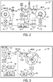
- FIG. 2 is a diagram showing a system 10 for winding and unwinding a product film or web material, i.e., a "web winder system,” with such winding and unwinding being performed in a tightness-controlled manner to ensure integrity of the web material 12.
- the system of FIG. 2 may be, for example, a post-processing apparatus for paper, such as a calendar/presser, printer, or any other processing apparatus for a continuous material web, wherein the material 12 is unwound from one roll and wound onto one or more other rolls during such post-processing.
- FIG. 2 shows an unwinder 14, in which a machine reel or roll 16 of web material 12 is placed, with the web material being unwound from the roll 16 and provided to a machine reel or roll 18 on a winder 20 (i.e., "rewinder") in the system 10.
- each of the unwinder 14 and winder 20 includes a respective drive unit 22, 24 comprised of an electric motor 26, 28 (e.g., AC induction motor) that is controlled by a motor drive 30, 32, such as an adjustable speed drive (ASD.
- the motor drives 30, 32 allow for dynamic control of the motors 26, 28 to control movement of the web material 12 between the unwinder 14 and winder 20.
- a main drive unit 34 is also included in system 10 that is positioned between unwinder 14 and winder 20.
- the main drive unit 34 includes an electric motor 36 (e.g., AC induction motor) that is controlled by a motor drive 38, such as an ASD.
- the main drive unit 34 operates to rotationally drive two nip rolls or rollers 40 that apply a force therebetween to generate a frictional tension along the web material 12 proportional to the force and the coefficient of friction between the material and the nip surface.
- FIG. 2 also shows a control system or device 42 that is operably connected to each of the drive units 22, 24, 34 (i.e., to the motor drives 30, 32, 38) and also to speed and tension sensors 44 positioned at various points along web material 12.
- the control system 42 provides control information to the motor drives 30, 32, 38, which control the respective motors 26, 28, 36 on the basis of the control information to provide a desired web speed and web tightness, for instance.
- the control system 42 may be provided as a PI controller or PID controller, according to embodiments of the invention, that includes a processor 44 therein for executing commands to implement the desired control.
- the control system 42 implements a torque regulated tension control scheme with active damping to control tension in the web material 12.
- the torque regulated tension control with the added active damping provides for a higher crossover frequency of the PI tension controller loop as compared to previously used torque regulated tension control techniques, so as to provide improved/faster tension responses in the system 10 and thereby further improve the dynamic performance of the system.
- K F is the tension constant in kN ⁇ s/m
- ⁇ 1 represents the linear velocity at which the primary volume core axis winds the coiled material
- ⁇ 2 represents the linear velocity at which the transport wheel sends out the coiled material
- ⁇ 1 represents the real-time angular velocity of the primary volume
- R 10 represents the radius of the primary volume core axis
- R 1 represents the real-time radius of the winding
- F 1 represents the tension that applies to the primary volume core axis and the coiled material
- J is the rotational inertia of the winding block
- M 1 is the equivalent drive torque which applies to the winding block
- M F 1 is the mechanical friction torque which applies to the wingding block.
- the control system 42 operates to set the linear velocity of the web process application via controlling of the main drive unit 34 working in a velocity mode, with the main drive unit 34 acting as a master drive in the system 10.
- the winder 20 and its associated secondary drive unit 22 acts as a slave drive operating in the torque closed-loop tension control mode.
- F * is the given tension
- F is the actual tension
- ⁇ m is the actual speed of the winder
- G PI_F ( s ) is the PID of the tension loop
- i sq is the torque producing current
- K ⁇ is the proportionality coefficient between electromagnetic torque and torque current
- K F is the tension coefficient
- K i_F and K z are tension PI coefficients
- T m is the motor torque
- G ⁇ m T is the transfer function between speed and torque
- R is the real-time diameter of the winder
- J is the rotational inertia of the winding block
- T L is the load torque
- G F ⁇ is the dynamic transfer function of tension
- ⁇ n is the natural frequency
- ⁇ is the damping factor
- r is the radius of the main motor
- ⁇ ⁇ is a velocity difference between a speed near the main motor and a speed near the secondary motor.
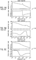
- FIGS. 5A-5C illustrate Bode diagrams 52, 54, 56 for a prior art torque regulated tension control technique ( FIG. 5A ), a prior art speed regulated tension control technique ( FIG. 5B ), and an exemplary torque regulated tension control technique with active damping ( FIG. 5C ).
- the crossover frequency of the proposed tension loop defined in FIG. 5C is larger than those provided in FIGS. 5A and 5B , with a much improved dynamic performance being achieved.
- FIGS. 6A-6C tension step response diagrams 58, 60, 62 are illustrated for a prior art torque regulated tension control technique ( FIG. 6A ), a prior art speed regulated tension control technique ( FIG. 6B ), and an exemplary torque regulated tension control technique with active damping ( FIG. 6C ).
- FIG. 6A the step response of the torque regulated tension control
- FIG. 6C the tension system step response time is significantly faster than those in FIG. 6A and FIG. 6B .
- the main/master drive unit 34 is in the velocity mode and the secondary/slave drive unit 22 is in closed tension loop, applying different tension control methods - i.e., a prior art torque regulated tension control technique, a prior art speed regulated tension control technique, and an exemplary torque regulated tension control technique with active damping.
- tension control method i.e., a prior art torque regulated tension control technique, a prior art speed regulated tension control technique, and an exemplary torque regulated tension control technique with active damping.
- FIGS. 7A-7C The corresponding simulation results are depicted in FIGS. 7A-7C , with tension control step responses 64, 66, 68 being illustrated for the prior art torque regulated tension control technique ( FIG. 7A ), the prior art speed regulated tension control technique ( FIG. 7B ), and the exemplary torque regulated tension control technique with active damping ( FIG. 7C ). It can be seen in FIGS. 7A-7C that the proposed torque mode of closed loop tension control with active damping has the best dynamic performance with superior
- FIGS. 8A-8C illustrate the disturbance rejection capability of each of the different tension control methods, with tension control step responses 70, 72, 74 being illustrated for the prior art torque regulated tension control technique ( FIG. 8A ), the prior art speed regulated tension control technique ( FIG. 8B ), and the exemplary torque regulated tension control technique with active damping ( FIG. 8C ). It can be seen in FIGS. 8A-8C that the proposed torque mode of closed loop tension control with active damping eliminates the tension system oscillation completely when a velocity disturbance is introduced onto the web material.
- embodiments of the invention thus provide a torque regulated tension control with active damping that is accomplished by introducing an additional speed feedback loop to a torque regulated tension control.
- Introduction of the speed feedback loop enables the web winding system to achieve large system natural frequency and damping, thereby increasing system responsiveness in controlling tension in the web material in a dynamic fashion.
- a technical contribution of embodiments of the present invention is that a computer implemented technique is provided for torque regulated tension control with active damping.
- a control system for controlling operation of a main drive unit and a secondary drive unit in a web winder system to provide tension control of a continuous material web as it is translated between an unwinder and winder of the web winder system.
- the control system includes a processor programmed to cause the main drive unit to operate in a velocity mode to set a linear velocity of the continuous material web, receive inputs from tension and speed detectors in the web winder system that detect a tension in and a speed of the continuous material web, and cause the secondary drive unit to operate in a modified torque regulated closed-loop tension control mode so as to control a tension in the web material.
- the processor is further programmed to cause the secondary drive unit to operate according to a torque regulated closed-loop tension control mode, based on inputs from the tension detectors and integrate a speed feedback loop into the torque regulated closed-loop tension control mode, via inputs from the speed detectors, so as to introduce active damping into the tension control.
- the web handling system also includes a secondary drive unit comprising a second electric motor and second adjustable speed drive, the second electric motor and second adjustable speed drive rotationally driving the winder to roll the web material onto the winder.
- the web handling system further includes tension and speed detectors to detect a tension in and a speed of the web material between the unwinder and the winder and a control device to control operation of the main drive unit and the secondary drive unit to rotationally drive the guide rollers and the winder, respectively, at desired rotational speeds, wherein, in controlling operation of the main drive unit and the secondary drive unit to rotationally drive the guide rollers and the winder at desired rotational speeds, the control device is configured to cause the main drive unit to operate in a velocity mode to set a linear velocity of the web material cause the secondary drive unit to operate in a torque regulated closed-loop tension control mode, via inputs from the tension detectors, so as to control a tension in the web material, and integrate a speed feedback loop into the torque regulated closed-loop tension control mode, via inputs from the speed detectors, so as to introduce active damping into the tension control.
- a method of controlling tension control in a continuous material web translated between an unwinder and a winder in a web winder system includes controlling a main drive unit of the web winder system to operate in a velocity mode to set a linear velocity of the continuous material web and controlling a secondary drive unit of the web winder system to operate in a modified torque regulated closed-loop tension control mode so as to control a tension in the web material, wherein, in controlling the secondary drive unit, the modified torque regulated closed-loop tension control mode comprises a torque current loop, a tension loop, and a speed feedback loop to control the tension in the web material.
Landscapes
- Controlling Rewinding, Feeding, Winding, Or Abnormalities Of Webs (AREA)
Abstract
Description
- The present invention relates generally to controlling tension in a continuous material web and, more particularly, to a system and method for controlling tension in a continuous material web in which the system damping is improved and thus better tension responses are achieved.
- The production and processing of strip and sheet materials, i.e., "web handling applications," is actively used in many fields, such as web printing, newspaper pressing, and so on. In such web handling applications, it is a basic requirement that a web of material is produced to a specification which typically includes at least a predetermined thickness and predetermined material properties. To achieve such predetermined requirements, any mechanical forces applied to the web during processing must be accurately controlled. A transfer roll that conveys strip material from one part of a process to another must convey the web material while exerting a controlled tension or pressure that is accurately controlled and evenly distributed over the width of the roll.
- In controlling mechanical forces applied to the web, the most important requirement is to make the tension and the linear velocity of the system stable. Thus, quite a few tension control methods have been proposed, such as conventional Proportional-Integral (PI) control, fuzzy self-adaptive Proportional-Integral-Derivative (PID) control, and active disturbance rejection control, for example. Conventional PI control methods are mainly based on torque regulated or speed regulated control.
FIGS. 1A and 1B illustrate such torque regulated (1A) and speed regulated (1B) tension controls, respectively. As it can be seen, the toque regulated tension control technique consists of a torque current loop and a tension loop, while the speed regulated tension control technique not only has a torque current loop and a tension control loop, but also has an intermediate speed loop cascaded into the tension loop. FromFIG. 1A , the second order open loop transfer function of the torque regulated tension control is obtained according to:
FIG. 1A and [Eqn. 1], F* is the given tension, F is the actual tension,
m T is the transfer function between speed and torque, R is the real-time diameter of the winder, TL is the load torque, GFΔν is the dynamic transfer function of tension, ωn is the natural frequency, J is the rotational inertia of the winding block, r is the radius of the main motor, and Δν is a velocity difference between a speed near the main motor and a speed near the secondary motor. - From
FIG. 1B , the speed regulated tension control is a third order system and is obtained according to:
FIG. 1B and [Eqn. 2], F* is the given tension, F is the actual tension,

m T is the transfer function between speed and torque, J is the rotational inertia of the winding block, R is the real-time diameter of the winder, TL is the load torque, GFΔν is the dynamic transfer function of tension, Gd is the delay of speed sampling, r is the radius of the main motor, and Δν is a velocity difference between a speed near the main motor and a speed near the secondary motor. - In order to have a good dynamic performance for tension control, Kp and Ki, of tension PI controller gains should be properly designed to achieve sufficient system gain and phase margins. However, it is recognized that the crossover frequency of torque regulated tension control is smaller than that of speed regulated tension control. The step response of torque regulated tension control tends to vibrate more easily because the crossover frequency of the torque regulated tension control system is limited by low damping of its natural resonant frequency. Although a derivation term can be added in PID control to achieve fast system tension response, it will introduce noise to the system. This small incurred noise may be acceptable in common continuous system; however, it is improper for systems with high control performance requirements, such as discontinuous systems. In the speed regulated tension control, the dynamic performance is improved by introducing the cascaded speed loop. However, the crossover frequency of this kind of tension loop is limited by the relatively low speed loop bandwidth, especially for systems with a large inertia.
- It would therefore be desirable to provide a system and method for controlling tension in a continuous material web, with such a system and method providing a fast, dynamic system tension response with low vibration and low noise and useable with a variety of different systems, including systems with a large inertia.
- In accordance with one aspect of the invention, a control system for controlling operation of a main drive unit and a secondary drive unit in a web winder system to provide tension control of a continuous material web as it is translated between an unwinder and winder of the web winder system is provided. The control system includes a processor programmed to cause the main drive unit to operate in a velocity mode to set a linear velocity of the continuous material web, receive inputs from tension and speed detectors in the web winder system that detect a tension in and a speed of the continuous material web, and cause the secondary drive unit to operate in a modified torque regulated closed-loop tension control mode so as to control a tension in the web material. In operating in the modified torque regulated closed-loop tension control mode, the processor is further programmed to cause the secondary drive unit to operate according to a torque regulated closed-loop tension control mode, based on inputs from the tension detectors and integrate a speed feedback loop into the torque regulated closed-loop tension control mode, via inputs from the speed detectors, so as to introduce active damping into the tension control.
- In accordance with another aspect of the invention, a web handling system for controlling tension in a web material includes a winder and unwinder between which a web material is transferred and a main drive unit comprising a first electric motor and first adjustable speed drive, the first electric motor and first adjustable speed drive rotationally driving guide rollers to translate the web material from the unwinder to the winder. The web handling system also includes a secondary drive unit comprising a second electric motor and second adjustable speed drive, the second electric motor and second adjustable speed drive rotationally driving the winder to roll the web material onto the winder. The web handling system further includes tension and speed detectors to detect a tension in and a speed of the web material between the unwinder and the winder and a control device to control operation of the main drive unit and the secondary drive unit to rotationally drive the guide rollers and the winder, respectively, at desired rotational speeds, wherein, in controlling operation of the main drive unit and the secondary drive unit to rotationally drive the guide rollers and the winder at desired rotational speeds, the control device is configured to cause the main drive unit to operate in a velocity mode to set a linear velocity of the web material cause the secondary drive unit to operate in a torque regulated closed-loop tension control mode, via inputs from the tension detectors, so as to control a tension in the web material, and integrate a speed feedback loop into the torque regulated closed-loop tension control mode, via inputs from the speed detectors, so as to introduce active damping into the tension control.
- In accordance with yet another aspect of the invention, a method of controlling tension control in a continuous material web translated between an unwinder and a winder in a web winder system includes controlling a main drive unit of the web winder system to operate in a velocity mode to set a linear velocity of the continuous material web and controlling a secondary drive unit of the web winder system to operate in a modified torque regulated closed-loop tension control mode so as to control a tension in the web material, wherein, in controlling the secondary drive unit, the modified torque regulated closed-loop tension control mode comprises a torque current loop, a tension loop, and a speed feedback loop to control the tension in the web material.
- Various other features and advantages of the present invention will be made apparent from the following detailed description and the drawings.
- The drawings illustrate preferred embodiments presently contemplated for carrying out the invention.
- In the drawings:
-
FIG. 1A is a block diagram of a torque regulated tension control scheme for controlling tension in a continuous material web, as known in the prior art. -
FIG. 1B is a block diagram of a speed regulated tension control scheme for controlling tension in a continuous material web, as known in the prior art -
FIG. 2 is a block schematic diagram of a web winder system useable with embodiments of the invention. -
FIG. 3 is a simplified block schematic diagram of the web winder system ofFIG. 2 . -
FIG. 4 is a block diagram of a torque regulated tension control scheme with active damping for controlling tension in a continuous material web, according to an embodiment of the invention. -
FIGS. 5A-5C are graphs illustrating Bode diagrams for a prior art torque regulated tension control technique, a prior art speed regulated tension control technique, and an exemplary torque regulated tension control technique with active damping, respectively. -
FIGS. 6A-6C are graphs illustrating tension step response diagrams for a prior art torque regulated tension control technique, a prior art speed regulated tension control technique, and an exemplary torque regulated tension control technique with active damping, respectively. -
FIGS. 7A-7C are graphs illustrating tension control step responses resulting from an exemplary simulation, for a prior art torque regulated tension control technique, a prior art speed regulated tension control technique, and an exemplary torque regulated tension control technique with active damping, respectively. -
FIGS. 8A-8C are graphs illustrating tension control step responses resulting from an exemplary simulation where velocity disturbance is introduced, for a prior art torque regulated tension control technique, a prior art speed regulated tension control technique, and an exemplary torque regulated tension control technique with active damping, respectively. - Embodiments of the invention relate to a system and method for controlling tension in a continuous material web and, more particularly, to a system and method for controlling tension in a continuous material web in which the system damping is improved and thus better tension responses are achieved. Main and secondary drive units in the web winding system are operated in a velocity mode and a modified torque regulated closed-loop tension control mode, respectively, with a speed feedback loop being integrated into the torque regulated closed-loop tension control mode to improve system damping and achieve faster response time in controlling the tension in the continuous material web.
-
FIG. 2 is a diagram showing asystem 10 for winding and unwinding a product film or web material, i.e., a "web winder system," with such winding and unwinding being performed in a tightness-controlled manner to ensure integrity of theweb material 12. The system ofFIG. 2 may be, for example, a post-processing apparatus for paper, such as a calendar/presser, printer, or any other processing apparatus for a continuous material web, wherein thematerial 12 is unwound from one roll and wound onto one or more other rolls during such post-processing. -
FIG. 2 shows anunwinder 14, in which a machine reel orroll 16 ofweb material 12 is placed, with the web material being unwound from theroll 16 and provided to a machine reel orroll 18 on a winder 20 (i.e., "rewinder") in thesystem 10. According to the embodiment ofFIG. 2 , each of theunwinder 14 andwinder 20 includes arespective drive unit electric motor 26, 28 (e.g., AC induction motor) that is controlled by amotor drive motors web material 12 between theunwinder 14 andwinder 20. - As further shown in
FIG. 2 , amain drive unit 34 is also included insystem 10 that is positioned betweenunwinder 14 andwinder 20. Themain drive unit 34 includes an electric motor 36 (e.g., AC induction motor) that is controlled by amotor drive 38, such as an ASD. Themain drive unit 34 operates to rotationally drive two nip rolls orrollers 40 that apply a force therebetween to generate a frictional tension along theweb material 12 proportional to the force and the coefficient of friction between the material and the nip surface. -
FIG. 2 also shows a control system ordevice 42 that is operably connected to each of thedrive units tension sensors 44 positioned at various points alongweb material 12. Thecontrol system 42 provides control information to the motor drives 30, 32, 38, which control therespective motors control system 42 may be provided as a PI controller or PID controller, according to embodiments of the invention, that includes aprocessor 44 therein for executing commands to implement the desired control. - According to an exemplary embodiment, the
control system 42 implements a torque regulated tension control scheme with active damping to control tension in theweb material 12. The torque regulated tension control with the added active damping provides for a higher crossover frequency of the PI tension controller loop as compared to previously used torque regulated tension control techniques, so as to provide improved/faster tension responses in thesystem 10 and thereby further improve the dynamic performance of the system. Following here below, and with reference to a simplified diagram of theweb winder system 10 and associated measurable parameters of thesystem 10 provided inFIG. 3 , is a discussion of the control scheme implemented bycontrol system 42 for controlling operation of themain drive unit 34 and the drive unit 22 (i.e., the "secondary drive unit"). InFIG. 3 , KF is the tension constant in kN·s/m, ν 1 represents the linear velocity at which the primary volume core axis winds the coiled material, ν 2 represents the linear velocity at which the transport wheel sends out the coiled material, ω 1 represents the real-time angular velocity of the primary volume, R 10 represents the radius of the primary volume core axis, R 1 represents the real-time radius of the winding, F 1 represents the tension that applies to the primary volume core axis and the coiled material, J is the rotational inertia of the winding block, M 1 is the equivalent drive torque which applies to the winding block, and M F1 is the mechanical friction torque which applies to the wingding block. - In operation of the
system 10 and the movement ofweb material 12 thereby, thecontrol system 42 operates to set the linear velocity of the web process application via controlling of themain drive unit 34 working in a velocity mode, with themain drive unit 34 acting as a master drive in thesystem 10. Thewinder 20 and its associatedsecondary drive unit 22 acts as a slave drive operating in the torque closed-loop tension control mode. Assuming that no viscous term and no slip between theroll 18 andweb material 12, the tension model is expressed as:
- As can be seen in the block diagram of
FIG. 4 , in implementing the torque regulated tension control scheme with active damping 48 (i.e., the "modified torque regulated closed-loop tension control mode") viacontrol system 42, the numerator includes a first order term of 's', which means that the system damping could be increased by speed feedback, indicated at 50, with the transfer function between torque current and motor speed being expressed as:
- Accordingly, the open loop transfer function therefore becomes:

FIG. 4 and [Eqn. 4] and [Eqn. 5], F* is the given tension, F is the actual tension, ωm is the actual speed of the winder, GPI_F (s) is the PID of the tension loop, isq is the torque producing current, Kα is the proportionality coefficient between electromagnetic torque and torque current, KF is the tension coefficient, Ki_F and Kz are tension PI coefficients, Tm is the motor torque, Gωm T is the transfer function between speed and torque, R is the real-time diameter of the winder, J is the rotational inertia of the winding block, TL is the load torque, GFΔν is the dynamic transfer function of tension, ωn is the natural frequency, ξ is the damping factor, r is the radius of the main motor, and Δν is a velocity difference between a speed near the main motor and a speed near the secondary motor. - As can be seen in comparing the open loop transfer function of [Eqn. 5] implemented in the modified torque regulated tension control scheme (i.e., with active damping) to the open loop transfer function of [Eqn. 1] implemented in a prior art torque regulated tension control scheme, the system damping is increased significantly and the dominant pole pair {wp , ξ p } in the plant of tension control is moved into the location:

- With proper feedback parameter Kz and tuned Kp, Ki of tension PI control parameters, a crossover frequency of the proposed tension loop is increased and an improved dynamic performance is achieved as compared prior art torque regulated and speed regulated tension control techniques.
FIGS. 5A-5C illustrate Bode diagrams 52, 54, 56 for a prior art torque regulated tension control technique (FIG. 5A ), a prior art speed regulated tension control technique (FIG. 5B ), and an exemplary torque regulated tension control technique with active damping (FIG. 5C ). As can be seen by a comparison of the figures, the crossover frequency of the proposed tension loop defined inFIG. 5C is larger than those provided inFIGS. 5A and 5B , with a much improved dynamic performance being achieved. - Referring now to
FIGS. 6A-6C , tension step response diagrams 58, 60, 62 are illustrated for a prior art torque regulated tension control technique (FIG. 6A ), a prior art speed regulated tension control technique (FIG. 6B ), and an exemplary torque regulated tension control technique with active damping (FIG. 6C ). As can be seen by a comparison of the figures, the step response of the torque regulated tension control (FIG. 6A ) tends to vibrate more easily based on the crossover frequency of the torque regulated tension control system being limited by low damping of its natural resonant frequency, with such vibration being eliminated in the tension step response defined inFIG. 6C . As shown inFIG. 6C , the tension system step response time is significantly faster than those inFIG. 6A and FIG. 6B . - An example of tension control results achieved via implementation of an exemplary torque regulated tension control technique with active damping is set forth here below, according to an exemplary embodiment. In the example, a time-domain simulation platform utilizing Matlab/Simulink evaluates the performance of the proposed tension control method, with the main system parameters including:
- Asynchronous machine: 30kW, 50Hz, 380V
- DC-bus voltage: 540V
- Switching frequency: 6kHz
- Sampling frequency: 12kHz
- Initial radius of winder: 0.1m
- Radius of main driver: 0.02m
- Feedback slip without tension (S): 0.08
- Roll thickness (σ): 10um
- Coefficient of forward slip effect (β): 0.5kN
- Cross-sectional area of winder (A0): 2.27mm2
- Distance between winder and main drive (L): 3500mm
- Elasticity modulus (E): 2.058×10⁵N/mm2
- Linear velocity of processing (Vb): 3m/s
- In the simulation, the main/
master drive unit 34 is in the velocity mode and the secondary/slave drive unit 22 is in closed tension loop, applying different tension control methods - i.e., a prior art torque regulated tension control technique, a prior art speed regulated tension control technique, and an exemplary torque regulated tension control technique with active damping. The corresponding simulation results are depicted inFIGS. 7A-7C , with tensioncontrol step responses FIG. 7A ), the prior art speed regulated tension control technique (FIG. 7B ), and the exemplary torque regulated tension control technique with active damping (FIG. 7C ). It can be seen inFIGS. 7A-7C that the proposed torque mode of closed loop tension control with active damping has the best dynamic performance with superior step response time, while not exhibiting any overshoot. - Referring now to
FIGS. 8A-8C , the disturbance rejection capability of each of the different tension control methods is evaluated.FIGS. 8A-8C illustrate the performance of the tension loop when a velocity disturbance is introduced, with tensioncontrol step responses FIG. 8A ), the prior art speed regulated tension control technique (FIG. 8B ), and the exemplary torque regulated tension control technique with active damping (FIG. 8C ). It can be seen inFIGS. 8A-8C that the proposed torque mode of closed loop tension control with active damping eliminates the tension system oscillation completely when a velocity disturbance is introduced onto the web material. - Beneficially, embodiments of the invention thus provide a torque regulated tension control with active damping that is accomplished by introducing an additional speed feedback loop to a torque regulated tension control. Introduction of the speed feedback loop enables the web winding system to achieve large system natural frequency and damping, thereby increasing system responsiveness in controlling tension in the web material in a dynamic fashion.
- A technical contribution of embodiments of the present invention is that a computer implemented technique is provided for torque regulated tension control with active damping.
- According to one embodiment of the present invention, a control system for controlling operation of a main drive unit and a secondary drive unit in a web winder system to provide tension control of a continuous material web as it is translated between an unwinder and winder of the web winder system is provided. The control system includes a processor programmed to cause the main drive unit to operate in a velocity mode to set a linear velocity of the continuous material web, receive inputs from tension and speed detectors in the web winder system that detect a tension in and a speed of the continuous material web, and cause the secondary drive unit to operate in a modified torque regulated closed-loop tension control mode so as to control a tension in the web material. In operating in the modified torque regulated closed-loop tension control mode, the processor is further programmed to cause the secondary drive unit to operate according to a torque regulated closed-loop tension control mode, based on inputs from the tension detectors and integrate a speed feedback loop into the torque regulated closed-loop tension control mode, via inputs from the speed detectors, so as to introduce active damping into the tension control.
- According to another embodiment of the present invention, web handling system for controlling tension in a web material includes a winder and unwinder between which a web material is transferred and a main drive unit comprising a first electric motor and first adjustable speed drive, the first electric motor and first adjustable speed drive rotationally driving guide rollers to translate the web material from the unwinder to the winder. The web handling system also includes a secondary drive unit comprising a second electric motor and second adjustable speed drive, the second electric motor and second adjustable speed drive rotationally driving the winder to roll the web material onto the winder. The web handling system further includes tension and speed detectors to detect a tension in and a speed of the web material between the unwinder and the winder and a control device to control operation of the main drive unit and the secondary drive unit to rotationally drive the guide rollers and the winder, respectively, at desired rotational speeds, wherein, in controlling operation of the main drive unit and the secondary drive unit to rotationally drive the guide rollers and the winder at desired rotational speeds, the control device is configured to cause the main drive unit to operate in a velocity mode to set a linear velocity of the web material cause the secondary drive unit to operate in a torque regulated closed-loop tension control mode, via inputs from the tension detectors, so as to control a tension in the web material, and integrate a speed feedback loop into the torque regulated closed-loop tension control mode, via inputs from the speed detectors, so as to introduce active damping into the tension control.
- According to yet another embodiment of the present invention, a method of controlling tension control in a continuous material web translated between an unwinder and a winder in a web winder system includes controlling a main drive unit of the web winder system to operate in a velocity mode to set a linear velocity of the continuous material web and controlling a secondary drive unit of the web winder system to operate in a modified torque regulated closed-loop tension control mode so as to control a tension in the web material, wherein, in controlling the secondary drive unit, the modified torque regulated closed-loop tension control mode comprises a torque current loop, a tension loop, and a speed feedback loop to control the tension in the web material.
- The present invention has been described in terms of the preferred embodiment, and it is recognized that equivalents, alternatives, and modifications, aside from those expressly stated, are possible and within the scope of the appending claims.
Claims (14)
- A control system (42) for controlling operation of a main drive unit (34) and a secondary drive unit (22) in a web winder system (10) to provide tension control of a continuous material web (12) as it is translated between an unwinder (14) and winder (20) of the web winder system (10), the control system (42) having a processor (44) programmed to:cause the main drive unit (34) to operate in a velocity mode to set a linear velocity of the continuous material web (12);receive inputs from tension and speed detectors (44) in the web winder system (10) that detect a tension in and a speed of the continuous material web (12); andcause the secondary drive unit (22) to operate in a modified torque regulated closed-loop tension control mode so as to control a tension in the continuous material web (12), wherein operating in the modified torque regulated closed-loop tension control mode comprises:causing the secondary drive unit (22) to operate according to a torque regulated closed-loop tension control mode, based on inputs from the tension detectors (44); andintegrating a speed feedback loop into the torque regulated closed-loop tension control mode, via inputs from the speed detectors (44), so as to introduce active damping into the tension control.
- The control system (42) of claim 1 wherein the processor (44) is programmed to cause the secondary drive unit (22) to operate in a modified torque regulated closed-loop tension control mode according to a closed loop transfer function defined as:

m T is the transfer function between speed and torque, GFΔν is the dynamic transfer function of tension, R is the real-time diameter of the winder (20), J is the rotational inertia of the winding block, s is a first order speed term. - The control system (42) of claim 1 wherein the processor (44) is programmed to cause the secondary drive unit (22) to operate in a modified torque regulated closed-loop tension control mode according to an open loop transfer function defined as:

- The control system (42) of claim 3 wherein a dominant pole pair in the open loop transfer function has a location defined by:

- The control system (42) of claim 1 wherein the processor (44) is programmed to increase a crossover frequency of the torque regulated closed-loop tension control mode based on the integration of the speed feedback loop.
- The control system (42) of claim 1 wherein the processor (44) is programmed to eliminate tension oscillation during a velocity disturbance of the continuous material web (12), based on the integration of the speed feedback loop into the torque regulated closed-loop tension control mode.
- The control system (42) of claim 1 wherein the processor (44) is programmed to cause the main drive unit (34) to operate as a master drive unit and the secondary drive unit (22) to operate as a slave drive unit.
- The control system (42) of claim 1 wherein the control system (42) is implemented in a web winder system (10) that comprises:a winder (20) and unwinder (14) between which a continuous material web (12) is transferred;a main drive unit (34) comprising a first electric motor (36) and first adjustable speed drive (38), the first electric motor (36) and first adjustable speed drive (38) rotationally driving guide rollers (40) to translate the continuous material web (12) from the unwinder (14) to the winder (20);a secondary drive unit (22) comprising a second electric motor (26) and second adjustable speed drive (30), the second electric motor (26) and second adjustable speed drive (30) rotationally driving the winder (20) to roll the continuous material web (12) onto the winder (20); andtension and speed detectors (44) to detect a tension in and a speed of the continuous material web (12) between the unwinder (14) and the winder (20).
- The control system (42) of claim 8 wherein the web winder system (10) further comprises an additional drive unit including a third electric motor (28) and third adjustable speed drive (32), the third electric motor (28) and third adjustable speed drive (32) rotationally driving the unwinder (14) to unroll the web material (12).
- The control system (42) of claim 1 wherein the processor (44) is integrated into a Proportional-Integral (PI) controller.
- A method of controlling tension control in a continuous material web (12) translated between an unwinder (14) and a winder (20) in a web winder system (10), the method comprising:controlling a main drive unit (34) of the web winder system (10) to operate in a velocity mode to set a linear velocity of the continuous material web (12); andcontrolling a secondary drive unit (22) of the web winder system (10) to operate in a modified torque regulated closed-loop tension control mode so as to control a tension in the web material (12);wherein, in controlling the secondary drive unit (22), the modified torque regulated closed-loop tension control mode comprises a torque current loop, a tension loop, and a speed feedback loop to control the tension in the web material (12).
- The method of claim 11 wherein controlling the secondary drive unit (22) of the web winder system (10) to operate in the modified torque regulated closed-loop tension control mode further comprises:receiving inputs from tension and speed detectors (44) in the web winder system (10) that detect a tension in and a speed of the continuous material web (12);causing the secondary drive unit (22) to operate in a torque regulated closed-loop tension control mode comprising the torque current loop and the tension loop, via inputs from the tension detectors (44), so as to control a tension in the web material (12); andintegrating the speed feedback loop into the torque regulated closed-loop tension control mode, via inputs from the speed detectors (44), so as to introduce active damping into the tension control.
- The method of claim 11 wherein the modified torque regulated closed-loop tension control mode is defined as a closed loop transfer function according to:

m T is the transfer function between speed and torque, GFΔν is the dynamic transfer function of tension, R is the real-time diameter of the winder (20), J is the rotational inertia of the winding block, s is a first order speed term. - The method of claim 11 wherein the modified torque regulated closed-loop tension control mode is defined as an open loop transfer function according to:

Applications Claiming Priority (1)
| Application Number | Priority Date | Filing Date | Title |
|---|---|---|---|
| US15/435,549 US10377598B2 (en) | 2017-02-17 | 2017-02-17 | Dynamic performance and active damping methods in web winder tension control systems |
Publications (2)
| Publication Number | Publication Date |
|---|---|
| EP3363755A1 true EP3363755A1 (en) | 2018-08-22 |
| EP3363755B1 EP3363755B1 (en) | 2020-06-03 |
Family
ID=61198705
Family Applications (1)
| Application Number | Title | Priority Date | Filing Date |
|---|---|---|---|
| EP18156194.5A Active EP3363755B1 (en) | 2017-02-17 | 2018-02-09 | Dynamic performance and active damping methods in web winder tension control systems |
Country Status (2)
| Country | Link |
|---|---|
| US (1) | US10377598B2 (en) |
| EP (1) | EP3363755B1 (en) |
Cited By (1)
| Publication number | Priority date | Publication date | Assignee | Title |
|---|---|---|---|---|
| CN116902657A (en) * | 2023-09-13 | 2023-10-20 | 深圳市阿尔斯自动化科技有限公司 | Electrical control system and control method of die-cutting slitting machine |
Families Citing this family (7)
| Publication number | Priority date | Publication date | Assignee | Title |
|---|---|---|---|---|
| US11834289B2 (en) * | 2018-08-02 | 2023-12-05 | Totani Corporation | Intermittent feed device |
| CN109739292A (en) * | 2019-01-23 | 2019-05-10 | 济南大学 | Photovoltaic system MPPT fuzzy active disturbance rejection control method, controller and system |
| CN113183440B (en) * | 2021-04-28 | 2023-01-24 | 重庆科技学院 | Butyl rubber vibration damping belt production line and tension control method |
| CN116534644A (en) * | 2023-04-23 | 2023-08-04 | 山西太钢不锈钢精密带钢有限公司 | Coil tension control method for ultra-thin stainless precision strip steel based on fuzzy PID |
| CN116618448B (en) * | 2023-06-27 | 2026-02-06 | 鞍钢集团北京研究院有限公司 | Single-frame reversible rolling mill coiling tension self-adaptive control method and system |
| TWI876721B (en) * | 2023-11-30 | 2025-03-11 | 財團法人金屬工業研究發展中心 | A cascade control winding system |
| CN120841281B (en) * | 2025-09-22 | 2026-01-06 | 福州印团网印刷有限公司 | Method and system for dynamic balance control of paper tension in high-speed paper feeding mechanism |
Citations (4)
| Publication number | Priority date | Publication date | Assignee | Title |
|---|---|---|---|---|
| JPH07251216A (en) * | 1994-03-14 | 1995-10-03 | Mitsubishi Electric Corp | Looper tension controller |
| US6047275A (en) * | 1997-10-14 | 2000-04-04 | Allen-Bradley Company, Llc | Fuzzy logic winder analyzer |
| JP2009240033A (en) * | 2008-03-26 | 2009-10-15 | Jfe Steel Corp | Looper equipment |
| KR20140119851A (en) * | 2013-03-27 | 2014-10-13 | (주)프로템 | Servo motor multi control device |
Family Cites Families (13)
| Publication number | Priority date | Publication date | Assignee | Title |
|---|---|---|---|---|
| US3829745A (en) * | 1973-02-02 | 1974-08-13 | Xerox Corp | Techniques for maintaining substantially constant tension in web |
| US4151594A (en) * | 1976-02-26 | 1979-04-24 | Bobst-Champlain, Inc. | Web tension control for high-speed web handling equipment |
| US4448366A (en) * | 1982-07-08 | 1984-05-15 | Westinghouse Electric Corp. | Coil diameter tracking system and tension regulation system using such tracking system |
| EP0745890A1 (en) * | 1995-05-30 | 1996-12-04 | Eastman Kodak Company | Film web motion control system |
| US6314333B1 (en) * | 1998-07-03 | 2001-11-06 | Kimberly-Clark Worldwide, Inc. | Method and apparatus for controlling web tension by actively controlling velocity and acceleration of a dancer roll |
| DE19923204B4 (en) * | 1999-05-20 | 2004-04-29 | Man Roland Druckmaschinen Ag | Speed control arrangement for an unwinder |
| US6845282B2 (en) * | 2002-09-04 | 2005-01-18 | The Procter & Gamble Company | Method of controlling tension in a web |
| DE102004006232B3 (en) * | 2004-02-09 | 2005-07-21 | Koenig & Bauer Ag | Drawing-in process for a web in printing press has second motor controlled on basis of preset torque |
| US7092781B2 (en) * | 2004-12-10 | 2006-08-15 | The Procter & Gamble Company | Method of controlling tension in a web |
| CN106458494B (en) * | 2014-05-23 | 2017-11-24 | 三菱电机株式会社 | Conveying control device between roller |
| US10315876B2 (en) * | 2014-11-27 | 2019-06-11 | Mitsubishi Electric Corporation | Roller-to-roller conveyance control apparatus |
| US9925807B2 (en) * | 2015-09-30 | 2018-03-27 | Brother Kogyo Kabushiki Kaisha | Conveyance system, sheet processing system, and controller |
| JP6913488B2 (en) * | 2017-03-21 | 2021-08-04 | 株式会社Screenホールディングス | Transport control method, transport device and printing device |
-
2017
- 2017-02-17 US US15/435,549 patent/US10377598B2/en active Active
-
2018
- 2018-02-09 EP EP18156194.5A patent/EP3363755B1/en active Active
Patent Citations (4)
| Publication number | Priority date | Publication date | Assignee | Title |
|---|---|---|---|---|
| JPH07251216A (en) * | 1994-03-14 | 1995-10-03 | Mitsubishi Electric Corp | Looper tension controller |
| US6047275A (en) * | 1997-10-14 | 2000-04-04 | Allen-Bradley Company, Llc | Fuzzy logic winder analyzer |
| JP2009240033A (en) * | 2008-03-26 | 2009-10-15 | Jfe Steel Corp | Looper equipment |
| KR20140119851A (en) * | 2013-03-27 | 2014-10-13 | (주)프로템 | Servo motor multi control device |
Cited By (2)
| Publication number | Priority date | Publication date | Assignee | Title |
|---|---|---|---|---|
| CN116902657A (en) * | 2023-09-13 | 2023-10-20 | 深圳市阿尔斯自动化科技有限公司 | Electrical control system and control method of die-cutting slitting machine |
| CN116902657B (en) * | 2023-09-13 | 2023-11-21 | 深圳市阿尔斯自动化科技有限公司 | Electrical control system and control method of die-cutting slitting machine |
Also Published As
| Publication number | Publication date |
|---|---|
| EP3363755B1 (en) | 2020-06-03 |
| US20180237249A1 (en) | 2018-08-23 |
| US10377598B2 (en) | 2019-08-13 |
Similar Documents
| Publication | Publication Date | Title |
|---|---|---|
| EP3363755B1 (en) | Dynamic performance and active damping methods in web winder tension control systems | |
| US4704171A (en) | Laminating device with paper tension control | |
| EP3988485B1 (en) | Parameterization of a traction controller | |
| CN116281334B (en) | Coil tension control system and control method | |
| JP2005506257A (en) | Web tension control and web retention by active control of festoon speed and bias. | |
| JPS58183554A (en) | Method of controlling hoisting of material | |
| US20110246127A1 (en) | Method for Determining at Least One Controller Parameter of a Dancer Position Control Element | |
| WO2013168026A1 (en) | Controller and system for controllably rotating a roll of material | |
| CA2276472A1 (en) | Method and apparatus for controlling web tension by actively controlling velocity and acceleration of a dancer roll | |
| CN110502043B (en) | Dynamic performance and active damping methods in web winder tension control systems | |
| US6828743B2 (en) | Method and device for controlling a winder | |
| EP3378808B1 (en) | A method of controlling operation of a winder for a fiber web | |
| JP2604334B2 (en) | Web processing machine | |
| JPH0151422B2 (en) | ||
| JP2988932B1 (en) | Winder with tension control | |
| Dwivedula et al. | Effect of backlash on web tension in roll-to-roll manufacturing systems: Mathematical model, mitigation method and experimental evaluation | |
| Allaoua et al. | Multi-drive paper system control based on multi-input multi-output PID controller | |
| JP2000103556A (en) | Sheet rewinding tension control method | |
| JP2874736B2 (en) | Tie winding tension control device for slitter for sheet material | |
| JPH07257797A (en) | Winding tension control method for band-shaped material and band-shaped material winding device using the same | |
| JPS60262766A (en) | Taking-up driving apparatus of slitter | |
| Kępski et al. | Tension Control: Open-Loop Torque Control in Material Unwinding Process | |
| JPH04280766A (en) | Winding tension control device for sheet-shaped object winder | |
| JPH06305617A (en) | Tension control method | |
| JPH05116823A (en) | Tension control device for sheet-like material |
Legal Events
| Date | Code | Title | Description |
|---|---|---|---|
| PUAI | Public reference made under article 153(3) epc to a published international application that has entered the european phase |
Free format text: ORIGINAL CODE: 0009012 |
|
| STAA | Information on the status of an ep patent application or granted ep patent |
Free format text: STATUS: REQUEST FOR EXAMINATION WAS MADE |
|
| 17P | Request for examination filed |
Effective date: 20180209 |
|
| AK | Designated contracting states |
Kind code of ref document: A1 Designated state(s): AL AT BE BG CH CY CZ DE DK EE ES FI FR GB GR HR HU IE IS IT LI LT LU LV MC MK MT NL NO PL PT RO RS SE SI SK SM TR |
|
| AX | Request for extension of the european patent |
Extension state: BA ME |
|
| RIN1 | Information on inventor provided before grant (corrected) |
Inventor name: YAO, WENXI Inventor name: LU, ZHENGYU Inventor name: CHEN, FAYI Inventor name: LI, HUAQIANG |
|
| RIC1 | Information provided on ipc code assigned before grant |
Ipc: B65H 23/18 20060101ALI20191212BHEP Ipc: B65H 23/195 20060101ALI20191212BHEP Ipc: B65H 23/10 20060101ALI20191212BHEP Ipc: B65H 23/04 20060101ALI20191212BHEP Ipc: B65H 23/06 20060101AFI20191212BHEP |
|
| GRAP | Despatch of communication of intention to grant a patent |
Free format text: ORIGINAL CODE: EPIDOSNIGR1 |
|
| STAA | Information on the status of an ep patent application or granted ep patent |
Free format text: STATUS: GRANT OF PATENT IS INTENDED |
|
| INTG | Intention to grant announced |
Effective date: 20200210 |
|
| GRAS | Grant fee paid |
Free format text: ORIGINAL CODE: EPIDOSNIGR3 |
|
| GRAA | (expected) grant |
Free format text: ORIGINAL CODE: 0009210 |
|
| STAA | Information on the status of an ep patent application or granted ep patent |
Free format text: STATUS: THE PATENT HAS BEEN GRANTED |
|
| AK | Designated contracting states |
Kind code of ref document: B1 Designated state(s): AL AT BE BG CH CY CZ DE DK EE ES FI FR GB GR HR HU IE IS IT LI LT LU LV MC MK MT NL NO PL PT RO RS SE SI SK SM TR |
|
| REG | Reference to a national code |
Ref country code: GB Ref legal event code: FG4D |
|
| REG | Reference to a national code |
Ref country code: AT Ref legal event code: REF Ref document number: 1276806 Country of ref document: AT Kind code of ref document: T Effective date: 20200615 Ref country code: CH Ref legal event code: EP |
|
| REG | Reference to a national code |
Ref country code: DE Ref legal event code: R096 Ref document number: 602018004958 Country of ref document: DE |
|
| REG | Reference to a national code |
Ref country code: LT Ref legal event code: MG4D |
|
| PG25 | Lapsed in a contracting state [announced via postgrant information from national office to epo] |
Ref country code: LT Free format text: LAPSE BECAUSE OF FAILURE TO SUBMIT A TRANSLATION OF THE DESCRIPTION OR TO PAY THE FEE WITHIN THE PRESCRIBED TIME-LIMIT Effective date: 20200603 Ref country code: GR Free format text: LAPSE BECAUSE OF FAILURE TO SUBMIT A TRANSLATION OF THE DESCRIPTION OR TO PAY THE FEE WITHIN THE PRESCRIBED TIME-LIMIT Effective date: 20200904 Ref country code: SE Free format text: LAPSE BECAUSE OF FAILURE TO SUBMIT A TRANSLATION OF THE DESCRIPTION OR TO PAY THE FEE WITHIN THE PRESCRIBED TIME-LIMIT Effective date: 20200603 Ref country code: NO Free format text: LAPSE BECAUSE OF FAILURE TO SUBMIT A TRANSLATION OF THE DESCRIPTION OR TO PAY THE FEE WITHIN THE PRESCRIBED TIME-LIMIT Effective date: 20200903 Ref country code: FI Free format text: LAPSE BECAUSE OF FAILURE TO SUBMIT A TRANSLATION OF THE DESCRIPTION OR TO PAY THE FEE WITHIN THE PRESCRIBED TIME-LIMIT Effective date: 20200603 |
|
| REG | Reference to a national code |
Ref country code: NL Ref legal event code: MP Effective date: 20200603 |
|
| PG25 | Lapsed in a contracting state [announced via postgrant information from national office to epo] |
Ref country code: RS Free format text: LAPSE BECAUSE OF FAILURE TO SUBMIT A TRANSLATION OF THE DESCRIPTION OR TO PAY THE FEE WITHIN THE PRESCRIBED TIME-LIMIT Effective date: 20200603 Ref country code: LV Free format text: LAPSE BECAUSE OF FAILURE TO SUBMIT A TRANSLATION OF THE DESCRIPTION OR TO PAY THE FEE WITHIN THE PRESCRIBED TIME-LIMIT Effective date: 20200603 Ref country code: HR Free format text: LAPSE BECAUSE OF FAILURE TO SUBMIT A TRANSLATION OF THE DESCRIPTION OR TO PAY THE FEE WITHIN THE PRESCRIBED TIME-LIMIT Effective date: 20200603 Ref country code: BG Free format text: LAPSE BECAUSE OF FAILURE TO SUBMIT A TRANSLATION OF THE DESCRIPTION OR TO PAY THE FEE WITHIN THE PRESCRIBED TIME-LIMIT Effective date: 20200903 |
|
| REG | Reference to a national code |
Ref country code: AT Ref legal event code: MK05 Ref document number: 1276806 Country of ref document: AT Kind code of ref document: T Effective date: 20200603 |
|
| PG25 | Lapsed in a contracting state [announced via postgrant information from national office to epo] |
Ref country code: NL Free format text: LAPSE BECAUSE OF FAILURE TO SUBMIT A TRANSLATION OF THE DESCRIPTION OR TO PAY THE FEE WITHIN THE PRESCRIBED TIME-LIMIT Effective date: 20200603 Ref country code: AL Free format text: LAPSE BECAUSE OF FAILURE TO SUBMIT A TRANSLATION OF THE DESCRIPTION OR TO PAY THE FEE WITHIN THE PRESCRIBED TIME-LIMIT Effective date: 20200603 |
|
| PG25 | Lapsed in a contracting state [announced via postgrant information from national office to epo] |
Ref country code: RO Free format text: LAPSE BECAUSE OF FAILURE TO SUBMIT A TRANSLATION OF THE DESCRIPTION OR TO PAY THE FEE WITHIN THE PRESCRIBED TIME-LIMIT Effective date: 20200603 Ref country code: ES Free format text: LAPSE BECAUSE OF FAILURE TO SUBMIT A TRANSLATION OF THE DESCRIPTION OR TO PAY THE FEE WITHIN THE PRESCRIBED TIME-LIMIT Effective date: 20200603 Ref country code: IT Free format text: LAPSE BECAUSE OF FAILURE TO SUBMIT A TRANSLATION OF THE DESCRIPTION OR TO PAY THE FEE WITHIN THE PRESCRIBED TIME-LIMIT Effective date: 20200603 Ref country code: CZ Free format text: LAPSE BECAUSE OF FAILURE TO SUBMIT A TRANSLATION OF THE DESCRIPTION OR TO PAY THE FEE WITHIN THE PRESCRIBED TIME-LIMIT Effective date: 20200603 Ref country code: PT Free format text: LAPSE BECAUSE OF FAILURE TO SUBMIT A TRANSLATION OF THE DESCRIPTION OR TO PAY THE FEE WITHIN THE PRESCRIBED TIME-LIMIT Effective date: 20201006 Ref country code: SM Free format text: LAPSE BECAUSE OF FAILURE TO SUBMIT A TRANSLATION OF THE DESCRIPTION OR TO PAY THE FEE WITHIN THE PRESCRIBED TIME-LIMIT Effective date: 20200603 Ref country code: AT Free format text: LAPSE BECAUSE OF FAILURE TO SUBMIT A TRANSLATION OF THE DESCRIPTION OR TO PAY THE FEE WITHIN THE PRESCRIBED TIME-LIMIT Effective date: 20200603 Ref country code: EE Free format text: LAPSE BECAUSE OF FAILURE TO SUBMIT A TRANSLATION OF THE DESCRIPTION OR TO PAY THE FEE WITHIN THE PRESCRIBED TIME-LIMIT Effective date: 20200603 |
|
| PG25 | Lapsed in a contracting state [announced via postgrant information from national office to epo] |
Ref country code: IS Free format text: LAPSE BECAUSE OF FAILURE TO SUBMIT A TRANSLATION OF THE DESCRIPTION OR TO PAY THE FEE WITHIN THE PRESCRIBED TIME-LIMIT Effective date: 20201003 Ref country code: SK Free format text: LAPSE BECAUSE OF FAILURE TO SUBMIT A TRANSLATION OF THE DESCRIPTION OR TO PAY THE FEE WITHIN THE PRESCRIBED TIME-LIMIT Effective date: 20200603 Ref country code: PL Free format text: LAPSE BECAUSE OF FAILURE TO SUBMIT A TRANSLATION OF THE DESCRIPTION OR TO PAY THE FEE WITHIN THE PRESCRIBED TIME-LIMIT Effective date: 20200603 |
|
| REG | Reference to a national code |
Ref country code: DE Ref legal event code: R097 Ref document number: 602018004958 Country of ref document: DE |
|
| PLBE | No opposition filed within time limit |
Free format text: ORIGINAL CODE: 0009261 |
|
| STAA | Information on the status of an ep patent application or granted ep patent |
Free format text: STATUS: NO OPPOSITION FILED WITHIN TIME LIMIT |
|
| PG25 | Lapsed in a contracting state [announced via postgrant information from national office to epo] |
Ref country code: DK Free format text: LAPSE BECAUSE OF FAILURE TO SUBMIT A TRANSLATION OF THE DESCRIPTION OR TO PAY THE FEE WITHIN THE PRESCRIBED TIME-LIMIT Effective date: 20200603 |
|
| 26N | No opposition filed |
Effective date: 20210304 |
|
| PG25 | Lapsed in a contracting state [announced via postgrant information from national office to epo] |
Ref country code: SI Free format text: LAPSE BECAUSE OF FAILURE TO SUBMIT A TRANSLATION OF THE DESCRIPTION OR TO PAY THE FEE WITHIN THE PRESCRIBED TIME-LIMIT Effective date: 20200603 |
|
| PG25 | Lapsed in a contracting state [announced via postgrant information from national office to epo] |
Ref country code: MC Free format text: LAPSE BECAUSE OF FAILURE TO SUBMIT A TRANSLATION OF THE DESCRIPTION OR TO PAY THE FEE WITHIN THE PRESCRIBED TIME-LIMIT Effective date: 20200603 |
|
| REG | Reference to a national code |
Ref country code: BE Ref legal event code: MM Effective date: 20210228 |
|
| PG25 | Lapsed in a contracting state [announced via postgrant information from national office to epo] |
Ref country code: LU Free format text: LAPSE BECAUSE OF NON-PAYMENT OF DUE FEES Effective date: 20210209 Ref country code: LI Free format text: LAPSE BECAUSE OF NON-PAYMENT OF DUE FEES Effective date: 20210228 Ref country code: CH Free format text: LAPSE BECAUSE OF NON-PAYMENT OF DUE FEES Effective date: 20210228 |
|
| PG25 | Lapsed in a contracting state [announced via postgrant information from national office to epo] |
Ref country code: FR Free format text: LAPSE BECAUSE OF NON-PAYMENT OF DUE FEES Effective date: 20210228 Ref country code: IE Free format text: LAPSE BECAUSE OF NON-PAYMENT OF DUE FEES Effective date: 20210209 |
|
| PG25 | Lapsed in a contracting state [announced via postgrant information from national office to epo] |
Ref country code: BE Free format text: LAPSE BECAUSE OF NON-PAYMENT OF DUE FEES Effective date: 20210228 |
|
| GBPC | Gb: european patent ceased through non-payment of renewal fee |
Effective date: 20220209 |
|
| PG25 | Lapsed in a contracting state [announced via postgrant information from national office to epo] |
Ref country code: GB Free format text: LAPSE BECAUSE OF NON-PAYMENT OF DUE FEES Effective date: 20220209 |
|
| P01 | Opt-out of the competence of the unified patent court (upc) registered |
Effective date: 20230521 |
|
| PG25 | Lapsed in a contracting state [announced via postgrant information from national office to epo] |
Ref country code: CY Free format text: LAPSE BECAUSE OF FAILURE TO SUBMIT A TRANSLATION OF THE DESCRIPTION OR TO PAY THE FEE WITHIN THE PRESCRIBED TIME-LIMIT Effective date: 20200603 |
|
| PG25 | Lapsed in a contracting state [announced via postgrant information from national office to epo] |
Ref country code: HU Free format text: LAPSE BECAUSE OF FAILURE TO SUBMIT A TRANSLATION OF THE DESCRIPTION OR TO PAY THE FEE WITHIN THE PRESCRIBED TIME-LIMIT; INVALID AB INITIO Effective date: 20180209 |
|
| PG25 | Lapsed in a contracting state [announced via postgrant information from national office to epo] |
Ref country code: MK Free format text: LAPSE BECAUSE OF FAILURE TO SUBMIT A TRANSLATION OF THE DESCRIPTION OR TO PAY THE FEE WITHIN THE PRESCRIBED TIME-LIMIT Effective date: 20200603 |
|
| PG25 | Lapsed in a contracting state [announced via postgrant information from national office to epo] |
Ref country code: MT Free format text: LAPSE BECAUSE OF FAILURE TO SUBMIT A TRANSLATION OF THE DESCRIPTION OR TO PAY THE FEE WITHIN THE PRESCRIBED TIME-LIMIT Effective date: 20200603 |
|
| PG25 | Lapsed in a contracting state [announced via postgrant information from national office to epo] |
Ref country code: TR Free format text: LAPSE BECAUSE OF FAILURE TO SUBMIT A TRANSLATION OF THE DESCRIPTION OR TO PAY THE FEE WITHIN THE PRESCRIBED TIME-LIMIT Effective date: 20200603 |
|
| PGFP | Annual fee paid to national office [announced via postgrant information from national office to epo] |
Ref country code: DE Payment date: 20260121 Year of fee payment: 9 |