EP3363604A2 - Robot simulator, robot system and simulation method - Google Patents
Robot simulator, robot system and simulation method Download PDFInfo
- Publication number
- EP3363604A2 EP3363604A2 EP18157102.7A EP18157102A EP3363604A2 EP 3363604 A2 EP3363604 A2 EP 3363604A2 EP 18157102 A EP18157102 A EP 18157102A EP 3363604 A2 EP3363604 A2 EP 3363604A2
- Authority
- EP
- European Patent Office
- Prior art keywords
- robot
- path
- information
- input information
- input
- Prior art date
- Legal status (The legal status is an assumption and is not a legal conclusion. Google has not performed a legal analysis and makes no representation as to the accuracy of the status listed.)
- Granted
Links
Images









Classifications
-
- B—PERFORMING OPERATIONS; TRANSPORTING
- B25—HAND TOOLS; PORTABLE POWER-DRIVEN TOOLS; MANIPULATORS
- B25J—MANIPULATORS; CHAMBERS PROVIDED WITH MANIPULATION DEVICES
- B25J9/00—Program-controlled manipulators
- B25J9/0081—Program-controlled manipulators with leader teach-in means
-
- B—PERFORMING OPERATIONS; TRANSPORTING
- B25—HAND TOOLS; PORTABLE POWER-DRIVEN TOOLS; MANIPULATORS
- B25J—MANIPULATORS; CHAMBERS PROVIDED WITH MANIPULATION DEVICES
- B25J9/00—Program-controlled manipulators
- B25J9/16—Program controls
- B25J9/1602—Program controls characterised by the control system, structure, architecture
- B25J9/1605—Simulation of manipulator lay-out, design, modelling of manipulator
-
- B—PERFORMING OPERATIONS; TRANSPORTING
- B25—HAND TOOLS; PORTABLE POWER-DRIVEN TOOLS; MANIPULATORS
- B25J—MANIPULATORS; CHAMBERS PROVIDED WITH MANIPULATION DEVICES
- B25J13/00—Controls for manipulators
- B25J13/08—Controls for manipulators by means of sensing devices, e.g. viewing or touching devices
- B25J13/088—Controls for manipulators by means of sensing devices, e.g. viewing or touching devices with position, velocity or acceleration sensors
- B25J13/089—Determining the position of the robot with reference to its environment
-
- B—PERFORMING OPERATIONS; TRANSPORTING
- B25—HAND TOOLS; PORTABLE POWER-DRIVEN TOOLS; MANIPULATORS
- B25J—MANIPULATORS; CHAMBERS PROVIDED WITH MANIPULATION DEVICES
- B25J9/00—Program-controlled manipulators
- B25J9/16—Program controls
- B25J9/1602—Program controls characterised by the control system, structure, architecture
-
- B—PERFORMING OPERATIONS; TRANSPORTING
- B25—HAND TOOLS; PORTABLE POWER-DRIVEN TOOLS; MANIPULATORS
- B25J—MANIPULATORS; CHAMBERS PROVIDED WITH MANIPULATION DEVICES
- B25J9/00—Program-controlled manipulators
- B25J9/16—Program controls
- B25J9/1656—Program controls characterised by programming, planning systems for manipulators
- B25J9/1664—Program controls characterised by programming, planning systems for manipulators characterised by motion, path, trajectory planning
- B25J9/1666—Avoiding collision or forbidden zones
-
- B—PERFORMING OPERATIONS; TRANSPORTING
- B25—HAND TOOLS; PORTABLE POWER-DRIVEN TOOLS; MANIPULATORS
- B25J—MANIPULATORS; CHAMBERS PROVIDED WITH MANIPULATION DEVICES
- B25J9/00—Program-controlled manipulators
- B25J9/16—Program controls
- B25J9/1656—Program controls characterised by programming, planning systems for manipulators
- B25J9/1671—Program controls characterised by programming, planning systems for manipulators characterised by simulation, either to verify existing program or to create and verify new program, CAD/CAM oriented, graphic oriented programming systems
-
- B—PERFORMING OPERATIONS; TRANSPORTING
- B25—HAND TOOLS; PORTABLE POWER-DRIVEN TOOLS; MANIPULATORS
- B25J—MANIPULATORS; CHAMBERS PROVIDED WITH MANIPULATION DEVICES
- B25J9/00—Program-controlled manipulators
- B25J9/16—Program controls
- B25J9/1674—Program controls characterised by safety, monitoring, diagnostic
- B25J9/1676—Avoiding collision or forbidden zones
-
- B—PERFORMING OPERATIONS; TRANSPORTING
- B25—HAND TOOLS; PORTABLE POWER-DRIVEN TOOLS; MANIPULATORS
- B25J—MANIPULATORS; CHAMBERS PROVIDED WITH MANIPULATION DEVICES
- B25J9/00—Program-controlled manipulators
- B25J9/16—Program controls
- B25J9/1694—Program controls characterised by use of sensors other than normal servo-feedback from position, speed or acceleration sensors, perception control, multi-sensor controlled systems, sensor fusion
- B25J9/1697—Vision controlled systems
-
- G—PHYSICS
- G05—CONTROLLING; REGULATING
- G05B—CONTROL OR REGULATING SYSTEMS IN GENERAL; FUNCTIONAL ELEMENTS OF SUCH SYSTEMS; MONITORING OR TESTING ARRANGEMENTS FOR SUCH SYSTEMS OR ELEMENTS
- G05B19/00—Program-control systems
- G05B19/02—Program-control systems electric
- G05B19/18—Numerical control [NC], i.e. automatically operating machines, in particular machine tools, e.g. in a manufacturing environment, so as to execute positioning, movement or co-ordinated operations by means of program data in numerical form
- G05B19/406—Numerical control [NC], i.e. automatically operating machines, in particular machine tools, e.g. in a manufacturing environment, so as to execute positioning, movement or co-ordinated operations by means of program data in numerical form characterised by monitoring or safety
- G05B19/4061—Avoiding collision or forbidden zones
-
- G—PHYSICS
- G05—CONTROLLING; REGULATING
- G05B—CONTROL OR REGULATING SYSTEMS IN GENERAL; FUNCTIONAL ELEMENTS OF SUCH SYSTEMS; MONITORING OR TESTING ARRANGEMENTS FOR SUCH SYSTEMS OR ELEMENTS
- G05B19/00—Program-control systems
- G05B19/02—Program-control systems electric
- G05B19/42—Recording and playback systems, i.e. in which the program is recorded from a cycle of operations, e.g. the cycle of operations being manually controlled, after which this record is played back on the same machine
- G05B19/425—Teaching successive positions by numerical control, i.e. commands being entered to control the positioning servo of the tool head or end effector
-
- G—PHYSICS
- G06—COMPUTING OR CALCULATING; COUNTING
- G06F—ELECTRIC DIGITAL DATA PROCESSING
- G06F30/00—Computer-aided design [CAD]
- G06F30/20—Design optimisation, verification or simulation
-
- G—PHYSICS
- G06—COMPUTING OR CALCULATING; COUNTING
- G06T—IMAGE DATA PROCESSING OR GENERATION, IN GENERAL
- G06T1/00—General purpose image data processing
- G06T1/0014—Image feed-back for automatic industrial control, e.g. robot with camera
-
- G—PHYSICS
- G05—CONTROLLING; REGULATING
- G05B—CONTROL OR REGULATING SYSTEMS IN GENERAL; FUNCTIONAL ELEMENTS OF SUCH SYSTEMS; MONITORING OR TESTING ARRANGEMENTS FOR SUCH SYSTEMS OR ELEMENTS
- G05B2219/00—Program-control systems
- G05B2219/30—Nc systems
- G05B2219/35—Nc in input of data, input till input file format
- G05B2219/35012—Cad cam
-
- G—PHYSICS
- G05—CONTROLLING; REGULATING
- G05B—CONTROL OR REGULATING SYSTEMS IN GENERAL; FUNCTIONAL ELEMENTS OF SUCH SYSTEMS; MONITORING OR TESTING ARRANGEMENTS FOR SUCH SYSTEMS OR ELEMENTS
- G05B2219/00—Program-control systems
- G05B2219/30—Nc systems
- G05B2219/40—Robotics, robotics mapping to robotics vision
- G05B2219/40121—Trajectory planning in virtual space
-
- G—PHYSICS
- G05—CONTROLLING; REGULATING
- G05B—CONTROL OR REGULATING SYSTEMS IN GENERAL; FUNCTIONAL ELEMENTS OF SUCH SYSTEMS; MONITORING OR TESTING ARRANGEMENTS FOR SUCH SYSTEMS OR ELEMENTS
- G05B2219/00—Program-control systems
- G05B2219/30—Nc systems
- G05B2219/40—Robotics, robotics mapping to robotics vision
- G05B2219/40371—Control trajectory to avoid joint limit as well as obstacle collision
-
- G—PHYSICS
- G05—CONTROLLING; REGULATING
- G05B—CONTROL OR REGULATING SYSTEMS IN GENERAL; FUNCTIONAL ELEMENTS OF SUCH SYSTEMS; MONITORING OR TESTING ARRANGEMENTS FOR SUCH SYSTEMS OR ELEMENTS
- G05B2219/00—Program-control systems
- G05B2219/30—Nc systems
- G05B2219/40—Robotics, robotics mapping to robotics vision
- G05B2219/40466—Plan for minimum time trajectory, at least one joint maximum torque
-
- G—PHYSICS
- G05—CONTROLLING; REGULATING
- G05B—CONTROL OR REGULATING SYSTEMS IN GENERAL; FUNCTIONAL ELEMENTS OF SUCH SYSTEMS; MONITORING OR TESTING ARRANGEMENTS FOR SUCH SYSTEMS OR ELEMENTS
- G05B2219/00—Program-control systems
- G05B2219/30—Nc systems
- G05B2219/40—Robotics, robotics mapping to robotics vision
- G05B2219/40519—Motion, trajectory planning
-
- G—PHYSICS
- G05—CONTROLLING; REGULATING
- G05B—CONTROL OR REGULATING SYSTEMS IN GENERAL; FUNCTIONAL ELEMENTS OF SUCH SYSTEMS; MONITORING OR TESTING ARRANGEMENTS FOR SUCH SYSTEMS OR ELEMENTS
- G05B2219/00—Program-control systems
- G05B2219/30—Nc systems
- G05B2219/49—Nc machine tool, till multiple
- G05B2219/49143—Obstacle, collision avoiding control, move so that no collision occurs
-
- Y—GENERAL TAGGING OF NEW TECHNOLOGICAL DEVELOPMENTS; GENERAL TAGGING OF CROSS-SECTIONAL TECHNOLOGIES SPANNING OVER SEVERAL SECTIONS OF THE IPC; TECHNICAL SUBJECTS COVERED BY FORMER USPC CROSS-REFERENCE ART COLLECTIONS [XRACs] AND DIGESTS
- Y02—TECHNOLOGIES OR APPLICATIONS FOR MITIGATION OR ADAPTATION AGAINST CLIMATE CHANGE
- Y02P—CLIMATE CHANGE MITIGATION TECHNOLOGIES IN THE PRODUCTION OR PROCESSING OF GOODS
- Y02P90/00—Enabling technologies with a potential contribution to greenhouse gas [GHG] emissions mitigation
- Y02P90/02—Total factory control, e.g. smart factories, flexible manufacturing systems [FMS] or integrated manufacturing systems [IMS]
Definitions
- the present disclosure relates to a robot simulator, a robot system, and a simulation method.
- Japanese Unexamined Patent Publication No. 2015-202523 discloses a teaching system including an image generation unit, a start point specifying unit, a via-point specifying unit, and a generation unit.
- the image generation unit generates a virtual image including a closed processing line set on a workpiece as a processing target of the robot.
- the start point specifying unit specifies a starting point at a position other than the processing line on the virtual image.
- the via-point specifying unit specifies a via-point on the processing line.
- the generation unit generates teaching data for the robot with respect to a route that traces the processing line from the starting point via the via-point and returns to the via-point again.
- An object of the present disclosure is to provide a robot simulator, a robot system and a simulation method effective for facilitating teaching of operation of a robot.
- a robot simulator includes: a model storage module storing model information related to a robot and an obstacle in the vicinity of the robot; an information acquisition module configured to obtain first input information defining a start point (start position) and an end point (end position) of operation of the robot; and an information processing module configured to execute generation of a path for moving a distal end portion of the robot from the start position to the end position between two teaching points while avoiding a collision between the robot and the obstacle based on the first input information and the model information and execute generation of image data including an illustration of the obstacle and an index indicating a via-point of the path.
- a robot system includes the above-described robot simulator, a robot, and a robot controller configured to control the robot so as to move the distal end portion along the path.
- a simulation method is a simulation method using a robot simulator, the method including: storing model information related to a robot and an obstacle in the vicinity of the robot; obtaining first input information defining at least two teaching points toward a start position and an end position of operation of the robot; generating a path for moving the distal end portion of the robot from the start position to the end position between the two teaching points while avoiding a collision between the robot and the obstacle based on the first input information and the model information; and generating image data including an illustration of the obstacle and an index indicating a via-point of the path.
- a robot system is a system that automates various tasks such as machining and assembly by causing a robot to execute operation taught by an operator.
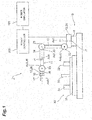
- a robot system 1 includes a robot 10, a robot simulator 100, and a robot controller 200.
- the robot 10 is a six-axis vertical articulated robot, for example, being configured to execute tasks for a workpiece 30 using a tool provided at a distal end portion of the robot.
- Various tasks can be executed by selecting a tool according to the content of the task.
- Specific task content examples include pick- and-place in which components are picked and arranged, spot welding of components, and arc welding of components.
- FIG. 1 illustrates the robot 10 configured to perform arc welding of individual components.
- the robot 10 includes a base 11, a rotating portion 12, a first arm 13, a second arm 14, a third arm 15, a distal end portion 16, and actuators 21 to 26.
- the base 11 is fixed to an installation surface.
- the rotating portion 12 is provided on the base 11 and can rotate about a vertical axis Ax1.
- a connecting portion between the base 11 and the rotating portion 12 will be referred to as a "joint J1”
- a rotation angle of the rotating portion 12 with respect to the base 11 will be referred to as an “angle of the joint J1”.
- the first arm 13 is connected to the rotating portion 12 and is swingable about an axis Ax2 orthogonal to the axis Ax1. Being orthogonal involves crossing away from one another like an overpass.
- joint J2 a connecting portion between the rotating portion 12 and the first arm 13
- angle of the joint J2 a swing angle of the first arm 13 with respect to the rotating portion 12
- the second arm 14 is connected to the distal end portion of the first arm 13 and is swingable about an axis Ax3 parallel to the axis Ax2.
- a connecting portion between the first arm 13 and the second arm 14 will be referred to as a "joint J3”
- the swing angle of the second arm 14 with respect to the first arm 13 will be referred to as an "angle of the joint J3”.
- the distal end portion of the second arm 14 can rotate about an axis Ax4 along the centerline of the second arm 14.
- joint J4 the connecting portion between a proximal end portion and the distal end portion of the second arm 14
- angle of the joint J4 the rotation angle of the distal end portion with respect to the proximal end portion of the second arm 14
- the third arm 15 is connected to a distal end portion of the second arm 14 and is swingable about an axis Ax5 orthogonal to the axis Ax4.
- a connecting portion between the second arm 14 and the third arm 15 will be referred to as a "joint J5"
- the swing angle of the third arm 15 with respect to the second arm 14 will be referred to as an "angle of the joint J5".
- the distal end portion 16 is connected to a distal end portion of the third arm 15, and the distal end portion 16 can rotate about an axis Ax6 along the centerline of the third arm 15.
- a connecting portion between the third arm 15 and the distal end portion 16 will be referred to as a "joint J6”
- the rotation angle of the distal end portion 16 with respect to the third arm 15 will be referred to as an "angle of the joint J6”.
- a tool 17 is provided at the distal end portion 16.
- the tool 17 is, for example, a torch for arc welding and is detachable.
- Each of the actuators 21 to 26 drives each of the joints J1 to J6 respectively using an electric motor as a power source, for example.
- the actuator 21 rotates the rotating portion 12 about the axis Ax1
- the actuator 22 swings the first arm 13 about the axis Ax2
- the actuator 23 swings the second arm 14 about the axis Ax3
- the actuator 24 rotates the distal end portion of the second arm 14 about the axis Ax4
- the actuator 25 swings the third arm 15 about the axis Ax5
- the actuator 26 rotates the distal end portion 16 about the axis Ax6.
- the workpiece 30 includes elements that can be an obstacle to the movement of the robot 10.
- the workpiece 30 includes a base component 31 and a plurality of components 32, 33, and 34 arranged on the component 31.
- the robot 10 performs arc welding of the components 32, 33, and 34 onto the component 31.
- each of the components 32, 33, and 34 can be an obstacle.
- the term "obstacle" does not represent one that constantly hinders the movement of the distal end portion 16, but represents one that can hinder the movement of the distal end portion 16 under a certain operating condition of the robot 10.
- peripheral apparatuses or jigs of the robot can also be obstacles, for example.
- the configuration of the robot 10 illustrated above is merely an example.
- the robot 10 may have any configuration as long as the position and posture of the distal end portion can be adjusted to a desired state.
- the robot 10 may be a seven-axis robot with one additional axis provided to the above-described configuration.
- the robot simulator 100 simulates a positional relationship between the robot 10 and the workpiece 30 based on model information of the robot 10 and the workpiece 30 and generates a path of the robot 10 based on a result of simulation.
- the path is information defining a movement route of the distal end portion 16 of the robot simulator 100 and the posture of the robot 10 (that is, the angles of the joints J1 to J6) when the distal end portion 16 is moved along the route.
- the robot controller 200 controls the robot 10 so as to move the distal end portion 16 along the above-described path (to operate the joints J1 to J6 in accordance with the above-described path).
- the robot simulator 100 and the robot controller 200 may be integrated.
- the function of the robot simulator 100 may be incorporated in the robot controller 200, or the function of the robot controller 200 may be incorporated in the robot simulator 100.
- the robot simulator 100 includes a main body 110 constituted with one or more computers, an input apparatus 191, and a monitor 192.
- the input apparatus 191 is an apparatus used for inputting information into the main body 110.
- the input apparatus 191 may be of any type as long as desired information can be input on the apparatus, and specific examples thereof include a keypad and a mouse.
- the monitor 192 is an apparatus used for displaying information output from the main body 110.
- the monitor 192 may be of any type as long as graphic display is possible on the monitor, and a specific example thereof is a liquid crystal panel.
- the input apparatus 191 and the monitor 192 may be integrated as a touchscreen having both an input function and a display function.
- the input apparatus 191 and the monitor 192 may be incorporated in the main body 110.
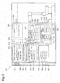
- the main body 110 includes as a functional configuration (hereinafter referred to as "functional modules”) a model storage module 111, a job storage module 112, a condition storage module 113, a path storage module 114, a main screen output module 115, an information acquisition module 120, an information processing module 130, and an image data output module 118.
- functional modules a functional configuration (hereinafter referred to as "functional modules") a model storage module 111, a job storage module 112, a condition storage module 113, a path storage module 114, a main screen output module 115, an information acquisition module 120, an information processing module 130, and an image data output module 118.
- the model storage module 111 stores model information related to the robot 10 and an obstacle in the vicinity of the robot 10.
- the model storage module 111 stores model information of the workpiece 30 as the model information related to the obstacle.
- the model information is three-dimensional surface data constituted with polygons, for example.
- the model information of the robot 10 and the workpiece 30 may be generated based on three-dimensional design data or may be generated based on measurement data by a three-dimensional measurement apparatus, or the like.
- the job storage module 112 stores at least one job that defines operation of the robot 10. As illustrated in FIG. 3 , each of the jobs includes a plurality of lines arranged in chronological order. Each of the lines includes information defining a target position and posture of the distal end portion 16 and necessity of generating a path with the preceding line. Paths obtained by known methods such as linear interpolation, circular interpolation, and joint angle interpolation are set beforehand between sequentially arranged lines (hereinafter referred to as "sections"). Hereinafter, this will be referred to as an "initial path".
- the condition storage module 113 stores path generation conditions.
- the condition storage module 113 stores a condition (hereinafter referred to as a "repetition condition") for regulating the number of times of generation of a path (candidate path).
- the repetition condition may be an upper limit value of the number of times of path generation, or may be the time for repeating path generation.
- the condition storage module 113 may further store an evaluation criterion for the generated path.
- the evaluation criterion for the path is used as a criterion for selecting which one of the plurality of paths generated with the number of times of generation satisfying the above-described repetition condition.
- Specific examples of the evaluation criterion of the path include: whether the movement time of the distal end portion 16 along the path is minimum; whether the total operation angle of the joints J1 to J6 during the movement of the distal end portion 16 along the path is minimum; whether the number of via-point (described below) of the path is minimum; and whether the power consumption of the actuators 21 to 26 in the movement of the distal end portion 16 along the path is minimum.
- the condition storage module 113 may also store an accessible distance of the obstacle to the robot 10, that is, the accessible distance of the robot 10 to the obstacle.
- the accessible distance is used in generation of an outer shell model described below.
- the condition storage module 113 may store a posture condition of the distal end portion 16 in the movement along the path.
- the posture condition may be a numerical value defining a unique posture angle of the distal end portion 16, or may be a numerical value range defining an upper limit value and a lower limit value of the posture angle of the distal end portion 16.
- the condition storage module 113 may store a movable range of the joints J1 to J6 in the movement of the distal end portion 16 along the path.
- the movable range of the joints J1 to J6 may be determined in any form.
- each of the movable range of the joints J1 to J6 may be a numerical value range of each of the angles of the joints J1 to J6, or may be a ratio to a movable range defined by hardware constraints (hereinafter referred to as "structural movable range").
- the path storage module 114 stores a generated path.
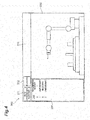
- FIG. 4 is a schematic diagram illustrating a main window.
- a main window 300 includes a menu bar 310, a job frame 320, and a drawing frame 330.
- the menu bar 310 includes buttons for invoking various functions of the robot simulator 100.
- the menu bar 310 includes a path generation support button 311 and a playback button 312.
- the path generation support button 311 is a button for invoking a path generation support function and enables operation input (for example, clicking or tapping) by the input apparatus 191.
- the playback button 312 is a button used for the playback of a moving image of the robot 10 according to a generated path, and enables operation input by the input apparatus 191.
- the job frame 320 displays a configuration of the job to be a path generation support target.
- the drawing frame 330 displays an image including an illustration of the robot 10 and an illustration of the workpiece 30.
- the information acquisition module 120 is configured to obtain at least input information (hereinafter referred to as "first input information") defining a start position and an end position of the operation of the robot 10.
- the "start position” includes a position of the distal end portion 16 at the start of the operation and the posture of the robot 10 (that is, the angles of the joints J1 to J6) when the distal end portion 16 is arranged at the position.
- the "end position” includes a position of the distal end portion 16 at the end of operation and the posture of the robot 10 when the distal end portion 16 is arranged at the position.
- the information acquisition module 120 may be configured to further obtain input information (hereinafter referred to as "second input information") for changing the position of a via-point (described below) of the generated path.
- second input information input information
- the information acquisition module 120 may be configured to further obtain at least one of input information (hereinafter referred to as "third input information”) defining the above-described repetition conditions, input information (hereinafter referred to as “fourth input information") defining the evaluation criterion of the path, input information (hereinafter referred to as “fifth input information”) defining the above-described accessible distance, input information (hereinafter referred to as “sixth input information”) defining the above-described posture condition, and input information (hereinafter referred to as " seventh input information”) defining the above-described movable range.
- the information acquisition module 120 includes as subdivided functional modules, a job specification acquisition module 121, an option input acquisition module122, and a correction input acquisition module 123.
- the job specification acquisition module 121 obtains information (hereinafter referred to as "job specifying information") specifying any of the jobs stored in the job storage module 112 from the input apparatus 191.
- job specifying information information specifying any of the jobs stored in the job storage module 112 from the input apparatus 191.
- the job includes a plurality of lines sequentially arranged in chronological order, and each of the lines includes information defining the target position and the posture of the distal end portion 16. Accordingly, specifying a job determines the start position and the end position of the operation of the robot 10 for each of the sections of the job.
- the first input information is not limited to the job specifying information.
- the job specification acquisition module 121 may obtain from the input apparatus 191 information directly specifying the start position and the end position.
- the option input acquisition module 122 obtains the above-described third input information to the seventh input information from the input apparatus 191 and writes the conditions determined by the obtained input information into the condition storage module 113.
- the correction input acquisition module 123 obtains from the input apparatus 191 input information for moving an index of a via-point (described below) on the image of the monitor 192 as an example of the above-described second input information.
- the information processing module 130 is configured to execute generation of a path for moving the distal end portion 16 from the start position to the end position while avoiding a collision between the robot 10 and the obstacle based on the first input information and the model information and execute generation of image data including an illustration of the obstacle and an index indicating the via-point of the path.
- the information processing module 130 may be configured to execute correction of the path so as to pass through the via-point after a position change based on the above-described second input information and execute generation of image data in which the position of the index has been changed based on the second input information.
- the information processing module 130 may be configured, in generation of a path, to execute repetition of generation of the path until the above-described repetition condition defined by the third input information is satisfied and execute selection of one path from among the generated plurality of paths.
- the information processing module 130 may be configured to select the one path in accordance with the above-described evaluation criterion defined by the fourth input information when selecting the one path from among the plurality of paths.
- the information processing module 130 may be configured to further execute generation of an outer shell model covering the robot 10 while maintaining the above-described accessible distance defined based on the fifth input information, and generate a path for moving the distal end portion 16 from the start position to the end position while avoiding a collision between the outer shell model and the obstacle in generation of the path.
- the information processing module 130 may configured to generate an outer shell model covering the obstacle while maintaining the above-described accessible distance in addition to the outer shell model covering the robot 10 and may configured to generate a path for moving the distal end portion 16 from the start position to the end position while avoiding a collision between the outer shell model of the robot 10 and the outer shell model of the obstacle.
- the information processing module 130 may be configured to generate the path such that the posture of the distal end portion 16 satisfies the above-described posture condition defined by the sixth input information, and may be configured to generate the path such that the operation angles of the joints J1 to J6 are within movable ranges defined by the seventh input information.
- the information processing module 130 includes as subdivided functional modules, an outer shell model generation module 131, a start-end position setting module 132, a path generation module 133, an image data generation module 134, a via-point correction module 135, a path generation propriety determination module 136, a corrected path generation module 137, and a moving image data generation module 138.
- the outer shell model generation module 131 generates an outer shell model covering the robot 10 while maintaining the above-described accessible distance stored in the condition storage module 113 and writes the generated model into the model storage module 111.
- the outer shell model generation module 131 may further generate an outer shell model covering obstacles (for example, components 32, 33, and 34) while maintaining the above-described accessible distance and may write the generated model into the model storage module 111.
- the start-end position setting module 132 obtains information of a job (hereinafter referred to as "specified job") corresponding to the specification obtained by the job specification acquisition module 121 from the job storage module 112 and defines a start position and an end position of the section as a path generation target based on the information.
- the path generation module 133 obtains information of the start position and the end position of the section as a target of path generation from the start-end position setting module 132, and then obtains the model information from the model storage module 111, so as to generate a path for moving the distal end portion 16 from the start position to the end position while avoiding the collision between the robot 10 and the obstacle.
- the path generation module 133 generates a path from the start position to the end position via at least one via-point so as to satisfy the following conditions i) to iii). Portions between the start position and the via-point, between the individual via-points, and between the via-point and the end position are interpolated by known methods such as linear interpolation, circular interpolation, and joint angle interpolation.
- the path generation module 133 repeats generation of the path until the above-described repetition conditions stored in the condition storage module 113 are satisfied and obtains a plurality of paths, and thereafter, the path generation module 133 selects one path from among the plurality of paths in accordance with the above-described evaluation criterion stored in the condition storage module 113 and applies the selected path to the specified job stored in the job storage module 112.
- the above-described initial path in the path generation target section among the specified jobs is modified to a path that satisfies the above-described conditions i) to iii).
- the path generation module 133 After generating the path, the path generation module 133 corrects the path so as to pass through the via-point after a position change based on the second input information.
- the image data generation module 134 Based on the model information stored in the model storage module 111 and the modified job stored in the job storage module 112 (job after path modification by the path generation module 133), the image data generation module 134 generates image data including an illustration of the robot 10, an illustration of the workpiece 30, an index indicating a via-point of the path, and a line indicating the path.
- the image data may be, for example, three-dimensional image data constituted with polygons and vectors, or two-dimensional diagrammatic data.
- the image data generation module 134 After generating the above-described image data, the image data generation module 134 generates image data in which the position of the above-described index has been changed based on the second input information.
- the via-point correction module 135 changes the position of the via-point in the three-dimensional space in accordance with the position change of the above-described index.
- the path generation propriety determination module 136 determines whether it is possible to generate a path that passes through the changed via-point. For example, the path generation propriety determination module 136 determines whether the changed via-point satisfies the above-described conditions i) to iii).
- the corrected path generation module 137 corrects the path so as to pass through the above-described changed via-point and applies the corrected path to the above-described modified job stored in the job storage module 112.
- the moving image data generation module 138 Based on the model information stored in the model storage module 111 and the modified job stored in the job storage module 112, the moving image data generation module 138 generates moving image data in a case where the robot 10 is operated so as to move the distal end portion 16 along the path.
- the image data output module 118 outputs the image data generated by the image data generation module 134 or the moving image data generated by the moving image data generation module 138 to the monitor 192.
- FIG. 5 is a block diagram illustrating a hardware configuration of the main body 110.
- the main body 110 includes a circuit 150, and the circuit 150 includes one or more processors 151, a storage module 152, and input/output ports 155 and 156.
- the storage module 152 includes a memory 153 and a storage 154.
- the storage 154 records programs used to configure each of the above-described functional modules of the main body 110.
- the storage 154 may be of any type as long as it is a computer-readable storage. Specific examples include a hard disk, a nonvolatile semiconductor memory, a magnetic disk, and an optical disk.
- the memory 153 temporarily stores the program loaded from the storage 154, calculation results of the processor 151, or the like.
- the processor 151 executes programs in cooperation with the memory 153, thereby constituting each of the functional modules.
- the input/output port 155 inputs and outputs electric signals to/from the input apparatus 191 in accordance with a command from the processor 151.
- the input/output port 156 inputs and outputs an electric signal to/from the monitor 192 in accordance with a command from the processor 151.
- step S01 the robot simulator 100 first executes step S01.
- step S01 the main screen output module 115 waits for an operation input to the path generation support button 311.
- step S02 the job specification acquisition module 121 outputs data for displaying the job specifying window to the monitor 192.
- FIG. 7 is a schematic diagram illustrating a screen displaying a job specifying window.
- the job specifying window 400 includes a job list 401, an option button 402, and a path generation button 403.
- the job list 401 displays a list of jobs stored in the job storage module 112. By inputting into the input apparatus 191, it is possible to select any of the jobs displayed in the job list 401.
- the option button 402 is a button for invoking an input screen of an optional condition for path generation and enables operation input by the input apparatus 191.
- the path generation button 403 is a button for requesting execution of path generation for one job selected in the job list 401 and enables operation input by the input apparatus 191.
- step S03 the job specification acquisition module 121 confirms the presence or absence of an operation input to the path generation button 403.
- step S04 the option input acquisition module 122 confirms the presence or absence of an operation input to the option button 402.
- step S04 determines that there is no operation input to the option button 402
- the robot simulator 100 returns the processing to step S03. Thereafter, the robot simulator 100 waits for an operation input to any of the option button 402 and the path generation button 403.
- step S05 the option input acquisition module 122 displays the option setting window.
- FIG. 8 is a schematic diagram illustrating a screen displaying the option setting window.
- an option setting window 500 includes setting menus 510, 520, 530, 540, 550, and 560, and an OK button 590.
- the setting menu 510 is a menu for setting the path search finish condition (the above-described repetition condition), and includes input boxes 512 and 513 and a radio button 511.
- the input box 512 is a portion for inputting the number of search paths (the above-described repetition number) and enables an input of numerical value by the input apparatus 191.
- the input box 513 is a portion for inputting the search time (the above-described repetition time), and enables an input of a numerical value by the input apparatus 191.
- the radio button 511 is a portion for selecting which of the number of search paths and the search time is to be determined and enables selection input by the input apparatus 191.
- the input information to the setting menu 510 corresponds to an example of the above-described third input information.
- the setting menu 520 is a menu for setting path selection criterion (the above-described evaluation criterion) and includes an input box 521.
- the input box 521 is a portion for inputting selection criterion, and enables selection input by the input apparatus 191.
- the input box 521 is configured to enable inputting any of "minimum cycle time", “minimum joint operation angle”, “minimum number of via-points” or “minimum power consumption” by a pull-down system.
- the above-described evaluation criterion is set so as to select a path achieving a minimum time for movement of the distal end portion 16 along the path.
- the above-described evaluation criterion is set so as to select a path achieving a minimum total operating angle of the joints J1 to J6 in the movement of the distal end portion 16 along the path.
- the above-described evaluation criterion is set so as to select the path achieving the minimum number of via-points (described below) of the path.
- the evaluation criterion is set so as to select the path achieving the minimum power consumption of the actuators 21 to 26 in a movement of the distal end portion 16 along the path.
- the input information to the setting menu 520 corresponds to an example of the above-described fourth input information.
- the setting menu 530 is a menu for setting the moving speed of the distal end portion 16 in a generated path and includes an input box 531.
- the input box 531 is a portion for inputting a setting value of the moving speed, and enables an input of a numerical value by the input apparatus 191.
- the setting menu 540 is a menu for setting simplification conditions (generation conditions of the above-described outer shell model) and includes input boxes 541 and 542.
- the input box 541 is a portion for inputting a margin amount (the above-described accessible distance) and enables an input of a numerical value by the input apparatus 191.
- the input box 542 is a portion for inputting the fineness and enables an input of a numerical value by the input apparatus 191.
- the fineness represents the degree of simplification of the outer shell model. Specific examples of the fineness include a numerical value indicating the degree of subdivision of the surface of the outer shell model.
- the numerical value indicating the degree of subdivision may be represented by the ratio to the surface of the model of the robot 10.
- the input information to the input box 541 corresponds to the above-described fifth input information.
- the setting menu 550 is a menu for setting the above-described posture condition and includes input boxes 551, 552, and 553.
- the input boxes 551, 552, and 553 are portions for inputting a tilt angle around the X-axis, a tilt angle around the Y-axis, and a tilt angle around the Z-axis, respectively, and each of the boxes enables an input of a numerical value by the input apparatus 191.
- the X-, Y-, and Z-axes are predetermined coordinate axes.
- the input information to the setting menu 550 corresponds to the above-described sixth input information.
- the setting menu 560 is a menu for setting conditions for regulating a path search range (spatial search range), and includes input boxes 561, 562, 563, 564, 565, and 566, and input boxes 571, 572, 573, 574, 575, and 576.
- Input boxes 561, 562, 563, 564, 565 and 566 are portions for inputting values defining the movable ranges of the joints J1 to J6, and each of the boxes enables an input of a numerical value by the input apparatus 191.
- ranges obtained by multiplying the structural movable ranges of the joints J1 to J6 by the above-described usage rates are individually set as the above-described movable ranges.
- the input boxes 571, 572, 573, 574, 575, and 576 are portions for inputting values defining a movable region of the distal end portion 16, and each of the boxes enables an input of a numerical value by the input apparatus 191.
- the input boxes 571 and 572 enables an input of each of a lower limit and an upper limit of the X-axis coordinate, respectively
- the input boxes 573 and 574 enables an input of each of a lower limit and an upper limit of the Y-axis coordinate, respectively
- the input boxes 575 and 576 enables an input of each of a lower limit and an upper limit of the Z-axis coordinate, respectively.
- the region defined by these input values is set as the movable region of the distal end portion 16.
- the input information to the input boxes 561 to 566 corresponds to the above-described seventh input information.
- the input information to the input boxes 571 to 576 also corresponds to the above-described seventh input information.
- the reason is that regulating the movable region of the distal end portion 16 indirectly regulates the movable ranges of the joints J1 to J6.
- the OK button 590 is a button for requesting registration of the content of input to the setting menus 510, 520, 530, 540, 550, and 560, and enables an operation input by the input apparatus 191.
- step S06 the option input acquisition module 122 waits for an operation input to the OK button 590.
- step S07 the option input acquisition module 122 obtains input information for the setting menus 510, 520, 530, 540, 550, and 560 and writes the obtained information into the condition storage module 113 as path generation conditions.
- step S08 the option input acquisition module 122 outputs a command to set the option setting window 500 to a non-display mode to the monitor 192.
- step S09 the job specification acquisition module 121 obtains a job selection status in the job list 401 as the above-described job specifying information.
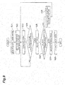
- step S10 the information processing module 130 generates a path in accordance with the condition stored in the condition storage module 113, for the section as a path generation target among the sections of the specified jobs (jobs specified by the job specifying information). Details of the processing content in step S10 will be described below. This completes the procedure from invocation of the path generation support function to path generation.
- step S21 the outer shell model generation module 131 generates an outer shell model covering the robot 10 while maintaining the above-described accessible distance stored in the condition storage module 113, and writes the generated model into the model storage module 111.
- the outer shell model generation module 131 generates the outer shell model in accordance with the above-described fineness such that the minimum value of the interval between the model of the robot 10 and the outer shell model is the above-described accessible distance or more.
- step S22 the start-end position setting module 132 obtains the information related to the above-described specified job from the job storage module 112, and determines the start position and the end position of the section as a path generation target based on the obtained information.
- step S23 the path generation module 133 obtains the information related to the start position and the end position from the start-end position setting module 132, and obtains model information from the model storage module 111.
- the path generation module 133 then generates a path for moving the distal end portion 16 from the start position to the end position while avoiding a collision between the robot 10 and the obstacle, and writes the generated path into the job storage module 112 as a candidate path. More specifically, the path generation module 133 generates the path to satisfy the above-described conditions i) to iii).
- the path generation module 133 generates a via-point that satisfies the above-described conditions i) to iii), and repeats path correction over the entire path so as to set the path to pass through the via-point until the conditions i) to iii) are satisfied.
- a more detailed method is disclosed in Japanese Patent No. 4103057 , for example.
- step S24 the path generation module 133 confirms whether the above-described repetition condition stored in the condition storage module 113 is satisfied.
- step S24 In a case where it is determined in step S24, that the above-described repetition condition is not satisfied, the robot simulator 100 returns the processing to step S23. Thereafter, generation and writing of the candidate path are repeated until the above-described repetition condition is satisfied, accumulating a plurality of candidate paths in the path storage module 114.
- step S25 the path generation module 133 selects one path from among the above-described plurality of candidate paths in accordance with the above-described evaluation criterion stored in the condition storage module 113, and applies the selected path to the specified job stored in the job storage module 112. That is, the via-point of the relevant path is inserted into the section as the path generation target among the specified jobs.
- the above-described initial path in the section is modified to the path that satisfies the above-described conditions i) to iii).
- step S26 the start-end position setting module 132 confirms whether path generation is completed for all the sections as path generation targets.
- step S27 the start-end position setting module 132 selects any of the sections as a target of path generation, and changes the start position and the end position accordingly. Thereafter, the robot simulator 100 returns the processing to step S23. Thereafter, path generation and modification of the specified job according to the generated path are repeated until path generation is completed for all the sections as path generation targets. Accordingly, hereinafter, the specified job with the modified initial path will be referred to as a "modified job" for all the sections as path generation targets.
- step S28 based on the model information stored in the model storage module 111 and the modified job stored in the job storage module 112, the image data generation module 134 generates image data including an illustration of the robot 10, an illustration of the outer shell model, an illustration of the workpiece 30, an index indicating a via-point of the path, and a line indicating the path.
- step S29 the image data output module 118 obtains the image data generated in step S29 from the image data generation module 134, and outputs the obtained image data to the monitor 192. This completes the above-described step S10.
- FIG. 10 is a schematic diagram illustrating an image displayed on the monitor 192 in step S29.
- the drawing frame 330 displays an outer shell model M3 in addition to a model M1 of the robot 10 and a model M2 of the workpiece 30. Furthermore, the drawing frame 330 displays an index P1 indicating a start position, indices P11 to P15 indicating via-points, an index P2 indicating an end position, and a line RT1 starting from the index P1 of the starting position to the index P2 of the end position through the indices P11 to P15 of the via-points. In a state where the indices P11 to P15 are displayed, any of the indices P11 to P15 can be selected by an input by the input apparatus 191. While FIG. 10 two-dimensionally displays the display content in the drawing frame 330 for ease of understanding, it is actually possible to display a three-dimensional image in the drawing frame 330.
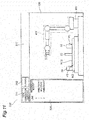
- FIG. 11 is a diagram for comparison, illustrating an image displaying the above-described initial path without performing the above-described steps S23 to S27.
- FIG. 11 displays a line RT2 starting from the index P1 to the index P2 through the components 32 and 33.
- the line RT1 in FIG. 10 starts from the index P1 to reach the index P2 by bypassing the components 32 and 33, and operating the robot 10 in the path indicated by the line RT1 would not cause the collision between the robot 10 and the components 32 and 33.
- the path generation module 133 may first generate a copy of the specified job and may then modify the copy.
- step S31 the correction input acquisition module 123 confirms the presence or absence of an input of selecting an index of any of the via-points.
- step S32 the correction input acquisition module 123 confirms whether there is an input of completing path correction (hereinafter referred to as a "completion input") to the input apparatus 191.
- the completion input include an operation input to the playback button 312, an input of closing the main window 300.
- step S32 In a case where it is determined in step S32 that there is no completion input, the robot simulator 100 returns the processing to step S31. Thereafter, the robot simulator 100 waits for an input of selecting an index or a completion input.
- step S33 the correction input acquisition module 123 outputs a command of adding an edit mark EM (refer to FIG. 13 ) to the selected index to the image data output module 118, and the image data output module 118 outputs the image data corresponding to the command to the monitor 192.
- the index to which the edit mark EM is attached will be referred to as an "active index”.
- the active index can be moved by operation input (for example, input by dragging) by the input apparatus 191.
- step S34 the correction input acquisition module 123 confirms whether the operation input of moving the active index has been started.
- step S35 the information processing module 130 executes processing of correcting the path in accordance with the movement of the active index. Details of the processing content in step S35 will be described below.
- step S36 the correction input acquisition module 123 confirms whether the operation input of moving the active index has been completed.
- step S36 In a case where it is determined in step S36, that the operation input of moving the active index has not been completed, the robot simulator 100 returns the processing to step S35. Thereafter, path correction according to the movement of the active index is repeated until the operation input of moving the active index is completed.
- step S36 determines that the operation input of moving the active index has been completed.
- step S34 determines that the operation input of moving the active index has not been started.
- step S37 the correction input acquisition module 123 confirms the presence or absence of an operation input of selecting an index of another via-point.
- step S38 the correction input acquisition module 123 outputs a command of changing the position of the edit mark EM to the position of the newly selected index to the image data output module 118, and then, the image data output module 118 outputs the image data corresponding to this command to the monitor 192.
- step S39 the robot simulator 100 executes step S39.
- the robot simulator 100 executes step S39 without executing step S38.
- the correction input acquisition module 123 confirms the presence or absence of the above-described completion input.
- step S39 In a case where it is determined in step S39 that there is no completion input, the robot simulator 100 returns the processing to step S33. Thereafter, path correction according to the movement of the active index and the change in the active index are repeated in accordance with the operation input to the input apparatus 191 until the completion input is performed. In a case where it is determined in any of steps S32 and S39 that there is a completion input, the robot simulator 100 completes the processing.
- step S41 the correction input acquisition module 123 obtains input information for moving the active index.
- step S42 the correction input acquisition module 123 sets a movement amount of the active index in accordance with the information obtained in step S41.
- step S43 the via-point correction module 135 changes the position of the via-point in accordance with the movement amount of the active index.
- step S44 the path generation propriety determination module 136 determines propriety of generation of a path that passes through the changed via-point (via-point whose position has been changed in step S43). For example, the path generation propriety determination module 136 determines whether the changed via-point satisfies the above-described conditions i) to iii).
- step S45 the corrected path generation module 137 regenerates the path so as to pass through the changed via-point, and applies the path to the above-described modified job stored in the job storage module 112. In other words, the via-point of the path is inserted into the section as the path generation target among the modified jobs.
- step S46 the position of the active index is changed with the movement amount set in step S43, the position of the edit mark EM is also changed accordingly, and furthermore, the image data generation module 134 regenerates the image data with the path line changed so as to pass through the changed active index.
- step S47 the image data generation module 134 generates image data notifying that path generation is unavailable (hereinafter referred to as "image data notifying unavailability").
- image data notifying unavailability may be any image as long as unavailability of path generation is visually recognizable.
- the image data generation module 134 may generate image data with the color of the robot 10 or the background color of the drawing frame 330, or the like, being changed from that of image data in a case where the path generation is available, as the image data notifying unavailability.
- step S48 the image data output module 118 obtains the image data generated in one of step S46 and step S47 from the image data generation module 134, and outputs the obtained image data to the monitor 192. This completes the above-described step S35.
- FIG. 15 is a schematic diagram illustrating an image displayed on the monitor 192 in step S48, illustrating a case where the position of the index P 13 in FIG. 13 has been changed and the line RT1 of the path has been changed accordingly.
- step S51 the moving image data generation module 138 waits for an operation input to the playback button 312.
- step S52 the moving image data generation module 138 obtains angles of the joints J1 to J6 corresponding to the job start position from the job storage module 112.
- the angles of the joints J1 to J6 obtained by the moving image data generation module 138 will be referred to as "simulation angles”.
- step S53 based on the model information stored in the model storage module 111 and the job stored in the job storage module 112, the moving image data generation module 138 generates image data including a diagram of the robot 10 to which the simulation angle is applied, a diagram of the workpiece 30, the index indicating the via-point of the path, and the line indicating the path.
- step S54 the image data output module 118 obtains the image data generated in step S53 from the moving image data generation module 138, and outputs the obtained image data to the monitor 192.
- step S55 the moving image data generation module 138 confirms whether the distal end portion 16 of the robot 10 to which the simulation angle is applied has reached the end position of the job.
- step S55 the robot simulator 100 executes step S56.
- step S56 the moving image data generation module 138 obtains angles of the joints J1 to J6 corresponding to a succeeding position on the path (for example, the position after passage of a predetermined time) from the job storage module 112.
- the robot simulator 100 returns the processing to step S53. Thereafter, the position change of the distal end portion 16 along the path, the corresponding simulation angle change in the joints J1 to J6, and generation and output of image data according to the changed simulation angle are repeated until the distal end portion 16 reaches the end position of the job.
- the operation of the robot 10 in the case of moving the distal end portion 16 along the path is displayed as a moving image (refer to FIG. 17 ).
- the robot simulator 100 completes the moving image playback processing. By displaying the operation of the robot 10 according to the job including the generated path as a moving image, it is possible to confirm the validity of the generated path with further clarity.
- the robot simulator 100 includes: the model storage module 111 storing model information related to the robot 10 and an obstacle in the vicinity of the robot 10; the information acquisition module 120 configured to obtain first input information defining a start position and an end position of operation of the robot 10; and the information processing module 130 configured to execute generation of a path for moving the distal end portion 16 of the robot 10 from the start position to the end position while avoiding a collision between the robot 10 and the obstacle based on the first input information and the model information and execute generation of image data including an illustration of the obstacle and an index indicating a via-point of the path.
- a path for moving the distal end portion 16 of the robot 10 from the start position to the end position while avoiding a collision between the robot 10 and the obstacle is automatically generated.
- image data including the illustration of the obstacle and the index indicating the via-point of the path is generated, it is possible to visually illustrate the relationship between the obstacle and the automatically generated path using the image data. This makes it possible to facilitate determination of path adoptability, fine adjustment of a path, or the like. Accordingly, this achieves an effect in facilitating teaching of operation of the robot 10.
- the information acquisition module 120 is configured to further obtain the second input information for changing the position of the via-point
- the information processing module 130 may be configured to further execute regeneration of the path so as to pass through the via-point after a position change based on the second input information and generation of image data in which the position of the index has been changed based on the second input information.
- the path can be adjusted by intuitive operation of moving the via-point on the image.
- the image is updated after the position of the via-point is changed, it is possible to adjust the path while checking the state of the adjusted path. This achieves further effect in facilitating the teaching of operation of the robot 10.
- the information acquisition module 120 may be configured to further obtain the third input information defining a condition for regulating the number of times of path generation, and the information processing module 130 may be configured, in generation of the path, to execute repetition of generation of the path until the condition defined by the third input information is satisfied and execute selection of one path from among the plurality of generated paths.
- the information processing module 130 may be configured, in generation of the path, to execute repetition of generation of the path until the condition defined by the third input information is satisfied and execute selection of one path from among the plurality of generated paths.
- the information acquisition module 120 may be configured to further obtain fourth input information defining the evaluation criterion of the path, and the information processing module 130 may be configured to select one path in accordance with the evaluation criterion defined by the fourth input information in the selection of the one path from among the plurality of paths.
- the evaluation criterion of the path it is possible to generate a path that is further focused on user's requests. This achieves further effect in facilitating the teaching of operation of the robot 10.
- the information acquisition module 120 may be configured to further obtain fifth input information defining an accessible distance to the robot 10, and the information processing module 130 may be configured to further execute generation of an outer shell model covering the robot 10 while maintaining the accessible distance determined based on the fifth input information and generate a path for moving the distal end portion 16 from the start position to the end position while avoiding a collision between the outer shell model and the obstacle in generation of the path.
- the information processing module 130 may be configured to further execute generation of an outer shell model covering the robot 10 while maintaining the accessible distance determined based on the fifth input information and generate a path for moving the distal end portion 16 from the start position to the end position while avoiding a collision between the outer shell model and the obstacle in generation of the path.
- an interval corresponding to at least the accessible distance is maintained between the robot 10 and the obstacle. This makes it possible to allow a certain degree of deviation between a track in which the distal end portion 16 of the robot 10 actually moves and the path. It is also possible to simplify the shape of the outer shell model and to enhance the path generation speed. This
- the information acquisition module 120 may be configured to further obtain sixth input information defining the posture condition of the distal end portion 16 of the robot 10, and the information processing module 130 may be configured to generate the path such that the posture of the distal end portion 16 satisfies the posture condition defined by the sixth input information in generation of the path. This makes it possible to generate a path while satisfying the posture condition desired by the user. This achieves further effect in facilitating the teaching of operation of the robot 10.
- the information acquisition module 120 may be configured to further obtain seventh input information defining a movable ranges of the joints J1 to J6 of the robot 10, and the information processing module 130 may be configured to generate a path such that the operation angles of the joints J1 to J6 satisfy the movable range defined by the seventh input information in generation of the path.
- the information processing module 130 may be configured to generate a path such that the operation angles of the joints J1 to J6 satisfy the movable range defined by the seventh input information in generation of the path.
- the movable ranges of the joints J1 to J6 to be smaller than the structural movable ranges, it is possible to generate a path with room for further change in the joint angles. This further facilitates the task of finely adjusting the path after generating the path. This achieves further effect in facilitating the teaching of operation of the robot 10.
Landscapes
- Engineering & Computer Science (AREA)
- Robotics (AREA)
- Mechanical Engineering (AREA)
- Physics & Mathematics (AREA)
- Automation & Control Theory (AREA)
- General Physics & Mathematics (AREA)
- Theoretical Computer Science (AREA)
- Human Computer Interaction (AREA)
- Manufacturing & Machinery (AREA)
- Computer Hardware Design (AREA)
- Evolutionary Computation (AREA)
- Geometry (AREA)
- General Engineering & Computer Science (AREA)
- Manipulator (AREA)
- Numerical Control (AREA)
Abstract
Description
- The present disclosure relates to a robot simulator, a robot system, and a simulation method.
- Japanese Unexamined Patent Publication No.
2015-202523 - An object of the present disclosure is to provide a robot simulator, a robot system and a simulation method effective for facilitating teaching of operation of a robot.
- A robot simulator according to one aspect of the present disclosure includes: a model storage module storing model information related to a robot and an obstacle in the vicinity of the robot; an information acquisition module configured to obtain first input information defining a start point (start position) and an end point (end position) of operation of the robot; and an information processing module configured to execute generation of a path for moving a distal end portion of the robot from the start position to the end position between two teaching points while avoiding a collision between the robot and the obstacle based on the first input information and the model information and execute generation of image data including an illustration of the obstacle and an index indicating a via-point of the path.
- A robot system according to another aspect of the present disclosure includes the above-described robot simulator, a robot, and a robot controller configured to control the robot so as to move the distal end portion along the path.
- A simulation method according to still another aspect of the present disclosure is a simulation method using a robot simulator, the method including: storing model information related to a robot and an obstacle in the vicinity of the robot; obtaining first input information defining at least two teaching points toward a start position and an end position of operation of the robot; generating a path for moving the distal end portion of the robot from the start position to the end position between the two teaching points while avoiding a collision between the robot and the obstacle based on the first input information and the model information; and generating image data including an illustration of the obstacle and an index indicating a via-point of the path.
- According to the present disclosure, it is possible to provide a robot simulator, a robot system and a simulation method effective for facilitating teaching of operation of a robot.
-
-
FIG. 1 is a schematic diagram illustrating an entire configuration of a robot system; -
FIG. 2 is a block diagram illustrating a functional configuration of a robot simulator; -
FIG. 3 is a table illustrating job content. -
FIG 4 is a schematic diagram illustrating a main window; -
FIG. 5 is a block diagram illustrating a hardware configuration of the robot simulator; -
FIG. 6 is a flowchart illustrating a procedure from invocation of a path generation support function to path generation; -
FIG. 7 is a schematic diagram illustrating a screen displaying a job specifying window; -
FIG. 8 is a schematic diagram illustrating a screen displaying an option setting window; -
FIG. 9 is a flowchart illustrating a detailed procedure of path generation; -
FIG. 10 is a schematic diagram illustrating a screen displaying generated paths; -
FIG. 11 is a schematic diagram illustrating a screen displaying a path connecting a start position and an end position by a straight line; -
FIG. 12 is a flowchart illustrating a procedure from index selection to path correction; -
FIG. 13 is a schematic diagram illustrating a screen displaying edit marks of via-points; -
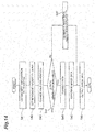
FIG. 14 is a flowchart illustrating a detailed procedure of path correction; -
FIG. 15 is a schematic diagram illustrating a screen displaying the corrected path; -
FIG. 16 is a flowchart illustrating a procedure of moving image playback processing; and -
FIG. 17 is a schematic diagram illustrating a screen during playback of a moving image. - Hereinafter, embodiments will be described in detail with reference to the drawings. In the description, same reference numerals will be used for same elements or elements having a same function, and redundant description will be omitted. A robot system according to the present embodiment is a system that automates various tasks such as machining and assembly by causing a robot to execute operation taught by an operator.
- As illustrated in
FIG. 1 , arobot system 1 includes arobot 10, arobot simulator 100, and arobot controller 200. Therobot 10 is a six-axis vertical articulated robot, for example, being configured to execute tasks for aworkpiece 30 using a tool provided at a distal end portion of the robot. Various tasks can be executed by selecting a tool according to the content of the task. Specific task content examples include pick- and-place in which components are picked and arranged, spot welding of components, and arc welding of components.FIG. 1 illustrates therobot 10 configured to perform arc welding of individual components. - The
robot 10 includes abase 11, a rotating portion 12, afirst arm 13, asecond arm 14, a third arm 15, adistal end portion 16, and actuators 21 to 26. - The
base 11 is fixed to an installation surface. The rotating portion 12 is provided on thebase 11 and can rotate about a vertical axis Ax1. Hereinafter, a connecting portion between thebase 11 and the rotating portion 12 will be referred to as a "joint J1", and a rotation angle of the rotating portion 12 with respect to thebase 11 will be referred to as an "angle of the joint J1". - The
first arm 13 is connected to the rotating portion 12 and is swingable about an axis Ax2 orthogonal to the axis Ax1. Being orthogonal involves crossing away from one another like an overpass. Hereinafter, a connecting portion between the rotating portion 12 and thefirst arm 13 will be referred to as "joint J2", and a swing angle of thefirst arm 13 with respect to the rotating portion 12 will be referred to as an "angle of the joint J2". - The
second arm 14 is connected to the distal end portion of thefirst arm 13 and is swingable about an axis Ax3 parallel to the axis Ax2. Hereinafter, a connecting portion between thefirst arm 13 and thesecond arm 14 will be referred to as a "joint J3", and the swing angle of thesecond arm 14 with respect to thefirst arm 13 will be referred to as an "angle of the joint J3". The distal end portion of thesecond arm 14 can rotate about an axis Ax4 along the centerline of thesecond arm 14. Hereinafter, the connecting portion between a proximal end portion and the distal end portion of thesecond arm 14 will be referred to as a "joint J4", and the rotation angle of the distal end portion with respect to the proximal end portion of thesecond arm 14 will be referred to as an "angle of the joint J4". - The third arm 15 is connected to a distal end portion of the
second arm 14 and is swingable about an axis Ax5 orthogonal to the axis Ax4. Hereinafter, a connecting portion between thesecond arm 14 and the third arm 15 will be referred to as a "joint J5", and the swing angle of the third arm 15 with respect to thesecond arm 14 will be referred to as an "angle of the joint J5". - The
distal end portion 16 is connected to a distal end portion of the third arm 15, and thedistal end portion 16 can rotate about an axis Ax6 along the centerline of the third arm 15. Hereinafter, a connecting portion between the third arm 15 and thedistal end portion 16 will be referred to as a "joint J6", and the rotation angle of thedistal end portion 16 with respect to the third arm 15 will be referred to as an "angle of the joint J6". Atool 17 is provided at thedistal end portion 16. Thetool 17 is, for example, a torch for arc welding and is detachable. - Each of the actuators 21 to 26 drives each of the joints J1 to J6 respectively using an electric motor as a power source, for example. Specifically, the actuator 21 rotates the rotating portion 12 about the axis Ax1, the
actuator 22 swings thefirst arm 13 about the axis Ax2, theactuator 23 swings thesecond arm 14 about the axis Ax3, theactuator 24 rotates the distal end portion of thesecond arm 14 about the axis Ax4, theactuator 25 swings the third arm 15 about the axis Ax5, and theactuator 26 rotates thedistal end portion 16 about the axis Ax6. - By adjusting the angles of the joints J1 to J6, it is possible to freely adjust the position and posture of the
tool 17 of thedistal end portion 16 in accordance with theworkpiece 30. - The
workpiece 30 includes elements that can be an obstacle to the movement of therobot 10. For example, theworkpiece 30 includes abase component 31 and a plurality ofcomponents component 31. For example, therobot 10 performs arc welding of thecomponents component 31. When moving thetool 17 from one weld to another weld, each of thecomponents distal end portion 16, but represents one that can hinder the movement of thedistal end portion 16 under a certain operating condition of therobot 10. In addition to components of the workpiece, peripheral apparatuses or jigs of the robot can also be obstacles, for example. - The configuration of the
robot 10 illustrated above is merely an example. Therobot 10 may have any configuration as long as the position and posture of the distal end portion can be adjusted to a desired state. For example, therobot 10 may be a seven-axis robot with one additional axis provided to the above-described configuration. - The
robot simulator 100 simulates a positional relationship between therobot 10 and theworkpiece 30 based on model information of therobot 10 and theworkpiece 30 and generates a path of therobot 10 based on a result of simulation. The path is information defining a movement route of thedistal end portion 16 of therobot simulator 100 and the posture of the robot 10 (that is, the angles of the joints J1 to J6) when thedistal end portion 16 is moved along the route. - The
robot controller 200 controls therobot 10 so as to move thedistal end portion 16 along the above-described path (to operate the joints J1 to J6 in accordance with the above-described path). - The
robot simulator 100 and therobot controller 200 may be integrated. For example, the function of therobot simulator 100 may be incorporated in therobot controller 200, or the function of therobot controller 200 may be incorporated in therobot simulator 100. - Subsequently, a configuration of the
robot simulator 100 will be described in detail. As illustrated inFIG. 2 , therobot simulator 100 includes amain body 110 constituted with one or more computers, aninput apparatus 191, and amonitor 192. - The
input apparatus 191 is an apparatus used for inputting information into themain body 110. Theinput apparatus 191 may be of any type as long as desired information can be input on the apparatus, and specific examples thereof include a keypad and a mouse. Themonitor 192 is an apparatus used for displaying information output from themain body 110. Themonitor 192 may be of any type as long as graphic display is possible on the monitor, and a specific example thereof is a liquid crystal panel. Note that theinput apparatus 191 and themonitor 192 may be integrated as a touchscreen having both an input function and a display function. Moreover, theinput apparatus 191 and themonitor 192 may be incorporated in themain body 110. - The
main body 110 includes as a functional configuration (hereinafter referred to as "functional modules") amodel storage module 111, ajob storage module 112, acondition storage module 113, apath storage module 114, a mainscreen output module 115, aninformation acquisition module 120, aninformation processing module 130, and an imagedata output module 118. - The
model storage module 111 stores model information related to therobot 10 and an obstacle in the vicinity of therobot 10. For example, themodel storage module 111 stores model information of theworkpiece 30 as the model information related to the obstacle. The model information is three-dimensional surface data constituted with polygons, for example. The model information of therobot 10 and theworkpiece 30 may be generated based on three-dimensional design data or may be generated based on measurement data by a three-dimensional measurement apparatus, or the like. - The
job storage module 112 stores at least one job that defines operation of therobot 10. As illustrated inFIG. 3 , each of the jobs includes a plurality of lines arranged in chronological order. Each of the lines includes information defining a target position and posture of thedistal end portion 16 and necessity of generating a path with the preceding line. Paths obtained by known methods such as linear interpolation, circular interpolation, and joint angle interpolation are set beforehand between sequentially arranged lines (hereinafter referred to as "sections"). Hereinafter, this will be referred to as an "initial path". - Returning to
FIG. 2 , thecondition storage module 113 stores path generation conditions. For example, thecondition storage module 113 stores a condition (hereinafter referred to as a "repetition condition") for regulating the number of times of generation of a path (candidate path). The repetition condition may be an upper limit value of the number of times of path generation, or may be the time for repeating path generation. - The
condition storage module 113 may further store an evaluation criterion for the generated path. The evaluation criterion for the path is used as a criterion for selecting which one of the plurality of paths generated with the number of times of generation satisfying the above-described repetition condition. Specific examples of the evaluation criterion of the path include: whether the movement time of thedistal end portion 16 along the path is minimum; whether the total operation angle of the joints J1 to J6 during the movement of thedistal end portion 16 along the path is minimum; whether the number of via-point (described below) of the path is minimum; and whether the power consumption of the actuators 21 to 26 in the movement of thedistal end portion 16 along the path is minimum. - The
condition storage module 113 may also store an accessible distance of the obstacle to therobot 10, that is, the accessible distance of therobot 10 to the obstacle. The accessible distance is used in generation of an outer shell model described below. - The
condition storage module 113 may store a posture condition of thedistal end portion 16 in the movement along the path. The posture condition may be a numerical value defining a unique posture angle of thedistal end portion 16, or may be a numerical value range defining an upper limit value and a lower limit value of the posture angle of thedistal end portion 16. - The
condition storage module 113 may store a movable range of the joints J1 to J6 in the movement of thedistal end portion 16 along the path. The movable range of the joints J1 to J6 may be determined in any form. For example, each of the movable range of the joints J1 to J6 may be a numerical value range of each of the angles of the joints J1 to J6, or may be a ratio to a movable range defined by hardware constraints (hereinafter referred to as "structural movable range"). - The
path storage module 114 stores a generated path. - The main
screen output module 115 generates main window data for operating therobot simulator 100 and outputs the generated data to themonitor 192.FIG. 4 is a schematic diagram illustrating a main window. As illustrated inFIG. 4 , amain window 300 includes amenu bar 310, ajob frame 320, and adrawing frame 330. Themenu bar 310 includes buttons for invoking various functions of therobot simulator 100. For example, themenu bar 310 includes a pathgeneration support button 311 and aplayback button 312. The pathgeneration support button 311 is a button for invoking a path generation support function and enables operation input (for example, clicking or tapping) by theinput apparatus 191. Theplayback button 312 is a button used for the playback of a moving image of therobot 10 according to a generated path, and enables operation input by theinput apparatus 191. Thejob frame 320 displays a configuration of the job to be a path generation support target. Thedrawing frame 330 displays an image including an illustration of therobot 10 and an illustration of theworkpiece 30. - Returning to
FIG. 2 , theinformation acquisition module 120 is configured to obtain at least input information (hereinafter referred to as "first input information") defining a start position and an end position of the operation of therobot 10. The "start position" includes a position of thedistal end portion 16 at the start of the operation and the posture of the robot 10 (that is, the angles of the joints J1 to J6) when thedistal end portion 16 is arranged at the position. The "end position" includes a position of thedistal end portion 16 at the end of operation and the posture of therobot 10 when thedistal end portion 16 is arranged at the position. - The
information acquisition module 120 may be configured to further obtain input information (hereinafter referred to as "second input information") for changing the position of a via-point (described below) of the generated path. - The
information acquisition module 120 may be configured to further obtain at least one of input information (hereinafter referred to as "third input information") defining the above-described repetition conditions, input information (hereinafter referred to as "fourth input information") defining the evaluation criterion of the path, input information (hereinafter referred to as "fifth input information") defining the above-described accessible distance, input information (hereinafter referred to as "sixth input information") defining the above-described posture condition, and input information (hereinafter referred to as " seventh input information") defining the above-described movable range. - For example, the
information acquisition module 120 includes as subdivided functional modules, a jobspecification acquisition module 121, an option input acquisition module122, and a correctioninput acquisition module 123. - As an example of the above-described first input information, the job
specification acquisition module 121 obtains information (hereinafter referred to as "job specifying information") specifying any of the jobs stored in thejob storage module 112 from theinput apparatus 191. As described above, the job includes a plurality of lines sequentially arranged in chronological order, and each of the lines includes information defining the target position and the posture of thedistal end portion 16. Accordingly, specifying a job determines the start position and the end position of the operation of therobot 10 for each of the sections of the job. Note that the first input information is not limited to the job specifying information. The jobspecification acquisition module 121 may obtain from theinput apparatus 191 information directly specifying the start position and the end position. - The option
input acquisition module 122 obtains the above-described third input information to the seventh input information from theinput apparatus 191 and writes the conditions determined by the obtained input information into thecondition storage module 113. - The correction
input acquisition module 123 obtains from theinput apparatus 191 input information for moving an index of a via-point (described below) on the image of themonitor 192 as an example of the above-described second input information. - The
information processing module 130 is configured to execute generation of a path for moving thedistal end portion 16 from the start position to the end position while avoiding a collision between therobot 10 and the obstacle based on the first input information and the model information and execute generation of image data including an illustration of the obstacle and an index indicating the via-point of the path. - The
information processing module 130 may be configured to execute correction of the path so as to pass through the via-point after a position change based on the above-described second input information and execute generation of image data in which the position of the index has been changed based on the second input information. - The
information processing module 130 may be configured, in generation of a path, to execute repetition of generation of the path until the above-described repetition condition defined by the third input information is satisfied and execute selection of one path from among the generated plurality of paths. Theinformation processing module 130 may be configured to select the one path in accordance with the above-described evaluation criterion defined by the fourth input information when selecting the one path from among the plurality of paths. - The
information processing module 130 may be configured to further execute generation of an outer shell model covering therobot 10 while maintaining the above-described accessible distance defined based on the fifth input information, and generate a path for moving thedistal end portion 16 from the start position to the end position while avoiding a collision between the outer shell model and the obstacle in generation of the path. - The
information processing module 130 may configured to generate an outer shell model covering the obstacle while maintaining the above-described accessible distance in addition to the outer shell model covering therobot 10 and may configured to generate a path for moving thedistal end portion 16 from the start position to the end position while avoiding a collision between the outer shell model of therobot 10 and the outer shell model of the obstacle. - In generation of a path, the
information processing module 130 may be configured to generate the path such that the posture of thedistal end portion 16 satisfies the above-described posture condition defined by the sixth input information, and may be configured to generate the path such that the operation angles of the joints J1 to J6 are within movable ranges defined by the seventh input information. - For example, the
information processing module 130 includes as subdivided functional modules, an outer shellmodel generation module 131, a start-endposition setting module 132, apath generation module 133, an imagedata generation module 134, a via-point correction module 135, a path generationpropriety determination module 136, a corrected path generation module 137, and a moving imagedata generation module 138. - The outer shell
model generation module 131 generates an outer shell model covering therobot 10 while maintaining the above-described accessible distance stored in thecondition storage module 113 and writes the generated model into themodel storage module 111. The outer shellmodel generation module 131 may further generate an outer shell model covering obstacles (for example,components model storage module 111. - The start-end
position setting module 132 obtains information of a job (hereinafter referred to as "specified job") corresponding to the specification obtained by the jobspecification acquisition module 121 from thejob storage module 112 and defines a start position and an end position of the section as a path generation target based on the information. - The
path generation module 133 obtains information of the start position and the end position of the section as a target of path generation from the start-endposition setting module 132, and then obtains the model information from themodel storage module 111, so as to generate a path for moving thedistal end portion 16 from the start position to the end position while avoiding the collision between therobot 10 and the obstacle. - More specifically, the
path generation module 133 generates a path from the start position to the end position via at least one via-point so as to satisfy the following conditions i) to iii). Portions between the start position and the via-point, between the individual via-points, and between the via-point and the end position are interpolated by known methods such as linear interpolation, circular interpolation, and joint angle interpolation. - i) No collision (interference) occurs between the outer shell model of the
robot 10 and the model of the obstacle stored in themodel storage module 111. - ii) The posture of the
distal end portion 16 in the movement along the path satisfies the above-described posture condition stored in thecondition storage module 113. - iii) In the movement of the
distal end portion 16 along the path, the operation angles of the joints J1 to J6 are within the movable ranges stored in thecondition storage module 113. - The
path generation module 133 repeats generation of the path until the above-described repetition conditions stored in thecondition storage module 113 are satisfied and obtains a plurality of paths, and thereafter, thepath generation module 133 selects one path from among the plurality of paths in accordance with the above-described evaluation criterion stored in thecondition storage module 113 and applies the selected path to the specified job stored in thejob storage module 112. As a result, the above-described initial path in the path generation target section among the specified jobs is modified to a path that satisfies the above-described conditions i) to iii). - After generating the path, the
path generation module 133 corrects the path so as to pass through the via-point after a position change based on the second input information. - Based on the model information stored in the
model storage module 111 and the modified job stored in the job storage module 112 (job after path modification by the path generation module 133), the imagedata generation module 134 generates image data including an illustration of therobot 10, an illustration of theworkpiece 30, an index indicating a via-point of the path, and a line indicating the path. The image data may be, for example, three-dimensional image data constituted with polygons and vectors, or two-dimensional diagrammatic data. After generating the above-described image data, the imagedata generation module 134 generates image data in which the position of the above-described index has been changed based on the second input information. - The via-
point correction module 135 changes the position of the via-point in the three-dimensional space in accordance with the position change of the above-described index. - The path generation
propriety determination module 136 determines whether it is possible to generate a path that passes through the changed via-point. For example, the path generationpropriety determination module 136 determines whether the changed via-point satisfies the above-described conditions i) to iii). - The corrected path generation module 137 corrects the path so as to pass through the above-described changed via-point and applies the corrected path to the above-described modified job stored in the
job storage module 112. - Based on the model information stored in the
model storage module 111 and the modified job stored in thejob storage module 112, the moving imagedata generation module 138 generates moving image data in a case where therobot 10 is operated so as to move thedistal end portion 16 along the path. - The image
data output module 118 outputs the image data generated by the imagedata generation module 134 or the moving image data generated by the moving imagedata generation module 138 to themonitor 192. -
FIG. 5 is a block diagram illustrating a hardware configuration of themain body 110. As illustrated inFIG. 5 , themain body 110 includes acircuit 150, and thecircuit 150 includes one ormore processors 151, astorage module 152, and input/output ports - The
storage module 152 includes amemory 153 and astorage 154. Thestorage 154 records programs used to configure each of the above-described functional modules of themain body 110. Thestorage 154 may be of any type as long as it is a computer-readable storage. Specific examples include a hard disk, a nonvolatile semiconductor memory, a magnetic disk, and an optical disk. Thememory 153 temporarily stores the program loaded from thestorage 154, calculation results of theprocessor 151, or the like. Theprocessor 151 executes programs in cooperation with thememory 153, thereby constituting each of the functional modules. - The input/
output port 155 inputs and outputs electric signals to/from theinput apparatus 191 in accordance with a command from theprocessor 151. The input/output port 156 inputs and outputs an electric signal to/from themonitor 192 in accordance with a command from theprocessor 151. - Subsequently, a path generation support procedure by the
robot simulator 100 will be described as an exemplary simulation method. - As illustrated in
FIG. 6 , therobot simulator 100 first executes step S01. In step S01, the mainscreen output module 115 waits for an operation input to the pathgeneration support button 311. - Next, the
robot simulator 100 executes step S02. In step S02, the jobspecification acquisition module 121 outputs data for displaying the job specifying window to themonitor 192. -
FIG. 7 is a schematic diagram illustrating a screen displaying a job specifying window. As illustrated inFIG. 7 , thejob specifying window 400 includes ajob list 401, anoption button 402, and apath generation button 403. Thejob list 401 displays a list of jobs stored in thejob storage module 112. By inputting into theinput apparatus 191, it is possible to select any of the jobs displayed in thejob list 401. Theoption button 402 is a button for invoking an input screen of an optional condition for path generation and enables operation input by theinput apparatus 191. Thepath generation button 403 is a button for requesting execution of path generation for one job selected in thejob list 401 and enables operation input by theinput apparatus 191. - Returning to
FIG. 6 , therobot simulator 100 then executes step S03. In step S03, the jobspecification acquisition module 121 confirms the presence or absence of an operation input to thepath generation button 403. - In a case where it is determined in step S03 that there is no operation input to the
path generation button 403, therobot simulator 100 executes step S04. In step S04, the optioninput acquisition module 122 confirms the presence or absence of an operation input to theoption button 402. - In a case where it is determined in step S04 that there is no operation input to the
option button 402, therobot simulator 100 returns the processing to step S03. Thereafter, therobot simulator 100 waits for an operation input to any of theoption button 402 and thepath generation button 403. - In a case where it is determined in step S04 that there is an operation input to the
option button 402, therobot simulator 100 executes step S05. In step S05, the optioninput acquisition module 122 displays the option setting window. -
FIG. 8 is a schematic diagram illustrating a screen displaying the option setting window. As illustrated inFIG. 8 , anoption setting window 500 includes settingmenus OK button 590. - The
setting menu 510 is a menu for setting the path search finish condition (the above-described repetition condition), and includesinput boxes radio button 511. Theinput box 512 is a portion for inputting the number of search paths (the above-described repetition number) and enables an input of numerical value by theinput apparatus 191. Theinput box 513 is a portion for inputting the search time (the above-described repetition time), and enables an input of a numerical value by theinput apparatus 191. Theradio button 511 is a portion for selecting which of the number of search paths and the search time is to be determined and enables selection input by theinput apparatus 191. The input information to thesetting menu 510 corresponds to an example of the above-described third input information. - The
setting menu 520 is a menu for setting path selection criterion (the above-described evaluation criterion) and includes aninput box 521. Theinput box 521 is a portion for inputting selection criterion, and enables selection input by theinput apparatus 191. For example, theinput box 521 is configured to enable inputting any of "minimum cycle time", "minimum joint operation angle", "minimum number of via-points" or "minimum power consumption" by a pull-down system. In a case where "minimum cycle time" is input in theinput box 521, the above-described evaluation criterion is set so as to select a path achieving a minimum time for movement of thedistal end portion 16 along the path. In a case where "minimum joint operation angle" is input in theinput box 521, the above-described evaluation criterion is set so as to select a path achieving a minimum total operating angle of the joints J1 to J6 in the movement of thedistal end portion 16 along the path. In a case where the "minimum number of via-points" is input in theinput box 521, the above-described evaluation criterion is set so as to select the path achieving the minimum number of via-points (described below) of the path. In a case where the "minimum power consumption" is input in theinput box 521, the evaluation criterion is set so as to select the path achieving the minimum power consumption of the actuators 21 to 26 in a movement of thedistal end portion 16 along the path. The input information to thesetting menu 520 corresponds to an example of the above-described fourth input information. - The
setting menu 530 is a menu for setting the moving speed of thedistal end portion 16 in a generated path and includes aninput box 531. Theinput box 531 is a portion for inputting a setting value of the moving speed, and enables an input of a numerical value by theinput apparatus 191. - The
setting menu 540 is a menu for setting simplification conditions (generation conditions of the above-described outer shell model) and includesinput boxes input box 541 is a portion for inputting a margin amount (the above-described accessible distance) and enables an input of a numerical value by theinput apparatus 191. Theinput box 542 is a portion for inputting the fineness and enables an input of a numerical value by theinput apparatus 191. The fineness represents the degree of simplification of the outer shell model. Specific examples of the fineness include a numerical value indicating the degree of subdivision of the surface of the outer shell model. The numerical value indicating the degree of subdivision may be represented by the ratio to the surface of the model of therobot 10. The input information to theinput box 541 corresponds to the above-described fifth input information. - The
setting menu 550 is a menu for setting the above-described posture condition and includesinput boxes input boxes input apparatus 191. The X-, Y-, and Z-axes are predetermined coordinate axes. The input information to thesetting menu 550 corresponds to the above-described sixth input information. - The
setting menu 560 is a menu for setting conditions for regulating a path search range (spatial search range), and includesinput boxes input boxes -
Input boxes input apparatus 191. For example, it is possible to input usage rates for the structural movable ranges of the joints J1 to J6 in theinput boxes 561 to 566, respectively. In this case, ranges obtained by multiplying the structural movable ranges of the joints J1 to J6 by the above-described usage rates are individually set as the above-described movable ranges. - The
input boxes distal end portion 16, and each of the boxes enables an input of a numerical value by theinput apparatus 191. For example, theinput boxes input boxes input boxes distal end portion 16. - The input information to the
input boxes 561 to 566 corresponds to the above-described seventh input information. The input information to theinput boxes 571 to 576 also corresponds to the above-described seventh input information. The reason is that regulating the movable region of thedistal end portion 16 indirectly regulates the movable ranges of the joints J1 to J6. - The
OK button 590 is a button for requesting registration of the content of input to thesetting menus input apparatus 191. - Returning to
FIG. 6 , therobot simulator 100 then executes step S06. In step S06, the optioninput acquisition module 122 waits for an operation input to theOK button 590. - Next, the
robot simulator 100 executes step S07. In step S07, the optioninput acquisition module 122 obtains input information for thesetting menus condition storage module 113 as path generation conditions. - Next, the
robot simulator 100 executes step S08. In step S08, the optioninput acquisition module 122 outputs a command to set theoption setting window 500 to a non-display mode to themonitor 192. - In a case where it is determined in step S03 that there is an operation input to the
path generation button 403, therobot simulator 100 executes step S09. In step S09, the jobspecification acquisition module 121 obtains a job selection status in thejob list 401 as the above-described job specifying information. - Next, the
robot simulator 100 executes step S10. In step S10, theinformation processing module 130 generates a path in accordance with the condition stored in thecondition storage module 113, for the section as a path generation target among the sections of the specified jobs (jobs specified by the job specifying information). Details of the processing content in step S10 will be described below. This completes the procedure from invocation of the path generation support function to path generation. - Subsequently, a detailed procedure of the processing in step S10 will be described. As illustrated in
FIG. 9 , therobot simulator 100 first executes step S21. In step S21, the outer shellmodel generation module 131 generates an outer shell model covering therobot 10 while maintaining the above-described accessible distance stored in thecondition storage module 113, and writes the generated model into themodel storage module 111. For example, the outer shellmodel generation module 131 generates the outer shell model in accordance with the above-described fineness such that the minimum value of the interval between the model of therobot 10 and the outer shell model is the above-described accessible distance or more. - Next, the
robot simulator 100 executes step S22. In step S22, the start-endposition setting module 132 obtains the information related to the above-described specified job from thejob storage module 112, and determines the start position and the end position of the section as a path generation target based on the obtained information. - Next, the
robot simulator 100 executes step S23. In step S23, thepath generation module 133 obtains the information related to the start position and the end position from the start-endposition setting module 132, and obtains model information from themodel storage module 111. Thepath generation module 133 then generates a path for moving thedistal end portion 16 from the start position to the end position while avoiding a collision between therobot 10 and the obstacle, and writes the generated path into thejob storage module 112 as a candidate path. More specifically, thepath generation module 133 generates the path to satisfy the above-described conditions i) to iii). For example, thepath generation module 133 generates a via-point that satisfies the above-described conditions i) to iii), and repeats path correction over the entire path so as to set the path to pass through the via-point until the conditions i) to iii) are satisfied. A more detailed method is disclosed in Japanese Patent No.4103057 - Next, the
robot simulator 100 executes step S24. In step S24, thepath generation module 133 confirms whether the above-described repetition condition stored in thecondition storage module 113 is satisfied. - In a case where it is determined in step S24, that the above-described repetition condition is not satisfied, the
robot simulator 100 returns the processing to step S23. Thereafter, generation and writing of the candidate path are repeated until the above-described repetition condition is satisfied, accumulating a plurality of candidate paths in thepath storage module 114. - Next, the
robot simulator 100 executes step S25. In step S25, thepath generation module 133 selects one path from among the above-described plurality of candidate paths in accordance with the above-described evaluation criterion stored in thecondition storage module 113, and applies the selected path to the specified job stored in thejob storage module 112. That is, the via-point of the relevant path is inserted into the section as the path generation target among the specified jobs. As a result, the above-described initial path in the section is modified to the path that satisfies the above-described conditions i) to iii). - Next, the
robot simulator 100 executes step S26. In step S26, the start-endposition setting module 132 confirms whether path generation is completed for all the sections as path generation targets. - In a case where it is determined in step S26 that there is a remaining section as a target of path generation, the
robot simulator 100 executes step S27. In step S27, the start-endposition setting module 132 selects any of the sections as a target of path generation, and changes the start position and the end position accordingly. Thereafter, therobot simulator 100 returns the processing to step S23. Thereafter, path generation and modification of the specified job according to the generated path are repeated until path generation is completed for all the sections as path generation targets. Accordingly, hereinafter, the specified job with the modified initial path will be referred to as a "modified job" for all the sections as path generation targets. - In a case where it is determined in step S26 that there is no remaining section as a target of path generation, the
robot simulator 100 executes step S28. In step S28, based on the model information stored in themodel storage module 111 and the modified job stored in thejob storage module 112, the imagedata generation module 134 generates image data including an illustration of therobot 10, an illustration of the outer shell model, an illustration of theworkpiece 30, an index indicating a via-point of the path, and a line indicating the path. - Next, the
robot simulator 100 executes step S29. In step S29, the imagedata output module 118 obtains the image data generated in step S29 from the imagedata generation module 134, and outputs the obtained image data to themonitor 192. This completes the above-described step S10. -
FIG. 10 is a schematic diagram illustrating an image displayed on themonitor 192 in step S29. Thedrawing frame 330 displays an outer shell model M3 in addition to a model M1 of therobot 10 and a model M2 of theworkpiece 30. Furthermore, thedrawing frame 330 displays an index P1 indicating a start position, indices P11 to P15 indicating via-points, an index P2 indicating an end position, and a line RT1 starting from the index P1 of the starting position to the index P2 of the end position through the indices P11 to P15 of the via-points. In a state where the indices P11 to P15 are displayed, any of the indices P11 to P15 can be selected by an input by theinput apparatus 191. WhileFIG. 10 two-dimensionally displays the display content in thedrawing frame 330 for ease of understanding, it is actually possible to display a three-dimensional image in thedrawing frame 330. -
FIG. 11 is a diagram for comparison, illustrating an image displaying the above-described initial path without performing the above-described steps S23 to S27.FIG. 11 displays a line RT2 starting from the index P1 to the index P2 through thecomponents robot 10 is operated in the initial path indicated by the line RT2, it is obvious that the collision between therobot 10 and thecomponents FIG. 10 starts from the index P1 to reach the index P2 by bypassing thecomponents robot 10 in the path indicated by the line RT1 would not cause the collision between therobot 10 and thecomponents - As described above, by drawing the model M2 of the
workpiece 30 together with the indices P11 to P15 indicating via-points, it is possible to visually confirm the validity of the generated path. Moreover, by also displaying the path RT1 indicating the path, it is possible to confirm the validity of the generated path with further clarity. - While the above-described procedure is an exemplary case where the specified job stored in the
job storage module 112 is modified by the generated path, thepath generation module 133 may first generate a copy of the specified job and may then modify the copy. - As illustrated in
FIG. 12 , therobot simulator 100 first executes step S31. In step S31, the correctioninput acquisition module 123 confirms the presence or absence of an input of selecting an index of any of the via-points. - In a case where it is determined in step S31 that there is no input of selecting an index, the
robot simulator 100 executes step S32. In step S32, the correctioninput acquisition module 123 confirms whether there is an input of completing path correction (hereinafter referred to as a "completion input") to theinput apparatus 191. Specific examples of the completion input include an operation input to theplayback button 312, an input of closing themain window 300. - In a case where it is determined in step S32 that there is no completion input, the
robot simulator 100 returns the processing to step S31. Thereafter, therobot simulator 100 waits for an input of selecting an index or a completion input. - In a case where it is determined in step S31 that there is an input of selecting an index, the
robot simulator 100 executes step S33. In step S33, the correctioninput acquisition module 123 outputs a command of adding an edit mark EM (refer toFIG. 13 ) to the selected index to the imagedata output module 118, and the imagedata output module 118 outputs the image data corresponding to the command to themonitor 192. Hereinafter, the index to which the edit mark EM is attached will be referred to as an "active index". The active index can be moved by operation input (for example, input by dragging) by theinput apparatus 191. - Next, the
robot simulator 100 executes step S34. In step S34, the correctioninput acquisition module 123 confirms whether the operation input of moving the active index has been started. - In a case where it is determined in step S34 that the operation input of moving the active index has been started, the
robot simulator 100 executes step S35. In step S35, theinformation processing module 130 executes processing of correcting the path in accordance with the movement of the active index. Details of the processing content in step S35 will be described below. - Next, the
robot simulator 100 executes step S36. In step S36, the correctioninput acquisition module 123 confirms whether the operation input of moving the active index has been completed. - In a case where it is determined in step S36, that the operation input of moving the active index has not been completed, the
robot simulator 100 returns the processing to step S35. Thereafter, path correction according to the movement of the active index is repeated until the operation input of moving the active index is completed. - In a case where it is determined in step S36, that the operation input of moving the active index has been completed, the
robot simulator 100 executes step S37. In a case where it is determined in step S34, that the operation input of moving the active index has not been started, therobot simulator 100 executes step S37 without executing steps S35 and S36. In step S37, the correctioninput acquisition module 123 confirms the presence or absence of an operation input of selecting an index of another via-point. - In a case where it is determined in step S37 that there is an operation input of selecting the index of another via-point, the
robot simulator 100 executes step S38. In step S38, the correctioninput acquisition module 123 outputs a command of changing the position of the edit mark EM to the position of the newly selected index to the imagedata output module 118, and then, the imagedata output module 118 outputs the image data corresponding to this command to themonitor 192. - Next, the
robot simulator 100 executes step S39. In a case where it is determined in step S37 that there is no operation input of selecting the index of another via-point, therobot simulator 100 executes step S39 without executing step S38. In step S39, the correctioninput acquisition module 123 confirms the presence or absence of the above-described completion input. - In a case where it is determined in step S39 that there is no completion input, the
robot simulator 100 returns the processing to step S33. Thereafter, path correction according to the movement of the active index and the change in the active index are repeated in accordance with the operation input to theinput apparatus 191 until the completion input is performed. In a case where it is determined in any of steps S32 and S39 that there is a completion input, therobot simulator 100 completes the processing. - Subsequently, a detailed procedure of the processing in
step S3 5 will be described. As illustrated inFIG. 14 , therobot simulator 100 first executes step S41. In step S41, the correctioninput acquisition module 123 obtains input information for moving the active index. - Next, the
robot simulator 100 executes step S42. In step S42, the correctioninput acquisition module 123 sets a movement amount of the active index in accordance with the information obtained in step S41. - Next, the
robot simulator 100 executes step S43. In step S43, the via-point correction module 135 changes the position of the via-point in accordance with the movement amount of the active index. - Next, the
robot simulator 100 executes step S44. In step S44, the path generationpropriety determination module 136 determines propriety of generation of a path that passes through the changed via-point (via-point whose position has been changed in step S43). For example, the path generationpropriety determination module 136 determines whether the changed via-point satisfies the above-described conditions i) to iii). - In a case where it is determined in step S44 that a path passing through the changed via-point can be generated, the
robot simulator 100 executes step S45. In step S45, the corrected path generation module 137 regenerates the path so as to pass through the changed via-point, and applies the path to the above-described modified job stored in thejob storage module 112. In other words, the via-point of the path is inserted into the section as the path generation target among the modified jobs. - Next, the
robot simulator 100 executes step S46. In step S46, the position of the active index is changed with the movement amount set in step S43, the position of the edit mark EM is also changed accordingly, and furthermore, the imagedata generation module 134 regenerates the image data with the path line changed so as to pass through the changed active index. - In a case where it is determined in step S44 that generation of a path passing through the changed via-point is unavailable, the
robot simulator 100 executes step S47. In step S47, the imagedata generation module 134 generates image data notifying that path generation is unavailable (hereinafter referred to as "image data notifying unavailability"). The image data notifying unavailability may be any image as long as unavailability of path generation is visually recognizable. For example, the imagedata generation module 134 may generate image data with the color of therobot 10 or the background color of thedrawing frame 330, or the like, being changed from that of image data in a case where the path generation is available, as the image data notifying unavailability. - After executing one of step S46 and step S47, the
robot simulator 100 executes step S48. In step S48, the imagedata output module 118 obtains the image data generated in one of step S46 and step S47 from the imagedata generation module 134, and outputs the obtained image data to themonitor 192. This completes the above-described step S35. -
FIG. 15 is a schematic diagram illustrating an image displayed on themonitor 192 in step S48, illustrating a case where the position of theindex P 13 inFIG. 13 has been changed and the line RT1 of the path has been changed accordingly. - As illustrated in
FIG. 16 , therobot simulator 100 first executes stepS51. In step S51, the moving imagedata generation module 138 waits for an operation input to theplayback button 312. - Next, the
robot simulator 100 executes step S52. In step S52, the moving imagedata generation module 138 obtains angles of the joints J1 to J6 corresponding to the job start position from thejob storage module 112. Hereinafter, the angles of the joints J1 to J6 obtained by the moving imagedata generation module 138 will be referred to as "simulation angles". - Next, the
robot simulator 100 executes step S53. In step S53, based on the model information stored in themodel storage module 111 and the job stored in thejob storage module 112, the moving imagedata generation module 138 generates image data including a diagram of therobot 10 to which the simulation angle is applied, a diagram of theworkpiece 30, the index indicating the via-point of the path, and the line indicating the path. - Next, the
robot simulator 100 executes step S54. In step S54, the imagedata output module 118 obtains the image data generated in step S53 from the moving imagedata generation module 138, and outputs the obtained image data to themonitor 192. - Next, the
robot simulator 100 executes step S55. In step S55, the moving imagedata generation module 138 confirms whether thedistal end portion 16 of therobot 10 to which the simulation angle is applied has reached the end position of the job. - In a case where it is determined in step S55 that the
distal end portion 16 has not reached the end position of the job, therobot simulator 100 executes step S56. In step S56, the moving imagedata generation module 138 obtains angles of the joints J1 to J6 corresponding to a succeeding position on the path (for example, the position after passage of a predetermined time) from thejob storage module 112. - Thereafter, the
robot simulator 100 returns the processing to step S53. Thereafter, the position change of thedistal end portion 16 along the path, the corresponding simulation angle change in the joints J1 to J6, and generation and output of image data according to the changed simulation angle are repeated until thedistal end portion 16 reaches the end position of the job. With this configuration, the operation of therobot 10 in the case of moving thedistal end portion 16 along the path is displayed as a moving image (refer toFIG. 17 ). - In a case where it is determined in step S55 that the
distal end portion 16 of therobot 10 has reached the end position of the job, therobot simulator 100 completes the moving image playback processing. By displaying the operation of therobot 10 according to the job including the generated path as a moving image, it is possible to confirm the validity of the generated path with further clarity. - As described above, the
robot simulator 100 includes: themodel storage module 111 storing model information related to therobot 10 and an obstacle in the vicinity of therobot 10; theinformation acquisition module 120 configured to obtain first input information defining a start position and an end position of operation of therobot 10; and theinformation processing module 130 configured to execute generation of a path for moving thedistal end portion 16 of therobot 10 from the start position to the end position while avoiding a collision between therobot 10 and the obstacle based on the first input information and the model information and execute generation of image data including an illustration of the obstacle and an index indicating a via-point of the path. - According to the
robot simulator 100, a path for moving thedistal end portion 16 of therobot 10 from the start position to the end position while avoiding a collision between therobot 10 and the obstacle is automatically generated. Moreover, since image data including the illustration of the obstacle and the index indicating the via-point of the path is generated, it is possible to visually illustrate the relationship between the obstacle and the automatically generated path using the image data. This makes it possible to facilitate determination of path adoptability, fine adjustment of a path, or the like. Accordingly, this achieves an effect in facilitating teaching of operation of therobot 10. - The
information acquisition module 120 is configured to further obtain the second input information for changing the position of the via-point, and theinformation processing module 130 may be configured to further execute regeneration of the path so as to pass through the via-point after a position change based on the second input information and generation of image data in which the position of the index has been changed based on the second input information. In this case, the path can be adjusted by intuitive operation of moving the via-point on the image. Moreover, since the image is updated after the position of the via-point is changed, it is possible to adjust the path while checking the state of the adjusted path. This achieves further effect in facilitating the teaching of operation of therobot 10. - The
information acquisition module 120 may be configured to further obtain the third input information defining a condition for regulating the number of times of path generation, and theinformation processing module 130 may be configured, in generation of the path, to execute repetition of generation of the path until the condition defined by the third input information is satisfied and execute selection of one path from among the plurality of generated paths. By selecting one path after obtaining the plurality of paths, it is possible to generate a path with higher quality (high robot operation efficiency, for example). Moreover, by making it possible to set conditions for regulating the number of times of path generation, it is possible to adjust the balance between the quality of the path and the generation time in accordance with user's preference. This achieves further effect in facilitating the teaching of operation of therobot 10. - The
information acquisition module 120 may be configured to further obtain fourth input information defining the evaluation criterion of the path, and theinformation processing module 130 may be configured to select one path in accordance with the evaluation criterion defined by the fourth input information in the selection of the one path from among the plurality of paths. In this case, by enabling specification of the evaluation criterion of the path, it is possible to generate a path that is further focused on user's requests. This achieves further effect in facilitating the teaching of operation of therobot 10. - The
information acquisition module 120 may be configured to further obtain fifth input information defining an accessible distance to therobot 10, and theinformation processing module 130 may be configured to further execute generation of an outer shell model covering therobot 10 while maintaining the accessible distance determined based on the fifth input information and generate a path for moving thedistal end portion 16 from the start position to the end position while avoiding a collision between the outer shell model and the obstacle in generation of the path. In this case, in a case where thedistal end portion 16 of therobot 10 moves along the path, an interval corresponding to at least the accessible distance is maintained between therobot 10 and the obstacle. This makes it possible to allow a certain degree of deviation between a track in which thedistal end portion 16 of therobot 10 actually moves and the path. It is also possible to simplify the shape of the outer shell model and to enhance the path generation speed. This achieves further effect in facilitating the teaching of operation of therobot 10. - The
information acquisition module 120 may be configured to further obtain sixth input information defining the posture condition of thedistal end portion 16 of therobot 10, and theinformation processing module 130 may be configured to generate the path such that the posture of thedistal end portion 16 satisfies the posture condition defined by the sixth input information in generation of the path. This makes it possible to generate a path while satisfying the posture condition desired by the user. This achieves further effect in facilitating the teaching of operation of therobot 10. - The
information acquisition module 120 may be configured to further obtain seventh input information defining a movable ranges of the joints J1 to J6 of therobot 10, and theinformation processing module 130 may be configured to generate a path such that the operation angles of the joints J1 to J6 satisfy the movable range defined by the seventh input information in generation of the path. In this case, by setting the movable ranges of the joints J1 to J6 to be smaller than the structural movable ranges, it is possible to generate a path with room for further change in the joint angles. This further facilitates the task of finely adjusting the path after generating the path. This achieves further effect in facilitating the teaching of operation of therobot 10. - While the embodiments have been described above, the present invention is not necessarily limited to the above-described embodiments, and various modifications are possible without departing from the spirit and scope of the present invention. Reference Signs List
- 1 Robot system
- 10 Robot
- 100 Robot simulator
- 200 Robot controller
- J1, J2, J3, J4, J5, J6 Joint
- 32, 33, 34 Component (obstacle)
- 111 Model storage module
- 120 Information acquisition module
- 130 Information processing module
Claims (15)
- A robot simulator (100) comprising:a model storage module (111) storing model information related to a robot (10) and an obstacle (32, 33, 34) in the vicinity of the robot (10);an information acquisition module (120) configured to obtain first input information defining a start position and an end position of operation of the robot (10); andan information processing module (130) configured to execute generation of a path for moving a distal end portion (16) of the robot (10) from the start position to the end position while avoiding a collision between the robot (10) and the obstacle (32, 33, 34) based on the first input information and the model information and execute generation of image data including an illustration of the obstacle (32, 33, 34) and an index indicating a via-point of the path.
- The robot simulator (100) according to claim 1,wherein the information processing module(120) is configured to generate the image data further including a line indicating the path.
- The robot simulator (100) according to claim 1 or 2,wherein the information acquisition module (120) is configured to further obtain second input information for changing the position of the via-point, andthe information processing module (130) is configured to execute regeneration of the path so as to pass through the via-point after a position change based on the second input information and further execute generation of the image data in which the position of the index has been changed based on the second input information.
- The robot simulator (100) according to any one of claims 1 to 3,wherein the information acquisition module (120) is configured to further obtain third input information defining a condition for regulating the number of times of generation of the path, andthe information processing module (130) is configured, in generation of the path, to execute repetition of generation of the path until the condition defined by the third input information is satisfied and execute selection of one path from among the plurality of generated paths.
- The robot simulator (100) according to claim 4,wherein the information acquisition module (120) is configured to further obtain fourth input information defining an evaluation criterion of the path, andthe information processing module (130) is configured to select the one path in accordance with the evaluation criterion defined by the fourth input information in the selection of the one path from among the plurality of generated paths.
- The robot simulator (100) according to claim 5,wherein the information acquisition module (120) is configured to obtain the fourth input information specifying one of a plurality of options including an option in which a time for movement of the distal end portion (16) of the robot (10) along the path is minimum.
- The robot simulator (100) according to claim 6,wherein the information acquisition module (120) is configured to obtain the fourth input information specifying one of the plurality of options further including an option in which the total operation angle of all the joints (J1, J2, J3, J4, J5, J6) of the robot (10) in a movement of the distal end portion (16) of the robot (10) along the path is minimum.
- The robot simulator (100) according to claim 6 or 7,wherein the information acquisition module (120) is configured to obtain the fourth input information specifying one of the plurality of options further including an option in which the power consumption of the robot (10) in a movement of the distal end portion (16) of the robot (10) along the path is minimum.
- The robot simulator (100) according to any one of claims 1 to 8,wherein the information acquisition module (120) is configured to further obtain fifth input information defining an accessible distance to the robot (10), andthe information processing module (130) is configured to further execute generation of an outer shell model covering the robot (10) while maintaining the accessible distance defined based on the fifth input information and generate a path for moving the distal end portion (16) from the start position to the end position while avoiding a collision between the outer shell model and the obstacle (32, 33, 34) in generation of the path.
- The robot simulator (100) according to any one of claims 1 to 9,wherein the information acquisition module (120) is configured to further obtain sixth input information defining a posture condition of the distal end portion (16) of the robot (10), andthe information processing module (130) is configured to generate the path such that posture of the distal end portion (16) satisfies the posture condition defined by the sixth input information in generation of the path.
- The robot simulator (100) according to any one of claims 1 to 10,wherein the information acquisition module (120) is configured to further obtain seventh input information defining a movable range of joints (J1, J2, J3, J4, J5, J6) of the robot (10), andthe information processing module (130) is configured to generate the path such that operation angles of the joints (J1, J2, J3, J4, J5, J6) satisfy the movable ranges defined by the seventh input information in generation of the path.
- The robot simulator (100) according to any one of claims 1 to 11,wherein the information processing module (130) is configured to generate the path by repeating addition of a via-point satisfying a first condition set so that no collision occurs between the robot (10) and the obstacle (32, 33, 34) and a second condition set so that the operation angles of the joints (J1, J2, J3, J4, J5, J6) of the robot (10) are within movable ranges of the joints (J1, J2, J3, J4, J5, J6) and correction of the path so as to set the path to pass through the via-point until the first condition and the second condition are satisfied in the entire path.
- The robot simulator (100) according to claim 12,wherein the information acquisition module (120) is configured to further obtain second input information for changing the position of the via-point, andthe information processing module (130) is configured to, in a case that the via-point after a position change based on the second input information satisfies the first condition and the second condition, further execute regeneration of the path so as to pass through the via-point and generation of the image data in which the position of the index has been changed based on the second input information, and configured to, in a case that the via-point after the position change based on the second input information does not satisfy at least one of the first condition and the second condition, execute generation of an image data notifying that generation of a path so as to pass through the via-point is unavailable.
- A robot system (1) comprising:the robot simulator (100) according to any one of claims 1 to 13;a robot (10); anda robot controller (200) configured to control the robot (10) so as to move the distal end portion (16) along the path.
- A simulation method using a robot simulator (100),the method comprising:storing model information related to a robot (10) and an obstacle (32, 33, 34) in the vicinity of the robot (10);obtaining first input information defining a start position and an end position of operation of the robot (10);generating a path for moving a distal end portion (16) of the robot (10) from the start position to the end position while avoiding a collision between the robot (10) and the obstacle (32, 33, 34) based on the first input information and the model information; andgenerating image data including an illustration of the obstacle (32, 33, 34) and an index indicating a via-point of the path.
Applications Claiming Priority (1)
| Application Number | Priority Date | Filing Date | Title |
|---|---|---|---|
| JP2017030276A JP6998660B2 (en) | 2017-02-21 | 2017-02-21 | Robot simulator, robot system and simulation method |
Publications (3)
| Publication Number | Publication Date |
|---|---|
| EP3363604A2 true EP3363604A2 (en) | 2018-08-22 |
| EP3363604A3 EP3363604A3 (en) | 2018-08-29 |
| EP3363604B1 EP3363604B1 (en) | 2023-09-27 |
Family
ID=61244397
Family Applications (1)
| Application Number | Title | Priority Date | Filing Date |
|---|---|---|---|
| EP18157102.7A Active EP3363604B1 (en) | 2017-02-21 | 2018-02-16 | Robot simulator, robot system and simulation method |
Country Status (4)
| Country | Link |
|---|---|
| US (1) | US11213945B2 (en) |
| EP (1) | EP3363604B1 (en) |
| JP (1) | JP6998660B2 (en) |
| CN (1) | CN108453702B (en) |
Cited By (3)
| Publication number | Priority date | Publication date | Assignee | Title |
|---|---|---|---|---|
| WO2020079886A1 (en) * | 2018-10-15 | 2020-04-23 | Mujin, Inc. | Control apparatus, work robot, program, and control method |
| EP3932625A1 (en) * | 2020-07-01 | 2022-01-05 | Kabushiki Kaisha Yaskawa Denki | Control system, robot system and cotrol method |
| DE102023125994B4 (en) * | 2022-09-27 | 2025-07-10 | Canon Kabushiki Kaisha | Information processing device, information processing method, robot system, method of manufacturing an article using the robot system, program and recording medium |
Families Citing this family (55)
| Publication number | Priority date | Publication date | Assignee | Title |
|---|---|---|---|---|
| TWI822729B (en) | 2018-02-06 | 2023-11-21 | 美商即時機器人股份有限公司 | Method and apparatus for motion planning of a robot storing a discretized environment on one or more processors and improved operation of same |
| DE102018202321A1 (en) * | 2018-02-15 | 2019-08-22 | Robert Bosch Gmbh | Coordination system, handling equipment and procedures |
| WO2019183141A1 (en) | 2018-03-21 | 2019-09-26 | Realtime Robotics, Inc. | Motion planning of a robot for various environments and tasks and improved operation of same |
| US11440119B2 (en) * | 2018-10-12 | 2022-09-13 | Teradyne, Inc. | System and method for weld path generation |
| US12204336B2 (en) | 2018-12-04 | 2025-01-21 | Duke University | Apparatus, method and article to facilitate motion planning in an environment having dynamic objects |
| JP7028151B2 (en) * | 2018-12-14 | 2022-03-02 | トヨタ自動車株式会社 | Orbit generator |
| JP7147571B2 (en) * | 2019-01-15 | 2022-10-05 | オムロン株式会社 | Route generation device, route generation method, and route generation program |
| JP6577686B1 (en) * | 2019-02-18 | 2019-09-18 | 株式会社Mujin | Control device, work robot, program, and control method |
| JP7251224B2 (en) | 2019-03-11 | 2023-04-04 | セイコーエプソン株式会社 | Controller and robot system |
| WO2020200468A1 (en) * | 2019-04-05 | 2020-10-08 | Abb Schweiz Ag | System for optimizing robot performance |
| CN110053045A (en) * | 2019-04-08 | 2019-07-26 | 佛山市宸卡机器人科技有限公司 | Workpiece surface contour line acquisition methods, interference detection method and relevant apparatus |
| EP3725472A1 (en) * | 2019-04-16 | 2020-10-21 | Siemens Aktiengesellschaft | Method for determining a trajectory of a robot |
| WO2020214723A1 (en) * | 2019-04-17 | 2020-10-22 | Real Time Robotics, Inc. | Motion planning graph generation user interface, systems, methods and articles |
| JP7222803B2 (en) * | 2019-04-25 | 2023-02-15 | 株式会社日立製作所 | Trajectory planning device, trajectory planning method and program |
| JP6560841B1 (en) * | 2019-06-03 | 2019-08-14 | 株式会社Mujin | Control device, work robot, program, and control method |
| JP7174673B2 (en) * | 2019-06-17 | 2022-11-17 | 株式会社日立ビルシステム | Guide robot |
| TWI873149B (en) | 2019-06-24 | 2025-02-21 | 美商即時機器人股份有限公司 | Motion planning system and method for multiple robots in shared workspace |
| JP7346133B2 (en) * | 2019-07-29 | 2023-09-19 | 株式会社キーエンス | Robot setting device and robot setting method |
| CN110555240B (en) * | 2019-08-09 | 2022-11-18 | 华南理工大学 | Automatic generation method from robot assembly body model to simulation model |
| US11697203B2 (en) | 2019-10-04 | 2023-07-11 | Samsung Electronics Co., Ltd. | Electronic apparatus and controlling method thereof |
| JP7451940B2 (en) * | 2019-10-31 | 2024-03-19 | セイコーエプソン株式会社 | Control method and calculation device |
| US12472629B2 (en) * | 2019-11-19 | 2025-11-18 | Google Llc | Methods and systems for graphical user interfaces to control remotely located robots |
| JP7424122B2 (en) * | 2020-03-11 | 2024-01-30 | オムロン株式会社 | Simulation equipment and programs |
| US12194639B2 (en) | 2020-03-18 | 2025-01-14 | Realtime Robotics, Inc. | Digital representations of robot operational environment, useful in motion planning for robots |
| US11707843B2 (en) * | 2020-04-03 | 2023-07-25 | Fanuc Corporation | Initial reference generation for robot optimization motion planning |
| JP7400104B2 (en) | 2020-06-23 | 2023-12-18 | 株式会社安川電機 | Simulation device, control system, simulation method and program |
| JP7691813B2 (en) * | 2020-06-26 | 2025-06-12 | 川崎重工業株式会社 | ROBOT TEACHING DEVICE, ROBOT TEACHING PROGRAM, AND ROBOT TEACHING METHOD |
| JP7621069B2 (en) | 2020-06-26 | 2025-01-24 | 川崎重工業株式会社 | ROBOT TEACHING DEVICE, ROBOT TEACHING PROGRAM, AND ROBOT TEACHING METHOD |
| US12290932B2 (en) * | 2020-07-10 | 2025-05-06 | Fanuc Corporation | Trajectory generation device and automatic position control device |
| JP7413949B2 (en) * | 2020-08-19 | 2024-01-16 | コベルコ建機株式会社 | Attachment target speed change system |
| WO2022044329A1 (en) | 2020-08-31 | 2022-03-03 | 国立大学法人 東京大学 | Control system, control method, computer, and control program |
| WO2022074734A1 (en) | 2020-10-06 | 2022-04-14 | 国立大学法人 東京大学 | Control system production equipment, control system production method, and program |
| TWI912395B (en) * | 2020-11-18 | 2026-01-21 | 日商發那科股份有限公司 | Self-interference detection device |
| JP7435434B2 (en) * | 2020-12-22 | 2024-02-21 | 株式会社デンソー | Layout generation device, layout generation method, and layout generation program |
| JP7548036B2 (en) * | 2021-02-01 | 2024-09-10 | セイコーエプソン株式会社 | Operation parameter adjustment method, operation parameter adjustment program, and robot system |
| CN112511759B (en) * | 2021-02-08 | 2021-05-11 | 常州微亿智造科技有限公司 | Flying shooting control method and device |
| TW202233369A (en) * | 2021-02-18 | 2022-09-01 | 日商發那科股份有限公司 | Robot control device, robot control system, and computer program |
| JP7690762B2 (en) * | 2021-03-25 | 2025-06-11 | セイコーエプソン株式会社 | Method for generating a control program for a robot, computer program for causing a processor to execute a process for generating a control program for a robot, and teaching device |
| WO2022224449A1 (en) * | 2021-04-23 | 2022-10-27 | 日本電気株式会社 | Control device, control method, and storage medium |
| JP7083943B1 (en) * | 2021-05-24 | 2022-06-13 | Dmg森精機株式会社 | Information processing equipment |
| JP6921354B1 (en) * | 2021-05-24 | 2021-08-18 | Dmg森精機株式会社 | Information processing device |
| CN113500601B (en) * | 2021-07-21 | 2022-11-22 | 上海原圈网络科技有限公司 | Robot motion control method and system |
| DE102021121398A1 (en) * | 2021-08-18 | 2023-02-23 | Open Mind Technologies Ag | Method for determining a machining path and method for machining a workpiece using a multi-axis machining center |
| DE102021210750B3 (en) * | 2021-09-27 | 2022-08-04 | OPTIMA pharma GmbH | Method and device for rectifying faults in a filling and/or sealing and/or post-processing plant |
| JP7485705B2 (en) * | 2022-02-10 | 2024-05-16 | 株式会社安川電機 | ROBOT SYSTEM, TASK GENERATION DEVICE, AND CONTROL METHOD |
| JP2023117506A (en) * | 2022-02-14 | 2023-08-24 | オムロン株式会社 | Apparatus for generating path of articulated robot, method for generating path of articulated robot, and program for generating path of articulated robot |
| CN118715492A (en) * | 2022-02-25 | 2024-09-27 | 三菱电机株式会社 | Teaching assistance device, operating system, teaching assistance method and teaching assistance program |
| JP7327550B1 (en) | 2022-03-08 | 2023-08-16 | 株式会社安川電機 | Robot controller and control method |
| US12070857B2 (en) * | 2022-03-21 | 2024-08-27 | Intrinsic Innovation Llc | Robot programming |
| CN114647247B (en) * | 2022-05-09 | 2024-10-29 | 中国铁建重工集团股份有限公司 | Robot path memory control method, device, system and equipment |
| CN114799638A (en) * | 2022-05-16 | 2022-07-29 | 广州东焊智能装备有限公司 | Human-computer cooperation welding system based on virtual reality |
| CN117103242A (en) * | 2022-05-17 | 2023-11-24 | 北京京东乾石科技有限公司 | Methods of collaborative control of bionic structures, bionic structures, electronic devices and media |
| US20240399579A1 (en) * | 2023-05-23 | 2024-12-05 | Disney Enterprises, Inc. | Design system for robotic devices |
| JP7741130B2 (en) * | 2023-05-31 | 2025-09-17 | 株式会社ダイヘン | Portable terminal |
| WO2026003551A1 (en) * | 2024-06-24 | 2026-01-02 | Abb Schweiz Ag | System and method for dynamically assigning collision clearance distances for motion of a robot |
Citations (2)
| Publication number | Priority date | Publication date | Assignee | Title |
|---|---|---|---|---|
| JP4103057B2 (en) | 1998-06-29 | 2008-06-18 | 株式会社安川電機 | Robot motion path planning method and apparatus |
| JP2015202523A (en) | 2014-04-10 | 2015-11-16 | 株式会社安川電機 | Teaching system, robot system and teaching method |
Family Cites Families (29)
| Publication number | Priority date | Publication date | Assignee | Title |
|---|---|---|---|---|
| JPH04103057A (en) | 1990-08-23 | 1992-04-06 | Fujitsu Ltd | Receiving circuit of tension sensor |
| JPH05250023A (en) * | 1991-10-23 | 1993-09-28 | Sanyo Electric Co Ltd | Automatic route generating method for robot manipulator |
| JPH08166809A (en) * | 1994-10-14 | 1996-06-25 | Kobe Steel Ltd | Method for evading interference of plural robots and method for determining order and partial charge of operation |
| JP4014662B2 (en) * | 1995-09-18 | 2007-11-28 | ファナック株式会社 | Robot teaching operation panel |
| DE69618606T2 (en) * | 1995-09-19 | 2002-09-12 | Kabushiki Kaisha Yaskawa Denki, Kitakyushu | PROCESSOR FOR ROBOT LANGUAGE |
| JP3065579B2 (en) * | 1998-03-11 | 2000-07-17 | 川崎重工業株式会社 | Robot interference check method |
| WO2000025185A1 (en) * | 1998-10-27 | 2000-05-04 | Irobotics, Inc. | Robotic process planning using templates |
| JP2001216015A (en) * | 2000-01-31 | 2001-08-10 | Iwate Prefecture | Operation teaching device for robot |
| JP3577296B2 (en) * | 2001-09-18 | 2004-10-13 | 本田技研工業株式会社 | Method and device for setting motion path of articulated robot |
| US6678582B2 (en) * | 2002-05-30 | 2004-01-13 | Kuka Roboter Gmbh | Method and control device for avoiding collisions between cooperating robots |
| JP2005149016A (en) * | 2003-11-13 | 2005-06-09 | Fanuc Ltd | Robot program correction device |
| JP4168002B2 (en) * | 2004-04-07 | 2008-10-22 | ファナック株式会社 | Offline programming device |
| ES2306161T3 (en) * | 2004-06-15 | 2008-11-01 | Abb Ab | METHOD AND SYSTEM FOR OUT-OF-LINE PROGRAMMING OF INTERACTING MULTIPLE ROBOTS. |
| JP4027350B2 (en) * | 2004-06-29 | 2007-12-26 | ファナック株式会社 | Robot standby position return program creation device |
| JP2006099260A (en) * | 2004-09-28 | 2006-04-13 | Fanuc Ltd | Robot program creating device |
| JP4941068B2 (en) * | 2007-04-16 | 2012-05-30 | トヨタ自動車株式会社 | Route creation method and route creation device |
| JP2009032189A (en) * | 2007-07-30 | 2009-02-12 | Toyota Motor Corp | Robot motion path generator |
| US8315738B2 (en) | 2008-05-21 | 2012-11-20 | Fanuc Robotics America, Inc. | Multi-arm robot system interference check via three dimensional automatic zones |
| US9144904B2 (en) * | 2008-05-21 | 2015-09-29 | Fanuc Robotics America Corporation | Method and system for automatically preventing deadlock in multi-robot systems |
| JP5459255B2 (en) * | 2011-04-08 | 2014-04-02 | 株式会社安川電機 | Robot system |
| DE102012103830B4 (en) * | 2011-05-05 | 2022-05-25 | Fanuc Robotics America Corp. | Method and computer-readable media for automatic connection of deadlocks in multiple robot systems |
| KR101781709B1 (en) | 2013-02-06 | 2017-10-23 | 미쓰비시덴키 가부시키가이샤 | Interference check device |
| JP5729404B2 (en) * | 2013-02-21 | 2015-06-03 | 株式会社安川電機 | Teaching system and teaching method |
| JP5716769B2 (en) * | 2013-02-21 | 2015-05-13 | 株式会社安川電機 | Robot simulator, robot teaching apparatus, and robot teaching method |
| JP5742862B2 (en) * | 2013-03-18 | 2015-07-01 | 株式会社安川電機 | Robot apparatus and workpiece manufacturing method |
| JP5860081B2 (en) * | 2014-02-27 | 2016-02-16 | ファナック株式会社 | Robot simulation device that generates robot motion path |
| JP6350037B2 (en) * | 2014-06-30 | 2018-07-04 | 株式会社安川電機 | Robot simulator and robot simulator file generation method |
| CN105269565B (en) * | 2015-10-30 | 2017-04-05 | 福建长江工业有限公司 | A kind of six axle grinding and polishing industrial robot off-line programings and modification method |
| CN105437232B (en) * | 2016-01-11 | 2017-07-04 | 湖南拓视觉信息技术有限公司 | A kind of method and device of control multi-joint Mobile Robot Obstacle Avoidance |
-
2017
- 2017-02-21 JP JP2017030276A patent/JP6998660B2/en active Active
-
2018
- 2018-02-11 CN CN201810141614.XA patent/CN108453702B/en active Active
- 2018-02-16 EP EP18157102.7A patent/EP3363604B1/en active Active
- 2018-02-19 US US15/898,663 patent/US11213945B2/en active Active
Patent Citations (2)
| Publication number | Priority date | Publication date | Assignee | Title |
|---|---|---|---|---|
| JP4103057B2 (en) | 1998-06-29 | 2008-06-18 | 株式会社安川電機 | Robot motion path planning method and apparatus |
| JP2015202523A (en) | 2014-04-10 | 2015-11-16 | 株式会社安川電機 | Teaching system, robot system and teaching method |
Cited By (7)
| Publication number | Priority date | Publication date | Assignee | Title |
|---|---|---|---|---|
| WO2020079886A1 (en) * | 2018-10-15 | 2020-04-23 | Mujin, Inc. | Control apparatus, work robot, program, and control method |
| US11045948B2 (en) | 2018-10-15 | 2021-06-29 | Mujin, Inc. | Control apparatus, work robot, non-transitory computer-readable medium, and control method |
| US11839977B2 (en) | 2018-10-15 | 2023-12-12 | Mujin, Inc. | Control apparatus, work robot, non-transitory computer-readable medium, and control method |
| EP3932625A1 (en) * | 2020-07-01 | 2022-01-05 | Kabushiki Kaisha Yaskawa Denki | Control system, robot system and cotrol method |
| US11826913B2 (en) | 2020-07-01 | 2023-11-28 | Kabushiki Kaisha Yaskawa Denki | Control system, robot system and control method |
| DE102023125994B4 (en) * | 2022-09-27 | 2025-07-10 | Canon Kabushiki Kaisha | Information processing device, information processing method, robot system, method of manufacturing an article using the robot system, program and recording medium |
| US12479083B2 (en) | 2022-09-27 | 2025-11-25 | Canon Kabushiki Kaisha | Information processing apparatus, information processing method, robot system, manufacturing method for article using robot system, program, and recording medium |
Also Published As
| Publication number | Publication date |
|---|---|
| JP2018134703A (en) | 2018-08-30 |
| CN108453702B (en) | 2022-03-01 |
| EP3363604A3 (en) | 2018-08-29 |
| CN108453702A (en) | 2018-08-28 |
| US11213945B2 (en) | 2022-01-04 |
| JP6998660B2 (en) | 2022-01-18 |
| US20180236657A1 (en) | 2018-08-23 |
| EP3363604B1 (en) | 2023-09-27 |
Similar Documents
| Publication | Publication Date | Title |
|---|---|---|
| EP3363604B1 (en) | Robot simulator, robot system and simulation method | |
| JP7095262B2 (en) | Programming support device, robot system and program generation method | |
| US9186792B2 (en) | Teaching system, teaching method and robot system | |
| US7945349B2 (en) | Method and a system for facilitating calibration of an off-line programmed robot cell | |
| JP4917252B2 (en) | Arc welding equipment | |
| JP6311421B2 (en) | Teaching system, robot system, and teaching method | |
| US20070242073A1 (en) | Robot simulation apparatus | |
| JP2005135278A (en) | Simulation apparatus | |
| JP2013136123A (en) | Assisting device and assisting method for teaching operation for robot | |
| JP7259860B2 (en) | ROBOT ROUTE DETERMINATION DEVICE, ROBOT ROUTE DETERMINATION METHOD, AND PROGRAM | |
| US12521892B2 (en) | Information processing apparatus, information processing method, display apparatus, display method, robot system, article production method, program, and storage medium | |
| JP2015066668A (en) | Method for adjusting teaching point of robot, method for calculating installation position of robot, robot system, program, and recording medium | |
| JP2022076814A (en) | Program generation system, robot system, program generation method, and generation program | |
| KR20230170569A (en) | Method and apparatus for generating moving path of robot, robot system, and program | |
| JP4574580B2 (en) | Offline teaching device for work robots | |
| JP7704851B2 (en) | Robot Simulation Device | |
| KR20230170568A (en) | Motion trajectory generation method of robot, motion trajectory generation apparatus, robot system, and program | |
| JP7232704B2 (en) | ROBOT PROGRAM EVALUATION DEVICE, ROBOT PROGRAM EVALUATION METHOD AND ROBOT PROGRAM EVALUATION PROGRAM | |
| JP4794937B2 (en) | Programming device for arc welding | |
| JP4124583B2 (en) | Method and apparatus for creating operation path data of work robot | |
| JP7797621B2 (en) | Program generation device and program generation method | |
| JP2022172638A (en) | Device, method and program for determining position of traveling carrier for robot | |
| JPS60217409A (en) | Robot teaching system by polar coordinate picture image | |
| JP2006092034A (en) | Robot motion path creation method |
Legal Events
| Date | Code | Title | Description |
|---|---|---|---|
| PUAI | Public reference made under article 153(3) epc to a published international application that has entered the european phase |
Free format text: ORIGINAL CODE: 0009012 |
|
| STAA | Information on the status of an ep patent application or granted ep patent |
Free format text: STATUS: THE APPLICATION HAS BEEN PUBLISHED |
|
| PUAL | Search report despatched |
Free format text: ORIGINAL CODE: 0009013 |
|
| AK | Designated contracting states |
Kind code of ref document: A2 Designated state(s): AL AT BE BG CH CY CZ DE DK EE ES FI FR GB GR HR HU IE IS IT LI LT LU LV MC MK MT NL NO PL PT RO RS SE SI SK SM TR |
|
| AX | Request for extension of the european patent |
Extension state: BA ME |
|
| AK | Designated contracting states |
Kind code of ref document: A3 Designated state(s): AL AT BE BG CH CY CZ DE DK EE ES FI FR GB GR HR HU IE IS IT LI LT LU LV MC MK MT NL NO PL PT RO RS SE SI SK SM TR |
|
| AX | Request for extension of the european patent |
Extension state: BA ME |
|
| RIC1 | Information provided on ipc code assigned before grant |
Ipc: G05B 19/4061 20060101ALI20180723BHEP Ipc: B25J 9/16 20060101AFI20180723BHEP |
|
| STAA | Information on the status of an ep patent application or granted ep patent |
Free format text: STATUS: REQUEST FOR EXAMINATION WAS MADE |
|
| 17P | Request for examination filed |
Effective date: 20190228 |
|
| RBV | Designated contracting states (corrected) |
Designated state(s): AL AT BE BG CH CY CZ DE DK EE ES FI FR GB GR HR HU IE IS IT LI LT LU LV MC MK MT NL NO PL PT RO RS SE SI SK SM TR |
|
| STAA | Information on the status of an ep patent application or granted ep patent |
Free format text: STATUS: EXAMINATION IS IN PROGRESS |
|
| 17Q | First examination report despatched |
Effective date: 20210301 |
|
| GRAP | Despatch of communication of intention to grant a patent |
Free format text: ORIGINAL CODE: EPIDOSNIGR1 |
|
| STAA | Information on the status of an ep patent application or granted ep patent |
Free format text: STATUS: GRANT OF PATENT IS INTENDED |
|
| INTG | Intention to grant announced |
Effective date: 20230428 |
|
| GRAS | Grant fee paid |
Free format text: ORIGINAL CODE: EPIDOSNIGR3 |
|
| GRAA | (expected) grant |
Free format text: ORIGINAL CODE: 0009210 |
|
| STAA | Information on the status of an ep patent application or granted ep patent |
Free format text: STATUS: THE PATENT HAS BEEN GRANTED |
|
| AK | Designated contracting states |
Kind code of ref document: B1 Designated state(s): AL AT BE BG CH CY CZ DE DK EE ES FI FR GB GR HR HU IE IS IT LI LT LU LV MC MK MT NL NO PL PT RO RS SE SI SK SM TR |
|
| REG | Reference to a national code |
Ref country code: GB Ref legal event code: FG4D |
|
| REG | Reference to a national code |
Ref country code: CH Ref legal event code: EP |
|
| REG | Reference to a national code |
Ref country code: DE Ref legal event code: R096 Ref document number: 602018058133 Country of ref document: DE |
|
| REG | Reference to a national code |
Ref country code: IE Ref legal event code: FG4D |
|
| REG | Reference to a national code |
Ref country code: LT Ref legal event code: MG9D |
|
| PG25 | Lapsed in a contracting state [announced via postgrant information from national office to epo] |
Ref country code: GR Free format text: LAPSE BECAUSE OF FAILURE TO SUBMIT A TRANSLATION OF THE DESCRIPTION OR TO PAY THE FEE WITHIN THE PRESCRIBED TIME-LIMIT Effective date: 20231228 |
|
| PG25 | Lapsed in a contracting state [announced via postgrant information from national office to epo] |
Ref country code: SE Free format text: LAPSE BECAUSE OF FAILURE TO SUBMIT A TRANSLATION OF THE DESCRIPTION OR TO PAY THE FEE WITHIN THE PRESCRIBED TIME-LIMIT Effective date: 20230927 Ref country code: RS Free format text: LAPSE BECAUSE OF FAILURE TO SUBMIT A TRANSLATION OF THE DESCRIPTION OR TO PAY THE FEE WITHIN THE PRESCRIBED TIME-LIMIT Effective date: 20230927 Ref country code: NO Free format text: LAPSE BECAUSE OF FAILURE TO SUBMIT A TRANSLATION OF THE DESCRIPTION OR TO PAY THE FEE WITHIN THE PRESCRIBED TIME-LIMIT Effective date: 20231227 Ref country code: LV Free format text: LAPSE BECAUSE OF FAILURE TO SUBMIT A TRANSLATION OF THE DESCRIPTION OR TO PAY THE FEE WITHIN THE PRESCRIBED TIME-LIMIT Effective date: 20230927 Ref country code: LT Free format text: LAPSE BECAUSE OF FAILURE TO SUBMIT A TRANSLATION OF THE DESCRIPTION OR TO PAY THE FEE WITHIN THE PRESCRIBED TIME-LIMIT Effective date: 20230927 Ref country code: HR Free format text: LAPSE BECAUSE OF FAILURE TO SUBMIT A TRANSLATION OF THE DESCRIPTION OR TO PAY THE FEE WITHIN THE PRESCRIBED TIME-LIMIT Effective date: 20230927 Ref country code: GR Free format text: LAPSE BECAUSE OF FAILURE TO SUBMIT A TRANSLATION OF THE DESCRIPTION OR TO PAY THE FEE WITHIN THE PRESCRIBED TIME-LIMIT Effective date: 20231228 Ref country code: FI Free format text: LAPSE BECAUSE OF FAILURE TO SUBMIT A TRANSLATION OF THE DESCRIPTION OR TO PAY THE FEE WITHIN THE PRESCRIBED TIME-LIMIT Effective date: 20230927 |
|
| REG | Reference to a national code |
Ref country code: NL Ref legal event code: MP Effective date: 20230927 |
|
| REG | Reference to a national code |
Ref country code: AT Ref legal event code: MK05 Ref document number: 1614946 Country of ref document: AT Kind code of ref document: T Effective date: 20230927 |
|
| PG25 | Lapsed in a contracting state [announced via postgrant information from national office to epo] |
Ref country code: NL Free format text: LAPSE BECAUSE OF FAILURE TO SUBMIT A TRANSLATION OF THE DESCRIPTION OR TO PAY THE FEE WITHIN THE PRESCRIBED TIME-LIMIT Effective date: 20230927 |
|
| PG25 | Lapsed in a contracting state [announced via postgrant information from national office to epo] |
Ref country code: IS Free format text: LAPSE BECAUSE OF FAILURE TO SUBMIT A TRANSLATION OF THE DESCRIPTION OR TO PAY THE FEE WITHIN THE PRESCRIBED TIME-LIMIT Effective date: 20240127 |
|
| PG25 | Lapsed in a contracting state [announced via postgrant information from national office to epo] |
Ref country code: AT Free format text: LAPSE BECAUSE OF FAILURE TO SUBMIT A TRANSLATION OF THE DESCRIPTION OR TO PAY THE FEE WITHIN THE PRESCRIBED TIME-LIMIT Effective date: 20230927 |
|
| PG25 | Lapsed in a contracting state [announced via postgrant information from national office to epo] |
Ref country code: ES Free format text: LAPSE BECAUSE OF FAILURE TO SUBMIT A TRANSLATION OF THE DESCRIPTION OR TO PAY THE FEE WITHIN THE PRESCRIBED TIME-LIMIT Effective date: 20230927 |
|
| PG25 | Lapsed in a contracting state [announced via postgrant information from national office to epo] |
Ref country code: SM Free format text: LAPSE BECAUSE OF FAILURE TO SUBMIT A TRANSLATION OF THE DESCRIPTION OR TO PAY THE FEE WITHIN THE PRESCRIBED TIME-LIMIT Effective date: 20230927 Ref country code: RO Free format text: LAPSE BECAUSE OF FAILURE TO SUBMIT A TRANSLATION OF THE DESCRIPTION OR TO PAY THE FEE WITHIN THE PRESCRIBED TIME-LIMIT Effective date: 20230927 Ref country code: IS Free format text: LAPSE BECAUSE OF FAILURE TO SUBMIT A TRANSLATION OF THE DESCRIPTION OR TO PAY THE FEE WITHIN THE PRESCRIBED TIME-LIMIT Effective date: 20240127 Ref country code: ES Free format text: LAPSE BECAUSE OF FAILURE TO SUBMIT A TRANSLATION OF THE DESCRIPTION OR TO PAY THE FEE WITHIN THE PRESCRIBED TIME-LIMIT Effective date: 20230927 Ref country code: EE Free format text: LAPSE BECAUSE OF FAILURE TO SUBMIT A TRANSLATION OF THE DESCRIPTION OR TO PAY THE FEE WITHIN THE PRESCRIBED TIME-LIMIT Effective date: 20230927 Ref country code: CZ Free format text: LAPSE BECAUSE OF FAILURE TO SUBMIT A TRANSLATION OF THE DESCRIPTION OR TO PAY THE FEE WITHIN THE PRESCRIBED TIME-LIMIT Effective date: 20230927 Ref country code: AT Free format text: LAPSE BECAUSE OF FAILURE TO SUBMIT A TRANSLATION OF THE DESCRIPTION OR TO PAY THE FEE WITHIN THE PRESCRIBED TIME-LIMIT Effective date: 20230927 Ref country code: SK Free format text: LAPSE BECAUSE OF FAILURE TO SUBMIT A TRANSLATION OF THE DESCRIPTION OR TO PAY THE FEE WITHIN THE PRESCRIBED TIME-LIMIT Effective date: 20230927 Ref country code: PT Free format text: LAPSE BECAUSE OF FAILURE TO SUBMIT A TRANSLATION OF THE DESCRIPTION OR TO PAY THE FEE WITHIN THE PRESCRIBED TIME-LIMIT Effective date: 20240129 |
|
| PG25 | Lapsed in a contracting state [announced via postgrant information from national office to epo] |
Ref country code: PL Free format text: LAPSE BECAUSE OF FAILURE TO SUBMIT A TRANSLATION OF THE DESCRIPTION OR TO PAY THE FEE WITHIN THE PRESCRIBED TIME-LIMIT Effective date: 20230927 Ref country code: IT Free format text: LAPSE BECAUSE OF FAILURE TO SUBMIT A TRANSLATION OF THE DESCRIPTION OR TO PAY THE FEE WITHIN THE PRESCRIBED TIME-LIMIT Effective date: 20230927 |
|
| REG | Reference to a national code |
Ref country code: DE Ref legal event code: R097 Ref document number: 602018058133 Country of ref document: DE |
|
| PG25 | Lapsed in a contracting state [announced via postgrant information from national office to epo] |
Ref country code: DK Free format text: LAPSE BECAUSE OF FAILURE TO SUBMIT A TRANSLATION OF THE DESCRIPTION OR TO PAY THE FEE WITHIN THE PRESCRIBED TIME-LIMIT Effective date: 20230927 |
|
| PG25 | Lapsed in a contracting state [announced via postgrant information from national office to epo] |
Ref country code: DK Free format text: LAPSE BECAUSE OF FAILURE TO SUBMIT A TRANSLATION OF THE DESCRIPTION OR TO PAY THE FEE WITHIN THE PRESCRIBED TIME-LIMIT Effective date: 20230927 |
|
| PLBE | No opposition filed within time limit |
Free format text: ORIGINAL CODE: 0009261 |
|
| STAA | Information on the status of an ep patent application or granted ep patent |
Free format text: STATUS: NO OPPOSITION FILED WITHIN TIME LIMIT |
|
| 26N | No opposition filed |
Effective date: 20240628 |
|
| PG25 | Lapsed in a contracting state [announced via postgrant information from national office to epo] |
Ref country code: MC Free format text: LAPSE BECAUSE OF FAILURE TO SUBMIT A TRANSLATION OF THE DESCRIPTION OR TO PAY THE FEE WITHIN THE PRESCRIBED TIME-LIMIT Effective date: 20230927 |
|
| REG | Reference to a national code |
Ref country code: CH Ref legal event code: PL |
|
| PG25 | Lapsed in a contracting state [announced via postgrant information from national office to epo] |
Ref country code: LU Free format text: LAPSE BECAUSE OF NON-PAYMENT OF DUE FEES Effective date: 20240216 |
|
| PG25 | Lapsed in a contracting state [announced via postgrant information from national office to epo] |
Ref country code: CH Free format text: LAPSE BECAUSE OF NON-PAYMENT OF DUE FEES Effective date: 20240229 |
|
| GBPC | Gb: european patent ceased through non-payment of renewal fee |
Effective date: 20240216 |
|
| PG25 | Lapsed in a contracting state [announced via postgrant information from national office to epo] |
Ref country code: SI Free format text: LAPSE BECAUSE OF FAILURE TO SUBMIT A TRANSLATION OF THE DESCRIPTION OR TO PAY THE FEE WITHIN THE PRESCRIBED TIME-LIMIT Effective date: 20230927 |
|
| PG25 | Lapsed in a contracting state [announced via postgrant information from national office to epo] |
Ref country code: SI Free format text: LAPSE BECAUSE OF FAILURE TO SUBMIT A TRANSLATION OF THE DESCRIPTION OR TO PAY THE FEE WITHIN THE PRESCRIBED TIME-LIMIT Effective date: 20230927 Ref country code: LU Free format text: LAPSE BECAUSE OF NON-PAYMENT OF DUE FEES Effective date: 20240216 Ref country code: CH Free format text: LAPSE BECAUSE OF NON-PAYMENT OF DUE FEES Effective date: 20240229 |
|
| PG25 | Lapsed in a contracting state [announced via postgrant information from national office to epo] |
Ref country code: BG Free format text: LAPSE BECAUSE OF FAILURE TO SUBMIT A TRANSLATION OF THE DESCRIPTION OR TO PAY THE FEE WITHIN THE PRESCRIBED TIME-LIMIT Effective date: 20230927 |
|
| PG25 | Lapsed in a contracting state [announced via postgrant information from national office to epo] |
Ref country code: BG Free format text: LAPSE BECAUSE OF FAILURE TO SUBMIT A TRANSLATION OF THE DESCRIPTION OR TO PAY THE FEE WITHIN THE PRESCRIBED TIME-LIMIT Effective date: 20230927 |
|
| REG | Reference to a national code |
Ref country code: BE Ref legal event code: MM Effective date: 20240229 |
|
| PG25 | Lapsed in a contracting state [announced via postgrant information from national office to epo] |
Ref country code: BE Free format text: LAPSE BECAUSE OF NON-PAYMENT OF DUE FEES Effective date: 20240229 |
|
| PG25 | Lapsed in a contracting state [announced via postgrant information from national office to epo] |
Ref country code: GB Free format text: LAPSE BECAUSE OF NON-PAYMENT OF DUE FEES Effective date: 20240216 |
|
| PG25 | Lapsed in a contracting state [announced via postgrant information from national office to epo] |
Ref country code: FR Free format text: LAPSE BECAUSE OF NON-PAYMENT OF DUE FEES Effective date: 20240229 |
|
| PG25 | Lapsed in a contracting state [announced via postgrant information from national office to epo] |
Ref country code: IE Free format text: LAPSE BECAUSE OF NON-PAYMENT OF DUE FEES Effective date: 20240216 |
|
| PG25 | Lapsed in a contracting state [announced via postgrant information from national office to epo] |
Ref country code: IE Free format text: LAPSE BECAUSE OF NON-PAYMENT OF DUE FEES Effective date: 20240216 Ref country code: GB Free format text: LAPSE BECAUSE OF NON-PAYMENT OF DUE FEES Effective date: 20240216 Ref country code: FR Free format text: LAPSE BECAUSE OF NON-PAYMENT OF DUE FEES Effective date: 20240229 Ref country code: BE Free format text: LAPSE BECAUSE OF NON-PAYMENT OF DUE FEES Effective date: 20240229 |
|
| PG25 | Lapsed in a contracting state [announced via postgrant information from national office to epo] |
Ref country code: CY Free format text: LAPSE BECAUSE OF FAILURE TO SUBMIT A TRANSLATION OF THE DESCRIPTION OR TO PAY THE FEE WITHIN THE PRESCRIBED TIME-LIMIT; INVALID AB INITIO Effective date: 20180216 |
|
| PG25 | Lapsed in a contracting state [announced via postgrant information from national office to epo] |
Ref country code: HU Free format text: LAPSE BECAUSE OF FAILURE TO SUBMIT A TRANSLATION OF THE DESCRIPTION OR TO PAY THE FEE WITHIN THE PRESCRIBED TIME-LIMIT; INVALID AB INITIO Effective date: 20180216 |
|
| PG25 | Lapsed in a contracting state [announced via postgrant information from national office to epo] |
Ref country code: TR Free format text: LAPSE BECAUSE OF FAILURE TO SUBMIT A TRANSLATION OF THE DESCRIPTION OR TO PAY THE FEE WITHIN THE PRESCRIBED TIME-LIMIT Effective date: 20230927 |
|
| PGFP | Annual fee paid to national office [announced via postgrant information from national office to epo] |
Ref country code: DE Payment date: 20251230 Year of fee payment: 9 |