EP3363409B1 - Length extensible implantable device and methods for making such devices - Google Patents
Length extensible implantable device and methods for making such devices Download PDFInfo
- Publication number
- EP3363409B1 EP3363409B1 EP18167101.7A EP18167101A EP3363409B1 EP 3363409 B1 EP3363409 B1 EP 3363409B1 EP 18167101 A EP18167101 A EP 18167101A EP 3363409 B1 EP3363409 B1 EP 3363409B1
- Authority
- EP
- European Patent Office
- Prior art keywords
- tubular member
- length
- porous tubular
- porous
- longitudinally
- Prior art date
- Legal status (The legal status is an assumption and is not a legal conclusion. Google has not performed a legal analysis and makes no representation as to the accuracy of the status listed.)
- Active
Links
- 238000000034 method Methods 0.000 title claims description 13
- 229920000295 expanded polytetrafluoroethylene Polymers 0.000 claims description 26
- 239000000463 material Substances 0.000 description 10
- 239000000853 adhesive Substances 0.000 description 6
- 230000001070 adhesive effect Effects 0.000 description 6
- 229920001343 polytetrafluoroethylene Polymers 0.000 description 6
- 239000004810 polytetrafluoroethylene Substances 0.000 description 6
- 238000000576 coating method Methods 0.000 description 5
- 238000005259 measurement Methods 0.000 description 5
- 210000005166 vasculature Anatomy 0.000 description 5
- 210000003484 anatomy Anatomy 0.000 description 4
- 238000001727 in vivo Methods 0.000 description 3
- 230000002792 vascular Effects 0.000 description 3
- 230000000007 visual effect Effects 0.000 description 3
- 230000006835 compression Effects 0.000 description 2
- 238000007906 compression Methods 0.000 description 2
- 239000003814 drug Substances 0.000 description 2
- 239000000835 fiber Substances 0.000 description 2
- 239000011148 porous material Substances 0.000 description 2
- 230000008439 repair process Effects 0.000 description 2
- 238000001356 surgical procedure Methods 0.000 description 2
- 229940124597 therapeutic agent Drugs 0.000 description 2
- 239000011800 void material Substances 0.000 description 2
- HTTJABKRGRZYRN-UHFFFAOYSA-N Heparin Chemical compound OC1C(NC(=O)C)C(O)OC(COS(O)(=O)=O)C1OC1C(OS(O)(=O)=O)C(O)C(OC2C(C(OS(O)(=O)=O)C(OC3C(C(O)C(O)C(O3)C(O)=O)OS(O)(=O)=O)C(CO)O2)NS(O)(=O)=O)C(C(O)=O)O1 HTTJABKRGRZYRN-UHFFFAOYSA-N 0.000 description 1
- 239000000560 biocompatible material Substances 0.000 description 1
- 230000017531 blood circulation Effects 0.000 description 1
- 210000004204 blood vessel Anatomy 0.000 description 1
- 235000019504 cigarettes Nutrition 0.000 description 1
- 238000010276 construction Methods 0.000 description 1
- 229920001577 copolymer Polymers 0.000 description 1
- 238000000502 dialysis Methods 0.000 description 1
- -1 elements Substances 0.000 description 1
- 239000012530 fluid Substances 0.000 description 1
- 229920001973 fluoroelastomer Polymers 0.000 description 1
- 239000007789 gas Substances 0.000 description 1
- 230000002496 gastric effect Effects 0.000 description 1
- 210000005095 gastrointestinal system Anatomy 0.000 description 1
- 229960002897 heparin Drugs 0.000 description 1
- 229920000669 heparin Polymers 0.000 description 1
- 239000007943 implant Substances 0.000 description 1
- 238000003780 insertion Methods 0.000 description 1
- 230000037431 insertion Effects 0.000 description 1
- 239000007788 liquid Substances 0.000 description 1
- 238000013507 mapping Methods 0.000 description 1
- 239000012528 membrane Substances 0.000 description 1
- 238000012986 modification Methods 0.000 description 1
- 230000004048 modification Effects 0.000 description 1
- 210000000056 organ Anatomy 0.000 description 1
- 230000035699 permeability Effects 0.000 description 1
- 210000003240 portal vein Anatomy 0.000 description 1
- 230000009467 reduction Effects 0.000 description 1
- 230000000241 respiratory effect Effects 0.000 description 1
- BFKJFAAPBSQJPD-UHFFFAOYSA-N tetrafluoroethene Chemical group FC(F)=C(F)F BFKJFAAPBSQJPD-UHFFFAOYSA-N 0.000 description 1
- 229920001169 thermoplastic Polymers 0.000 description 1
Images

Classifications
-
- A—HUMAN NECESSITIES
- A61—MEDICAL OR VETERINARY SCIENCE; HYGIENE
- A61L—METHODS OR APPARATUS FOR STERILISING MATERIALS OR OBJECTS IN GENERAL; DISINFECTION, STERILISATION OR DEODORISATION OF AIR; CHEMICAL ASPECTS OF BANDAGES, DRESSINGS, ABSORBENT PADS OR SURGICAL ARTICLES; MATERIALS FOR BANDAGES, DRESSINGS, ABSORBENT PADS OR SURGICAL ARTICLES
- A61L31/00—Materials for other surgical articles, e.g. stents, stent-grafts, shunts, surgical drapes, guide wires, materials for adhesion prevention, occluding devices, surgical gloves, tissue fixation devices
- A61L31/14—Materials characterised by their function or physical properties, e.g. injectable or lubricating compositions, shape-memory materials, surface modified materials
- A61L31/146—Porous materials, e.g. foams or sponges
-
- A—HUMAN NECESSITIES
- A61—MEDICAL OR VETERINARY SCIENCE; HYGIENE
- A61F—FILTERS IMPLANTABLE INTO BLOOD VESSELS; PROSTHESES; DEVICES PROVIDING PATENCY TO, OR PREVENTING COLLAPSING OF, TUBULAR STRUCTURES OF THE BODY, e.g. STENTS; ORTHOPAEDIC, NURSING OR CONTRACEPTIVE DEVICES; FOMENTATION; TREATMENT OR PROTECTION OF EYES OR EARS; BANDAGES, DRESSINGS OR ABSORBENT PADS; FIRST-AID KITS
- A61F2/00—Filters implantable into blood vessels; Prostheses, i.e. artificial substitutes or replacements for parts of the body; Appliances for connecting them with the body; Devices providing patency to, or preventing collapsing of, tubular structures of the body, e.g. stents
- A61F2/02—Prostheses implantable into the body
- A61F2/04—Hollow or tubular parts of organs, e.g. bladders, tracheae, bronchi or bile ducts
- A61F2/06—Blood vessels
- A61F2/07—Stent-grafts
-
- A—HUMAN NECESSITIES
- A61—MEDICAL OR VETERINARY SCIENCE; HYGIENE
- A61F—FILTERS IMPLANTABLE INTO BLOOD VESSELS; PROSTHESES; DEVICES PROVIDING PATENCY TO, OR PREVENTING COLLAPSING OF, TUBULAR STRUCTURES OF THE BODY, e.g. STENTS; ORTHOPAEDIC, NURSING OR CONTRACEPTIVE DEVICES; FOMENTATION; TREATMENT OR PROTECTION OF EYES OR EARS; BANDAGES, DRESSINGS OR ABSORBENT PADS; FIRST-AID KITS
- A61F2/00—Filters implantable into blood vessels; Prostheses, i.e. artificial substitutes or replacements for parts of the body; Appliances for connecting them with the body; Devices providing patency to, or preventing collapsing of, tubular structures of the body, e.g. stents
- A61F2/82—Devices providing patency to, or preventing collapsing of, tubular structures of the body, e.g. stents
-
- B—PERFORMING OPERATIONS; TRANSPORTING
- B29—WORKING OF PLASTICS; WORKING OF SUBSTANCES IN A PLASTIC STATE IN GENERAL
- B29D—PRODUCING PARTICULAR ARTICLES FROM PLASTICS OR FROM SUBSTANCES IN A PLASTIC STATE
- B29D23/00—Producing tubular articles
- B29D23/001—Pipes; Pipe joints
-
- B—PERFORMING OPERATIONS; TRANSPORTING
- B32—LAYERED PRODUCTS
- B32B—LAYERED PRODUCTS, i.e. PRODUCTS BUILT-UP OF STRATA OF FLAT OR NON-FLAT, e.g. CELLULAR OR HONEYCOMB, FORM
- B32B37/00—Methods or apparatus for laminating, e.g. by curing or by ultrasonic bonding
- B32B37/12—Methods or apparatus for laminating, e.g. by curing or by ultrasonic bonding characterised by using adhesives
-
- B—PERFORMING OPERATIONS; TRANSPORTING
- B32—LAYERED PRODUCTS
- B32B—LAYERED PRODUCTS, i.e. PRODUCTS BUILT-UP OF STRATA OF FLAT OR NON-FLAT, e.g. CELLULAR OR HONEYCOMB, FORM
- B32B37/00—Methods or apparatus for laminating, e.g. by curing or by ultrasonic bonding
- B32B37/14—Methods or apparatus for laminating, e.g. by curing or by ultrasonic bonding characterised by the properties of the layers
- B32B37/142—Laminating of sheets, panels or inserts, e.g. stiffeners, by wrapping in at least one outer layer, or inserting into a preformed pocket
-
- B—PERFORMING OPERATIONS; TRANSPORTING
- B32—LAYERED PRODUCTS
- B32B—LAYERED PRODUCTS, i.e. PRODUCTS BUILT-UP OF STRATA OF FLAT OR NON-FLAT, e.g. CELLULAR OR HONEYCOMB, FORM
- B32B38/00—Ancillary operations in connection with laminating processes
- B32B38/0012—Mechanical treatment, e.g. roughening, deforming, stretching
-
- A—HUMAN NECESSITIES
- A61—MEDICAL OR VETERINARY SCIENCE; HYGIENE
- A61F—FILTERS IMPLANTABLE INTO BLOOD VESSELS; PROSTHESES; DEVICES PROVIDING PATENCY TO, OR PREVENTING COLLAPSING OF, TUBULAR STRUCTURES OF THE BODY, e.g. STENTS; ORTHOPAEDIC, NURSING OR CONTRACEPTIVE DEVICES; FOMENTATION; TREATMENT OR PROTECTION OF EYES OR EARS; BANDAGES, DRESSINGS OR ABSORBENT PADS; FIRST-AID KITS
- A61F2210/00—Particular material properties of prostheses classified in groups A61F2/00 - A61F2/26 or A61F2/82 or A61F9/00 or A61F11/00 or subgroups thereof
- A61F2210/0057—Particular material properties of prostheses classified in groups A61F2/00 - A61F2/26 or A61F2/82 or A61F9/00 or A61F11/00 or subgroups thereof stretchable
-
- A—HUMAN NECESSITIES
- A61—MEDICAL OR VETERINARY SCIENCE; HYGIENE
- A61F—FILTERS IMPLANTABLE INTO BLOOD VESSELS; PROSTHESES; DEVICES PROVIDING PATENCY TO, OR PREVENTING COLLAPSING OF, TUBULAR STRUCTURES OF THE BODY, e.g. STENTS; ORTHOPAEDIC, NURSING OR CONTRACEPTIVE DEVICES; FOMENTATION; TREATMENT OR PROTECTION OF EYES OR EARS; BANDAGES, DRESSINGS OR ABSORBENT PADS; FIRST-AID KITS
- A61F2210/00—Particular material properties of prostheses classified in groups A61F2/00 - A61F2/26 or A61F2/82 or A61F9/00 or A61F11/00 or subgroups thereof
- A61F2210/0071—Particular material properties of prostheses classified in groups A61F2/00 - A61F2/26 or A61F2/82 or A61F9/00 or A61F11/00 or subgroups thereof thermoplastic
-
- A—HUMAN NECESSITIES
- A61—MEDICAL OR VETERINARY SCIENCE; HYGIENE
- A61F—FILTERS IMPLANTABLE INTO BLOOD VESSELS; PROSTHESES; DEVICES PROVIDING PATENCY TO, OR PREVENTING COLLAPSING OF, TUBULAR STRUCTURES OF THE BODY, e.g. STENTS; ORTHOPAEDIC, NURSING OR CONTRACEPTIVE DEVICES; FOMENTATION; TREATMENT OR PROTECTION OF EYES OR EARS; BANDAGES, DRESSINGS OR ABSORBENT PADS; FIRST-AID KITS
- A61F2210/00—Particular material properties of prostheses classified in groups A61F2/00 - A61F2/26 or A61F2/82 or A61F9/00 or A61F11/00 or subgroups thereof
- A61F2210/0076—Particular material properties of prostheses classified in groups A61F2/00 - A61F2/26 or A61F2/82 or A61F9/00 or A61F11/00 or subgroups thereof multilayered, e.g. laminated structures
-
- A—HUMAN NECESSITIES
- A61—MEDICAL OR VETERINARY SCIENCE; HYGIENE
- A61F—FILTERS IMPLANTABLE INTO BLOOD VESSELS; PROSTHESES; DEVICES PROVIDING PATENCY TO, OR PREVENTING COLLAPSING OF, TUBULAR STRUCTURES OF THE BODY, e.g. STENTS; ORTHOPAEDIC, NURSING OR CONTRACEPTIVE DEVICES; FOMENTATION; TREATMENT OR PROTECTION OF EYES OR EARS; BANDAGES, DRESSINGS OR ABSORBENT PADS; FIRST-AID KITS
- A61F2220/00—Fixations or connections for prostheses classified in groups A61F2/00 - A61F2/26 or A61F2/82 or A61F9/00 or A61F11/00 or subgroups thereof
- A61F2220/0025—Connections or couplings between prosthetic parts, e.g. between modular parts; Connecting elements
- A61F2220/005—Connections or couplings between prosthetic parts, e.g. between modular parts; Connecting elements using adhesives
-
- A—HUMAN NECESSITIES
- A61—MEDICAL OR VETERINARY SCIENCE; HYGIENE
- A61F—FILTERS IMPLANTABLE INTO BLOOD VESSELS; PROSTHESES; DEVICES PROVIDING PATENCY TO, OR PREVENTING COLLAPSING OF, TUBULAR STRUCTURES OF THE BODY, e.g. STENTS; ORTHOPAEDIC, NURSING OR CONTRACEPTIVE DEVICES; FOMENTATION; TREATMENT OR PROTECTION OF EYES OR EARS; BANDAGES, DRESSINGS OR ABSORBENT PADS; FIRST-AID KITS
- A61F2240/00—Manufacturing or designing of prostheses classified in groups A61F2/00 - A61F2/26 or A61F2/82 or A61F9/00 or A61F11/00 or subgroups thereof
- A61F2240/001—Designing or manufacturing processes
-
- A—HUMAN NECESSITIES
- A61—MEDICAL OR VETERINARY SCIENCE; HYGIENE
- A61F—FILTERS IMPLANTABLE INTO BLOOD VESSELS; PROSTHESES; DEVICES PROVIDING PATENCY TO, OR PREVENTING COLLAPSING OF, TUBULAR STRUCTURES OF THE BODY, e.g. STENTS; ORTHOPAEDIC, NURSING OR CONTRACEPTIVE DEVICES; FOMENTATION; TREATMENT OR PROTECTION OF EYES OR EARS; BANDAGES, DRESSINGS OR ABSORBENT PADS; FIRST-AID KITS
- A61F2250/00—Special features of prostheses classified in groups A61F2/00 - A61F2/26 or A61F2/82 or A61F9/00 or A61F11/00 or subgroups thereof
- A61F2250/0014—Special features of prostheses classified in groups A61F2/00 - A61F2/26 or A61F2/82 or A61F9/00 or A61F11/00 or subgroups thereof having different values of a given property or geometrical feature, e.g. mechanical property or material property, at different locations within the same prosthesis
- A61F2250/0028—Special features of prostheses classified in groups A61F2/00 - A61F2/26 or A61F2/82 or A61F9/00 or A61F11/00 or subgroups thereof having different values of a given property or geometrical feature, e.g. mechanical property or material property, at different locations within the same prosthesis differing in fibre orientations
-
- A—HUMAN NECESSITIES
- A61—MEDICAL OR VETERINARY SCIENCE; HYGIENE
- A61F—FILTERS IMPLANTABLE INTO BLOOD VESSELS; PROSTHESES; DEVICES PROVIDING PATENCY TO, OR PREVENTING COLLAPSING OF, TUBULAR STRUCTURES OF THE BODY, e.g. STENTS; ORTHOPAEDIC, NURSING OR CONTRACEPTIVE DEVICES; FOMENTATION; TREATMENT OR PROTECTION OF EYES OR EARS; BANDAGES, DRESSINGS OR ABSORBENT PADS; FIRST-AID KITS
- A61F2250/00—Special features of prostheses classified in groups A61F2/00 - A61F2/26 or A61F2/82 or A61F9/00 or A61F11/00 or subgroups thereof
- A61F2250/0014—Special features of prostheses classified in groups A61F2/00 - A61F2/26 or A61F2/82 or A61F9/00 or A61F11/00 or subgroups thereof having different values of a given property or geometrical feature, e.g. mechanical property or material property, at different locations within the same prosthesis
- A61F2250/0037—Special features of prostheses classified in groups A61F2/00 - A61F2/26 or A61F2/82 or A61F9/00 or A61F11/00 or subgroups thereof having different values of a given property or geometrical feature, e.g. mechanical property or material property, at different locations within the same prosthesis differing in height or in length
-
- A—HUMAN NECESSITIES
- A61—MEDICAL OR VETERINARY SCIENCE; HYGIENE
- A61F—FILTERS IMPLANTABLE INTO BLOOD VESSELS; PROSTHESES; DEVICES PROVIDING PATENCY TO, OR PREVENTING COLLAPSING OF, TUBULAR STRUCTURES OF THE BODY, e.g. STENTS; ORTHOPAEDIC, NURSING OR CONTRACEPTIVE DEVICES; FOMENTATION; TREATMENT OR PROTECTION OF EYES OR EARS; BANDAGES, DRESSINGS OR ABSORBENT PADS; FIRST-AID KITS
- A61F2250/00—Special features of prostheses classified in groups A61F2/00 - A61F2/26 or A61F2/82 or A61F9/00 or A61F11/00 or subgroups thereof
- A61F2250/0014—Special features of prostheses classified in groups A61F2/00 - A61F2/26 or A61F2/82 or A61F9/00 or A61F11/00 or subgroups thereof having different values of a given property or geometrical feature, e.g. mechanical property or material property, at different locations within the same prosthesis
- A61F2250/0048—Special features of prostheses classified in groups A61F2/00 - A61F2/26 or A61F2/82 or A61F9/00 or A61F11/00 or subgroups thereof having different values of a given property or geometrical feature, e.g. mechanical property or material property, at different locations within the same prosthesis differing in mechanical expandability, e.g. in mechanical, self- or balloon expandability
-
- A—HUMAN NECESSITIES
- A61—MEDICAL OR VETERINARY SCIENCE; HYGIENE
- A61F—FILTERS IMPLANTABLE INTO BLOOD VESSELS; PROSTHESES; DEVICES PROVIDING PATENCY TO, OR PREVENTING COLLAPSING OF, TUBULAR STRUCTURES OF THE BODY, e.g. STENTS; ORTHOPAEDIC, NURSING OR CONTRACEPTIVE DEVICES; FOMENTATION; TREATMENT OR PROTECTION OF EYES OR EARS; BANDAGES, DRESSINGS OR ABSORBENT PADS; FIRST-AID KITS
- A61F2250/00—Special features of prostheses classified in groups A61F2/00 - A61F2/26 or A61F2/82 or A61F9/00 or A61F11/00 or subgroups thereof
- A61F2250/0058—Additional features; Implant or prostheses properties not otherwise provided for
- A61F2250/0071—Additional features; Implant or prostheses properties not otherwise provided for breakable or frangible
-
- B—PERFORMING OPERATIONS; TRANSPORTING
- B29—WORKING OF PLASTICS; WORKING OF SUBSTANCES IN A PLASTIC STATE IN GENERAL
- B29K—INDEXING SCHEME ASSOCIATED WITH SUBCLASSES B29B, B29C OR B29D, RELATING TO MOULDING MATERIALS OR TO MATERIALS FOR MOULDS, REINFORCEMENTS, FILLERS OR PREFORMED PARTS, e.g. INSERTS
- B29K2027/00—Use of polyvinylhalogenides or derivatives thereof as moulding material
- B29K2027/12—Use of polyvinylhalogenides or derivatives thereof as moulding material containing fluorine
- B29K2027/18—PTFE, i.e. polytetrafluorethene, e.g. ePTFE, i.e. expanded polytetrafluorethene
Definitions
- This disclosure relates to length extensible implantable devices and methods for making such devices that may be used for providing a lumen for fluid flow in bodily cavities, organs, and vessels within a patient.
- Medical devices are frequently used to treat the anatomy of patients. Such devices can be permanently or semi-permanently implanted in the anatomy to provide treatment to a patient. Frequently, these devices, including stents, grafts, stent-grafts, filters, valves, occluders, markers, mapping devices, therapeutic agent delivery devices, prostheses, pumps, bandages, and other endoluminal and implantable devices, are inserted into the body at an insertion point and delivered to a treatment site using a catheter.
- Implantable devices such as grafts and stent-grafts are used in a variety of places in the human body to repair, support, and/or replace anatomical lumens, such as blood vessels, respiratory ducts, gastrointestinal ducts, and the like. Such devices can, for example, provide lumens for blood flow. In such configurations, flexible and durable devices are needed.
- US5843171 discloses a tube of porous PTFE having at least two first and at least two second regions wherein the at least two first regions have a greater density than the at least two second regions.
- the at least two first regions have a mean fibril length that is less than that of the at least two second regions.
- the regions are arranged in the form of ring-shaped segments of the tube wherein denser segments alternate along the length of the tube with less dense segments.
- WO 2006/058322 discloses a prothetic implantable device that offers a reduction in fluid loss when the device is puntured, such as by a dialysis needle or suture needle, and the needle is subsequently removed.
- the device includes inner and outer layers of a porous material having a microstructure of nodes interconnected by bent fibrils, and having void spaces between adjacent bent fibrils.
- the inner and outer layers are joined by an elastomeric adhesive that may interpenetrate the void spaces between adjacent bent fibrils.
- WO 99/26558 discloses a tubular device for carrying liquids or gases that is resistant to leakage following puncture.
- the tubular device employs two or more concentrically mounted tube elements that are adapted to move relative to one another following puncture and removal of the puncturing device.
- WO 03/003946 discloses an ePTFE material and method of preparing an ePTFE material which is formed from the steps comprising longitudinally expanding a PTFE tubular structure to provide a first node and fibril orientation and subjecting said first node and fibril orientation to a radially expansive and longitudinal foreshortening force to form a second node and fibril orientation whereby fibrils have been hingeably rotated about the nodes.
- EP0775472A2 discloses an expandable stent-graft generally defining a cylindrical lumen made from a stent having a discontinuous wall that is at least substantially covered with an expanded polytetrafluoroethylene material.
- the expanded polytetrafluoroethylene covering may be a biaxially oriented, expanded polytetrafluoroethylene material having nodules and longitudinal and circumferential fibrils or a uniaxially oriented, expanded polytetrafluoroethylene material.
- the expandable stent-graft expands and compresses in association with the stent structure as it is contracted and expanded.
- WO96/07370A1 discloses an asymmetrical form of porous PTFE having substantially different dimensions at different points along the length of the form.
- the form is, for example, a tubular form, the different dimensions may be thickness or diameter or both.
- the form is preferably a tubular form which is preferably tapered having opposing ends with large and small inside diameters respectively wherein the wall thickness of the large diameter end is greater than or equal to the wall thickness of the small diameter end. Tapered PTFE tubes of this type are particularly useful as implantable vascular grafts. A method of producing these asymmetrical porous PTFE forms is also described.
- WO94/13224A1 discloses a vascular graft in the form of a tube or flat sheet of biocompatible material having an outer covering of deflectably secured material such as porous film, fibers, discrete pieces of material, or combinations thereof. Two different types of fibers may also be used.
- US2002/198588A1 discloses an improved endovascular device particularly useful for use in transjugular intrahepatic portosystemic shunt (TIPS) procedures.
- the device employs a two-part stent-graft construction that provides a low permeability membrane to line the shunt and an uncovered stent portion designed to reside in the portal vein.
- Such devices may improve the ability of a treatment provider to properly size a device for the anatomy of a patient.
- the invention refers to an implantable device in accordance with claim 1.
- the invention refers to a method for making an implantable device in accordance with claim 2.
- This disclosure describes devices, systems, and methods that are useful, for example, for repairing, supporting, and/or replacing anatomical lumens.
- Implantable medical devices are described herein, and in general any of the features described with respect to a particular device may also be used with any of the other devices described herein.
- one or more features described with respect to a particular device may be added to or included with another device.
- various combinations or sub-combinations of any of the features described herein may generally be used with any of the devices described herein.
- any of the implantable devices described herein can be delivered to, and deployed at, an in vivo deployment site within a body of a patient using variously minimally invasive surgical techniques.
- these devices may also be surgically implanted via vascular surgical techniques.
- any of the implantable medical devices described herein can be delivered to, and deployed at, an in vivo deployment site within a body of a patient using various minimally invasive transcatheter deployment techniques.
- any of the implantable medical devices described herein may be releasably attached to a delivery catheter, and the device and delivery catheter may be loaded into a delivery sheath.
- the delivery sheath may be introduced to the vasculature of the patient and advanced through the vasculature, until a distal end of the delivery sheath is located at or near the target in vivo deployment site.
- the implantable medical device may be deployed at the deployment site, for example, by retracting the delivery sheath and/or advancing the delivery catheter and the implantable medical device and detaching the implantable medical device from the delivery catheter.
- the delivery catheter and delivery sheath can then be withdrawn or retracted from the body of the patient.
- implantable medical devices discussed herein can be used to repair, replace, and/or provide support to a body lumen.
- implantable medical devices of the present disclosure can be used in a body lumen, including those within the circulatory and gastrointestinal systems.
- implantable means implanted in the body of a patient for more than 29 days.
- the term "constrain” means: (i) to limit extension, occurring either through self-expansion or assisted expansion, of the length of an implantable device; or (ii) to cover or surround, but not otherwise restrain, an implantable device such as for storage or biocompatibility reasons and/or to provide protection to the implantable device and/or the vasculature.
- Figs. 1A-1C describe perspective views of various example length extensible implantable devices 100 comprising a porous tubular member 102 and a longitudinal constraining member 104.
- Length extensible implantable device 100 can be implanted in the body of a patient either alone or in combination with one or more other components.
- length extensible implantable device 100 can be combined with a suitable stent, forming a stent-graft.
- length extensible implant 100 can be combined with other grafts and/or stent-grafts.
- the length extensible graft 100 may be provided with a stent (or stent graft) on only one end or alternatively on more than one end or even each end of the length extensible graft 100.
- a stent graft is considered to be a stent provided with a graft covering all or a portion of the inner or outer surfaces of the stent or both the inner and outer surfaces of the stent.
- Devices with more than two ends are also contemplated, such as bifurcated devices. Any combination of length extensible implantable device 100 with any suitable medical device is within the scope of the present disclosure.
- porous tubular member 102 is a porous ePTFE member. It is also appreciated that these types of materials may be provided with coatings such as elastomeric coatings and coatings including therapeutic agents (e.g., heparin). Coatings may be provided as surface coatings or alternatively may partially or entirely impregnate the porous materials.
- Porous tubular member 102 can, for example, comprise an ePTFE construct.
- porous tubular member 102 comprises a longitudinally extruded and longitudinally expanded ePTFE tube, such as the tubes described in U.S. Pat. Nos. 3,953,566 and 4,187,390 .
- polymeric tubular member 102 comprises a wrapped ePTFE film tube.
- member 102 can comprises a tube made from an ePTFE film that has been cigarette wrapped on the surface of a mandrel or, alternatively, has been helically wrapped on the surface of a mandrel.
- Such ePTFE films of this type can be made generally as taught by U.S. Pat. Nos.
- conventional longitudinally extruded and expanded ePTFE tubes may be usefully reinforced with an external wrap of ePTFE film, typically, a helical wrap.
- any suitable porous ePTFE tubular member is within the scope of the present disclosure.
- porous tubular member 102 comprises an ePTFE tube having a multiplicity of fibrils which in turn can be connected to a multiplicity of nodes.
- the microstructure of porous tubular member 102 can comprise a multiplicity of fibrils having a mean fibril length.
- Mean fibril length can be determined, for example, by examining a photomicrograph of the surface of porous tubular member 102 and by taking the mean of ten measurements made in the predominant direction of the fibrils between nodes connected by fibrils. First, a photomicrograph is made of a representative region of the sample surface, of adequate magnification to show at least five sequential fibrils within the length of the photomicrograph.
- a series of five measurements are taken along a straight line drawn across the surface of the photomicrograph in the predominant direction of the fibrils followed by a second series of five measurements made along a second line drawn parallel to the first.
- a measurement constitutes the distance between adjacent nodes connected by at least one fibril. The ten measurements obtained by this method are meant to obtain the mean fibril length of the region.
- porous tubular member 102 can comprise a microstructure of nodes 212, 222 interconnected by fibrils 214, 224.
- porous tubular member 102 in the longitudinally uncompressed configuration, can comprise a multiplicity of straight or unbent fibrils 214. Similarly, visual observation of a magnified longitudinal cross section of porous tubular member 102 indicates that a majority of the fibrils straight or unbent.
- portion 110 of porous tubular member 102 comprises a multiplicity of bent fibrils 224.
- visual observation of a magnified longitudinal cross section of portion 110 can indicate that a majority of the fibrils 224 connected to nodes 222 are relatively straight or unbent.
- porous tubular member 102 is held in a longitudinally compressed configuration by longitudinal constraining member 104.
- longitudinal constraining member 104 can surround a portion 110 of an abluminal surface of porous tubular member 102 and maintain portion 110 in the longitudinally compressed configuration.
- portion 110 is the entire length of porous tubular member 102.
- portion 110 of porous tubular member 102 when compressed to the laterally compressed configuration, comprises a multiplicity of bent fibrils.
- the mean fibril length in portion 110 is shorter than the mean fibril length of porous tubular member 102 in the initial, longitudinally uncompressed configuration. Further, visual observation of a magnified surface of portion 110 can indicate that a majority of the fibrils are relatively non-parallel and bent in relation to the longitudinal axis of the tubular member.
- Longitudinal constraining member 104 is capable of rupturing when force is applied in a particular direction. For example, in configurations in which a portion 110 of porous tubular member 102 is held in the longitudinal compressed configuration, applying tension to one or both ends of porous tubular member can cause longitudinal constraining member 104 to rupture. Rupture of longitudinal constraining member 104 can permit portion 110 to extend from the longitudinally compressed configuration to a less compressed configuration having fibrils that are less bent.
- longitudinal constraining member 104 can be ruptured by applying a radial force.
- a balloon can be used to apply radial force to porous tubular member 102, rupturing longitudinal constraining member 104 and permitting extension of portion 110 to a lesser compressed configuration having fibrils that are less bent.
- longitudinal constraining member 104 can comprise a variety of different tubular forms.
- longitudinal constraining member 104 can comprise an ePTFE film.
- longitudinal constraining member 104 comprises an ePTFE film having a multiplicity of nodes connected by fibrils, such as those taught by U.S. Pat. Nos. 3,953,566 , 4,187,390 , and 5,814,405 .
- Fig. 1A illustrates a film wrapped around the surface of porous tubular member 102 at a low angle in relation to a longitudinal axis of the porous tubular member.
- the film can be wrapped between about 0° and 45° relative to the longitudinal axis of porous tubular member 102.
- longitudinal constraining member 104 can comprise a film wrapped around the surface of porous tubular member 102 at a higher angle in relation to the longitudinal axis of the porous tubular member.
- the film can be wrapped between about 45° and 90° relative to the longitudinal axis of porous tubular member 102.
- longitudinal constraining member 104 can comprise a tubular member capable of rupturing upon the application of a sufficiently large force.
- a tubular member can comprise a tubular wall having a multiplicity of slits, holes, and/or perforations that facilitate rupturing.
- longitudinal constraining member 104 can comprise, for example, a perforated tube.
- implantable device 100 can comprise a first longitudinal constraining member 104 and a second longitudinal constraining member 334.
- first longitudinal constraining member 104 can surround a first portion 110 of porous tubular member 102
- second longitudinal constraining member 334 can surround a second portion 330 of porous tubular member 102.
- first portion 110 and second portion 330 can comprise at least a part of the same portion, such that second longitudinal constraining member 334 surrounds first longitudinal constraining member 104.
- the perspective view of Fig. 4 illustrates second longitudinal constraining member 334 surrounding second portion 330 and a part of first portion 110.
- Any configuration of first and second longitudinal constraining members, including partial or complete overlap of the two constraining members, is within the scope of the present disclosure. Further, the use of any number of longitudinal constraining members is within the scope of the present disclosure.
- First longitudinal constraining member 104 and/or second longitudinal constraining member 334 can optionally be secured to porous tubular member 102, for example, to maintain the longitudinal constraining members in a desired orientation and position relative to porous tubular member 102.
- first longitudinal constraining member 104 and/or second longitudinal constraining member 334 can be secured to porous tubular member 102 by applying an adhesive to a segment of an abluminal surface of porous tubular member 102 and/or the inner surface of the longitudinal constraining members.
- a thermoplastic polymer adhesive including a tetrafluoroethylene and perfluoromethyl vinyl ether copolymer, such as those described in U.S. Pat. No. 7,462,675 , can be used.
- a fluoroelastomer adhesive such as a FEP
- Any means capable of securing first longitudinal constraining member 104 and/or second longitudinal constraining member 334 to first porous tubular member 102 is within the scope of the present disclosure.
- a method for making a length extensible implantable device of the present disclosure is described as follows.
- a porous tubular member in a longitudinally uncompressed configuration is obtained and fitted coaxially over a mandrel having an outside diameter the same as or slightly larger than the inside diameter of the porous tubular member.
- the tubular member is longitudinally compressed by a compressive force so that the length of the tube is reduced to a desired length.
- a longitudinal constraining member is placed over at least a portion of the porous tubular member to maintain the portion of the member in the longitudinally compressed configuration.
- the longitudinal constraining member can optionally be secured to the porous tubular member.
- the compressive force on the porous tubular member is released, and the longitudinally compressed porous tubular member is removed from the mandrel.
- FIGs. 5A - 5D illustrate a porous tubular member in various stages of a method for forming the porous tubular member into a length extensible implantable device.
- Fig. 5A illustrates porous tubular member 102 in an initial, longitudinally uncompressed configuration. In the longitudinally uncompressed configuration, porous tubular member 102 can comprise a length f1.
- Fig. 5B illustrates porous tubular member 102 after a compressive force is applied.
- porous tubular member 102 As the compressive force is applied, porous tubular member 102 is compressed from the initial, longitudinally uncompressed configuration to the longitudinally compressed configuration. In the longitudinally compressed configuration, porous tubular member 102 has a length l2, which is shorter than f1.
- porous tubular member 102 is biased such that, upon release of the compressive force, it will at extend from l2 at least partially back to f1.
- l2 can comprise a length that is between about 50% and 75% of l1, such that compression from f1 to l2 reduces the length of porous tubular member 102 to between 50% and 75% of its uncompressed length.
- f2 can comprise a length that is between about 25% and 50% of f1.
- l2 can comprise a length that is between about 5% and 25% of f1. Any relationship between l2 and f1 is within the scope of the present disclosure.
- porous tubular member 102 is compressed to a desired length l2
- at least one longitudinal constraining member 104 is applied around the abluminal surface of porous tubular member 102 to maintain at least a portion 110 of porous tubular member 102 in the longitudinally compressed configuration.
- Fig. 5C illustrates porous tubular member 102 covered by longitudinal constraining member 104.
- portion 110 covered by longitudinal constraining member 104 can comprise the entire length (l2) of porous tubular member 102.
- portion 110 is less than the entire length of porous tubular members.
- the longitudinal constraining member 104 comprises a film.
- the film is wrapped around portion 110 of porous tubular member 102 in the longitudinally compressed configuration.
- the film can be wrapped at a relatively low (about 0° to 45°) or a relatively high (about 45° to 90°) wrap angle relative to a longitudinal axis of porous tubular member 102.
- the film can also be wrapped at multiple angles, such as embodiments in which multiple layers of film are wrapped in multiple directions along the abluminal surface of porous tubular member 102.
- a longitudinal constraining member 104 comprising a tubular element, such as a perforated tube.
- the tubular element is fitted along the surface of portion 110 of porous tubular member 102 in the longitudinally compressed configuration.
- Longitudinal constraining member 104 can optionally be secured to porous tubular member 102.
- an adhesive can be applied to the abluminal surface of porous tubular member 102.
- an adhesive can be applied to the inner surface of longitudinal constraining member 104.
- any manner of securing a longitudinal constraining member to a porous tubular member is within the scope of the present disclosure.
- portion 110 of porous tubular member 102 has been secured in the longitudinally compressed configuration by at least one longitudinal constraining member 104, the compressive force used to shorten porous tubular member 102 from f1 to l2 can be relieved while longitudinal constraining member 104 maintains portion 110 in a compressed configuration, forming length extensible implantable device 100. If portion 110 comprises less than the entire length of porous tubular member 102, upon release of the compressive force, the segment of porous tubular member 102 not constrained can expand to its original length, leaving only portion 110 in the longitudinally compressed configuration. In embodiments in which the entirety length of porous tubular member 102 is covered by longitudinal constraining member 104 (in other words, where portion 110 is equal to l2), all of porous tubular member 102 remains in the longitudinally compressed configuration.
- a second porous tubular member can be positioned around portion 110, portion 330, and or all of porous tubular member 102.
- longitudinal constraining members 104 and/or 334 are sandwiched between porous tubular member 102 and a second porous tubular member, such that longitudinal constraining members 110 and/or 330 cannot be seen when visually examining the outer surface of length extensible implantable device 100.
- length extensible implantable device 100 After length extensible implantable device 100 is formed, it can be adjusted and configured for use within the body of a patient. In various embodiments, as illustrated in Fig. 5D , the length of length extensible implantable device 100 can be expanded to a length l3, which is greater than l2 and less than or equal to the length of porous tubular member 102 in the initial, laterally uncompressed configuration (having a length of l1). In various embodiments, as force is applied to porous tubular member 102, longitudinal constraining member 104 can rupture or tear, forming one or more ruptures 540. Once sufficient force is applied, porous tubular member 102 can continue expanding until it has expanded back to f1.
- portion 110 of porous tubular member 102 can be extended from the longitudinally compressed configuration to a longer length (such as f3) by applying a force parallel to the longitudinal axis of porous tubular member 102. In other embodiments, portion 110 of porous tubular member 102 can be extended from the longitudinally compressed configuration to l3 by applying a radial force to portion 110.
- a treatment provider can determine a desired length of length extensible implantable device 100 before implanting the device into the vasculature of a patient.
- the treatment provider can determine the desired length of length extensible implantable device 100 during the course of implanting the device into the vasculature and delivering the device to a treatment area of the patient.
Description
- This disclosure relates to length extensible implantable devices and methods for making such devices that may be used for providing a lumen for fluid flow in bodily cavities, organs, and vessels within a patient.
- Medical devices are frequently used to treat the anatomy of patients. Such devices can be permanently or semi-permanently implanted in the anatomy to provide treatment to a patient. Frequently, these devices, including stents, grafts, stent-grafts, filters, valves, occluders, markers, mapping devices, therapeutic agent delivery devices, prostheses, pumps, bandages, and other endoluminal and implantable devices, are inserted into the body at an insertion point and delivered to a treatment site using a catheter.
- Implantable devices such as grafts and stent-grafts are used in a variety of places in the human body to repair, support, and/or replace anatomical lumens, such as blood vessels, respiratory ducts, gastrointestinal ducts, and the like. Such devices can, for example, provide lumens for blood flow. In such configurations, flexible and durable devices are needed.
- The selection of such implantable devices can pose potential issues. For example, the particularities of the anatomy of one patient may require a device having a different length than a device suitable for another patient. As a result, it may be difficult to determine the necessary size of a device, and, in many instances, the desired device size may be difficult to obtain.
US5843171 discloses a tube of porous PTFE having at least two first and at least two second regions wherein the at least two first regions have a greater density than the at least two second regions. For tubes of porous expanded PTFE having a microstructure of nodes interconnected by fibrils, the at least two first regions have a mean fibril length that is less than that of the at least two second regions. Preferably the regions are arranged in the form of ring-shaped segments of the tube wherein denser segments alternate along the length of the tube with less dense segments. -
WO 2006/058322 discloses a prothetic implantable device that offers a reduction in fluid loss when the device is puntured, such as by a dialysis needle or suture needle, and the needle is subsequently removed. The device includes inner and outer layers of a porous material having a microstructure of nodes interconnected by bent fibrils, and having void spaces between adjacent bent fibrils. The inner and outer layers are joined by an elastomeric adhesive that may interpenetrate the void spaces between adjacent bent fibrils. -
WO 99/26558 -
WO 03/003946 -
EP0775472A2 discloses an expandable stent-graft generally defining a cylindrical lumen made from a stent having a discontinuous wall that is at least substantially covered with an expanded polytetrafluoroethylene material. The expanded polytetrafluoroethylene covering may be a biaxially oriented, expanded polytetrafluoroethylene material having nodules and longitudinal and circumferential fibrils or a uniaxially oriented, expanded polytetrafluoroethylene material. The expandable stent-graft expands and compresses in association with the stent structure as it is contracted and expanded. -
WO96/07370A1 -
WO94/13224A1 -
US2002/198588A1 discloses an improved endovascular device particularly useful for use in transjugular intrahepatic portosystemic shunt (TIPS) procedures. The device employs a two-part stent-graft construction that provides a low permeability membrane to line the shunt and an uncovered stent portion designed to reside in the portal vein. - As such, there is an ongoing need to provide devices, such as grafts and/or stent-grafts, which have adjustable length properties to provide a range of available lengths. Such devices may improve the ability of a treatment provider to properly size a device for the anatomy of a patient.
- In a first general aspect, the invention refers to an implantable device in accordance with
claim 1. - In a second general aspect, the invention refers to a method for making an implantable device in accordance with claim 2.
- The details of one or more embodiments are set forth in the accompanying drawings and the description below. Other features, objects, and advantages will be apparent from the description and the drawings, and from the claims.
-
-
Figs. 1A - 1C are perspective views of various length extensible implantable devices in accordance with the present disclosure; -
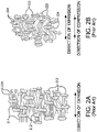
Figs. 2A and 2B are schematic representations of a microstructure of ePTFE material of the prior art; -
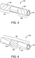
Fig. 3 is a perspective view of a length extensible implantable device in accordance with the present disclosure; -
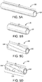
Fig. 4 is a perspective view of another length extensible implantable device in accordance with the present disclosure; and -
Figs. 5A - 5D are perspective views of a length extensible implantable device in various stages. - Like reference symbols in the various drawings indicate like elements.
- This disclosure describes devices, systems, and methods that are useful, for example, for repairing, supporting, and/or replacing anatomical lumens. Several implantable medical devices are described herein, and in general any of the features described with respect to a particular device may also be used with any of the other devices described herein. In some examples, one or more features described with respect to a particular device may be added to or included with another device. Also, various combinations or sub-combinations of any of the features described herein may generally be used with any of the devices described herein.
- In general, any of the implantable devices described herein can be delivered to, and deployed at, an in vivo deployment site within a body of a patient using variously minimally invasive surgical techniques. Likewise, these devices may also be surgically implanted via vascular surgical techniques.
- Further, any of the implantable medical devices described herein can be delivered to, and deployed at, an in vivo deployment site within a body of a patient using various minimally invasive transcatheter deployment techniques. For example, any of the implantable medical devices described herein may be releasably attached to a delivery catheter, and the device and delivery catheter may be loaded into a delivery sheath. The delivery sheath may be introduced to the vasculature of the patient and advanced through the vasculature, until a distal end of the delivery sheath is located at or near the target in vivo deployment site. The implantable medical device may be deployed at the deployment site, for example, by retracting the delivery sheath and/or advancing the delivery catheter and the implantable medical device and detaching the implantable medical device from the delivery catheter. The delivery catheter and delivery sheath can then be withdrawn or retracted from the body of the patient.
- Any of the implantable medical devices discussed herein can be used to repair, replace, and/or provide support to a body lumen. In various embodiments, implantable medical devices of the present disclosure can be used in a body lumen, including those within the circulatory and gastrointestinal systems.
- As used herein, "implantable" means implanted in the body of a patient for more than 29 days.
- As used herein, the term "constrain" means: (i) to limit extension, occurring either through self-expansion or assisted expansion, of the length of an implantable device; or (ii) to cover or surround, but not otherwise restrain, an implantable device such as for storage or biocompatibility reasons and/or to provide protection to the implantable device and/or the vasculature.
-
Figs. 1A-1C describe perspective views of various example length extensibleimplantable devices 100 comprising a poroustubular member 102 and a longitudinal constrainingmember 104. Length extensibleimplantable device 100 can be implanted in the body of a patient either alone or in combination with one or more other components. For example, length extensibleimplantable device 100 can be combined with a suitable stent, forming a stent-graft. Further, lengthextensible implant 100 can be combined with other grafts and/or stent-grafts. In other embodiments, the lengthextensible graft 100 may be provided with a stent (or stent graft) on only one end or alternatively on more than one end or even each end of the lengthextensible graft 100. A stent graft is considered to be a stent provided with a graft covering all or a portion of the inner or outer surfaces of the stent or both the inner and outer surfaces of the stent. Devices with more than two ends are also contemplated, such as bifurcated devices. Any combination of length extensibleimplantable device 100 with any suitable medical device is within the scope of the present disclosure. - In various embodiments, porous
tubular member 102 is a porous ePTFE member. It is also appreciated that these types of materials may be provided with coatings such as elastomeric coatings and coatings including therapeutic agents (e.g., heparin). Coatings may be provided as surface coatings or alternatively may partially or entirely impregnate the porous materials. - Porous
tubular member 102 can, for example, comprise an ePTFE construct. In various embodiments, poroustubular member 102 comprises a longitudinally extruded and longitudinally expanded ePTFE tube, such as the tubes described inU.S. Pat. Nos. 3,953,566 and4,187,390 . In other embodiments, polymerictubular member 102 comprises a wrapped ePTFE film tube. For example,member 102 can comprises a tube made from an ePTFE film that has been cigarette wrapped on the surface of a mandrel or, alternatively, has been helically wrapped on the surface of a mandrel. Such ePTFE films of this type can be made generally as taught byU.S. Pat. Nos. 3,953,566 and4,187,390 . Likewise, conventional longitudinally extruded and expanded ePTFE tubes may be usefully reinforced with an external wrap of ePTFE film, typically, a helical wrap. However, any suitable porous ePTFE tubular member is within the scope of the present disclosure. - In various embodiments, porous
tubular member 102 comprises an ePTFE tube having a multiplicity of fibrils which in turn can be connected to a multiplicity of nodes. The microstructure of poroustubular member 102 can comprise a multiplicity of fibrils having a mean fibril length. Mean fibril length can be determined, for example, by examining a photomicrograph of the surface of poroustubular member 102 and by taking the mean of ten measurements made in the predominant direction of the fibrils between nodes connected by fibrils. First, a photomicrograph is made of a representative region of the sample surface, of adequate magnification to show at least five sequential fibrils within the length of the photomicrograph. A series of five measurements are taken along a straight line drawn across the surface of the photomicrograph in the predominant direction of the fibrils followed by a second series of five measurements made along a second line drawn parallel to the first. A measurement constitutes the distance between adjacent nodes connected by at least one fibril. The ten measurements obtained by this method are meant to obtain the mean fibril length of the region. - For example, as illustrated in
Figs.. 2A and 2B , poroustubular member 102 can comprise a microstructure ofnodes fibrils - In various embodiments, in the longitudinally uncompressed configuration, porous
tubular member 102 can comprise a multiplicity of straight orunbent fibrils 214. Similarly, visual observation of a magnified longitudinal cross section of poroustubular member 102 indicates that a majority of the fibrils straight or unbent. - For example, after longitudinal compression,
portion 110 of poroustubular member 102 comprises a multiplicity ofbent fibrils 224. Similarly, visual observation of a magnified longitudinal cross section ofportion 110 can indicate that a majority of thefibrils 224 connected tonodes 222 are relatively straight or unbent. - In various embodiments, at least a portion of porous
tubular member 102 is held in a longitudinally compressed configuration by longitudinal constrainingmember 104. As illustrated inFigs. 1A-1C , in such configurations, longitudinal constrainingmember 104 can surround aportion 110 of an abluminal surface of poroustubular member 102 and maintainportion 110 in the longitudinally compressed configuration. In various embodiments,portion 110 is the entire length of poroustubular member 102. - In various embodiments,
portion 110 of poroustubular member 102, when compressed to the laterally compressed configuration, comprises a multiplicity of bent fibrils. In such embodiments, the mean fibril length inportion 110 is shorter than the mean fibril length of poroustubular member 102 in the initial, longitudinally uncompressed configuration. Further, visual observation of a magnified surface ofportion 110 can indicate that a majority of the fibrils are relatively non-parallel and bent in relation to the longitudinal axis of the tubular member. - Longitudinal constraining
member 104 is capable of rupturing when force
is applied in a particular direction. For example, in configurations in which aportion 110 of poroustubular member 102 is held in the longitudinal compressed configuration, applying tension to one or both ends of porous tubular member can cause longitudinal constrainingmember 104 to rupture. Rupture of longitudinal constrainingmember 104 can permitportion 110 to extend from the longitudinally compressed configuration to a less compressed configuration having fibrils that are less bent. - In other examples, longitudinal constraining
member 104 can be ruptured by applying a radial force. For example, a balloon can be used to apply radial force to poroustubular member 102, rupturing longitudinal constrainingmember 104 and permitting extension ofportion 110 to a lesser compressed configuration having fibrils that are less bent. - With reference to
Figs. 1A - 1C , in various embodiments, longitudinal constrainingmember 104 can comprise a variety of different tubular forms. For example, longitudinal constrainingmember 104 can comprise an ePTFE film. In various embodiments, longitudinal constrainingmember 104 comprises an ePTFE film having a multiplicity of nodes connected by fibrils, such as those taught byU.S. Pat. Nos. 3,953,566 ,4,187,390 , and5,814,405 . -
Fig. 1A illustrates a film wrapped around the surface of poroustubular member 102 at a low angle in relation to a longitudinal axis of the porous tubular member. For example, the film can be wrapped between about 0° and 45° relative to the longitudinal axis of poroustubular member 102. - In various embodiments, as illustrated in
Fig. 1B , longitudinal constrainingmember 104 can comprise a film wrapped around the surface of poroustubular member 102 at a higher angle in relation to the longitudinal axis of the porous tubular member. For example, the film can be wrapped between about 45° and 90° relative to the longitudinal axis of poroustubular member 102. - In yet other embodiments, longitudinal constraining
member 104 can comprise a tubular member capable of rupturing upon the application of a sufficiently large force. Such a tubular member can comprise a tubular wall having a multiplicity of slits, holes, and/or perforations that facilitate rupturing. As illustrated inFig. 1C , longitudinal constrainingmember 104 can comprise, for example, a perforated tube. - As illustrated in the perspective view of
Fig. 3 ,implantable device 100 can comprise a first longitudinal constrainingmember 104 and a second longitudinal constrainingmember 334. For example, first longitudinal constrainingmember 104 can surround afirst portion 110 of poroustubular member 102, and second longitudinal constrainingmember 334 can surround asecond portion 330 of poroustubular member 102. - In various embodiments,
first portion 110 andsecond portion 330 can comprise at least a part of the same portion, such that second longitudinal constrainingmember 334 surrounds first longitudinal constrainingmember 104. For example, the perspective view ofFig. 4 illustrates second longitudinal constrainingmember 334 surroundingsecond portion 330 and a part offirst portion 110. Any configuration of first and second longitudinal constraining members, including partial or complete overlap of the two constraining members, is within the scope of the present disclosure. Further, the use of any number of longitudinal constraining members is within the scope of the present disclosure. - First longitudinal constraining
member 104 and/or second longitudinal constrainingmember 334 can optionally be secured to poroustubular member 102, for example, to maintain the longitudinal constraining members in a desired orientation and position relative to poroustubular member 102. For example, first longitudinal constrainingmember 104 and/or second longitudinal constrainingmember 334 can be secured to poroustubular member 102 by applying an adhesive to a segment of an abluminal surface of poroustubular member 102 and/or the inner surface of the longitudinal constraining members. In various embodiments, a thermoplastic polymer adhesive, including a tetrafluoroethylene and perfluoromethyl vinyl ether copolymer, such as those described inU.S. Pat. No. 7,462,675 , can be used. In other embodiments, a fluoroelastomer adhesive, such as a FEP, can be used. Any means capable of securing first longitudinal constrainingmember 104 and/or second longitudinal constrainingmember 334 to firstporous tubular member 102 is within the scope of the present disclosure. - A method for making a length extensible implantable device of the present disclosure is described as follows. A porous tubular member in a longitudinally uncompressed configuration is obtained and fitted coaxially over a mandrel having an outside diameter the same as or slightly larger than the inside diameter of the porous tubular member. The tubular member is longitudinally compressed by a compressive force so that the length of the tube is reduced to a desired length. A longitudinal constraining member is placed over at least a portion of the porous tubular member to maintain the portion of the member in the longitudinally compressed configuration. The longitudinal constraining member can optionally be secured to the porous tubular member. The compressive force on the porous tubular member is released, and the longitudinally compressed porous tubular member is removed from the mandrel.
-
Figs. 5A - 5D illustrate a porous tubular member in various stages of a method for forming the porous tubular member into a length extensible implantable device. For example,Fig. 5A illustrates poroustubular member 102 in an initial, longitudinally uncompressed configuration. In the longitudinally uncompressed configuration, poroustubular member 102 can comprise a length f1. -
Fig. 5B illustrates poroustubular member 102 after a compressive force is applied. As the compressive force is applied, poroustubular member 102 is compressed from the initial, longitudinally uncompressed configuration to the longitudinally compressed configuration. In the longitudinally compressed configuration, poroustubular member 102 has a length ℓ2, which is shorter than f1. In various embodiments, poroustubular member 102 is biased such that, upon release of the compressive force, it will at extend from ℓ2 at least partially back to f1. - In various embodiments, ℓ2 can comprise a length that is between about 50% and 75% of ℓ1, such that compression from f1 to ℓ2 reduces the length of porous
tubular member 102 to between 50% and 75% of its uncompressed length. In other embodiments, f2 can comprise a length that is between about 25% and 50% of f1. In yet other embodiments, ℓ2 can comprise a length that is between about 5% and 25% of f1. Any relationship between ℓ2 and f1 is within the scope of the present disclosure. - After porous
tubular member 102 is compressed to a desired length ℓ2, at least one longitudinal constrainingmember 104 is applied around the abluminal surface of poroustubular member 102 to maintain at least aportion 110 of poroustubular member 102 in the longitudinally compressed configuration. For example,Fig. 5C illustrates poroustubular member 102 covered by longitudinal constrainingmember 104. In various embodiments, and as illustrated inFig. 5C ,portion 110 covered by longitudinal constrainingmember 104 can comprise the entire length (ℓ2) of poroustubular member 102. In other embodiments,portion 110 is less than the entire length of porous tubular members. - The longitudinal constraining
member 104 comprises a film. In such embodiments, the film is wrapped aroundportion 110 of poroustubular member 102 in the longitudinally compressed configuration. As previously discussed, the film can be wrapped at a relatively low (about 0° to 45°) or a relatively high (about 45° to 90°) wrap angle relative to a longitudinal axis of poroustubular member 102. The film can also be wrapped at multiple angles, such as
embodiments in which multiple layers of film are wrapped in multiple directions along the abluminal surface of poroustubular member 102. - Further disclosed is a longitudinal constraining
member 104 comprising a tubular element, such as a perforated tube. In such configurations, the tubular element is fitted along the surface ofportion 110 of poroustubular member 102 in the longitudinally compressed configuration. - Longitudinal constraining
member 104 can optionally be secured to poroustubular member 102. For example, an adhesive can be applied to the abluminal surface of poroustubular member 102. In other examples, an adhesive can be applied to the inner surface of longitudinal constrainingmember 104. However, as mentioned above, any manner of securing a longitudinal constraining member to a porous tubular member is within the scope of the present disclosure. - After
portion 110 of poroustubular member 102 has been secured in the longitudinally compressed configuration by at least one longitudinal constrainingmember 104, the compressive force used to shorten poroustubular member 102 from f1 to ℓ2 can be relieved while longitudinal constrainingmember 104 maintainsportion 110 in a compressed configuration, forming length extensibleimplantable device 100. Ifportion 110 comprises less than the entire length of poroustubular member 102, upon release of the compressive force, the segment of poroustubular member 102 not constrained can expand to its original length, leavingonly portion 110 in the longitudinally compressed configuration. In embodiments in which the entirety length of poroustubular member 102 is covered by longitudinal constraining member 104 (in other words, whereportion 110 is equal to ℓ2), all of poroustubular member 102 remains in the longitudinally compressed configuration. - In various embodiments, a second porous tubular member can be positioned around
portion 110,portion 330, and or all of poroustubular member 102. In such configurations, longitudinal constrainingmembers 104 and/or 334 are sandwiched between poroustubular member 102 and a second porous tubular member, such that longitudinal constrainingmembers 110 and/or 330 cannot be seen when visually examining the outer surface of length extensibleimplantable device 100. - After length extensible
implantable device 100 is formed, it can be adjusted and configured for use within the body of a patient. In various embodiments, as illustrated inFig. 5D , the length of length extensibleimplantable device 100 can be expanded to a length ℓ3, which is greater than ℓ2 and less than or equal to the length of poroustubular member 102 in the initial, laterally uncompressed configuration (having a length of ℓ1). In various embodiments, as force is applied to poroustubular member 102, longitudinal constrainingmember 104 can rupture or tear, forming one ormore ruptures 540. Once sufficient force is applied, poroustubular member 102 can continue expanding until it has expanded back to f1. - In various embodiments,
portion 110 of poroustubular member 102 can be extended from the longitudinally compressed configuration to a longer length (such as f3) by applying a force parallel to the longitudinal axis of poroustubular member 102. In other embodiments,portion 110 of poroustubular member 102 can be extended from the longitudinally compressed configuration to ℓ3 by applying a radial force toportion 110. - For example, a treatment provider can determine a desired length of length extensible
implantable device 100 before implanting the device into the vasculature of a patient. In other cases, the treatment provider can determine the desired length of length extensibleimplantable device 100 during the course of implanting the device into the vasculature and delivering the device to a treatment area of the patient. - Several characteristics and advantages have been set forth in the preceding description, including various alternatives together with details of the structure and function of the devices and methods. The disclosure is intended as illustrative only and as such is not intended to be exhaustive or limiting. It will be evident to those skilled in the art that various modifications may be made, especially in matters of structure, materials, elements, components, shapes, sizes, and arrangements of parts including combinations within the principles described herein, to the full extent indicated by the broad, general meaning of the terms in which the appended claims are expressed.
Claims (2)
- An implantable device (100) comprising:a porous ePTFE member (102) comprising a longitudinally compressed portion (110) including bent fibrils;a constraining member (104) covering at least a portion of the longitudinally compressed portion (110) thereby maintaining that portion in a longitudinally compressed configuration; andwherein upon application of a sufficient elongating force to the porous ePTFE tubular member (102), the constraining member ruptures and permits elongation of the compressed portion, wherein upon release of the elongating force, the elongated compressed portion recovers to a shorter length.
- A method for making an implantable device (100) comprising:longitudinally compressing a porous ePTFE tubular member (102) to a longitudinally compressed configuration, wherein a microstructure of the porous ePTFE tubular member (102)includes a multiplicity of fibrils, wherein a mean fibril length in the longitudinally compressed configuration is less than a mean fibril length prior to longitudinally compressing the porous member;wrapping a film around at least a portion of a length of an abluminal surface of the porous ePTFE tubular member (102) as a constraining member (104) when the porous ePTFE tubular member (102) is in the longitudinally compressed configuration thereby maintaining that portion in a longitudinally compressed configuration; and wherein upon application of a sufficient elongating force to the porous ePTFE tubular member (102), the constraining member ruptures and permits elongation of the compressed portion, wherein upon release of the elongating force, the elongated compressed portion recovers to a shorter length.
Applications Claiming Priority (4)
| Application Number | Priority Date | Filing Date | Title |
|---|---|---|---|
| US201361912414P | 2013-12-05 | 2013-12-05 | |
| US14/558,296 US10842918B2 (en) | 2013-12-05 | 2014-12-02 | Length extensible implantable device and methods for making such devices |
| PCT/US2014/068430 WO2015084995A1 (en) | 2013-12-05 | 2014-12-03 | Length extensible implantable device and methods for making such devices |
| EP14812860.6A EP3076899B1 (en) | 2013-12-05 | 2014-12-03 | Length extensible implantable device and methods for making such devices |
Related Parent Applications (2)
| Application Number | Title | Priority Date | Filing Date |
|---|---|---|---|
| EP14812860.6A Division EP3076899B1 (en) | 2013-12-05 | 2014-12-03 | Length extensible implantable device and methods for making such devices |
| EP14812860.6A Division-Into EP3076899B1 (en) | 2013-12-05 | 2014-12-03 | Length extensible implantable device and methods for making such devices |
Publications (2)
| Publication Number | Publication Date |
|---|---|
| EP3363409A1 EP3363409A1 (en) | 2018-08-22 |
| EP3363409B1 true EP3363409B1 (en) | 2022-05-04 |
Family
ID=53270079
Family Applications (2)
| Application Number | Title | Priority Date | Filing Date |
|---|---|---|---|
| EP14812860.6A Active EP3076899B1 (en) | 2013-12-05 | 2014-12-03 | Length extensible implantable device and methods for making such devices |
| EP18167101.7A Active EP3363409B1 (en) | 2013-12-05 | 2014-12-03 | Length extensible implantable device and methods for making such devices |
Family Applications Before (1)
| Application Number | Title | Priority Date | Filing Date |
|---|---|---|---|
| EP14812860.6A Active EP3076899B1 (en) | 2013-12-05 | 2014-12-03 | Length extensible implantable device and methods for making such devices |
Country Status (5)
| Country | Link |
|---|---|
| US (2) | US10842918B2 (en) |
| EP (2) | EP3076899B1 (en) |
| ES (1) | ES2924201T3 (en) |
| HK (1) | HK1258052A1 (en) |
| WO (1) | WO2015084995A1 (en) |
Families Citing this family (14)
| Publication number | Priority date | Publication date | Assignee | Title |
|---|---|---|---|---|
| US10166128B2 (en) | 2011-01-14 | 2019-01-01 | W. L. Gore & Associates. Inc. | Lattice |
| US9839540B2 (en) | 2011-01-14 | 2017-12-12 | W. L. Gore & Associates, Inc. | Stent |
| US9283072B2 (en) | 2012-07-25 | 2016-03-15 | W. L. Gore & Associates, Inc. | Everting transcatheter valve and methods |
| US9931193B2 (en) | 2012-11-13 | 2018-04-03 | W. L. Gore & Associates, Inc. | Elastic stent graft |
| US9101469B2 (en) | 2012-12-19 | 2015-08-11 | W. L. Gore & Associates, Inc. | Prosthetic heart valve with leaflet shelving |
| US9144492B2 (en) | 2012-12-19 | 2015-09-29 | W. L. Gore & Associates, Inc. | Truncated leaflet for prosthetic heart valves, preformed valve |
| US9968443B2 (en) | 2012-12-19 | 2018-05-15 | W. L. Gore & Associates, Inc. | Vertical coaptation zone in a planar portion of prosthetic heart valve leaflet |
| US10842918B2 (en) | 2013-12-05 | 2020-11-24 | W.L. Gore & Associates, Inc. | Length extensible implantable device and methods for making such devices |
| US9827094B2 (en) | 2014-09-15 | 2017-11-28 | W. L. Gore & Associates, Inc. | Prosthetic heart valve with retention elements |
| AU2016403450B2 (en) | 2016-04-21 | 2019-10-03 | W. L. Gore & Associates, Inc. | Diametrically adjustable endoprostheses and associated systems and methods |
| EP3687451B1 (en) | 2017-09-27 | 2023-12-13 | Edwards Lifesciences Corporation | Prosthetic valve with expandable frame |
| WO2019089136A1 (en) | 2017-10-31 | 2019-05-09 | W. L. Gore & Associates, Inc. | Medical valve and leaflet promoting tissue ingrowth |
| US11497601B2 (en) | 2019-03-01 | 2022-11-15 | W. L. Gore & Associates, Inc. | Telescoping prosthetic valve with retention element |
| CN112915255B (en) * | 2021-01-20 | 2021-12-03 | 浙江大学 | Multi-scale biological scaffold and manufacturing method and application thereof |
Family Cites Families (208)
| Publication number | Priority date | Publication date | Assignee | Title |
|---|---|---|---|---|
| SE392582B (en) | 1970-05-21 | 1977-04-04 | Gore & Ass | PROCEDURE FOR THE PREPARATION OF A POROST MATERIAL, BY EXPANDING AND STRETCHING A TETRAFLUORETENE POLYMER PREPARED IN AN PASTE-FORMING EXTENSION PROCEDURE |
| CA1147109A (en) | 1978-11-30 | 1983-05-31 | Hiroshi Mano | Porous structure of polytetrafluoroethylene and process for production thereof |
| US5071609A (en) | 1986-11-26 | 1991-12-10 | Baxter International Inc. | Process of manufacturing porous multi-expanded fluoropolymers |
| US4816339A (en) | 1987-04-28 | 1989-03-28 | Baxter International Inc. | Multi-layered poly(tetrafluoroethylene)/elastomer materials useful for in vivo implantation |
| US4877661A (en) | 1987-10-19 | 1989-10-31 | W. L. Gore & Associates, Inc. | Rapidly recoverable PTFE and process therefore |
| GB2211190A (en) | 1987-10-19 | 1989-06-28 | Gore & Ass | Rapid recoverable ptfe and a process for its manufacture |
| US5026513A (en) | 1987-10-19 | 1991-06-25 | W. L. Gore & Associates, Inc. | Process for making rapidly recoverable PTFE |
| US4955899A (en) | 1989-05-26 | 1990-09-11 | Impra, Inc. | Longitudinally compliant vascular graft |
| US5064435A (en) | 1990-06-28 | 1991-11-12 | Schneider (Usa) Inc. | Self-expanding prosthesis having stable axial length |
| US6128068A (en) | 1991-02-22 | 2000-10-03 | Canon Kabushiki Kaisha | Projection exposure apparatus including an illumination optical system that forms a secondary light source with a particular intensity distribution |
| US5342305A (en) | 1992-08-13 | 1994-08-30 | Cordis Corporation | Variable distention angioplasty balloon assembly |
| US5628782A (en) | 1992-12-11 | 1997-05-13 | W. L. Gore & Associates, Inc. | Method of making a prosthetic vascular graft |
| KR100295124B1 (en) | 1993-01-25 | 2001-09-17 | 이노우에 노리유끼 | Polytetrafluoroethylene porous membrane and preparation method thereof |
| US6027779A (en) | 1993-08-18 | 2000-02-22 | W. L. Gore & Associates, Inc. | Thin-wall polytetrafluoroethylene tube |
| CA2169549C (en) | 1993-08-18 | 2000-07-11 | James D. Lewis | A tubular intraluminal graft |
| AU8012394A (en) | 1993-10-01 | 1995-05-01 | Emory University | Self-expanding intraluminal composite prosthesis |
| US5549663A (en) | 1994-03-09 | 1996-08-27 | Cordis Corporation | Endoprosthesis having graft member and exposed welded end junctions, method and procedure |
| ES2216015T3 (en) | 1994-05-06 | 2004-10-16 | Bard Peripheral Vascular, Inc. | SET FOR THE TREATMENT OF A GLASS OF THE BODY. |
| EP0688545B1 (en) | 1994-06-17 | 2002-09-18 | Terumo Kabushiki Kaisha | Method for manufacturing an indwelling stent |
| EP0778753B1 (en) | 1994-09-02 | 1999-09-22 | W.L. Gore & Associates, Inc. | Method of making an asymmetrical porous ptfe form |
| CA2183350C (en) | 1994-09-02 | 1999-04-27 | Phillip A. Branca | Porous polytetrafluoroethylene compositions |
| CA2301351C (en) | 1994-11-28 | 2002-01-22 | Advanced Cardiovascular Systems, Inc. | Method and apparatus for direct laser cutting of metal stents |
| US6896696B2 (en) | 1998-11-20 | 2005-05-24 | Scimed Life Systems, Inc. | Flexible and expandable stent |
| US6451047B2 (en) | 1995-03-10 | 2002-09-17 | Impra, Inc. | Encapsulated intraluminal stent-graft and methods of making same |
| US5476589A (en) | 1995-03-10 | 1995-12-19 | W. L. Gore & Associates, Inc. | Porpous PTFE film and a manufacturing method therefor |
| US5534007A (en) | 1995-05-18 | 1996-07-09 | Scimed Life Systems, Inc. | Stent deployment catheter with collapsible sheath |
| US5766201A (en) | 1995-06-07 | 1998-06-16 | Boston Scientific Corporation | Expandable catheter |
| US5814405A (en) | 1995-08-04 | 1998-09-29 | W. L. Gore & Associates, Inc. | Strong, air permeable membranes of polytetrafluoroethylene |
| US20060271091A1 (en) | 1995-09-18 | 2006-11-30 | Campbell Carey V | Balloon catheter device |
| US5752934A (en) | 1995-09-18 | 1998-05-19 | W. L. Gore & Associates, Inc. | Balloon catheter device |
| US5868704A (en) | 1995-09-18 | 1999-02-09 | W. L. Gore & Associates, Inc. | Balloon catheter device |
| US5824037A (en) | 1995-10-03 | 1998-10-20 | Medtronic, Inc. | Modular intraluminal prostheses construction and methods |
| US6193745B1 (en) | 1995-10-03 | 2001-02-27 | Medtronic, Inc. | Modular intraluminal prosteheses construction and methods |
| US6689162B1 (en) | 1995-10-11 | 2004-02-10 | Boston Scientific Scimed, Inc. | Braided composite prosthesis |
| US5788626A (en) | 1995-11-21 | 1998-08-04 | Schneider (Usa) Inc | Method of making a stent-graft covered with expanded polytetrafluoroethylene |
| US6042605A (en) | 1995-12-14 | 2000-03-28 | Gore Enterprose Holdings, Inc. | Kink resistant stent-graft |
| US5843158A (en) | 1996-01-05 | 1998-12-01 | Medtronic, Inc. | Limited expansion endoluminal prostheses and methods for their use |
| US5747128A (en) | 1996-01-29 | 1998-05-05 | W. L. Gore & Associates, Inc. | Radially supported polytetrafluoroethylene vascular graft |
| JPH09241412A (en) | 1996-03-07 | 1997-09-16 | Sumitomo Electric Ind Ltd | Drawn polytetrafluoroethylene tube and its production |
| US5843161A (en) | 1996-06-26 | 1998-12-01 | Cordis Corporation | Endoprosthesis assembly for percutaneous deployment and method of deploying same |
| US5769884A (en) | 1996-06-27 | 1998-06-23 | Cordis Corporation | Controlled porosity endovascular implant |
| US5749852A (en) | 1996-07-23 | 1998-05-12 | Medtronic, Inc. | Sheath system for autoperfusion dilatation catheter balloon |
| US6174329B1 (en) | 1996-08-22 | 2001-01-16 | Advanced Cardiovascular Systems, Inc. | Protective coating for a stent with intermediate radiopaque coating |
| US6261320B1 (en) | 1996-11-21 | 2001-07-17 | Radiance Medical Systems, Inc. | Radioactive vascular liner |
| US6010529A (en) | 1996-12-03 | 2000-01-04 | Atrium Medical Corporation | Expandable shielded vessel support |
| US6315791B1 (en) | 1996-12-03 | 2001-11-13 | Atrium Medical Corporation | Self-expanding prothesis |
| US5925061A (en) | 1997-01-13 | 1999-07-20 | Gore Enterprise Holdings, Inc. | Low profile vascular stent |
| US5957974A (en) | 1997-01-23 | 1999-09-28 | Schneider (Usa) Inc | Stent graft with braided polymeric sleeve |
| US5853419A (en) | 1997-03-17 | 1998-12-29 | Surface Genesis, Inc. | Stent |
| CA2235911C (en) | 1997-05-27 | 2003-07-29 | Schneider (Usa) Inc. | Stent and stent-graft for treating branched vessels |
| US6203536B1 (en) | 1997-06-17 | 2001-03-20 | Medtronic, Inc. | Medical device for delivering a therapeutic substance and method therefor |
| US6500174B1 (en) | 1997-07-08 | 2002-12-31 | Atrionix, Inc. | Circumferential ablation device assembly and methods of use and manufacture providing an ablative circumferential band along an expandable member |
| US6042606A (en) | 1997-09-29 | 2000-03-28 | Cook Incorporated | Radially expandable non-axially contracting surgical stent |
| US6161399A (en) | 1997-10-24 | 2000-12-19 | Iowa-India Investments Company Limited | Process for manufacturing a wire reinforced monolayer fabric stent |
| US5931865A (en) | 1997-11-24 | 1999-08-03 | Gore Enterprise Holdings, Inc. | Multiple-layered leak resistant tube |
| US6626939B1 (en) | 1997-12-18 | 2003-09-30 | Boston Scientific Scimed, Inc. | Stent-graft with bioabsorbable structural support |
| US6190406B1 (en) | 1998-01-09 | 2001-02-20 | Nitinal Development Corporation | Intravascular stent having tapered struts |
| US6488701B1 (en) | 1998-03-31 | 2002-12-03 | Medtronic Ave, Inc. | Stent-graft assembly with thin-walled graft component and method of manufacture |
| US6042588A (en) | 1998-03-03 | 2000-03-28 | Scimed Life Systems, Inc | Stent delivery system |
| US5935162A (en) | 1998-03-16 | 1999-08-10 | Medtronic, Inc. | Wire-tubular hybrid stent |
| JP4222655B2 (en) | 1998-04-06 | 2009-02-12 | ジャパンゴアテックス株式会社 | Medical tube |
| US6217609B1 (en) | 1998-06-30 | 2001-04-17 | Schneider (Usa) Inc | Implantable endoprosthesis with patterned terminated ends and methods for making same |
| US6156064A (en) | 1998-08-14 | 2000-12-05 | Schneider (Usa) Inc | Stent-graft-membrane and method of making the same |
| US6755856B2 (en) | 1998-09-05 | 2004-06-29 | Abbott Laboratories Vascular Enterprises Limited | Methods and apparatus for stenting comprising enhanced embolic protection, coupled with improved protection against restenosis and thrombus formation |
| US7815763B2 (en) | 2001-09-28 | 2010-10-19 | Abbott Laboratories Vascular Enterprises Limited | Porous membranes for medical implants and methods of manufacture |
| NO984143L (en) | 1998-09-09 | 2000-03-10 | Norsk Hydro As | New process for producing surface modifying substances |
| US6336937B1 (en) | 1998-12-09 | 2002-01-08 | Gore Enterprise Holdings, Inc. | Multi-stage expandable stent-graft |
| US6350277B1 (en) | 1999-01-15 | 2002-02-26 | Scimed Life Systems, Inc. | Stents with temporary retaining bands |
| US7049380B1 (en) | 1999-01-19 | 2006-05-23 | Gore Enterprise Holdings, Inc. | Thermoplastic copolymer of tetrafluoroethylene and perfluoromethyl vinyl ether and medical devices employing the copolymer |
| WO2000042947A2 (en) * | 1999-01-22 | 2000-07-27 | Gore Enterprise Holdings, Inc. | Covered endoprosthesis and delivery system |
| US6673102B1 (en) * | 1999-01-22 | 2004-01-06 | Gore Enterprises Holdings, Inc. | Covered endoprosthesis and delivery system |
| AU3289999A (en) | 1999-02-10 | 2000-08-29 | Gore Enterprise Holdings, Inc. | Multiple-layered leak-resistant tube |
| US6245012B1 (en) | 1999-03-19 | 2001-06-12 | Nmt Medical, Inc. | Free standing filter |
| GB2352205A (en) | 1999-06-28 | 2001-01-24 | Nestle Sa | Chilled roller for moulding a food product |
| US6890350B1 (en) | 1999-07-28 | 2005-05-10 | Scimed Life Systems, Inc. | Combination self-expandable, balloon-expandable endoluminal device |
| US6673107B1 (en) | 1999-12-06 | 2004-01-06 | Advanced Cardiovascular Systems, Inc. | Bifurcated stent and method of making |
| US6740962B1 (en) | 2000-02-24 | 2004-05-25 | Micron Technology, Inc. | Tape stiffener, semiconductor device component assemblies including same, and stereolithographic methods for fabricating same |
| US6756094B1 (en) | 2000-02-28 | 2004-06-29 | Scimed Life Systems, Inc. | Balloon structure with PTFE component |
| US6379382B1 (en) | 2000-03-13 | 2002-04-30 | Jun Yang | Stent having cover with drug delivery capability |
| US6436132B1 (en) | 2000-03-30 | 2002-08-20 | Advanced Cardiovascular Systems, Inc. | Composite intraluminal prostheses |
| US6352552B1 (en) | 2000-05-02 | 2002-03-05 | Scion Cardio-Vascular, Inc. | Stent |
| US7419678B2 (en) | 2000-05-12 | 2008-09-02 | Cordis Corporation | Coated medical devices for the prevention and treatment of vascular disease |
| US8252044B1 (en) | 2000-11-17 | 2012-08-28 | Advanced Bio Prosthestic Surfaces, Ltd. | Device for in vivo delivery of bioactive agents and method of manufacture thereof |
| US6554841B1 (en) | 2000-09-22 | 2003-04-29 | Scimed Life Systems, Inc. | Striped sleeve for stent delivery |
| US8690910B2 (en) | 2000-12-07 | 2014-04-08 | Integrated Vascular Systems, Inc. | Closure device and methods for making and using them |
| DE10061936A1 (en) | 2000-12-13 | 2002-07-04 | Valentin Kramer | Object from ePTFE and method of manufacturing the same |
| US7083642B2 (en) | 2000-12-22 | 2006-08-01 | Avantec Vascular Corporation | Delivery of therapeutic capable agents |
| US20020161388A1 (en) | 2001-02-27 | 2002-10-31 | Samuels Sam L. | Elastomeric balloon support fabric |
| US6716239B2 (en) | 2001-07-03 | 2004-04-06 | Scimed Life Systems, Inc. | ePTFE graft with axial elongation properties |
| EP1414369A2 (en) | 2001-07-27 | 2004-05-06 | Medtronic, Inc. | Adventitial fabric reinforced porous prosthetic graft |
| US7288105B2 (en) | 2001-08-01 | 2007-10-30 | Ev3 Endovascular, Inc. | Tissue opening occluder |
| US20030045923A1 (en) | 2001-08-31 | 2003-03-06 | Mehran Bashiri | Hybrid balloon expandable/self expanding stent |
| US6827737B2 (en) | 2001-09-25 | 2004-12-07 | Scimed Life Systems, Inc. | EPTFE covering for endovascular prostheses and method of manufacture |
| AU2002337598A1 (en) | 2001-10-04 | 2003-04-14 | Neovasc Medical Ltd. | Flow reducing implant |
| US6541589B1 (en) | 2001-10-15 | 2003-04-01 | Gore Enterprise Holdings, Inc. | Tetrafluoroethylene copolymer |
| US6946173B2 (en) | 2002-03-21 | 2005-09-20 | Advanced Cardiovascular Systems, Inc. | Catheter balloon formed of ePTFE and a diene polymer |
| WO2003082076A2 (en) | 2002-03-25 | 2003-10-09 | Nmt Medical, Inc. | Patent foramen ovale (pfo) closure clips |
| US7789908B2 (en) | 2002-06-25 | 2010-09-07 | Boston Scientific Scimed, Inc. | Elastomerically impregnated ePTFE to enhance stretch and recovery properties for vascular grafts and coverings |
| US20040024448A1 (en) | 2002-08-05 | 2004-02-05 | Chang James W. | Thermoplastic fluoropolymer-coated medical devices |
| CN1678366B (en) | 2002-08-23 | 2010-06-09 | 国立循环器病中心总长所代表的日本国 | Stent and process for producing the same |
| US7273492B2 (en) | 2002-08-27 | 2007-09-25 | Advanced Cardiovascular Systems Inc. | Stent for treating vulnerable plaque |
| US6878162B2 (en) | 2002-08-30 | 2005-04-12 | Edwards Lifesciences Ag | Helical stent having improved flexibility and expandability |
| CA2499961C (en) | 2002-09-26 | 2014-12-30 | Advanced Bio Prosthetic Surfaces, Ltd. | High strength vacuum deposited nitinol alloy films, medical thin film graft materials and method of making same |
| US8282678B2 (en) | 2002-11-13 | 2012-10-09 | Allium Medical Solutions Ltd. | Endoluminal lining |
| US7001425B2 (en) | 2002-11-15 | 2006-02-21 | Scimed Life Systems, Inc. | Braided stent method for its manufacture |
| US7105018B1 (en) | 2002-12-30 | 2006-09-12 | Advanced Cardiovascular Systems, Inc. | Drug-eluting stent cover and method of use |
| US9125733B2 (en) | 2003-01-14 | 2015-09-08 | The Cleveland Clinic Foundation | Branched vessel endoluminal device |
| US20070207816A1 (en) | 2003-02-24 | 2007-09-06 | Polaris Wireless, Inc. | Location Estimation of Wireless Terminals Based on Combinations of Signal-Strength Measurements and Geometry-of-Arrival Measurements |
| US7011646B2 (en) | 2003-06-24 | 2006-03-14 | Advanced Cardiovascular Systems, Inc. | Balloon catheter having a balloon with a thickened wall portion |
| US7967829B2 (en) | 2003-10-09 | 2011-06-28 | Boston Scientific Scimed, Inc. | Medical device delivery system |
| US7763011B2 (en) | 2003-12-22 | 2010-07-27 | Boston Scientific Scimed, Inc. | Variable density braid stent |
| EP1725187A1 (en) | 2004-03-02 | 2006-11-29 | Boston Scientific Scimed, Inc. | Medical devices including metallic films and methods for making same |
| US20050273149A1 (en) | 2004-06-08 | 2005-12-08 | Tran Thomas T | Bifurcated stent delivery system |
| US7794490B2 (en) | 2004-06-22 | 2010-09-14 | Boston Scientific Scimed, Inc. | Implantable medical devices with antimicrobial and biodegradable matrices |
| US20060009835A1 (en) | 2004-07-07 | 2006-01-12 | Osborne Thomas A | Graft, stent graft and method |
| US8308789B2 (en) | 2004-07-16 | 2012-11-13 | W. L. Gore & Associates, Inc. | Deployment system for intraluminal devices |
| US8029563B2 (en) * | 2004-11-29 | 2011-10-04 | Gore Enterprise Holdings, Inc. | Implantable devices with reduced needle puncture site leakage |
| US8262720B2 (en) | 2004-12-02 | 2012-09-11 | Nitinol Development Corporation | Prosthesis comprising dual tapered stent |
| US20060135985A1 (en) | 2004-12-21 | 2006-06-22 | Cox Daniel L | Vulnerable plaque modification methods and apparatuses |
| US20060161241A1 (en) | 2005-01-14 | 2006-07-20 | Denise Barbut | Methods and devices for treating aortic atheroma |
| US20060190070A1 (en) * | 2005-02-23 | 2006-08-24 | Dieck Martin S | Rail stent and methods of use |
| US20060276883A1 (en) | 2005-06-01 | 2006-12-07 | Cook Incorporated | Tapered and distally stented elephant trunk stent graft |
| US7531611B2 (en) | 2005-07-05 | 2009-05-12 | Gore Enterprise Holdings, Inc. | Copolymers of tetrafluoroethylene |
| US7306729B2 (en) | 2005-07-18 | 2007-12-11 | Gore Enterprise Holdings, Inc. | Porous PTFE materials and articles produced therefrom |
| EP2179709B1 (en) | 2005-08-17 | 2011-10-05 | C. R. Bard, Inc. | Variable speed stent delivery system |
| US8956400B2 (en) | 2005-10-14 | 2015-02-17 | Flexible Stenting Solutions, Inc. | Helical stent |
| EP1933778B1 (en) | 2005-10-14 | 2010-01-06 | Gore Enterprise Holdings, Inc. | Device for deploying an implantable medical device |
| US7862607B2 (en) | 2005-12-30 | 2011-01-04 | C. R. Bard, Inc. | Stent with bio-resorbable connector and methods |
| US8778008B2 (en) | 2006-01-13 | 2014-07-15 | Aga Medical Corporation | Intravascular deliverable stent for reinforcement of vascular abnormalities |
| WO2007083288A2 (en) | 2006-01-23 | 2007-07-26 | Atria Medical Inc. | Heart anchor device |
| DE602006010171D1 (en) | 2006-02-24 | 2009-12-17 | Nat Univ Ireland | Minimally invasive intravascular treatment device |
| CA2643720A1 (en) | 2006-02-28 | 2007-09-07 | Debra A. Bebb | Flexible stretch stent-graft |
| US8025693B2 (en) | 2006-03-01 | 2011-09-27 | Boston Scientific Scimed, Inc. | Stent-graft having flexible geometries and methods of producing the same |
| US8585753B2 (en) | 2006-03-04 | 2013-11-19 | John James Scanlon | Fibrillated biodegradable prosthesis |
| US8425584B2 (en) | 2006-04-21 | 2013-04-23 | W. L. Gore & Associates, Inc. | Expandable covered stent with wide range of wrinkle-free deployed diameters |
| US8721704B2 (en) | 2006-04-21 | 2014-05-13 | W. L. Gore & Associates, Inc. | Expandable stent with wrinkle-free elastomeric cover |
| US20070254012A1 (en) | 2006-04-28 | 2007-11-01 | Ludwig Florian N | Controlled degradation and drug release in stents |
| US9114194B2 (en) | 2006-05-12 | 2015-08-25 | W. L. Gore & Associates, Inc. | Immobilized biologically active entities having high biological activity following mechanical manipulation |
| US20080140173A1 (en) | 2006-08-07 | 2008-06-12 | Sherif Eskaros | Non-shortening wrapped balloon |
| US7785290B2 (en) | 2006-08-07 | 2010-08-31 | Gore Enterprise Holdings, Inc. | Non-shortening high angle wrapped balloons |
| US8882826B2 (en) | 2006-08-22 | 2014-11-11 | Abbott Cardiovascular Systems Inc. | Intravascular stent |
| US8500793B2 (en) | 2006-09-07 | 2013-08-06 | C. R. Bard, Inc. | Helical implant having different ends |
| CA2663573C (en) | 2006-09-21 | 2015-04-07 | Cleveny Technologies | A specially configured and surface modified medical device with certain design features that utilize the intrinsic properties of tungsten, zirconium, tantalum and/or niobium |
| US20080097401A1 (en) | 2006-09-22 | 2008-04-24 | Trapp Benjamin M | Cerebral vasculature device |
| US20080097583A1 (en) | 2006-10-18 | 2008-04-24 | Conor Medsystems, Inc. | Stent with flexible hinges |
| US20080097582A1 (en) | 2006-10-18 | 2008-04-24 | Conor Medsystems, Inc. | Stent with flexible hinges |
| US9622888B2 (en) | 2006-11-16 | 2017-04-18 | W. L. Gore & Associates, Inc. | Stent having flexibly connected adjacent stent elements |
| JP5313928B2 (en) | 2007-02-05 | 2013-10-09 | ボストン サイエンティフィック リミテッド | Percutaneous valves and systems |
| BRPI0807260A2 (en) | 2007-02-09 | 2014-06-10 | Taheri Laduca Llc | "IMPLANTABLE STENT AND METHOD OF MANUFACTURING A TUBULAR GRAFT" |
| US8057531B2 (en) | 2007-06-29 | 2011-11-15 | Abbott Cardiovascular Systems Inc. | Stent having circumferentially deformable struts |
| US20100094405A1 (en) | 2008-10-10 | 2010-04-15 | Orbusneich Medical, Inc. | Bioabsorbable Polymeric Medical Device |
| US7988723B2 (en) | 2007-08-02 | 2011-08-02 | Flexible Stenting Solutions, Inc. | Flexible stent |
| US8679519B2 (en) | 2007-10-23 | 2014-03-25 | Abbott Cardiovascular Systems Inc. | Coating designs for the tailored release of dual drugs from polymeric coatings |
| US8317857B2 (en) | 2008-01-10 | 2012-11-27 | Telesis Research, Llc | Biodegradable self-expanding prosthesis |
| US8926688B2 (en) | 2008-01-11 | 2015-01-06 | W. L. Gore & Assoc. Inc. | Stent having adjacent elements connected by flexible webs |
| JP2011510796A (en) | 2008-02-05 | 2011-04-07 | シルク・ロード・メディカル・インコーポレイテッド | Intervention catheter system and method |
| US20090264989A1 (en) | 2008-02-28 | 2009-10-22 | Philipp Bonhoeffer | Prosthetic heart valve systems |
| EP2106820A1 (en) | 2008-03-31 | 2009-10-07 | Torsten Heilmann | Expansible biocompatible coats comprising a biologically active substance |
| US11484322B2 (en) * | 2018-01-03 | 2022-11-01 | Aneuclose Llc | Aneurysm neck bridge with a closeable opening or lumen through which embolic material is inserted into the aneurysm sac |
| EP2145917B1 (en) | 2008-07-17 | 2012-06-06 | W.L. Gore & Associates GmbH | Polymer coating comprising a complex of an ionic fluoropolyether and a counter ionic agent |
| JP2012501803A (en) | 2008-09-10 | 2012-01-26 | イーブイ3 インコーポレイテッド | Stents and catheters with improved stent deployment |
| US9149376B2 (en) | 2008-10-06 | 2015-10-06 | Cordis Corporation | Reconstrainable stent delivery system |
| US8470013B2 (en) | 2008-10-20 | 2013-06-25 | Imds Corporation | Systems and methods for aneurysm treatment and vessel occlusion |
| US7968190B2 (en) | 2008-12-19 | 2011-06-28 | Gore Enterprise Holdings, Inc. | PTFE fabric articles and method of making same |
| US8764813B2 (en) | 2008-12-23 | 2014-07-01 | Cook Medical Technologies Llc | Gradually self-expanding stent |
| US8353956B2 (en) * | 2009-02-17 | 2013-01-15 | Valtech Cardio, Ltd. | Actively-engageable movement-restriction mechanism for use with an annuloplasty structure |
| US8888836B2 (en) | 2009-04-07 | 2014-11-18 | Medtronic Vascular, Inc. | Implantable temporary flow restrictor device |
| JP2012524641A (en) | 2009-04-24 | 2012-10-18 | フレキシブル ステンティング ソリューションズ,インク. | Flexible device |
| EP2429453B1 (en) | 2009-05-14 | 2021-01-27 | Orbusneich Medical Pte. Ltd | Self-expanding stent with polygon transition zone |
| CA3009244C (en) | 2009-06-23 | 2020-04-28 | Endospan Ltd. | Vascular prostheses for treating aneurysms |
| AU2010263224B2 (en) | 2009-06-26 | 2014-02-06 | Cook Medical Technologies Llc | Linear clamps for anastomosis |
| US9327060B2 (en) | 2009-07-09 | 2016-05-03 | CARDINAL HEALTH SWITZERLAND 515 GmbH | Rapamycin reservoir eluting stent |
| US8936634B2 (en) | 2009-07-15 | 2015-01-20 | W. L. Gore & Associates, Inc. | Self constraining radially expandable medical devices |
| US8435282B2 (en) | 2009-07-15 | 2013-05-07 | W. L. Gore & Associates, Inc. | Tube with reverse necking properties |
| US8474120B2 (en) | 2009-10-09 | 2013-07-02 | W. L. Gore & Associates, Inc. | Bifurcated highly conformable medical device branch access |
| AU2010315651B2 (en) | 2009-11-03 | 2014-08-07 | Cook Medical Technologies Llc | Planar clamps for anastomosis |
| US20130204355A1 (en) | 2010-02-12 | 2013-08-08 | Spire Biomedical | Medical device made of eptfe partially coated with an antimicrobial material |
| CN101926699A (en) | 2010-07-13 | 2010-12-29 | 北京迈迪顶峰医疗科技有限公司 | Atrial septal pore-forming scaffold and conveyor thereof |
| US20130297002A1 (en) | 2010-07-20 | 2013-11-07 | Kyoto Medical Planning Co., Ltd. | Stent apparatus |
| CN201744060U (en) | 2010-08-17 | 2011-02-16 | 天健医疗科技(苏州)有限公司 | Step-type artery balloon expansion conduit |
| US20130297003A1 (en) | 2011-01-13 | 2013-11-07 | Innovia Llc | Endoluminal Drug Applicator and Method of Treating Diseased Vessels of the Body |
| US10166128B2 (en) | 2011-01-14 | 2019-01-01 | W. L. Gore & Associates. Inc. | Lattice |
| US9839540B2 (en) | 2011-01-14 | 2017-12-12 | W. L. Gore & Associates, Inc. | Stent |
| AU2012207362B2 (en) | 2011-01-18 | 2016-07-14 | Loma Vista Medical, Inc. | Inflatable medical devices |
| US9744033B2 (en) | 2011-04-01 | 2017-08-29 | W.L. Gore & Associates, Inc. | Elastomeric leaflet for prosthetic heart valves |
| JP2014516695A (en) | 2011-05-18 | 2014-07-17 | バトリックス・メディカル・インコーポレイテッド | Coated balloon for vascular stabilization |
| US10016579B2 (en) | 2011-06-23 | 2018-07-10 | W.L. Gore & Associates, Inc. | Controllable inflation profile balloon cover apparatus |
| CN106420107B (en) | 2011-11-16 | 2019-02-05 | 波顿医疗公司 | The device and method of reparation for aortic branch blood vessel |
| US9510935B2 (en) | 2012-01-16 | 2016-12-06 | W. L. Gore & Associates, Inc. | Articles including expanded polytetrafluoroethylene membranes with serpentine fibrils and having a discontinuous fluoropolymer layer thereon |
| CA2860530C (en) | 2012-01-16 | 2017-02-21 | W.L. Gore & Associates, Inc. | Articles including expanded polytetrafluoroethylene membranes with serpentine fibrils and having a discontinuous fluoropolymer layer thereon |
| US20130183515A1 (en) | 2012-01-16 | 2013-07-18 | Charles F. White | Articles including expanded polytetrafluoroethylene membranes with serpentine fibrils |
| EP2825129B2 (en) | 2012-03-16 | 2020-02-19 | Terumo Corporation | Stent and stent delivery device |
| US9114001B2 (en) * | 2012-10-30 | 2015-08-25 | Covidien Lp | Systems for attaining a predetermined porosity of a vascular device |
| US9931193B2 (en) | 2012-11-13 | 2018-04-03 | W. L. Gore & Associates, Inc. | Elastic stent graft |
| EP2931273A1 (en) | 2012-12-12 | 2015-10-21 | The Charlotte-Mecklenburg Hospital Authority D/B/A Carolinas Healthcare System | Methods of treating portal hypertension |
| US10279084B2 (en) | 2012-12-19 | 2019-05-07 | W. L. Gore & Associates, Inc. | Medical balloon devices and methods |
| US9855160B2 (en) | 2013-03-14 | 2018-01-02 | W. L. Gore & Associates, Inc. | Endoprosthesis delivery systems with deployment aids |
| US10905539B2 (en) | 2013-03-15 | 2021-02-02 | W. L. Gore & Associates, Inc. | Self-expanding, balloon expandable stent-grafts |
| CN108814768B (en) | 2013-07-22 | 2020-08-07 | 阿特利姆医疗公司 | Implants having expandable regions and methods of making and using the same |
| US10842918B2 (en) | 2013-12-05 | 2020-11-24 | W.L. Gore & Associates, Inc. | Length extensible implantable device and methods for making such devices |
| CN116172611A (en) | 2014-07-15 | 2023-05-30 | 皇家飞利浦有限公司 | Intrahepatic bypass apparatus and method |
| JP6470150B2 (en) | 2015-09-03 | 2019-02-13 | 日本ライフライン株式会社 | Stents and medical devices |
| US9789294B2 (en) | 2015-10-07 | 2017-10-17 | Edwards Lifesciences Corporation | Expandable cardiac shunt |
| US10004617B2 (en) | 2015-10-20 | 2018-06-26 | Cook Medical Technologies Llc | Woven stent device and manufacturing method |
| AU2016403450B2 (en) | 2016-04-21 | 2019-10-03 | W. L. Gore & Associates, Inc. | Diametrically adjustable endoprostheses and associated systems and methods |
| CA3078496C (en) | 2017-10-09 | 2023-02-28 | W. L. Gore & Associates, Inc. | Matched stent cover |
| US20200179663A1 (en) | 2018-12-11 | 2020-06-11 | W. L. Gore & Associates, Inc. | Medical devices for shunts, occluders, fenestrations and related systems and methods |
| JP7436007B2 (en) | 2020-02-04 | 2024-02-21 | 豊丸産業株式会社 | gaming machine |
-
2014
- 2014-12-02 US US14/558,296 patent/US10842918B2/en active Active
- 2014-12-03 EP EP14812860.6A patent/EP3076899B1/en active Active
- 2014-12-03 WO PCT/US2014/068430 patent/WO2015084995A1/en active Application Filing
- 2014-12-03 ES ES18167101T patent/ES2924201T3/en active Active
- 2014-12-03 EP EP18167101.7A patent/EP3363409B1/en active Active
-
2019
- 2019-01-11 HK HK19100429.0A patent/HK1258052A1/en unknown
-
2020
- 2020-11-20 US US16/953,662 patent/US11911537B2/en active Active
Also Published As
| Publication number | Publication date |
|---|---|
| US20150157770A1 (en) | 2015-06-11 |
| EP3363409A1 (en) | 2018-08-22 |
| EP3076899B1 (en) | 2018-05-16 |
| ES2924201T3 (en) | 2022-10-05 |
| EP3076899A1 (en) | 2016-10-12 |
| US20210138121A1 (en) | 2021-05-13 |
| US11911537B2 (en) | 2024-02-27 |
| HK1258052A1 (en) | 2019-11-01 |
| US10842918B2 (en) | 2020-11-24 |
| WO2015084995A1 (en) | 2015-06-11 |
Similar Documents
| Publication | Publication Date | Title |
|---|---|---|
| EP3363409B1 (en) | Length extensible implantable device and methods for making such devices | |
| US10682222B2 (en) | Modular vascular graft for low profile percutaneous delivery | |
| US11065097B2 (en) | Advanced kink-resistant stent graft | |
| US20220151761A1 (en) | Tapered implantable device and methods for making such devices | |
| US20170065400A1 (en) | Lattice | |
| US11918498B2 (en) | Internal iliac preservation devices and methods | |
| JP2010540190A5 (en) | ||
| JP2002531219A (en) | Multi-stage expandable stent / graft | |
| CN105025848A (en) | Endoprosthesis delivery systems with deployment aids |
Legal Events
| Date | Code | Title | Description |
|---|---|---|---|
| PUAI | Public reference made under article 153(3) epc to a published international application that has entered the european phase |
Free format text: ORIGINAL CODE: 0009012 |
|
| STAA | Information on the status of an ep patent application or granted ep patent |
Free format text: STATUS: REQUEST FOR EXAMINATION WAS MADE |
|
| 17P | Request for examination filed |
Effective date: 20180412 |
|
| AC | Divisional application: reference to earlier application |
Ref document number: 3076899 Country of ref document: EP Kind code of ref document: P |
|
| AK | Designated contracting states |
Kind code of ref document: A1 Designated state(s): AL AT BE BG CH CY CZ DE DK EE ES FI FR GB GR HR HU IE IS IT LI LT LU LV MC MK MT NL NO PL PT RO RS SE SI SK SM TR |
|
| STAA | Information on the status of an ep patent application or granted ep patent |
Free format text: STATUS: EXAMINATION IS IN PROGRESS |
|
| 17Q | First examination report despatched |
Effective date: 20190918 |
|
| REG | Reference to a national code |
Ref country code: HK Ref legal event code: DE Ref document number: 1258052 Country of ref document: HK |
|
| STAA | Information on the status of an ep patent application or granted ep patent |
Free format text: STATUS: EXAMINATION IS IN PROGRESS |
|
| GRAP | Despatch of communication of intention to grant a patent |
Free format text: ORIGINAL CODE: EPIDOSNIGR1 |
|
| STAA | Information on the status of an ep patent application or granted ep patent |
Free format text: STATUS: GRANT OF PATENT IS INTENDED |
|
| INTG | Intention to grant announced |
Effective date: 20211126 |
|
| GRAS | Grant fee paid |
Free format text: ORIGINAL CODE: EPIDOSNIGR3 |
|
| GRAA | (expected) grant |
Free format text: ORIGINAL CODE: 0009210 |
|
| STAA | Information on the status of an ep patent application or granted ep patent |
Free format text: STATUS: THE PATENT HAS BEEN GRANTED |
|
| AC | Divisional application: reference to earlier application |
Ref document number: 3076899 Country of ref document: EP Kind code of ref document: P |
|
| AK | Designated contracting states |
Kind code of ref document: B1 Designated state(s): AL AT BE BG CH CY CZ DE DK EE ES FI FR GB GR HR HU IE IS IT LI LT LU LV MC MK MT NL NO PL PT RO RS SE SI SK SM TR |
|
| REG | Reference to a national code |
Ref country code: GB Ref legal event code: FG4D |
|
| REG | Reference to a national code |
Ref country code: CH Ref legal event code: EP |
|
| REG | Reference to a national code |
Ref country code: AT Ref legal event code: REF Ref document number: 1488225 Country of ref document: AT Kind code of ref document: T Effective date: 20220515 |
|
| REG | Reference to a national code |
Ref country code: DE Ref legal event code: R096 Ref document number: 602014083635 Country of ref document: DE |
|
| REG | Reference to a national code |
Ref country code: IE Ref legal event code: FG4D |
|
| REG | Reference to a national code |
Ref country code: LT Ref legal event code: MG9D |
|
| REG | Reference to a national code |
Ref country code: NL Ref legal event code: MP Effective date: 20220504 |
|
| REG | Reference to a national code |
Ref country code: ES Ref legal event code: FG2A Ref document number: 2924201 Country of ref document: ES Kind code of ref document: T3 Effective date: 20221005 |
|
| REG | Reference to a national code |
Ref country code: AT Ref legal event code: MK05 Ref document number: 1488225 Country of ref document: AT Kind code of ref document: T Effective date: 20220504 |
|
| PG25 | Lapsed in a contracting state [announced via postgrant information from national office to epo] |
Ref country code: SE Free format text: LAPSE BECAUSE OF FAILURE TO SUBMIT A TRANSLATION OF THE DESCRIPTION OR TO PAY THE FEE WITHIN THE PRESCRIBED TIME-LIMIT Effective date: 20220504 Ref country code: PT Free format text: LAPSE BECAUSE OF FAILURE TO SUBMIT A TRANSLATION OF THE DESCRIPTION OR TO PAY THE FEE WITHIN THE PRESCRIBED TIME-LIMIT Effective date: 20220905 Ref country code: NO Free format text: LAPSE BECAUSE OF FAILURE TO SUBMIT A TRANSLATION OF THE DESCRIPTION OR TO PAY THE FEE WITHIN THE PRESCRIBED TIME-LIMIT Effective date: 20220804 Ref country code: NL Free format text: LAPSE BECAUSE OF FAILURE TO SUBMIT A TRANSLATION OF THE DESCRIPTION OR TO PAY THE FEE WITHIN THE PRESCRIBED TIME-LIMIT Effective date: 20220504 Ref country code: LT Free format text: LAPSE BECAUSE OF FAILURE TO SUBMIT A TRANSLATION OF THE DESCRIPTION OR TO PAY THE FEE WITHIN THE PRESCRIBED TIME-LIMIT Effective date: 20220504 Ref country code: HR Free format text: LAPSE BECAUSE OF FAILURE TO SUBMIT A TRANSLATION OF THE DESCRIPTION OR TO PAY THE FEE WITHIN THE PRESCRIBED TIME-LIMIT Effective date: 20220504 Ref country code: GR Free format text: LAPSE BECAUSE OF FAILURE TO SUBMIT A TRANSLATION OF THE DESCRIPTION OR TO PAY THE FEE WITHIN THE PRESCRIBED TIME-LIMIT Effective date: 20220805 Ref country code: FI Free format text: LAPSE BECAUSE OF FAILURE TO SUBMIT A TRANSLATION OF THE DESCRIPTION OR TO PAY THE FEE WITHIN THE PRESCRIBED TIME-LIMIT Effective date: 20220504 Ref country code: BG Free format text: LAPSE BECAUSE OF FAILURE TO SUBMIT A TRANSLATION OF THE DESCRIPTION OR TO PAY THE FEE WITHIN THE PRESCRIBED TIME-LIMIT Effective date: 20220804 Ref country code: AT Free format text: LAPSE BECAUSE OF FAILURE TO SUBMIT A TRANSLATION OF THE DESCRIPTION OR TO PAY THE FEE WITHIN THE PRESCRIBED TIME-LIMIT Effective date: 20220504 |
|
| PG25 | Lapsed in a contracting state [announced via postgrant information from national office to epo] |
Ref country code: RS Free format text: LAPSE BECAUSE OF FAILURE TO SUBMIT A TRANSLATION OF THE DESCRIPTION OR TO PAY THE FEE WITHIN THE PRESCRIBED TIME-LIMIT Effective date: 20220504 Ref country code: PL Free format text: LAPSE BECAUSE OF FAILURE TO SUBMIT A TRANSLATION OF THE DESCRIPTION OR TO PAY THE FEE WITHIN THE PRESCRIBED TIME-LIMIT Effective date: 20220504 Ref country code: LV Free format text: LAPSE BECAUSE OF FAILURE TO SUBMIT A TRANSLATION OF THE DESCRIPTION OR TO PAY THE FEE WITHIN THE PRESCRIBED TIME-LIMIT Effective date: 20220504 Ref country code: IS Free format text: LAPSE BECAUSE OF FAILURE TO SUBMIT A TRANSLATION OF THE DESCRIPTION OR TO PAY THE FEE WITHIN THE PRESCRIBED TIME-LIMIT Effective date: 20220904 |
|
| PG25 | Lapsed in a contracting state [announced via postgrant information from national office to epo] |
Ref country code: SM Free format text: LAPSE BECAUSE OF FAILURE TO SUBMIT A TRANSLATION OF THE DESCRIPTION OR TO PAY THE FEE WITHIN THE PRESCRIBED TIME-LIMIT Effective date: 20220504 Ref country code: SK Free format text: LAPSE BECAUSE OF FAILURE TO SUBMIT A TRANSLATION OF THE DESCRIPTION OR TO PAY THE FEE WITHIN THE PRESCRIBED TIME-LIMIT Effective date: 20220504 Ref country code: RO Free format text: LAPSE BECAUSE OF FAILURE TO SUBMIT A TRANSLATION OF THE DESCRIPTION OR TO PAY THE FEE WITHIN THE PRESCRIBED TIME-LIMIT Effective date: 20220504 Ref country code: EE Free format text: LAPSE BECAUSE OF FAILURE TO SUBMIT A TRANSLATION OF THE DESCRIPTION OR TO PAY THE FEE WITHIN THE PRESCRIBED TIME-LIMIT Effective date: 20220504 Ref country code: DK Free format text: LAPSE BECAUSE OF FAILURE TO SUBMIT A TRANSLATION OF THE DESCRIPTION OR TO PAY THE FEE WITHIN THE PRESCRIBED TIME-LIMIT Effective date: 20220504 Ref country code: CZ Free format text: LAPSE BECAUSE OF FAILURE TO SUBMIT A TRANSLATION OF THE DESCRIPTION OR TO PAY THE FEE WITHIN THE PRESCRIBED TIME-LIMIT Effective date: 20220504 |
|
| PGFP | Annual fee paid to national office [announced via postgrant information from national office to epo] |
Ref country code: IT Payment date: 20221122 Year of fee payment: 9 |
|
| REG | Reference to a national code |
Ref country code: DE Ref legal event code: R097 Ref document number: 602014083635 Country of ref document: DE |
|
| PLBE | No opposition filed within time limit |
Free format text: ORIGINAL CODE: 0009261 |
|
| STAA | Information on the status of an ep patent application or granted ep patent |
Free format text: STATUS: NO OPPOSITION FILED WITHIN TIME LIMIT |
|
| PG25 | Lapsed in a contracting state [announced via postgrant information from national office to epo] |
Ref country code: AL Free format text: LAPSE BECAUSE OF FAILURE TO SUBMIT A TRANSLATION OF THE DESCRIPTION OR TO PAY THE FEE WITHIN THE PRESCRIBED TIME-LIMIT Effective date: 20220504 |
|
| 26N | No opposition filed |
Effective date: 20230207 |
|
| PGFP | Annual fee paid to national office [announced via postgrant information from national office to epo] |
Ref country code: ES Payment date: 20230102 Year of fee payment: 9 |
|
| PG25 | Lapsed in a contracting state [announced via postgrant information from national office to epo] |
Ref country code: SI Free format text: LAPSE BECAUSE OF FAILURE TO SUBMIT A TRANSLATION OF THE DESCRIPTION OR TO PAY THE FEE WITHIN THE PRESCRIBED TIME-LIMIT Effective date: 20220504 |
|
| P01 | Opt-out of the competence of the unified patent court (upc) registered |
Effective date: 20230516 |
|
| REG | Reference to a national code |
Ref country code: CH Ref legal event code: PL |
|
| REG | Reference to a national code |
Ref country code: BE Ref legal event code: MM Effective date: 20221231 |
|
| PG25 | Lapsed in a contracting state [announced via postgrant information from national office to epo] |
Ref country code: LU Free format text: LAPSE BECAUSE OF NON-PAYMENT OF DUE FEES Effective date: 20221203 |
|
| PG25 | Lapsed in a contracting state [announced via postgrant information from national office to epo] |
Ref country code: LI Free format text: LAPSE BECAUSE OF NON-PAYMENT OF DUE FEES Effective date: 20221231 Ref country code: IE Free format text: LAPSE BECAUSE OF NON-PAYMENT OF DUE FEES Effective date: 20221203 Ref country code: CH Free format text: LAPSE BECAUSE OF NON-PAYMENT OF DUE FEES Effective date: 20221231 |
|
| PG25 | Lapsed in a contracting state [announced via postgrant information from national office to epo] |
Ref country code: BE Free format text: LAPSE BECAUSE OF NON-PAYMENT OF DUE FEES Effective date: 20221231 |
|
| PGFP | Annual fee paid to national office [announced via postgrant information from national office to epo] |
Ref country code: GB Payment date: 20231121 Year of fee payment: 10 |
|
| PGFP | Annual fee paid to national office [announced via postgrant information from national office to epo] |
Ref country code: FR Payment date: 20231122 Year of fee payment: 10 Ref country code: DE Payment date: 20231121 Year of fee payment: 10 |
|
| PG25 | Lapsed in a contracting state [announced via postgrant information from national office to epo] |
Ref country code: HU Free format text: LAPSE BECAUSE OF FAILURE TO SUBMIT A TRANSLATION OF THE DESCRIPTION OR TO PAY THE FEE WITHIN THE PRESCRIBED TIME-LIMIT; INVALID AB INITIO Effective date: 20141203 |
|
| PGFP | Annual fee paid to national office [announced via postgrant information from national office to epo] |
Ref country code: ES Payment date: 20240102 Year of fee payment: 10 |