EP3363174B1 - Sendende einheit und damit durchgeführtes verfahren zur übertragung einer oder mehrerer datenpakete an eine empfangseinheit - Google Patents
Sendende einheit und damit durchgeführtes verfahren zur übertragung einer oder mehrerer datenpakete an eine empfangseinheit Download PDFInfo
- Publication number
- EP3363174B1 EP3363174B1 EP15778961.1A EP15778961A EP3363174B1 EP 3363174 B1 EP3363174 B1 EP 3363174B1 EP 15778961 A EP15778961 A EP 15778961A EP 3363174 B1 EP3363174 B1 EP 3363174B1
- Authority
- EP
- European Patent Office
- Prior art keywords
- bundling
- tlp
- ulps
- transmitting
- ulp
- Prior art date
- Legal status (The legal status is an assumption and is not a legal conclusion. Google has not performed a legal analysis and makes no representation as to the accuracy of the status listed.)
- Active
Links
Images


Classifications
-
- H—ELECTRICITY
- H04—ELECTRIC COMMUNICATION TECHNIQUE
- H04L—TRANSMISSION OF DIGITAL INFORMATION, e.g. TELEGRAPHIC COMMUNICATION
- H04L69/00—Network arrangements, protocols or services independent of the application payload and not provided for in the other groups of this subclass
- H04L69/28—Timers or timing mechanisms used in protocols
-
- H—ELECTRICITY
- H04—ELECTRIC COMMUNICATION TECHNIQUE
- H04W—WIRELESS COMMUNICATION NETWORKS
- H04W28/00—Network traffic management; Network resource management
- H04W28/02—Traffic management, e.g. flow control or congestion control
- H04W28/06—Optimizing the usage of the radio link, e.g. header compression, information sizing, discarding information
- H04W28/065—Optimizing the usage of the radio link, e.g. header compression, information sizing, discarding information using assembly or disassembly of packets
-
- H—ELECTRICITY
- H04—ELECTRIC COMMUNICATION TECHNIQUE
- H04L—TRANSMISSION OF DIGITAL INFORMATION, e.g. TELEGRAPHIC COMMUNICATION
- H04L69/00—Network arrangements, protocols or services independent of the application payload and not provided for in the other groups of this subclass
- H04L69/30—Definitions, standards or architectural aspects of layered protocol stacks
- H04L69/32—Architecture of open systems interconnection [OSI] 7-layer type protocol stacks, e.g. the interfaces between the data link level and the physical level
- H04L69/322—Intralayer communication protocols among peer entities or protocol data unit [PDU] definitions
- H04L69/326—Intralayer communication protocols among peer entities or protocol data unit [PDU] definitions in the transport layer [OSI layer 4]
Definitions
- the present disclosure relates to communication and in particular to transmission of one or more data packets to a receiving entity.
- bundling requires or causes a fixed delay in transporting the information units, time needed by the bundling itself to decide when to round-up the received information units and send them in the same transport level packet. This delay is unwanted, especially with a low incoming bandwidth rate when the delay may become quite intrusive.
- Bundling is based on timing and size, meaning that on each request for sending a packet from an upper level protocol, e.g. an application, the transport level protocol will start time supervision. Further requests from upper level protocol will be gathered within the same transport level packet until the timer supervision expires, or the transport level packet is full, in both cases the packet will be sent.
- US 2011/199899 A1 describes methods and apparatus to minimize message latency time by dynamically controlling an amount of message bundling that occurs in a computer network application.
- EP 2002609 A1 describes a method for operating a termination node for terminating a transport protocol of a telecommunication network by bundling multiple messages into a packet having a maximum size.
- the object is to obviate at least some of the problems outlined above.
- the invention is related to a method according to claim 1, a transmitting entity according to claim 5 and a computer program according to claim 9. Further embodiments of the invention are defined by the dependent claims.
- a method performed by a transmitting entity for transmitting one or more data packets to a receiving entity is provided.
- the transmitting entity and the receiving entity are operable in a communication network.
- the method performed by the transmitting entity comprises receiving, from an application, a user layer packet, ULP, to be transmitted by means of a transport layer packet, TLP, to the receiving entity.
- the method further comprises bundling the received ULP together with one or more additional received ULPs in a TLP when a rate of incoming data, bytes or ULPs from the application meets a threshold; and transmitting the TLP to the receiving entity.
- a transmitting entity for transmitting one or more data packets to a receiving entity.
- the transmitting entity and the receiving entity are operable in a communication network.
- the transmitting entity is configured for receiving, from an application, a ULP, to be transmitted by means of a TLP, to the receiving entity; bundling the received ULP together with one or more additional received ULPs in a TLP when a rate of incoming data, bytes or ULPs from the application meets a threshold; and transmitting the TLP to the receiving entity.
- adaptive bundling may provide a better Central Processing Unit, CPU, resource utilisation than no-bundling option at a similar latency.
- adaptive bundling may provide a higher traffic capacity than no-bundling and a better latency with high traffic figures.
- adaptive bundling may provide latency than any other bundling mechanism with low and medium traffic figures, and the same latency than other bundling mechanism at high traffic figures.
- adaptive bundling may provide the possibility to tune-up the bundling feature according to the actual CPU utilisation, thus optimising the resource utilisation.
- a transmitting entity and a method performed thereby for transmitting one or more data packets to a receiving entity have the option of employing bundling of packets, from e.g. an application to be transmitted to the receiving entity, into transport layer packets.
- the bundling is not fixed to on or off, active or inactive with regard to e.g. Quality of Service or delay requirements.
- the bundling of user layer packets, ULPs into transport layer packets, TLP is adaptive meaning that the decision whether to bundle one or more ULPs into one TLP is taken based on current characteristics of e.g. traffic load of the transmitting entity.
- traffic load is meant the rate of ULPs or bytes per second that is to be transmitted to the receiving entity.
- Different services, traffic, applications etc. may have different requirements on e.g. delay. Depending on those different requirements, some types of services, traffic, applications etc. may be transmitted using bundling and some may not. In this disclosure, only packets associated with types of services, traffic, applications etc. that may be bundled are considered. Packets associated with types of services, traffic, applications etc. that may not be bundled are not affected by the method and/or transmitting entity disclosed herein.
- Embodiments herein relate to a method performed by a transmitting entity for transmitting one or more data packets to a receiving entity, wherein the transmitting entity and the receiving entity are operable in a communication network. Different embodiments of such a method will now be described with reference to figures 1a and 1b .
- Figure 1a illustrates the method 100 comprising receiving 110, from an application, a user layer packet, ULP, to be transmitted by means of a transport layer packet, TLP, to the receiving entity.
- the method further comprises bundling 130 the received ULP together with one or more additional received ULPs in a TLP when a rate of incoming data, bytes or ULPs from the application meets a threshold; and transmitting 140 the TLP to the receiving entity.
- the transmitting entity may be a variety of different devices, arrangements or nodes.
- An example of a transmitting entity is a network node such as e.g. a base station, a Node B, an evolved Node B, an access point, a radio base station etc.
- the receiving entity may be a wireless device such as e.g. a user equipment, mobile phone, smartphone, personal digital assistant, laptop or any other device or arrangement (e.g. a vehicle) comprising means for wireless communication with the transmitting entity.
- two entities that communicate do so over a communication medium, e.g. copper wire, optical fibre or over the air.
- the two entities employ the same protocols in order to "understand" each other, and generally, the two entities employ a plurality of protocols that are on top of each other.
- an application on a communication device which may be the transmitting entity
- the application on the transmitting entity, and the recipient on the receiving entity are on top of a stack of protocol, wherein the lowest or the couple of lowest protocol(s) is/are generally referred to as a transport protocol.
- the application when the application wants to transmit data to the recipient, the application employs a first protocol, which may be referred to as a user layer protocol.
- the user layer protocol will then put the data to be sent from the application in a user layer packet, ULP. Then the user layer protocol "hands the ULP down" to a protocol below.
- the protocol below may be the transport protocol, or there may be one or more intermediate protocols.
- an intermediate protocol receives a packet from a protocol "above in the protocol stack" and inserts it in a packet associated with that protocol and hands the packet of said intermediate protocol down to a protocol "below in the protocol stack".
- the method is described as if there are no intermediate protocol, however it is pointed out that there may be one or more intermediate protocols in between the user layer protocol that "sends" or delivers the ULP to the transport protocol, which in turn is to transmit the ULP to the receiving entity by means of the TLP.
- the transmitting entity receives 110, from the application, the ULP to be transmitted by means of the TLP to the receiving entity.
- the application may be comprised in the transmitting entity or coupled to the transmitting entity either by wire, by coupling contact or wirelessly.
- receiving in this case is meant that the transport layer protocol of the transmitting entity receives the ULP from the application.
- the transmitting entity may either bundle the ULP together with one or more other ULPs in the TLP or simply insert the ULP in the TLP so that the ULP is the only packet in the TLP.
- bundling There may be different criteria for employing bundling or not as will be discussed in more detail below.
- An example of a criterion is the rate of incoming data, bytes or ULPs from the application.
- the transmitting entity thus bundles 130 the received ULP together with one or more additional received ULPs in the TLP when the rate of incoming data, bytes or ULPs from the application meets the threshold.
- bundling comprises employing a supervision timer that defines the maximum delay the transmitting entity may introduce to the transmission by waiting the length of the supervision timer for possible other additional ULPs until transmitting the TLP to the receiving entity. In case the TLP gets full before the supervision timer expires, or lapses, the transmitting entity will transmit the TLP as it gets full.
- the bundling is adaptive depending on one or more criteria.
- the transmitting entity then transmits 140 the TLP to the receiving entity.
- adaptive bundling may provide a better Central Processing Unit, CPU, resource utilisation than no-bundling option at a similar latency.
- adaptive bundling may provide a higher traffic capacity than no-bundling and a better latency with high traffic figures.
- adaptive bundling may provide latency than any other bundling mechanism with low and medium traffic figures, and the same latency than other bundling mechanism at high traffic figures.
- adaptive bundling may provide the possibility to tune-up the bundling feature according to the actual CPU utilisation, thus optimising the resource utilisation.
- the method 100 may further comprise, as illustrated in figure 1b , inserting 120 the received ULP in the TLP without bundling it together with any additional received ULPs when the rate of incoming bytes or ULPs does not meet the threshold, and transmitting 140 the TLP to the receiving entity.
- the transmitting entity may determine not to bundle the received ULP together with other ULP(s) in one TLP. Instead, the ULP is inserted in the TLP alone and transmitted to the receiving entity immediately.
- the transmitting entity does not employ bundling.
- the adaptive bundling is achieved.
- the bundling 130 may comprise determining the rate of incoming data, bytes or ULPs from the application.
- the receiving entity may receive varying rates of incoming data, bytes or ULPs from the application. At a first point in time the rate may be relatively high and at a second point in time the rate may be relatively low. Since the transmitting entity employs bundling depending on whether or not the rate of incoming bytes or ULPs meets the threshold, the transmitting entity may determine the rate of incoming data, bytes or ULPs from the application.
- the ULPs may be of different size so the rate of incoming data is thus a more accurate measure of actual amount of traffic/information that is to be transmitted compared to the rate of incoming ULPs. However, the rate of incoming ULPs may still serve as a measure of amount of traffic/information that is to be transmitted.
- the threshold may be determined at least partly based on whether the bundling scheme is based on pre-bundling or post-bundling, wherein (a) pre-bundling comprises starting a supervision timer at the reception of the ULP from the application and waiting until the timer expires or the TLP is full before transmitting the TLP, and (b) post-bundling comprises transmitting the ULP as soon as it is received from the application in the TLP, starting the supervision timer and waiting until the supervision timer expires or the TLP is full until a subsequent TLP is transmitted comprising one or more ULPs.
- bundling There are different types of bundling, (a) pre-bundling and (b) post-bundling.
- pre-bundling the transmitting entity starts the supervision timer as the ULP is received from the application if the received ULP is to be bundled. Whether or not the ULP is to be bundled or not depends on e.g. whether the rate of incoming data, bytes or ULPs from the application meets the threshold or not.
- the transmitting entity may transmit the ULP and then start the supervision timer so that subsequent ULPs that are received during the running of the supervision timer are delayed in the transmitting entity until either the supervision timer expires or the TLP is full, wherein the TLP is transmitted to the receiving entity and the supervision timer is stopped and reset.
- the threshold may be set to different values depending whether the bundling scheme is based on pre-bundling or post-bundling.
- the threshold may be determined at least partly based on one or more of (i) a supervision timer indicating a period of time the network node should wait, unless the TLP is full, before transmitting one or more received ULPs, (ii) the size of the TLP, (iii) the size of the ULP, (iv) the number of ULPs, (v) the rate of incoming data, bytes or ULPs, (vi) computational cost for not employing bundling, (vii) computational cost for employing bundling, (viii) computational cost for the supervision timer, (ix) computational delay for not employing bundling, and (x) computational delay for employing bundling.
- the value, settings or policy of the threshold may vary depending on various circumstances.
- the supervision timer is denoted Ts
- the size of the TLP is denoted Ps
- the size of the ULP is denoted Us
- the number of ULPs is denoted Up
- the rate of incoming data is denoted Ar
- the computational cost for not employing bundling is denoted Cnb
- the computational cost for employing bundling is denoted Cb
- the computational cost for the supervision timer is denoted Ct
- the computational delay for not employing bundling is denoted Dnb
- the computational delay for employing bundling is denoted Db.
- the computational delay for no bundling case, Dnb is the time that the delivery of TLP due to the queue in a computing unit, that is the time spent for calculating Cnb.
- the supervision timer, Ts runs whenever a new ULP is received from the application, this needs to be calculated as contributing to the computational cost.
- Low arrival rate, Ar may e.g. be defined as when ⁇ 1 Ts , that is when the time of ULP arrival is less that Ts, each UL packet is delivered with fixed delay Ts.
- the cost for bundling may be higher than the cost for no bundling.
- Medium arrival rate, Ar may e.g. be defined as when 1 Ts ⁇ Ar ⁇ Mn Ts and then the scenario is different, as the Ts timer is running continuously and the Ar is high enough to allow gathering ULPs within the same TLP.
- the computational cost for bundling, Cb is lower than no bundling, and this cost is not depending by Ar, but only on n.
- Ar may e.g. be defined as when Ar > Mn Ts .
- time bundling may be replaced by size bundling, meaning that a TLP will be delivered as soon as enough ULPs will be received that fill that TLP.
- the different parameters may be characteristic of a current situation and the threshold may be determined based on at least one of the (i) supervision timer indicating a period of time the network node should wait, unless the TLP is full, before transmitting one or more received ULPs, (ii) the size of the TLP, (iii) the size of the ULP, (iv) the number of ULPs, (v) the rate of incoming data, bytes or ULPs, (vi) computational cost for not employing bundling, (vii) computational cost for employing bundling, (viii) computational cost for the supervision timer, (ix) computational delay for not employing bundling, and (x) computational delay for employing bundling.
- the threshold may be determined based on at least one of the (i) supervision timer indicating a period of time the network node should wait, unless the TLP is full, before transmitting one or more received ULPs, (ii) the size of the TLP, (iii) the size of the ULP
- a weakness of bundling is the fixed delay that bundling adds when Ar is lower than a certain level that may be estimated as 1 Ts ⁇ Ar ⁇ Mn Ts and this may be enough to avoid bundling for applications that require a strict low latency
- the method described above performed by the transmitting entity for transmitting one or more data packets to a receiving entity may also be referred to as a method for adaptive bundling, since the method comprises determining whether or not to employ bundling on ULP(s) that may be subject for bundling.
- the method comprises determining whether or not to employ bundling on ULP(s) that may be subject for bundling.
- adaptive bundling e.g. the method described above may make use of a set of tools and procedures that allows to take the advantages of bundling, that is low computational costs and low ULP delay at medium and high traffic rates as well as the low latency at medium and low traffic rates that is a characteristic of no bundling.
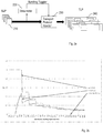
- the adaptive bundling may exploit a "traffic meter" 220 that provides runtime measurement of the ULP arrival rate, Ar. Such a traffic meter may then feed a decision state-machine that drives a bundling machine.
- Figure 2a illustrates an example of an architecture for an adaptive bundling mechanism comprising a data meter, 220, a transport protocol handler 230 and a bundling toggler.
- the data meter entity 220 is a tool that measures the amount of ULPs being sent from the application, or an upper layer protocol to the transport layer protocol. According to e.g. an inference mechanism, the data meter entity 220 provides the bundling toggler with information that is used for deciding when bundling is to be done and/or when bundling is not to be done. The data meter entity 220 may calculate the amount of traffic continuously; calculation can be done in terms of ULP/sec or bytes/sec.
- the choice of Y can be done statically or run-time, being decided for instance by the total load on computing resources used for TLP, or otherwise by the total load of the transport layer, or by any other function f that behaves according to the law ⁇ ⁇ f ⁇ load max load ⁇ .
- the maximum delay is equal to no-bundling case up to the threshold value is chosen, when the threshold value is exceeded it gets the same value as the adopted bundling strategy.
- the computational cost for adaptive bundling is denoted Cab, and the computational delay for employing adaptive bundling is denoted Dab.
- the Cab is proportional to the TLP transmission rate.
- the transport protocol handler 230 is the object or arrangement implementing a transport protocol that is used for transporting multiple instances of ULPs. Depending on the network architecture, the transport protocol handler 230 may use different technologies, as for instance Internet Protocol, IP, Transmission Control Protocol, TCP, Stream Control Transmission Protocol, SCTP.
- the bundling toggler is an interface that allows bundling functionality belonging to the transport protocol handler 230 to be enabled and/or disabled.
- the data flow is assumed to be originated as a stream of ULPs from an external upper layer client such as the application described above, then ULPs are received by the data meter 220 as well as by the transport protocol handler 230. ULPs are packed into a TLP inside the transport protocol handler 230, and depending on the Data Meter decision, they are bundled or not.
- the adaptive bundling is getting the benefit of bundling technics when it is worth to use it. This creates a unique behaviour both in Central Processing Unit, CPU, usage and in traffic profile.
- pre-bundling is introducing a fixed delay, equals the bundling supervision time, per ULP, so once the inter-arrival packet time is higher than the bundling supervision time, and such a delay is the highest latency introduced by the algorithm, from now called M ⁇ . It is decreasing its weight directly to the inter-arrival packet time.
- Post-bundling instead, starts to introduce bundling supervision time once the ULP inter-arrival time is less than the bundling supervision time itself. Increasing the inter-arrival packet time will let the delay of post-bundling behave as the pre-bundling one.
- the adaptive bundling delay remains zero until the ULP inter-arrival time is higher enough to activate the bundling toggle and then it should show a behaviour aligned to previously known standard bundling algorithms. See also the graph in figure 2b illustrating delay as a function of Ar.
- the theoretical computation of introduced latency is visible in the real traffic profile. Sniffing the round-trip delay between a traffic generator and a node using different bundling algorithms is able both to show the latency as described theoretically before and the protocol computing contribution to the delay, expected to increase exponentially for the no-bundling algorithm once the ULP inter-arrival time begins significant.
- Embodiments herein also relate to a transmission entity for transmitting one or more data packets to a receiving entity, wherein the transmitting entity and the receiving entity are operable in a communication network.
- the transmitting entity has the same technical features, objects and advantages as the method performed by the transmitting entity. The transmitting entity will thus only be described in brief in order to avoid unnecessary repetition. Embodiments of the transmitting entity will be briefly described with reference to figures 3 and 4 .
- Figures 3 and 4 illustrate the transmitting entity 300, 400 being configured for receiving, from an application, a ULP, to be transmitted by means of a TLP, to the receiving entity; bundling the received ULP together with one or more additional received ULPs in a TLP when a rate of incoming data, bytes or ULPs from the application meets a threshold; and transmitting the TLP to the receiving entity.
- FIG. 3 illustrates the transmitting entity 300 comprising a processor 321 and memory 322, the memory comprising instructions, e.g. by means of a computer program 323, which when executed by the processor 321 causes the transmitting entity 300 to receive, from an application, a ULP, to be transmitted by means of a TLP, to the receiving entity; to bundle the received ULP together with one or more additional received ULPs in a TLP when a rate of incoming data, bytes or ULPs from the application meets a threshold; and to transmit the TLP to the receiving entity.
- Figure 3 also illustrates the transmitting entity 300 comprising a memory 310. It shall be pointed out that figure 3 is merely an exemplifying illustration and memory 310 may be optional, be a part of the memory 322 or be a further memory of the transmitting entity 300.
- the memory may for example comprise information relating to the transmitting entity 300, to statistics of operation of the transmitting entity 300, just to give a couple of illustrating examples.
- Figure 3 further illustrates the transmitting entity 300 comprising processing means 320, which comprises the memory 322 and the processor 321. Still further, figure 3 illustrates the transmitting entity 300 comprising a communication unit 330.
- the communication unit 330 may comprise an interface through which the transmitting entity 300 communicates with other nodes or entities of the communication network as well as other communication units.
- Figure 3 also illustrates the transmitting entity 300 comprising further functionality 340.
- the further functionality 340 may comprise hardware of software necessary for the transmitting entity 300 to perform different tasks that are not disclosed herein.
- FIG 4 An alternative exemplifying realisation, or implementation, of the transmitting entity 300, 400 is illustrated in figure 4.
- Figure 4 illustrates the transmitting entity 400 comprising a receiving unit 403 for receiving, from an application, a ULP, to be transmitted by means of a TLP, to the receiving entity.
- Figure 4 also illustrates the transmitting entity 400 comprising a bundling unit 404 for bundling the received ULP together with one or more additional received ULPs in a TLP when a rate of incoming data, bytes or ULPs from the application meets a threshold; and a transmitting unit 405 for transmitting the TLP to the receiving entity.
- the transmitting entity 400 is also illustrated comprising a communication unit 401.
- the transmitting entity 400 is adapted to communicate with other nodes and/or entities in the communication network.
- the communication unit 401 may comprise more than one receiving arrangement.
- the communication unit 401 may be connected to both a wire and an antenna, by means of which the transmitting entity 400 is enabled to communicate with other nodes and/or entities in the communication network.
- the communication unit 401 may comprise more than one transmitting arrangement, which in turn is connected to both a wire and an antenna, by means of which the transmitting entity 400 is enabled to communicate with other nodes and/or entities in the communication network.
- the transmitting entity 400 further comprises a memory 402 for storing data.
- the transmitting entity 400 may comprise a control or processing unit (not shown) which in turn is connected to the different units 403-405. It shall be pointed out that this is merely an illustrative example and the transmitting entity 400 may comprise more, less or other units or modules which execute the functions of the transmitting entity 400 in the same manner as the units illustrated in figure 4 .
- figure 4 merely illustrates various functional units in the transmitting entity 400 in a logical sense.
- the functions in practice may be implemented using any suitable software and hardware means/circuits etc.
- the embodiments are generally not limited to the shown structures of the transmitting entity 400 and the functional units.
- the previously described exemplary embodiments may be realised in many ways.
- one embodiment includes a computer-readable medium having instructions stored thereon that are executable by the control or processing unit for executing the method steps in the transmitting entity 400.
- the instructions executable by the computing system and stored on the computer-readable medium perform the method steps of the transmitting entity 400 as set forth in the claims.
- the transmitting entity has the same possible advantages as the method performed by the transmitting entity.
- One possible advantage is adaptive bundling may provide a better CPU resource utilisation than no-bundling option at a similar latency.
- Another possible advantage is that adaptive bundling may provide a higher traffic capacity than no-bundling and a better latency with high traffic figures.
- Still a possible advantage is that adaptive bundling may provide latency than any other bundling mechanism with low and medium traffic figures, and the same latency than other bundling mechanism at high traffic figures.
- adaptive bundling may provide the possibility to tune-up the bundling feature according to the actual CPU utilisation, thus optimising the resource utilisation.
- the transmitting entity is further configured for inserting the received ULP in the TLP without bundling it together with any additional received ULPs when the rate of incoming bytes or ULPs does not meet the threshold, and transmitting the TLP to the receiving entity.
- the bundling comprises determining the rate of incoming data, bytes or ULPs from the application.
- the threshold is determined at least partly based on whether the bundling scheme is based on pre-bundling or post-bundling, wherein (a) pre-bundling comprises starting a supervision timer at the reception of the ULP from the application and waiting until the timer expires or the TLP is full before transmitting the TLP, and (b) post-bundling comprises transmitting the ULP as soon as it is received from the application in the TLP, starting the supervision timer and waiting until the supervision timer expires or the TLP is full until a subsequent TLP is transmitted comprising one or more ULPs.
- the threshold is determined at least partly based on one or more of (i) a supervision timer indicating a period of time the network node should wait, unless the TLP is full, before transmitting one or more received ULPs, (ii) the size of the TLP, (iii) the size of the ULP, (iv) the number of ULPs, (v) the rate of incoming data, bytes or ULPs, (vi) computational cost for not employing bundling, (vii) computational cost for employing bundling, (viii) computational cost for the supervision timer, (ix) computational delay for not employing bundling, and (x) computational delay for employing bundling.
- FIG. 5 schematically shows an embodiment of an arrangement 500 in transmitting entity 400.
- a processing unit 506 e.g. with a Digital Signal Processor, DSP.
- the processing unit 506 may be a single unit or a plurality of units to perform different actions of procedures described herein.
- the arrangement 500 of the transmitting entity 400 may also comprise an input unit 502 for receiving signals from other entities, and an output unit 504 for providing signal(s) to other entities.
- the input unit and the output unit may be arranged as an integrated entity or as illustrated in the example of figure 4 , as one or more interfaces 401.
- the arrangement 500 in the transmitting entity 400 comprises at least one computer program product 508 in the form of a non-volatile memory, e.g. an Electrically Erasable Programmable Read-Only Memory, EEPROM, a flash memory and a hard drive.
- the computer program product 508 comprises a computer program 510, which comprises code means, which when executed in the processing unit 506 in the arrangement 500 in the transmitting entity 400 causes the transmitting entity to perform the actions e.g. of the procedure described earlier in conjunction with figures 1a-1b .
- the computer program 510 may be configured as a computer program code structured in computer program modules 510a-510e.
- the code means in the computer program of the arrangement 500 in the transmitting entity 400 comprises a receiving unit, or module, for receiving, from an application, a ULP, to be transmitted by means of a TLP, to the receiving entity; and a bundling unit, or module, for bundling the received ULP together with one or more additional received ULPs in a TLP when a rate of incoming data, bytes or ULPs from the application meets a threshold.
- the computer program of the arrangement 500 in the transmitting entity 400 comprises a transmitting unit, or module, for transmitting the TLP to the receiving entity.
- the computer program modules could essentially perform the actions of the flow illustrated in figures 1a-1b , to emulate the transmitting entity 400.
- the different computer program modules when executed in the processing unit 506, they may correspond to the units 403-405 of figure 4 .
- code means in the respective embodiments disclosed above in conjunction with figure 4 are implemented as computer program modules which when executed in the respective processing unit causes the transmitting entity to perform the actions described above in the conjunction with figures mentioned above, at least one of the code means may in alternative embodiments be implemented at least partly as hardware circuits.
- the processor may be a single Central Processing Unit, CPU, but could also comprise two or more processing units.
- the processor may include general purpose microprocessors; instruction set processors and/or related chips sets and/or special purpose microprocessors such as Application Specific Integrated Circuits, ASICs.
- the processor may also comprise board memory for caching purposes.
- the computer program may be carried by a computer program product connected to the processor.
- the computer program product may comprise a computer readable medium on which the computer program is stored.
- the computer program product may be a flash memory, a Random-Access Memory RAM, Read-Only Memory, ROM, or an EEPROM, and the computer program modules described above could in alternative embodiments be distributed on different computer program products in the form of memories within the transmitting entity.
Landscapes
- Engineering & Computer Science (AREA)
- Computer Networks & Wireless Communication (AREA)
- Signal Processing (AREA)
- Computer Security & Cryptography (AREA)
- Mobile Radio Communication Systems (AREA)
- Data Exchanges In Wide-Area Networks (AREA)
Claims (10)
- Verfahren (100), das von einer sendenden Einheit zum Übertragen eines oder mehrerer Datenpakete an eine Empfangseinheit durchgeführt wird, wobei die sendende Einheit und die Empfangseinheit in einem Kommunikationsnetzwerk betrieben werden können, wobei das Verfahren (100) Folgendes umfasst:- Empfangen (110), von einer Anwendung, eines Benutzerschichtpakets, ULP, das mittels eines Transportschichtpakets, TLP, an die Empfangseinheit zu übertragen ist,- wenn eine Rate von eingehenden Daten, Bytes oder ULP von der Anwendung einen Schwellenwert erreicht, Bündeln (130) der empfangenen ULP zusammen mit einem oder mehreren zusätzlichen empfangenen ULP in einem TLP und, wenn die Rate von eingehenden Daten, Bytes oder ULP den Schwellenwert nicht erreicht, Einfügen (120) des empfangenen ULP in das TLP ohne Bündeln des empfangenen ULP zusammen mit zusätzlichen empfangenen ULP, und- Übertragen (140) des TLP an die Empfangseinheit,dadurch gekennzeichnet, dass der Schwellenwert zumindest teilweise basierend auf Folgendem ermittelt wird:(i) Rechenaufwand für Nichtanwenden des Bündelns (130), (ii) Rechenaufwand für Anwenden des Bündelns (130), (iii) Rechenaufwand für einen Überwachungszeitgeber, der einen Zeitraum angibt, den die sendende Einheit abwarten soll, außer das TLP ist voll, bevor sie eine oder mehrere empfangene ULP überträgt, (iv) Rechenverzögerung für Nichtanwenden des Bündelns (130) und (v) Rechenverzögerung für Anwenden des Bündelns (130).
- Verfahren (100) nach Anspruch 1, wobei das Bündeln (130) das Ermitteln der Rate von eingehenden Daten, Bytes oder ULP von der Anwendung umfasst.
- Verfahren (100) nach einem der Ansprüche 1 oder 2, wobei der Schwellenwert ferner zumindest teilweise darauf basierend ermittelt wird, ob ein Bündelungsschema auf Vor-Bündeln oder Nach-Bündeln basiert, wobei (a) das Vor-Bündeln das Starten des Überwachungszeitgebers beim Empfang des ULP von der Anwendung und das Warten, bis der Überwachungszeitgeber abläuft oder das TLP voll ist, bevor das TLP übertragen wird, umfasst, und (b) das Nach-Bündeln das Übertragen des ULP, sobald das ULP von der Anwendung in dem TLP empfangen wird, Starten des Überwachungszeitgebers und Warten, bis der Überwachungszeitgeber abläuft oder das TLP voll ist, bis ein nachfolgendes TLP übertragen wird, das ein oder mehrere ULP umfasst, umfasst.
- Verfahren (100) nach Anspruch 1, wobei der Schwellenwert ferner zumindest teilweise basierend auf einem oder mehreren der Folgenden ermittelt wird: (i) der Überwachungszeitgeber gibt einen Zeitraum an, den die sendende Einheit abwarten soll, außer das TLP ist voll, bevor sie eine oder mehrere empfangene ULP überträgt, (ii) einer Größe des TLP, (iii) einer Größe des ULP, (iv) einer Anzahl der ULP und (v) der Rate der eingehenden Daten, Bytes oder ULP.
- Sendende Einheit (300, 400) zum Übertragen eines oder mehrerer Datenpakete an eine Empfangseinheit, wobei die sendende Einheit (300, 400) und die Empfangseinheit in einem Kommunikationsnetzwerk betrieben werden können, wobei die sendende Einheit (300, 400) konfiguriert ist, um:- von einer Anwendung ein Benutzerschichtpaket, ULP, das mittels eines Transportschichtpakets, TLP, an die Empfangseinheit zu übertragen ist, zu empfangen,- wenn eine Rate von eingehenden Daten, Bytes oder ULP von der Anwendung einen Schwellenwert erreicht, das empfangene ULP zusammen mit einem oder mehreren zusätzlichen empfangenen ULP in einem TLP zu bündeln und, wenn die Rate von eingehenden Daten, Bytes oder ULP den Schwellenwert nicht erreicht, das empfangene ULP in das TLP ohne Bündeln des empfangenen ULP zusammen mit zusätzlichen empfangenen ULP einzufügen, und- das TLP an die Empfangseinheit zu übertragen,dadurch gekennzeichnet, dass die sendende Einheit (300, 400) ferner konfiguriert ist, den Schwellenwert zumindest teilweise basierend auf Folgendem zu ermitteln:(i) Rechenaufwand für Nichtanwenden des Bündelns,(ii) Rechenaufwand für Anwenden des Bündelns,(iii) Rechenaufwand für einen Überwachungszeitgeber, der einen Zeitraum angibt, den die sendende Einheit abwarten soll, außer das TLP ist voll, bevor sie eine oder mehrere empfangene ULP überträgt,(iv) Rechenverzögerung für Nichtanwenden des Bündelns und (v) Rechenverzögerung für Anwenden des Bündelns.
- Sendende Einheit (300, 400) nach Anspruch 5, wobei das Bündeln das Ermitteln der Rate von eingehenden Daten, Bytes oder ULP von der Anwendung umfasst.
- Sendende Einheit (300, 400) nach Anspruch 5, wobei der Schwellenwert ferner zumindest teilweise darauf basierend ermittelt wird, ob ein Bündelungsschema auf Vor-Bündeln oder Nach-Bündeln basiert, wobei (a) das Vor-Bündeln das Starten des Überwachungszeitgebers beim Empfang des ULP von der Anwendung und das Warten, bis der Überwachungszeitgeber abläuft oder das TLP voll ist, bevor das TLP übertragen wird, umfasst, und (b) das Nach-Bündeln das Übertragen des ULP, sobald das ULP von der Anwendung in dem TLP empfangen wird, Starten des Überwachungszeitgebers und Warten, bis der Überwachungszeitgeber abläuft oder das TLP voll ist, bis ein nachfolgendes TLP übertragen wird, das ein oder mehrere ULP umfasst, umfasst.
- Sendende Einheit (300, 400) nach einem der Ansprüche 5-7, wobei der Schwellenwert ferner zumindest teilweise basierend auf einem oder mehreren der Folgenden ermittelt wird: (i) der Überwachungszeitgeber gibt einen Zeitraum an, den die sendende Einheit (300, 400) abwarten soll, außer das TLP ist voll, bevor sie eine oder mehrere empfangene ULP überträgt, (ii) einer Größe des TLP, (iii) einer Größe des ULP, (iv) einer Anzahl der ULP und (v) der Rate der eingehenden Daten, Bytes oder ULP.
- Computerprogramm (510), umfassend ein computerlesbares Codemittel, das, wenn es in einer Verarbeitungseinheit (506) ausgeführt wird, die in einer Anordnung (500) in einer sendenden Einheit (400) nach den Ansprüchen 5-8 umfasst ist, bewirkt, dass der Access Point (400) das entsprechende Verfahren nach einem der Ansprüche 1-4 durchführt.
- Computerprogrammprodukt (508), umfassend das Computerprogramm (510) nach Anspruch 9.
Applications Claiming Priority (1)
| Application Number | Priority Date | Filing Date | Title |
|---|---|---|---|
| PCT/EP2015/073649 WO2017063672A1 (en) | 2015-10-13 | 2015-10-13 | A transmitting entity and method performed thereby for transmitting one or more data packets to a receiving entity |
Publications (2)
| Publication Number | Publication Date |
|---|---|
| EP3363174A1 EP3363174A1 (de) | 2018-08-22 |
| EP3363174B1 true EP3363174B1 (de) | 2020-04-15 |
Family
ID=54293256
Family Applications (1)
| Application Number | Title | Priority Date | Filing Date |
|---|---|---|---|
| EP15778961.1A Active EP3363174B1 (de) | 2015-10-13 | 2015-10-13 | Sendende einheit und damit durchgeführtes verfahren zur übertragung einer oder mehrerer datenpakete an eine empfangseinheit |
Country Status (4)
| Country | Link |
|---|---|
| US (1) | US10516770B2 (de) |
| EP (1) | EP3363174B1 (de) |
| CN (1) | CN108141431B (de) |
| WO (1) | WO2017063672A1 (de) |
Families Citing this family (1)
| Publication number | Priority date | Publication date | Assignee | Title |
|---|---|---|---|---|
| EP3443807B1 (de) * | 2016-04-12 | 2019-08-14 | Telefonaktiebolaget LM Ericsson (PUBL) | Mehrere sctp-assoziationen pro s1ap-verbindung und bewegen einer s1ap-signalisierungsverbindung zwischen sctp-assoziationen |
Family Cites Families (15)
| Publication number | Priority date | Publication date | Assignee | Title |
|---|---|---|---|---|
| AU2001292798A1 (en) * | 2000-09-28 | 2002-04-08 | Motorola, Inc., A Corporation Of The State Of Delaware | Adaptive packet bundling for system performance optimization |
| US7388866B2 (en) * | 2002-03-07 | 2008-06-17 | Broadcom Corporation | System and method for expediting upper layer protocol (ULP) connection negotiations |
| US7839876B1 (en) * | 2006-01-25 | 2010-11-23 | Marvell International Ltd. | Packet aggregation |
| ATE438991T1 (de) | 2006-03-28 | 2009-08-15 | Ericsson Telefon Ab L M | Verfahren und abschlussknoten zur bündelung mehrerer nachrichten zu einem paket |
| JP5075784B2 (ja) * | 2008-10-01 | 2012-11-21 | 株式会社エヌ・ティ・ティ・ドコモ | 移動通信システム及び送信側ノード |
| US20100135326A1 (en) * | 2008-11-21 | 2010-06-03 | Qualcomm Incorporated | Technique for bundle creation |
| US8509193B2 (en) * | 2009-07-21 | 2013-08-13 | Microsoft Corporation | Packet aggregation |
| JP2011029905A (ja) * | 2009-07-24 | 2011-02-10 | Fujifilm Corp | 撮像装置、方法およびプログラム |
| WO2011025438A1 (en) * | 2009-08-25 | 2011-03-03 | Telefonaktiebolaget L M Ericsson (Publ) | Using the ecn mechanism to signal congestion directly to the base station |
| US20110199899A1 (en) | 2010-02-16 | 2011-08-18 | Lime Brokerage Holding Llc | Rate-Adaptive Bundling of Data in a Packetized Communication System |
| CN102571317B (zh) * | 2012-01-06 | 2016-04-27 | 因诺微科技(天津)有限公司 | 软件无线电系统中基于pci总线的数据同步方法及系统 |
| US9380635B2 (en) * | 2012-01-09 | 2016-06-28 | Google Technology Holdings LLC | Dynamic TCP layer optimization for real-time field performance |
| CN103312682B (zh) * | 2012-03-16 | 2016-12-14 | 中兴通讯股份有限公司 | 网关安全接入的方法及系统 |
| US9350676B2 (en) * | 2012-12-11 | 2016-05-24 | Qualcomm Incorporated | Method and apparatus for classifying flows for compression |
| CN104660573A (zh) * | 2013-11-25 | 2015-05-27 | 上海益尚信息科技有限公司 | 一种用于sctp协议的低信息交互的多基站置 |
-
2015
- 2015-10-13 EP EP15778961.1A patent/EP3363174B1/de active Active
- 2015-10-13 CN CN201580083871.7A patent/CN108141431B/zh active Active
- 2015-10-13 WO PCT/EP2015/073649 patent/WO2017063672A1/en not_active Ceased
- 2015-10-13 US US15/763,593 patent/US10516770B2/en not_active Expired - Fee Related
Non-Patent Citations (1)
| Title |
|---|
| None * |
Also Published As
| Publication number | Publication date |
|---|---|
| WO2017063672A1 (en) | 2017-04-20 |
| EP3363174A1 (de) | 2018-08-22 |
| CN108141431A (zh) | 2018-06-08 |
| CN108141431B (zh) | 2021-02-26 |
| US10516770B2 (en) | 2019-12-24 |
| US20180270335A1 (en) | 2018-09-20 |
Similar Documents
| Publication | Publication Date | Title |
|---|---|---|
| US11316795B2 (en) | Network flow control method and network device | |
| EP2601765B1 (de) | Verfahren und vorrichtung zur reduzierung des overheads bei der datenübertragung | |
| US6894974B1 (en) | Method, apparatus, media, and signals for controlling packet transmission rate from a packet source | |
| US20170187641A1 (en) | Scheduler, sender, receiver, network node and methods thereof | |
| US8509074B1 (en) | System, method, and computer program product for controlling the rate of a network flow and groups of network flows | |
| US9900357B2 (en) | Rate control | |
| US20030169688A1 (en) | System and method for dynamic rate flow control | |
| Tai et al. | Making large scale deployment of RCP practical for real networks | |
| JP2009105981A (ja) | 帯域幅制御のためにデータ・パケット送信のタイミングを取る方法及びシステム | |
| US20100329117A1 (en) | Network Traffic Accelerator | |
| EP3582455B1 (de) | Verfahren und vorrichtung zur mehrfachen subflüssen-netzübertragung | |
| CN107682279B (zh) | 一种时延控制方法、装置及存储介质、程序产品 | |
| Kuriakose et al. | Analytical models for capacity estimation of IEEE 802.11 WLANs using DCF for internet applications | |
| CN102461093A (zh) | 管理业务负荷的方法 | |
| CN106936730A (zh) | 一种报文发送方法、tcp代理以及tcp客户端 | |
| CN110072254B (zh) | 一种数据的传输方法及其相关设备 | |
| EP2292060B1 (de) | Verfahren zur ermittlung einer optimalen formungsrate für einen neuen paketfluss | |
| EP3363174B1 (de) | Sendende einheit und damit durchgeführtes verfahren zur übertragung einer oder mehrerer datenpakete an eine empfangseinheit | |
| CN106789709B (zh) | 一种负载均衡的方法及装置 | |
| CN101753407B (zh) | 一种obs组帧方法和装置 | |
| WO2025031497A1 (zh) | 网络拥塞的控制方法和装置 | |
| Shewmaker et al. | TCP inigo: ambidextrous congestion control | |
| CN110290552B (zh) | 缓存深度的测量方法和装置、存储介质、电子装置 | |
| Eklund et al. | Efficient scheduling to reduce latency for signaling traffic using CMT-SCTP | |
| JP2008236709A (ja) | 通信品質制御方法と通信品質制御装置および通信システムとプログラム |
Legal Events
| Date | Code | Title | Description |
|---|---|---|---|
| STAA | Information on the status of an ep patent application or granted ep patent |
Free format text: STATUS: THE INTERNATIONAL PUBLICATION HAS BEEN MADE |
|
| PUAI | Public reference made under article 153(3) epc to a published international application that has entered the european phase |
Free format text: ORIGINAL CODE: 0009012 |
|
| STAA | Information on the status of an ep patent application or granted ep patent |
Free format text: STATUS: REQUEST FOR EXAMINATION WAS MADE |
|
| 17P | Request for examination filed |
Effective date: 20180417 |
|
| AK | Designated contracting states |
Kind code of ref document: A1 Designated state(s): AL AT BE BG CH CY CZ DE DK EE ES FI FR GB GR HR HU IE IS IT LI LT LU LV MC MK MT NL NO PL PT RO RS SE SI SK SM TR |
|
| AX | Request for extension of the european patent |
Extension state: BA ME |
|
| DAV | Request for validation of the european patent (deleted) | ||
| DAX | Request for extension of the european patent (deleted) | ||
| GRAP | Despatch of communication of intention to grant a patent |
Free format text: ORIGINAL CODE: EPIDOSNIGR1 |
|
| STAA | Information on the status of an ep patent application or granted ep patent |
Free format text: STATUS: GRANT OF PATENT IS INTENDED |
|
| INTG | Intention to grant announced |
Effective date: 20191211 |
|
| GRAS | Grant fee paid |
Free format text: ORIGINAL CODE: EPIDOSNIGR3 |
|
| GRAA | (expected) grant |
Free format text: ORIGINAL CODE: 0009210 |
|
| STAA | Information on the status of an ep patent application or granted ep patent |
Free format text: STATUS: THE PATENT HAS BEEN GRANTED |
|
| AK | Designated contracting states |
Kind code of ref document: B1 Designated state(s): AL AT BE BG CH CY CZ DE DK EE ES FI FR GB GR HR HU IE IS IT LI LT LU LV MC MK MT NL NO PL PT RO RS SE SI SK SM TR |
|
| REG | Reference to a national code |
Ref country code: CH Ref legal event code: EP |
|
| REG | Reference to a national code |
Ref country code: DE Ref legal event code: R096 Ref document number: 602015050777 Country of ref document: DE |
|
| REG | Reference to a national code |
Ref country code: IE Ref legal event code: FG4D |
|
| REG | Reference to a national code |
Ref country code: AT Ref legal event code: REF Ref document number: 1258636 Country of ref document: AT Kind code of ref document: T Effective date: 20200515 |
|
| REG | Reference to a national code |
Ref country code: NL Ref legal event code: MP Effective date: 20200415 |
|
| REG | Reference to a national code |
Ref country code: LT Ref legal event code: MG4D |
|
| PG25 | Lapsed in a contracting state [announced via postgrant information from national office to epo] |
Ref country code: IS Free format text: LAPSE BECAUSE OF FAILURE TO SUBMIT A TRANSLATION OF THE DESCRIPTION OR TO PAY THE FEE WITHIN THE PRESCRIBED TIME-LIMIT Effective date: 20200815 Ref country code: FI Free format text: LAPSE BECAUSE OF FAILURE TO SUBMIT A TRANSLATION OF THE DESCRIPTION OR TO PAY THE FEE WITHIN THE PRESCRIBED TIME-LIMIT Effective date: 20200415 Ref country code: PT Free format text: LAPSE BECAUSE OF FAILURE TO SUBMIT A TRANSLATION OF THE DESCRIPTION OR TO PAY THE FEE WITHIN THE PRESCRIBED TIME-LIMIT Effective date: 20200817 Ref country code: SE Free format text: LAPSE BECAUSE OF FAILURE TO SUBMIT A TRANSLATION OF THE DESCRIPTION OR TO PAY THE FEE WITHIN THE PRESCRIBED TIME-LIMIT Effective date: 20200415 Ref country code: LT Free format text: LAPSE BECAUSE OF FAILURE TO SUBMIT A TRANSLATION OF THE DESCRIPTION OR TO PAY THE FEE WITHIN THE PRESCRIBED TIME-LIMIT Effective date: 20200415 Ref country code: NL Free format text: LAPSE BECAUSE OF FAILURE TO SUBMIT A TRANSLATION OF THE DESCRIPTION OR TO PAY THE FEE WITHIN THE PRESCRIBED TIME-LIMIT Effective date: 20200415 Ref country code: NO Free format text: LAPSE BECAUSE OF FAILURE TO SUBMIT A TRANSLATION OF THE DESCRIPTION OR TO PAY THE FEE WITHIN THE PRESCRIBED TIME-LIMIT Effective date: 20200715 Ref country code: GR Free format text: LAPSE BECAUSE OF FAILURE TO SUBMIT A TRANSLATION OF THE DESCRIPTION OR TO PAY THE FEE WITHIN THE PRESCRIBED TIME-LIMIT Effective date: 20200716 |
|
| REG | Reference to a national code |
Ref country code: AT Ref legal event code: MK05 Ref document number: 1258636 Country of ref document: AT Kind code of ref document: T Effective date: 20200415 |
|
| PG25 | Lapsed in a contracting state [announced via postgrant information from national office to epo] |
Ref country code: BG Free format text: LAPSE BECAUSE OF FAILURE TO SUBMIT A TRANSLATION OF THE DESCRIPTION OR TO PAY THE FEE WITHIN THE PRESCRIBED TIME-LIMIT Effective date: 20200715 Ref country code: RS Free format text: LAPSE BECAUSE OF FAILURE TO SUBMIT A TRANSLATION OF THE DESCRIPTION OR TO PAY THE FEE WITHIN THE PRESCRIBED TIME-LIMIT Effective date: 20200415 Ref country code: LV Free format text: LAPSE BECAUSE OF FAILURE TO SUBMIT A TRANSLATION OF THE DESCRIPTION OR TO PAY THE FEE WITHIN THE PRESCRIBED TIME-LIMIT Effective date: 20200415 Ref country code: HR Free format text: LAPSE BECAUSE OF FAILURE TO SUBMIT A TRANSLATION OF THE DESCRIPTION OR TO PAY THE FEE WITHIN THE PRESCRIBED TIME-LIMIT Effective date: 20200415 |
|
| PG25 | Lapsed in a contracting state [announced via postgrant information from national office to epo] |
Ref country code: AL Free format text: LAPSE BECAUSE OF FAILURE TO SUBMIT A TRANSLATION OF THE DESCRIPTION OR TO PAY THE FEE WITHIN THE PRESCRIBED TIME-LIMIT Effective date: 20200415 |
|
| REG | Reference to a national code |
Ref country code: DE Ref legal event code: R097 Ref document number: 602015050777 Country of ref document: DE |
|
| PG25 | Lapsed in a contracting state [announced via postgrant information from national office to epo] |
Ref country code: AT Free format text: LAPSE BECAUSE OF FAILURE TO SUBMIT A TRANSLATION OF THE DESCRIPTION OR TO PAY THE FEE WITHIN THE PRESCRIBED TIME-LIMIT Effective date: 20200415 Ref country code: DK Free format text: LAPSE BECAUSE OF FAILURE TO SUBMIT A TRANSLATION OF THE DESCRIPTION OR TO PAY THE FEE WITHIN THE PRESCRIBED TIME-LIMIT Effective date: 20200415 Ref country code: ES Free format text: LAPSE BECAUSE OF FAILURE TO SUBMIT A TRANSLATION OF THE DESCRIPTION OR TO PAY THE FEE WITHIN THE PRESCRIBED TIME-LIMIT Effective date: 20200415 Ref country code: SM Free format text: LAPSE BECAUSE OF FAILURE TO SUBMIT A TRANSLATION OF THE DESCRIPTION OR TO PAY THE FEE WITHIN THE PRESCRIBED TIME-LIMIT Effective date: 20200415 Ref country code: EE Free format text: LAPSE BECAUSE OF FAILURE TO SUBMIT A TRANSLATION OF THE DESCRIPTION OR TO PAY THE FEE WITHIN THE PRESCRIBED TIME-LIMIT Effective date: 20200415 Ref country code: RO Free format text: LAPSE BECAUSE OF FAILURE TO SUBMIT A TRANSLATION OF THE DESCRIPTION OR TO PAY THE FEE WITHIN THE PRESCRIBED TIME-LIMIT Effective date: 20200415 Ref country code: IT Free format text: LAPSE BECAUSE OF FAILURE TO SUBMIT A TRANSLATION OF THE DESCRIPTION OR TO PAY THE FEE WITHIN THE PRESCRIBED TIME-LIMIT Effective date: 20200415 Ref country code: CZ Free format text: LAPSE BECAUSE OF FAILURE TO SUBMIT A TRANSLATION OF THE DESCRIPTION OR TO PAY THE FEE WITHIN THE PRESCRIBED TIME-LIMIT Effective date: 20200415 |
|
| PLBE | No opposition filed within time limit |
Free format text: ORIGINAL CODE: 0009261 |
|
| STAA | Information on the status of an ep patent application or granted ep patent |
Free format text: STATUS: NO OPPOSITION FILED WITHIN TIME LIMIT |
|
| PG25 | Lapsed in a contracting state [announced via postgrant information from national office to epo] |
Ref country code: PL Free format text: LAPSE BECAUSE OF FAILURE TO SUBMIT A TRANSLATION OF THE DESCRIPTION OR TO PAY THE FEE WITHIN THE PRESCRIBED TIME-LIMIT Effective date: 20200415 Ref country code: SK Free format text: LAPSE BECAUSE OF FAILURE TO SUBMIT A TRANSLATION OF THE DESCRIPTION OR TO PAY THE FEE WITHIN THE PRESCRIBED TIME-LIMIT Effective date: 20200415 |
|
| 26N | No opposition filed |
Effective date: 20210118 |
|
| PG25 | Lapsed in a contracting state [announced via postgrant information from national office to epo] |
Ref country code: SI Free format text: LAPSE BECAUSE OF FAILURE TO SUBMIT A TRANSLATION OF THE DESCRIPTION OR TO PAY THE FEE WITHIN THE PRESCRIBED TIME-LIMIT Effective date: 20200415 |
|
| REG | Reference to a national code |
Ref country code: CH Ref legal event code: PL |
|
| PG25 | Lapsed in a contracting state [announced via postgrant information from national office to epo] |
Ref country code: MC Free format text: LAPSE BECAUSE OF FAILURE TO SUBMIT A TRANSLATION OF THE DESCRIPTION OR TO PAY THE FEE WITHIN THE PRESCRIBED TIME-LIMIT Effective date: 20200415 Ref country code: LU Free format text: LAPSE BECAUSE OF NON-PAYMENT OF DUE FEES Effective date: 20201013 |
|
| REG | Reference to a national code |
Ref country code: BE Ref legal event code: MM Effective date: 20201031 |
|
| PG25 | Lapsed in a contracting state [announced via postgrant information from national office to epo] |
Ref country code: LI Free format text: LAPSE BECAUSE OF NON-PAYMENT OF DUE FEES Effective date: 20201031 Ref country code: BE Free format text: LAPSE BECAUSE OF NON-PAYMENT OF DUE FEES Effective date: 20201031 Ref country code: CH Free format text: LAPSE BECAUSE OF NON-PAYMENT OF DUE FEES Effective date: 20201031 |
|
| PG25 | Lapsed in a contracting state [announced via postgrant information from national office to epo] |
Ref country code: IE Free format text: LAPSE BECAUSE OF NON-PAYMENT OF DUE FEES Effective date: 20201013 |
|
| REG | Reference to a national code |
Ref country code: DE Ref legal event code: R079 Ref document number: 602015050777 Country of ref document: DE Free format text: PREVIOUS MAIN CLASS: H04L0029060000 Ipc: H04L0065000000 |
|
| PG25 | Lapsed in a contracting state [announced via postgrant information from national office to epo] |
Ref country code: TR Free format text: LAPSE BECAUSE OF FAILURE TO SUBMIT A TRANSLATION OF THE DESCRIPTION OR TO PAY THE FEE WITHIN THE PRESCRIBED TIME-LIMIT Effective date: 20200415 Ref country code: MT Free format text: LAPSE BECAUSE OF FAILURE TO SUBMIT A TRANSLATION OF THE DESCRIPTION OR TO PAY THE FEE WITHIN THE PRESCRIBED TIME-LIMIT Effective date: 20200415 Ref country code: CY Free format text: LAPSE BECAUSE OF FAILURE TO SUBMIT A TRANSLATION OF THE DESCRIPTION OR TO PAY THE FEE WITHIN THE PRESCRIBED TIME-LIMIT Effective date: 20200415 |
|
| PG25 | Lapsed in a contracting state [announced via postgrant information from national office to epo] |
Ref country code: MK Free format text: LAPSE BECAUSE OF FAILURE TO SUBMIT A TRANSLATION OF THE DESCRIPTION OR TO PAY THE FEE WITHIN THE PRESCRIBED TIME-LIMIT Effective date: 20200415 |
|
| PGFP | Annual fee paid to national office [announced via postgrant information from national office to epo] |
Ref country code: DE Payment date: 20251029 Year of fee payment: 11 |
|
| PGFP | Annual fee paid to national office [announced via postgrant information from national office to epo] |
Ref country code: GB Payment date: 20251027 Year of fee payment: 11 |
|
| PGFP | Annual fee paid to national office [announced via postgrant information from national office to epo] |
Ref country code: FR Payment date: 20251027 Year of fee payment: 11 |