EP3363098B1 - Elektrischer antrieb - Google Patents
Elektrischer antrieb Download PDFInfo
- Publication number
- EP3363098B1 EP3363098B1 EP16779124.3A EP16779124A EP3363098B1 EP 3363098 B1 EP3363098 B1 EP 3363098B1 EP 16779124 A EP16779124 A EP 16779124A EP 3363098 B1 EP3363098 B1 EP 3363098B1
- Authority
- EP
- European Patent Office
- Prior art keywords
- electric drive
- control device
- rotor
- stator winding
- stator
- Prior art date
- Legal status (The legal status is an assumption and is not a legal conclusion. Google has not performed a legal analysis and makes no representation as to the accuracy of the status listed.)
- Active
Links
Images

Classifications
-
- H—ELECTRICITY
- H02—GENERATION; CONVERSION OR DISTRIBUTION OF ELECTRIC POWER
- H02K—DYNAMO-ELECTRIC MACHINES
- H02K11/00—Structural association of dynamo-electric machines with electric components or with devices for shielding, monitoring or protection
- H02K11/01—Structural association of dynamo-electric machines with electric components or with devices for shielding, monitoring or protection for shielding from electromagnetic fields, i.e. structural association with shields
- H02K11/014—Shields associated with stationary parts, e.g. stator cores
- H02K11/0141—Shields associated with casings, enclosures or brackets
-
- H—ELECTRICITY
- H02—GENERATION; CONVERSION OR DISTRIBUTION OF ELECTRIC POWER
- H02K—DYNAMO-ELECTRIC MACHINES
- H02K1/00—Details of the magnetic circuit
- H02K1/06—Details of the magnetic circuit characterised by the shape, form or construction
- H02K1/08—Salient poles
-
- H—ELECTRICITY
- H02—GENERATION; CONVERSION OR DISTRIBUTION OF ELECTRIC POWER
- H02K—DYNAMO-ELECTRIC MACHINES
- H02K1/00—Details of the magnetic circuit
- H02K1/06—Details of the magnetic circuit characterised by the shape, form or construction
- H02K1/12—Stationary parts of the magnetic circuit
- H02K1/14—Stator cores with salient poles
-
- H—ELECTRICITY
- H02—GENERATION; CONVERSION OR DISTRIBUTION OF ELECTRIC POWER
- H02K—DYNAMO-ELECTRIC MACHINES
- H02K1/00—Details of the magnetic circuit
- H02K1/06—Details of the magnetic circuit characterised by the shape, form or construction
- H02K1/12—Stationary parts of the magnetic circuit
- H02K1/14—Stator cores with salient poles
- H02K1/146—Stator cores with salient poles consisting of a generally annular yoke with salient poles
- H02K1/148—Sectional cores
-
- H—ELECTRICITY
- H02—GENERATION; CONVERSION OR DISTRIBUTION OF ELECTRIC POWER
- H02K—DYNAMO-ELECTRIC MACHINES
- H02K11/00—Structural association of dynamo-electric machines with electric components or with devices for shielding, monitoring or protection
- H02K11/0094—Structural association with other electrical or electronic devices
-
- H—ELECTRICITY
- H02—GENERATION; CONVERSION OR DISTRIBUTION OF ELECTRIC POWER
- H02K—DYNAMO-ELECTRIC MACHINES
- H02K11/00—Structural association of dynamo-electric machines with electric components or with devices for shielding, monitoring or protection
- H02K11/20—Structural association of dynamo-electric machines with electric components or with devices for shielding, monitoring or protection for measuring, monitoring, testing, protecting or switching
- H02K11/21—Devices for sensing speed or position, or actuated thereby
-
- H—ELECTRICITY
- H02—GENERATION; CONVERSION OR DISTRIBUTION OF ELECTRIC POWER
- H02K—DYNAMO-ELECTRIC MACHINES
- H02K11/00—Structural association of dynamo-electric machines with electric components or with devices for shielding, monitoring or protection
- H02K11/20—Structural association of dynamo-electric machines with electric components or with devices for shielding, monitoring or protection for measuring, monitoring, testing, protecting or switching
- H02K11/27—Devices for sensing current, or actuated thereby
-
- H—ELECTRICITY
- H02—GENERATION; CONVERSION OR DISTRIBUTION OF ELECTRIC POWER
- H02K—DYNAMO-ELECTRIC MACHINES
- H02K11/00—Structural association of dynamo-electric machines with electric components or with devices for shielding, monitoring or protection
- H02K11/30—Structural association with control circuits or drive circuits
- H02K11/33—Drive circuits, e.g. power electronics
-
- H—ELECTRICITY
- H02—GENERATION; CONVERSION OR DISTRIBUTION OF ELECTRIC POWER
- H02K—DYNAMO-ELECTRIC MACHINES
- H02K11/00—Structural association of dynamo-electric machines with electric components or with devices for shielding, monitoring or protection
- H02K11/30—Structural association with control circuits or drive circuits
- H02K11/35—Devices for recording or transmitting machine parameters, e.g. memory chips or radio transmitters for diagnosis
-
- H—ELECTRICITY
- H02—GENERATION; CONVERSION OR DISTRIBUTION OF ELECTRIC POWER
- H02K—DYNAMO-ELECTRIC MACHINES
- H02K3/00—Details of windings
- H02K3/04—Windings characterised by the conductor shape, form or construction, e.g. with bar conductors
- H02K3/18—Windings for salient poles
-
- H—ELECTRICITY
- H02—GENERATION; CONVERSION OR DISTRIBUTION OF ELECTRIC POWER
- H02K—DYNAMO-ELECTRIC MACHINES
- H02K3/00—Details of windings
- H02K3/44—Protection against moisture or chemical attack; Windings specially adapted for operation in liquid or gas
-
- H—ELECTRICITY
- H02—GENERATION; CONVERSION OR DISTRIBUTION OF ELECTRIC POWER
- H02K—DYNAMO-ELECTRIC MACHINES
- H02K2213/00—Specific aspects, not otherwise provided for and not covered by codes H02K2201/00 - H02K2211/00
- H02K2213/06—Machines characterised by the presence of fail safe, back up, redundant or other similar emergency arrangements
-
- H—ELECTRICITY
- H02—GENERATION; CONVERSION OR DISTRIBUTION OF ELECTRIC POWER
- H02K—DYNAMO-ELECTRIC MACHINES
- H02K2213/00—Specific aspects, not otherwise provided for and not covered by codes H02K2201/00 - H02K2211/00
- H02K2213/12—Machines characterised by the modularity of some components
-
- H—ELECTRICITY
- H02—GENERATION; CONVERSION OR DISTRIBUTION OF ELECTRIC POWER
- H02K—DYNAMO-ELECTRIC MACHINES
- H02K3/00—Details of windings
- H02K3/04—Windings characterised by the conductor shape, form or construction, e.g. with bar conductors
- H02K3/28—Layout of windings or of connections between windings
Definitions
- the invention relates to an electric drive.
- the US 2014/0191624 A1 and the WO 2014/089613 A1 each show an electric drive with a rotor and a stator using tooth coil technology, the stator having a number of individual tooth modules.
- a respective single-tooth module has a stator winding and a control device which is designed to generate a control signal for the stator winding.
- the WO 2015/134855 A1 shows an electric drive with a rotor and a segmented stator.
- the invention is based on the object of providing an electric drive which has the highest possible operational reliability against environmental influences.
- the invention solves this problem by an electric drive according to claim 1.
- the electric drive has a rotor.
- the electric drive also has a stator using toothed coil technology.
- toothed coil technology reference is also made to the relevant specialist literature.
- the stator has a number, for example a number between 3 and 36, of individual tooth modules.
- a respective single tooth module conventionally has a stator winding which is wound around an associated tooth.
- the single tooth module has a control device, for example comprising a microcontroller or an FPGA, which is designed to generate a control signal, in particular a pulse width modulated control signal, for example in the form of a control current or a control voltage, for the stator winding.
- a control device for example comprising a microcontroller or an FPGA, which is designed to generate a control signal, in particular a pulse width modulated control signal, for example in the form of a control current or a control voltage, for the stator winding.
- the single tooth module has a shielding device that surrounds the stator winding and the control device and hermetically seals it from the environment.
- a respective control device can have an electrical safety element in order, for example, to prevent an intermediate circuit short circuit in the event of a fault in the single-tooth module.
- a respective control device can have a power semiconductor module and/or an electrical energy storage device, for example in the form of a capacitor.
- a respective control device can have a device for detecting the rotor position, so that, for example, the control signal can be generated depending on the rotor position.
- a respective control device can have a power supply connection by means of which the single tooth module can be connected to a central power supply, for example in the form of a DC intermediate circuit.
- the electric drive can have a higher-level controller that is in data connection with the control devices of the respective individual tooth modules.
- the shielding device has or is a housing, in particular made of sheet steel, with the housing completely surrounding the stator winding and the control device.
- the shielding device is additionally formed from casting compound which contains soft magnetic particles, the casting compound completely surrounding the stator winding and the control device.
- the rotor can be provided with markings on its circumference to code the rotor position.
- the rotor can be designed as a permanent magnet rotor or reluctance rotor.
- the invention provides a highly integrated drive constructed from hermetically sealed and individually secured single tooth modules.
- the drive is advantageously constructed as a multi-phase drive consisting of n single-tooth modules in order to keep the loss of torque as low as possible if a single-tooth module fails.
- the winding of the electromechanical converter is advantageously designed as a single-layer winding in order to exclude damage to the adjacent winding in the event of heat development as a result of a winding short circuit or similar.
- Each single-tooth module can be provided with an integrated safety element (e.g. fuse or semiconductor fuse), which prevents the (common) intermediate circuit from being short-circuited in the event of a fault.
- an integrated safety element e.g. fuse or semiconductor fuse
- the shielding device is designed as a hermetic seal in such a way that it is not destroyed even in the event of an explosion of the power semiconductor module or a winding fire (e.g. as a result of a short circuit).
- An electronic module for example microcontroller or FPGA and associated peripherals
- An electronic module is advantageously integrated into the power semiconductor module or arranged directly on it.
- the rotor of the electromechanical energy converter is advantageously designed as a permanent magnet or reluctance rotor.
- Inputs of the higher-level control and regulation as well as the data connections between the individual tooth modules are advantageously electrically isolated.
- the hermetic seal can be designed in such a way that it ensures electromagnetic shielding of the enclosed electronics. It therefore acts as EMC shielding between the enclosed components and the environment.
- the single tooth modules are cast with a flame-retardant and electrically non-conductive compound (e.g. casting resin).
- the potting can be designed to be impermeable to liquids and gases.
- the casting is also filled with soft magnetic particles, such as magnetite. However, it is still not electrically conductive.
- the rotor can be provided with markings (optical or magnetic) on its circumference, from which the devices for detecting the rotor position can determine the angle of rotation of the rotor.
- control device control of the power semiconductors (gate driver), current measurement, PWM, temperature measurement, communication, protective functions (if protection against overcurrent is integrated, the separate fuse element can be omitted), detection of the rotor position ( in at least one single tooth module), control of the machine (if the single tooth module forms a master), emergency control of the machine (if all communication fails, each single tooth module can work independently).
- control of the power semiconductors gate driver
- current measurement PWM
- temperature measurement temperature measurement
- protective functions if protection against overcurrent is integrated, the separate fuse element can be omitted
- detection of the rotor position in at least one single tooth module
- control of the machine if the single tooth module forms a master
- emergency control of the machine if all communication fails, each single tooth module can work independently.
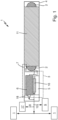
- Fig. 1 shows an example of a single single-tooth module 1 of a plurality of single-tooth modules, which are part of an electric drive, not shown in more detail.
- the electric drive also has a rotor, not shown, and a stator using tooth coil technology and a rotor, not shown, whereby the individual tooth modules 1 are part of the stator.
- the rotor can be designed, for example, as a permanent magnet rotor or reluctance rotor.
- a respective single tooth module 1 has a stator winding 2 which is wound around an associated tooth 11 made of electrical sheet metal.
- stator winding 2 which is wound around an associated tooth 11 made of electrical sheet metal.
- only winding heads of the stator winding 2 are shown schematically.
- the single tooth module 1 has a control device 3, which is designed to generate a control signal for the stator winding 2.
- the control device 3 has an electrical fuse element 18, a power semiconductor module 5, an electrical energy storage device 6, an optional device 7 for detecting the rotor position and an electronic module 16.
- the electronic module 16 can, for example, have a microcontroller or an FPGA and associated peripheral components, such as resistors, capacitors, coils, A/D converters, etc.
- the control device 3 has a power supply connection 8 for connecting to a power supply or a DC intermediate circuit 17.
- a data transmission connection 12 is provided, by means of which the control device 3 is data-connected to a higher-level controller 9.
- Fig. 3 shows an example of a possible topology of a logical connection of the single tooth modules 1 with the higher-level controller 9.
- One of the single tooth modules 1 is defined as the master and takes over the control of the electric drive and monitors the communication. If the master single-tooth module fails, one of the previous slave single-tooth modules is set as the new master single-tooth module and takes over control of the drive. If the higher-level controller 9 or the connection to it fails, the master starts an emergency program in which it regulates the modules to a predetermined operating point.
- a central device 13 can be provided for detecting the rotor position, which transmits the rotor position to the individual tooth modules via the respective data transmission connections 12, whereby the device 13 can also be integrated into one of the individual tooth modules. If the rotor position detection fails, the drive can also continue to be operated without a sensor. If the application allows it, a system for recording the rotor position can be completely dispensed with.
- control block 15 also being in the control 9 of Fig. 3 can be provided.
- the single tooth module 1 in Fig. 1 has a shielding device 4 in the form of a sheet steel housing that surrounds the stator winding 2 and the control device 3 and shields it from the environment.
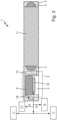
- Fig. 2 shows an embodiment of a single tooth module 1 'without device 7 for detecting the rotor position, in which the shielding device is formed from casting compound 10 which contains soft magnetic particles, the casting compound 10 surrounding the stator winding 2 and the control device 3.
- the housing 4 of the embodiment of Fig. 1 can also be filled with casting compound.
- the fuse element 18 prevents a short circuit in the DC intermediate circuit as soon as a serious error leads to the failure of a single-tooth module 1, 1 '. This results in increased operational safety.
- the electric drive can be, for example, a synchronous, synchronous reluctance or BLDC machine.
- the shielding device prevents electromagnetic influence on the electronics as well as the influence of the surrounding area through the single tooth module.
- the casting compound cannot catch fire and therefore prevents the cast components from burning off. This means that defects can occur as a result of mechanical influences, such as e.g. strong shocks or vibrations should be avoided.
- the drive will still function even if liquid enters the housing.
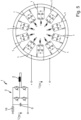
- Fig. 5 shows a highly schematic view of a plurality of single-tooth modules 1, which are connected in parallel to an intermediate voltage circuit or DC intermediate circuit.
- the single tooth modules 1 are evenly distributed over the circumference of the stator. It is understood that, in addition to the components 2, 18, 5 and 6 shown, there may typically be other components not shown, for example current sensors, voltage sensors, temperature sensors, (load) resistors, coils, capacitors, etc.
Landscapes
- Engineering & Computer Science (AREA)
- Power Engineering (AREA)
- Microelectronics & Electronic Packaging (AREA)
- Physics & Mathematics (AREA)
- Electromagnetism (AREA)
Description
- Die Erfindung betrifft einen elektrischen Antrieb.
- Die
US 2014/0191624 A1 und dieWO 2014/089613 A1 zeigen jeweils einen elektrischen Antrieb mit einem Rotor und einem Stator in Zahnspulentechnik, wobei der Stator eine Anzahl von Einzelzahnmodulen aufweist. Ein jeweiliges Einzelzahnmodul weist eine Statorwicklung und eine Steuereinrichtung auf, die dazu ausgebildet ist, ein Ansteuersignal für die Statorwicklung zu erzeugen. - Die
WO 2015/134855 A1 zeigt einen elektrischen Antrieb mit einem Rotor und einem segmentierten Stator. - Der Erfindung liegt die Aufgabe zugrunde, einen elektrischen Antrieb zur Verfügung zu stellen, der eine möglichst hohe Betriebssicherheit gegenüber Umwelteinflüssen aufweist.
- Die Erfindung löst diese Aufgabe durch einen elektrischen Antrieb nach Anspruch 1.
- Der elektrische Antrieb weist einen Rotor auf.
- Der elektrische Antrieb weist weiter einen Stator in Zahnspulentechnik auf. Hinsichtlich der Zahnspulentechnik sei auch auf die einschlägige Fachliteratur verwiesen. Der Stator weist eine Anzahl, beispielsweise eine Anzahl zwischen 3 und 36, von Einzelzahnmodulen auf.
- Ein jeweiliges Einzelzahnmodul weist herkömmlich eine Statorwicklung auf, die um einen zugehörigen Zahn gewickelt ist.
- Weiter weist das Einzelzahnmodul eine Steuereinrichtung auf, beispielsweise aufweisend einen Mikrocontroller oder ein FPGA, die dazu ausgebildet ist, ein Ansteuersignal, insbesondere ein pulsweitenmoduliertes Ansteuersignal, beispielsweise in Form eines Ansteuerstroms oder einer Ansteuerspannung, für die Statorwicklung zu erzeugen.
- Weiter weist das Einzelzahnmodul eine Abschirmeinrichtung auf, die die Statorwicklung und die Steuereinrichtung umgibt und hermetisch gegen die Umgebung abdichtet.
- Eine jeweilige Steuereinrichtung kann ein elektrisches Sicherungselement aufweisen, um beispielsweise im Fehlerfall des Einzelzahnmoduls einen Zwischenkreiskurzschluss zu verhindern.
- Eine jeweilige Steuereinrichtung kann ein Leistungshalbleitermodul und/oder einen elektrischen Energiespeicher, beispielsweise in Form eines Kondensators, aufweisen.
- Eine jeweilige Steuereinrichtung kann eine Einrichtung zur Erfassung der Rotorlage aufweisen, so dass beispielsweise eine rotorlageabhängige Erzeugung des Steuersignals möglich ist.
- Eine jeweilige Steuereinrichtung kann einen Energieversorgungsanschluss aufweisen, mittels dem das Einzelzahnmodul an eine zentrale Energieversorgung, beispielsweise in Form eines DC-Zwischenkreises, angeschlossen werden kann.
- Der elektrische Antrieb kann eine übergeordnete Steuerung aufweisen, die in Datenverbindung mit den Steuereinrichtungen der jeweiligen Einzelzahnmodule steht.
- Die Abschirmeinrichtung weist ein Gehäuse, insbesondere aus Stahlblech, auf bzw. ist ein solches, wobei das Gehäuse die Statorwicklung und die Steuereinrichtung vollständig umgibt.
- Die Abschirmeinrichtung ist zusätzlich aus Vergussmasse gebildet, die weichmagnetische Partikel enthält, wobei die Vergussmasse die Statorwicklung und die Steuereinrichtung vollständig umgibt.
- Der Rotor kann an seinem Umfang mit Markierungen zur Kodierung der Rotorlage versehen sein.
- Der Rotor kann als Permanentmagnetrotor oder Reluktanzrotor ausgeführt sein.
- Die Erfindung stellt einen hochintegrierten Antrieb aufgebaut aus hermetisch abgeriegelten und einzeln abgesicherten Einzelzahnmodulen zur Verfügung.
- Der Antrieb ist vorteilhaft als multiphasiger Antrieb aus n Einzelzahnmodulen aufgebaut, um den Verlust an Drehmoment beim Ausfall eines Einzelzahnmoduls möglichst gering zu halten.
- Die Wicklung des elektromechanischen Wandlers ist vorteilhaft als Einschichtwicklung ausgeführt, um bei Wärmeentwicklung infolge eines Wicklungskurzschlusses oder ähnlichem eine Beschädigung der benachbarten Wicklung auszuschließen.
- Jedes Einzelzahnmodul kann mit einem integrierten Sicherungselement (z.B. Schmelz- oder Halbleitersicherung) versehen sein, welches verhindert, dass im Fehlerfall der (gemeinsame) Zwischenkreis kurzgeschlossen wird.
- Die Abschirmeinrichtung als hermetische Abriegelung ist so ausgeführt, dass sie selbst bei einer Explosion des Leistungshalbleitermoduls oder eines Wicklungsbrandes (z.B. infolge eines Kurzschlusses) nicht zerstört wird.
- Ein Elektronikmodul (beispielsweise Mikrocontroller oder FPGA sowie zugehörige Peripherie) ist vorteilhaft in das Leistungshalbleitermodul integriert oder direkt an diesem angeordnet.
- Der Rotor des elektromechanischen Energiewandlers ist vorteilhaft als Permanentmagnet- oder Reluktanzrotor ausgeführt.
- Alle Verbindungen außerhalb des Einzelzahnmoduls können redundant vorhanden sein.
- Eingänge der übergeordneten Steuerung und Regelung sowie die Datenverbindungen zwischen den Einzelzahnmodulen sind vorteilhaft potenzialgetrennt ausgeführt.
- Die hermetische Abriegelung kann derart ausgeführt sein, dass durch sie eine elektromagnetische Schirmung der eingeschlossenen Elektronik sichergestellt wird. Sie wirkt dadurch als EMV Schirmung zwischen den eingeschlossenen Komponenten und der Umgebung.
- Die Einzelzahnmodule sind mit einer schwer entflammbaren und elektrisch nicht leitfähigen Masse vergossen (z.B. Gießharz). Der Verguss kann undurchlässig für Flüssigkeiten und Gase ausgeführt sein. Der Verguss ist zusätzlich mit weichmagnetischen Partikeln, wie z.B. Magnetit, gefüllt. Er ist jedoch weiterhin elektrisch nicht leitfähig.
- Der Rotor kann an seinem Umfang mit Markierungen (optisch oder magnetisch) versehen sein, aus denen die Einrichtungen zur Erfassung der Rotorlage den Drehwinkel des Rotors bestimmen können.
- Folgende Funktionen können beispielsweise ganz oder teilweise mittels der Steuereinrichtung realisiert sein: Ansteuerung der Leistungshalbleiter (Gate Treiber), Strommessung, PWM, Temperaturmessung, Kommunikation, Schutzfunktionen (wenn die Absicherung gegen Überstrom integriert ist, kann das separate Sicherungselement entfallen), Erfassung der Rotorlage (in mindestens einem Einzelzahnmodul), Regelung der Maschine (wenn das Einzelzahnmodul einen Master bildet), Notregelung der Maschine (beim Ausfall aller Kommunikation kann jedes Einzelzahnmodul autark arbeiten).
- Die Erfindung wird nachfolgend unter Bezugnahme auf die Zeichnungen detailliert beschrieben. Hierbei zeigen schematisch:
- Fig. 1
- ein erfindungsgemäßes Einzelzahnmodul gemäß einer ersten Ausführungsform,
- Fig. 2
- ein erfindungsgemäßes Einzelzahnmodul gemäß einer weiteren Ausführungsform,
- Fig. 3
- eine Topologie einer logischen Verschaltung der Einzelzahnmodule mit einer übergeordneten Steuereinheit gemäß einer ersten Ausführungsform,
- Fig. 4
- eine Topologie einer logischen Verschaltung der Einzelzahnmodule mit einer übergeordneten Steuereinheit gemäß einer weiteren Ausführungsform und
- Fig. 5
- schematisch eine Mehrzahl von Einzelzahnmodulen, die parallel an einen Spannungszwischenkreis angeschlossen sind.
-
Fig. 1 zeigt exemplarisch ein einzelnes Einzelzahnmodul 1 einer Mehrzahl von Einzelzahnmodulen, die Teil eines nicht näher dargestellten elektrischen Antriebs sind. Der elektrische Antrieb weist weiter einen nicht dargestellten Rotor und einen Stator in Zahnspulentechnik und einen nicht weiter dargestellten Rotor auf, wobei die Einzelzahnmodule 1 Teil des Stators sind. - Der Rotor kann beispielsweise als Permanentmagnetrotor oder Reluktanzrotor ausgeführt sein.
- Ein jeweiliges Einzelzahnmodul 1 weist eine Statorwicklung 2 auf, die um einen zugehörigen Zahn 11 aus Elektroblech gewickelt ist. Vorliegend sind aus Gründen der einfacheren Darstellung schematisch lediglich Wickelköpfe der Statorwicklung 2 gezeigt.
- Das Einzelzahnmodul 1 weist eine Steuereinrichtung 3 auf, die dazu ausgebildet ist, ein Ansteuersignal für die Statorwicklung 2 zu erzeugen. Die Steuereinrichtung 3 weist hierzu ein elektrisches Sicherungselement 18, ein Leistungshalbleitermodul 5, einen elektrischen Energiespeicher 6, eine optionale Einrichtung 7 zur Erfassung der Rotorlage und ein Elektronikmodul 16 auf. Das Elektronikmodul 16 kann beispielsweise einen Mikrocontroller oder ein FPGA und zugehörige Peripheriebauelemente aufweisen, wie Widerstände, Kondensatoren, Spulen, A/D-Wandler usw.
- Die Steuereinrichtung 3 weist einen Energieversorgungsanschluss 8 zum Anschließen an eine Energieversorgung bzw. einen DC-Zwischenkreis 17 auf.
- Weiter ist ein Datenübertragungsanschluss 12 vorgesehen, mittels dem die Steuereinrichtung 3 mit einer übergeordneten Steuerung 9 datenverbunden ist.
-
Fig. 3 zeigt beispielhaft eine mögliche Topologie einer logischen Verschaltung der Einzelzahnmodule 1 mit der übergeordneten Steuerung 9. Eines der Einzelzahnmodule 1 ist als Master festgelegt und übernimmt die Regelung des elektrischen Antriebs und überwacht die Kommunikation. Sollte das Master-Einzelzahnmodul ausfallen, so wird eines der bisherigen Slave-Einzelzahnmodule als neues Master-Einzelzahnmodul festgelegt und übernimmt die Regelung des Antriebs. Beim Ausfall der übergeordneten Steuerung 9 oder der Verbindung zu ihr startet der Master ein Notprogramm, in welchem er die Module auf einen vorgegebenen Betriebspunkt hin regelt. - Wenn die Einzelzahnmodule 1 keine Einrichtung 7 zur Erfassung der Rotorlage aufweisen, kann alternativ wie in
Fig. 4 gezeigt eine zentrale Einrichtung 13 zur Erfassung der Rotorlage vorgesehen sein, die die Rotorlage über die jeweiligen Datenübertragungsanschlüsse 12 zu den Einzelzahnmodulen überträgt, wobei die Einrichtung 13 auch in eines der Einzelzahnmodule integriert sein kann. Beim Ausfall der Rotorlageerfassung kann der Antrieb auch geberlos geregelt weiterbetrieben werden. Sollte es die Anwendung zulassen, kann auf ein System zur Erfassung der Rotorlage auch komplett verzichtet werden. - Weiter wird die Steuerung 9 in
Fig. 4 zusätzlich um einen übergeordneten Regelungsblock 14 und um einen Steuerungsblock 15 erweitert, wobei der Steuerungsblock 15 auch in der Steuerung 9 vonFig. 3 vorgesehen sein kann. - Das Einzelzahnmodul 1 in
Fig. 1 weist eine Abschirmeinrichtung 4 in Form eines Stahlblech-Gehäuses auf, das die Statorwicklung 2 und die Steuereinrichtung 3 umgibt und von der Umgebung abschirmt. -
Fig. 2 zeigt eine Ausführungsform eines Einzelzahnmoduls 1' ohne Einrichtung 7 zur Erfassung der Rotorlage, bei der die Abschirmeinrichtung aus Vergussmasse 10 gebildet ist, die weichmagnetische Partikel enthält, wobei die Vergussmasse 10 die Statorwicklung 2 und die Steuereinrichtung 3 umgibt. Das Gehäuse 4 der Ausführungsform vonFig. 1 kann ebenfalls mit Vergussmasse verfüllt sein. - Beim Ausfall eines Einzelzahnmoduls 1, 1' kommt es zu einer Drehmomentreduktion. Durch den Aufbau aus möglichst vielen Einzelzahnmodulen 1, 1' reduziert sich der Verlust an Drehmoment. Die notwendige Überdimensionierung zum Ausgleich eines Einfachfehlers wird im Vergleich zu 3- oder 6-phasigen Systemen stark vermindert. Dadurch kann der Antrieb kleiner gebaut werden, dies spart Material, Bauraum und Gewicht.
- Wenn eine Wicklung 2 durch Wicklungsschluss oder mechanische Einwirkungen von außen (z.B. Eindringen eines Fremdkörpers durch das Gehäuse) zerstört wird, hat dies keine weiteren Auswirkungen als die Zerstörung dieser einen Wicklung und dem anteiligen Drehmomentverlust.
- Das Sicherungselement 18 verhindert einen Kurzschluss im DC-Zwischenkreis, sobald ein schwerwiegender Fehler zum Ausfall eines Einzelzahnmoduls 1, 1' führt. Daraus resultiert eine erhöhte Betriebssicherheit.
- Aufgrund des erfindungsgemäßen Aufbaus reduziert sich der Montageaufwand und es sind weniger elektrische Verbindungen notwendig, so dass die Anzahl möglicher Fehlerquellen verringert wird.
- Der elektrische Antrieb kann beispielsweise eine Synchron-, Synchronreluktanz- oder BLDC-Maschine sein.
- Die Abschirmeinrichtung verhindert eine elektromagnetische Beeinflussung der Elektronik sowie die Beeinflussung des Umfeldes durch das Einzelzahnmodul.
- Die Vergussmasse kann nicht in Brand geraten und verhindert dadurch auch das Abbrennen der vergossenen Komponenten. Somit können Defekte infolge mechanischer Einwirkungen, wie z.B. starken Erschütterungen oder Vibrationen, vermieden werden. Der Antrieb ist auch dann noch funktionsfähig, wenn Flüssigkeit in das Gehäuse eindringt.
-
Fig. 5 zeigt hoch schematisch eine Mehrzahl von Einzelzahnmodulen 1, die parallel an einen Spannungszwischenkreis bzw. DC-Zwischenkreis angeschlossen sind. Die Einzelzahnmodule 1 sind gleichmäßig über einen Umfang des Stators verteilt. Es versteht sich, dass neben den gezeigten Komponenten 2, 18, 5 und 6 typisch noch weitere, nicht dargestellte Komponenten vorhanden sein können, beispielsweise Stromsensoren, Spannungssensoren, Temperatursensoren, (Last-) Widerstände, Spulen, Kondensatoren, usw.
Claims (8)
- Elektrischer Antrieb, aufweisend:- einen Rotor und- einen Stator in Zahnspulentechnik, wobei der Stator eine Anzahl von Einzelzahnmodulen (1, 1') aufweist, wobei ein jeweiliges Einzelzahnmodul (1, 1') aufweist:dadurch gekennzeichnet, dass- eine Statorwicklung (2), die um einen zugehörigen Zahn (11) gewickelt ist, und- eine Steuereinrichtung (3), die dazu ausgebildet ist, ein Ansteuersignal für die Statorwicklung (2) zu erzeugen,- ein jeweiliges Einzelzahnmodul (1, 1') eine Abschirmeinrichtung (4, 10) aufweist, die die Statorwicklung (2) und die Steuereinrichtung (3) umgibt, wobei die Abschirmeinrichtung ein Gehäuse (4), insbesondere aus Stahlblech, aufweist, wobei das Gehäuse (4) die Statorwicklung (2) und die Steuereinrichtung (3) vollständig umgibt, wobei das Gehäuse (4) mit Vergussmasse verfüllt ist, die weichmagnetische Partikel enthält, wobei die Vergussmasse (10) die Statorwicklung (2) und die Steuereinrichtung (3) vollständig umgibt,- wobei die Abschirmeinrichtung als hermetische Abriegelung derart ausgeführt ist, dass sie bei einem Wicklungsbrand der Statorwicklung (2) nicht zerstört wird.
- Elektrischer Antrieb nach Anspruch 1, dadurch gekennzeichnet, dass- eine jeweilige Steuereinrichtung (3) ein elektrisches Sicherungselement (18) aufweist.
- Elektrischer Antrieb nach Anspruch 1 oder 2, dadurch gekennzeichnet, dass- eine jeweilige Steuereinrichtung (3) ein Leistungshalbleitermodul (5) und/oder einen elektrischen Energiespeicher (6) aufweist.
- Elektrischer Antrieb nach einem der vorhergehenden Ansprüche, dadurch gekennzeichnet, dass- eine jeweilige Steuereinrichtung (3) eine Einrichtung (7) zur Erfassung der Rotorlage aufweist.
- Elektrischer Antrieb nach einem der vorhergehenden Ansprüche, dadurch gekennzeichnet, dass- eine jeweilige Steuereinrichtung (3) einen Energieversorgungsanschluss (8) aufweist.
- Elektrischer Antrieb nach einem der vorhergehenden Ansprüche, dadurch gekennzeichnet, dass- der elektrische Antrieb eine übergeordnete Steuerung (9) aufweist, die in Datenverbindung mit den Steuereinrichtungen (3) der jeweiligen Einzelzahnmodule (1, 1') steht.
- Elektrischer Antrieb nach einem der vorhergehenden Ansprüche, dadurch gekennzeichnet, dass- der Rotor an seinem Umfang mit Markierungen zur Kodierung der Rotorlage versehen ist.
- Elektrischer Antrieb nach einem der vorhergehenden Ansprüche, dadurch gekennzeichnet, dass- der Rotor als Permanentmagnetrotor oder Reluktanzrotor ausgeführt ist.
Applications Claiming Priority (2)
| Application Number | Priority Date | Filing Date | Title |
|---|---|---|---|
| DE102015219865.0A DE102015219865A1 (de) | 2015-10-13 | 2015-10-13 | Elektrischer Antrieb |
| PCT/EP2016/074376 WO2017064079A1 (de) | 2015-10-13 | 2016-10-11 | Elektrischer antrieb |
Publications (2)
| Publication Number | Publication Date |
|---|---|
| EP3363098A1 EP3363098A1 (de) | 2018-08-22 |
| EP3363098B1 true EP3363098B1 (de) | 2023-12-06 |
Family
ID=57124037
Family Applications (1)
| Application Number | Title | Priority Date | Filing Date |
|---|---|---|---|
| EP16779124.3A Active EP3363098B1 (de) | 2015-10-13 | 2016-10-11 | Elektrischer antrieb |
Country Status (5)
| Country | Link |
|---|---|
| US (1) | US11031847B2 (de) |
| EP (1) | EP3363098B1 (de) |
| CN (1) | CN108141064B (de) |
| DE (1) | DE102015219865A1 (de) |
| WO (1) | WO2017064079A1 (de) |
Families Citing this family (3)
| Publication number | Priority date | Publication date | Assignee | Title |
|---|---|---|---|---|
| DE102021208084A1 (de) | 2020-08-24 | 2022-02-24 | Robert Bosch Gesellschaft mit beschränkter Haftung | Elektrische Maschine mit einer ein Statorgehäuse kontaktierenden Elektronikplatine |
| DE102020210692A1 (de) | 2020-08-24 | 2022-02-24 | Robert Bosch Gesellschaft mit beschränkter Haftung | Elektrische Maschine mit einer elektrisch leitenden Abschirmplatte |
| JP7567946B2 (ja) * | 2021-02-12 | 2024-10-16 | 株式会社アイシン | 車両駆動装置 |
Citations (2)
| Publication number | Priority date | Publication date | Assignee | Title |
|---|---|---|---|---|
| EP1840910A1 (de) * | 2006-03-31 | 2007-10-03 | ALSTOM Technology Ltd | Magnetische Abschirmung im Stirnbereich des Stators eines Drehstromgenerators |
| DE102008022369A1 (de) * | 2008-05-06 | 2009-11-19 | Sew-Eurodrive Gmbh & Co. Kg | Elektromotor |
Family Cites Families (12)
| Publication number | Priority date | Publication date | Assignee | Title |
|---|---|---|---|---|
| US6927524B2 (en) * | 2001-11-27 | 2005-08-09 | Wavecrest Laboratories, Llc | Rotary electric motor having separate control modules for respective stator electromagnets |
| US7204011B2 (en) * | 2003-02-06 | 2007-04-17 | Matra Manufacturing & Services Sas | Method for manufacturing adaptive machines |
| WO2008136054A1 (ja) * | 2007-04-24 | 2008-11-13 | Harmonic Drive Systems Inc. | 磁気式エンコーダおよび絶対回転位置検出方法 |
| CN102066879B (zh) * | 2008-06-20 | 2013-01-02 | 谐波传动系统有限公司 | 磁编码器及致动器 |
| CN101814818B (zh) | 2010-04-27 | 2012-08-15 | 哈尔滨工业大学 | 采用定子双电枢绕组空芯脉冲发电机实现脉冲放电的方法 |
| US20110291532A1 (en) * | 2010-05-26 | 2011-12-01 | Seiko Epson Corporation | Coreless electromechanical device |
| DE112011102869T5 (de) * | 2010-08-30 | 2013-06-20 | Mitsubishi Electric Corp. | Antriebsmodul mit integriertem Wechselrichter |
| JP5840374B2 (ja) * | 2011-03-31 | 2016-01-06 | オリエンタルモーター株式会社 | アブソリュートエンコーダ装置及びモータ |
| JP6297487B2 (ja) | 2011-06-10 | 2018-03-20 | アクシィフラックス ホールディングス プロプライエタリー リミテッドAxiflux Holdings Pty Ltd | 電動機、発電機 |
| JP5936990B2 (ja) * | 2012-10-31 | 2016-06-22 | 日本ピストンリング株式会社 | 回転電機 |
| US9509198B2 (en) | 2012-12-10 | 2016-11-29 | Axiflux Holdings Pty Ltd | Electric motor/generator with integrated differential |
| CN106063093A (zh) | 2014-03-07 | 2016-10-26 | 巨石风力股份有限公司 | 用于集成机器区段的方法和装置 |
-
2015
- 2015-10-13 DE DE102015219865.0A patent/DE102015219865A1/de not_active Withdrawn
-
2016
- 2016-10-11 WO PCT/EP2016/074376 patent/WO2017064079A1/de not_active Ceased
- 2016-10-11 CN CN201680060222.XA patent/CN108141064B/zh active Active
- 2016-10-11 EP EP16779124.3A patent/EP3363098B1/de active Active
- 2016-10-11 US US15/768,373 patent/US11031847B2/en not_active Expired - Fee Related
Patent Citations (2)
| Publication number | Priority date | Publication date | Assignee | Title |
|---|---|---|---|---|
| EP1840910A1 (de) * | 2006-03-31 | 2007-10-03 | ALSTOM Technology Ltd | Magnetische Abschirmung im Stirnbereich des Stators eines Drehstromgenerators |
| DE102008022369A1 (de) * | 2008-05-06 | 2009-11-19 | Sew-Eurodrive Gmbh & Co. Kg | Elektromotor |
Also Published As
| Publication number | Publication date |
|---|---|
| CN108141064B (zh) | 2021-11-23 |
| DE102015219865A1 (de) | 2017-04-13 |
| US11031847B2 (en) | 2021-06-08 |
| US20180309339A1 (en) | 2018-10-25 |
| CN108141064A (zh) | 2018-06-08 |
| WO2017064079A1 (de) | 2017-04-20 |
| EP3363098A1 (de) | 2018-08-22 |
Similar Documents
| Publication | Publication Date | Title |
|---|---|---|
| DE112019003377T5 (de) | Elektrische antriebsvorrichtung und elektrische servolenkvorrichtung | |
| WO2017064079A1 (de) | Elektrischer antrieb | |
| EP4347332B1 (de) | Elektromechanisches bremssystem für ein kraftfahrzeug und steuerverfahren dafür | |
| DE102015015963B4 (de) | Formgebungsanlage sowie Verfahren zu deren Betreiben | |
| DE102016015383A1 (de) | Aktuator in einem Fahrwerkssystem eines Fluggeräts | |
| EP3375077B1 (de) | Elektromechanischer stellantrieb mit redundantem elektronischen teilsystem | |
| EP3061687B1 (de) | Aktuator für luftfahrtanwendungen | |
| WO2022253663A2 (de) | Elektromechanisches bremssystem für ein kraftfahrzeug, verfahren | |
| EP0942503B1 (de) | Feldgerät der Zündschutzart der druckfesten Kapselung | |
| DE102014103607A1 (de) | Redundantes bürstenloses Antriebssystem | |
| EP4347331B1 (de) | Elektromechanisches bremssystem für ein kraftfahrzeug, verfahren zum betreiben des bremssystems | |
| DE10205832A1 (de) | Ansteuerung für Stromrichterventile | |
| DE112018007318B4 (de) | Betriebsmittel mit auswechselbarem Anschlusselement und Prozessventilbaueinheit | |
| DE102014209090A1 (de) | Integrierter Schaltkreis mit isolierter Abschalteinheit | |
| EP1867018B1 (de) | Elektrische niederspannungsschaltanlage | |
| DE102005015141A1 (de) | Lagesensorsystem | |
| DE102023210273B4 (de) | Hochvoltvorrichtung mit flachem Deckel und Schutzeinrichtung | |
| DE102018103873A1 (de) | Steuergerät für einen Elektromotor und Aktor | |
| EP3821217B1 (de) | Elektrische maschine mit schutztrennungsmodul | |
| DE102007043872A1 (de) | Antriebsanordnung | |
| DE102018200912A1 (de) | Hochspannungsnetz für ein Kraftfahrzeug, Antriebssystem, Kraftfahrzeug | |
| DE102018100878A1 (de) | Verfahren zum Überprüfen eines zeitdiskreten Signalwerts eines Sensors auf Fehlerfreiheit | |
| DE102015217287A1 (de) | Zwischenkreiskondensatoranordnung mit Entladeelement | |
| EP0888707A1 (de) | Baugruppe mit einer schaltungsanordnung | |
| DE102013212410A1 (de) | Verfahren zur Erkennung einer Winkelfehlstellung eines elektrischen Motors |
Legal Events
| Date | Code | Title | Description |
|---|---|---|---|
| STAA | Information on the status of an ep patent application or granted ep patent |
Free format text: STATUS: THE INTERNATIONAL PUBLICATION HAS BEEN MADE |
|
| PUAI | Public reference made under article 153(3) epc to a published international application that has entered the european phase |
Free format text: ORIGINAL CODE: 0009012 |
|
| STAA | Information on the status of an ep patent application or granted ep patent |
Free format text: STATUS: REQUEST FOR EXAMINATION WAS MADE |
|
| 17P | Request for examination filed |
Effective date: 20180510 |
|
| AK | Designated contracting states |
Kind code of ref document: A1 Designated state(s): AL AT BE BG CH CY CZ DE DK EE ES FI FR GB GR HR HU IE IS IT LI LT LU LV MC MK MT NL NO PL PT RO RS SE SI SK SM TR |
|
| AX | Request for extension of the european patent |
Extension state: BA ME |
|
| RIN1 | Information on inventor provided before grant (corrected) |
Inventor name: BORCHERDING, HOLGER Inventor name: WETTLAUFER, JAN |
|
| DAV | Request for validation of the european patent (deleted) | ||
| DAX | Request for extension of the european patent (deleted) | ||
| STAA | Information on the status of an ep patent application or granted ep patent |
Free format text: STATUS: EXAMINATION IS IN PROGRESS |
|
| 17Q | First examination report despatched |
Effective date: 20200107 |
|
| GRAP | Despatch of communication of intention to grant a patent |
Free format text: ORIGINAL CODE: EPIDOSNIGR1 |
|
| STAA | Information on the status of an ep patent application or granted ep patent |
Free format text: STATUS: GRANT OF PATENT IS INTENDED |
|
| RIC1 | Information provided on ipc code assigned before grant |
Ipc: H02K 11/33 20160101ALI20230411BHEP Ipc: H02K 11/01 20160101ALI20230411BHEP Ipc: H02K 3/28 20060101ALI20230411BHEP Ipc: H02K 1/14 20060101ALI20230411BHEP Ipc: H02K 1/08 20060101AFI20230411BHEP |
|
| INTG | Intention to grant announced |
Effective date: 20230509 |
|
| GRAS | Grant fee paid |
Free format text: ORIGINAL CODE: EPIDOSNIGR3 |
|
| GRAA | (expected) grant |
Free format text: ORIGINAL CODE: 0009210 |
|
| STAA | Information on the status of an ep patent application or granted ep patent |
Free format text: STATUS: THE PATENT HAS BEEN GRANTED |
|
| AK | Designated contracting states |
Kind code of ref document: B1 Designated state(s): AL AT BE BG CH CY CZ DE DK EE ES FI FR GB GR HR HU IE IS IT LI LT LU LV MC MK MT NL NO PL PT RO RS SE SI SK SM TR |
|
| REG | Reference to a national code |
Ref country code: GB Ref legal event code: FG4D Free format text: NOT ENGLISH |
|
| REG | Reference to a national code |
Ref country code: CH Ref legal event code: EP |
|
| REG | Reference to a national code |
Ref country code: DE Ref legal event code: R096 Ref document number: 502016016266 Country of ref document: DE |
|
| REG | Reference to a national code |
Ref country code: IE Ref legal event code: FG4D Free format text: LANGUAGE OF EP DOCUMENT: GERMAN |
|
| REG | Reference to a national code |
Ref country code: DE Ref legal event code: R081 Ref document number: 502016016266 Country of ref document: DE Owner name: LENZE SE, DE Free format text: FORMER OWNER: LENZE DRIVES GMBH, 32699 EXTERTAL, DE |
|
| REG | Reference to a national code |
Ref country code: LT Ref legal event code: MG9D |
|
| PG25 | Lapsed in a contracting state [announced via postgrant information from national office to epo] |
Ref country code: GR Free format text: LAPSE BECAUSE OF FAILURE TO SUBMIT A TRANSLATION OF THE DESCRIPTION OR TO PAY THE FEE WITHIN THE PRESCRIBED TIME-LIMIT Effective date: 20240307 |
|
| REG | Reference to a national code |
Ref country code: NL Ref legal event code: MP Effective date: 20231206 |
|
| PG25 | Lapsed in a contracting state [announced via postgrant information from national office to epo] |
Ref country code: LT Free format text: LAPSE BECAUSE OF FAILURE TO SUBMIT A TRANSLATION OF THE DESCRIPTION OR TO PAY THE FEE WITHIN THE PRESCRIBED TIME-LIMIT Effective date: 20231206 |
|
| PG25 | Lapsed in a contracting state [announced via postgrant information from national office to epo] |
Ref country code: ES Free format text: LAPSE BECAUSE OF FAILURE TO SUBMIT A TRANSLATION OF THE DESCRIPTION OR TO PAY THE FEE WITHIN THE PRESCRIBED TIME-LIMIT Effective date: 20231206 |
|
| PG25 | Lapsed in a contracting state [announced via postgrant information from national office to epo] |
Ref country code: LT Free format text: LAPSE BECAUSE OF FAILURE TO SUBMIT A TRANSLATION OF THE DESCRIPTION OR TO PAY THE FEE WITHIN THE PRESCRIBED TIME-LIMIT Effective date: 20231206 Ref country code: GR Free format text: LAPSE BECAUSE OF FAILURE TO SUBMIT A TRANSLATION OF THE DESCRIPTION OR TO PAY THE FEE WITHIN THE PRESCRIBED TIME-LIMIT Effective date: 20240307 Ref country code: ES Free format text: LAPSE BECAUSE OF FAILURE TO SUBMIT A TRANSLATION OF THE DESCRIPTION OR TO PAY THE FEE WITHIN THE PRESCRIBED TIME-LIMIT Effective date: 20231206 Ref country code: BG Free format text: LAPSE BECAUSE OF FAILURE TO SUBMIT A TRANSLATION OF THE DESCRIPTION OR TO PAY THE FEE WITHIN THE PRESCRIBED TIME-LIMIT Effective date: 20240306 |
|
| PG25 | Lapsed in a contracting state [announced via postgrant information from national office to epo] |
Ref country code: NL Free format text: LAPSE BECAUSE OF FAILURE TO SUBMIT A TRANSLATION OF THE DESCRIPTION OR TO PAY THE FEE WITHIN THE PRESCRIBED TIME-LIMIT Effective date: 20231206 |
|
| PG25 | Lapsed in a contracting state [announced via postgrant information from national office to epo] |
Ref country code: SE Free format text: LAPSE BECAUSE OF FAILURE TO SUBMIT A TRANSLATION OF THE DESCRIPTION OR TO PAY THE FEE WITHIN THE PRESCRIBED TIME-LIMIT Effective date: 20231206 Ref country code: RS Free format text: LAPSE BECAUSE OF FAILURE TO SUBMIT A TRANSLATION OF THE DESCRIPTION OR TO PAY THE FEE WITHIN THE PRESCRIBED TIME-LIMIT Effective date: 20231206 Ref country code: NO Free format text: LAPSE BECAUSE OF FAILURE TO SUBMIT A TRANSLATION OF THE DESCRIPTION OR TO PAY THE FEE WITHIN THE PRESCRIBED TIME-LIMIT Effective date: 20240306 Ref country code: NL Free format text: LAPSE BECAUSE OF FAILURE TO SUBMIT A TRANSLATION OF THE DESCRIPTION OR TO PAY THE FEE WITHIN THE PRESCRIBED TIME-LIMIT Effective date: 20231206 Ref country code: LV Free format text: LAPSE BECAUSE OF FAILURE TO SUBMIT A TRANSLATION OF THE DESCRIPTION OR TO PAY THE FEE WITHIN THE PRESCRIBED TIME-LIMIT Effective date: 20231206 Ref country code: HR Free format text: LAPSE BECAUSE OF FAILURE TO SUBMIT A TRANSLATION OF THE DESCRIPTION OR TO PAY THE FEE WITHIN THE PRESCRIBED TIME-LIMIT Effective date: 20231206 |
|
| PG25 | Lapsed in a contracting state [announced via postgrant information from national office to epo] |
Ref country code: IS Free format text: LAPSE BECAUSE OF FAILURE TO SUBMIT A TRANSLATION OF THE DESCRIPTION OR TO PAY THE FEE WITHIN THE PRESCRIBED TIME-LIMIT Effective date: 20240406 |
|
| PG25 | Lapsed in a contracting state [announced via postgrant information from national office to epo] |
Ref country code: CZ Free format text: LAPSE BECAUSE OF FAILURE TO SUBMIT A TRANSLATION OF THE DESCRIPTION OR TO PAY THE FEE WITHIN THE PRESCRIBED TIME-LIMIT Effective date: 20231206 |
|
| PG25 | Lapsed in a contracting state [announced via postgrant information from national office to epo] |
Ref country code: SK Free format text: LAPSE BECAUSE OF FAILURE TO SUBMIT A TRANSLATION OF THE DESCRIPTION OR TO PAY THE FEE WITHIN THE PRESCRIBED TIME-LIMIT Effective date: 20231206 |
|
| PG25 | Lapsed in a contracting state [announced via postgrant information from national office to epo] |
Ref country code: SM Free format text: LAPSE BECAUSE OF FAILURE TO SUBMIT A TRANSLATION OF THE DESCRIPTION OR TO PAY THE FEE WITHIN THE PRESCRIBED TIME-LIMIT Effective date: 20231206 Ref country code: SK Free format text: LAPSE BECAUSE OF FAILURE TO SUBMIT A TRANSLATION OF THE DESCRIPTION OR TO PAY THE FEE WITHIN THE PRESCRIBED TIME-LIMIT Effective date: 20231206 Ref country code: RO Free format text: LAPSE BECAUSE OF FAILURE TO SUBMIT A TRANSLATION OF THE DESCRIPTION OR TO PAY THE FEE WITHIN THE PRESCRIBED TIME-LIMIT Effective date: 20231206 Ref country code: IT Free format text: LAPSE BECAUSE OF FAILURE TO SUBMIT A TRANSLATION OF THE DESCRIPTION OR TO PAY THE FEE WITHIN THE PRESCRIBED TIME-LIMIT Effective date: 20231206 Ref country code: IS Free format text: LAPSE BECAUSE OF FAILURE TO SUBMIT A TRANSLATION OF THE DESCRIPTION OR TO PAY THE FEE WITHIN THE PRESCRIBED TIME-LIMIT Effective date: 20240406 Ref country code: EE Free format text: LAPSE BECAUSE OF FAILURE TO SUBMIT A TRANSLATION OF THE DESCRIPTION OR TO PAY THE FEE WITHIN THE PRESCRIBED TIME-LIMIT Effective date: 20231206 Ref country code: CZ Free format text: LAPSE BECAUSE OF FAILURE TO SUBMIT A TRANSLATION OF THE DESCRIPTION OR TO PAY THE FEE WITHIN THE PRESCRIBED TIME-LIMIT Effective date: 20231206 |
|
| PG25 | Lapsed in a contracting state [announced via postgrant information from national office to epo] |
Ref country code: PL Free format text: LAPSE BECAUSE OF FAILURE TO SUBMIT A TRANSLATION OF THE DESCRIPTION OR TO PAY THE FEE WITHIN THE PRESCRIBED TIME-LIMIT Effective date: 20231206 Ref country code: PT Free format text: LAPSE BECAUSE OF FAILURE TO SUBMIT A TRANSLATION OF THE DESCRIPTION OR TO PAY THE FEE WITHIN THE PRESCRIBED TIME-LIMIT Effective date: 20240408 |
|
| PG25 | Lapsed in a contracting state [announced via postgrant information from national office to epo] |
Ref country code: PT Free format text: LAPSE BECAUSE OF FAILURE TO SUBMIT A TRANSLATION OF THE DESCRIPTION OR TO PAY THE FEE WITHIN THE PRESCRIBED TIME-LIMIT Effective date: 20240408 Ref country code: PL Free format text: LAPSE BECAUSE OF FAILURE TO SUBMIT A TRANSLATION OF THE DESCRIPTION OR TO PAY THE FEE WITHIN THE PRESCRIBED TIME-LIMIT Effective date: 20231206 |
|
| REG | Reference to a national code |
Ref country code: DE Ref legal event code: R097 Ref document number: 502016016266 Country of ref document: DE |
|
| PG25 | Lapsed in a contracting state [announced via postgrant information from national office to epo] |
Ref country code: DK Free format text: LAPSE BECAUSE OF FAILURE TO SUBMIT A TRANSLATION OF THE DESCRIPTION OR TO PAY THE FEE WITHIN THE PRESCRIBED TIME-LIMIT Effective date: 20231206 |
|
| PLBE | No opposition filed within time limit |
Free format text: ORIGINAL CODE: 0009261 |
|
| STAA | Information on the status of an ep patent application or granted ep patent |
Free format text: STATUS: NO OPPOSITION FILED WITHIN TIME LIMIT |
|
| PG25 | Lapsed in a contracting state [announced via postgrant information from national office to epo] |
Ref country code: SI Free format text: LAPSE BECAUSE OF FAILURE TO SUBMIT A TRANSLATION OF THE DESCRIPTION OR TO PAY THE FEE WITHIN THE PRESCRIBED TIME-LIMIT Effective date: 20231206 |
|
| PG25 | Lapsed in a contracting state [announced via postgrant information from national office to epo] |
Ref country code: SI Free format text: LAPSE BECAUSE OF FAILURE TO SUBMIT A TRANSLATION OF THE DESCRIPTION OR TO PAY THE FEE WITHIN THE PRESCRIBED TIME-LIMIT Effective date: 20231206 Ref country code: DK Free format text: LAPSE BECAUSE OF FAILURE TO SUBMIT A TRANSLATION OF THE DESCRIPTION OR TO PAY THE FEE WITHIN THE PRESCRIBED TIME-LIMIT Effective date: 20231206 |
|
| 26N | No opposition filed |
Effective date: 20240909 |
|
| REG | Reference to a national code |
Ref country code: CH Ref legal event code: PL |
|
| GBPC | Gb: european patent ceased through non-payment of renewal fee |
Effective date: 20241011 |
|
| PG25 | Lapsed in a contracting state [announced via postgrant information from national office to epo] |
Ref country code: MC Free format text: LAPSE BECAUSE OF FAILURE TO SUBMIT A TRANSLATION OF THE DESCRIPTION OR TO PAY THE FEE WITHIN THE PRESCRIBED TIME-LIMIT Effective date: 20231206 |
|
| PG25 | Lapsed in a contracting state [announced via postgrant information from national office to epo] |
Ref country code: GB Free format text: LAPSE BECAUSE OF NON-PAYMENT OF DUE FEES Effective date: 20241011 |
|
| PG25 | Lapsed in a contracting state [announced via postgrant information from national office to epo] |
Ref country code: LU Free format text: LAPSE BECAUSE OF NON-PAYMENT OF DUE FEES Effective date: 20241011 Ref country code: BE Free format text: LAPSE BECAUSE OF NON-PAYMENT OF DUE FEES Effective date: 20241031 |
|
| PG25 | Lapsed in a contracting state [announced via postgrant information from national office to epo] |
Ref country code: FR Free format text: LAPSE BECAUSE OF NON-PAYMENT OF DUE FEES Effective date: 20241031 |
|
| PG25 | Lapsed in a contracting state [announced via postgrant information from national office to epo] |
Ref country code: CH Free format text: LAPSE BECAUSE OF NON-PAYMENT OF DUE FEES Effective date: 20241031 |
|
| REG | Reference to a national code |
Ref country code: BE Ref legal event code: MM Effective date: 20241031 |
|
| PG25 | Lapsed in a contracting state [announced via postgrant information from national office to epo] |
Ref country code: FI Free format text: LAPSE BECAUSE OF FAILURE TO SUBMIT A TRANSLATION OF THE DESCRIPTION OR TO PAY THE FEE WITHIN THE PRESCRIBED TIME-LIMIT Effective date: 20231207 |
|
| PG25 | Lapsed in a contracting state [announced via postgrant information from national office to epo] |
Ref country code: IE Free format text: LAPSE BECAUSE OF NON-PAYMENT OF DUE FEES Effective date: 20241011 |
|
| REG | Reference to a national code |
Ref country code: AT Ref legal event code: MM01 Ref document number: 1639333 Country of ref document: AT Kind code of ref document: T Effective date: 20241011 |
|
| PGFP | Annual fee paid to national office [announced via postgrant information from national office to epo] |
Ref country code: DE Payment date: 20251020 Year of fee payment: 10 |
|
| PG25 | Lapsed in a contracting state [announced via postgrant information from national office to epo] |
Ref country code: AT Free format text: LAPSE BECAUSE OF NON-PAYMENT OF DUE FEES Effective date: 20241011 |
|
| PG25 | Lapsed in a contracting state [announced via postgrant information from national office to epo] |
Ref country code: CY Free format text: LAPSE BECAUSE OF FAILURE TO SUBMIT A TRANSLATION OF THE DESCRIPTION OR TO PAY THE FEE WITHIN THE PRESCRIBED TIME-LIMIT; INVALID AB INITIO Effective date: 20161011 |
|
| PG25 | Lapsed in a contracting state [announced via postgrant information from national office to epo] |
Ref country code: HU Free format text: LAPSE BECAUSE OF FAILURE TO SUBMIT A TRANSLATION OF THE DESCRIPTION OR TO PAY THE FEE WITHIN THE PRESCRIBED TIME-LIMIT; INVALID AB INITIO Effective date: 20161011 |