EP3362894B1 - System and method for efficient network isolation and load balancing in a multi-tenant cluster environment - Google Patents
System and method for efficient network isolation and load balancing in a multi-tenant cluster environment Download PDFInfo
- Publication number
- EP3362894B1 EP3362894B1 EP16770834.6A EP16770834A EP3362894B1 EP 3362894 B1 EP3362894 B1 EP 3362894B1 EP 16770834 A EP16770834 A EP 16770834A EP 3362894 B1 EP3362894 B1 EP 3362894B1
- Authority
- EP
- European Patent Office
- Prior art keywords
- nodes
- partition
- node
- parameter
- partitions
- Prior art date
- Legal status (The legal status is an assumption and is not a legal conclusion. Google has not performed a legal analysis and makes no representation as to the accuracy of the status listed.)
- Active
Links
Images


Classifications
-
- H—ELECTRICITY
- H04—ELECTRIC COMMUNICATION TECHNIQUE
- H04L—TRANSMISSION OF DIGITAL INFORMATION, e.g. TELEGRAPHIC COMMUNICATION
- H04L49/00—Packet switching elements
- H04L49/15—Interconnection of switching modules
-
- G—PHYSICS
- G06—COMPUTING OR CALCULATING; COUNTING
- G06F—ELECTRIC DIGITAL DATA PROCESSING
- G06F9/00—Arrangements for program control, e.g. control units
- G06F9/06—Arrangements for program control, e.g. control units using stored programs, i.e. using an internal store of processing equipment to receive or retain programs
- G06F9/46—Multiprogramming arrangements
- G06F9/50—Allocation of resources, e.g. of the central processing unit [CPU]
- G06F9/5061—Partitioning or combining of resources
- G06F9/5077—Logical partitioning of resources; Management or configuration of virtualized resources
-
- G—PHYSICS
- G06—COMPUTING OR CALCULATING; COUNTING
- G06F—ELECTRIC DIGITAL DATA PROCESSING
- G06F16/00—Information retrieval; Database structures therefor; File system structures therefor
- G06F16/90—Details of database functions independent of the retrieved data types
- G06F16/95—Retrieval from the web
- G06F16/954—Navigation, e.g. using categorised browsing
-
- G—PHYSICS
- G06—COMPUTING OR CALCULATING; COUNTING
- G06F—ELECTRIC DIGITAL DATA PROCESSING
- G06F9/00—Arrangements for program control, e.g. control units
- G06F9/06—Arrangements for program control, e.g. control units using stored programs, i.e. using an internal store of processing equipment to receive or retain programs
- G06F9/46—Multiprogramming arrangements
- G06F9/50—Allocation of resources, e.g. of the central processing unit [CPU]
- G06F9/5005—Allocation of resources, e.g. of the central processing unit [CPU] to service a request
- G06F9/5027—Allocation of resources, e.g. of the central processing unit [CPU] to service a request the resource being a machine, e.g. CPUs, Servers, Terminals
- G06F9/505—Allocation of resources, e.g. of the central processing unit [CPU] to service a request the resource being a machine, e.g. CPUs, Servers, Terminals considering the load
-
- G—PHYSICS
- G06—COMPUTING OR CALCULATING; COUNTING
- G06F—ELECTRIC DIGITAL DATA PROCESSING
- G06F9/00—Arrangements for program control, e.g. control units
- G06F9/06—Arrangements for program control, e.g. control units using stored programs, i.e. using an internal store of processing equipment to receive or retain programs
- G06F9/46—Multiprogramming arrangements
- G06F9/50—Allocation of resources, e.g. of the central processing unit [CPU]
- G06F9/5083—Techniques for rebalancing the load in a distributed system
-
- H—ELECTRICITY
- H04—ELECTRIC COMMUNICATION TECHNIQUE
- H04L—TRANSMISSION OF DIGITAL INFORMATION, e.g. TELEGRAPHIC COMMUNICATION
- H04L45/00—Routing or path finding of packets in data switching networks
- H04L45/302—Route determination based on requested QoS
-
- H—ELECTRICITY
- H04—ELECTRIC COMMUNICATION TECHNIQUE
- H04L—TRANSMISSION OF DIGITAL INFORMATION, e.g. TELEGRAPHIC COMMUNICATION
- H04L47/00—Traffic control in data switching networks
- H04L47/10—Flow control; Congestion control
- H04L47/12—Avoiding congestion; Recovering from congestion
- H04L47/125—Avoiding congestion; Recovering from congestion by balancing the load, e.g. traffic engineering
-
- H—ELECTRICITY
- H04—ELECTRIC COMMUNICATION TECHNIQUE
- H04L—TRANSMISSION OF DIGITAL INFORMATION, e.g. TELEGRAPHIC COMMUNICATION
- H04L49/00—Packet switching elements
- H04L49/30—Peripheral units, e.g. input or output ports
- H04L49/3009—Header conversion, routing tables or routing tags
-
- H—ELECTRICITY
- H04—ELECTRIC COMMUNICATION TECHNIQUE
- H04L—TRANSMISSION OF DIGITAL INFORMATION, e.g. TELEGRAPHIC COMMUNICATION
- H04L49/00—Packet switching elements
- H04L49/35—Switches specially adapted for specific applications
- H04L49/356—Switches specially adapted for specific applications for storage area networks
- H04L49/358—Infiniband Switches
-
- H—ELECTRICITY
- H04—ELECTRIC COMMUNICATION TECHNIQUE
- H04L—TRANSMISSION OF DIGITAL INFORMATION, e.g. TELEGRAPHIC COMMUNICATION
- H04L67/00—Network arrangements or protocols for supporting network services or applications
- H04L67/01—Protocols
- H04L67/10—Protocols in which an application is distributed across nodes in the network
- H04L67/1001—Protocols in which an application is distributed across nodes in the network for accessing one among a plurality of replicated servers
- H04L67/1004—Server selection for load balancing
-
- H—ELECTRICITY
- H04—ELECTRIC COMMUNICATION TECHNIQUE
- H04L—TRANSMISSION OF DIGITAL INFORMATION, e.g. TELEGRAPHIC COMMUNICATION
- H04L45/00—Routing or path finding of packets in data switching networks
-
- H—ELECTRICITY
- H04—ELECTRIC COMMUNICATION TECHNIQUE
- H04L—TRANSMISSION OF DIGITAL INFORMATION, e.g. TELEGRAPHIC COMMUNICATION
- H04L49/00—Packet switching elements
- H04L49/50—Overload detection or protection within a single switching element
- H04L49/501—Overload detection
- H04L49/503—Policing
-
- H—ELECTRICITY
- H04—ELECTRIC COMMUNICATION TECHNIQUE
- H04L—TRANSMISSION OF DIGITAL INFORMATION, e.g. TELEGRAPHIC COMMUNICATION
- H04L49/00—Packet switching elements
- H04L49/70—Virtual switches
Definitions
- the present invention is generally related to computer systems, and is particularly related to a multi-tenant cluster environment.
- Multi-tenancy promises high utilization of available system resources and helps maintain cost-effective operations for service providers.
- multi-tenant high-performance computing (HPC) infrastructures bring unique challenges, both associated with providing performance isolation to the tenants, and achieving efficient load-balancing across the network fabric.
- An exemplary method can support one or more tenants within the multi-tenant cluster environment.
- the method can associate each of the one or more tenants with a partition of a plurality of partitions, and can also associate each of the plurality of partitions with one or more nodes of a plurality of nodes, each of the plurality of nodes being associated with a leaf switch of a plurality of switches, the plurality of switches comprising a plurality of leaf switches and at least one switch at another level within a fat-tree topology.
- the method can mark each of the plurality of partitions with a policy parameter of a plurality of policy parameters.
- the method can assign each node of the plurality of nodes a partitioning order, wherein the partitioning order is at least based on policy parameter marked on the partition associated with said each node. Finally, the method can, based at least upon the marking of the partition of the plurality of partitions, generate one or more linear forwarding tables in all switches for local identifiers associated with each end node, for use in the multi-tenant cluster environment.
- IB InfinibandTM
- the following description of the invention uses an InfinibandTM (IB) network as an example for a high performance network. It will be apparent to those skilled in the art that other types of high performance networks can be used without limitation.
- the following description also uses the fat-tree topology as an example for a fabric topology. It will be apparent to those skilled in the art that other types of fabric topologies can be used without limitation.
- IB InfiniBandTM
- IB InfiniBandTM
- IBA InfiniBandTM Architecture
- IB networks are referred to as subnets, where a subnet can include a set of hosts interconnected using switches and point-to-point links.
- an IB fabric constitutes one or more subnets, which can be interconnected using routers.
- hosts are connected using switches and point-to-point links. Additionally, there is one master management entity, the subnet manager (SM), which resides on a designated subnet device in the subnet.
- the subnet manager is responsible for configuring, activating and maintaining the IB subnet. Additionally, the subnet manager (SM) can be responsible for performing routing table calculations in an IB fabric.
- the routing of the IB network aims at proper load balancing between all source and destination pairs in the local subnet.
- the subnet manager exchanges control packets, which are referred to as subnet management packets (SMPs), with subnet management agents (SMAs).
- SMPs subnet management packets
- SMAs subnet management agents
- the subnet management agents reside on every IB subnet device.
- SMPs the subnet manager is able to discover the fabric, configure end nodes and switches, and receive notifications from SMAs.
- all other subnet managers act in standby mode for fault-tolerance.
- a master subnet manager fails, however, a new master subnet manager is negotiated by the standby subnet managers.
- the master subnet manager also performs periodic sweeps of the subnet to detect any topology changes and reconfigure the network accordingly.
- LIDs local identifiers
- a single subnet is limited to 49151 LIDs.
- LIDs which are the local addresses that are valid within a subnet
- each IB device can have a 64-bit global unique identifier (GUID) that is burned into its non-volatile memory.
- GUID can be used to form a global identifier (GID), which is an IB layer three (L3) address.
- GID can be created by concatenating a 64-bit subnet identifier (ID) with the 64-bit GUID to form an IPv6-like 128-bit address.
- ID subnet identifier
- IPv6-like 128-bit address IPv6-like 128-bit address.
- different port GUIDs can be assigned to the ports connected to the IB fabric.
- the SM can calculate routing tables (i.e., the connections/routes between each pair of nodes within the subnet) at network initialization time. Furthermore, the routing tables can be updated whenever the topology changes, in order to ensure connectivity and optimal performance. During normal operations, the SM can perform periodic light sweeps of the network to check for topology changes. If a change is discovered during a light sweep or if a message (trap) signaling a network change is received by the SM, the SM can reconfigure the network according to the discovered changes.
- the SM can reconfigure the network when the network topology changes, such as when a link goes down, when a device is added, or when a link is removed.
- the reconfiguration steps can include the steps performed during the network initialization.
- the reconfigurations can have a local scope that is limited to the subnets, in which the network changes occurred. Also, the segmenting of a large fabric with routers may limit the reconfiguration scope.
- an IB network can consist of one or more subnets interconnected using routers.
- hosts are connected using switches and point-to-point links.
- the subnet manager (SM) - residing on any designated subnet device - that configures, activates, and maintains the IB subnet.
- the SM exchanges control packets, called subnet management packets (SMPs), with the subnet management agents (SMAs) that reside on every IB device.
- SMPs subnet management packets
- SMAs subnet management agents
- the SM is able to discover the fabric, configure end nodes and switches, and receive notifications from SMAs.
- the SM can also perform periodic light sweeps of the subnet to detect any topology changes and reconfigure the network accordingly.
- Intra-subnet routing in an IB network can be based on linear forwarding tables (LFTs) stored in the switches.
- LFTs linear forwarding tables
- the LFTs are calculated by the SM according to the routing mechanism in use.
- LIDs local identifiers
- Each entry in an LFT consists of a destination LID (DLID) and an output port. Only one entry per LID in the table is supported.
- DLID destination LID
- the routing is deterministic as packets take the same path in the network between a given source-destination pair (LID pair).
- partitioning is a security mechanism supported by IB to provide for isolation of logical groups of systems sharing a network fabric.
- Each HCA port on a node in the fabric can be a member of one or more partitions.
- Partition memberships are managed by a centralized partition manager, which can be part of the SM.
- the SM can configure partition membership information on each port as a table of 16-bit partition keys (P_Keys).
- P_Keys 16-bit partition keys
- the SM can also configure switches and routers with the partition enforcement tables containing P_Key values associated with the LIDs.
- Queue Pairs QPs
- EECs End-to-End contexts
- QP0 and QP1 Management Queue Pairs
- the P_Key information can then be added to every IB transport packet sent.
- a packet arrives at an HCA port or a switch, its P_Key value can be validated against a table configured by the SM. If an invalid P_Key value is found, the packet is discarded immediately. In this way, communication is allowed only between ports sharing a partition.
- FIG. 1 An example of IB partitions is shown in Figure 1 , which shows an illustration of a multi-tenant cluster environment, in accordance with an embodiment.
- nodes A-E, 101-105 use the InfiniBand fabric, 100, to communicate, via the respective host channel adapters 111-115.
- the nodes A-E are arranged into partitions, namely partition 1, 110, partition 2, 120, and partition 3, 130.
- Partition 1 comprises node A 101 and node D 104.
- Partition 2 comprises node A 101, node B 102, and node C 103.
- Partition 3 comprises node C 103 and node E 105.
- node D 104 and node E 105 are not allowed to communicate as these nodes do not share a partition. Meanwhile, for example, node A 101 and node C 103 are allowed to communicate as these nodes are both part of partition 2, 120.
- partitions can be provided as a security mechanism to enforce isolation of logical groups of systems sharing a network fabric.
- IB partitions can provide similar isolation features as Ethernet 802.1Q VLANs.
- Each HCA port on a node in the fabric can be a member of one or more partitions.
- Partition memberships can be managed by a centralized partition manager, which can be a part of the SM.
- the SM can configure partition membership information on each port as a table of 16-bit partition keys (P_Keys).
- P_Keys partition keys
- the SM can also configure switches and routers with the partition enforcement tables containing P_Key values.
- Queue Pairs QPs
- EECs End-to-End contexts
- QP0 and QP1 Management Queue Pairs
- the P_Key information can then be added to every transport packet sent.
- a packet arrives at an HCA port or a switch, its P_Key value can be validated against the table configured by the SM. If an invalid P Key value is found, the packet is discarded. In this way, communication is allowed only between ports sharing a partition.
- IB is a layered architecture in which each physical link can be divided into multiple virtual channels using the VLs.
- Each VL can have its own buffering, flow-control and congestion management resources.
- QoS can be provided through a set of differentiated traffic classes, the SLs.
- the SL represents the class of service a packet can receive in the network.
- Each SL is mapped to a VL on a link based on the configured SL to VL mapping table.
- IB supports up to 16 VLs. However, the last VL is reserved for the subnet management traffic and is generally not used by user applications.
- multi-tenancy can provide high utilization of network resources and help maintain cost effective operation for the service providers.
- multi-tenant infrastructures also impose several important security issues, one of the most challenging being associated with providing performance isolation for tenants.
- Each tenant should be provided with predictable network performance, unaffected by the workload of other tenants in the system.
- Network isolation in IB systems can be provided through partitioning.
- partitions are logical groups of ports such that the members of a group can only communicate to other members of the same group.
- HCAs host channel adapters
- packets can be filtered using the partition membership information to enforce isolation. Packets with invalid partitioning information can be dropped as soon as the packets reach an incoming port. Routing algorithms used in HPC systems, however, are generally unaware of such partitions in the network. Hence, traffic flows belonging to different partitions might share links inside the network fabric.
- partitions can be used to create tenant clusters. With partition enforcement in place, a node cannot communicate with other nodes that belong to a different tenant cluster. In this way, the security of the system can be guaranteed even in the presence of compromised or malicious tenant nodes.
- IB routing generally can be based on linear forwarding tables (LFTs) stored in the switches.
- LFTs are calculated by the subnet manager (SM) without considering partitioning information.
- SM subnet manager
- an intermediate network link might carry traffic belonging to different partitions. This sharing of intermediate links can lead to partition interference.
- tenants experience non-predictable network performance.
- the balancing features of the routing algorithm are also affected in a partitioned subnet. This is because even though the links crossing partition boundaries are not utilized for user traffic, these links are routed the same way as other functional links (and hence considered in the balancing). Degraded balancing may result in reduced effective bandwidth and sub-optimal network utilization.
- IB generally provides Quality of Service (QoS) features that can be used to guarantee each partition a share of the available bandwidth, regardless of the nodes in the other partitions.
- QoS Quality of Service
- the bandwidth guarantees are then provided by assigning each partition an available differentiated traffic class, called service level (SL).
- SL service level
- Each SL is then mapped to one of the available fifteen virtual lanes (VLs) on the link according to the SL to VL mapping table.
- some of the IB based HPC systems employ a fat-tree topology to take advantage of the useful properties fat-trees offer. These properties include full bisection-bandwidth and inherent fault-tolerance due to the availability of multiple paths between each source destination pair.
- the initial idea behind fat-trees was to employ fatter links between nodes, with more available bandwidth, as the tree moves towards the roots of the topology. The fatter links can help to avoid congestion in the upper-level switches and the bisection-bandwidth is maintained.
- Figure 2 shows an illustration of a tree topology in a network environment, in which an embodiment of the present disclosure can be practiced.
- one or more end nodes 201-204 can be connected in a network fabric 200.
- the network fabric 200 can be based on a fat-tree topology, which includes a plurality of leaf switches 211-214, and multiple spine switches or root switches 231-234. Additionally, the network fabric 200 can include one or more intermediate switches, such as switches 221-224.
- each of the end nodes 201-204 can be a multi-homed node, i.e., a single node that is connected to two or more parts of the network fabric 200 through multiple ports.
- the node 201 can include the ports H1 and H2
- the node 202 can include the ports H3 and H4
- the node 203 can include the ports H5 and H6, and the node 204 can include the ports H7 and H8.
- each switch can have multiple switch ports.
- the root switch 231 can have the switch ports 1-2
- the root switch 232 can have the switch ports 3-4
- the root switch 233 can have the switch ports 5-6
- the root switch 234 can have the switch ports 7-8.
- the fat-tree routing mechanism aims to generate LFTs that evenly spread shortest-path routes across the links in the network fabric.
- the mechanism traverses the fabric in the indexing order and assigns target LIDs of the end nodes, and thus the corresponding routes, to each switch port.
- the indexing order can depend on the switch port to which the end node is connected (i.e., port numbering sequence).
- the mechanism can maintain a port usage counter, and can use this port usage counter to select the least-used port each time a new route is added. If there are multiple ports connecting the same two switches, the ports form a port group. In that case, the least loaded port of the least loaded port group is selected to add a new route.
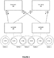
- Figure 3 shows an illustration of routing in a multi-tenant cluster environment, in which an embodiment of the present disclosure can be practiced. More specifically, Figure 3 elaborates on the issues of degraded load balancing and poor isolation.
- Figure 3 shows a 2-level fat-tree topology with four switches, root switches 325-326, and leaf switches 320-321, and six end nodes, nodes A-F, 301-306, in three overlapping partitions.
- Partition 1 comprises node B 302 and node C 303.
- Partition 2 comprises node A 301, node C 303, node D 304, and node F 306.
- partition 3 comprises node D 304 and node E 305.
- partitions 1 and 3 are entirely confined within the leaf switches 320 and 321 (i.e., single leaf switch partitions), respectively. Because of this, the communication between nodes in partitions 1 and 3 takes place through their corresponding leaf switches without moving traffic to the root switches, 325 or 326.
- the routes towards the nodes connected to the leaf switches 320 and 321 are assigned root switches so the inter-leaf switch flows can reach their destination. For load-balancing, the routes towards A and C are assigned root switch 325 (shown as link p on the figure), while the root switch 326 routes traffic towards node B (shown as link q on the figure).
- traffic towards nodes D and F, in interleaf switch partition 2 are routed via the root switch 325 (shown as link r on the figure), and the traffic towards node E is routed via root switch 326 (shown as link s on the figure).
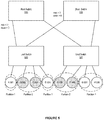
- Figure 4 shows an illustration of routing in a multi-tenant cluster environment, in which an embodiment of the present disclosure can be practiced. More specifically, Figure 4 elaborates on the issues associated with poor isolation within a fat-tree.
- Figure 4 shows a 2-level fat-tree topology with four switches, root switches 425-426, and leaf switches 420-421, and eight end nodes, nodes A-G, 401-408. As well, the end nodes are divided into two partitions. Partition 1 comprises node A 401, node B 402, node G 407, and node H 408. Partition 2 comprises node C 403, node D 404, node E 405, and node F406.
- Each of the partitions has two nodes connected to each of the two leaf switches.
- the fat-tree routing mechanism assigns downward ports on the root switches 425 and 426, as shown in the figure. Because of the nature of the fat-tree routing mechanism, each root switch routes traffic towards nodes belonging to both partitions, which provides for poor isolation, something that is not desired in a partitioned environment. For example, the traffic towards nodes A and C is routed on the shared link p. The sharing of intermediate links between nodes of different partitions can cause interference among them. Despite that the network has adequate resources at the root level to provide complete isolation among partitions, the fat-tree routing mechanism does not provide for the desired isolation.
- a pFTree mechanism can use partitioning information about the subnet to ensure that the nodes in a partition receive a predictable network performance that is unaffected by the workload running in other partitions.
- the pFTree can assign VLs to reduce the impact of interference.
- the pFTree mechanism can work recursively to set up LFTs on all relevant switches for the LIDs associated with each end node. This is shown in the below pseudo code (referred to herein as listing 1):
- the ROUTEDOWNGOINGBYASCENDINGTD() is exemplified in the below pseudo code (referred to herein as listing 2):
- the ROUTEUPGOINGBYDESCENDINGTD() is exemplified in the below pseudo code (referred to herein as listing 3):
- the ASSIGNVIRTUALLANESTD() is exemplified in the below pseudo code (referred to herein variously as listing 4):
- the mechanism can sort connected end nodes in a partitioning specific order (line 4 of above listing 1) (e.g., via each partition having a unique partitioning order number). This ordering can assist with ensuring that the nodes are routed according to their partitions, considering the available number of up-going ports at a leaf switch.
- the pFTree mechanism can then call a function, such as ROUTEDOWNGOINGBYASCENDINGTD (line 9 of above listing 1), and move up in the tree to select a port at the next level to route the LID, as shown in the listing 2.
- the port selection is based on a least number of already assigned routes. This can help ensure that the load is spread across the available paths. However, when several ports are available with the same load, the function can iterate through these least-loaded ports and select a port which is connected to a switch that is already marked with the partition key of the node being routed (lines 3-9 of listing 2). If no switch is marked (which can indicate that the first node for this partition is being routed), the system can default to the selection of the port with the highest globally unique identifier (GUID) (line 2 of listing 2). When a switch is selected the first time for a partition, it is marked in the downward direction with the partition key (line 11 of listing 2).
- GUID globally unique identifier
- the mechanism can assign upward ports for it on all the connected downward switches by descending down the tree calling (ROUTEUPGOINGBYDESCENDINGTD of listing 3).
- the selection of the up-going port can first be based on the load criterion and then on the partition marking of the remote switches, in the upward direction. The process can then be repeated by moving up to the next level in the tree until all LFTs are set.
- a switch can be marked with multiple partition keys.
- the pFTree mechanism can maintain a table for each switch, storing the count of routed nodes for each partition. This counter can be used to decide the selection of the port if several switches with marked partitions are available to route a node. The switch with the maximum number of already routed nodes for a partition can be selected.
- the mechanism can move on to check if some of the links are being used for flows towards nodes in different partitions. For those cases, the mechanism can assign VLs to the interfering partitions to provide isolation.
- VL assignment mechanism An example of a VL assignment mechanism is shown in Listing 4.
- the VL assignment mechanism can iterate through the partitions and check if any intermediate communication link used by the nodes in the partition shares an intermediate link with another partition that has not been assigned a separate VL. If such a situation is encountered, a new VL can be assigned.
- the pFTree routing mechanism can support two modes for the VL selection: a strict mode and a normal mode.
- the routing in the strict mode, if number of required VLs for pFTree routing exceeds the available VLs in the system, the routing can fail (line 10 of listing 4).
- the algorithm in the normal mode, can restart assigning VLs to the partitions from VL1 (line 8 of listing 4).
- an efficient partition-aware routing mechanism for IB based fat-tree networks (variously referred to as pFTree) is provided.
- the pFTree mechanism can provide network-wide isolation of partitions for fat-tree topologies.
- pFTree produces well balanced LFTs for the switches.
- pFTree can isolate partitions solely at the physical link level. For instance, if a fat-tree has two non-overlapping equal sized partitions, pFTree can divide the intermediate network links into two equally sized logical sub-networks based on the routing itself.
- pFTree can employ a complementary VL based isolation scheme that works in conjunction with the physical isolation.
- the pFTree routing mechanism aims to achieve two main objectives. Firstly, the mechanism can generate well-balanced LFTs for fat-tree topologies by distributing routes evenly across the links in the tree. Secondly, while maintaining routes on the links balanced, pFTree removes interference between paths belonging to different partitions. The pFTree can use partitioning information about the subnet and ensures that the nodes in a partition receive a predictable network performance, unaffected by the workload running in other partitions. If the topology does not have enough links available to provide partition isolation at each level (without compromising on the load-balancing), the pFTree can use VLs to reduce the impact of interference.
- the pFTree mechanism can work recursively to set up LFTs on all relevant switches for the LIDs associated with each end node. After filtering out single leaf switch partitions, for each leaf switch, the mechanism can sort connected end nodes in a partitioning specific order. This ordering ensures that the nodes are routed according to their partitions, considering the available number of up-going ports at a leaf switch.
- the port selection at each level can be based on the least number of already assigned routes to make sure that the load is spread across the available paths. However, when several ports are available with the same load, the function iterates through these least-loaded ports and selects a port which is connected to a switch that is already marked with the partition key of the node being routed.
- pFTree can fall to the default selection of the port with the highest globally unique identifier (GUID).
- GUID globally unique identifier
- the mechanism can help ensure that, given enough paths are available for balancing, the nodes belonging to one partition will be routed through the same switches and corresponding links.
- the mechanism can move on to check if some of the links are being used for flows towards nodes in different partitions. For those cases, the mechanism can assign VLs to the interfering partitions to provide isolation.
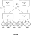
- FIGS 5-8 are illustrations of supporting partition-aware routing in a multi-tenant cluster environment, in accordance with an embodiment.
- the port selection mechanism in the pFTree routing is shown in Figures 5-8 by way of a simple section of an oversubscribed fat-tree network.
- Partition 1 comprises node A 501, node D 504, node G 507, and node H 508.
- Partition 2 comprises node B 502, node C 503, node E 505, and node F 506.
- the example section consists of two leaf switches (520 and 521), each connected to four end nodes and two switches at the next level above the leaf switches, i.e., root switches (525 and 526).
- the variables for down and max which represent a number of assigned routes in the downward direction, and maximum number of nodes that can be routed to ensure proper balancing on each link, respectively, are also indicated in the figure.
- leaf switch 520 the routing of the first two nodes, node A and node B, is shown in Figure 6 .
- the routing mechanism can select root switch 525 to route traffic towards node A and mark the switch with node A's partition key, shown as "(Partition 1)" in the figure.
- root switch 526 can be selected and marked with node B's partition key, shown as "(Partition 2)" in the figure.
- the variable down is also updated to count a single routed node on each of the two downward links.
- the switch which is already marked with the corresponding partition key, can be selected, as given in Figure 7 .
- the resultant routes flow towards nodes belonging to the first partition, i.e., nodes A and D, with the same link through root switch 525.
- the nodes of the second partition i.e., nodes B and C can be routed downwards through root switch 526. This separation of routes avoid interference between the traffic flows of the two partitions. Note that the number of nodes routed downwards on each links does not exceed the max variable, which means that the routing is still balanced.
- Figure 8 shows routing for the end nodes connected to the leaf switch 521.
- the corresponding switches can be selected to route each of the nodes, i.e., nodes E, F, G, and H.
- the final routing can isolate the two partitions by dividing the intermediate network links into two equal sized logical sub-networks based on the routing.
- the pFTree routing algorithm uses VLs to reduce inter-partition interference.
- VLs service level agreements
- different partitions may have different isolation needs depending on the corresponding SLAs (service level agreements) or QoS requirements.
- some of the partitions in a network may be running critical operations, and may require complete physical isolation in all cases.
- some partitions may have to share a VL with another partition, which may not be desirable for communication-intensive workloads.
- the pFTree algorithm described above is unable to specify the aforementioned partition-wise requirements in the routing, and all partitions are treated with equal priority assuming similar QoS requirements.
- Figure 9 is an illustration of supporting network isolation in a multi-tenant cluster environment, in accordance with an embodiment. More specifically, Figure 9 represents an example of a fat-tree network with nine nodes (i.e., nodes A-I, 901-909) in three different tenant partitions (shown by the varied shading). Nodes A 901 and E 905 belong to partition 1, nodes B 902, F 906, G 907, and I 909 belong to partition 2, and nodes C 903, D 904, and H 908 belong to partition 3.
- the fat tree network additionally contains root switches 925 and 926, as well as leaf switches 920, 921, and 922.
- partition 1 can have very high QoS requirements, and that it is critically important that the workload running in this partition is not affected by any inter-partition interference.
- the given fat-tree network has only two root switches, root switch 925 and root switch 926, while having three different tenant partitions, it is not possible to isolate these partitions solely at the physical level.
- the pFTree routing algorithm can proceed with isolating partitions using VLs. Also shown in the figure is the routing obtained using the default pFTree algorithm (above), using small node circles just below the switches to denote flows towards the destination nodes.
- the pFTree routing mechanism can be extended to include partition-wise and global isolation policies.
- the isolation policies can determine how the nodes in a partition are allowed to share network resources with nodes belonging to other partitions.
- the global policies can determine whether the routing will fail, or continue with best-effort isolation if all partition-wise isolation policies cannot be satisfied for a given network.
- each partition can be marked with one of the three partition-wise policy parameters.
- Marking a partition with a phy-isolation (also referred to herein as a strict parameter) can guarantee that the routing algorithm reserves network resources specifically for the partition, and no nodes in the partition will share any link with any other node in a different partition.
- Marking a partition with a parameter vlane-isolation (also referred to herein as a strict virtual lane parameter) allows the marked partition to share network resources with other partitions using a separate VL only.
- Marking a partition with a def-isolation (also referred to herein as a best effort parameter) scheme implements best-effort isolation for the marked partition.
- the policy parameters can also include global policy parameters.
- Global policy parameters, strict and best-effort can define whether the routing mechanism fails or falls back to the best-efforts routing when partition-wise policy parameters cannot be satisfied in a given subnet. For example, when a network does not have enough links or VLs for providing the desired isolation.
- the policy parameters can be provided to the routing mechanism using a partition configuration file.
- an extended pFTree routing mechanism (also referred to herein variously as "pFTree-Ext”) works in a similar fashion as the original pFTree (described above), by recursively traversing the fabric to set up LFTs in all switches for the LIDs associated with each end node.
- pFTree-Ext can also consider the defined global and partition-wise isolation policies when assigning routes.
- pseudo code of the pFTree-Ext (also referred to herein variously as listing 5) routing mechanism is shown below:
- the mechanism is deterministic and the routes are calculated backwards, starting at the destination nodes.
- the mechanism can first sort compute nodes in a partition specific order (line 3 of listing 5).
- the partition specific order can ensure faster execution of the mechanism, as once the nodes are ordered, they can be routed iteratively without maintaining maximum counters on each down-going and up-going port.
- ORDERCOMPUTENODES first sorts end nodes in the increasing order of their partition policy priority (line 4 of listing 6 (see below)). The nodes belonging to the partitions marked with phy-isolation parameter can be added first, while partitions with vlane-isolation can be added second.
- partition nodes with policy parameter value of def-isolation are added to the list of compute nodes.
- the mechanism uses partitioning information of the nodes to generate a routing order where nodes belonging to one partition tends to get indices suggesting same up-going links in the network on iterative routing. This is done by adding the number of available up-going ports to the index chosen to route the first node belonging to a partition, using a partition key table (lines 14-28 of listing 6). However, when such an index is already taken or the index is beyond the compute array bounds, the first free index can be chosen and marked with the partition key for later selections (line 24 of listing 6).
- Pseudo code for ORDERCOMPUTENODES (also referred to herein variously as listing 6) is shown here:
- the pFTree-Ext mechanism can call ROUTEDOWNGOINGBYASCENDING (line 9 of listing 5) and moves up in the tree to select a port at the next level to route the LID in the downward direction, as exemplified in the below pseudo code for ROUTEDOWNGOINGBYASCENDING (also referred to herein variously as listing 7):
- the port selection is first based on the least-loaded port list obtained from the sorted available up-going ports (line 1-2 of listing 7).
- the function iterates through these least-loaded ports and selects a port which is connected to a switch that is already marked with the partition key of the node being routed (lines 5-11 of listing 7). If no switch is found marked, the algorithm iterates through the up-going ports to find a suitable route for the LID.
- the up-going port list is sorted in the increasing order of the current load on the ports. For the ports with same load, sorting is done in decreasing order of their globally unique identifiers (GUIDs) in order to remain deterministic.
- GUIDs globally unique identifiers
- the function does not select a port which is already marked with a partition key with a higher isolation policy parameter than the routed node (line 16-17 of listing 7). Finally, when a port is selected, the corresponding switch is marked in the downward direction with the partition key (line 24 of listing 7).
- the pFTree-Ext mechanism assigns upward ports for it on all the connected downward switches by descending down the tree calling ROUTEUPGOINGBYDESCENDING (also referred to herein variously as listing 8).
- ROUTEUPGOINGBYDESCENDING also referred to herein variously as listing 8
- the selection of the up-going port is first based on the load criterion and then on the partition marking of the remote switches, in the upward direction this time. The process is then repeated by moving up to the next level in the tree until all LFTs are set.
- a switch can be marked with multiple partition keys.
- the pFTree-Ext mechanism maintains a table for each switch, storing the count of routed nodes for each partition. This counter is used to decide the selection of the port if several switches with marked partitions are available to route a node. The switch with the maximum number of already routed nodes for a partition is selected.
- the pFTree-Ext mechanism moves on to check if some of the links are being used for flows towards nodes in different partitions. For those cases, the pFTree-Ext mechanism can assign VLs to the interfering partitions to provide isolation.
- Pseudo code for VL assignment function, ASSIGNVIRTUALLANES is shown below in (herein referred to variously as listing 9):
- the virtual lane assignment function can iterate through all partitions and check if the partition is marked with the vl-isolation policy parameter, and if any intermediate communication links used by the nodes in the partition shares an intermediate link with another partition that has not been assigned a separate VL. If so, a new VL is assigned.
- the VL assignment function can also use global policy parameters with two modes: strict and best-effort. In the strict mode, if the number of required VLs for pFTree-Ext routing mechanism exceeds the number of available VLs in the system, the routing fails (line 10 of listing 9). In best-effort mode, the virtual lane assignment function can restart assigning VLs to the partitions from VL 1 (line 8 of listing 9).
- the pFTree-Ext routing mechanism can easily be modified to consider a particular group of VLs, rather than all available VLs. Similarly, to make it less likely for partitions with higher isolation policies to share VLs, once all available VLs are used, the VL list can be ordered by decreasing priority of assigned partitions for selection (instead of selecting VL 1 ). After the VLs are assigned, the pFTree-Ext routing algorithm validates whether all the partition-wise and global policies are met (line 13 of listing 5).
- the pFTree-Ext mechanism can incorporate isolation policies into a routing algorithm. Unlike pFTree, which for each leaf switch sorts end nodes in the partition-specific order before routing, the pFTree-Ext routing mechanism first sorts end nodes in the order of their partition priorities. The end nodes in the partitions marked with phy-isolation get the maximum priority. After that, the mechanism proceeds by sorting end nodes in partition specific order as earlier. The additional sorting is done upfront to ensure that the nodes with the highest partition priorities are routed first.
- the pFTree-Ext mechanism can further incorporate isolation policies into a routing algorithm by changing the way a port is selected for routing a new node. For example, to select a down-going port among several candidate ports, the pFTree-Ext, besides checking the current load on the port, removes any port-group where the corresponding switch has already been marked with the key of a partition with a higher priority than the partition of the node currently being routed.
- the pFTree-Ext routing mechanism can either fail or proceeds according to the global policy parameters.
- the original pFTree routing algorithm only considers the available VLs in that case.
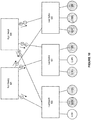
- Figure 10 is an illustration of supporting network isolation in a multi-tenant cluster environment, in accordance with an embodiment. More specifically, Figure 10 represents an example of a fat-tree network with nine nodes (i.e., nodes A-I, 901-909) in three different tenant partitions (shown by the varied shading). Nodes A 901 and E 905 belong to partition 1, nodes B 902, F 906, G 907, and I 909 belong to partition 2, and nodes C 903, D 904, and H 908 belong to partition 3.
- the fat tree network additionally contains root switches 925 and 926, as well as leaf switches 920, 921, and 922.
- Figure 10 represents a subnet routing using a pFTree-Ext mechanism where partition 1 (i.e., node A 901 and node E 905) has been marked with high priority, such as a phy-isolation, which can guarantee that the routing mechanism reserves network resources specifically for the partition, and no nodes in the partition will share any link with any other node in a different partition.
- the resultant routing is shown in Figure 10 . Because partition 1 has been marked with a high priority, such as phy-isolation, neither node of partition 1 (i.e., nodes A and E) share links with any other partition. However, as no such policy was applied to partition 2 and/or partition 3, these partitions share all down-going links from switch 926.
- a second extension of the pFTree routing mechanism can account for weight of traffic characteristics in a subnet.
- This can be referred to as weighted pFTree routing mechanism (pFTree-Wt).
- the pFTree-Wt is based on the notion of weights associated with each compute node. These weights are used to take known or learned traffic characteristics into account when calculating routes. Irrespective of the partitioning, the weight of a node reflects the degree of priority the flows towards a node receive when calculating routing tables. For example, a possible configuration could be to assign weights to the nodes in the range [1, 100] depending on how much traffic a node is known to receive in the network.
- the values in between, 1 ⁇ x ⁇ 100, can then reflect the proportion of traffic a node is expected to receive in the network.
- weights can be calculated using a port data counter based scheme. For example, in OFED (OpenFabrics Enterprise Distribution), a utility called ibdatacounts is provided for reading data counters. After setting up the network with equal initial weights for all nodes, new weights can be learned after a specified time period.
- OFED OpenFabrics Enterprise Distribution
- each compute node can be assigned a parameter, weight.
- the load on a port in the pFTree-Wt routing scheme is the accumulated weight of the compute nodes routed from that port in each direction.
- the nodes in one partition are also sorted by their weights before routing.
- pFTree-Wt updates the current load on the selected port by adding the weight of the corresponding compute node.
- an upward load is maintained on each port.
- the port selection criteria is similar to the pFTree routing, and considers the partitions of the node as well. However, unlike port counters, the port selection at each level in pFTree-Wt is based on the least accumulated weight on all the available ports. When several ports are available with the same load, the mechanism iterates over these least-loaded ports and selects a port which is connected to a switch that is already marked with the partition key of the node being routed. Once the routing tables are generated, the pFTree-Wt can run VL assignment to ensure that different VLs are assigned to nodes associated with different partitions sharing links in the network.
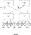
- Figure 11 shows an illustration of supporting weighted partition-aware routing in a multi-tenant cluster environment, in accordance with an embodiment. Specifically, Figure 11 shows a 2-level fat-tree topology with four switches, root switches 1125-1126, and leaf switches 1120-1121, and eight end nodes, nodes A-G, 1101-1108. As well, the end nodes are divided into two partitions. Partition 1 comprises node A 1101, node D 1104, node G 1107, and node H 1108. Partition 2 comprises node B 1102, node C 1103, node E 1105, and node F 1106.
- each node in Figure 11 has been assigned a weight.
- Node A 1101 has been assigned a weight of 100, while the remaining nodes have been assigned a weight of 1.
- the downward routing using pFTree-Wt to leaf switch 1120 is shown in Figure 11 .
- the node A has a weight equal to 100, it is assigned one of those links, switch 1125 ⁇ switch 1120, while the other three nodes share the other link, switch 1126 ⁇ switch 1120. This is because the sum of the weights of the other three nodes is only 3, which is lower than 100.
- the selected switches are marked with the partition keys, still the partitions cannot be isolated in the subnet due to the weighted partition-aware routing.
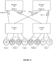
- Figure 12 shows an illustration of supporting weighted partition-aware routing in a multi-tenant cluster environment, in accordance with an embodiment. Specifically, Figure 12 shows a 2-level fat-tree topology with four switches, root switches 1125-1126, and leaf switches 1120-1121, and eight end nodes, nodes A-G, 1101-1108. As well, the end nodes are divided into two partitions. Partition 1 comprises node A 1101, node D 1104, node G 1107, and node H 1108. Partition 2 comprises node B 1102, node C 1103, node E 1105, and node F 1106.
- each node in Figure 12 has been assigned a weight.
- Node A 1101 has been assigned a weight of 100, while the remaining nodes have been assigned a weight of 1.
- the downward routing using pFTree-Wt to leaf switch 1121 is shown in Figure 12 .
- each node connected to leaf switch 1121 has an identical weight (i.e., 1). Because of this, the partitions can remain isolated on the links.
- Nodes G and H, belonging to the same partition can be routed through the link between switch 1125 ⁇ switch 1121 in the downward direction..
- Nodes E and F of partition 2 and having an equal weight, can be routed through the link between switch 1126 ⁇ switch 1121 in the downward direction.
- pFTree-Wt satisfies the weighted load balancing on the links, while keeping the partitions as isolated as possible. Note that the final routing, as shown in Figure 12 , has only one link shared by the nodes of the two partitions.
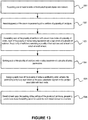
- Figure 13 is a flow chart of a method for supporting network isolation in a multi-tenant cluster environment, in accordance with an embodiment.
- the method can support one or more tenants within the multi-tenant cluster environment.
- the method can associate each of the one or more tenants with a partition of a plurality of partitions.
- the method can associate each of the plurality of partitions with one or more nodes of a plurality of nodes, each of the plurality of nodes being associated with a leaf switch of a plurality of switches, the plurality of switches comprising a plurality of leaf switches and at least one switch at another level.
- the method can mark each of the plurality of partitions with a policy parameter of a plurality of policy parameters.
- the method can assign each node of the plurality of nodes a partitioning order, wherein the partitioning order is at least based on policy parameter marked on the partition associated with each node.
- the method can generate one or more linear forwarding tables for use in the multi-tenant cluster environment.
- FIG 14 is a block diagram illustrating an exemplary computer system 1400 in which embodiments of the present invention may be implemented.
- the computer system 1400 is shown comprising hardware elements that may be electrically coupled via a bus 1490.
- the hardware elements may include one or more central processing units 1410, one or more input device(s) 1420 (e.g., a mouse, a keyboard, etc.), and one or more output device(s) 1430 (e.g., a display device, a printer, etc.).
- the computer system 1400 may also include one or more storage device(s) 1440.
- storage device(s) 1440 may be disk drives, optical storage devices, a solid-state storage device such as a random access memory (“RAM”) and/or a read-only memory (“ROM”), which can be programmable, flash-updateable and/or the like.
- RAM random access memory
- ROM read-only memory
- the storage device can include, but is not limited to, any type of disk including floppy disks, optical discs, DVD, CD-ROMs, microdrive, and magneto-optical disks, ROMs, RAMs, EPROMs, EEPROMs, DRAMs, VRAMs, flash memory devices, magnetic or optical cards, nanosystems (including molecular memory ICs), or any type of media or device suitable for storing instructions and/or data.
- any type of disk including floppy disks, optical discs, DVD, CD-ROMs, microdrive, and magneto-optical disks, ROMs, RAMs, EPROMs, EEPROMs, DRAMs, VRAMs, flash memory devices, magnetic or optical cards, nanosystems (including molecular memory ICs), or any type of media or device suitable for storing instructions and/or data.
- the computer system 1400 may additionally include a computer-readable storage media reader 1450, a communications system 14140 (e.g., a modem, a network card (wireless or wired), an infra-red communication device, BluetoothTM device, cellular communication device, etc.), and working memory 1480, which may include RAM and ROM devices as described above.
- the computer system 1400 may also include a processing acceleration unit 1470, which can include a digital signal processor, a special-purpose processor and/or the like.
- the computer-readable storage media reader 1450 can further be connected to a computer-readable storage medium, together (and, optionally, in combination with storage device(s) 1440) comprehensively representing remote, local, fixed, and/or removable storage devices plus storage media for temporarily and/or more permanently containing computer-readable information.
- a computer-readable storage medium Stored on any one of the machine readable medium (media), features of the present invention can be incorporated in software and/or firmware for controlling the hardware of the computer system, and for enabling the computer system to interact with other mechanism utilizing the results of the present invention.
- Such software or firmware may include, but is not limited to, application code, device drivers, operating systems and execution environments/containers.
- the communications system 1460 may permit data to be exchanged with a network, system, computer and/or other component described above.
- the computer system 1400 may also comprise software elements, shown as being currently located within a working memory 1480, including an operating system 1488 and/or other code 1484. It should be appreciated that alternate embodiments of a computer system 1400 may have numerous variations from that described above. For example, customized hardware might also be used and/or particular elements might be implemented in hardware, software (including portable software, such as applets), or both. Furthermore, connection to other computing devices such as network input/output and data acquisition devices may also occur.
- Software of computer system 1400 may include code 1484 for implementing any or all of the functions of the various elements of the architecture as described herein.
- software stored on and/or executed by a computer system such as system 1400, can provide the functionality and/or other components of the invention such as those discussed above. Methods implementable by software on some of these components have been discussed above in more detail.
Landscapes
- Engineering & Computer Science (AREA)
- Theoretical Computer Science (AREA)
- Computer Networks & Wireless Communication (AREA)
- Signal Processing (AREA)
- Software Systems (AREA)
- General Physics & Mathematics (AREA)
- General Engineering & Computer Science (AREA)
- Physics & Mathematics (AREA)
- Databases & Information Systems (AREA)
- Radar, Positioning & Navigation (AREA)
- Remote Sensing (AREA)
- Data Mining & Analysis (AREA)
- Data Exchanges In Wide-Area Networks (AREA)
Applications Claiming Priority (5)
| Application Number | Priority Date | Filing Date | Title |
|---|---|---|---|
| US201562240986P | 2015-10-13 | 2015-10-13 | |
| US201562242211P | 2015-10-15 | 2015-10-15 | |
| US15/182,383 US10187310B2 (en) | 2015-10-13 | 2016-06-14 | System and method for efficient network isolation and load balancing in a multi-tenant cluster environment |
| US15/182,397 US10033647B2 (en) | 2015-10-13 | 2016-06-14 | System and method for efficient network isolation and load balancing in a multi-tenant cluster environment |
| PCT/US2016/050992 WO2017065905A1 (en) | 2015-10-13 | 2016-09-09 | System and method for efficient network isolation and load balancing in a multi-tenant cluster environment |
Publications (2)
| Publication Number | Publication Date |
|---|---|
| EP3362894A1 EP3362894A1 (en) | 2018-08-22 |
| EP3362894B1 true EP3362894B1 (en) | 2020-12-09 |
Family
ID=58499143
Family Applications (1)
| Application Number | Title | Priority Date | Filing Date |
|---|---|---|---|
| EP16770834.6A Active EP3362894B1 (en) | 2015-10-13 | 2016-09-09 | System and method for efficient network isolation and load balancing in a multi-tenant cluster environment |
Country Status (5)
| Country | Link |
|---|---|
| US (9) | US10033647B2 (enExample) |
| EP (1) | EP3362894B1 (enExample) |
| JP (1) | JP6752815B2 (enExample) |
| CN (2) | CN112260970B (enExample) |
| WO (1) | WO2017065905A1 (enExample) |
Families Citing this family (24)
| Publication number | Priority date | Publication date | Assignee | Title |
|---|---|---|---|---|
| US8776207B2 (en) * | 2011-02-16 | 2014-07-08 | Fortinet, Inc. | Load balancing in a network with session information |
| US10198288B2 (en) | 2014-10-30 | 2019-02-05 | Oracle International Corporation | System and method for providing a dynamic cloud with subnet administration (SA) query caching |
| CN107113233B (zh) * | 2014-10-31 | 2020-06-23 | 甲骨文国际公司 | 用于支持多租户集群环境中的分区感知路由的系统和方法 |
| US10033647B2 (en) * | 2015-10-13 | 2018-07-24 | Oracle International Corporation | System and method for efficient network isolation and load balancing in a multi-tenant cluster environment |
| US11271870B2 (en) * | 2016-01-27 | 2022-03-08 | Oracle International Corporation | System and method for supporting scalable bit map based P_Key table in a high performance computing environment |
| US10594627B2 (en) | 2016-01-27 | 2020-03-17 | Oracle International Corporation | System and method for supporting scalable representation of switch port status in a high performance computing environment |
| US10374926B2 (en) | 2016-01-28 | 2019-08-06 | Oracle International Corporation | System and method for monitoring logical network traffic flows using a ternary content addressable memory in a high performance computing environment |
| US10536334B2 (en) | 2016-01-28 | 2020-01-14 | Oracle International Corporation | System and method for supporting subnet number aliasing in a high performance computing environment |
| EP3258382B1 (en) * | 2016-06-14 | 2021-08-11 | Arm Ltd | A storage controller |
| WO2018039061A1 (en) * | 2016-08-23 | 2018-03-01 | Oracle International Corporation | System and method for supporting fast hybrid reconfiguration in a high performance computing environment |
| US10652102B2 (en) * | 2017-06-19 | 2020-05-12 | Cisco Technology, Inc. | Network node memory utilization analysis |
| US10320654B2 (en) * | 2017-07-12 | 2019-06-11 | International Business Machines Corporation | Method for remote node discovery and communication channel validation and connection |
| US10574755B2 (en) * | 2018-03-28 | 2020-02-25 | Wipro Limited | Method and high performance computing (HPC) switch for optimizing distribution of data packets |
| CN109547470B (zh) * | 2018-12-20 | 2020-10-27 | 北京交通大学 | 保护网络空间安全的电子隔离墙方法、装置及系统 |
| CN110336759B (zh) * | 2018-12-26 | 2022-04-26 | 锐捷网络股份有限公司 | 基于rdma的协议报文转发方法及装置 |
| CN111526113B (zh) | 2019-02-02 | 2023-05-30 | 中兴通讯股份有限公司 | 协议处理方法及装置、存储介质 |
| CN110381093B (zh) * | 2019-09-03 | 2022-07-19 | 北京旷视科技有限公司 | 数据协议转换的方法、装置、数据传输的系统及电子设备 |
| US11700206B2 (en) | 2019-11-19 | 2023-07-11 | Oracle International Corporation | System and method for supporting RDMA bandwidth restrictions in a private fabric in a high performance computing environment |
| CN111181866B (zh) * | 2019-12-21 | 2023-06-30 | 武汉迈威通信股份有限公司 | 一种基于端口隔离的端口汇聚方法及系统 |
| CN113190167A (zh) * | 2020-01-14 | 2021-07-30 | 伊姆西Ip控股有限责任公司 | 用于管理计算设备的方法、电子设备和计算机存储介质 |
| CN112866367A (zh) * | 2021-01-12 | 2021-05-28 | 优刻得科技股份有限公司 | 基于可编程交换机的路由系统 |
| US11483234B2 (en) * | 2021-03-03 | 2022-10-25 | Cisco Technology, Inc. | Predictive routing-based policy adjustments in software-defined networks |
| US12028663B2 (en) * | 2021-07-21 | 2024-07-02 | Infinera Corporation | Data center interconnect |
| US20230094159A1 (en) * | 2021-09-28 | 2023-03-30 | Oracle International Corporation | System and method for dynamically partitioned multi-tenant namespaces |
Family Cites Families (85)
| Publication number | Priority date | Publication date | Assignee | Title |
|---|---|---|---|---|
| DE4430993C1 (de) | 1994-08-31 | 1995-10-26 | Siemens Ag | Verfahren zur adaptiven Wegesuche in einem Kommunikationsnetz |
| US7117242B2 (en) * | 2001-06-20 | 2006-10-03 | Hewlett-Packard Development Company, L.P. | System and method for workload-aware request distribution in cluster-based network servers |
| US7286544B2 (en) * | 2002-07-25 | 2007-10-23 | Brocade Communications Systems, Inc. | Virtualized multiport switch |
| US7146499B2 (en) * | 2002-09-30 | 2006-12-05 | International Business Machines Corporation | Security system for replicated storage devices on computer networks |
| US20070067366A1 (en) * | 2003-10-08 | 2007-03-22 | Landis John A | Scalable partition memory mapping system |
| WO2005036806A2 (en) * | 2003-10-08 | 2005-04-21 | Unisys Corporation | Scalable partition memory mapping system |
| US20070061441A1 (en) * | 2003-10-08 | 2007-03-15 | Landis John A | Para-virtualized computer system with I/0 server partitions that map physical host hardware for access by guest partitions |
| US7360030B1 (en) * | 2004-06-01 | 2008-04-15 | Sanbolic, Inc. | Methods and apparatus facilitating volume management |
| US7953843B2 (en) * | 2004-06-14 | 2011-05-31 | Hewlett-Packard Development Company, L.P. | System and method for evaluating a heterogeneous cluster for supporting expected workload in compliance with at least one service parameter |
| US8364891B2 (en) | 2006-04-04 | 2013-01-29 | Permabit Technology Corporation | Storage assignment technique for scalable and fault tolerant storage system |
| US8089904B2 (en) * | 2006-08-01 | 2012-01-03 | Opnet Technologies, Inc. | Link inference in large networks based on incomplete data |
| US8670352B2 (en) * | 2006-08-01 | 2014-03-11 | Riverbed Technology, Inc. | Link inference in large networks based on incomplete data |
| US7661027B2 (en) * | 2006-10-10 | 2010-02-09 | Bea Systems, Inc. | SIP server architecture fault tolerance and failover |
| US8156107B2 (en) * | 2007-02-02 | 2012-04-10 | Teradata Us, Inc. | System and method for join-partitioning for local computability of query over shared-nothing clusters |
| US8200738B2 (en) * | 2007-09-30 | 2012-06-12 | Oracle America, Inc. | Virtual cluster based upon operating system virtualization |
| US9071608B2 (en) * | 2008-04-28 | 2015-06-30 | International Business Machines Corporation | Method and apparatus for load balancing in network based telephony application |
| US8458717B1 (en) * | 2008-09-23 | 2013-06-04 | Gogrid, LLC | System and method for automated criteria based deployment of virtual machines across a grid of hosting resources |
| US20130129068A1 (en) * | 2009-03-02 | 2013-05-23 | Twilio, Inc. | Method and system for a multitenancy telephone network |
| US8108612B2 (en) * | 2009-05-15 | 2012-01-31 | Microsoft Corporation | Location updates for a distributed data store |
| EP2552604A1 (en) | 2010-03-30 | 2013-02-06 | Merck Patent GmbH | Method for producing multicoloured coatings |
| US8385356B2 (en) * | 2010-03-31 | 2013-02-26 | International Business Machines Corporation | Data frame forwarding using a multitiered distributed virtual bridge hierarchy |
| EP2564561B1 (en) * | 2010-04-30 | 2019-07-31 | Hewlett-Packard Enterprise Development LP | Method for routing data packets in a fat tree network |
| JP5476261B2 (ja) | 2010-09-14 | 2014-04-23 | 株式会社日立製作所 | マルチテナント型情報処理システム、管理サーバ及び構成管理方法 |
| US8762323B2 (en) * | 2011-02-10 | 2014-06-24 | Nec Laboratories America, Inc. | Replica based load balancing in multitenant databases |
| US9654601B2 (en) * | 2011-03-14 | 2017-05-16 | Verizon Digital Media Services Inc. | Network connection hand-off and hand-back |
| US8793684B2 (en) * | 2011-03-16 | 2014-07-29 | International Business Machines Corporation | Optimized deployment and replication of virtual machines |
| US9900293B2 (en) | 2011-06-03 | 2018-02-20 | Oracle International Corporation | System and method for supporting automatic disabling of degraded links in an infiniband (IB) network |
| US8572091B1 (en) * | 2011-06-27 | 2013-10-29 | Amazon Technologies, Inc. | System and method for partitioning and indexing table data using a composite primary key |
| US8595267B2 (en) * | 2011-06-27 | 2013-11-26 | Amazon Technologies, Inc. | System and method for implementing a scalable data storage service |
| US8601000B1 (en) * | 2011-06-27 | 2013-12-03 | Amazon Technologies, Inc. | System and method for conditionally updating an item with attribute granularity |
| US8732517B1 (en) * | 2011-06-30 | 2014-05-20 | Amazon Technologies, Inc. | System and method for performing replica copying using a physical copy mechanism |
| US9052831B1 (en) * | 2011-06-30 | 2015-06-09 | Amazon Technologies, Inc. | System and method for performing live partitioning in a data store |
| US8671407B2 (en) * | 2011-07-06 | 2014-03-11 | Microsoft Corporation | Offering network performance guarantees in multi-tenant datacenters |
| TWI583151B (zh) * | 2011-08-04 | 2017-05-11 | 中界雲端公司 | 實施及管理虛擬網路的系統與方法 |
| US8584136B2 (en) * | 2011-08-15 | 2013-11-12 | Sap Ag | Context-aware request dispatching in clustered environments |
| US10200493B2 (en) | 2011-10-17 | 2019-02-05 | Microsoft Technology Licensing, Llc | High-density multi-tenant distributed cache as a service |
| US9014201B2 (en) | 2011-11-09 | 2015-04-21 | Oracle International Corporation | System and method for providing deadlock free routing between switches in a fat-tree topology |
| US8879396B2 (en) * | 2011-11-15 | 2014-11-04 | Oracle International Corporation | System and method for using dynamic allocation of virtual lanes to alleviate congestion in a fat-tree topology |
| US9325619B2 (en) * | 2011-11-15 | 2016-04-26 | Oracle International Corporation | System and method for using virtual lanes to alleviate congestion in a fat-tree topology |
| WO2013071330A1 (en) * | 2011-11-16 | 2013-05-23 | Cheok Francis | Smart system and method for dynamic strategies in statistical arbitrage trading |
| US8886781B2 (en) * | 2011-12-13 | 2014-11-11 | Microsoft Corporation | Load balancing in cluster storage systems |
| US9033781B2 (en) | 2011-12-30 | 2015-05-19 | Mindforce Consulting, Llc | Designing a real sports companion match-play crowdsourcing electronic game |
| US9167049B2 (en) * | 2012-02-02 | 2015-10-20 | Comcast Cable Communications, Llc | Content distribution network supporting popularity-based caching |
| EP2784675B1 (en) * | 2012-02-09 | 2016-12-28 | Huawei Technologies Co., Ltd. | Method, device and system for data reconstruction |
| US8751650B2 (en) * | 2012-05-10 | 2014-06-10 | Cisco Technology, Inc. | Method and apparatus for supporting access control lists in a multi-tenant environment |
| US9584605B2 (en) * | 2012-06-04 | 2017-02-28 | Oracle International Corporation | System and method for preventing denial of service (DOS) attack on subnet administrator (SA) access in an engineered system for middleware and application execution |
| US8805990B2 (en) * | 2012-07-12 | 2014-08-12 | Microsoft Corporation | Load balancing for single-address tenants |
| CN103227843B (zh) * | 2012-08-31 | 2016-05-04 | 杭州华三通信技术有限公司 | 一种物理链路地址管理方法及装置 |
| US10460270B2 (en) | 2012-09-12 | 2019-10-29 | Salesforce.Com, Inc. | Systems, methods, and apparatuses for implementing cross-organizational processing of business intelligence metrics |
| US20140096152A1 (en) * | 2012-09-28 | 2014-04-03 | Ron Ferens | Timing advertisement breaks based on viewer attention level |
| US9356886B2 (en) * | 2012-10-05 | 2016-05-31 | Cisco Technology, Inc. | Techniques for scalable and foolproof virtual machine move handling with virtual port channels |
| US8862772B2 (en) * | 2012-10-09 | 2014-10-14 | Cisco Technology, Inc. | System and method for implementing a multilevel data center fabric in a network environment |
| US9276866B2 (en) * | 2012-11-30 | 2016-03-01 | Microsoft Technology Licensing, Llc | Tuning congestion notification for data center networks |
| TW201438471A (zh) * | 2013-03-20 | 2014-10-01 | Hon Hai Prec Ind Co Ltd | 資料傳輸方法 |
| US9330119B2 (en) | 2013-04-11 | 2016-05-03 | Oracle International Corporation | Knowledge intensive data management system for business process and case management |
| CN103269282A (zh) | 2013-04-25 | 2013-08-28 | 杭州华三通信技术有限公司 | 网络配置自动部署方法和装置 |
| US9325636B2 (en) * | 2013-06-14 | 2016-04-26 | Cisco Technology, Inc. | Scaling interconnected IP fabric data centers |
| US9055095B2 (en) * | 2013-06-14 | 2015-06-09 | Microsoft Technology Licensing, Llc | DOS detection and mitigation in a load balancer |
| US9392079B2 (en) | 2013-07-19 | 2016-07-12 | International Business Machines Corporation | Directory service discovery and/or learning |
| KR20160042087A (ko) * | 2013-08-09 | 2016-04-18 | 휴렛 팩커드 엔터프라이즈 디벨롭먼트 엘피 | 스위치 어셈블리 |
| US9973425B2 (en) * | 2013-08-27 | 2018-05-15 | Oracle International Corporation | System and method for providing a data service in an engineered system for middleware and application execution |
| US9203765B2 (en) * | 2013-08-30 | 2015-12-01 | Cisco Technology, Inc. | Flow based network service insertion using a service chain identifier |
| US9264351B2 (en) | 2013-09-07 | 2016-02-16 | Cisco Technology, Inc. | System and method for utilization of a segmentation identification to support transmission of data to a destination node |
| US9621511B2 (en) * | 2013-09-10 | 2017-04-11 | Arista Networks, Inc. | Method and system for auto-provisioning network devices in a data center using network device location in network topology |
| US9405568B2 (en) * | 2013-09-13 | 2016-08-02 | Microsoft Technology Licensing, Llc | Multi-tenant network stack |
| US9917797B2 (en) * | 2013-10-01 | 2018-03-13 | Arista Networks, Inc. | Method and system for managing switch workloads in a cluster |
| US9876711B2 (en) * | 2013-11-05 | 2018-01-23 | Cisco Technology, Inc. | Source address translation in overlay networks |
| US9397946B1 (en) * | 2013-11-05 | 2016-07-19 | Cisco Technology, Inc. | Forwarding to clusters of service nodes |
| CN105981330A (zh) * | 2013-11-06 | 2016-09-28 | 瑞典爱立信有限公司 | 实现网络虚拟化覆盖架构中的负载均衡 |
| US9602616B2 (en) * | 2013-11-06 | 2017-03-21 | Neustar, Inc. | System and method for facilitating routing |
| CN103647668A (zh) * | 2013-12-16 | 2014-03-19 | 上海证券交易所 | 一种高可用集群内主机群体决策系统及切换方法 |
| US9225597B2 (en) * | 2014-03-14 | 2015-12-29 | Nicira, Inc. | Managed gateways peering with external router to attract ingress packets |
| CN104954265B (zh) | 2014-03-25 | 2018-06-15 | 华为技术有限公司 | 发送组播报文的方法及交换机 |
| JP6387777B2 (ja) * | 2014-06-13 | 2018-09-12 | 富士通株式会社 | 評価プログラム、評価方法、および評価装置 |
| CN105207798B (zh) * | 2014-06-26 | 2020-03-13 | 中兴通讯股份有限公司 | 软件定义网络中的业务编排方法及装置 |
| US9401858B2 (en) * | 2014-06-30 | 2016-07-26 | Cisco Technology, Inc. | Loop avoidance during network convergence in switched networks |
| US10135737B2 (en) * | 2014-09-30 | 2018-11-20 | Nicira, Inc. | Distributed load balancing systems |
| US10225137B2 (en) | 2014-09-30 | 2019-03-05 | Nicira, Inc. | Service node selection by an inline service switch |
| CN107113233B (zh) * | 2014-10-31 | 2020-06-23 | 甲骨文国际公司 | 用于支持多租户集群环境中的分区感知路由的系统和方法 |
| CN104394130B (zh) * | 2014-11-12 | 2017-07-25 | 国云科技股份有限公司 | 一种多租户虚拟网络隔离方法 |
| US9628334B2 (en) * | 2014-12-19 | 2017-04-18 | Cisco Technology, Inc. | VLAN tagging in a virtual environment |
| US10222986B2 (en) * | 2015-05-15 | 2019-03-05 | Cisco Technology, Inc. | Tenant-level sharding of disks with tenant-specific storage modules to enable policies per tenant in a distributed storage system |
| US9634893B2 (en) * | 2015-07-21 | 2017-04-25 | Cisco Technology, Inc. | Auto-provisioning edge devices in a communication network using control plane communications |
| US9871731B2 (en) * | 2015-09-30 | 2018-01-16 | Microsoft Technology Licensing, Llc | Data plane manipulation in a load balancer |
| US10033647B2 (en) * | 2015-10-13 | 2018-07-24 | Oracle International Corporation | System and method for efficient network isolation and load balancing in a multi-tenant cluster environment |
-
2016
- 2016-06-14 US US15/182,397 patent/US10033647B2/en active Active
- 2016-06-14 US US15/182,383 patent/US10187310B2/en active Active
- 2016-09-09 EP EP16770834.6A patent/EP3362894B1/en active Active
- 2016-09-09 JP JP2017554456A patent/JP6752815B2/ja active Active
- 2016-09-09 CN CN202011123283.0A patent/CN112260970B/zh active Active
- 2016-09-09 WO PCT/US2016/050992 patent/WO2017065905A1/en not_active Ceased
- 2016-09-09 CN CN201680024094.3A patent/CN107533486B/zh active Active
-
2018
- 2018-07-17 US US16/037,955 patent/US10673762B2/en active Active
- 2018-12-20 US US16/227,536 patent/US10616117B2/en active Active
-
2020
- 2020-02-20 US US16/796,627 patent/US11356370B2/en active Active
- 2020-04-29 US US16/862,101 patent/US11102128B2/en active Active
-
2021
- 2021-08-23 US US17/409,553 patent/US11677667B2/en active Active
-
2023
- 2023-05-26 US US18/202,822 patent/US12149448B2/en active Active
-
2024
- 2024-10-30 US US18/932,311 patent/US20250055798A1/en active Pending
Non-Patent Citations (1)
| Title |
|---|
| None * |
Also Published As
| Publication number | Publication date |
|---|---|
| JP2018537004A (ja) | 2018-12-13 |
| US10033647B2 (en) | 2018-07-24 |
| US10187310B2 (en) | 2019-01-22 |
| CN112260970A (zh) | 2021-01-22 |
| CN107533486A (zh) | 2018-01-02 |
| CN112260970B (zh) | 2022-09-06 |
| US11677667B2 (en) | 2023-06-13 |
| US11356370B2 (en) | 2022-06-07 |
| US11102128B2 (en) | 2021-08-24 |
| US20220109631A1 (en) | 2022-04-07 |
| WO2017065905A1 (en) | 2017-04-20 |
| US10673762B2 (en) | 2020-06-02 |
| US12149448B2 (en) | 2024-11-19 |
| US20170104817A1 (en) | 2017-04-13 |
| US20230308393A1 (en) | 2023-09-28 |
| EP3362894A1 (en) | 2018-08-22 |
| JP6752815B2 (ja) | 2020-09-09 |
| US20190149473A1 (en) | 2019-05-16 |
| US20180343202A1 (en) | 2018-11-29 |
| US20200259749A1 (en) | 2020-08-13 |
| CN107533486B (zh) | 2020-11-10 |
| US20250055798A1 (en) | 2025-02-13 |
| US10616117B2 (en) | 2020-04-07 |
| US20200195559A1 (en) | 2020-06-18 |
| US20170104682A1 (en) | 2017-04-13 |
Similar Documents
| Publication | Publication Date | Title |
|---|---|---|
| US12149448B2 (en) | System and method for efficient network isolation and load balancing in a multi-tenant cluster environment | |
| EP3213471B1 (en) | System and method for supporting partition-aware routing in a multi-tenant cluster environment | |
| US11716293B2 (en) | System and method for supporting efficient load-balancing in a high performance computing (HPC) environment | |
| Zahid et al. | Efficient network isolation and load balancing in multi-tenant HPC clusters |
Legal Events
| Date | Code | Title | Description |
|---|---|---|---|
| STAA | Information on the status of an ep patent application or granted ep patent |
Free format text: STATUS: THE INTERNATIONAL PUBLICATION HAS BEEN MADE |
|
| PUAI | Public reference made under article 153(3) epc to a published international application that has entered the european phase |
Free format text: ORIGINAL CODE: 0009012 |
|
| STAA | Information on the status of an ep patent application or granted ep patent |
Free format text: STATUS: REQUEST FOR EXAMINATION WAS MADE |
|
| 17P | Request for examination filed |
Effective date: 20180514 |
|
| AK | Designated contracting states |
Kind code of ref document: A1 Designated state(s): AL AT BE BG CH CY CZ DE DK EE ES FI FR GB GR HR HU IE IS IT LI LT LU LV MC MK MT NL NO PL PT RO RS SE SI SK SM TR |
|
| AX | Request for extension of the european patent |
Extension state: BA ME |
|
| DAV | Request for validation of the european patent (deleted) | ||
| DAX | Request for extension of the european patent (deleted) | ||
| GRAP | Despatch of communication of intention to grant a patent |
Free format text: ORIGINAL CODE: EPIDOSNIGR1 |
|
| STAA | Information on the status of an ep patent application or granted ep patent |
Free format text: STATUS: GRANT OF PATENT IS INTENDED |
|
| INTG | Intention to grant announced |
Effective date: 20200225 |
|
| GRAJ | Information related to disapproval of communication of intention to grant by the applicant or resumption of examination proceedings by the epo deleted |
Free format text: ORIGINAL CODE: EPIDOSDIGR1 |
|
| STAA | Information on the status of an ep patent application or granted ep patent |
Free format text: STATUS: REQUEST FOR EXAMINATION WAS MADE |
|
| GRAP | Despatch of communication of intention to grant a patent |
Free format text: ORIGINAL CODE: EPIDOSNIGR1 |
|
| STAA | Information on the status of an ep patent application or granted ep patent |
Free format text: STATUS: GRANT OF PATENT IS INTENDED |
|
| INTC | Intention to grant announced (deleted) | ||
| INTG | Intention to grant announced |
Effective date: 20200709 |
|
| GRAS | Grant fee paid |
Free format text: ORIGINAL CODE: EPIDOSNIGR3 |
|
| GRAA | (expected) grant |
Free format text: ORIGINAL CODE: 0009210 |
|
| STAA | Information on the status of an ep patent application or granted ep patent |
Free format text: STATUS: THE PATENT HAS BEEN GRANTED |
|
| AK | Designated contracting states |
Kind code of ref document: B1 Designated state(s): AL AT BE BG CH CY CZ DE DK EE ES FI FR GB GR HR HU IE IS IT LI LT LU LV MC MK MT NL NO PL PT RO RS SE SI SK SM TR |
|
| REG | Reference to a national code |
Ref country code: GB Ref legal event code: FG4D |
|
| REG | Reference to a national code |
Ref country code: AT Ref legal event code: REF Ref document number: 1344111 Country of ref document: AT Kind code of ref document: T Effective date: 20201215 Ref country code: CH Ref legal event code: EP |
|
| REG | Reference to a national code |
Ref country code: DE Ref legal event code: R096 Ref document number: 602016049467 Country of ref document: DE |
|
| REG | Reference to a national code |
Ref country code: IE Ref legal event code: FG4D |
|
| PG25 | Lapsed in a contracting state [announced via postgrant information from national office to epo] |
Ref country code: NO Free format text: LAPSE BECAUSE OF FAILURE TO SUBMIT A TRANSLATION OF THE DESCRIPTION OR TO PAY THE FEE WITHIN THE PRESCRIBED TIME-LIMIT Effective date: 20210309 Ref country code: RS Free format text: LAPSE BECAUSE OF FAILURE TO SUBMIT A TRANSLATION OF THE DESCRIPTION OR TO PAY THE FEE WITHIN THE PRESCRIBED TIME-LIMIT Effective date: 20201209 Ref country code: FI Free format text: LAPSE BECAUSE OF FAILURE TO SUBMIT A TRANSLATION OF THE DESCRIPTION OR TO PAY THE FEE WITHIN THE PRESCRIBED TIME-LIMIT Effective date: 20201209 Ref country code: GR Free format text: LAPSE BECAUSE OF FAILURE TO SUBMIT A TRANSLATION OF THE DESCRIPTION OR TO PAY THE FEE WITHIN THE PRESCRIBED TIME-LIMIT Effective date: 20210310 |
|
| REG | Reference to a national code |
Ref country code: AT Ref legal event code: MK05 Ref document number: 1344111 Country of ref document: AT Kind code of ref document: T Effective date: 20201209 |
|
| PG25 | Lapsed in a contracting state [announced via postgrant information from national office to epo] |
Ref country code: SE Free format text: LAPSE BECAUSE OF FAILURE TO SUBMIT A TRANSLATION OF THE DESCRIPTION OR TO PAY THE FEE WITHIN THE PRESCRIBED TIME-LIMIT Effective date: 20201209 Ref country code: BG Free format text: LAPSE BECAUSE OF FAILURE TO SUBMIT A TRANSLATION OF THE DESCRIPTION OR TO PAY THE FEE WITHIN THE PRESCRIBED TIME-LIMIT Effective date: 20210309 Ref country code: LV Free format text: LAPSE BECAUSE OF FAILURE TO SUBMIT A TRANSLATION OF THE DESCRIPTION OR TO PAY THE FEE WITHIN THE PRESCRIBED TIME-LIMIT Effective date: 20201209 |
|
| REG | Reference to a national code |
Ref country code: NL Ref legal event code: MP Effective date: 20201209 |
|
| PG25 | Lapsed in a contracting state [announced via postgrant information from national office to epo] |
Ref country code: HR Free format text: LAPSE BECAUSE OF FAILURE TO SUBMIT A TRANSLATION OF THE DESCRIPTION OR TO PAY THE FEE WITHIN THE PRESCRIBED TIME-LIMIT Effective date: 20201209 Ref country code: NL Free format text: LAPSE BECAUSE OF FAILURE TO SUBMIT A TRANSLATION OF THE DESCRIPTION OR TO PAY THE FEE WITHIN THE PRESCRIBED TIME-LIMIT Effective date: 20201209 |
|
| REG | Reference to a national code |
Ref country code: LT Ref legal event code: MG9D |
|
| PG25 | Lapsed in a contracting state [announced via postgrant information from national office to epo] |
Ref country code: PT Free format text: LAPSE BECAUSE OF FAILURE TO SUBMIT A TRANSLATION OF THE DESCRIPTION OR TO PAY THE FEE WITHIN THE PRESCRIBED TIME-LIMIT Effective date: 20210409 Ref country code: RO Free format text: LAPSE BECAUSE OF FAILURE TO SUBMIT A TRANSLATION OF THE DESCRIPTION OR TO PAY THE FEE WITHIN THE PRESCRIBED TIME-LIMIT Effective date: 20201209 Ref country code: SK Free format text: LAPSE BECAUSE OF FAILURE TO SUBMIT A TRANSLATION OF THE DESCRIPTION OR TO PAY THE FEE WITHIN THE PRESCRIBED TIME-LIMIT Effective date: 20201209 Ref country code: SM Free format text: LAPSE BECAUSE OF FAILURE TO SUBMIT A TRANSLATION OF THE DESCRIPTION OR TO PAY THE FEE WITHIN THE PRESCRIBED TIME-LIMIT Effective date: 20201209 Ref country code: LT Free format text: LAPSE BECAUSE OF FAILURE TO SUBMIT A TRANSLATION OF THE DESCRIPTION OR TO PAY THE FEE WITHIN THE PRESCRIBED TIME-LIMIT Effective date: 20201209 Ref country code: CZ Free format text: LAPSE BECAUSE OF FAILURE TO SUBMIT A TRANSLATION OF THE DESCRIPTION OR TO PAY THE FEE WITHIN THE PRESCRIBED TIME-LIMIT Effective date: 20201209 Ref country code: EE Free format text: LAPSE BECAUSE OF FAILURE TO SUBMIT A TRANSLATION OF THE DESCRIPTION OR TO PAY THE FEE WITHIN THE PRESCRIBED TIME-LIMIT Effective date: 20201209 |
|
| PG25 | Lapsed in a contracting state [announced via postgrant information from national office to epo] |
Ref country code: PL Free format text: LAPSE BECAUSE OF FAILURE TO SUBMIT A TRANSLATION OF THE DESCRIPTION OR TO PAY THE FEE WITHIN THE PRESCRIBED TIME-LIMIT Effective date: 20201209 Ref country code: AT Free format text: LAPSE BECAUSE OF FAILURE TO SUBMIT A TRANSLATION OF THE DESCRIPTION OR TO PAY THE FEE WITHIN THE PRESCRIBED TIME-LIMIT Effective date: 20201209 |
|
| REG | Reference to a national code |
Ref country code: DE Ref legal event code: R097 Ref document number: 602016049467 Country of ref document: DE |
|
| PG25 | Lapsed in a contracting state [announced via postgrant information from national office to epo] |
Ref country code: IS Free format text: LAPSE BECAUSE OF FAILURE TO SUBMIT A TRANSLATION OF THE DESCRIPTION OR TO PAY THE FEE WITHIN THE PRESCRIBED TIME-LIMIT Effective date: 20210409 |
|
| PLBE | No opposition filed within time limit |
Free format text: ORIGINAL CODE: 0009261 |
|
| STAA | Information on the status of an ep patent application or granted ep patent |
Free format text: STATUS: NO OPPOSITION FILED WITHIN TIME LIMIT |
|
| PG25 | Lapsed in a contracting state [announced via postgrant information from national office to epo] |
Ref country code: IT Free format text: LAPSE BECAUSE OF FAILURE TO SUBMIT A TRANSLATION OF THE DESCRIPTION OR TO PAY THE FEE WITHIN THE PRESCRIBED TIME-LIMIT Effective date: 20201209 Ref country code: AL Free format text: LAPSE BECAUSE OF FAILURE TO SUBMIT A TRANSLATION OF THE DESCRIPTION OR TO PAY THE FEE WITHIN THE PRESCRIBED TIME-LIMIT Effective date: 20201209 |
|
| 26N | No opposition filed |
Effective date: 20210910 |
|
| PG25 | Lapsed in a contracting state [announced via postgrant information from national office to epo] |
Ref country code: DK Free format text: LAPSE BECAUSE OF FAILURE TO SUBMIT A TRANSLATION OF THE DESCRIPTION OR TO PAY THE FEE WITHIN THE PRESCRIBED TIME-LIMIT Effective date: 20201209 Ref country code: SI Free format text: LAPSE BECAUSE OF FAILURE TO SUBMIT A TRANSLATION OF THE DESCRIPTION OR TO PAY THE FEE WITHIN THE PRESCRIBED TIME-LIMIT Effective date: 20201209 |
|
| PG25 | Lapsed in a contracting state [announced via postgrant information from national office to epo] |
Ref country code: ES Free format text: LAPSE BECAUSE OF FAILURE TO SUBMIT A TRANSLATION OF THE DESCRIPTION OR TO PAY THE FEE WITHIN THE PRESCRIBED TIME-LIMIT Effective date: 20201209 |
|
| REG | Reference to a national code |
Ref country code: CH Ref legal event code: PL |
|
| REG | Reference to a national code |
Ref country code: BE Ref legal event code: MM Effective date: 20210930 |
|
| PG25 | Lapsed in a contracting state [announced via postgrant information from national office to epo] |
Ref country code: IS Free format text: LAPSE BECAUSE OF FAILURE TO SUBMIT A TRANSLATION OF THE DESCRIPTION OR TO PAY THE FEE WITHIN THE PRESCRIBED TIME-LIMIT Effective date: 20210409 Ref country code: MC Free format text: LAPSE BECAUSE OF FAILURE TO SUBMIT A TRANSLATION OF THE DESCRIPTION OR TO PAY THE FEE WITHIN THE PRESCRIBED TIME-LIMIT Effective date: 20201209 |
|
| PG25 | Lapsed in a contracting state [announced via postgrant information from national office to epo] |
Ref country code: LU Free format text: LAPSE BECAUSE OF NON-PAYMENT OF DUE FEES Effective date: 20210909 Ref country code: IE Free format text: LAPSE BECAUSE OF NON-PAYMENT OF DUE FEES Effective date: 20210909 Ref country code: FR Free format text: LAPSE BECAUSE OF NON-PAYMENT OF DUE FEES Effective date: 20210930 Ref country code: BE Free format text: LAPSE BECAUSE OF NON-PAYMENT OF DUE FEES Effective date: 20210930 |
|
| PG25 | Lapsed in a contracting state [announced via postgrant information from national office to epo] |
Ref country code: LI Free format text: LAPSE BECAUSE OF NON-PAYMENT OF DUE FEES Effective date: 20210930 Ref country code: CH Free format text: LAPSE BECAUSE OF NON-PAYMENT OF DUE FEES Effective date: 20210930 |
|
| P01 | Opt-out of the competence of the unified patent court (upc) registered |
Effective date: 20230522 |
|
| PG25 | Lapsed in a contracting state [announced via postgrant information from national office to epo] |
Ref country code: CY Free format text: LAPSE BECAUSE OF FAILURE TO SUBMIT A TRANSLATION OF THE DESCRIPTION OR TO PAY THE FEE WITHIN THE PRESCRIBED TIME-LIMIT Effective date: 20201209 |
|
| PG25 | Lapsed in a contracting state [announced via postgrant information from national office to epo] |
Ref country code: HU Free format text: LAPSE BECAUSE OF FAILURE TO SUBMIT A TRANSLATION OF THE DESCRIPTION OR TO PAY THE FEE WITHIN THE PRESCRIBED TIME-LIMIT; INVALID AB INITIO Effective date: 20160909 |
|
| PG25 | Lapsed in a contracting state [announced via postgrant information from national office to epo] |
Ref country code: MK Free format text: LAPSE BECAUSE OF FAILURE TO SUBMIT A TRANSLATION OF THE DESCRIPTION OR TO PAY THE FEE WITHIN THE PRESCRIBED TIME-LIMIT Effective date: 20201209 |
|
| PG25 | Lapsed in a contracting state [announced via postgrant information from national office to epo] |
Ref country code: MT Free format text: LAPSE BECAUSE OF FAILURE TO SUBMIT A TRANSLATION OF THE DESCRIPTION OR TO PAY THE FEE WITHIN THE PRESCRIBED TIME-LIMIT Effective date: 20201209 |
|
| PGFP | Annual fee paid to national office [announced via postgrant information from national office to epo] |
Ref country code: DE Payment date: 20250730 Year of fee payment: 10 |
|
| PGFP | Annual fee paid to national office [announced via postgrant information from national office to epo] |
Ref country code: GB Payment date: 20250731 Year of fee payment: 10 |