EP3362114B1 - Automated compounding equipment for closed fluid transfer system - Google Patents
Automated compounding equipment for closed fluid transfer system Download PDFInfo
- Publication number
- EP3362114B1 EP3362114B1 EP16856161.1A EP16856161A EP3362114B1 EP 3362114 B1 EP3362114 B1 EP 3362114B1 EP 16856161 A EP16856161 A EP 16856161A EP 3362114 B1 EP3362114 B1 EP 3362114B1
- Authority
- EP
- European Patent Office
- Prior art keywords
- assembly
- jaws
- pair
- turntable
- gantry
- Prior art date
- Legal status (The legal status is an assumption and is not a legal conclusion. Google has not performed a legal analysis and makes no representation as to the accuracy of the status listed.)
- Active
Links
Images













Classifications
-
- A—HUMAN NECESSITIES
- A61—MEDICAL OR VETERINARY SCIENCE; HYGIENE
- A61M—DEVICES FOR INTRODUCING MEDIA INTO, OR ONTO, THE BODY; DEVICES FOR TRANSDUCING BODY MEDIA OR FOR TAKING MEDIA FROM THE BODY; DEVICES FOR PRODUCING OR ENDING SLEEP OR STUPOR
- A61M1/00—Suction or pumping devices for medical purposes; Devices for carrying-off, for treatment of, or for carrying-over, body-liquids; Drainage systems
-
- B—PERFORMING OPERATIONS; TRANSPORTING
- B25—HAND TOOLS; PORTABLE POWER-DRIVEN TOOLS; MANIPULATORS
- B25J—MANIPULATORS; CHAMBERS PROVIDED WITH MANIPULATION DEVICES
- B25J9/00—Program-controlled manipulators
- B25J9/02—Program-controlled manipulators characterised by movement of the arms, e.g. cartesian coordinate type
- B25J9/023—Cartesian coordinate type
- B25J9/026—Gantry-type
-
- A—HUMAN NECESSITIES
- A61—MEDICAL OR VETERINARY SCIENCE; HYGIENE
- A61J—CONTAINERS SPECIALLY ADAPTED FOR MEDICAL OR PHARMACEUTICAL PURPOSES; DEVICES OR METHODS SPECIALLY ADAPTED FOR BRINGING PHARMACEUTICAL PRODUCTS INTO PARTICULAR PHYSICAL OR ADMINISTERING FORMS; DEVICES FOR ADMINISTERING FOOD OR MEDICINES ORALLY; BABY COMFORTERS; DEVICES FOR RECEIVING SPITTLE
- A61J3/00—Devices or methods specially adapted for bringing pharmaceutical products into particular physical or administering forms
- A61J3/002—Compounding apparatus specially for enteral or parenteral nutritive solutions
-
- B—PERFORMING OPERATIONS; TRANSPORTING
- B25—HAND TOOLS; PORTABLE POWER-DRIVEN TOOLS; MANIPULATORS
- B25J—MANIPULATORS; CHAMBERS PROVIDED WITH MANIPULATION DEVICES
- B25J15/00—Gripping heads and other end effectors
- B25J15/0033—Gripping heads and other end effectors with gripping surfaces having special shapes
- B25J15/0042—V-shaped gripping surfaces
-
- B—PERFORMING OPERATIONS; TRANSPORTING
- B25—HAND TOOLS; PORTABLE POWER-DRIVEN TOOLS; MANIPULATORS
- B25J—MANIPULATORS; CHAMBERS PROVIDED WITH MANIPULATION DEVICES
- B25J15/00—Gripping heads and other end effectors
- B25J15/02—Gripping heads and other end effectors servo-actuated
- B25J15/0253—Gripping heads and other end effectors servo-actuated comprising parallel grippers
- B25J15/026—Gripping heads and other end effectors servo-actuated comprising parallel grippers actuated by gears
-
- B—PERFORMING OPERATIONS; TRANSPORTING
- B25—HAND TOOLS; PORTABLE POWER-DRIVEN TOOLS; MANIPULATORS
- B25J—MANIPULATORS; CHAMBERS PROVIDED WITH MANIPULATION DEVICES
- B25J15/00—Gripping heads and other end effectors
- B25J15/08—Gripping heads and other end effectors having finger members
-
- B—PERFORMING OPERATIONS; TRANSPORTING
- B25—HAND TOOLS; PORTABLE POWER-DRIVEN TOOLS; MANIPULATORS
- B25J—MANIPULATORS; CHAMBERS PROVIDED WITH MANIPULATION DEVICES
- B25J15/00—Gripping heads and other end effectors
- B25J15/08—Gripping heads and other end effectors having finger members
- B25J15/10—Gripping heads and other end effectors having finger members with three or more finger members
-
- B—PERFORMING OPERATIONS; TRANSPORTING
- B25—HAND TOOLS; PORTABLE POWER-DRIVEN TOOLS; MANIPULATORS
- B25J—MANIPULATORS; CHAMBERS PROVIDED WITH MANIPULATION DEVICES
- B25J9/00—Program-controlled manipulators
- B25J9/02—Program-controlled manipulators characterised by movement of the arms, e.g. cartesian coordinate type
- B25J9/04—Program-controlled manipulators characterised by movement of the arms, e.g. cartesian coordinate type by rotating at least one arm, excluding the head movement itself, e.g. cylindrical coordinate type or polar coordinate type
-
- G—PHYSICS
- G05—CONTROLLING; REGULATING
- G05B—CONTROL OR REGULATING SYSTEMS IN GENERAL; FUNCTIONAL ELEMENTS OF SUCH SYSTEMS; MONITORING OR TESTING ARRANGEMENTS FOR SUCH SYSTEMS OR ELEMENTS
- G05B19/00—Program-control systems
- G05B19/02—Program-control systems electric
- G05B19/18—Numerical control [NC], i.e. automatically operating machines, in particular machine tools, e.g. in a manufacturing environment, so as to execute positioning, movement or co-ordinated operations by means of program data in numerical form
Definitions
- the present disclosure relates generally to closed fluid transfer systems and their related components, and more particularly, to equipment, components and systems for the transfer of gases/liquids/fluid or other substances from a first container to a second container while maintaining a closed system.
- cytotoxic drugs have generally been used to kill cancer cells.
- the use of cytotoxic drugs, in the treatment of cancer cells presents specific dangers to all cells, both in the patient and in healthcare providers.
- the exposure to a health care provider is normally very small for each cytotoxic drug dose administration, evidence suggests that chronic, low-dose exposure can produce significant health problems. Accordingly, a system that allows the safe handling of hazardous drugs while significantly reducing and/or eliminating the exposure to providers would be of great benefit.
- Drugs are typically supplied in glass or plastic vials that are capped with a gas impermeable liquid seal or stopper.
- the vial contents are a solid powder, such that a liquid needs to be injected for mixing (e.g., reconstitution).
- additional contents e.g., liquid
- the vial is intended to be sealed to liquid and gases, drug molecules in vapor phase can leak or pass around the sides of the stopper or through the stopper as the injection needle is withdrawn, thus presenting a hazard to the provider or clinician.
- EP 2759498 discloses an automated yarn grasping machine comprising a yarn grasping unit including a gripping mechanism used for gripping a yarn cheese, a rotatinglifting mechanism used for driving the gripping mechanism and a planar moving mechanism which is used for driving the yarn grasping unit to move on a horizontal plane.
- the planar moving mechanism may comprise a rectangular coordinate planar moving mechanism.
- US 4,466,770 discloses a robotic machine used in the automatic assembly of mechanical and electrical components, having one to four degrees of freedom.
- a motor assembly machine has X, Y, and Z movable axes and a rotational movement theta about the Z axis.
- a gripper or tool is mounted on the lower end of the theta axis.
- the vertical carriage has a rigid elongated housing which is the support structure for the theta axis components.
- the present disclosure relates to equipment, components and systems for the transfer of a fluid/substance from a first container to a second container while maintaining a closed system.
- the invention is defined by appended claim 1.
- an automatic or semi-automatic preparation system for forming a medicament solution from a vial containing one of a liquid and a non-liquid material.
- the preparation system includes a frame configured to provide three axes of motion.
- the frame includes a plurality of vertical studs, each stud extending along a respective first axis; a plurality of first stringers extending between and interconnecting selected vertical studs, each first stringer extending along a respective second axis, wherein each second axis is orthogonal to the first axis; and a plurality of second stringers extending between and interconnecting selected vertical studs and selected first stringers, each second stringer extending along a respective third axis, wherein each third axis is orthogonal to the first axis and orthogonal to the second axis.
- the preparation system further includes a gantry assembly translatably supported on at least one of the plurality of first stringers; a gantry translation assembly operatively connected to the gantry assembly, wherein actuation of the gantry translation assembly causes gantry assembly to translate along the at least one of the plurality of first stringers, in a direction parallel to the second axis; and a turntable assembly.
- the turntable assembly includes a platform translatably supported on gantry assembly; a turntable gear supported on the platform, wherein an axis of rotation of the turntable gear extends in a direction parallel to the first axis; a rail column depending from and non-rotatably connected to the turntable gear, the rail column extending in a direction parallel to the first axis; and a carriage translatably supported on the rail column.
- the gantry translation assembly may include a threaded gantry rod rotatably supported on the frame, the threaded gantry rod being in threaded engagement with a nut structure of the gantry assembly; and a gantry translation motor connected to the threaded gantry rod for rotating the threaded gantry rod in a first direction and a second direction.
- rotation of the gantry translation motor in the first direction may cause the gantry assembly to translate in a first direction
- rotation of the gantry translation motor in the second direction may cause the gantry assembly to translate in a second direction.
- the gantry assembly may include a nut structure configured to rotatably receive the threaded gantry rod.
- the gantry translation motor may be supported on the frame.
- the turntable translation assembly may include a threaded turntable rod rotatably supported on the gantry assembly, the threaded turntable rod being in threaded engagement with a nut structure of the turntable assembly; and a turntable translation motor connected to the threaded turntable rod for rotating the threaded turntable rod in a first direction and a second direction.
- rotation of the turntable translation motor in the first direction may cause the turntable assembly to translate in a first direction
- rotation of the turntable translation motor in the second direction may cause the turntable assembly to translate in a second direction.
- the turntable assembly may include a nut structure configured to rotatably receive the threaded turntable rod.
- the turntable translation motor may be supported on the gantry assembly.
- the gantry assembly may include a turntable rotation motor supported thereon, wherein the turntable rotation motor may be operatively connected to the turntable gear to cause the turntable gear to rotate in a first direction and a second direction.
- the turntable assembly may include a carriage motor in operative communication with the carriage, wherein actuation of the carriage motor results in translation of the carriage along the rail column.
- the turntable assembly includes a component holder supported on the carriage.
- the component holder may include a gripper having a first pair of fixed, spaced apart jaws, the first pair of jaws including a first jaw and a second jaw; and a second pair of fixed, spaced apart jaws, the second pair of jaws including a first jaw and a second jaw.
- the first pair of jaws may be translatable relative to the second pair of jaws.
- the first jaw of the first pair of jaws may be interposed between the second pair of jaws, and the second jaw of the second pair of jaws may be interposed between the first pair of jaws.
- Operation of the gripper may include translation of the first pair of jaws relative to the second pair of jaws to grip a component at a first gripping position located between the first jaw of the first pair of jaws and the first jaw of the second pair of jaws; a second gripping position located between the second jaw of the first pair of jaws and the first jaw of the second pair of jaws; and a third gripping position located between the second jaw of the first pair of jaws and the second jaw of the second pair of jaws.
- a closed fluid transfer system is generally designated as 100 and generally includes a module/adapter that fluidly connects to a syringe or any male luer lock connection point; a patient push module/adapter that fluidly connects directly to an I.V. line; at least a module/adapter that fluidly connects to a vial/container storing/containing a fluid/liquid in the form of a hazardous drug and the like; and a module/adapter that fluidly connects to an I.V. bag.
- modules/adapters will be described in greater detail below with reference to the accompanying figures, wherein like numbers identify like elements.
- the system is a "closed" fluid-transfer system capable of transferring liquids between a conventional syringe and one of a patient I.V. set, a vial, or an I.V. bag without leaking or spilling and without exposure of the gases/fluids/liquids or other substances to a location or a substance outside the closed system.
- One purpose of the closed fluid transfer system is to permit health care personnel to safely use and handle liquid-form medicine, including potentially hazardous liquid drugs and/or the like.
- the closed fluid transfer system 100 includes a syringe adapter 11 (see FIGS. 1-4 ) that is structured to provide a closed fluid connection between a first fluid container in the form of a conventional needleless syringe "I" and a second fluid container/conduit in the form of a patient I.V. set, a vial "V", or an I.V. bag.
- the fluid transfer is accomplished by first connecting one of a patient push adapter 15 (see FIGS. 1 and 8-11 ) to an I.V. set, a vial adapter 13 (see FIGS. 1 and 5-7 ) to a vial, or an I.V. bag adapter 17 (see FIGS. 1 and 12-13 ) to an I.V. bag, as necessary.
- Each adapter 13, 15, 17 is provided with an identical male stem 19 which defines an internal lumen 21 closed at one end by a resilient seal 23.
- the syringe adapter 11 is mated to the male stem 19, thereby permitting fluid flow from or to the syringe "I".
- the closed fluid transfer system 100 includes a syringe adapter 11.
- Syringe adapter 11 is a type of valve which can be in an open state to permit fluid flow therethrough or in a closed state to prevent fluid flow.
- the open and closed states occur in a specific sequence dictated by the syringe adapter 11.
- the syringe adapter 11 consists of four main parts which are a housing 25, a conventional hollow metal needle 27, a shuttle 29, and a collar 31.
- the housing 25 is generally cylindrical in shape having a distal end 33 and a proximal end 35, a longitudinal axis 37, a distal opening 39, and a female cavity 41 into which the male stem 19 is received.
- Housing 25 may be formed to have two housing side portions or halves 43, 45 and a housing base portion 47 which fits partially between the side portions 43, 45.
- Side portions 43, 45 define opposed slots 49, 51 (see FIGS. 2 and 4 ) which begin at housing distal end 33 and extend within housing 25.
- Slots 49, 51 which receive a respective guide pin 53, 55 and guide surface 57, 59 of any male stem 19, which are each keyed to a respective one of the slots 49, 51 (or a respective one of slots 51, 49), for the purposes described in full detail below.
- Hollow metal needle 27 is a conventional needle with a sharpened tip 61, a tip end opening 63, a proximal end opening 65, and a lumen 67 permitting fluid flow through the conventional needle 27 between the needle openings 63, 65.
- needle 27 will be a conventional 18 gauge steel "pencil tip” needle commercially available (18 gauge refers to the outer diameter of needle 27).
- the conventional pencil tip needle 27 has an extremely sharp tip 61 with opening 63 spaced slightly away from the sharpened tip 61.
- the pencil tip needle 27 is of a type and size conventionally used with syringes to penetrate patient blood vessels for delivery or extraction of fluids.
- Needle 27 is mounted within housing 25, in fixed-positional relationship, on an inner side of base 47 with tip 61 of needle 27 pointing/extending toward distal end 33 of housing 25.
- An advantage of this design is that needle 27, and specifically, the extremely sharp needle tip 61 of needle 27, are fully enclosed within the housing 25 and are completely shielded from contact with a user. In this manner, the possibility of injuries as a result of user needle-stick, has been significantly reduced and/or eliminated.
- Housing base 47 is rotatably supported in housing 25.
- Housing base 47 includes an outer side with a conventional luer connector 69 provided to accept the delivery end of a conventional needless syringe.
- a lumen 71 extends through base 47 between luer connector 69 and proximal opening 65 of needle 27 permitting fluid flow between the needle tip opening 63 and the luer connector 69.
- Housing 25 and housing base 47 of syringe adapter 11 cooperate with one another to provide a ratchet mechanism by which syringe adapter 11 may not be accidentally or inadvertently disconnected from syringe "I".
- the ratchet mechanism includes, as seen in FIG. 3 , a plurality of ribs 25a formed on an inner surface of housing 25 and at least one resilient finger 47a supported on housing base 47, whereby housing base 47 is held in a fixed position relative to housing 25 when syringe adapter 11 is connected to syringe 11 and to is free to rotate relative to housing 25 if syringe adapter 11 is being inadvertently or accidently disconnected from syringe "I". In this manner, the closed system between the syringe adapter 11 and syringe 11 is better maintained.
- each resilient finger 47a of housing base 47 engages ribs 25a of housing in such a manner that rotation of housing base 47 relative to housing 25 is inhibited and syringe adapter 11 may be securely connected to syringe "I".
- each resilient finger 47a is configured to slip over and across ribs 25a of housing 25, allowing housing base 47 to rotate relative to housing 25 and thus maintain the closed system.
- a user may squeeze housing 25 radially inward, in the proximity of luer connector 69, to engage at least one tooth (not shown) formed on an inner surface of housing 25 with a respective notch 47b formed in an outer surface of housing base 47. Then, with the at least one tooth (not shown) of housing 25 engaged with the respective notch 47b of housing base 47, the user may rotate syringe adapter 11 relative to syringe "I” to disconnect syringe "I” from luer connector 69 of housing base 47.
- Shuttle 29 is provided for at least the following important purposes. First, shuttle 29 supports shuttle distal seal 73 across distal opening 39 of housing 25 to close cavity 41 of housing 25 so that contaminants cannot enter the housing 25 when the syringe adapter 11 is not mated to one of the adapters 13, 15, 17. Second, the shuttle 29 supports shuttle distal seal 73 at a position across distal opening 39 of housing 25 so that distal seal 73 can be easily swabbed with alcohol before use to ensure that the seal 73 is sterile. In accordance with the present disclosure, and as is customary, a seal 23 of any male stem 19 (as seen in for example FIG.
- the shuttle 29 provides a fluid-tight enclosure for needle 27 to prevent fluid flow outside of syringe adapter 11 when in the closed state.
- shuttle 29 includes distal and proximal annular flanges 75, 77, respectively, and an intermediate body portion 79 between flanges 75, 77 defining a shuttle lumen 81 therethrough.
- Distal flange 75 supports a distal seal 73 and a barrel 83, seated on distal flange 75, holds distal seal 73 on distal flange 75.
- Shuttle proximal flange 77 supports a proximal seal 85.
- tip 61 of needle 27 extends into shuttle lumen 81 and proximal seal 85 forms a fluid-tight seal around needle 27.
- syringe adapter 11 When syringe adapter 11 is fluidly connected to syringe "I", needle tip 61 and opening 63 are within shuttle lumen 81 and seals 73, 85 prevent fluid from exiting shuttle lumen 81.
- Each seal 23, 73 is generally disk shaped and includes a respective outward projection 87, 89 (i.e., convex surface) which abut one another when the seals 23, 73 are held together, as described later herein.
- Seals 23, 73 and 85 are made of polyisoprene and seals 23 and 73 are designed want to retain or return to their original convex profile when in abutment with one another.
- seals 23, 73 are fabricated from a resilient material and tend to want to retain or return to their original convex profile, when seals 23, 73 are in abutment with one another, a substantially continuous interface between seals 23, 73 is established and maintained.
- seals 23 and 73 be made from polyisoprene, it is contemplated and within the scope of the present disclosure, that seals 23, 73 may be made from thermoplastic elastomers (TPE), silicone, more specifically, HaloButyl-Polyisoprene, Chlorobutyl, thermoplastic vulcanizates (TPVs), any other resilient polymer, or any combinations thereof.
- TPE thermoplastic elastomers
- silicone more specifically, HaloButyl-Polyisoprene, Chlorobutyl, thermoplastic vulcanizates (TPVs), any other resilient polymer, or any combinations thereof.
- Barrel 83 is generally cylindrical in shape and has an outside diameter slightly less than an inside diameter of collar 31 to permit barrel 83 and shuttle 29 to reciprocate inside collar 31.
- a spring 95 is provided and bears against end wall 93 of collar 31 and distal flange 75, partially within barrel 83.
- Spring 95 biases shuttle 29 toward distal end 33 of housing 25 so that distal seal 73 of shuttle 29 covers or extends across opening 39 of housing 25, for the reasons previously described.
- Spring-biased contact between barrel 83 and end wall 93 of collar 31 limits inward movement of shuttle 29 toward proximal end 35 of housing 25, and contact between proximal flange 77 of shuttle 29 and end wall 93 of collar 31 limits outward movement of shuttle 29 toward distal end 33 of housing 25.
- Distal seal 73 of shuttle 29 does not contact the housing 25 and is supported solely by shuttle 29 and travels within collar 31 spaced from housing 25.
- Shuttle 29 is pushed axially toward proximal end 35 of housing 25 when contacted by seal 23 of any male stem 19 during use, as described more fully below.
- collar 31 and housing 25 cooperate to hold male stem 19 and seal 23 (for example, as seen in FIG. 8 ) thereof in abutment with distal seal 73 of shuttle 29 so that the abutting seals 23, 73 can subsequently be pierced by needle tip 61 of needle 27 and so that needle 27 can enter lumen 21 of male stem 19 to open the fluid path through syringe adapter 11.
- the abutment between seals 23, 73 established that distal seal 73 of shuttle 29 is the closure for distal opening 39 of housing 25 and also places distal seal 73 of shuttle 29 in a position convenient for swabbing with alcohol before use.
- seals 23, 73 ensures that the two seals 23, 73 function as one and can be pierced together by needle 27. If the seals 23, 73 were to separate with needle tip opening 63 extended outside of lumen 81 of shuttle 29, liquids could leak into cavity 41 of housing 25, which is contrary to the purpose of providing a closed system.
- collar 31 is generally cylindrical in shape corresponding to the shape of cavity 41 of housing 25.
- Collar 31 includes a proximal end wall 93 and a side wall 97 extending from proximal wall 93.
- vial adapter 13 of the closed fluid transfer system 100 will be discussed in greater detail.
- vial adapter 13 connects to a neck "N" of a vial, bottle, or other container “V” holding liquid “L” to be extracted or into which liquid is to be delivered
- Vial adapter 13 may be provided in sizes and configurations as necessary to attach to commercially-available vials.
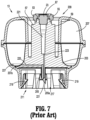
- vial adapter 13 includes a base 201, an adapter support 203 (including a male stem 19 supporting a seal 23 and including guide pins 53, 55, as described above), a spike 205, and an expansion chamber 207.
- Vial adapter 13 includes distal and proximal ends 209, 211.
- base 201 is substantially bowl-shaped and is configured to receive and/or seat an adapter support 203 thereon.
- Vial adapter 13 includes a toroid-shaped expansion chamber 207, including a bladder 227 and translucent cover 215, seated on an inner rim and an outer rim of base 201.
- Bladder 227 having a substantially U-shaped radial cross-section including a first annular rim captured between the outer annular rim of base 201 and the outer annular rim of cover 215, and a second annular rim captured between the inner annular rim of base 201 and the inner annular rim of cover 215.
- Base 201 of vial adapter 13 includes a circular opening 217 along proximal end 211 thereof into which neck “N” of vial “V” is received.
- Retainers 219 are provided around the circumference of opening 217 to connect base 201 of vial adapter 13 to form a permanent connection once the neck “N” of the vial “V” is inserted into opening 217.
- spike 205 extends away from proximal end 211 of base 201 and includes a tip 221 configured to pierce a septum "S" provided on vial “V” when the neck “N” of the vial “V” is inserted into opening 217 of base 201.
- Spike 205 has a length sufficient to extend into the vial "V”.
- Spike 205 is preferably made of plastic, however, it is envisioned that spike 205 may preferably support a metallic piercing member or hypo-tube 205a to assist in the ability of spike 205 to penetrate the septum "S" of the vial "V”.
- spike 205 and adapter support 203 define two ducts 223, 225.
- a first duct 223 extends between tip 221 of spike 205 and lumen 21 of male stem 19, and is provided to permit fluid flow between the vial "V" and male stem 19.
- opening 63 of tip 61 of needle 27 extends into lumen 21 to extract or deliver liquid through duct 223 when syringe adapter 11 is in the open state.
- a second duct 225 extends between tip 221 of spike 205 and a first cavity 207a of chamber 207 defined within expansion chamber 207 when toroid-shaped bladder 227 is deflated.
- Chamber 207a of expansion chamber 207 expands upon a movement of bladder 227 when air or other gas is injected into male stem 19 and duct 223 from a syringe "I" that is attached to syringe adapter 11.
- patient push adapter 15 of the closed fluid transfer system 100 connects to tubing of a patient I.V. set permitting delivery of liquids directly to the patient from a syringe "I" attached to the patient push adapter 15.
- the patient push adapter 15 includes a body 301 having respective distal and proximal ends 303, 305.
- Body 301 of patient push adapter 15 is preferably a one-piece molded plastic part.
- Distal end 303 of patient push adapter 15 includes a male stem 19 defining a lumen 21, having a seal 23 supported across lumen 21, having guide pins 53, 55 projecting radially outward from on outer surface thereof, and having guide surfaces 57, 59 projecting radially outward from on outer surface thereof.
- Proximal end 305 of patient push adapter 15 includes a conventional luer connector 307 configured to accept a mating luer connector of a patient I.V. set "IV" (see FIG. 1 ).
- Lumen 21 extends through body 301, between seal 23 and luer connector 307, permitting fluid flow between the opening 63 of tip 61 of needle 27 and the luer connector 307, when patient push adapter 15 is properly connected to syringe adapter 11, as described above.
- nub 57a, 59a may project from a surface of respective guide surfaces 57, 59 of patient push adapter 15 and which are configured to snap-fit engage respective complementary detents or recesses defined in slots 49, 51 of syringe adapter 11, or more particularly, an appropriately sized annular rib 49a (see FIG. 3 ) formed in an inner surface of halves 43, 45 of housing 25 of syringe adapter 11.
- the interaction of nubs 57a, 59a, and complementary detents or recesses defined in slots 49, 51 or annular rib 49a (see FIGS. 3 and 4 ) of syringe adapter 11 provide a user with audible and/or tactile feedback that patient push adapter 15 and syringe adapter 11 are properly and fully connected to one another.
- Guide surfaces 57, 59 of patient push adapter 15 provide a convenient and comfortable surface for a user to grip patient push adapter 15 and to rotate patient push adapter 15 relative to a conventional luer of I.V. set.
- I.V. bag adapter 17 of the closed fluid transfer system 100 of the present disclosure will be discussed in greater detail.
- the I.V. bag adapter 17 enables liquid to be delivered to, or extracted from, a conventional I.V. bag “B” (see FIG. 1 ).
- the I.V. bag adapter 17 could also be used as a source of ventilation, permitting air to be delivered from a syringe "I” or other source into the I.V. bag to more rapidly drain the I.V. bag “B” of its liquid contents.
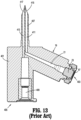
- the I.V. bag adapter 17 includes a body 401 having respective distal and proximal ends 403, 405, and a spike 407 extending from body 401.
- Distal end 403 of I.V. bag adapter 17 includes a male stem 19 defining a lumen 21, having a seal 23 supported across lumen 21, having guide pins 51, 53 projecting radially outward from on outer surface thereof, and having guide surfaces 57, 59 projecting radially outward from on outer surface thereof.
- Body 401 of I.V. bag adapter 17 is preferably a one-piece molded plastic part. Proximal end 405 of body I.V.
- bag adapter 17 includes a conventional port 409 which receives a conventional tapered male connector (not shown) of a conventional infusion chamber (not shown) into which liquid drips from the I.V. bag “B”.
- Spike 407 is tapered between distal and proximal ends 403, 405 for insertion into a conventional port (not shown) of I.V. bag “B”.
- Body 401 of I.V. bag adapter 17 includes two ducts 411, 413.
- First duct 411 is essentially an extension of lumen 21 through spike 407 extending to an opening 415 in spike 407 which would be within I.V. bag “B” when I.V. bag adapter 17 is attached to the I.V. bag “B”.
- Second duct 413 extends between a second opening 417 in spike 407 and a port 409 for attachment to the infusion chamber (not shown).
- opening 63 of tip 61 of needle 27 extends into lumen 21 of male stem 19, when I.V. bag adapter 17 is properly connected to syringe adapter 11, to extract or deliver liquid (or gas) through duct 411 while syringe adapter 11 is in the open state.
- a component other than a syringe adapter 11 could be connected to male stem 19 of I.V. bag adapter 17 to deliver gas to I.V. bag “B".
- Liquid medication delivered through duct 411 may be mixed with the contents of the I.V. bag “B”.
- the liquid in the I.V. bag “B” may then exit the I.V. bag “B” through port 409 and into the infusion chamber for delivery to the patient.
- nub 57a, 59a may project from a surface of respective guide surfaces 57, 59 of I.V. bag adapter 17 and which are configured to snap-fit engage respective complementary detents or recesses defined in slots 49, 51 of syringe adapter 11, or more particularly, an appropriately sized annular channel 49a (see FIG. 3 ) formed in an inner surface of halves 43, 45 of housing 25 of syringe adapter 11.
- the interaction of nubs 57a, 59a and complementary detents or recesses defined in slots 49, 51 or annular rib 49a (see FIGS. 3 and 4 ) of syringe adapter 11 provide a user with audible and/or tactile feedback that I.V. bag adapter 17 and syringe adapter 11 are properly and fully connected to one another.
- closed fluid transfer system 100 including a syringe adapter 11, a vial adapter 13, a patient push adapter 15, an I.V. bag adapter 17, reference may be made to U.S. Patent 9,107,809 , the entire content of which is incorporated herein by reference.
- a preparation system 1000 for automatically or semi-automatically preparing hazardous medicines using syringes, vials, I.V. sets, and I.V bags of the present disclosure, is provided and set forth below.
- Preparation system 1000 includes, as seen in FIG. 14 , at least the following sub-systems and/or stations, namely, at least one gripper (G), a component holder or load tray (CH), a rotation station (RS), a syringe adapter station (SAS), a weigh or reconstitution station (W/RS), an infusion bag station (IBS), a diluent bag station (DBS), a wipe station (WS), and a transfer station (TS).
- Preparation system 1000 may be considered a Closed System Transfer Device (CSTD).
- the Closed System Transfer Device of the present disclosure, has been produced for the safe transfer of potentially hazardous drugs used in the compounding of cancer treatments.
- the CSTD provides a means to make drug transfers between vials, syringes and IV bags without exposing the health care provider to the drug.
- the CSTD early concepts for the CSTD included the possibility of applying the CSTD technology to an automated/robotic application.
- the CSTD, vials, syringes, etc. would be introduced to a standard pharmaceutical hood, then an automatic or semi-automatic preparation system would provide the motion, mixing, etc. required to develop a suitable drug for administration to a patient.
- the primary objective of such an approach would be the reliability, accuracy and repeatability afforded by an automated or semi-automated method.
- the preparation system could be applied to multi-hood environments, improving throughput, and reducing the need for additional personnel, in particular physicians and pharmacologists to scrub and suit up.
- Preparation system 1000 is intended to operate with the confines of an engineering control, e.g., a Class 2 A II BSC (hood).
- hood e.g., a Class 2 A II BSC (hood).
- a characteristic of this type of hood is the provision of air flow vertically downward, emanating from HEPA filters mounted in the ceiling.
- Preparation system 1000 is construction and arranged to maximize or establish 'firstair' flow across each of the stations thereof, e.g., mating, surfaces of each of the components.
- preparation system 1000 includes a frame 1100 having a substantially cubicle configuration made up of a plurality for studs or posts 1102a-1102d each extending along a respective "C" axis, a plurality of first stringers or rails 1104a-1104d each extending along a respective "A" axis and interconnecting selected posts 1102a-1102d, and a plurality of second stringers or rails 1106a-1106d each extending along a respective "B" axis and interconnecting selected posts 1102a-1102d.
- Frame 1100 provides the structure to support motion of various components of preparation system 1000 in a Cartesian horizontal plane.
- Frame 1100 is configured to promote clear air flow from top to bottom while frame 1100 is disposed within a hood (not shown).
- Preparation system 1000 includes a gantry assembly 1110 slidably supported on upper, first stringer or rails 1104b, 1104c of frame 1100, for translation along the "A" axis.
- Gantry assembly 1110 may be supported atop upper, first stringer or rails 1104b, 1104c by bearings, low-friction slides or the like. It is contemplated that any structure or device capable of providing sliding support between gantry assembly 1110 and upper, first stringer or rails 1104b, 1104c may be employed.
- Frame 1100 includes a gantry translation assembly 1108 configured to cause gantry assembly 1110 to translated along upper, first stringer or rails 1104b, 1104c of frame 1100, in the direction of the "A" axis.
- Gantry translation assembly 1108 includes a threaded gantry rod (e.g., screw) 1108a rotatably supported between upper, second stringer or rails 1106b, 1106c of frame 1100, and extending along a respective "A" axis.
- gantry rod e.g., screw
- Gantry translation assembly 1108 further includes a motor 1108b connected to threaded gantry rod 1108a in such a manner that motor 1108b causes threaded gantry rod 1108a to rotate in a first and a second direction (e.g., clockwise and counter-clockwise).
- a motor 1108b connected to threaded gantry rod 1108a in such a manner that motor 1108b causes threaded gantry rod 1108a to rotate in a first and a second direction (e.g., clockwise and counter-clockwise).
- Gantry assembly 1110 includes a pair of rails 1112a, 1112b each extending along a respective "B" axis.
- Gantry assembly 1110 further includes at least one threaded nut structure 1114a which threadably receives threaded gantry rod 1108a of gantry translation assembly 1108 therethrough (e.g., a ballscrew construction or configuration).
- threaded gantry rod 1108a of gantry translation assembly 1108 therethrough (e.g., a ballscrew construction or configuration).
- motor 1108b of gantry translation assembly 1108 rotates threaded gantry rod 1108a
- gantry assembly 1110 is caused to translate along upper, first stringer or rails 1104b, 1104c of frame 1100, in the direction of the "A" axis.
- Preparation system 1000 includes a turntable assembly 1120 slidably supported on rails 1112a, 1112b of gantry assembly 1110, for translation along the "B" axis.
- Turntable assembly 1120 may be supported atop 1112a, 1112b of gantry assembly 1110 by bearings, low-friction slides or the like. It is contemplated that any structure or device capable of providing sliding support between turntable assembly 1120 and 1112a, 1112b may be employed.
- Gantry assembly 1110 includes a turntable translation assembly 1118 configured to cause turntable assembly 1120 to translated along rails 1112a, 1112b of gantry assembly 1110, in the direction of the "B" axis.
- Turntable translation assembly 1118 includes a threaded turntable rod (e.g., screw) 1118a rotatably supported on rail 1112b of gantry assembly 1110, and extending along a respective "B" axis.
- Turntable translation assembly 1118 further includes a motor 1118b connected to threaded turntable rod 1118a in such a manner that motor 1118b causes threaded turntable rod 1118a to rotate in a first and a second direction (e.g., clockwise and counter-clockwise).
- Turntable assembly 1120 includes a platform 1122 supported on rails 1112a, 1112b of gantry assembly 1110.
- Turntable assembly 1120 further includes at least one threaded nut structure (not shown) which threadably receives threaded turntable rod 1118a of turntable translation assembly 1118 therethrough (e.g., a ballscrew construction or configuration).
- threaded turntable rod 1118a of turntable translation assembly 1118 e.g., a ballscrew construction or configuration.
- turntable assembly 1120 is caused to translate along rails 1112a, 1112b of gantry assembly 1110, in the direction of the "B" axis.
- Turntable assembly 1120 includes a spur gear 1124 rotatably supported on platform 1122, wherein an axis of rotation of spur gear 1124 extending in a respective "C" axis.
- Turntable assembly 1120 further includes a rail column 1126 depending from, and non-rotatably connected to, spur gear 1124, wherein rail column 1126 extending along a respective "C” axis.
- Turntable assembly 1120 also includes a first motor 1128a in driving engagement with spur gear 1124 in such a manner that first motor 1128a causes spur gear 1124 to rotate in a first and a second direction (e.g., clockwise and counter-clockwise). Being that rail column 1126 is non-rotatably connected to spur gear 1124, as first motor 1128a rotates spur gear 1124, rail column 1126 is also concomitantly rotated.
- rail column 1126 is provided with rotation by way of a DC brushed gearmotor 1128a. Reversal of first motor 1128a is effected, for example, by computer control of relays acting on opposite polarity power supplies with one providing +12 VDC, and the other providing -12 VDC. Further, it is contemplated that reed switches are provided to assure complete rotation (or a completion of the needed or desired rotation) before subsequent program execution.
- the rotation of rail column 1126 is afforded by way of a pinion gear (not shown) mounted on first motor 1128a which drives spur or bull gear 1124. As mentioned above, rail column 1126 depends through the center of spur gear 1124 and is supported by a four point contact thin wall section bearing.
- Preparation system 1000 includes a carriage 1130 translatably supported on rail column 1126 of turntable assembly 1120. Translation of carriage 1130 along rail column 1126 is achieved by a second motor 1128b of turntable assembly 1120 driving a threaded rod (not shown) extending through rail column 1126 and threadably engaging a threaded nut structure (not shown) fixed to carriage 1130 (e.g., a ballscrew construction or configuration).
- Preparation system 1000 includes a gripper (G) secured to carriage 1130.
- the gripper (G) is responsible for grasping a compounding component, retained in the component holder (CH), removing the compounding component from a station of preparation system 1000 or from the component holder (CH), and then placing compounding component in another station of preparation system 1000.
- the gripper (G) is also responsible for returning a compounding component from a station to the component holder (CH).
- the gripper (G) is further responsible for effecting the assembly and disassembly of the sub-assemblies, specifically a vial (V) and vial adapter 13 sub-assembly (e.g., vial assembly), and a syringe "I” and syringe adapter 11 sub-assembly (e.g., syringe assembly).
- the gripper (G) includes two jaws that can adapt to four components, by way of hermaphroditic jaws 1131 (including a first pair of fixed, opposed jaws 1132, and a second pair of translatable, opposed jaws 1134, wherein one jaw of the first pair of jaws 1132 is interposed between the second pair of jaws 1134, and wherein a second jaw of the second pair of jaws 1134 is interposed between the first pair of jaws 1132) thereof.
- the gripper (G) features jaws 1131 that are coordinated by way of two gear racks and a pinion so that the jaws 1131 always open and close on a fixed center plane.
- the gripper (G) functions by translating the first pair of jaws 1132 and the second pair of jaws 1134 relative to one another to grip a component (e.g., a syringe "I”, a vial “V”, a syringe adapter 11, a vial adapter 13, etc.) in one of a first gripping position (G1), a second gripping position (G2) and a third gripping position (G3).
- a component e.g., a syringe "I”, a vial "V”, a syringe adapter 11, a vial adapter 13, etc.
- the first gripping position (G1) may be located between a first jaw 1132a of the first pair of jaws 1132 and a first jaw 1134a of the second pair of jaws 1134;
- the second gripping position (G2) may be located between the first jaw 1132a of the first pair of jaws 1132 and a second jaw 1134b of the second pair of jaws 1134;
- the third gripping position (G3) may be located between a second jaw 1132b of the first pair of jaws 1132 and the second jaw 1134b of the second pair of jaws 1134.
- the first gripping position (G1) of the gripper (G) may be used to grip a syringe "I”
- the second gripping position (G2) of the gripper (G) may be used to grip a vial adapter 13
- the third gripping position (G3) of the gripper (G) may be used to grip a syringe adapter 11.
- the gripper (G) is configured as hermaphroditic, which configuration allows for multiple uses of each of the gripper positions, for instance the gripping position (G1) can be used to grasp the head or upper extent of syringe "1" as well as the lower extent of syringe "I", thus affording more flexibility.
- the jaws 1131 of the gripper (G) may be actuated by a motor or the like, e.g., Destaco Robohand manipulator.
- the jaws 1131 of the gripper (G) are further configured to provide measurement and error trapping.
- a horizontal linear potentiometer 1136a provides for the diametral measurement of components, such as syringes "I” and vials "V” to ensure the correct diameter is grasped, while a vertical linear potentiometer 1136b is provided for the locating of a raises feature or rib projecting from the vial adapter 13.
- carriage 1130 In use, carriage 1130, and in turn, the gripper (G), is translatable along the length of rail column 1126 upon an actuation of second motor 1128b; and carriage 1130 and the gripper (G) are rotatable about the longitudinal axis of rail column 1126 upon an actuation of first motor 1128a.
- preparation system 1000 includes a component holder or load tray (CH) secured to frame 1100 which is configured to retain moveable components utilized in a compounding cycle of preparation system 1000.
- the moveable components include, as illustrated in FIGS. 1 and 14 , a vial "V", a vial adapter 13, a syringe "I” and a syringe adapter 11.
- the vial adapter 13 may be sized to accommodate a 20mm neck of a vial "V”.
- the vial adapter 13 is staged or retained in a recess (not shown) in the load tray (CH), such that a protective cover of vial adapter 13 resides beneath a top wall of the load tray (CH) and is configured to strip of remove the cover of the vial adapter 13 upon vertical translation of vial adapter 13.
- Load tray (CH) includes recesses formed therein for selectively retaining the moveable components.
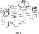
- load tray (CH) may include a recess 1142a configured to retain syringe "I”, and a recess 1142b configured to retain a vial "V".
- Recesses 1142a, 1142b of the load tray (CH) may be configured to have a V-shaped profile and be provided with a respective leaf spring 1143a, 1143b in order to accommodate different diameters of movable components therein.
- the load tray may be configured for support or staging on lower, first stringer or rail 1104a of frame 1100 by way of four posts or the like, and may include a spring loaded plunger and detent feature 1144 for repeated connection disconnection to/from lower, first stringer or rail 1104a.
- preparation system 1000 includes a rotation station (RS) secured to frame 1100 (e.g., to a floor of frame 1100).
- Rotation station (RS) provides a clamping function for the assembly and disassembly of selected moveable components, and provides a rotation function to phase vial adapter 13 for connection with syringe adapter 11.
- Rotation station includes two bull or spur gears 1152a, 1152b are mounted with a small vertical axial clearance therebetween.
- the lower spur gear 1152a is driven by a first motor 1154a, e.g., a bidirectional DC gearmotor, and serves to drive a pinion 1152a1 and a pair of racks 1156e, 1158e for the opening and closing of a pair of jaws 1156, 1158 of rotation station (RS).
- the pair of jaws 1156, 1158 are translatably supported on upper spur gear 1152b by way of rails 1159a, 1159b. Bi-directionality of first motor 1154a is afforded by switching between two opposite polarity power supplies.
- a first actuation of first motor 1154a causes lower spur gear 1152a to rotate in a first direction, and in turn, causes concomitant rotation of pinion 1152a1 in a first direction.
- pinion 1152a1 acts on the pair of racks 1156e, 1158e of the pair of jaws 1156, 1158 to axially slide the pair of racks 1156e, 1158e in a first direction (opposite to one another).
- the pair of racks 1156e, 1158e slide in the first direction, the pair of jaws 1156, 1158 are approximated towards one another (e.g., closing the pair of jaws).
- first motor 1154a causes lower spur gear 1152a to rotate in a second direction (opposite the first direction), and in turn, causes concomitant rotation of pinion 1152a1 in a second direction.
- pinion 1152a1 acts on the pair of racks 1156e, 1158e of the pair of jaws 1156, 1158 to axially slide the pair of racks 1156e, 1158e in a second direction (opposite to one another).
- the pair of jaws 1156, 1158 separate from one another (e.g., opening the pair of jaws).
- the upper spur gear 1152b is responsible for the rotation of the entire rotation station (RS).
- the upper spur gear 1152b is driven by a second motor 1154b, e.g., a DC gearmotor, having a higher ratio than that for the first motor 1154a.
- a second motor 1154b e.g., a DC gearmotor, having a higher ratio than that for the first motor 1154a.
- the jaw or first motor 1154a operates at a higher speed than the rotation or second motor 1154b, such that, during rotation of rotation station (RS), a torque is maintained on a jaw transmission, and a magnetic field of the jaw or first motor 1154a simply slips along at the rate of the second or rotation motor 1154b.
- RS rotation of rotation station
- each jaw 1156, 1158 is configured with passing fingers/walls that define an upper vial position and a lower vial position, increasing the range of vial diameter and length that can be accommodated.
- each jaw 1156, 1158 includes a plurality of spaced apart and parallel walls 1156a, 1158a, respectively, wherein the walls 1156a of first jaw 1156 are in registration or aligned with the gaps defined between walls 1158a of second jaw 1158. In this manner, as the pair of jaws 1156, 1158 are approximated towards one another, the respective walls 1156a, 1158a intermesh or nest with one another.
- first jaw 1156 defines a substantially V-shaped or tapering and converging profile or recess 1156b
- the walls 1158a of second jaw 1158 define a substantially V-shaped or tapering and converging profile or recess 1158b, wherein the recesses 1156b, 1158b are in opposed relation to one another, thus defining the lower vial position.
- Each jaw 1156, 1158 supports a respective upper grip block 1156c, 1158c.
- Each grip block 1156c, 1158c is located near a rear end of respective walls 1156b, 1158b of the pair of jaws 1156, 1158.
- Each grip block 1156c, 1158c defines a respective substantially V-shaped or tapering and converging profile or recess 1156d, 1158d, wherein the recesses 1156d, 1158d are in opposed relation to one another, and wherein the recesses 1156d, 1158d are in registration with the recesses 1156b, 1158b defined by walls 1156a, 1158a, thus defining the upper vial position.
- preparation system 1000 includes a syringe adapter station (SAS) secured to frame 1100.
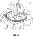
- Syringe adapter station (SAS) includes a platform 1161 rotatably supporting a bull or spur gear 1162 thereon.
- Syringe adapter station (SAS) further includes a pair of spring loaded vertical jaws 1164, 1166 that are synchronized by respective gearing 1164a, 1166a projecting therefrom to coordinate the gripping of a syringe adapter 11.
- the pair of jaws 1164, 1166 are pivotally supported on spur gear 1162 by respective supports 1164b, 1166b projecting from spur gear 1162.
- the pair of jaws 1164, 1166 are disposed between respective uprights 1164c, 1166c projecting from spur gear 1162.
- Each jaw 1164, 1166 includes a respectively, substantially V-shaped notch or recess 1164d, 1166d formed in an end thereof and configured and dimensioned to at least partially surround a syringe adapter 11.
- a pair of respective biasing members 1164e, 1166e is disposed between respective jaws 1164, 1166 and respective uprights 1164c, 1166c.
- Syringe adapter station includes a saw-tooth shaped cup 1168a slidably supported in a floor of platform 1161, and located between the pair of jaws 1164, 1166.
- a biasing member 1168b is provided to urge saw-tooth shaped cup 1168a towards the pair of jaws 1164, 1166 and out of platform 1161.
- Saw-tooth shaped cup 1168a includes at least one tab 1168c projecting radially from a surface thereof and which slidably resides in a channel or groove 1169a of a housing or shroud 1169, wherein the housing 1169 is secured to spur gear 1162.
- a syringe adapter 11 In operation, for an assembly of a syringe adapter 11 and a syringe "I" to one another, a syringe adapter 11 is first retained between the pair of jaws 1164, 1166 of syringe adapter station (SAS) such that luer connector 69 ( FIGS. 1-4 ) of syringe adapter 11 projects away from platform 1161.
- Syringe adapter 11 is seated in saw-tooth shaped cup 1168a in such a manner that syringe adapter 11 may only rotate in a single direction.
- a syringe "I” is picked up from load tray (CH) by gripper (G) and approximated toward syringe adapter station (SAS) by gantry assembly 1110 until a luer connector of the syringe "I” is axially aligned with luer connector 69 of syringe adapter 11, and advanced toward syringe adapter 11 until syringe adapter 11 is pressed slighted against saw-tooth shaped cup 1168a.
- CH load tray
- SAS syringe adapter station
- a motor 1167a (e.g., a bi-directional gearmotor) then rotates spur gear 1161 (in a first direction), by way of a pinion gear 1167b, to rotate syringe adapter 11 relative to syringe "I".
- spur gear 1161 in a first direction
- pinion gear 1167b to rotate syringe adapter 11 relative to syringe "I”.
- saw-tooth shaped cup 1168a preventing syringe adapter 11 from rotating relative to spur gear 1162, as syringe adapter 11 is rotated relative to syringe "I", a connection between the luer connectors thereof is achieved, thereby assembling syringe adapter 11 and syringe "I”.
- saw-tooth shaped cup 1168a rides up and down on surface features provide on the end of syringe adapter 11.
- spur gear 1162 is rotated in an opposite direction by rotating spur gear 1162.
- gripper (G) disengaged from syringe "1”
- the saw-tooth shaped cup 1168a engages features provided in an end of the syringe adapter 11 to thereby provide orientation to the assembled syringe adapter 11 and syringe "I” for later assembly of the syringe adapter 11 to a vial adapter 13, I.V. adapter 15, or I.V. bad adapter 17.
- preparation system 1000 includes a reconstitution station (W/RS) secured to frame 1100.
- Reconstitution station (W/RS) provides agitation for the dissolution of a lyophilized drug.
- reconstitution station (W/RS) may be activated while other compounding is underway in preparation system 1000.
- Reconstitution station includes a turntable 1172 supporting at least three leaf springs 1174a-1174c on a first surface thereof.
- Leaf springs 1174a-1174c are radially arranges around a central axis of rotation of turntable 1172.
- Each leaf spring 1174a-1174c includes a leg portion secured to and extending away from turntable 1172, and an arm portion extending from a free end of a respective leg and toward the central axis of rotation of turntable 1172.
- Leaf springs 1174a-1174c function to stabilize and selectively retain vials of various diameters therebetween.
- Reconstitution station includes a motor 1176 that is in operative engagement with turntable 1172 to provide agitation to turntable 1172, and in turn a vial "V" supported thereon, upon an on-off excitation of motor 1176 via a programmable relay to drive the turntable 1172 through, for example, a gearing arrangement (e.g. a worm gear) or the like.
- a gearing arrangement e.g. a worm gear
- preparation system 1000 includes an infusion bag station (IBS) secured to frame 1100.
- IBS infusion bag station
- IBS is positioned in frame 1100 so that tubes of an infusion bag project away from the moving parts of preparation system 1000.
- Infusion bag station includes a tray 1182 that snaps into a detent 1184 for positioning thereof.
- Infusion bag station (IBS) further includes a bag adapter block 1186 having a shape and/or configuration that is complimentary to and outer profile of I.V. bag adapter 17.
- the I.V. bag adapter 17 and an I.V. bag can be loaded and unloaded into the infusion bag station (IBS) with a single hand, and is/are held in place by a spring loaded arm 1188 of infusion bag station (IBS).
- Tray 1182 includes a sub-tray 1182a, so that, if so desired, sub-tray 1182a can be angled from the horizontal.
- preparation system 1000 includes a diluent bag station (DBS) secured to frame 1100.
- Diluent bag station (DBS) is positioned in frame 1100 so that tubes of a diluent bag project away from the moving parts of preparation system 1000.
- Diluent bag station stages a diluent bag (not shown) for extraction of liquid therefrom for the reconstitution of lyophilized drug.
- Diluent bag station is configured similarly to infusion bag station (IBS), but is further provided with a vertical arm 1192 extending from a tray 1182 thereof.
- Vertical arm 1192 of diluent bag station (DBS) is configured to provide retention of a syringe adapter 11 while diluent (contained in diluent bag) is drawn, via syringe "I", by way of a pair of horizontal fingers 1192a projecting from vertical arm 1192. Specifically, with an I.V.
- bag adapter 17 fluidly connected to a diluent bag (not shown) and to a syringe adapter 11, and with a syringe "I" (having its plunger disposed in an advanced position) fluidly connected to the same syringe adapter 11, as the plunger is withdrawn, fluid or diluent is drawn from diluent bag, through I.V. bag adapter 17 and syringe adapter 11, and into syringe "I".
- Vertical arm 1192 of diluent bag station may be spring loaded to engage the syringe "I", the syringe adapter 11, and the assembly thereof. Vertical arm 1192 is further provided with features to engage the jaws 1132, 1134 of gripper (G) to allow the loading and unloading of the syringe and syringe adapter assembly to/from diluent bag station (DBS).
- preparation system 1000 includes a wipe station (WS) secured to frame 1100.
- Wipe station (WS) is configured to provide an alcohol wipe (not shown) to the glands or seals of the vial adapter 13 and the syringe adapter 11, prior to an assembly to one another. This procedure is consistent with aseptic parts handling and provides additional protection from infection and contamination.
- Wipe station includes a base 1202, a solenoid/spring assembly 1204 supported on baser 1202, a swing arm 1206 supported on base 1202 and operatively connected to solenoid/spring assembly 1204, an alcohol pump and dispersal system (not shown), a tape feed reel 1208 rotatably supported on base 1202 adjacent a first side of solenoid/spring assembly 1204, and take up reel 1210 rotatably supported on base 1202 adjacent a second side of solenoid/spring assembly 1204.
- Wipe station (WS) includes tape (not shown) extending from tape feed reel 1208, around a landing of swing arm 1206, and into take up reel 1210.
- Wipe station (WS) further includes a motor 1212 operatively connected to take up reel 1210 to cause rotation of take up reel 1210 and a drawing out of the tape from tape feed reel 1208.
- a vial adapter 13 or a syringe adapter 11 is picked up from load tray (CH) by gripper (G) and approximated toward wipe station (WS) by gantry assembly 1110 such that the seal thereof is brought into close proximity to the landing of swing arm 1206.
- the solenoid of solenoid/spring assembly 1204 is actuated to move swing arm 1206, and in turn the alcohol moistened tape into contact with the seal.
- take up reel 1210 is rotated to draw the alcohol moistened tape across the seal and disinfect the seal. The process is repeated for the other of the vial adapter 13 or syringe adapter 11.
- preparation system 1000 includes a transfer station (TS) secured to frame 1100.
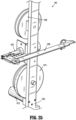
- Transfer station (TS) provides for the transfer of fluids between the syringe "I” and the vial "V".
- Transfer station (TS) is configured for rotation about a horizontal axis by way of a first motor 1222a, e.g., a bidirectional gearmotor, operatively engaged with a bull or spur gear 1224 supported on a fixed frame 1226a.
- Transfer station (TS) further includes a pair of spring loaded jaws 1228a, 1228b for selective engagement with a plunger and plunger flanges of syringe "I”.
- a first jaw 1228a is connected to fixed frame 1226a, and a second jaw 1228b is connected to a movable frame 1226b, wherein the movable frame 1226b is translatable connected to fixed frame 1226a to approximate and/or separate the pair of jaws 1228a, 1228b.
- the pair of jaws 1228a, 1228b may be mounted on linear bearings designed to move with minimal effort to accommodate syringes of differing volumes.
- Transfer station may include a second motor 1222b that is in driving engagement with a threaded rod 1223 that is in threaded engagement with second jaw 1228b, wherein rotation of threaded rod 1223 by second motor 1222b results in translation of second jaw 1228b relative to first jaw 1228a.
- preparation system 1000 of the present disclosure, is highly flexible, with the ability to provide for the compounding of various drug, volumes, diluents, speeds, etc.
- Preparation system 1000 is capable of performing three basic routines for the preparation of a drug, namely, to push a dose from a syringe "I", to inject a dose into an infusion bag (not shown), and to reconstitute lyophilized drug.
- a routine for pushing a dose includes the following steps:
- the present disclosure contemplates a routine for use on or with an infusion bag (not shown).
- the infusion bag routine is similar to the push routine, described above, with the exception that step 7 described above is replaced with the following step: 8.
- Infusion The pair of jaws 1132, 1134 of the gripper (G) engages the full assembly, again by the body and flange of the syringe "I" thereof, and places the full assembly in the rotation station (RS), where the pair of jaws 1156, 1158 of the rotation station (RS) engage the outer diameter of the vial "V" of the full assembly.
- the pair of jaws 1132, 1134 of the gripper (G) With the pair of jaws 1132, 1134 of the gripper (G) engaged with the syringe assembly, the pair of jaws 1164, 1166 of the syringe adapter station (SAS) engages a luer neck of the syringe "I”, and the syringe assembly is then pulled apart from the vial assembly, to separate the assemblies from one another.
- the gripper (G) then separates the syringe assembly and the vial assembly from one another, and brings the syringe assembly to the infusion bag station (IBS) to engage with the I.V. bag adapter 17, by moving syringe assembly vertically downwards (e.g., approximating) onto I.V. bag adapter 17.
- the pair of jaws 1132, 1134 of the gripper (G) then disengage, travel upwards past the plunger of the syringe "I” to then push against the top of the plunger to transfer the contents of the syringe "I” into the I.V. bag (B).
- the pair of jaws 1132, 1134 of the gripper (G) then reengages the syringe assembly and the assemblies are removed as in step 7.
- the present disclosure contemplates a routine for reconstitution.
- the reconstitution routine includes steps 1 through 3, as described above. However, instead of making a prefill, as described in step 4 above, the reconstitution step includes the following step:
- a preparation system 1000 for inhood compounding provides an automated approach to the compounding of drugs, in particular dangerous drugs such as some of those used in oncological chemotherapy.
- Preparation system 1000 is capable of handling drugs in vials, I.V. bags, and the like, within the confines of an engineering control, such as a HEPA washed biological safety cabinet, to provide improved isolation between the operator and the drug.
- Preparation system 1000 further provides fast, accurate, reliable and repeatable compounding in the interests of increased demand and tight economies.
Landscapes
- Engineering & Computer Science (AREA)
- Health & Medical Sciences (AREA)
- Robotics (AREA)
- Mechanical Engineering (AREA)
- General Health & Medical Sciences (AREA)
- Life Sciences & Earth Sciences (AREA)
- Animal Behavior & Ethology (AREA)
- Public Health (AREA)
- Veterinary Medicine (AREA)
- Heart & Thoracic Surgery (AREA)
- Medicinal Chemistry (AREA)
- Chemical & Material Sciences (AREA)
- Nutrition Science (AREA)
- Pharmacology & Pharmacy (AREA)
- Human Computer Interaction (AREA)
- Manufacturing & Machinery (AREA)
- Physics & Mathematics (AREA)
- General Physics & Mathematics (AREA)
- Automation & Control Theory (AREA)
- Hematology (AREA)
- Biomedical Technology (AREA)
- Anesthesiology (AREA)
- Vascular Medicine (AREA)
- Medical Preparation Storing Or Oral Administration Devices (AREA)
- Infusion, Injection, And Reservoir Apparatuses (AREA)
Description
- The present disclosure relates generally to closed fluid transfer systems and their related components, and more particularly, to equipment, components and systems for the transfer of gases/liquids/fluid or other substances from a first container to a second container while maintaining a closed system.
- In one instance, hazardous medicines are frequently applied in the treatment of certain diseases, in particular, for example, in the treatment of cancer. Cytotoxic drugs have generally been used to kill cancer cells. However, the use of cytotoxic drugs, in the treatment of cancer cells, presents specific dangers to all cells, both in the patient and in healthcare providers. Although the exposure to a health care provider is normally very small for each cytotoxic drug dose administration, evidence suggests that chronic, low-dose exposure can produce significant health problems. Accordingly, a system that allows the safe handling of hazardous drugs while significantly reducing and/or eliminating the exposure to providers would be of great benefit.
- Drugs are typically supplied in glass or plastic vials that are capped with a gas impermeable liquid seal or stopper. In some instances, the vial contents are a solid powder, such that a liquid needs to be injected for mixing (e.g., reconstitution). The injection of additional contents (e.g., liquid) into the vial produces an increased pressure which stresses the seal or stopper. Although the vial is intended to be sealed to liquid and gases, drug molecules in vapor phase can leak or pass around the sides of the stopper or through the stopper as the injection needle is withdrawn, thus presenting a hazard to the provider or clinician.
- Accordingly, with the potential for aerosol leakage, leakage/spraying upon needle withdrawal, or spills, a means with which to prevent the accidental vapor phase drug egress is required.
- Thus, the need exists for new equipment, components and systems capable of transferring gases/fluids/liquids or other substances between a conventional syringe and one of a vial, a patient I.V. (intra-venous) set, or an I.V. bag without leaking or spilling and without exposure of the liquids to substances outside the closed system. As such, healthcare personnel may more safely use and handle fluid substances including potentially hazardous liquids and the like.
-
EP 2759498 discloses an automated yarn grasping machine comprising a yarn grasping unit including a gripping mechanism used for gripping a yarn cheese, a rotatinglifting mechanism used for driving the gripping mechanism and a planar moving mechanism which is used for driving the yarn grasping unit to move on a horizontal plane. The planar moving mechanism may comprise a rectangular coordinate planar moving mechanism. -
US 4,466,770 discloses a robotic machine used in the automatic assembly of mechanical and electrical components, having one to four degrees of freedom. A motor assembly machine has X, Y, and Z movable axes and a rotational movement theta about the Z axis. A gripper or tool is mounted on the lower end of the theta axis. The vertical carriage has a rigid elongated housing which is the support structure for the theta axis components. - The present disclosure relates to equipment, components and systems for the transfer of a fluid/substance from a first container to a second container while maintaining a closed system. The invention is defined by appended
claim 1. - According to an aspect of the present disclosure, an automatic or semi-automatic preparation system for forming a medicament solution from a vial containing one of a liquid and a non-liquid material, is provided. The preparation system includes a frame configured to provide three axes of motion. The frame includes a plurality of vertical studs, each stud extending along a respective first axis; a plurality of first stringers extending between and interconnecting selected vertical studs, each first stringer extending along a respective second axis, wherein each second axis is orthogonal to the first axis; and a plurality of second stringers extending between and interconnecting selected vertical studs and selected first stringers, each second stringer extending along a respective third axis, wherein each third axis is orthogonal to the first axis and orthogonal to the second axis.
- The preparation system further includes a gantry assembly translatably supported on at least one of the plurality of first stringers; a gantry translation assembly operatively connected to the gantry assembly, wherein actuation of the gantry translation assembly causes gantry assembly to translate along the at least one of the plurality of first stringers, in a direction parallel to the second axis; and a turntable assembly. The turntable assembly includes a platform translatably supported on gantry assembly; a turntable gear supported on the platform, wherein an axis of rotation of the turntable gear extends in a direction parallel to the first axis; a rail column depending from and non-rotatably connected to the turntable gear, the rail column extending in a direction parallel to the first axis; and a carriage translatably supported on the rail column.
- The gantry translation assembly may include a threaded gantry rod rotatably supported on the frame, the threaded gantry rod being in threaded engagement with a nut structure of the gantry assembly; and a gantry translation motor connected to the threaded gantry rod for rotating the threaded gantry rod in a first direction and a second direction. In operation, rotation of the gantry translation motor in the first direction may cause the gantry assembly to translate in a first direction; and rotation of the gantry translation motor in the second direction may cause the gantry assembly to translate in a second direction.
- The gantry assembly may include a nut structure configured to rotatably receive the threaded gantry rod.
- The gantry translation motor may be supported on the frame.
- The turntable translation assembly may include a threaded turntable rod rotatably supported on the gantry assembly, the threaded turntable rod being in threaded engagement with a nut structure of the turntable assembly; and a turntable translation motor connected to the threaded turntable rod for rotating the threaded turntable rod in a first direction and a second direction. In operation rotation of the turntable translation motor in the first direction may cause the turntable assembly to translate in a first direction; and rotation of the turntable translation motor in the second direction may cause the turntable assembly to translate in a second direction.
- The turntable assembly may include a nut structure configured to rotatably receive the threaded turntable rod.
- The turntable translation motor may be supported on the gantry assembly.
- The gantry assembly may include a turntable rotation motor supported thereon, wherein the turntable rotation motor may be operatively connected to the turntable gear to cause the turntable gear to rotate in a first direction and a second direction.
- The turntable assembly may include a carriage motor in operative communication with the carriage, wherein actuation of the carriage motor results in translation of the carriage along the rail column.
- The turntable assembly includes a component holder supported on the carriage. The component holder may include a gripper having a first pair of fixed, spaced apart jaws, the first pair of jaws including a first jaw and a second jaw; and a second pair of fixed, spaced apart jaws, the second pair of jaws including a first jaw and a second jaw. The first pair of jaws may be translatable relative to the second pair of jaws. The first jaw of the first pair of jaws may be interposed between the second pair of jaws, and the second jaw of the second pair of jaws may be interposed between the first pair of jaws.
- Operation of the gripper may include translation of the first pair of jaws relative to the second pair of jaws to grip a component at a first gripping position located between the first jaw of the first pair of jaws and the first jaw of the second pair of jaws; a second gripping position located between the second jaw of the first pair of jaws and the first jaw of the second pair of jaws; and a third gripping position located between the second jaw of the first pair of jaws and the second jaw of the second pair of jaws.
- The invention will be explained in greater detail below in descriptions of preferred embodiments and referring to the attached figures.
- In the following, the preferred embodiments of invention will be described in detail with reference to the following attached figures:
-
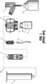
FIG. 1 is a schematic illustration of a closed fluid transfer system, according to the prior art, illustrating a fluid connectability of a syringe to an I.V. Set, a vial and an I.V. bag via combination of a syringe adapter and one of an I.V. set adapter, a vial adapter and an I.V. bag adapter; -
FIG. 2 is a perspective view of a prior art syringe adapter of the closed fluid transfer system ofFIG. 1 ; -
FIG. 3 is a perspective view, with parts separated, of the prior art syringe adapter ofFIG. 2 ; -
FIG. 4 is a longitudinal, cross-sectional view of the prior art syringe adapter ofFIGS. 2 and3 ; -
FIG. 5 is a perspective view of a prior art vial adapter of the closed fluid transfer system ofFIG. 1 ; -
FIG. 6 is a perspective view, with parts separated, of the prior art vial adapter ofFIG. 5 ; -
FIG. 7 is a longitudinal, cross-sectional view of the prior art vial adapter ofFIGS. 5 and6 ; -
FIG. 8 is a top, perspective view of a prior art patient push adapter of the closed fluid transfer system ofFIG. 1 ; -
FIG. 9 is a bottom, perspective view of the prior art patient push adapter of the closed fluid transfer system ofFIG. 1 ; -
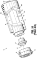
FIG. 10 , is a perspective view, with parts separated, of the prior art patient push adapter ofFIGS. 8 and 9 ; -
FIG. 11 is a longitudinal, cross-sectional view of the prior art patient push adapter ofFIGS. 8-10 ; -
FIG. 12 is a bottom, perspective view of a prior art I.V. bag adapter of the closed fluid transfer system ofFIG. 1 ; -
FIG. 13 is a longitudinal, cross-sectional view of the prior art I.V. bag adapter ofFIG. 12 ; -
FIG. 14 is a perspective view of a preparation system according to an embodiment of the present disclosure; -
FIG. 15 is a first, perspective view of the preparation system ofFIG. 14 , with components removed therefrom; -
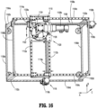
FIG. 16 is a second, perspective view of the preparation system ofFIG. 14 , with components removed therefrom; -
FIG. 17 is a perspective view of a turntable assembly of the preparation system ofFIG. 14 ; -
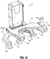
FIG. 18 is a perspective view of a carriage and a gripper of the preparation system ofFIG. 14 ; -
FIG. 19 is a perspective view of a load tray of the preparation system ofFIG. 14 ; -
FIG. 20A is a perspective view of a rotation station of the preparation system ofFIG. 14 ; -
FIG. 20B is a top, plan view of the rotation station ofFIG. 20A ; -
FIG. 21A is a perspective view of a syringe adapter station of the preparation system ofFIG. 14 ; -
FIG. 21B is a further perspective view, with parts separated, of the syringe adapter station ofFIG. 21A ; -
FIG. 21C is a cross-sectional view of the syringe adapter station ofFIGS. 21A-21B as taken through 21C-21C ofFIG. 21A ; -
FIG. 22 is a perspective view of a reconstitution station of the preparation system ofFIG. 14 ; -
FIG. 23 is a perspective view of an infusion bag station of the preparation system ofFIG. 14 ; -
FIG. 24 is a perspective view of a diluent bag station of the preparation system ofFIG. 14 ; -
FIG. 25 is a perspective view of a wipe station of the preparation system ofFIG. 14 ; and -
FIG. 26 is a perspective view of a transfer station of the preparation system ofFIG. 14 . - With reference to
FIGS. 1-13 , a closed fluid transfer system, according to the prior art, is generally designated as 100 and generally includes a module/adapter that fluidly connects to a syringe or any male luer lock connection point; a patient push module/adapter that fluidly connects directly to an I.V. line; at least a module/adapter that fluidly connects to a vial/container storing/containing a fluid/liquid in the form of a hazardous drug and the like; and a module/adapter that fluidly connects to an I.V. bag. Each of the above-mentioned modules/adapters will be described in greater detail below with reference to the accompanying figures, wherein like numbers identify like elements. - The system is a "closed" fluid-transfer system capable of transferring liquids between a conventional syringe and one of a patient I.V. set, a vial, or an I.V. bag without leaking or spilling and without exposure of the gases/fluids/liquids or other substances to a location or a substance outside the closed system. One purpose of the closed fluid transfer system is to permit health care personnel to safely use and handle liquid-form medicine, including potentially hazardous liquid drugs and/or the like.
- The closed
fluid transfer system 100 includes a syringe adapter 11 (seeFIGS. 1-4 ) that is structured to provide a closed fluid connection between a first fluid container in the form of a conventional needleless syringe "I" and a second fluid container/conduit in the form of a patient I.V. set, a vial "V", or an I.V. bag. The fluid transfer is accomplished by first connecting one of a patient push adapter 15 (seeFIGS. 1 and8-11 ) to an I.V. set, a vial adapter 13 (seeFIGS. 1 and5-7 ) to a vial, or an I.V. bag adapter 17 (seeFIGS. 1 and12-13 ) to an I.V. bag, as necessary. Eachadapter internal lumen 21 closed at one end by aresilient seal 23. Thesyringe adapter 11 is mated to themale stem 19, thereby permitting fluid flow from or to the syringe "I". - Referring now specifically to
FIGS. 1-7 , the closedfluid transfer system 100 includes asyringe adapter 11.Syringe adapter 11 is a type of valve which can be in an open state to permit fluid flow therethrough or in a closed state to prevent fluid flow. The open and closed states occur in a specific sequence dictated by thesyringe adapter 11. - The
syringe adapter 11 consists of four main parts which are ahousing 25, a conventionalhollow metal needle 27, ashuttle 29, and acollar 31. Thehousing 25 is generally cylindrical in shape having adistal end 33 and aproximal end 35, alongitudinal axis 37, adistal opening 39, and afemale cavity 41 into which themale stem 19 is received.Housing 25 may be formed to have two housing side portions orhalves housing base portion 47 which fits partially between theside portions Side portions opposed slots 49, 51 (seeFIGS. 2 and4 ) which begin at housingdistal end 33 and extend withinhousing 25.Slots respective guide pin surface male stem 19, which are each keyed to a respective one of theslots 49, 51 (or a respective one ofslots 51, 49), for the purposes described in full detail below. -
Hollow metal needle 27, as seen inFIGS. 3 and4 , is a conventional needle with a sharpenedtip 61, atip end opening 63, aproximal end opening 65, and alumen 67 permitting fluid flow through theconventional needle 27 between theneedle openings needle 27 will be a conventional 18 gauge steel "pencil tip" needle commercially available (18 gauge refers to the outer diameter of needle 27). The conventionalpencil tip needle 27 has an extremelysharp tip 61 with opening 63 spaced slightly away from the sharpenedtip 61. Thepencil tip needle 27 is of a type and size conventionally used with syringes to penetrate patient blood vessels for delivery or extraction of fluids. -
Needle 27 is mounted withinhousing 25, in fixed-positional relationship, on an inner side ofbase 47 withtip 61 ofneedle 27 pointing/extending towarddistal end 33 ofhousing 25. An advantage of this design is thatneedle 27, and specifically, the extremelysharp needle tip 61 ofneedle 27, are fully enclosed within thehousing 25 and are completely shielded from contact with a user. In this manner, the possibility of injuries as a result of user needle-stick, has been significantly reduced and/or eliminated. -
Housing base 47 is rotatably supported inhousing 25.Housing base 47 includes an outer side with aconventional luer connector 69 provided to accept the delivery end of a conventional needless syringe. Alumen 71 extends throughbase 47 betweenluer connector 69 andproximal opening 65 ofneedle 27 permitting fluid flow between theneedle tip opening 63 and theluer connector 69. -
Housing 25 andhousing base 47 ofsyringe adapter 11 cooperate with one another to provide a ratchet mechanism by whichsyringe adapter 11 may not be accidentally or inadvertently disconnected from syringe "I". In particular, the ratchet mechanism includes, as seen inFIG. 3 , a plurality ofribs 25a formed on an inner surface ofhousing 25 and at least oneresilient finger 47a supported onhousing base 47, wherebyhousing base 47 is held in a fixed position relative tohousing 25 whensyringe adapter 11 is connected tosyringe 11 and to is free to rotate relative tohousing 25 ifsyringe adapter 11 is being inadvertently or accidently disconnected from syringe "I". In this manner, the closed system between thesyringe adapter 11 andsyringe 11 is better maintained. - Generally, in operation, when
syringe adapter 11 is connected to syringe "I", the at least oneresilient finger 47a ofhousing base 47 engagesribs 25a of housing in such a manner that rotation ofhousing base 47 relative tohousing 25 is inhibited andsyringe adapter 11 may be securely connected to syringe "I". Further, if there is an inadvertent or accidental rotation ofsyringe adapter 11 relative to syringe "I", tending to disconnectsyringe adapter 11 from syringe "I", and thus destroy the closed system, eachresilient finger 47a is configured to slip over and acrossribs 25a ofhousing 25, allowinghousing base 47 to rotate relative tohousing 25 and thus maintain the closed system. - If it is desired to intentionally disconnect syringe "I" from
syringe adapter 11, a user may squeezehousing 25 radially inward, in the proximity ofluer connector 69, to engage at least one tooth (not shown) formed on an inner surface ofhousing 25 with arespective notch 47b formed in an outer surface ofhousing base 47. Then, with the at least one tooth (not shown) ofhousing 25 engaged with therespective notch 47b ofhousing base 47, the user may rotatesyringe adapter 11 relative to syringe "I" to disconnect syringe "I" fromluer connector 69 ofhousing base 47. -
Shuttle 29 is provided for at least the following important purposes. First,shuttle 29 supports shuttledistal seal 73 acrossdistal opening 39 ofhousing 25 to closecavity 41 ofhousing 25 so that contaminants cannot enter thehousing 25 when thesyringe adapter 11 is not mated to one of theadapters shuttle 29 supports shuttledistal seal 73 at a position acrossdistal opening 39 ofhousing 25 so thatdistal seal 73 can be easily swabbed with alcohol before use to ensure that theseal 73 is sterile. In accordance with the present disclosure, and as is customary, aseal 23 of any male stem 19 (as seen in for exampleFIG. 5 and as will be described in greater detail below) is also swabbed with alcohol or other microbial agent before being mated to thesyringe adapter 11, so as to ensure sterility of the abutment betweenseals shuttle 29 provides a fluid-tight enclosure forneedle 27 to prevent fluid flow outside ofsyringe adapter 11 when in the closed state. - As illustrated in
FIGS. 3 and4 ,shuttle 29 includes distal and proximalannular flanges intermediate body portion 79 betweenflanges shuttle lumen 81 therethrough.Distal flange 75 supports adistal seal 73 and abarrel 83, seated ondistal flange 75, holdsdistal seal 73 ondistal flange 75. Shuttleproximal flange 77 supports aproximal seal 85. - As illustrated in
FIGS. 3 and4 ,tip 61 ofneedle 27 extends intoshuttle lumen 81 andproximal seal 85 forms a fluid-tight seal aroundneedle 27. In the closed state, whensyringe adapter 11 is fluidly connected to syringe "I",needle tip 61 andopening 63 are withinshuttle lumen 81 and seals 73, 85 prevent fluid from exitingshuttle lumen 81. - Each
seal outward projection 87, 89 (i.e., convex surface) which abut one another when theseals Seals seals seals -
Intermediate portion 79 ofshuttle 29 rides incollar opening 91 incollar end wall 93 ofcollar 31 for axial movement alongaxis 37 withinhousing 25.Barrel 83 is generally cylindrical in shape and has an outside diameter slightly less than an inside diameter ofcollar 31 to permitbarrel 83 andshuttle 29 to reciprocate insidecollar 31. - A
spring 95 is provided and bears againstend wall 93 ofcollar 31 anddistal flange 75, partially withinbarrel 83.Spring 95 biases shuttle 29 towarddistal end 33 ofhousing 25 so thatdistal seal 73 ofshuttle 29 covers or extends across opening 39 ofhousing 25, for the reasons previously described. Spring-biased contact betweenbarrel 83 andend wall 93 ofcollar 31 limits inward movement ofshuttle 29 towardproximal end 35 ofhousing 25, and contact betweenproximal flange 77 ofshuttle 29 andend wall 93 ofcollar 31 limits outward movement ofshuttle 29 towarddistal end 33 ofhousing 25. -
Distal seal 73 ofshuttle 29 does not contact thehousing 25 and is supported solely byshuttle 29 and travels withincollar 31 spaced fromhousing 25.Shuttle 29 is pushed axially towardproximal end 35 ofhousing 25 when contacted byseal 23 of anymale stem 19 during use, as described more fully below. - With continued reference to
FIGS. 2-4 ,collar 31 andhousing 25 cooperate to holdmale stem 19 and seal 23 (for example, as seen inFIG. 8 ) thereof in abutment withdistal seal 73 ofshuttle 29 so that the abuttingseals needle tip 61 ofneedle 27 and so thatneedle 27 can enterlumen 21 ofmale stem 19 to open the fluid path throughsyringe adapter 11. The abutment betweenseals distal seal 73 ofshuttle 29 is the closure fordistal opening 39 ofhousing 25 and also placesdistal seal 73 ofshuttle 29 in a position convenient for swabbing with alcohol before use. The abutment betweenseals seals needle 27. If theseals lumen 81 ofshuttle 29, liquids could leak intocavity 41 ofhousing 25, which is contrary to the purpose of providing a closed system. - Referring now to
FIGS. 3-4 ,collar 31 is generally cylindrical in shape corresponding to the shape ofcavity 41 ofhousing 25.Collar 31 includes aproximal end wall 93 and a side wall 97 extending fromproximal wall 93. - Turning now to
FIGS. 1 and5-7 ,vial adapter 13 of the closedfluid transfer system 100 will be discussed in greater detail. Generally,vial adapter 13 connects to a neck "N" of a vial, bottle, or other container "V" holding liquid "L" to be extracted or into which liquid is to be delivered For convenience, these containers will be referred to collectively by the term "vial."Vial adapter 13 may be provided in sizes and configurations as necessary to attach to commercially-available vials. - As illustrated in
FIGS. 5-7 ,vial adapter 13 includes abase 201, an adapter support 203 (including amale stem 19 supporting aseal 23 and including guide pins 53, 55, as described above), aspike 205, and anexpansion chamber 207.Vial adapter 13 includes distal and proximal ends 209, 211. - As best shown in
FIGS. 6 and7 ,base 201 is substantially bowl-shaped and is configured to receive and/or seat anadapter support 203 thereon.Vial adapter 13 includes a toroid-shapedexpansion chamber 207, including abladder 227 andtranslucent cover 215, seated on an inner rim and an outer rim ofbase 201.Bladder 227 having a substantially U-shaped radial cross-section including a first annular rim captured between the outer annular rim ofbase 201 and the outer annular rim ofcover 215, and a second annular rim captured between the inner annular rim ofbase 201 and the inner annular rim ofcover 215. -
Base 201 ofvial adapter 13 includes acircular opening 217 alongproximal end 211 thereof into which neck "N" of vial "V" is received.Retainers 219 are provided around the circumference ofopening 217 to connectbase 201 ofvial adapter 13 to form a permanent connection once the neck "N" of the vial "V" is inserted intoopening 217. - As seen in
FIG. 7 , spike 205 extends away fromproximal end 211 ofbase 201 and includes atip 221 configured to pierce a septum "S" provided on vial "V" when the neck "N" of the vial "V" is inserted into opening 217 ofbase 201.Spike 205 has a length sufficient to extend into the vial "V".Spike 205 is preferably made of plastic, however, it is envisioned thatspike 205 may preferably support a metallic piercing member or hypo-tube 205a to assist in the ability ofspike 205 to penetrate the septum "S" of the vial "V". - As seen in
FIG. 7 , spike 205 andadapter support 203 define twoducts first duct 223 extends betweentip 221 ofspike 205 andlumen 21 ofmale stem 19, and is provided to permit fluid flow between the vial "V" andmale stem 19. As described above, opening 63 oftip 61 ofneedle 27 extends intolumen 21 to extract or deliver liquid throughduct 223 whensyringe adapter 11 is in the open state. Asecond duct 225 extends betweentip 221 ofspike 205 and afirst cavity 207a ofchamber 207 defined withinexpansion chamber 207 when toroid-shapedbladder 227 is deflated.Chamber 207a ofexpansion chamber 207 expands upon a movement ofbladder 227 when air or other gas is injected intomale stem 19 andduct 223 from a syringe "I" that is attached tosyringe adapter 11. - Turning now to
FIGS. 1 and8-11 ,patient push adapter 15 of the closedfluid transfer system 100 will be discussed in greater detail. In general,patient push adapter 15 connects to tubing of a patient I.V. set permitting delivery of liquids directly to the patient from a syringe "I" attached to thepatient push adapter 15. - The
patient push adapter 15 includes abody 301 having respective distal and proximal ends 303, 305.Body 301 ofpatient push adapter 15 is preferably a one-piece molded plastic part.Distal end 303 ofpatient push adapter 15 includes amale stem 19 defining alumen 21, having aseal 23 supported acrosslumen 21, having guide pins 53, 55 projecting radially outward from on outer surface thereof, and having guide surfaces 57, 59 projecting radially outward from on outer surface thereof.Proximal end 305 ofpatient push adapter 15 includes aconventional luer connector 307 configured to accept a mating luer connector of a patient I.V. set "IV" (seeFIG. 1 ).Lumen 21 extends throughbody 301, betweenseal 23 andluer connector 307, permitting fluid flow between the opening 63 oftip 61 ofneedle 27 and theluer connector 307, whenpatient push adapter 15 is properly connected tosyringe adapter 11, as described above. - With reference to
FIGS. 8-10 , it is contemplated that at least onenub patient push adapter 15 and which are configured to snap-fit engage respective complementary detents or recesses defined inslots syringe adapter 11, or more particularly, an appropriately sizedannular rib 49a (seeFIG. 3 ) formed in an inner surface ofhalves housing 25 ofsyringe adapter 11. The interaction ofnubs slots annular rib 49a (seeFIGS. 3 and4 ) ofsyringe adapter 11 provide a user with audible and/or tactile feedback thatpatient push adapter 15 andsyringe adapter 11 are properly and fully connected to one another. - Guide surfaces 57, 59 of
patient push adapter 15 provide a convenient and comfortable surface for a user to grippatient push adapter 15 and to rotatepatient push adapter 15 relative to a conventional luer of I.V. set. - Turning now to
FIGS. 1 and12-13 , I.V.bag adapter 17 of the closedfluid transfer system 100 of the present disclosure, will be discussed in greater detail. In general, the I.V.bag adapter 17 enables liquid to be delivered to, or extracted from, a conventional I.V. bag "B" (seeFIG. 1 ). The I.V.bag adapter 17 could also be used as a source of ventilation, permitting air to be delivered from a syringe "I" or other source into the I.V. bag to more rapidly drain the I.V. bag "B" of its liquid contents. - The I.V.
bag adapter 17 includes abody 401 having respective distal and proximal ends 403, 405, and aspike 407 extending frombody 401.Distal end 403 of I.V.bag adapter 17 includes amale stem 19 defining alumen 21, having aseal 23 supported acrosslumen 21, having guide pins 51, 53 projecting radially outward from on outer surface thereof, and having guide surfaces 57, 59 projecting radially outward from on outer surface thereof.Body 401 of I.V.bag adapter 17 is preferably a one-piece molded plastic part.Proximal end 405 of body I.V.bag adapter 17 includes aconventional port 409 which receives a conventional tapered male connector (not shown) of a conventional infusion chamber (not shown) into which liquid drips from the I.V. bag "B".Spike 407 is tapered between distal and proximal ends 403, 405 for insertion into a conventional port (not shown) of I.V. bag "B". -
Body 401 of I.V.bag adapter 17 includes twoducts First duct 411 is essentially an extension oflumen 21 throughspike 407 extending to anopening 415 inspike 407 which would be within I.V. bag "B" when I.V.bag adapter 17 is attached to the I.V. bag "B".Second duct 413 extends between asecond opening 417 inspike 407 and aport 409 for attachment to the infusion chamber (not shown). As described above, opening 63 oftip 61 ofneedle 27 extends intolumen 21 ofmale stem 19, when I.V.bag adapter 17 is properly connected tosyringe adapter 11, to extract or deliver liquid (or gas) throughduct 411 whilesyringe adapter 11 is in the open state. - In accordance with the present disclosure, a component other than a
syringe adapter 11 could be connected tomale stem 19 of I.V.bag adapter 17 to deliver gas to I.V. bag "B". Liquid medication delivered throughduct 411 may be mixed with the contents of the I.V. bag "B". The liquid in the I.V. bag "B" may then exit the I.V. bag "B" throughport 409 and into the infusion chamber for delivery to the patient. - With reference to
FIGS. 12 and15 , it is contemplated that at least onenub bag adapter 17 and which are configured to snap-fit engage respective complementary detents or recesses defined inslots syringe adapter 11, or more particularly, an appropriately sizedannular channel 49a (seeFIG. 3 ) formed in an inner surface ofhalves housing 25 ofsyringe adapter 11. The interaction ofnubs slots annular rib 49a (seeFIGS. 3 and4 ) ofsyringe adapter 11 provide a user with audible and/or tactile feedback that I.V.bag adapter 17 andsyringe adapter 11 are properly and fully connected to one another. - For a detailed description of the construction and operation of closed
fluid transfer system 100 including asyringe adapter 11, avial adapter 13, apatient push adapter 15, an I.V.bag adapter 17, reference may be made toU.S. Patent 9,107,809 - Turning now to
FIGS. 14-26 , in accordance with the present disclosure, apreparation system 1000 for automatically or semi-automatically preparing hazardous medicines using syringes, vials, I.V. sets, and I.V bags of the present disclosure, is provided and set forth below. -
Preparation system 1000 includes, as seen inFIG. 14 , at least the following sub-systems and/or stations, namely, at least one gripper (G), a component holder or load tray (CH), a rotation station (RS), a syringe adapter station (SAS), a weigh or reconstitution station (W/RS), an infusion bag station (IBS), a diluent bag station (DBS), a wipe station (WS), and a transfer station (TS).Preparation system 1000 may be considered a Closed System Transfer Device (CSTD). - The Closed System Transfer Device (CSTD) of the present disclosure, has been produced for the safe transfer of potentially hazardous drugs used in the compounding of cancer treatments. The CSTD provides a means to make drug transfers between vials, syringes and IV bags without exposing the health care provider to the drug.
- Early concepts for the CSTD included the possibility of applying the CSTD technology to an automated/robotic application. In this application, the CSTD, vials, syringes, etc. would be introduced to a standard pharmaceutical hood, then an automatic or semi-automatic preparation system would provide the motion, mixing, etc. required to develop a suitable drug for administration to a patient. The primary objective of such an approach would be the reliability, accuracy and repeatability afforded by an automated or semi-automated method. Further, the preparation system could be applied to multi-hood environments, improving throughput, and reducing the need for additional personnel, in particular physicians and pharmacologists to scrub and suit up.
-
Preparation system 1000 is intended to operate with the confines of an engineering control, e.g., a Class 2 A II BSC (hood). A characteristic of this type of hood is the provision of air flow vertically downward, emanating from HEPA filters mounted in the ceiling.Preparation system 1000 is construction and arranged to maximize or establish 'firstair' flow across each of the stations thereof, e.g., mating, surfaces of each of the components. - Turning now to
FIGS. 14-16 ,preparation system 1000 includes aframe 1100 having a substantially cubicle configuration made up of a plurality for studs orposts 1102a-1102d each extending along a respective "C" axis, a plurality of first stringers orrails 1104a-1104d each extending along a respective "A" axis and interconnecting selectedposts 1102a-1102d, and a plurality of second stringers orrails 1106a-1106d each extending along a respective "B" axis and interconnecting selectedposts 1102a-1102d.Frame 1100 provides the structure to support motion of various components ofpreparation system 1000 in a Cartesian horizontal plane.Frame 1100 is configured to promote clear air flow from top to bottom whileframe 1100 is disposed within a hood (not shown). -
Preparation system 1000 includes agantry assembly 1110 slidably supported on upper, first stringer orrails frame 1100, for translation along the "A" axis.Gantry assembly 1110 may be supported atop upper, first stringer orrails gantry assembly 1110 and upper, first stringer orrails -
Frame 1100 includes agantry translation assembly 1108 configured to causegantry assembly 1110 to translated along upper, first stringer orrails frame 1100, in the direction of the "A" axis.Gantry translation assembly 1108 includes a threaded gantry rod (e.g., screw) 1108a rotatably supported between upper, second stringer orrails frame 1100, and extending along a respective "A" axis.Gantry translation assembly 1108 further includes amotor 1108b connected to threadedgantry rod 1108a in such a manner that motor 1108b causes threadedgantry rod 1108a to rotate in a first and a second direction (e.g., clockwise and counter-clockwise). -
Gantry assembly 1110 includes a pair ofrails Gantry assembly 1110 further includes at least one threadednut structure 1114a which threadably receives threadedgantry rod 1108a ofgantry translation assembly 1108 therethrough (e.g., a ballscrew construction or configuration). In operation, asmotor 1108b ofgantry translation assembly 1108 rotates threadedgantry rod 1108a,gantry assembly 1110 is caused to translate along upper, first stringer orrails frame 1100, in the direction of the "A" axis. -
Preparation system 1000 includes aturntable assembly 1120 slidably supported onrails gantry assembly 1110, for translation along the "B" axis.Turntable assembly 1120 may be supported atop 1112a, 1112b ofgantry assembly 1110 by bearings, low-friction slides or the like. It is contemplated that any structure or device capable of providing sliding support betweenturntable assembly -
Gantry assembly 1110 includes aturntable translation assembly 1118 configured to causeturntable assembly 1120 to translated alongrails gantry assembly 1110, in the direction of the "B" axis.Turntable translation assembly 1118 includes a threaded turntable rod (e.g., screw) 1118a rotatably supported onrail 1112b ofgantry assembly 1110, and extending along a respective "B" axis.Turntable translation assembly 1118 further includes amotor 1118b connected to threadedturntable rod 1118a in such a manner that motor 1118b causes threadedturntable rod 1118a to rotate in a first and a second direction (e.g., clockwise and counter-clockwise). -
Turntable assembly 1120 includes aplatform 1122 supported onrails gantry assembly 1110.Turntable assembly 1120 further includes at least one threaded nut structure (not shown) which threadably receives threadedturntable rod 1118a ofturntable translation assembly 1118 therethrough (e.g., a ballscrew construction or configuration). In operation, asmotor 1118b ofturntable translation assembly 1118 rotates threadedturntable rod 1118a,turntable assembly 1120 is caused to translate alongrails gantry assembly 1110, in the direction of the "B" axis. -
Turntable assembly 1120 includes aspur gear 1124 rotatably supported onplatform 1122, wherein an axis of rotation ofspur gear 1124 extending in a respective "C" axis.Turntable assembly 1120 further includes arail column 1126 depending from, and non-rotatably connected to,spur gear 1124, whereinrail column 1126 extending along a respective "C" axis.Turntable assembly 1120 also includes afirst motor 1128a in driving engagement withspur gear 1124 in such a manner thatfirst motor 1128a causesspur gear 1124 to rotate in a first and a second direction (e.g., clockwise and counter-clockwise). Being thatrail column 1126 is non-rotatably connected to spurgear 1124, asfirst motor 1128a rotatesspur gear 1124,rail column 1126 is also concomitantly rotated. - Specifically,
rail column 1126 is provided with rotation by way of a DC brushedgearmotor 1128a. Reversal offirst motor 1128a is effected, for example, by computer control of relays acting on opposite polarity power supplies with one providing +12 VDC, and the other providing -12 VDC. Further, it is contemplated that reed switches are provided to assure complete rotation (or a completion of the needed or desired rotation) before subsequent program execution. The rotation ofrail column 1126 is afforded by way of a pinion gear (not shown) mounted onfirst motor 1128a which drives spur orbull gear 1124. As mentioned above,rail column 1126 depends through the center ofspur gear 1124 and is supported by a four point contact thin wall section bearing. -
Preparation system 1000 includes acarriage 1130 translatably supported onrail column 1126 ofturntable assembly 1120. Translation ofcarriage 1130 alongrail column 1126 is achieved by asecond motor 1128b ofturntable assembly 1120 driving a threaded rod (not shown) extending throughrail column 1126 and threadably engaging a threaded nut structure (not shown) fixed to carriage 1130 (e.g., a ballscrew construction or configuration). -
Preparation system 1000 includes a gripper (G) secured tocarriage 1130. The gripper (G) is responsible for grasping a compounding component, retained in the component holder (CH), removing the compounding component from a station ofpreparation system 1000 or from the component holder (CH), and then placing compounding component in another station ofpreparation system 1000. The gripper (G) is also responsible for returning a compounding component from a station to the component holder (CH). The gripper (G) is further responsible for effecting the assembly and disassembly of the sub-assemblies, specifically a vial (V) andvial adapter 13 sub-assembly (e.g., vial assembly), and a syringe "I" andsyringe adapter 11 sub-assembly (e.g., syringe assembly). - With reference to
FIGS. 17 and18 , the gripper (G) includes two jaws that can adapt to four components, by way of hermaphroditic jaws 1131 (including a first pair of fixed,opposed jaws 1132, and a second pair of translatable,opposed jaws 1134, wherein one jaw of the first pair ofjaws 1132 is interposed between the second pair ofjaws 1134, and wherein a second jaw of the second pair ofjaws 1134 is interposed between the first pair of jaws 1132) thereof. The gripper (G) featuresjaws 1131 that are coordinated by way of two gear racks and a pinion so that thejaws 1131 always open and close on a fixed center plane. - As illustrated in
FIG. 18 , the gripper (G) functions by translating the first pair ofjaws 1132 and the second pair ofjaws 1134 relative to one another to grip a component (e.g., a syringe "I", a vial "V", asyringe adapter 11, avial adapter 13, etc.) in one of a first gripping position (G1), a second gripping position (G2) and a third gripping position (G3). The first gripping position (G1) may be located between afirst jaw 1132a of the first pair ofjaws 1132 and afirst jaw 1134a of the second pair ofjaws 1134; the second gripping position (G2) may be located between thefirst jaw 1132a of the first pair ofjaws 1132 and asecond jaw 1134b of the second pair ofjaws 1134; and the third gripping position (G3) may be located between asecond jaw 1132b of the first pair ofjaws 1132 and thesecond jaw 1134b of the second pair ofjaws 1134. - By way of example only, the first gripping position (G1) of the gripper (G) may be used to grip a syringe "I", the second gripping position (G2) of the gripper (G) may be used to grip a
vial adapter 13, and the third gripping position (G3) of the gripper (G) may be used to grip asyringe adapter 11. - The gripper (G) is configured as hermaphroditic, which configuration allows for multiple uses of each of the gripper positions, for instance the gripping position (G1) can be used to grasp the head or upper extent of syringe "1" as well as the lower extent of syringe "I", thus affording more flexibility. The
jaws 1131 of the gripper (G) may be actuated by a motor or the like, e.g., Destaco Robohand manipulator. Thejaws 1131 of the gripper (G) are further configured to provide measurement and error trapping. For example, a horizontallinear potentiometer 1136a provides for the diametral measurement of components, such as syringes "I" and vials "V" to ensure the correct diameter is grasped, while a verticallinear potentiometer 1136b is provided for the locating of a raises feature or rib projecting from thevial adapter 13. - In use,
carriage 1130, and in turn, the gripper (G), is translatable along the length ofrail column 1126 upon an actuation ofsecond motor 1128b; andcarriage 1130 and the gripper (G) are rotatable about the longitudinal axis ofrail column 1126 upon an actuation offirst motor 1128a. - Turning now to
FIGS. 14 and19 ,preparation system 1000 includes a component holder or load tray (CH) secured to frame 1100 which is configured to retain moveable components utilized in a compounding cycle ofpreparation system 1000. The moveable components include, as illustrated inFIGS. 1 and14 , a vial "V", avial adapter 13, a syringe "I" and asyringe adapter 11. Thevial adapter 13 may be sized to accommodate a 20mm neck of a vial "V". Thevial adapter 13 is staged or retained in a recess (not shown) in the load tray (CH), such that a protective cover ofvial adapter 13 resides beneath a top wall of the load tray (CH) and is configured to strip of remove the cover of thevial adapter 13 upon vertical translation ofvial adapter 13. - Load tray (CH) includes recesses formed therein for selectively retaining the moveable components. For example, load tray (CH) may include a
recess 1142a configured to retain syringe "I", and arecess 1142b configured to retain a vial "V".Recesses respective leaf spring - The load tray (CH) may be configured for support or staging on lower, first stringer or
rail 1104a offrame 1100 by way of four posts or the like, and may include a spring loaded plunger anddetent feature 1144 for repeated connection disconnection to/from lower, first stringer orrail 1104a. - Turning now to
FIGS. 14 and20A-20B ,preparation system 1000 includes a rotation station (RS) secured to frame 1100 (e.g., to a floor of frame 1100). Rotation station (RS) provides a clamping function for the assembly and disassembly of selected moveable components, and provides a rotation function to phasevial adapter 13 for connection withsyringe adapter 11. - Rotation station (RS) includes two bull or
spur gears lower spur gear 1152a is driven by afirst motor 1154a, e.g., a bidirectional DC gearmotor, and serves to drive a pinion 1152a1 and a pair ofracks jaws jaws upper spur gear 1152b by way ofrails first motor 1154a is afforded by switching between two opposite polarity power supplies. - In operation, a first actuation of
first motor 1154a causeslower spur gear 1152a to rotate in a first direction, and in turn, causes concomitant rotation of pinion 1152a1 in a first direction. As pinion 1152a1 is rotated in the first direction, pinion 1152a1 acts on the pair ofracks jaws racks racks jaws first motor 1154a (opposite the first actuation) causeslower spur gear 1152a to rotate in a second direction (opposite the first direction), and in turn, causes concomitant rotation of pinion 1152a1 in a second direction. As pinion 1152a1 is rotated in the second direction, pinion 1152a1 acts on the pair ofracks jaws racks racks jaws - The
upper spur gear 1152b is responsible for the rotation of the entire rotation station (RS). Theupper spur gear 1152b is driven by asecond motor 1154b, e.g., a DC gearmotor, having a higher ratio than that for thefirst motor 1154a. Thus the pair ofjaws upper spur gear 1152b. - It is contemplated that the jaw or
first motor 1154a operates at a higher speed than the rotation orsecond motor 1154b, such that, during rotation of rotation station (RS), a torque is maintained on a jaw transmission, and a magnetic field of the jaw orfirst motor 1154a simply slips along at the rate of the second orrotation motor 1154b. - The pair of
jaws jaw parallel walls walls 1156a offirst jaw 1156 are in registration or aligned with the gaps defined betweenwalls 1158a ofsecond jaw 1158. In this manner, as the pair ofjaws respective walls walls 1156a offirst jaw 1156 define a substantially V-shaped or tapering and converging profile orrecess 1156b, and thewalls 1158a ofsecond jaw 1158 define a substantially V-shaped or tapering and converging profile orrecess 1158b, wherein therecesses - Each
jaw upper grip block grip block respective walls jaws grip block recess recesses recesses recesses walls - Turning now to
FIGS. 14 , and21A-21C ,preparation system 1000 includes a syringe adapter station (SAS) secured to frame 1100. Syringe adapter station (SAS) includes aplatform 1161 rotatably supporting a bull orspur gear 1162 thereon. Syringe adapter station (SAS) further includes a pair of spring loadedvertical jaws respective gearing syringe adapter 11. The pair ofjaws spur gear 1162 byrespective supports spur gear 1162. The pair ofjaws respective uprights spur gear 1162. Eachjaw recess syringe adapter 11. A pair ofrespective biasing members respective jaws respective uprights - Syringe adapter station (SAS) includes a saw-tooth shaped
cup 1168a slidably supported in a floor ofplatform 1161, and located between the pair ofjaws member 1168b is provided to urge saw-tooth shapedcup 1168a towards the pair ofjaws platform 1161. Saw-tooth shapedcup 1168a includes at least onetab 1168c projecting radially from a surface thereof and which slidably resides in a channel orgroove 1169a of a housing orshroud 1169, wherein thehousing 1169 is secured to spurgear 1162. - In operation, for an assembly of a
syringe adapter 11 and a syringe "I" to one another, asyringe adapter 11 is first retained between the pair ofjaws FIGS. 1-4 ) ofsyringe adapter 11 projects away fromplatform 1161.Syringe adapter 11 is seated in saw-tooth shapedcup 1168a in such a manner thatsyringe adapter 11 may only rotate in a single direction. Next, a syringe "I", is picked up from load tray (CH) by gripper (G) and approximated toward syringe adapter station (SAS) bygantry assembly 1110 until a luer connector of the syringe "I" is axially aligned withluer connector 69 ofsyringe adapter 11, and advanced towardsyringe adapter 11 untilsyringe adapter 11 is pressed slighted against saw-tooth shapedcup 1168a. - A
motor 1167a (e.g., a bi-directional gearmotor) then rotates spur gear 1161 (in a first direction), by way of apinion gear 1167b, to rotatesyringe adapter 11 relative to syringe "I". With saw-tooth shapedcup 1168a preventingsyringe adapter 11 from rotating relative to spurgear 1162, assyringe adapter 11 is rotated relative to syringe "I", a connection between the luer connectors thereof is achieved, thereby assemblingsyringe adapter 11 and syringe "I". During assembly, saw-tooth shapedcup 1168a rides up and down on surface features provide on the end ofsyringe adapter 11. - Once
syringe adapter 11 and syringe "I" are assembled,spur gear 1162 is rotated in an opposite direction by rotatingspur gear 1162. As the assembledsyringe adapter 11 and syringe "I" are rotated in the opposite direction, with gripper (G) disengaged from syringe "1", the saw-tooth shapedcup 1168a engages features provided in an end of thesyringe adapter 11 to thereby provide orientation to the assembledsyringe adapter 11 and syringe "I" for later assembly of thesyringe adapter 11 to avial adapter 13, I.V.adapter 15, or I.V.bad adapter 17. - Turning now to
FIGS. 14 and22 ,preparation system 1000 includes a reconstitution station (W/RS) secured to frame 1100. Reconstitution station (W/RS) provides agitation for the dissolution of a lyophilized drug. In operation, reconstitution station (W/RS) may be activated while other compounding is underway inpreparation system 1000. - Reconstitution station (W/RS) includes a
turntable 1172 supporting at least threeleaf springs 1174a-1174c on a first surface thereof. Leaf springs 1174a-1174c are radially arranges around a central axis of rotation ofturntable 1172. Eachleaf spring 1174a-1174c includes a leg portion secured to and extending away fromturntable 1172, and an arm portion extending from a free end of a respective leg and toward the central axis of rotation ofturntable 1172. Leaf springs 1174a-1174c function to stabilize and selectively retain vials of various diameters therebetween. - Reconstitution station (W/RS) includes a
motor 1176 that is in operative engagement withturntable 1172 to provide agitation toturntable 1172, and in turn a vial "V" supported thereon, upon an on-off excitation ofmotor 1176 via a programmable relay to drive theturntable 1172 through, for example, a gearing arrangement (e.g. a worm gear) or the like. - Turning now to
FIGS. 14 and23 ,preparation system 1000 includes an infusion bag station (IBS) secured to frame 1100. Infusion bag station (IBS) is positioned inframe 1100 so that tubes of an infusion bag project away from the moving parts ofpreparation system 1000. - Infusion bag station (IBS) includes a
tray 1182 that snaps into adetent 1184 for positioning thereof. Infusion bag station (IBS) further includes abag adapter block 1186 having a shape and/or configuration that is complimentary to and outer profile of I.V.bag adapter 17. The I.V.bag adapter 17 and an I.V. bag (not shown) can be loaded and unloaded into the infusion bag station (IBS) with a single hand, and is/are held in place by a spring loaded arm 1188 of infusion bag station (IBS).Tray 1182 includes a sub-tray 1182a, so that, if so desired, sub-tray 1182a can be angled from the horizontal. - Turning now to
FIGS. 14 and24 ,preparation system 1000 includes a diluent bag station (DBS) secured to frame 1100. Diluent bag station (DBS) is positioned inframe 1100 so that tubes of a diluent bag project away from the moving parts ofpreparation system 1000. - Diluent bag station (DBS) stages a diluent bag (not shown) for extraction of liquid therefrom for the reconstitution of lyophilized drug. Diluent bag station (DBS) is configured similarly to infusion bag station (IBS), but is further provided with a
vertical arm 1192 extending from atray 1182 thereof.Vertical arm 1192 of diluent bag station (DBS) is configured to provide retention of asyringe adapter 11 while diluent (contained in diluent bag) is drawn, via syringe "I", by way of a pair of horizontal fingers 1192a projecting fromvertical arm 1192. Specifically, with an I.V.bag adapter 17 fluidly connected to a diluent bag (not shown) and to asyringe adapter 11, and with a syringe "I" (having its plunger disposed in an advanced position) fluidly connected to thesame syringe adapter 11, as the plunger is withdrawn, fluid or diluent is drawn from diluent bag, through I.V.bag adapter 17 andsyringe adapter 11, and into syringe "I". -
Vertical arm 1192 of diluent bag station (DBS) may be spring loaded to engage the syringe "I", thesyringe adapter 11, and the assembly thereof.Vertical arm 1192 is further provided with features to engage thejaws - Turning now to
FIGS. 14 and25 ,preparation system 1000 includes a wipe station (WS) secured to frame 1100. Wipe station (WS) is configured to provide an alcohol wipe (not shown) to the glands or seals of thevial adapter 13 and thesyringe adapter 11, prior to an assembly to one another. This procedure is consistent with aseptic parts handling and provides additional protection from infection and contamination. - Wipe station (WS) includes a
base 1202, a solenoid/spring assembly 1204 supported on baser 1202, aswing arm 1206 supported onbase 1202 and operatively connected to solenoid/spring assembly 1204, an alcohol pump and dispersal system (not shown), atape feed reel 1208 rotatably supported onbase 1202 adjacent a first side of solenoid/spring assembly 1204, and take upreel 1210 rotatably supported onbase 1202 adjacent a second side of solenoid/spring assembly 1204. - Wipe station (WS) includes tape (not shown) extending from
tape feed reel 1208, around a landing ofswing arm 1206, and into take upreel 1210. Wipe station (WS) further includes amotor 1212 operatively connected to take upreel 1210 to cause rotation of take upreel 1210 and a drawing out of the tape fromtape feed reel 1208. - In operation, with the tape moistened with alcohol, by the alcohol pump and dispersal system (not shown), in the area of the landing of
swing arm 1206, avial adapter 13 or asyringe adapter 11 is picked up from load tray (CH) by gripper (G) and approximated toward wipe station (WS) bygantry assembly 1110 such that the seal thereof is brought into close proximity to the landing ofswing arm 1206. With the seal of thevial adapter 13 or thesyringe adapter 11 in close proximity to the landing ofswing arm 1206, the solenoid of solenoid/spring assembly 1204 is actuated to moveswing arm 1206, and in turn the alcohol moistened tape into contact with the seal. Thereafter, take upreel 1210 is rotated to draw the alcohol moistened tape across the seal and disinfect the seal. The process is repeated for the other of thevial adapter 13 orsyringe adapter 11. - Turning now to
FIGS. 14 and26 ,preparation system 1000 includes a transfer station (TS) secured to frame 1100. Transfer station (TS) provides for the transfer of fluids between the syringe "I" and the vial "V". Transfer station (TS) is configured for rotation about a horizontal axis by way of a first motor 1222a, e.g., a bidirectional gearmotor, operatively engaged with a bull orspur gear 1224 supported on a fixedframe 1226a. Transfer station (TS) further includes a pair of spring loadedjaws first jaw 1228a is connected to fixedframe 1226a, and asecond jaw 1228b is connected to amovable frame 1226b, wherein themovable frame 1226b is translatable connected to fixedframe 1226a to approximate and/or separate the pair ofjaws jaws - Transfer station (TS) may include a
second motor 1222b that is in driving engagement with a threadedrod 1223 that is in threaded engagement withsecond jaw 1228b, wherein rotation of threadedrod 1223 bysecond motor 1222b results in translation ofsecond jaw 1228b relative tofirst jaw 1228a. - For a more detailed discussion of the function and operation of transfer station (TS), reference may be made to
U.S. Patent 9,107,809 - The operation of
preparation system 1000, of the present disclosure, is highly flexible, with the ability to provide for the compounding of various drug, volumes, diluents, speeds, etc.Preparation system 1000 is capable of performing three basic routines for the preparation of a drug, namely, to push a dose from a syringe "I", to inject a dose into an infusion bag (not shown), and to reconstitute lyophilized drug. - In accordance with the present disclosure, a routine for pushing a dose includes the following steps:
- 1. Bring a vial "V" to rotation station (RS). Specifically, the pair of
jaws jaws jaws - 2. Assemble a
vial adapter 13 to the vial "V". The pair ofjaws vial adapter 13 around an "equator" thereof, e.g., around a portion ofvial adapter 13 betweenbase 201 and cover 215 of thevial adapter 13, position thevial adapter 13 over the vial "V", and press thevial adapter 13 and the vial "V" together in a downwards motion (e.g., by approximating thevial adapter 13 and the vial "V") to form a vial assembly, and then releasing thevial adapter 13. The gripper (G) then positions itself to bear the tip of the verticallinear potentiometer 1136b thereof against a shoulder of thevial adapter 13. Rotation is started by rotation station (RS) on the vial assembly, whereby thepotentiometer 1136b senses a rise of a feature on thevial adapter 13 and halts rotation, so that thevial adapter 13 is now oriented for engagement to asyringe adapter 11. The vial assembly is placed in a holding station, and the gripper (G) returns to the home position. - 3. Bring a
syringe adapter 11 to the syringe adapter station (SAS). The pair ofjaws syringe adapter 11 and place thesyringe adapter 11 into the syringe adapter station (SAS) by a downward move (e.g., approximated), thus displacing the pair ofjaws jaws syringe adapter 11. The gripper (G) then releases thesyringe adapter 11 and returns the home position. - 4. Assemble a syringe "I" to the
syringe adapter 11. The pair ofjaws syringe adapter 11 to effect the assembly of the luer features therebetween to form a syringe assembly. Rotation then reverses to orient the syringe assembly for connection with thevial adapter 13 of vial assembly. The syringe assembly is then placed in a holding station, and the gripper (G) is returned to the home position. - 5. Assembly. The pair of
jaws jaws jaws jaws swing arm 1206 thereof out, to engage the exposed glands or seals of the vial assembly and the syringe assembly. In particular, alcohol is pumped onto the tape (not shown) of wipe station (WS), the tape is precessed, the two exposed glands or seals of respective vial assembly and syringe assembly are then brought into proximity to each other and wiped/sanitized by the tape. Theswing arm 1206 then retracts. The vial assembly and the syringe assembly are then pushed together, vertically, to produce a full assembly (e.g., syringe "I",syringe adapter 11,vial adapter 13, and vial "V", all in mechanical and fluid communication with one another). - 6. Fluidic transfer. The pair of
jaws vial adapter 13 by way of advancement of the plunger of syringe "I". The transfer station (TS) is than inverted and the drug (contained in the vial "V") is drawn into the syringe "I" by extension or retraction of the plunger of the syringe "I". The transfer station (TS) then reverts, and the camera documents the transferred condition. - 7. Disassembly. The pair of
jaws jaws jaws jaws jaws jaws jaws - The present disclosure contemplates a routine for use on or with an infusion bag (not shown). The infusion bag routine is similar to the push routine, described above, with the exception that step 7 described above is replaced with the following step:
8. Infusion. The pair ofjaws jaws jaws jaws bag adapter 17, by moving syringe assembly vertically downwards (e.g., approximating) onto I.V.bag adapter 17. The pair ofjaws jaws - The present disclosure contemplates a routine for reconstitution. The reconstitution routine includes
steps 1 through 3, as described above. However, instead of making a prefill, as described instep 4 above, the reconstitution step includes the following step: - 9. Assemble syringe components. A syringe "I" is grasped by the pair of
jaws syringe adapter 11, similar to step 4 above. - 10. Pull diluent. The gripper (G) brings the syringe assembly to the diluent bag station (DBS) to engage a diluent bag adapter (similar or identical to I.V. bag adapter 17) by moving syringe assembly in a downwards motion (e.g., approximation) towards the
diluent bag adapter 17. The pair ofjaws jaws jaws jaws jaws - 11. Push diluent. The gripper (G) then positions the syringe assembly over the vial assembly, while the vial assembly is in the reconstitution station (W/RS). A wipe is made, by wipe station (WS), to the two exposed glands or seals of respective vial assembly and syringe assembly, similar to that described in 5 above. At this point, the reconstitution routine proceeds to steps 6 and 7, as described above, with the exception that the prefill air of the syringe "I" is not exchanged, since it is not present.
- In accordance with the present disclosure, a
preparation system 1000 for inhood compounding is provided.Preparation system 1000 provides an automated approach to the compounding of drugs, in particular dangerous drugs such as some of those used in oncological chemotherapy.Preparation system 1000 is capable of handling drugs in vials, I.V. bags, and the like, within the confines of an engineering control, such as a HEPA washed biological safety cabinet, to provide improved isolation between the operator and the drug.Preparation system 1000 further provides fast, accurate, reliable and repeatable compounding in the interests of increased demand and tight economies. - It will be understood that various modifications may be made to the embodiments disclosed herein. Therefore, the above description should not be construed as limiting, but merely as exemplifications of preferred embodiments. Those skilled in the art will envision other modifications within the scope of the claims appended thereto.
Claims (12)
- An automatic or semi-automatic preparation system for forming a medicament solution from a vial containing one of a liquid and a non-liquid material, the preparation system comprising:a frame (1100) configured to provide three axes of motion, the frame (1100) including:a plurality of vertical studs (1102a-1102d), each stud (1102a-1102d) extending along a respective first axis;a plurality of first stringers (1104a-1104d) extending between and interconnecting selected vertical studs (1102a-1102d), each first stringer (1104a-1104d) extending along a respective second axis, wherein each second axis is orthogonal to the first axis; anda plurality of second stringers (1106a-1106d) extending between and interconnecting selected vertical studs (1102a-1102d) and selected first stringers (1104a-1104d), each second stringer (1106a-1106d) extending along a respective third axis, wherein each third axis is orthogonal to the first axis and orthogonal to the second axis;a gantry assembly (1110) translatably supported on at least one of the plurality of first stringers (1104a-1104d);a gantry translation assembly (1108) operatively connected to the gantry assembly (1110), wherein actuation of the gantry translation assembly (1108) causes gantry assembly (1110) to translate along the at least one of the plurality of first stringers (1104a-1104d), in a direction parallel to the second axis; anda turntable assembly (1120) including:a platform (1122) translatably supported on gantry assembly (1110);a turntable gear (1124) supported on the platform (1122), wherein an axis of rotation of the turntable gear (1124) extends in a direction parallel to the first axis;a rail column (1126) depending from and non-rotatably connected to the turntable gear (1124), the rail column (1126) extending in a direction parallel to the first axis; anda carriage (1130) translatably supported on the rail column (1126) and;a first component holder supported on the carriage (1130) of the turntable assembly (1120), the first component holder being configured to selectively secure any one of a vial containing one of a liquid or a non-liquid material, a vial adapter (13), a syringe, and a syringe adapter (11) for the formation of a medicament solution.
- The preparation system according to claim 1, wherein the gantry translation assembly (1108) includes:a threaded gantry rod (1108a) rotatably supported on the frame (1100), the threaded gantry rod (1108a) being in threaded engagement with a nut structure (1114a) of the gantry assembly (1110); anda gantry translation motor (1108b) connected to the threaded gantry rod (1108a) for rotating the threaded gantry rod (1108a) in a first direction and a second direction;wherein:rotation of the gantry translation motor (1108b) in the first direction causes the gantry assembly (1110) to translate in a first direction; androtation of the gantry translation motor (1108b) in the second direction causes the gantry assembly (1110) to translate in a second direction.
- The preparation system according to claim 2, wherein the gantry assembly (1110) includes a nut structure (1114a) configured to rotatably receive the threaded gantry rod (1108a).
- The preparation system according to claim 3, wherein the gantry translation motor (1108b) is supported on the frame (1100).
- The preparation system according to claim 1, further comprising a turntable translation assembly including:a threaded turntable rod (1118a) rotatably supported on the gantry assembly (1110), the threaded turntable rod (1118a) being in threaded engagement with a nut structure of the turntable assembly (1120); anda turntable translation motor (1118b) connected to the threaded turntable rod (1118a) for rotating the threaded turntable rod (1118a) in a first direction and a second direction;wherein:rotation of the turntable translation motor (1118b) in the first direction causes the turntable assembly (1120) to translate in a first direction; androtation of the turntable translation motor (1118b) in the second direction causes the turntable assembly (1120) to translate in a second direction.
- The preparation system according to claim 5, wherein the turntable assembly (1120) includes a nut structure configured to rotatably receive the threaded turntable rod (1118a).
- The preparation system according to claim 6, wherein the turntable translation motor (1118b) is supported on the gantry assembly (1110).
- The preparation system according to claim 1, wherein the gantry assembly (1110) includes a turntable rotation motor (1128a) supported thereon, wherein the turntable rotation motor (1128a) is operatively connected to the turntable gear (1124) to cause the turntable gear (1124) to rotate in a first direction and a second direction.
- The preparation system according to claim 1, wherein the turntable assembly (1120) includes a carriage motor (1128b) in operative communication with the carriage (1130), wherein actuation of the carriage motor (1128b) results in translation of the carriage (1130) along the rail column (1126).
- The preparation system according to claim 9, the component holder including a gripper having:a first pair of fixed, spaced apart jaws (1132), the first pair of jaws (1132) including a first jaw (1132a) and a second jaw (1132b); anda second pair of fixed, spaced apart jaws (1134), the second pair of jaws (1134) including a first jaw (1134a) and a second jaw (1134b);wherein the first pair of jaws (1132) is translatable relative to the second pair of jaws (1134); andwherein the first jaw (1132a) of the first pair of jaws (1132) is interposed between the second pair of jaws (1134), and the second jaw (1134b) of the second pair of jaws (1134) is interposed between the first pair of jaws (1132).
- The preparation system according to claim 10, wherein operation of the gripper includes translation of the first pair of jaws (1132) relative to the second pair of jaws (1134) to grip a component at:a first gripping position located between the first jaw (1132a) of the first pair of jaws (1132) and the first jaw (1134a) of the second pair of jaws (1134);a second gripping position located between the second jaw (1132b) of the first pair of jaws (1132) and the first jaw (1134a) of the second pair of jaws (1134); anda third gripping position located between the second jaw (1132b) of the first pair of jaws (1132) and the second jaw (1134b) of the second pair of jaws (1134).
- The preparation system according to claim 1, further comprising:
a second component holder supported on at least one of the plurality of first stringers (1104a-1104d) or the plurality of second stringers (1106a-1106d), the second component holder being configured to selectively secure the syringe and the syringe adapter for connection to one another.
Applications Claiming Priority (2)
| Application Number | Priority Date | Filing Date | Title |
|---|---|---|---|
| US201562240650P | 2015-10-13 | 2015-10-13 | |
| PCT/US2016/056776 WO2017066406A1 (en) | 2015-10-13 | 2016-10-13 | Automated compounding equipment for closed fluid transfer system |
Publications (3)
| Publication Number | Publication Date |
|---|---|
| EP3362114A1 EP3362114A1 (en) | 2018-08-22 |
| EP3362114A4 EP3362114A4 (en) | 2019-09-25 |
| EP3362114B1 true EP3362114B1 (en) | 2024-03-27 |
Family
ID=58517872
Family Applications (1)
| Application Number | Title | Priority Date | Filing Date |
|---|---|---|---|
| EP16856161.1A Active EP3362114B1 (en) | 2015-10-13 | 2016-10-13 | Automated compounding equipment for closed fluid transfer system |
Country Status (8)
| Country | Link |
|---|---|
| US (1) | US10894317B2 (en) |
| EP (1) | EP3362114B1 (en) |
| JP (2) | JP2018530396A (en) |
| AU (1) | AU2016339958B2 (en) |
| CA (1) | CA3001858C (en) |
| IL (1) | IL258626B (en) |
| MX (1) | MX2018004626A (en) |
| WO (1) | WO2017066406A1 (en) |
Families Citing this family (16)
| Publication number | Priority date | Publication date | Assignee | Title |
|---|---|---|---|---|
| AU2009246225B2 (en) | 2008-05-14 | 2012-07-19 | J&J Solutions, Inc. | Systems and methods for safe medicament transport |
| WO2017049107A1 (en) | 2015-09-17 | 2017-03-23 | J&J SOLUTIONS, INC. d/b/a Corvida Medical | Medicament vial assembly |
| EP3362114B1 (en) | 2015-10-13 | 2024-03-27 | Cormed Ltd | Automated compounding equipment for closed fluid transfer system |
| US10500110B2 (en) * | 2017-06-20 | 2019-12-10 | Tyler Taschner | Wheelchair loading system |
| CA3095744C (en) | 2018-04-05 | 2023-04-04 | Becton Dickinson and Company Limited | Assembly fixture device for attachment of vial adapter to drug vial |
| IL268368B2 (en) * | 2019-07-30 | 2023-11-01 | Equashield Medical Ltd | Components of open liquid drug transfer systems and a robotic system employing them |
| DE102020202935A1 (en) | 2020-03-06 | 2021-09-09 | B. Braun Melsungen Aktiengesellschaft | Coupling element for a closed fluid transfer system, mating coupling element for such a coupling element and coupling system |
| DE102020202941A1 (en) | 2020-03-06 | 2021-09-09 | B. Braun Melsungen Aktiengesellschaft | Coupling element and coupling system for a closed fluid transfer system |
| DE102020202939A1 (en) | 2020-03-06 | 2021-09-09 | B. Braun Melsungen Aktiengesellschaft | Coupling element for a closed fluid transfer system, mating coupling element for such a coupling element and coupling system |
| US11590666B1 (en) * | 2020-03-27 | 2023-02-28 | Mckesson Corporation | Apparatuses and systems for the automated retrieval and transport of articles |
| US11813605B2 (en) | 2020-06-30 | 2023-11-14 | University Of Washington | Fluid transfer system for applications including stabilizing biological fluids |
| US12029704B2 (en) | 2020-08-28 | 2024-07-09 | Omnicell, Inc. | Medication dosing systems and methods |
| CA203910S (en) * | 2021-06-03 | 2023-05-30 | Macdonald Dettwiler & Associates Inc | Robotic end effector and end of arm tool |
| CA203911S (en) * | 2021-06-03 | 2023-05-31 | Macdonald Dettwiler & Associates Inc | Robotic end effector and end of arm tool |
| NL2030240B1 (en) * | 2021-12-22 | 2023-06-29 | Rheavita Bv | Device and method for freeze-drying liquid-containing composition |
| WO2023170680A1 (en) | 2022-03-08 | 2023-09-14 | Equashield Medical Ltd | Fluid transfer station in a robotic pharmaceutical preparation system |
Family Cites Families (204)
| Publication number | Priority date | Publication date | Assignee | Title |
|---|---|---|---|---|
| US2530230A (en) * | 1948-07-24 | 1950-11-14 | Frank J Cozzoli | Combined filling and sealing machine |
| US3270996A (en) | 1965-12-01 | 1966-09-06 | United Carr Inc | Coat hook and attachment |
| US3706305A (en) | 1971-03-03 | 1972-12-19 | Harold J Berger | Combination blood sampling vacuum syringe centrifuge container and specimen cup |
| US4180070A (en) | 1977-08-29 | 1979-12-25 | Abbott Laboratories | Disposable double vial syringe |
| US4201208A (en) | 1977-11-30 | 1980-05-06 | Abbott Laboratories | Sterile connecting device |
| EP0050466A1 (en) | 1980-10-22 | 1982-04-28 | The Duriron Company, Inc. | Rotary valve actuator |
| US4466770A (en) * | 1981-08-20 | 1984-08-21 | General Electric Company | Robotic machine |
| US5688254A (en) | 1983-01-24 | 1997-11-18 | Icu Medical, Inc. | Medical connector |
| US4752292A (en) | 1983-01-24 | 1988-06-21 | Icu Medical, Inc. | Medical connector |
| SE434700B (en) | 1983-05-20 | 1984-08-13 | Bengt Gustavsson | DEVICE FOR AIRED TRANSFER OF SUBSTANCE FROM A KERLE TO ANOTHER |
| US4579380A (en) * | 1983-12-06 | 1986-04-01 | Carnegie-Mellon University | Servo robot gripper |
| IT1173370B (en) | 1984-02-24 | 1987-06-24 | Erba Farmitalia | SAFETY DEVICE TO CONNECT A SYRINGE TO THE MOUTH OF A BOTTLE CONTAINING A DRUG OR A TUBE FOR DISPENSING THE SYRINGE DRUG |
| FR2575734B1 (en) | 1985-01-08 | 1989-11-17 | Pechiney Aluminium | REGULATED FLOW DISPENSING DEVICE OF A FLUIDISABLE POWDER MATERIAL |
| JPS6383290U (en) * | 1986-11-18 | 1988-06-01 | ||
| US5100394A (en) | 1988-01-25 | 1992-03-31 | Baxter International Inc. | Pre-slit injection site |
| US5135489A (en) | 1988-01-25 | 1992-08-04 | Baxter International Inc. | Pre-slit injection site and tapered cannula |
| US5211638A (en) | 1988-01-25 | 1993-05-18 | Baxter International Inc. | Pre-slit injection site |
| CA1335167C (en) | 1988-01-25 | 1995-04-11 | Steven C. Jepson | Pre-slit injection site and associated cannula |
| US5964785A (en) | 1988-01-25 | 1999-10-12 | Baxter International Inc. | Bayonet look cannula for pre-slit y-site |
| DE68927896T2 (en) | 1988-01-25 | 1997-10-23 | Baxter Int | Pre-slit injection site and injection cannula |
| CA1330412C (en) | 1988-07-08 | 1994-06-28 | Steven C. Jepson | Pre-slit injection site and tapered cannula |
| IE72466B1 (en) | 1989-03-17 | 1997-04-09 | Baxter Int | Blunt-ended cannula device |
| FR2661046B1 (en) * | 1990-04-12 | 1992-08-14 | Sauer Eric | INTERCONNECTION DEVICE FOR CONNECTING TWO UNDENUDED ELECTRIC CABLES. |
| US5409453A (en) | 1992-08-12 | 1995-04-25 | Vidamed, Inc. | Steerable medical probe with stylets |
| DE4122050C2 (en) | 1991-07-03 | 1996-05-30 | Gore W L & Ass Gmbh | Antenna arrangement with supply line for medical heat application in body cavities |
| PT681493E (en) | 1991-12-18 | 2000-12-29 | Icu Medical Inc | MEDICAL VALVE |
| WO1993020768A1 (en) | 1992-04-13 | 1993-10-28 | Ep Technologies, Inc. | Steerable microwave antenna systems for cardiac ablation |
| US5314466A (en) | 1992-04-13 | 1994-05-24 | Ep Technologies, Inc. | Articulated unidirectional microwave antenna systems for cardiac ablation |
| US5389086A (en) | 1992-07-06 | 1995-02-14 | Sterling Winthrop Inc. | Safety cannula |
| US5405340A (en) | 1992-10-07 | 1995-04-11 | Abbott Laboratories | Threaded securing apparatus for flow connectors |
| WO1994023775A1 (en) | 1993-03-23 | 1994-10-27 | Abbott Laboratories | Securing collar for cannula connector |
| US5312377A (en) | 1993-03-29 | 1994-05-17 | Dalton Michael J | Tapered luer connector |
| CA2124970A1 (en) | 1993-06-29 | 1994-12-30 | R. Hayes Helgren | Pointed adapter for blunt entry device |
| US5445630A (en) | 1993-07-28 | 1995-08-29 | Richmond; Frank M. | Spike with luer fitting |
| US5431201A (en) * | 1993-12-03 | 1995-07-11 | Technology 2000 Incororated | Robotic admixture system |
| JPH10504736A (en) | 1994-06-24 | 1998-05-12 | アイシーユー メディカル、インコーポレイティッド | Fluid transfer device and method of use |
| US5549566A (en) | 1994-10-27 | 1996-08-27 | Abbott Laboratories | Valved intravenous fluid line infusion device |
| US5545152A (en) | 1994-10-28 | 1996-08-13 | Minimed Inc. | Quick-connect coupling for a medication infusion system |
| US5520666A (en) | 1994-12-06 | 1996-05-28 | Abbott Laboratories | Valved intravenous fluid line connector |
| JPH08182742A (en) | 1994-12-28 | 1996-07-16 | Otsuka Pharmaceut Factory Inc | Infusion container |
| US5785682A (en) | 1995-03-22 | 1998-07-28 | Abbott Laboratories | Pre-filled syringe drug delivery system |
| SE509950C2 (en) | 1995-05-02 | 1999-03-29 | Carmel Pharma Ab | Device for the administration of toxic liquid |
| EP1011495B1 (en) | 1995-05-04 | 2005-11-09 | Sherwood Services AG | Cool-tip electrode thermosurgery system |
| US5810768A (en) | 1995-06-07 | 1998-09-22 | Icu Medical, Inc. | Medical connector |
| US5807345A (en) | 1995-06-30 | 1998-09-15 | Abbott Laboratories | Luer cap for terminally sterilized syringe |
| US5702374A (en) | 1995-11-14 | 1997-12-30 | Abbott Laboratories | Male luer connector assembly |
| US5738663A (en) | 1995-12-15 | 1998-04-14 | Icu Medical, Inc. | Medical valve with fluid escape space |
| US5685842A (en) | 1996-04-22 | 1997-11-11 | Abbott Laboratories | Drug delivery system and method |
| US5800486A (en) | 1996-06-17 | 1998-09-01 | Urologix, Inc. | Device for transurethral thermal therapy with cooling balloon |
| US5861021A (en) | 1996-06-17 | 1999-01-19 | Urologix Inc | Microwave thermal therapy of cardiac tissue |
| US5776176A (en) | 1996-06-17 | 1998-07-07 | Urologix Inc. | Microwave antenna for arterial for arterial microwave applicator |
| SE9604162D0 (en) | 1996-11-13 | 1996-11-13 | Astra Ab | membrane |
| JP2001506156A (en) | 1996-12-16 | 2001-05-15 | アイシーユー メディカル、インコーポレイテッド | Positive flow valve |
| US6245048B1 (en) | 1996-12-16 | 2001-06-12 | Icu Medical, Inc. | Medical valve with positive flow characteristics |
| US5924584A (en) | 1997-02-28 | 1999-07-20 | Abbott Laboratories | Container closure with a frangible seal and a connector for a fluid transfer device |
| US5891129A (en) | 1997-02-28 | 1999-04-06 | Abbott Laboratories | Container cap assembly having an enclosed penetrator |
| US5957898A (en) | 1997-05-20 | 1999-09-28 | Baxter International Inc. | Needleless connector |
| EP0923391B1 (en) | 1997-05-20 | 2006-08-09 | Baxter International Inc. | Needleless connector |
| US6019750A (en) | 1997-12-04 | 2000-02-01 | Baxter International Inc. | Sliding reconstitution device with seal |
| EP1039967A1 (en) | 1997-12-08 | 2000-10-04 | Institut für Umwelttechnologie und Umweltanalytik e.V. (IUTA) | Device for automated production of cytostatic and/or antibiotic applications |
| US6382442B1 (en) | 1998-04-20 | 2002-05-07 | Becton Dickinson And Company | Plastic closure for vials and other medical containers |
| US6003566A (en) * | 1998-02-26 | 1999-12-21 | Becton Dickinson And Company | Vial transferset and method |
| US6221065B1 (en) | 1998-04-03 | 2001-04-24 | Filtertek Inc. | Self-priming needle-free “Y”-adapter |
| US6522930B1 (en) | 1998-05-06 | 2003-02-18 | Atrionix, Inc. | Irrigated ablation device assembly |
| US6635055B1 (en) | 1998-05-06 | 2003-10-21 | Microsulis Plc | Microwave applicator for endometrial ablation |
| GB9809536D0 (en) | 1998-05-06 | 1998-07-01 | Microsulis Plc | Sensor positioning |
| DE69940669D1 (en) | 1998-05-29 | 2009-05-14 | Lawrence A Lynn | Luer adapter and method for fluid transfer |
| US7358505B2 (en) | 1998-09-15 | 2008-04-15 | Baxter International Inc. | Apparatus for fabricating a reconstitution assembly |
| US7425209B2 (en) | 1998-09-15 | 2008-09-16 | Baxter International Inc. | Sliding reconstitution device for a diluent container |
| US6726672B1 (en) | 1998-09-28 | 2004-04-27 | Icu Medical, Inc. | Intravenous drug access system |
| US6113068A (en) | 1998-10-05 | 2000-09-05 | Rymed Technologies | Swabbable needleless injection port system having low reflux |
| US6394983B1 (en) | 1998-10-28 | 2002-05-28 | Abbott Laboratories | Cap and luer connector for a fluid transfer device |
| SE518200C2 (en) | 1999-01-07 | 2002-09-10 | Tetra Laval Holdings & Finance | Safety arrangements in the opening device for packaging containers |
| GB9904373D0 (en) | 1999-02-25 | 1999-04-21 | Microsulis Plc | Radiation applicator |
| US6887235B2 (en) | 1999-03-24 | 2005-05-03 | Micrus Corporation | Variable stiffness heating catheter |
| US6161049A (en) | 1999-03-26 | 2000-12-12 | Urologix, Inc. | Thermal therapy catheter |
| GB9907014D0 (en) | 1999-03-27 | 1999-05-19 | Smithkline Beecham Biolog | Novel device |
| US6706022B1 (en) | 1999-07-27 | 2004-03-16 | Alaris Medical Systems, Inc. | Needleless medical connector with expandable valve mechanism |
| US6135168A (en) * | 1999-12-22 | 2000-10-24 | Industrial Technology Research Institute | Standard mechanical interface wafer pod gas filling system |
| US6139534A (en) | 2000-01-24 | 2000-10-31 | Bracco Diagnostics, Inc. | Vial access adapter |
| AU2001238382A1 (en) | 2000-02-18 | 2001-08-27 | Thomas J. M. D. Fogarty | Improved device for accurately marking tissue |
| US6695817B1 (en) | 2000-07-11 | 2004-02-24 | Icu Medical, Inc. | Medical valve with positive flow characteristics |
| US7316669B2 (en) | 2002-08-22 | 2008-01-08 | Baxa Corporation | Protective cap for medical male luer fittings |
| SE517084C2 (en) | 2000-08-10 | 2002-04-09 | Carmel Pharma Ab | Procedures and devices for aseptic preparation |
| JP2002126094A (en) | 2000-10-24 | 2002-05-08 | Terumo Corp | Connector system |
| US6595964B2 (en) | 2000-12-22 | 2003-07-22 | Baxter International Inc. | Luer activated thread coupler |
| MXPA03007940A (en) | 2001-03-13 | 2004-10-15 | Mdc Invest Holdings Inc | Pre-filled safety vial injector. |
| GB0110443D0 (en) | 2001-04-28 | 2001-06-20 | Owen Mumford Ltd | Improvements relating to syringe holders |
| JP3606237B2 (en) | 2001-07-25 | 2005-01-05 | 日産自動車株式会社 | Internal combustion engine |
| US6745998B2 (en) | 2001-08-10 | 2004-06-08 | Alaris Medical Systems, Inc. | Valved male luer |
| US7044441B2 (en) | 2001-08-10 | 2006-05-16 | Cardinal Health 303, Inc. | Valved male luer connector having sequential valve timing |
| US6605576B2 (en) | 2001-09-20 | 2003-08-12 | Y. S. Creation Co. Ltd. | Artificial nail remover |
| US6715520B2 (en) | 2001-10-11 | 2004-04-06 | Carmel Pharma Ab | Method and assembly for fluid transfer |
| US6939350B2 (en) | 2001-10-22 | 2005-09-06 | Boston Scientific Scimed, Inc. | Apparatus for supporting diagnostic and therapeutic elements in contact with tissue including electrode cooling device |
| US7128739B2 (en) | 2001-11-02 | 2006-10-31 | Vivant Medical, Inc. | High-strength microwave antenna assemblies and methods of use |
| US6706040B2 (en) | 2001-11-23 | 2004-03-16 | Medlennium Technologies, Inc. | Invasive therapeutic probe |
| US6875205B2 (en) | 2002-02-08 | 2005-04-05 | Alaris Medical Systems, Inc. | Vial adapter having a needle-free valve for use with vial closures of different sizes |
| US8562583B2 (en) | 2002-03-26 | 2013-10-22 | Carmel Pharma Ab | Method and assembly for fluid transfer and drug containment in an infusion system |
| US6660527B2 (en) | 2002-03-28 | 2003-12-09 | David Karl Stroup | Fluid-transfer collection assembly and method of using the same |
| US7744581B2 (en) | 2002-04-08 | 2010-06-29 | Carmel Pharma Ab | Device and method for mixing medical fluids |
| EP1499242B1 (en) | 2002-04-16 | 2017-03-29 | Covidien LP | Localization element with energized tip |
| US7197363B2 (en) | 2002-04-16 | 2007-03-27 | Vivant Medical, Inc. | Microwave antenna having a curved configuration |
| USD488867S1 (en) | 2002-04-16 | 2004-04-20 | Sam Chau | Plug for medical bayonet connectors and drug infusion ports |
| US7244249B2 (en) | 2002-05-08 | 2007-07-17 | Cardinal Health 303, Inc. | Needle-free medical connector with expandable valve mechanism and method of fluid flow control |
| US6874522B2 (en) | 2002-06-18 | 2005-04-05 | Baxter International Inc. | Luer-actuated solution path connector with membrane and container using the connector and a method for establishing fluid communication with the container |
| SE523001C2 (en) | 2002-07-09 | 2004-03-23 | Carmel Pharma Ab | Coupling component for transmitting medical substances, comprises connecting mechanism for releasable connection to second coupling component having further channel for creating coupling, where connecting mechanism is thread |
| US6915823B2 (en) | 2002-12-03 | 2005-07-12 | Forhealth Technologies, Inc. | Automated apparatus and process for reconstitution and delivery of medication to an automated syringe preparation apparatus |
| US7753085B2 (en) * | 2002-12-03 | 2010-07-13 | Forhealth Technologies, Inc. | Automated drug preparation apparatus including automated drug reconstitution |
| US7140592B2 (en) | 2002-12-31 | 2006-11-28 | Cardinal Health 303, Inc. | Self-sealing male Luer connector with biased valve plug |
| US6871838B2 (en) | 2003-04-03 | 2005-03-29 | B. Braun Medical Inc. | Injection port valve |
| US7040598B2 (en) | 2003-05-14 | 2006-05-09 | Cardinal Health 303, Inc. | Self-sealing male connector |
| US20040249235A1 (en) | 2003-06-03 | 2004-12-09 | Connell Edward G. | Hazardous material handling system and method |
| US7025389B2 (en) | 2003-06-06 | 2006-04-11 | Baxter International Inc. | Method and device for transferring fluid |
| FR2856660A1 (en) | 2003-06-30 | 2004-12-31 | Biodome | CONNECTION DEVICE BETWEEN A CONTAINER AND A CONTAINER AND READY-TO-USE ASSEMBLY COMPRISING SUCH A DEVICE |
| US7311703B2 (en) | 2003-07-18 | 2007-12-25 | Vivant Medical, Inc. | Devices and methods for cooling microwave antennas |
| GB0320415D0 (en) | 2003-08-30 | 2003-10-01 | Shimadzu Res Lab Europe Ltd | Analysis of macromolecules |
| US20060129109A1 (en) | 2003-10-28 | 2006-06-15 | Scott Randall Shaw | Reconnectable disconnect device for fluid transfer line |
| PT2463201E (en) | 2003-10-30 | 2014-05-09 | Teva Medical Ltd | Safety drug handling device |
| DE102004005435B3 (en) | 2004-02-04 | 2005-09-15 | Haindl, Hans, Dr. | Medical transfer device |
| US7228879B2 (en) * | 2004-05-12 | 2007-06-12 | Fluid Management, Inc. | Apparatus for dispensing paint and stain samples and methods of dispensing paint and stain samples |
| US20060161115A1 (en) | 2004-11-05 | 2006-07-20 | Fangrow Thomas F | Soft-grip medical connector |
| JP4307362B2 (en) | 2004-11-10 | 2009-08-05 | パナソニック株式会社 | Semiconductor device, lead frame, and lead frame manufacturing method |
| US7192423B2 (en) | 2004-11-17 | 2007-03-20 | Cindy Wong | Dispensing spike assembly with removable indicia bands |
| CN101119761B (en) | 2004-11-24 | 2010-08-18 | Shl医药公司 | Injection device |
| US7645274B2 (en) | 2004-12-10 | 2010-01-12 | Cardinal Health 303, Inc. | Self-sealing male luer connector with multiple seats |
| US7651481B2 (en) | 2004-12-30 | 2010-01-26 | CareFusion 303 Inc. | Self-sealing male connector device with collapsible body |
| US7396051B2 (en) | 2005-01-14 | 2008-07-08 | Baxa Corporation | Swabable fluid connectors and fluid connector pairs |
| US7510545B2 (en) | 2005-02-09 | 2009-03-31 | B. Braun Medical Inc. | Needleless access port valves |
| US7114701B2 (en) | 2005-03-02 | 2006-10-03 | B. Braun Medical, Inc. | Needleless access port valves |
| US7615035B2 (en) | 2005-03-24 | 2009-11-10 | B. Braun Medical Inc. | Needleless access port valves |
| US7314061B2 (en) | 2005-03-25 | 2008-01-01 | B. Braun Medical Inc. | Needleless access port valves |
| US7998134B2 (en) | 2007-05-16 | 2011-08-16 | Icu Medical, Inc. | Medical connector |
| US7503908B2 (en) | 2005-07-22 | 2009-03-17 | B. Braun Medical Inc. | Needleless access port valves |
| US20080249479A1 (en) | 2005-08-01 | 2008-10-09 | Medimop Medical Projects Ltd. | Liquid Drug Delivery System |
| WO2007052252A1 (en) | 2005-10-30 | 2007-05-10 | Medimop Medical Projects Ltd | Needleless additive control valve |
| CN101437463B (en) | 2005-11-07 | 2012-12-05 | 伯尔拉工业有限公司 | Vented safe handling vial adapter |
| US20070101772A1 (en) | 2005-11-08 | 2007-05-10 | Duncan Anna K | Laundry Appliance |
| US7766897B2 (en) | 2006-01-02 | 2010-08-03 | Carefusion 303, Inc. | Protective priming cap for self-sealing male Luer valve |
| US7613360B2 (en) | 2006-02-01 | 2009-11-03 | Honeywell International Inc | Multi-spectral fusion for video surveillance |
| US7591449B2 (en) | 2006-02-14 | 2009-09-22 | B. Braun Medical Inc. | Needleless access port valves |
| WO2007101772A1 (en) | 2006-03-07 | 2007-09-13 | Novo Nordisk A/S | A drug mixing device |
| WO2007120641A2 (en) | 2006-04-12 | 2007-10-25 | Icu Medical, Inc. | Vial adaptors and vials for regulating pressure |
| US7547300B2 (en) | 2006-04-12 | 2009-06-16 | Icu Medical, Inc. | Vial adaptor for regulating pressure |
| AU2007253822B2 (en) | 2006-05-16 | 2013-03-14 | Hospira, Inc. | Injection device and method of assembly and activation |
| AU2007262025B2 (en) | 2006-06-19 | 2013-03-14 | Nipro Corporation | Drug Solution Preparation Kit |
| US7670326B2 (en) | 2006-09-25 | 2010-03-02 | Teva Medical Ltd.. | Syringe adapter element in drug mixing system |
| US8167863B2 (en) | 2006-10-16 | 2012-05-01 | Carefusion 303, Inc. | Vented vial adapter with filter for aerosol retention |
| US7753338B2 (en) | 2006-10-23 | 2010-07-13 | Baxter International Inc. | Luer activated device with minimal fluid displacement |
| DE502006002902D1 (en) | 2006-10-31 | 2009-04-02 | Codan Holding Gmbh | Non-reconnectable positive Luer-Lock connector |
| US20080132854A1 (en) | 2006-11-02 | 2008-06-05 | Inviro Medical Devices, Inc. | Interchangeable retractable needle syringe with safety filling cannula |
| JP5466508B2 (en) * | 2006-11-09 | 2014-04-09 | インテリジェント ホスピタル システムズ リミテッド | Control method of fluid movement operation |
| US7900659B2 (en) | 2006-12-19 | 2011-03-08 | Carefusion 303, Inc. | Pressure equalizing device for vial access |
| US7883499B2 (en) | 2007-03-09 | 2011-02-08 | Icu Medical, Inc. | Vial adaptors and vials for regulating pressure |
| US7942860B2 (en) | 2007-03-16 | 2011-05-17 | Carmel Pharma Ab | Piercing member protection device |
| EP2606872B1 (en) | 2007-04-23 | 2014-07-02 | Equashield Medical Ltd | Method and apparatus for contamination-free transfer of a hazardous drug |
| JP5179573B2 (en) | 2007-05-08 | 2013-04-10 | カルメル ファルマ アクチボラゲット | Fluid transfer device |
| US8070189B2 (en) | 2007-06-20 | 2011-12-06 | Carefusion 303, Inc. | Safety luer connection |
| US8287513B2 (en) | 2007-09-11 | 2012-10-16 | Carmel Pharma Ab | Piercing member protection device |
| WO2009035384A1 (en) | 2007-09-11 | 2009-03-19 | Carmel Pharma Ab | Attachable filter device |
| JP5329546B2 (en) | 2007-09-17 | 2013-10-30 | カルメル ファルマ アクチボラゲット | Bag connector |
| US8469939B2 (en) | 2008-02-18 | 2013-06-25 | Icu Medical, Inc. | Vial adaptor |
| US8251346B2 (en) | 2008-03-04 | 2012-08-28 | Infusion Innovations, Inc. | Devices, assemblies, and methods for controlling fluid flow |
| CA2717754C (en) | 2008-03-04 | 2017-06-06 | Infusion Innovations, Inc. | Devices, assemblies, and methods for controlling fluid flow |
| US20090243281A1 (en) | 2008-03-28 | 2009-10-01 | Icu Medical Inc. | Connectors having features to facilitate or hamper tightening and/or loosening |
| US20090270832A1 (en) | 2008-04-23 | 2009-10-29 | Baxter International Inc. | Needleless port assembly for a container |
| WO2009133754A1 (en) | 2008-05-02 | 2009-11-05 | テルモ株式会社 | Connector assembly |
| AU2009246225B2 (en) | 2008-05-14 | 2012-07-19 | J&J Solutions, Inc. | Systems and methods for safe medicament transport |
| US8075550B2 (en) | 2008-07-01 | 2011-12-13 | Carmel Pharma Ab | Piercing member protection device |
| US8172823B2 (en) | 2008-07-03 | 2012-05-08 | Baxter International Inc. | Port assembly for use with needleless connector |
| US7905873B2 (en) | 2008-07-03 | 2011-03-15 | Baxter International Inc. | Port assembly for use with needleless connector |
| US20100036330A1 (en) | 2008-08-11 | 2010-02-11 | Baxter International Inc. | Needleless connector with displacement correction |
| US8062280B2 (en) | 2008-08-19 | 2011-11-22 | Baxter Healthcare S.A. | Port assembly for use with needleless connector |
| CA2734830A1 (en) | 2008-08-26 | 2010-03-11 | Infusion Innovations, Inc. | Finger swipe fluid-transfer collection assembly and method of using the same |
| US20100055668A1 (en) | 2008-08-29 | 2010-03-04 | Infusion Innovations, Inc. | Fluid-Transfer Collection Assembly Including Breakable Vial and Method of Using Same |
| EP2329244A4 (en) | 2008-08-29 | 2012-09-19 | Infusion Innovations Inc | Check valve-less fluid-transfer collection assembly and method of using the same |
| US7762524B2 (en) | 2008-10-20 | 2010-07-27 | Baxter International Inc. | Barrier assembly for use with needleless connector |
| US20100106129A1 (en) | 2008-10-24 | 2010-04-29 | Baxter International Inc. | Controlled force mechanism for a fluid connector |
| US8790330B2 (en) | 2008-12-15 | 2014-07-29 | Carmel Pharma Ab | Connection arrangement and method for connecting a medical device to the improved connection arrangement |
| US8523838B2 (en) | 2008-12-15 | 2013-09-03 | Carmel Pharma Ab | Connector device |
| US20100160889A1 (en) | 2008-12-22 | 2010-06-24 | Baxter International Inc. | Vial access spike assembly |
| CA2753142C (en) | 2009-02-24 | 2017-08-29 | Simplivia Healthcare Ltd. | Vial adapter assembly in drug mixing system |
| US8864725B2 (en) | 2009-03-17 | 2014-10-21 | Baxter Corporation Englewood | Hazardous drug handling system, apparatus and method |
| FR2944302B1 (en) | 2009-04-09 | 2015-04-10 | Fimurex | ELEMENT PROVIDING THE BONDING OF METALLIC FRONTS OR WELDED TREILLIS TO BE BORN IN CONCRETE |
| JP5636645B2 (en) | 2009-07-03 | 2014-12-10 | ニプロ株式会社 | Chemical liquid transfer device |
| US8281807B2 (en) | 2009-08-31 | 2012-10-09 | Medrad, Inc. | Fluid path connectors and container spikes for fluid delivery |
| FR2958625B1 (en) | 2010-04-07 | 2012-09-07 | Isp System | DEVICE FOR PREPARING A SYRINGE. |
| FR2959879B1 (en) | 2010-05-04 | 2013-07-05 | Nexter Munitions | ELECTRICAL CONNECTOR SEALED FOR THE CROSSING OF A WALL. |
| FR2959878B1 (en) | 2010-05-05 | 2012-08-03 | Airbus Operations Sas | ELECTRIC BATTERY, ESPECIALLY FOR AIRCRAFT |
| FR2959877B1 (en) | 2010-05-06 | 2013-06-14 | Renault Sa | METHOD OF MANUFACTURING A STACK ACTUATOR WITH ALTERNATE ELECTRODE LAYER LAYERS AND PIEZOELECTRIC MATERIAL |
| FR2959880B1 (en) | 2010-05-07 | 2013-12-13 | Cilas | LASER CAVITY WITH POLARIZED CENTRAL EXTRACTION FOR COHERENT COUPLING OF INTRACAVITY INTENSIVE BEAMS |
| NZ714715A (en) | 2010-05-27 | 2016-11-25 | J&J Solutions Inc | Closed fluid transfer system |
| US8865070B2 (en) | 2010-08-30 | 2014-10-21 | Paolo Giribona | Machine for the production of pharmaceutical products |
| ES2540256T3 (en) * | 2010-12-14 | 2015-07-09 | Stryker Trauma Sa | Fixing clamp |
| US8603047B2 (en) | 2010-12-15 | 2013-12-10 | Infusion Innovations | Devices, assemblies and methods for controlling fluid flow |
| US8807177B2 (en) | 2011-05-18 | 2014-08-19 | Saverio Roberto Strangis | Automated syringe filler and loading apparatus |
| CN103007371A (en) | 2011-09-22 | 2013-04-03 | 深圳市卫邦科技有限公司 | Quantitative suction device for dispensing, and automatic dispensing system applying same |
| CN102583046B (en) * | 2012-03-14 | 2014-08-06 | 机械科学研究总院先进制造技术研究中心 | Automatic yarn grabbing machine and automatic yarn grabbing method |
| EP2869690B1 (en) * | 2012-07-04 | 2017-11-01 | Husqvarna Ab | Adjustment of cutting height for a robotic mower |
| CN202825572U (en) * | 2012-09-17 | 2013-03-27 | 山东开泰抛丸机械有限公司 | Mechanical arm workpiece clamping device for shot-blast process of complex structure |
| CA2920199C (en) * | 2013-08-02 | 2018-06-12 | J&J SOLUTIONS, INC. d.b.a CORVIDA MEDICAL | Compounding systems and methods for safe medicament transport |
| GB2518845A (en) | 2013-10-01 | 2015-04-08 | Cosmetic Warriors Ltd | Composition |
| CN104029025B (en) * | 2014-06-11 | 2017-01-11 | 浙江理工大学 | Five-axis linkage numerical-control machine tool |
| WO2017049107A1 (en) | 2015-09-17 | 2017-03-23 | J&J SOLUTIONS, INC. d/b/a Corvida Medical | Medicament vial assembly |
| EP3362114B1 (en) | 2015-10-13 | 2024-03-27 | Cormed Ltd | Automated compounding equipment for closed fluid transfer system |
-
2016
- 2016-10-13 EP EP16856161.1A patent/EP3362114B1/en active Active
- 2016-10-13 US US15/767,438 patent/US10894317B2/en active Active
- 2016-10-13 WO PCT/US2016/056776 patent/WO2017066406A1/en not_active Ceased
- 2016-10-13 AU AU2016339958A patent/AU2016339958B2/en not_active Ceased
- 2016-10-13 CA CA3001858A patent/CA3001858C/en active Active
- 2016-10-13 MX MX2018004626A patent/MX2018004626A/en unknown
- 2016-10-13 JP JP2018519008A patent/JP2018530396A/en active Pending
-
2018
- 2018-04-11 IL IL258626A patent/IL258626B/en unknown
-
2021
- 2021-06-30 JP JP2021109065A patent/JP2021154170A/en active Pending
Also Published As
| Publication number | Publication date |
|---|---|
| AU2016339958B2 (en) | 2021-03-18 |
| CA3001858C (en) | 2021-03-23 |
| MX2018004626A (en) | 2018-08-01 |
| JP2018530396A (en) | 2018-10-18 |
| EP3362114A1 (en) | 2018-08-22 |
| US10894317B2 (en) | 2021-01-19 |
| JP2021154170A (en) | 2021-10-07 |
| IL258626A (en) | 2018-06-28 |
| AU2016339958A1 (en) | 2018-04-26 |
| US20180297193A1 (en) | 2018-10-18 |
| WO2017066406A1 (en) | 2017-04-20 |
| CA3001858A1 (en) | 2017-04-20 |
| IL258626B (en) | 2022-04-01 |
| EP3362114A4 (en) | 2019-09-25 |
Similar Documents
| Publication | Publication Date | Title |
|---|---|---|
| AU2016339958B2 (en) | Automated compounding equipment for closed fluid transfer system | |
| US10632044B2 (en) | Compounding systems and methods for safe medicament transport | |
| AU2020227000B2 (en) | Improved components of a fluid transfer apparatus | |
| EP3057635B1 (en) | Fluid transfer devices, systems, and methods for their use in delivering medical fluids | |
| US20160250102A1 (en) | Closed fluid transfer system | |
| WO2014210418A1 (en) | Sterility retaining medical connector assembly and method | |
| JP2013212333A (en) | Mixer, mixing support device and mixing method | |
| NZ755632B2 (en) | Component holder for medicament solution preparation system | |
| NZ755641B2 (en) | Compounding systems and methods for safe medicament transport |
Legal Events
| Date | Code | Title | Description |
|---|---|---|---|
| STAA | Information on the status of an ep patent application or granted ep patent |
Free format text: STATUS: THE INTERNATIONAL PUBLICATION HAS BEEN MADE |
|
| PUAI | Public reference made under article 153(3) epc to a published international application that has entered the european phase |
Free format text: ORIGINAL CODE: 0009012 |
|
| STAA | Information on the status of an ep patent application or granted ep patent |
Free format text: STATUS: REQUEST FOR EXAMINATION WAS MADE |
|
| 17P | Request for examination filed |
Effective date: 20180406 |
|
| AK | Designated contracting states |
Kind code of ref document: A1 Designated state(s): AL AT BE BG CH CY CZ DE DK EE ES FI FR GB GR HR HU IE IS IT LI LT LU LV MC MK MT NL NO PL PT RO RS SE SI SK SM TR |
|
| AX | Request for extension of the european patent |
Extension state: BA ME |
|
| DAV | Request for validation of the european patent (deleted) | ||
| DAX | Request for extension of the european patent (deleted) | ||
| RIC1 | Information provided on ipc code assigned before grant |
Ipc: G05B 19/18 20060101ALI20190510BHEP Ipc: B25J 9/04 20060101ALI20190510BHEP Ipc: B25J 15/10 20060101ALI20190510BHEP Ipc: A61J 3/00 20060101ALI20190510BHEP Ipc: B25J 9/02 20060101ALI20190510BHEP Ipc: B25J 15/08 20060101ALI20190510BHEP Ipc: B25J 15/00 20060101ALI20190510BHEP Ipc: B25J 15/02 20060101ALI20190510BHEP Ipc: A61M 1/00 20060101AFI20190510BHEP |
|
| A4 | Supplementary search report drawn up and despatched |
Effective date: 20190823 |
|
| RIC1 | Information provided on ipc code assigned before grant |
Ipc: B25J 9/04 20060101ALI20190819BHEP Ipc: B25J 15/10 20060101ALI20190819BHEP Ipc: G05B 19/18 20060101ALI20190819BHEP Ipc: B25J 15/00 20060101ALI20190819BHEP Ipc: A61M 1/00 20060101AFI20190819BHEP Ipc: B25J 15/02 20060101ALI20190819BHEP Ipc: B25J 9/02 20060101ALI20190819BHEP Ipc: B25J 15/08 20060101ALI20190819BHEP Ipc: A61J 3/00 20060101ALI20190819BHEP |
|
| RAP1 | Party data changed (applicant data changed or rights of an application transferred) |
Owner name: CORMED LTD |
|
| GRAP | Despatch of communication of intention to grant a patent |
Free format text: ORIGINAL CODE: EPIDOSNIGR1 |
|
| STAA | Information on the status of an ep patent application or granted ep patent |
Free format text: STATUS: GRANT OF PATENT IS INTENDED |
|
| INTG | Intention to grant announced |
Effective date: 20231128 |
|
| GRAS | Grant fee paid |
Free format text: ORIGINAL CODE: EPIDOSNIGR3 |
|
| GRAJ | Information related to disapproval of communication of intention to grant by the applicant or resumption of examination proceedings by the epo deleted |
Free format text: ORIGINAL CODE: EPIDOSDIGR1 |
|
| GRAL | Information related to payment of fee for publishing/printing deleted |
Free format text: ORIGINAL CODE: EPIDOSDIGR3 |
|
| GRAA | (expected) grant |
Free format text: ORIGINAL CODE: 0009210 |
|
| STAA | Information on the status of an ep patent application or granted ep patent |
Free format text: STATUS: THE PATENT HAS BEEN GRANTED |
|
| P01 | Opt-out of the competence of the unified patent court (upc) registered |
Effective date: 20240206 |
|
| AK | Designated contracting states |
Kind code of ref document: B1 Designated state(s): AL AT BE BG CH CY CZ DE DK EE ES FI FR GB GR HR HU IE IS IT LI LT LU LV MC MK MT NL NO PL PT RO RS SE SI SK SM TR |
|
| INTG | Intention to grant announced |
Effective date: 20231128 |
|
| REG | Reference to a national code |
Ref country code: GB Ref legal event code: FG4D |
|
| REG | Reference to a national code |
Ref country code: CH Ref legal event code: EP |
|
| REG | Reference to a national code |
Ref country code: DE Ref legal event code: R096 Ref document number: 602016086585 Country of ref document: DE |
|
| REG | Reference to a national code |
Ref country code: IE Ref legal event code: FG4D |
|
| PG25 | Lapsed in a contracting state [announced via postgrant information from national office to epo] |
Ref country code: LT Free format text: LAPSE BECAUSE OF FAILURE TO SUBMIT A TRANSLATION OF THE DESCRIPTION OR TO PAY THE FEE WITHIN THE PRESCRIBED TIME-LIMIT Effective date: 20240327 |
|
| REG | Reference to a national code |
Ref country code: LT Ref legal event code: MG9D |
|
| PG25 | Lapsed in a contracting state [announced via postgrant information from national office to epo] |
Ref country code: GR Free format text: LAPSE BECAUSE OF FAILURE TO SUBMIT A TRANSLATION OF THE DESCRIPTION OR TO PAY THE FEE WITHIN THE PRESCRIBED TIME-LIMIT Effective date: 20240628 |
|
| PG25 | Lapsed in a contracting state [announced via postgrant information from national office to epo] |
Ref country code: RS Free format text: LAPSE BECAUSE OF FAILURE TO SUBMIT A TRANSLATION OF THE DESCRIPTION OR TO PAY THE FEE WITHIN THE PRESCRIBED TIME-LIMIT Effective date: 20240627 Ref country code: HR Free format text: LAPSE BECAUSE OF FAILURE TO SUBMIT A TRANSLATION OF THE DESCRIPTION OR TO PAY THE FEE WITHIN THE PRESCRIBED TIME-LIMIT Effective date: 20240327 |
|
| PG25 | Lapsed in a contracting state [announced via postgrant information from national office to epo] |
Ref country code: RS Free format text: LAPSE BECAUSE OF FAILURE TO SUBMIT A TRANSLATION OF THE DESCRIPTION OR TO PAY THE FEE WITHIN THE PRESCRIBED TIME-LIMIT Effective date: 20240627 Ref country code: NO Free format text: LAPSE BECAUSE OF FAILURE TO SUBMIT A TRANSLATION OF THE DESCRIPTION OR TO PAY THE FEE WITHIN THE PRESCRIBED TIME-LIMIT Effective date: 20240627 Ref country code: LT Free format text: LAPSE BECAUSE OF FAILURE TO SUBMIT A TRANSLATION OF THE DESCRIPTION OR TO PAY THE FEE WITHIN THE PRESCRIBED TIME-LIMIT Effective date: 20240327 Ref country code: HR Free format text: LAPSE BECAUSE OF FAILURE TO SUBMIT A TRANSLATION OF THE DESCRIPTION OR TO PAY THE FEE WITHIN THE PRESCRIBED TIME-LIMIT Effective date: 20240327 Ref country code: GR Free format text: LAPSE BECAUSE OF FAILURE TO SUBMIT A TRANSLATION OF THE DESCRIPTION OR TO PAY THE FEE WITHIN THE PRESCRIBED TIME-LIMIT Effective date: 20240628 Ref country code: FI Free format text: LAPSE BECAUSE OF FAILURE TO SUBMIT A TRANSLATION OF THE DESCRIPTION OR TO PAY THE FEE WITHIN THE PRESCRIBED TIME-LIMIT Effective date: 20240327 Ref country code: BG Free format text: LAPSE BECAUSE OF FAILURE TO SUBMIT A TRANSLATION OF THE DESCRIPTION OR TO PAY THE FEE WITHIN THE PRESCRIBED TIME-LIMIT Effective date: 20240327 |
|
| REG | Reference to a national code |
Ref country code: NL Ref legal event code: MP Effective date: 20240327 |
|
| PG25 | Lapsed in a contracting state [announced via postgrant information from national office to epo] |
Ref country code: SE Free format text: LAPSE BECAUSE OF FAILURE TO SUBMIT A TRANSLATION OF THE DESCRIPTION OR TO PAY THE FEE WITHIN THE PRESCRIBED TIME-LIMIT Effective date: 20240327 Ref country code: LV Free format text: LAPSE BECAUSE OF FAILURE TO SUBMIT A TRANSLATION OF THE DESCRIPTION OR TO PAY THE FEE WITHIN THE PRESCRIBED TIME-LIMIT Effective date: 20240327 |
|
| PG25 | Lapsed in a contracting state [announced via postgrant information from national office to epo] |
Ref country code: NL Free format text: LAPSE BECAUSE OF FAILURE TO SUBMIT A TRANSLATION OF THE DESCRIPTION OR TO PAY THE FEE WITHIN THE PRESCRIBED TIME-LIMIT Effective date: 20240327 |
|
| REG | Reference to a national code |
Ref country code: AT Ref legal event code: MK05 Ref document number: 1669314 Country of ref document: AT Kind code of ref document: T Effective date: 20240327 |
|
| PG25 | Lapsed in a contracting state [announced via postgrant information from national office to epo] |
Ref country code: NL Free format text: LAPSE BECAUSE OF FAILURE TO SUBMIT A TRANSLATION OF THE DESCRIPTION OR TO PAY THE FEE WITHIN THE PRESCRIBED TIME-LIMIT Effective date: 20240327 |
|
| PG25 | Lapsed in a contracting state [announced via postgrant information from national office to epo] |
Ref country code: IS Free format text: LAPSE BECAUSE OF FAILURE TO SUBMIT A TRANSLATION OF THE DESCRIPTION OR TO PAY THE FEE WITHIN THE PRESCRIBED TIME-LIMIT Effective date: 20240727 |
|
| PG25 | Lapsed in a contracting state [announced via postgrant information from national office to epo] |
Ref country code: PT Free format text: LAPSE BECAUSE OF FAILURE TO SUBMIT A TRANSLATION OF THE DESCRIPTION OR TO PAY THE FEE WITHIN THE PRESCRIBED TIME-LIMIT Effective date: 20240729 Ref country code: SM Free format text: LAPSE BECAUSE OF FAILURE TO SUBMIT A TRANSLATION OF THE DESCRIPTION OR TO PAY THE FEE WITHIN THE PRESCRIBED TIME-LIMIT Effective date: 20240327 |
|
| PG25 | Lapsed in a contracting state [announced via postgrant information from national office to epo] |
Ref country code: ES Free format text: LAPSE BECAUSE OF FAILURE TO SUBMIT A TRANSLATION OF THE DESCRIPTION OR TO PAY THE FEE WITHIN THE PRESCRIBED TIME-LIMIT Effective date: 20240327 |
|
| PG25 | Lapsed in a contracting state [announced via postgrant information from national office to epo] |
Ref country code: EE Free format text: LAPSE BECAUSE OF FAILURE TO SUBMIT A TRANSLATION OF THE DESCRIPTION OR TO PAY THE FEE WITHIN THE PRESCRIBED TIME-LIMIT Effective date: 20240327 Ref country code: CZ Free format text: LAPSE BECAUSE OF FAILURE TO SUBMIT A TRANSLATION OF THE DESCRIPTION OR TO PAY THE FEE WITHIN THE PRESCRIBED TIME-LIMIT Effective date: 20240327 |
|
| PG25 | Lapsed in a contracting state [announced via postgrant information from national office to epo] |
Ref country code: AT Free format text: LAPSE BECAUSE OF FAILURE TO SUBMIT A TRANSLATION OF THE DESCRIPTION OR TO PAY THE FEE WITHIN THE PRESCRIBED TIME-LIMIT Effective date: 20240327 |
|
| PG25 | Lapsed in a contracting state [announced via postgrant information from national office to epo] |
Ref country code: PL Free format text: LAPSE BECAUSE OF FAILURE TO SUBMIT A TRANSLATION OF THE DESCRIPTION OR TO PAY THE FEE WITHIN THE PRESCRIBED TIME-LIMIT Effective date: 20240327 |
|
| PG25 | Lapsed in a contracting state [announced via postgrant information from national office to epo] |
Ref country code: SK Free format text: LAPSE BECAUSE OF FAILURE TO SUBMIT A TRANSLATION OF THE DESCRIPTION OR TO PAY THE FEE WITHIN THE PRESCRIBED TIME-LIMIT Effective date: 20240327 |
|
| PG25 | Lapsed in a contracting state [announced via postgrant information from national office to epo] |
Ref country code: SM Free format text: LAPSE BECAUSE OF FAILURE TO SUBMIT A TRANSLATION OF THE DESCRIPTION OR TO PAY THE FEE WITHIN THE PRESCRIBED TIME-LIMIT Effective date: 20240327 Ref country code: SK Free format text: LAPSE BECAUSE OF FAILURE TO SUBMIT A TRANSLATION OF THE DESCRIPTION OR TO PAY THE FEE WITHIN THE PRESCRIBED TIME-LIMIT Effective date: 20240327 Ref country code: RO Free format text: LAPSE BECAUSE OF FAILURE TO SUBMIT A TRANSLATION OF THE DESCRIPTION OR TO PAY THE FEE WITHIN THE PRESCRIBED TIME-LIMIT Effective date: 20240327 Ref country code: PT Free format text: LAPSE BECAUSE OF FAILURE TO SUBMIT A TRANSLATION OF THE DESCRIPTION OR TO PAY THE FEE WITHIN THE PRESCRIBED TIME-LIMIT Effective date: 20240729 Ref country code: PL Free format text: LAPSE BECAUSE OF FAILURE TO SUBMIT A TRANSLATION OF THE DESCRIPTION OR TO PAY THE FEE WITHIN THE PRESCRIBED TIME-LIMIT Effective date: 20240327 Ref country code: IS Free format text: LAPSE BECAUSE OF FAILURE TO SUBMIT A TRANSLATION OF THE DESCRIPTION OR TO PAY THE FEE WITHIN THE PRESCRIBED TIME-LIMIT Effective date: 20240727 Ref country code: ES Free format text: LAPSE BECAUSE OF FAILURE TO SUBMIT A TRANSLATION OF THE DESCRIPTION OR TO PAY THE FEE WITHIN THE PRESCRIBED TIME-LIMIT Effective date: 20240327 Ref country code: EE Free format text: LAPSE BECAUSE OF FAILURE TO SUBMIT A TRANSLATION OF THE DESCRIPTION OR TO PAY THE FEE WITHIN THE PRESCRIBED TIME-LIMIT Effective date: 20240327 Ref country code: CZ Free format text: LAPSE BECAUSE OF FAILURE TO SUBMIT A TRANSLATION OF THE DESCRIPTION OR TO PAY THE FEE WITHIN THE PRESCRIBED TIME-LIMIT Effective date: 20240327 Ref country code: AT Free format text: LAPSE BECAUSE OF FAILURE TO SUBMIT A TRANSLATION OF THE DESCRIPTION OR TO PAY THE FEE WITHIN THE PRESCRIBED TIME-LIMIT Effective date: 20240327 |
|
| REG | Reference to a national code |
Ref country code: DE Ref legal event code: R097 Ref document number: 602016086585 Country of ref document: DE |
|
| PG25 | Lapsed in a contracting state [announced via postgrant information from national office to epo] |
Ref country code: DK Free format text: LAPSE BECAUSE OF FAILURE TO SUBMIT A TRANSLATION OF THE DESCRIPTION OR TO PAY THE FEE WITHIN THE PRESCRIBED TIME-LIMIT Effective date: 20240327 |
|
| PG25 | Lapsed in a contracting state [announced via postgrant information from national office to epo] |
Ref country code: DK Free format text: LAPSE BECAUSE OF FAILURE TO SUBMIT A TRANSLATION OF THE DESCRIPTION OR TO PAY THE FEE WITHIN THE PRESCRIBED TIME-LIMIT Effective date: 20240327 |
|
| PLBE | No opposition filed within time limit |
Free format text: ORIGINAL CODE: 0009261 |
|
| STAA | Information on the status of an ep patent application or granted ep patent |
Free format text: STATUS: NO OPPOSITION FILED WITHIN TIME LIMIT |
|
| 26N | No opposition filed |
Effective date: 20250103 |
|
| PG25 | Lapsed in a contracting state [announced via postgrant information from national office to epo] |
Ref country code: SI Free format text: LAPSE BECAUSE OF FAILURE TO SUBMIT A TRANSLATION OF THE DESCRIPTION OR TO PAY THE FEE WITHIN THE PRESCRIBED TIME-LIMIT Effective date: 20240327 |
|
| REG | Reference to a national code |
Ref country code: CH Ref legal event code: PL |
|
| PG25 | Lapsed in a contracting state [announced via postgrant information from national office to epo] |
Ref country code: MC Free format text: LAPSE BECAUSE OF FAILURE TO SUBMIT A TRANSLATION OF THE DESCRIPTION OR TO PAY THE FEE WITHIN THE PRESCRIBED TIME-LIMIT Effective date: 20240327 |
|
| PG25 | Lapsed in a contracting state [announced via postgrant information from national office to epo] |
Ref country code: LU Free format text: LAPSE BECAUSE OF NON-PAYMENT OF DUE FEES Effective date: 20241013 Ref country code: BE Free format text: LAPSE BECAUSE OF NON-PAYMENT OF DUE FEES Effective date: 20241031 |
|
| PG25 | Lapsed in a contracting state [announced via postgrant information from national office to epo] |
Ref country code: CH Free format text: LAPSE BECAUSE OF NON-PAYMENT OF DUE FEES Effective date: 20241031 |
|
| REG | Reference to a national code |
Ref country code: BE Ref legal event code: MM Effective date: 20241031 |
|
| PG25 | Lapsed in a contracting state [announced via postgrant information from national office to epo] |
Ref country code: IE Free format text: LAPSE BECAUSE OF NON-PAYMENT OF DUE FEES Effective date: 20241013 |
|
| PGFP | Annual fee paid to national office [announced via postgrant information from national office to epo] |
Ref country code: DE Payment date: 20251021 Year of fee payment: 10 |
|
| PGFP | Annual fee paid to national office [announced via postgrant information from national office to epo] |
Ref country code: GB Payment date: 20251022 Year of fee payment: 10 |
|
| PGFP | Annual fee paid to national office [announced via postgrant information from national office to epo] |
Ref country code: IT Payment date: 20251024 Year of fee payment: 10 |
|
| PGFP | Annual fee paid to national office [announced via postgrant information from national office to epo] |
Ref country code: FR Payment date: 20251030 Year of fee payment: 10 |
|
| PG25 | Lapsed in a contracting state [announced via postgrant information from national office to epo] |
Ref country code: CY Free format text: LAPSE BECAUSE OF FAILURE TO SUBMIT A TRANSLATION OF THE DESCRIPTION OR TO PAY THE FEE WITHIN THE PRESCRIBED TIME-LIMIT; INVALID AB INITIO Effective date: 20161013 |
|
| PG25 | Lapsed in a contracting state [announced via postgrant information from national office to epo] |
Ref country code: HU Free format text: LAPSE BECAUSE OF FAILURE TO SUBMIT A TRANSLATION OF THE DESCRIPTION OR TO PAY THE FEE WITHIN THE PRESCRIBED TIME-LIMIT; INVALID AB INITIO Effective date: 20161013 |