EP3362013B1 - Energetische vorrichtung zur behandlung einer augenerkrankung - Google Patents
Energetische vorrichtung zur behandlung einer augenerkrankung Download PDFInfo
- Publication number
- EP3362013B1 EP3362013B1 EP16791160.1A EP16791160A EP3362013B1 EP 3362013 B1 EP3362013 B1 EP 3362013B1 EP 16791160 A EP16791160 A EP 16791160A EP 3362013 B1 EP3362013 B1 EP 3362013B1
- Authority
- EP
- European Patent Office
- Prior art keywords
- eyelid
- electrode
- electrodes
- debris
- contacting portion
- Prior art date
- Legal status (The legal status is an assumption and is not a legal conclusion. Google has not performed a legal analysis and makes no representation as to the accuracy of the status listed.)
- Active
Links
Images


Classifications
-
- A—HUMAN NECESSITIES
- A61—MEDICAL OR VETERINARY SCIENCE; HYGIENE
- A61F—FILTERS IMPLANTABLE INTO BLOOD VESSELS; PROSTHESES; DEVICES PROVIDING PATENCY TO, OR PREVENTING COLLAPSING OF, TUBULAR STRUCTURES OF THE BODY, e.g. STENTS; ORTHOPAEDIC, NURSING OR CONTRACEPTIVE DEVICES; FOMENTATION; TREATMENT OR PROTECTION OF EYES OR EARS; BANDAGES, DRESSINGS OR ABSORBENT PADS; FIRST-AID KITS
- A61F9/00—Methods or devices for treatment of the eyes; Devices for putting in contact-lenses; Devices to correct squinting; Apparatus to guide the blind; Protective devices for the eyes, carried on the body or in the hand
- A61F9/007—Methods or devices for eye surgery
- A61F9/00709—Instruments for removing foreign bodies
-
- A—HUMAN NECESSITIES
- A61—MEDICAL OR VETERINARY SCIENCE; HYGIENE
- A61B—DIAGNOSIS; SURGERY; IDENTIFICATION
- A61B17/00—Surgical instruments, devices or methods
- A61B17/32—Surgical cutting instruments
- A61B17/320068—Surgical cutting instruments using mechanical vibrations, e.g. ultrasonic
-
- A—HUMAN NECESSITIES
- A61—MEDICAL OR VETERINARY SCIENCE; HYGIENE
- A61B—DIAGNOSIS; SURGERY; IDENTIFICATION
- A61B18/00—Surgical instruments, devices or methods for transferring non-mechanical forms of energy to or from the body
- A61B18/04—Surgical instruments, devices or methods for transferring non-mechanical forms of energy to or from the body by heating
- A61B18/12—Surgical instruments, devices or methods for transferring non-mechanical forms of energy to or from the body by heating by passing a current through the tissue to be heated, e.g. high-frequency current
- A61B18/1206—Generators therefor
-
- A—HUMAN NECESSITIES
- A61—MEDICAL OR VETERINARY SCIENCE; HYGIENE
- A61B—DIAGNOSIS; SURGERY; IDENTIFICATION
- A61B18/00—Surgical instruments, devices or methods for transferring non-mechanical forms of energy to or from the body
- A61B18/04—Surgical instruments, devices or methods for transferring non-mechanical forms of energy to or from the body by heating
- A61B18/12—Surgical instruments, devices or methods for transferring non-mechanical forms of energy to or from the body by heating by passing a current through the tissue to be heated, e.g. high-frequency current
- A61B18/14—Probes or electrodes therefor
-
- A—HUMAN NECESSITIES
- A61—MEDICAL OR VETERINARY SCIENCE; HYGIENE
- A61F—FILTERS IMPLANTABLE INTO BLOOD VESSELS; PROSTHESES; DEVICES PROVIDING PATENCY TO, OR PREVENTING COLLAPSING OF, TUBULAR STRUCTURES OF THE BODY, e.g. STENTS; ORTHOPAEDIC, NURSING OR CONTRACEPTIVE DEVICES; FOMENTATION; TREATMENT OR PROTECTION OF EYES OR EARS; BANDAGES, DRESSINGS OR ABSORBENT PADS; FIRST-AID KITS
- A61F9/00—Methods or devices for treatment of the eyes; Devices for putting in contact-lenses; Devices to correct squinting; Apparatus to guide the blind; Protective devices for the eyes, carried on the body or in the hand
- A61F9/007—Methods or devices for eye surgery
- A61F9/00718—Restoration of lid function
-
- A—HUMAN NECESSITIES
- A61—MEDICAL OR VETERINARY SCIENCE; HYGIENE
- A61B—DIAGNOSIS; SURGERY; IDENTIFICATION
- A61B18/00—Surgical instruments, devices or methods for transferring non-mechanical forms of energy to or from the body
- A61B18/04—Surgical instruments, devices or methods for transferring non-mechanical forms of energy to or from the body by heating
- A61B18/12—Surgical instruments, devices or methods for transferring non-mechanical forms of energy to or from the body by heating by passing a current through the tissue to be heated, e.g. high-frequency current
- A61B18/14—Probes or electrodes therefor
- A61B2018/1405—Electrodes having a specific shape
- A61B2018/142—Electrodes having a specific shape at least partly surrounding the target, e.g. concave, curved or in the form of a cave
-
- A—HUMAN NECESSITIES
- A61—MEDICAL OR VETERINARY SCIENCE; HYGIENE
- A61B—DIAGNOSIS; SURGERY; IDENTIFICATION
- A61B18/00—Surgical instruments, devices or methods for transferring non-mechanical forms of energy to or from the body
- A61B18/04—Surgical instruments, devices or methods for transferring non-mechanical forms of energy to or from the body by heating
- A61B18/12—Surgical instruments, devices or methods for transferring non-mechanical forms of energy to or from the body by heating by passing a current through the tissue to be heated, e.g. high-frequency current
- A61B18/14—Probes or electrodes therefor
- A61B2018/1472—Probes or electrodes therefor for use with liquid electrolyte, e.g. virtual electrodes
-
- A—HUMAN NECESSITIES
- A61—MEDICAL OR VETERINARY SCIENCE; HYGIENE
- A61B—DIAGNOSIS; SURGERY; IDENTIFICATION
- A61B2218/00—Details of surgical instruments, devices or methods for transferring non-mechanical forms of energy to or from the body
- A61B2218/001—Details of surgical instruments, devices or methods for transferring non-mechanical forms of energy to or from the body having means for irrigation and/or aspiration of substances to and/or from the surgical site
- A61B2218/002—Irrigation
Definitions
- the present invention relates to an instrument applying electrical energy, ultrasonic energy, or both electrical and ultrasonic energy for treating eyelid margin disease.
- Ocular disorders such as those relating to eyelid margin disease are particularly common pathological conditions of the ocular adenexa.
- these disorders include blepharitis, meibomitis, and dry eye syndrome.
- Eyelid margin disease usually includes a buildup of debris on the eyelid margin of the eye of an individual.
- the debris may include a biofilm such as secreted by bacteria, as well as scurf, mucus, oils, and other secreted fluids.
- biofilm such as secreted by bacteria, as well as scurf, mucus, oils, and other secreted fluids.
- treating eyelid margin disease focused on a hygienic home treatment procedure in which the patient was to scrub the eyelid margin to remove the debris that is resulting in inflammation. Removal of this debris is critical to both healing the eye and preventing a resurgence of the disorder. Without proper, regular removal of accumulated debris, such ocular disorders regularly worsen despite periodic treatments.
- Hygienic home treatment of such ocular disorders is generally a two-step process.
- the patient softens the debris by applying a warm compress, diluted baby shampoo, or a specialized liquid solution to the eyelid margin.
- This first step is intended to prepare the debris for removal while preventing further irritation to the eye.
- the patient attempts to remove the debris by physically scrubbing the eyelid margin, the base of the eyelashes, and the pores of the meibomian glands. This scrubbing is routinely attempted with either a generic cotton swab, a fingertip, or a scrub pad placed over the fingertip and applied against the eye.
- the patient may improve the overall health of the eyelid margin; thereby reducing irritation, burning, and other symptoms related to the disorder.
- devices have been developed for use by medical professionals to scrub debris from the eyelid margins of affected patients. These devices typically employ a motorized scrubbing head that includes a rotary or vibrating movement. The scrubbing head is brought into contact with the eyelid margin to remove debris thereon. While these devices tend to be highly effective at removing debris from the eyelid margin and providing relief to the patient, these treatments may also results in some discomfort as the moving scrubbing head may irritate the eyelid margins of some patients. Moreover, the scrubbing head does not address debris, including a biofilm or excess bacteria, within the meibomian gland, lash follicle or lacrimal glands.
- a device according to the preamble of claim 1 is known from the document WO-2014/179356 .
- WO 2011/0503027 discloses an apparatus to treat a cornea of an eye comprising an applicator shaped to contact the cornea to denervate nerves of an outer portion of the cornea to inhibit pain of an inner portion of the cornea, wherein the applicator comprises at least two electrodes spaced apart by a distance to define a treatment profile.
- the device includes an eyelid contacting portion having a surface that includes at least a first electrode and a second electrode.
- the device further includes a power supply electrically coupled to at least one of the first and second electrodes.
- the surface of the eyelid contacting portion has a shelf separating an upper portion from a lower portion with electrodes on the upper and lower portions and on upper and lower surfaces of the shelf.
- the eyelid contacting portion may optionally include at least one channel with electrodes.
- Also disclosed but not part of the present invention is a method of electrolytically removing debris from an eyelid margin of a subject.
- the method includes contacting debris on an eyelid margin with a first electrode and contacting a surface of an eyelid adjacent to but spaced apart from the debris with a second electrode and supplying electrical energy to one of the first or second electrodes in an amount sufficient to disrupt the debris while not harming the underlying eyelid margin or eyelid.
- the device includes an eyelid contacting portion having a surface that is coupled to an ultrasonic driver.
- the surface of the eyelid contacting portion may optionally have a shelf separating an upper portion from a lower portion.
- the eyelid contacting portion may optionally include at least one channel.
- the eyelid contacting portion may optionally include with electrodes for applying electrical energy in addition to ultrasonic energy.
- Also disclosed but not part of the present invention is a method of ultrasonically removing debris from an eyelid margin of a subject.
- the method includes contacting debris on an eyelid margin with an eyelid contacting portion of an instrument and supplying ultrasonic energy to one of the eyelid contacting portion in an amount sufficient to disrupt the debris while not harming the underlying eyelid margin or eyelid.
- FIGS. 1 to 4 and 8 to 12 are not in accord with the invention but are useful in understanding the invention.
- these depict devices 10, 10a for electrolytically disrupting debris 12 that includes, but is not limited to, includes at least one of a biofilm, bacteria, scurf, keratinization, dead cells, and secreted fluids, along the upper eyelid margin 14, the lower eyelid margin 16, or both the upper and lower eyelid margins 14, 16 of an eye 18 of a subject.
- a biofilm includes at least one of a biofilm, bacteria, scurf, keratinization, dead cells, and secreted fluids, along the upper eyelid margin 14, the lower eyelid margin 16, or both the upper and lower eyelid margins 14, 16 of an eye 18 of a subject.
- the devices include electrodes 20, 20a, 20b, 20c, 22, 22a, 22b, 22c, 24, 24a, 26, 26a on an eyelid contacting portion 30 to contact the one or both of the upper eyelid 32 and the lower eyelid 34 of a subject to apply low voltage and low current electrical energy to the eyelids 32, 34.
- the electrical energy passes, illustrated as arrows with dashed lines, from one or more anode electrodes through the eyelid(s) and debris on the eyelid margin to one or more cathode electrodes.
- the electrical energy passing through the debris 12 disrupts the debris 12 and allows for disrupted debris to be easily removed, such as with a wash solution ( FIGS. 8 and 12 ) or by wiping with a tissue or towel.
- the device includes nozzles ( FIGS. 8 to 13 ) for applying the wash solution to the eyelid margin to remove the disrupted debris.
- the voltage of the electrical energy applied to disrupt the debris 12 is in the range from about 0.1 V to about 20 V. In another embodiment, the voltage applied to disrupt the debris 12 is in the range from about 0.1 V to about 10 V. In another embodiment, the voltage applied to disrupt the debris 12 is in the range from about 0.1 V to about 5 V. In another embodiment, the voltage applied to disrupt the debris 12 is in the range from about 0.1 V to about 3 V. In another embodiment, the voltage applied to disrupt the debris 12 is in the range from about 0.1 V to about 2 V. In another embodiment, the voltage applied to disrupt the debris 12 is in the range from about 0.1 V to about 1 V. In another embodiment, the voltage applied to disrupt the debris 12 is in the range from about 0.5 V to about 10 V.
- the voltage applied to disrupt the debris 12 is in the range from about 1 V to about 10 V. In another embodiment, the voltage applied to disrupt the debris 12 is in the range from about 2 V to about 10 V. In another embodiment, the voltage applied to disrupt the debris 12 is in the range from about 3 V to about 10 V. In another embodiment, the voltage applied to disrupt the debris 12 is in the range from about 5 V to about 10 V. In another embodiment, the voltage applied to disrupt the debris 12 is in the range from about 10 V to about 20 V.
- the current applied to disrupt the debris 12 is less than about 3 milliamps. In another embodiment of the invention, the current applied to disrupt the debris 12 is in a range from about 0.1 milliamps to about 3 milliamps. In another embodiment of the invention, the current applied to disrupt the debris 12 is in a range from about 0.5 milliamps to about 3 milliamps. In another embodiment of the invention, the current applied to disrupt the debris 12 is in a range from about 1 microamp to about 3 milliamps.
- embodiments of the device 10, 10a, 10b include a power supply 40 to supply electrical energy to the electrodes 20, 22, 24, 26.
- Embodiments of the device 10, 10a, 10b may also include hardware, software, or any combination thereof that may be used to control the electrical energy being supplied to the electrodes.
- the hardware such as a controller 42, may include software and be electrically coupled to the power supply 40 and the electrodes 20, 22, 24, 26.
- Embodiments of the device 10, 10a, 10b may also include instructions supplied by a machine-readable medium, which may be read and executed by one or more processors.
- a machine-readable medium may include any mechanism for storing or transmitting information in a form readable by a machine (e.g., a computing device).
- a machine-readable medium may include read only memory (ROM); random access memory (RAM); magnetic disk storage media; optical storage media; flash memory devices; electrical optical, acoustical or other forms of propagated signals (e.g., carrier waves, infrared signals, digital signals, etc.), and others.
- ROM read only memory
- RAM random access memory
- magnetic disk storage media e.g., magnetic disks, and other forms of propagated signals (e.g., carrier waves, infrared signals, digital signals, etc.), and others.
- Further software routines and instructions may be described herein as performing certain actions. However, it should be appreciated that such descriptions are merely for convenience and that such actions in fact result from computing devices, processors, controllers 42, or other devices executing the software, routines, instructions, etc.
- the device 10, 10a, 10b may include a user interface 43 that includes an input system and a display system.
- the input system allows the user to adjust the operation of the device 10, 10a, 10b and, in some embodiments, interact with the controller 42 to control the device 10, 10a.
- the user interface 43 may allow the user to activate the supply of electrical energy to the electrodes 20, 22, 24, 26, to increase or decrease the electrical energy being supplied to the electrodes 20, 22, 24, 26, increase or decrease the duration of treatment, activate a pump controlling the flow of wash solution from a reservoir 44 to nozzles 36 ( FIG. 11 ), activate a pump controlling the flow of waste fluid from irrigation ports 37 to a waste fluid receptacle such as a waste fluid reservoir 75 or sink ( FIG. 8 ), and combinations thereof.
- the input system may include at least one of a button 46, a dial, a trigger 48, a switch, a touch screen and other input devices as are known in the electrical arts.
- the display system conveys information to the user with respect to the status of the device.
- the display may include one or more lights 52 such as light emitting diodes, an LCD display 47 ( FIG. 13 ), gauges, or other types of displays as are known in the art.
- the device 10, 10b may include one or more lights 52 to indicate the powered on status of the device 10, 10b, indicate the level of energy remaining in the power supply, such as in a battery, or if the electrodes are making sufficient contact with the skin of the subject undergoing treatment.
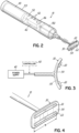
- the controller 42, power supply 40, user interface may be contained in a housing 55, 55a shaped in the form of a handle from which the eyelid contacting portion 30, 30a, 30b, 30c projects.
- the controller, power supply, user interface, and other components may be in one or more housings and the one or more housings need not be in the form of a handle.
- the housing with one or more components may be a base unit 57 that can be located some distance away from the subject but that is also electrically coupled to the eyelid contacting portion by a flexible member, such as an electric cable.
- the base unit 57 may optionally be fluidly coupled to the eyelid contacting portion by one or more flexible tubes to allow for the delivery of wash fluid, the removal of waste fluid, and combinations thereof for eyelid contacting portion having such functionality.
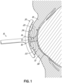
- an embodiment of the device 10 for treating an ocular disorder includes an eye contacting portion 30 with a surface 54 that includes a first electrode 20 and a second electrode 22.
- the surface 54 of the eye contacting portion 30 may be curved to generally correspond to the external curvature of the eye and in particular, the curvature of the upper and lower eyelids 18, 19 so that the first electrode 20 may make contact across the outer surface of the upper eyelid 18 and the second electrode 22 may make contact with the outer surface of lower eyelid 19 when the eyelids 18, 19 are in a closed position.
- Each of the first and second electrodes 20, 22 has a width W that generally corresponds to the width of the each of the upper and lower eyelids 18, 19.
- each of the first and second electrodes 22, 22 has a width W that ranges from 2 cm to about 5 cm.
- One of the first electrode or second electrodes 20, 22 functions as a cathode and the other of the first electrode or second electrodes 20, 22 functions as an anode.
- the first and second electrodes 20, 22 are electrically coupled to a circuit 50 that includes a power supply 40 ( FIG. 3 ).
- electrical energy flows from the first electrode 20 through the upper eyelid 18 and the upper eyelid margin 14 to the debris 12.
- the electrical energy then passes through and disrupts the debris 12 before passing through the lower eyelid margin 16 and lower eyelid 19 to the second electrode 22.
- the electrical energy could flow in the opposite direction from the second electrode 22 to the first electrode 20 if the second electrode 22 is the anode and the first electrode is the cathode.
- an electrolyte solution may be added to the eye, such as between the upper and lower eyelid margins 14, 16, to improve the disruption of debris 12 by the electrical energy.
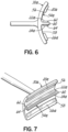
- FIGS. 5 , 6, and 7 illustrate embodiment of the eye contacting portion 30a of the device 10. 10, in accordance with the present invention.
- the surface 54a of the eye contacting portion 30a is separated into an upper portion 56 and a lower portion 58 by a shelf 60.
- the shelf 60 has an upper shelf surface 62 and a lower shelf surface 64.
- the upper portion 56 includes a first electrode 20a and the upper shelf surface 62 adjacent the upper portion 56 includes a second electrode 22a.
- One of the first or second electrodes 20a, 22a will be an anode and the other of the first or second electrodes 20a, 22a will be a cathode.
- the lower portion 58 includes a third electrode 24 and the lower shelf surface 64 includes a fourth electrode 26.
- One of the third or fourth electrodes 24, 26 will be an anode and the other of the third or fourth electrodes 24, 26 will be a cathode.
- the first, second, third, and fourth electrodes 20a, 22a, 24, 26 are electrically coupled to a circuit that includes a power supply.
- the second electrode 22a on the upper shelf surface 62 contacts the upper eyelid margin 14 of the upper eyelid 18 and may be curved to generally correspond with the curvature of the upper eyelid margin 14.
- the second electrode 22a will also contact debris 12 along the upper eyelid margin 14 of the upper eyelid 18.
- the fourth electrode 26 on the lower shelf surface 64 contacts the lower eyelid margin 16 of the lower eyelid 19 and may be curved to generally correspond with the curvature of the lower eyelid margin 16.
- the first and third electrodes 20a 24 each have a width that corresponds generally with the widths of the respective upper and lower eyelids 18, 19.
- the second and fourth electrodes 22a, 26 on the upper and lower shelf surfaces 62, 64 each have a length and a width that generally corresponds with the length and width of the respective upper and lower eyelid margins 14, 16 for the upper and lower eyelids 18.
- the widths of each of the first, second, third, and fourth electrodes 20a, 22a, 24, 26 may range between about 2 cm and about 5 cm.
- the lengths of the second and fourth electrodes may range between about 0.5 mm and 3 mm, or between about 1 mm and about 2mm.
- the second and fourth electrodes 22, 26 on the upper and lower shelf surfaces 62, 64, respectively, are anodes and the first and third electrodes 20a, 24 on the upper and lower portions 56, 58 of surface 54a are cathodes, when the device utilizes a direct current power source.
- Electrical current flows from the anodes through debris 12 on or near the upper and lower eyelid margins 14, 16 to disrupt the debris 12. The electrical current then travels through the upper and lower eyelids 18, 19 to the cathode to complete the circuit.
- the power supply which may be a battery or other source of electricity, provides electrical energy to the anodes. It will be appreciated that the polarity of the electrodes may be reversed. It will also be appreciated that an alternating current power source, which will obviate the anode cathode designation of the electrodes.
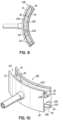
- FIGS. 8 , 9, and 10 illustrate an alternative embodiment of the eye contacting portion 30b of the device 10.
- the eye contacting portion 30b is separated into an upper channel 68 and a lower channel 70.
- the upper channel 68 is defined by an upper outer sidewall 72 and an opposite upper inner sidewall 74.
- the upper outer sidewall 72 is joined to the upper inner sidewall 74 by an upper base wall 76.
- the upper base wall 76 includes a first electrode 20b.
- One of the upper outer and upper inner sidewalls 72, 74 includes a second electrode 22b.
- both of the upper outer and upper inner sidewalls 72, 74 include an electrode, with one of the upper sidewalls including the second electrode 22b and the other upper sidewall including a third electrode 24a.
- One of the first and second electrodes 20b, 22b will be an anode and the other of the first or second electrodes 20b, 22b will be a cathode.
- the third electrode 24a will have the same polarity as the second electrode 22b. In other words, if the second electrode 22b is a cathode, the third electrode 24a will also be a cathode.
- the lower channel 70 is defined by a lower outer sidewall 80 and an opposite lower inner sidewall 82.
- the lower outer sidewall 80 is joined to the lower inner sidewall 82 by a lower base wall 84.
- the lower base wall 84 includes a first electrode 20c.
- One of the lower outer and lower inner sidewalls 80, 82 includes a second electrode 22c.
- both of the lower outer and lower inner sidewalls 80, 82 include an electrode, with one of the lower sidewalls including the second electrode 22c and the other lower sidewall including a third electrode 24b.
- One of the first and second electrodes 20c, 22c will be an anode and the other of the first or second electrodes 20c, 22c will be a cathode.
- the third electrode 24b will have the same polarity as the second electrode 22c. In other words, if the second electrode 22c is a cathode, the third electrode 24b will also be a cathode.
- the upper eyelid 18 of a subject is inserted into the upper channel 68 and the lower eyelid 19 of the subject is inserted into the lower channel 70.
- the inner surfaces 88, 90 of the respective upper and lower eyelids 18, 19 will contact electrodes located on the respective upper and lower inner sidewalls 74, 82.
- the outer surfaces 92, 94 of the respective upper and lower eyelids 18, 19 of the subject will contact electrodes that may be located on the respective upper and lower outer sidewalls 92, 94.
- the upper and lower eyelid margins 14, 16 of the respective upper and lower eyelids 18, 19, as well as debris 12 on the eyelid margins 14, 16 will contact the electrodes on the upper and lower base walls 76, 84. Electrical current will flow from the anodes through the debris and eyelid to the cathodes.
- FIGS. 8-10 may also include one or more irrigation ports 37 in the upper and lower channels in the upper and lower channels 68, 70 to remove wash solution 96 and debris from the channels and to decreases the overflow of wash fluid and debris into the eye and onto the face of the subject.
- the irrigation ports 37 may be in fluid communication with a waste fluid receptacle such as a waste fluid reservoir 45 or sink ( FIG. 8 ).
- the drained wash solution 96 may be drawn into the irrigation ports 37 by a pump, such as vacuum pump 101.
- the pump, such as vacuum pump 101 may be operated by the controller 42.
- FIGS. 11 and 12 illustrate an alternative embodiment of the device that includes upper and lower channels 68a, 70a similar to the upper and lower channels 68, 70 in the embodiment illustrated in FIGS. 8 , 9, and 10 .
- the upper and lower outer sidewalls 72a, 80a in this alternative embodiment may move relative to the upper and lower base walls 76a, 84a and upper and lower inner sidewalls 74a, 82a. This movement allows the upper and lower channels 68a, 70a to open to ease insertion of the upper and lower eyelids 18, 19 into the respective upper and lower channels 68a, 70a.
- the upper and lower outer sidewalls 72a, 80a may be move toward the upper and lower inner sidewalls 74a, 82a, such as the through a trigger 48 coupled to a mechanism for moving the upper and lower outer sidewalls 72a, 80a until the sufficient contact is made with the electrodes in the upper and lower channels 68a, 70a.
- the electrodes and nozzles 36 may be activated to remove debris 12 as discussed above with respect to the embodiment disclosed in FIGS. 8 , 9, and 10 .
- FIGS. 8-12 are shown as having upper and lower channels 68, 68a, 70, 70a, it will be appreciated that embodiments of the device 10 and 10a may be made with a single channel to allow for treatment of one eyelid at a time.
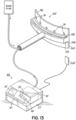
- FIG. 13 illustrates an alternative embodiment of the eyelid contacting portion 30d of the device 10b. 10b, according to the present invention.
- upper and lower inner side walls 74b and 82b are separated by shelf having upper and lower base walls 76b and 84b.
- the eyelid connecting portion 30d is configured to be positioned such that the upper and lower inner side walls 74b and 82b are placed between the inner surface of the eyelid and the outer surface of the eyeball.
- An electrode 20b such as an anode
- another electrode 20c such as another anode
- the electrodes 20b, 20c on the eyelid contacting portion 30d are electrically coupled to a base unit 57 by a flexible member, such as an electric cable.
- a flexible member such as an electric cable.
- the flexible member projects from the shelf such that, during use, the flexible member projects between the upper and lower eyelids of the subject.
- This embodiment also utilizes another electrode 22d that is separate from the eyelid contacting portion 30d.
- this electrode will have an opposite polarity from the polarity of the electrodes 20b, 20c on the eyelid contacting portion 30d.
- the electrodes 20b, 20c on the eyelid contacting portion 30d are anodes and the electrode 22d is a cathode.
- the electrodes 20b, 20c on the eyelid contacting portion 30d are cathodes and the electrode 22d is an anode.
- the electrode 22d may include an electrolyte, such as an electrolytic gel, an adhesive, or an electrolytic adhesive to improve contact with the skin. Electrodes as are known in the art may be utilized for this purpose.
- the electrode 22d is electrically coupled to the base 57 with an electric cable. During use, the electrode 22d is position adjacent the eye being treated with the eyelid contacting portion 30d. In an embodiment, the electrode 22d is position between 1 inch and 2 inches from margin of the lower eyelid. In an embodiment, the electrode is position below the eye being treated. In another embodiment, the electrode 22d is position lateral to the eye being treated. In another embodiment, the electrode 22d is position above the eye being treated.
- the electrodes may be made from materials as are known in the art for transmitting electrical energy to the surfaces of the skin.
- the electrodes can be made of a number of materials, such as metals, carbon graphite electrodes, and electrically conducting rubber sheets.
- Exemplary metals include gold, silver, and other biologically tolerated metals and alloys thereof.
- Embodiments of the invention utilize only electrical energy to disrupt debris without utilizing other forms of energy to result in debris disruption.
- alternative embodiments may utilize electrical energy to disrupt debris in combination with a wash fluid to assist with debris disruption, to remove debris, or both to disrupt and remove debris.
- Another embodiment of the invention may include an ultrasonic driver 102 coupled to the eyelid contacting portion to induce ultrasonic movement of an eyelid contacting portion ( FIGS. 2 and 11 ).
- Embodiments of the invention will utilize the ultrasonic driver 102 in combination with electrical energy applied through electrodes to disrupt debris. Accordingly, these devices will include electrodes, as described above as well as an ultrasonic driver.
- Other embodiments of the invention will utilize only the ultrasonic driver 102 to induce ultrasonic movement of the eyelid contacting portion to disrupt debris without applying electrical energy to the eye through electrodes to disrupt debris. Accordingly, these embodiments of the device will have an ultrasonic driver but will lack electrodes.
- inventions utilizing an ultrasonic driver 102 may optionally utilize a wash fluid delivered through nozzles 36 to assist with disrupting, removing, or both disrupting and removing debris.
- embodiments of the device utilizing a wash fluid will include nozzles, a reservoir, and pump, as previously described. These embodiments may also optionally utilize irrigation ports 37 to remove fluids, such as waste fluid and debris, during use. Accordingly, embodiments of the device may include irrigation ports 37 coupled to a pump, such as a vacuum pump. The waste fluid may optionally be pumped to a reservoir or to a waste receptacle, such as a sink.
- the eyelid contacting portion is brought into contact with the external portion of the upper eyelid, the external portion of the lower eyelid, the upper eyelid margin between the external surface of the upper eyelid and the internal surface of the upper eyelid, the lower eyelid margin between the external surface of the lower eyelid and the internal surface of the lower eyelid, the internal surface of the upper eyelid, the internal surface of the lower eyelid or combinations thereof. It is further appreciated that the eyelid contacting portion simultaneously contacts the relevant portion of the eyelid as described in the previous sentence across at least fifty percent of the width of the eyelid. In another embodiment, the eyelid contacting portion contacting portion contacts the relevant portion of the eyelid across at least seventy five percent of the width of the eyelid.
- the eyelid contacting portion contacting portion contacts the relevant portion of the eyelid across at least ninety percent of the width of the eyelid.
- the width of the eyelid being defined as the portion of either the upper or lower eyelid that extends between the medial commissure and the lateral commissure.
- the ultrasonic driver 102 is activated and ultrasonic energy is applied to the at least one of the eyelid surfaces as well as to debris located thereon by the eyelid contacting portion.
- ultrasonic energy is applied without the application of any other form of energy to disrupt debris.
- the ultrasonic energy is applied in combination with another form of energy to disrupt debris.
- ultrasonic energy may be applied in combination with electrical energy to disrupt debris.
- the ultrasonic energy may be applied at the same time as the other form of energy, such as electrical energy.
- the ultrasonic energy and the other form of energy, such as electrical energy are not applied at the same time.
- ultrasonic energy and the other form of energy, such as electrical energy may be applied in an alternating manner, or one of these forms of energy may be applied first and the other form of energy may be applied second. This alternating pattern may be repeated.
- the other form of energy such as electrical energy
- the ultrasonic energy is applied first and the ultrasonic energy is applied second.
- the ultrasonic energy is applied first and the other form of energy, such as electrical energy, is applied second.
- the ultrasonic energy is applied for a duration and at a frequency sufficient to disrupt debris on the eyelid, and in particular debris on the eyelid margin.
- each of the electrodes could be replaced with a plurality of smaller electrodes space apart so as to apply electrical energy sufficient to disrupt debris on the eyelid margin.
- exemplary embodiments of the invention have been illustrated or described as utilizing direct current. Alternative embodiments of the inventions described herein may utilize alternating current.
Landscapes
- Health & Medical Sciences (AREA)
- Engineering & Computer Science (AREA)
- Life Sciences & Earth Sciences (AREA)
- Surgery (AREA)
- Ophthalmology & Optometry (AREA)
- Animal Behavior & Ethology (AREA)
- Heart & Thoracic Surgery (AREA)
- Nuclear Medicine, Radiotherapy & Molecular Imaging (AREA)
- General Health & Medical Sciences (AREA)
- Public Health (AREA)
- Veterinary Medicine (AREA)
- Biomedical Technology (AREA)
- Vascular Medicine (AREA)
- Medical Informatics (AREA)
- Molecular Biology (AREA)
- Physics & Mathematics (AREA)
- Otolaryngology (AREA)
- Plasma & Fusion (AREA)
- Plastic & Reconstructive Surgery (AREA)
- Dentistry (AREA)
- Mechanical Engineering (AREA)
- Electrotherapy Devices (AREA)
Claims (10)
- Augenlid-berührender Teil, der zum Koppeln mit einem Vorrichtungsgehäuse zum Entfernen von Ablagerungen von einem Augenlidrand konfiguriert ist, wobei der Augenlid-berührende Teil umfasst:
einen Auge-berührenden Teil (30), der eine erste Oberfläche (54) aufweist, die gekrümmt ist, um einer Krümmung des oberen und des unteren Augenlids eines Auges zu entsprechen, wobei der Auge-berührende Teil (30) dadurch gekennzeichnet ist, dass er aufweist:einen Vorsprung (60) an der ersten Oberfläche (54), der die erste Oberfläche in einen oberen Teil (56) und einen unteren Teil (58) unterteilt;eine erste Elektrode (20, 22, 24, 26), die sich am oberen Teil befindet; undeine zweite Elektrode (20, 22, 24, 26), die sich am unteren Teil befindet und von der ersten Elektrode beabstandet ist, wobei mindesten eine von den ersten und zweiten Elektroden (20, 22, 24, 26) elektrisch mit einem elektrischen Kontakt gekoppelt ist, der zum Zusammenpassen mit einem weiteren elektrischen Kontakt am Vorrichtungsgehäuse konfiguriert ist. - Vorrichtung nach Anspruch 1, ferner umfassend:
eine dritte Elektrode an einer oberen Oberfläche (62) des Vorsprungs (60) und eine vierte Elektrode an einer unteren Oberfläche (64) des Vorsprungs (60), wobei die erste, zweite, dritte und vierte Elektrode (20, 22, 24, 26) mit einem elektrischen Kontakt gekoppelt sind, der zum Zusammenpassen mit einem entsprechenden elektrischen Kontakt am Vorrichtungsgehäuse konfiguriert ist. - Vorrichtung nach Anspruch 1, die ferner eine dritte Elektrode (22d) umfasst, die von dem Auge-berührenden Teil (30d) separat ist.
- Vorrichtung nach Anspruch 1, ferner umfassend:einen Ultraschall-Treiber, der mit dem genannten Augenlid-berührenden Teil (30) gekoppelt ist,wobei die erste Oberfläche (54) des Augenlid-berührenden Teils zum Berühren eines Teils des Augenlids über mindestens fünfzig Prozent der Breite des Augenlids konfiguriert ist undwobei der Teil des Augenlids aus der Gruppe bestehend aus einem äußeren Teil eines oberen Augenlids, einem äußeren Teil eines unteren Augenlids, einem oberen Augenlidrand zwischen der Außenfläche des oberen Augenlids und einer Innenfläche des oberen Augenlids, einem unteren Augenlidrand zwischen der Außenfläche des unteren Augenlids und einer Innenfläche des unteren Augenlids, der Innenfläche des oberen Augenlids, der Innenfläche des unteren Augenlids oder Kombinationen davon ausgewählt ist.
- Vorrichtung nach einem der vorhergehenden Ansprüche, ferner umfassend:
eine Stromversorgung, wobei mindestens eine der ersten und zweiten Elektroden (20, 22, 24, 26) elektrisch mit der Stromversorgung gekoppelt ist. - Vorrichtung nach einem der vorhergehenden Ansprüche, ferner umfassend:mindestens eine Düse (36) undeinen Behälter (75), wobei die mindestens eine Düse (36) in Fluidverbindung mit dem Behälter (75) ist.
- Vorrichtung nach Anspruch 6, ferner umfassend:mindestens eine Spülöffnung (37) undeine Pumpe (100), wobei die Pumpe (100) in Fluidverbindung mit der Spülöffnung (37) ist.
- Vorrichtung nach einem der vorhergehenden Ansprüche, die ferner einen Ultraschall-Treiber (102) umfasst, der mit dem Augenlid-berührenden Teil (30) gekoppelt ist.
- Vorrichtung nach einem der vorhergehenden Ansprüche, wobei die Elektroden (20, 22, 24, 26) zum Anwenden einer Spannung zwischen etwa 0,1 Volt und 20 Volt auf die Augenlider konfiguriert sind.
- Vorrichtung nach einem der vorhergehenden Ansprüche, wobei die Elektroden (20, 22, 24, 26) zum Anwenden eines Stroms von weniger als etwa 3 Milliampere auf die Augenlider konfiguriert sind.
Applications Claiming Priority (2)
| Application Number | Priority Date | Filing Date | Title |
|---|---|---|---|
| US201562242721P | 2015-10-16 | 2015-10-16 | |
| PCT/US2016/057112 WO2017066620A1 (en) | 2015-10-16 | 2016-10-14 | Energetic device for treating an eye disorder |
Publications (3)
| Publication Number | Publication Date |
|---|---|
| EP3362013A1 EP3362013A1 (de) | 2018-08-22 |
| EP3362013B1 true EP3362013B1 (de) | 2024-12-04 |
| EP3362013C0 EP3362013C0 (de) | 2024-12-04 |
Family
ID=57233856
Family Applications (1)
| Application Number | Title | Priority Date | Filing Date |
|---|---|---|---|
| EP16791160.1A Active EP3362013B1 (de) | 2015-10-16 | 2016-10-14 | Energetische vorrichtung zur behandlung einer augenerkrankung |
Country Status (3)
| Country | Link |
|---|---|
| US (2) | US11819456B2 (de) |
| EP (1) | EP3362013B1 (de) |
| WO (1) | WO2017066620A1 (de) |
Families Citing this family (15)
| Publication number | Priority date | Publication date | Assignee | Title |
|---|---|---|---|---|
| US20180001107A1 (en) | 2016-07-01 | 2018-01-04 | Btl Holdings Limited | Aesthetic method of biological structure treatment by magnetic field |
| ES3015111T3 (en) | 2015-09-15 | 2025-04-29 | I Lumen Scient Inc | Ocular microcurrent stimulation therapy apparatus |
| WO2017066620A1 (en) | 2015-10-16 | 2017-04-20 | Rynerson James M | Energetic device for treating an eye disorder |
| US11534619B2 (en) | 2016-05-10 | 2022-12-27 | Btl Medical Solutions A.S. | Aesthetic method of biological structure treatment by magnetic field |
| US11141219B1 (en) | 2016-08-16 | 2021-10-12 | BTL Healthcare Technologies, a.s. | Self-operating belt |
| US10898370B2 (en) | 2018-05-21 | 2021-01-26 | Thomas Conti | Eyelid cleaning tool |
| EP3897817B1 (de) | 2018-12-20 | 2023-08-30 | i-LUMEN Scientific, Inc. | System zur mikrostrom-stimulationstherapie |
| CN113382708A (zh) * | 2019-01-29 | 2021-09-10 | 詹姆斯·M·瑞纳森 | 杂屑去除装置及方法 |
| US12156689B2 (en) | 2019-04-11 | 2024-12-03 | Btl Medical Solutions A.S. | Methods and devices for aesthetic treatment of biological structures by radiofrequency and magnetic energy |
| EP4066887B1 (de) | 2019-04-11 | 2023-11-01 | BTL Medical Solutions a.s. | Vorrichtungen zur ästhetischen behandlung biologischer strukturen durch hochfrequenz und magnetische energie |
| KR200498115Y1 (ko) | 2020-05-04 | 2024-07-03 | 비티엘 헬쓰케어 테크놀로지스 에이.에스. | 환자의 미용 시술을 위한 디바이스 |
| US11878167B2 (en) | 2020-05-04 | 2024-01-23 | Btl Healthcare Technologies A.S. | Device and method for unattended treatment of a patient |
| CN113599061B (zh) * | 2021-10-08 | 2021-12-21 | 南方医科大学深圳医院 | 睑板腺功能障碍治疗装置 |
| WO2023062563A1 (en) | 2021-10-13 | 2023-04-20 | Btl Medical Solutions A.S. | Devices for aesthetic treatment of biological structures by radiofrequency and magnetic energy |
| US11896816B2 (en) | 2021-11-03 | 2024-02-13 | Btl Healthcare Technologies A.S. | Device and method for unattended treatment of a patient |
Citations (1)
| Publication number | Priority date | Publication date | Assignee | Title |
|---|---|---|---|---|
| WO2014179356A1 (en) * | 2013-04-30 | 2014-11-06 | Tear Film Innovations Llc | Systems and methods for the treatment of eye conditions |
Family Cites Families (23)
| Publication number | Priority date | Publication date | Assignee | Title |
|---|---|---|---|---|
| US4326529A (en) * | 1978-05-26 | 1982-04-27 | The United States Of America As Represented By The United States Department Of Energy | Corneal-shaping electrode |
| US4406658A (en) * | 1981-03-06 | 1983-09-27 | Medtronic, Inc. | Iontophoretic device with reversible polarity |
| US4955378A (en) * | 1988-05-02 | 1990-09-11 | University Of South Florida | Apparatus and methods for performing electrofusion at specific anatomical sites |
| US5462521A (en) * | 1993-12-21 | 1995-10-31 | Angeion Corporation | Fluid cooled and perfused tip for a catheter |
| ES2129803T3 (es) * | 1993-12-22 | 1999-06-16 | Sulzer Osypka Gmbh | Cateter de ablacion cardiaca marcado ultrasonicamente. |
| US5843147A (en) * | 1996-04-30 | 1998-12-01 | Medtronic, Inc. | Implantable eyelid electrode and method of implanting same |
| US6035236A (en) * | 1998-07-13 | 2000-03-07 | Bionergy Therapeutics, Inc. | Methods and apparatus for electrical microcurrent stimulation therapy |
| EP1207788A4 (de) * | 1999-07-19 | 2009-12-09 | St Jude Medical Atrial Fibrill | Gerät und verfahren zur ablation von gewebe |
| US20050004625A1 (en) * | 2001-06-29 | 2005-01-06 | Chow Alan Y. | Treatment of degenerative retinal disease via electrical stimulation of surface structures |
| JP4685786B2 (ja) * | 2003-06-10 | 2011-05-18 | ネオメディックス コーポレイション | ヒト患者又は罹患動物の組織を切断又は切除するための機器 |
| US7480530B2 (en) | 2003-06-30 | 2009-01-20 | Johnson & Johnson Consumer Companies, Inc. | Device for treatment of barrier membranes |
| WO2013003594A2 (en) * | 2011-06-28 | 2013-01-03 | Tearscience, Inc. | Methods and systems for treating meibomian gland dysfunction using radio-frequency energy |
| US8409189B2 (en) * | 2008-01-23 | 2013-04-02 | Avedro, Inc. | System and method for reshaping an eye feature |
| CA2722296A1 (en) * | 2008-04-29 | 2009-11-05 | Virginia Tech Intellectual Properties, Inc. | Irreversible electroporation to create tissue scaffolds |
| US9204925B2 (en) * | 2008-08-14 | 2015-12-08 | The Cleveland Clinic Foundation | Apparatus and method for treating a neuromuscular defect |
| NO2490635T3 (de) * | 2009-10-23 | 2018-02-03 | ||
| JPWO2011089718A1 (ja) * | 2010-01-22 | 2013-05-20 | オリンパスメディカルシステムズ株式会社 | 治療用処置具、治療用処置装置および治療処置方法 |
| US9662169B2 (en) * | 2011-07-30 | 2017-05-30 | Biosense Webster (Israel) Ltd. | Catheter with flow balancing valve |
| US9039718B2 (en) * | 2012-07-24 | 2015-05-26 | Blephex, Llc | Method and device for treating an ocular disorder |
| CA2873219C (en) * | 2012-07-24 | 2019-04-02 | Blephex, Llc | Device for treating an ocular disorder |
| US20150216722A1 (en) * | 2014-02-06 | 2015-08-06 | John R. CHOATE | Method and apparatus for ultrasonic eye cleaner |
| US20160346029A1 (en) * | 2015-02-06 | 2016-12-01 | Steven D. Colquhoun | Electrocautery device |
| WO2017066620A1 (en) | 2015-10-16 | 2017-04-20 | Rynerson James M | Energetic device for treating an eye disorder |
-
2016
- 2016-10-14 WO PCT/US2016/057112 patent/WO2017066620A1/en not_active Ceased
- 2016-10-14 EP EP16791160.1A patent/EP3362013B1/de active Active
-
2018
- 2018-04-16 US US15/953,616 patent/US11819456B2/en active Active
-
2023
- 2023-10-03 US US18/480,253 patent/US12193974B2/en active Active
Patent Citations (1)
| Publication number | Priority date | Publication date | Assignee | Title |
|---|---|---|---|---|
| WO2014179356A1 (en) * | 2013-04-30 | 2014-11-06 | Tear Film Innovations Llc | Systems and methods for the treatment of eye conditions |
Also Published As
| Publication number | Publication date |
|---|---|
| US12193974B2 (en) | 2025-01-14 |
| EP3362013A1 (de) | 2018-08-22 |
| US20240065889A1 (en) | 2024-02-29 |
| US11819456B2 (en) | 2023-11-21 |
| US20180325729A1 (en) | 2018-11-15 |
| WO2017066620A1 (en) | 2017-04-20 |
| EP3362013C0 (de) | 2024-12-04 |
Similar Documents
| Publication | Publication Date | Title |
|---|---|---|
| EP3362013B1 (de) | Energetische vorrichtung zur behandlung einer augenerkrankung | |
| US12290473B2 (en) | Method and device for treating an ocular disorder | |
| US9039718B2 (en) | Method and device for treating an ocular disorder | |
| US20160367795A1 (en) | Nasal stimulation devices and methods | |
| US20150216722A1 (en) | Method and apparatus for ultrasonic eye cleaner | |
| US20140214062A1 (en) | Method and device for treating an ocular disorder | |
| US20250134709A1 (en) | Electrolytic device for treating an eye disorder | |
| US20200093638A1 (en) | Instruments For Removing Debris From An Eye | |
| HK1247549A1 (en) | Instruments for removing debris from an eye | |
| CN214968772U (zh) | 一种眼科治疗用睑板按摩器 | |
| JP6614577B2 (ja) | マイボーム腺の閉塞を予防又は治療する眼瞼縁清拭具 | |
| HK1227274A1 (en) | Instruments for removing debris from an eye | |
| HK1210691B (en) | Device for treating an ocular disorder |
Legal Events
| Date | Code | Title | Description |
|---|---|---|---|
| STAA | Information on the status of an ep patent application or granted ep patent |
Free format text: STATUS: UNKNOWN |
|
| STAA | Information on the status of an ep patent application or granted ep patent |
Free format text: STATUS: THE INTERNATIONAL PUBLICATION HAS BEEN MADE |
|
| PUAI | Public reference made under article 153(3) epc to a published international application that has entered the european phase |
Free format text: ORIGINAL CODE: 0009012 |
|
| STAA | Information on the status of an ep patent application or granted ep patent |
Free format text: STATUS: REQUEST FOR EXAMINATION WAS MADE |
|
| 17P | Request for examination filed |
Effective date: 20180501 |
|
| AK | Designated contracting states |
Kind code of ref document: A1 Designated state(s): AL AT BE BG CH CY CZ DE DK EE ES FI FR GB GR HR HU IE IS IT LI LT LU LV MC MK MT NL NO PL PT RO RS SE SI SK SM TR |
|
| AX | Request for extension of the european patent |
Extension state: BA ME |
|
| DAV | Request for validation of the european patent (deleted) | ||
| DAX | Request for extension of the european patent (deleted) | ||
| STAA | Information on the status of an ep patent application or granted ep patent |
Free format text: STATUS: EXAMINATION IS IN PROGRESS |
|
| 17Q | First examination report despatched |
Effective date: 20210311 |
|
| P01 | Opt-out of the competence of the unified patent court (upc) registered |
Effective date: 20230530 |
|
| GRAP | Despatch of communication of intention to grant a patent |
Free format text: ORIGINAL CODE: EPIDOSNIGR1 |
|
| STAA | Information on the status of an ep patent application or granted ep patent |
Free format text: STATUS: GRANT OF PATENT IS INTENDED |
|
| INTG | Intention to grant announced |
Effective date: 20240617 |
|
| GRAS | Grant fee paid |
Free format text: ORIGINAL CODE: EPIDOSNIGR3 |
|
| GRAA | (expected) grant |
Free format text: ORIGINAL CODE: 0009210 |
|
| STAA | Information on the status of an ep patent application or granted ep patent |
Free format text: STATUS: THE PATENT HAS BEEN GRANTED |
|
| AK | Designated contracting states |
Kind code of ref document: B1 Designated state(s): AL AT BE BG CH CY CZ DE DK EE ES FI FR GB GR HR HU IE IS IT LI LT LU LV MC MK MT NL NO PL PT RO RS SE SI SK SM TR |
|
| REG | Reference to a national code |
Ref country code: GB Ref legal event code: FG4D |
|
| REG | Reference to a national code |
Ref country code: CH Ref legal event code: EP |
|
| REG | Reference to a national code |
Ref country code: DE Ref legal event code: R096 Ref document number: 602016090514 Country of ref document: DE |
|
| REG | Reference to a national code |
Ref country code: IE Ref legal event code: FG4D |
|
| U01 | Request for unitary effect filed |
Effective date: 20241204 |
|
| P04 | Withdrawal of opt-out of the competence of the unified patent court (upc) registered |
Free format text: CASE NUMBER: APP_65076/2024 Effective date: 20241209 |
|
| U07 | Unitary effect registered |
Designated state(s): AT BE BG DE DK EE FI FR IT LT LU LV MT NL PT RO SE SI Effective date: 20241212 |
|
| PG25 | Lapsed in a contracting state [announced via postgrant information from national office to epo] |
Ref country code: HR Free format text: LAPSE BECAUSE OF FAILURE TO SUBMIT A TRANSLATION OF THE DESCRIPTION OR TO PAY THE FEE WITHIN THE PRESCRIBED TIME-LIMIT Effective date: 20241204 |
|
| PG25 | Lapsed in a contracting state [announced via postgrant information from national office to epo] |
Ref country code: ES Free format text: LAPSE BECAUSE OF FAILURE TO SUBMIT A TRANSLATION OF THE DESCRIPTION OR TO PAY THE FEE WITHIN THE PRESCRIBED TIME-LIMIT Effective date: 20241204 |
|
| PG25 | Lapsed in a contracting state [announced via postgrant information from national office to epo] |
Ref country code: NO Free format text: LAPSE BECAUSE OF FAILURE TO SUBMIT A TRANSLATION OF THE DESCRIPTION OR TO PAY THE FEE WITHIN THE PRESCRIBED TIME-LIMIT Effective date: 20250304 |
|
| PG25 | Lapsed in a contracting state [announced via postgrant information from national office to epo] |
Ref country code: GR Free format text: LAPSE BECAUSE OF FAILURE TO SUBMIT A TRANSLATION OF THE DESCRIPTION OR TO PAY THE FEE WITHIN THE PRESCRIBED TIME-LIMIT Effective date: 20250305 |
|
| PG25 | Lapsed in a contracting state [announced via postgrant information from national office to epo] |
Ref country code: RS Free format text: LAPSE BECAUSE OF FAILURE TO SUBMIT A TRANSLATION OF THE DESCRIPTION OR TO PAY THE FEE WITHIN THE PRESCRIBED TIME-LIMIT Effective date: 20250304 |
|
| PG25 | Lapsed in a contracting state [announced via postgrant information from national office to epo] |
Ref country code: SM Free format text: LAPSE BECAUSE OF FAILURE TO SUBMIT A TRANSLATION OF THE DESCRIPTION OR TO PAY THE FEE WITHIN THE PRESCRIBED TIME-LIMIT Effective date: 20241204 |
|
| PG25 | Lapsed in a contracting state [announced via postgrant information from national office to epo] |
Ref country code: PL Free format text: LAPSE BECAUSE OF FAILURE TO SUBMIT A TRANSLATION OF THE DESCRIPTION OR TO PAY THE FEE WITHIN THE PRESCRIBED TIME-LIMIT Effective date: 20241204 |
|
| PG25 | Lapsed in a contracting state [announced via postgrant information from national office to epo] |
Ref country code: IS Free format text: LAPSE BECAUSE OF FAILURE TO SUBMIT A TRANSLATION OF THE DESCRIPTION OR TO PAY THE FEE WITHIN THE PRESCRIBED TIME-LIMIT Effective date: 20250404 |
|
| PG25 | Lapsed in a contracting state [announced via postgrant information from national office to epo] |
Ref country code: SK Free format text: LAPSE BECAUSE OF FAILURE TO SUBMIT A TRANSLATION OF THE DESCRIPTION OR TO PAY THE FEE WITHIN THE PRESCRIBED TIME-LIMIT Effective date: 20241204 |
|
| PG25 | Lapsed in a contracting state [announced via postgrant information from national office to epo] |
Ref country code: CZ Free format text: LAPSE BECAUSE OF FAILURE TO SUBMIT A TRANSLATION OF THE DESCRIPTION OR TO PAY THE FEE WITHIN THE PRESCRIBED TIME-LIMIT Effective date: 20241204 |
|
| PLBE | No opposition filed within time limit |
Free format text: ORIGINAL CODE: 0009261 |
|
| STAA | Information on the status of an ep patent application or granted ep patent |
Free format text: STATUS: NO OPPOSITION FILED WITHIN TIME LIMIT |
|
| 26N | No opposition filed |
Effective date: 20250905 |