EP3361847A1 - A heat exchanger - Google Patents
A heat exchanger Download PDFInfo
- Publication number
- EP3361847A1 EP3361847A1 EP17155992.5A EP17155992A EP3361847A1 EP 3361847 A1 EP3361847 A1 EP 3361847A1 EP 17155992 A EP17155992 A EP 17155992A EP 3361847 A1 EP3361847 A1 EP 3361847A1
- Authority
- EP
- European Patent Office
- Prior art keywords
- heat
- channels
- heat exchanger
- output section
- section
- Prior art date
- Legal status (The legal status is an assumption and is not a legal conclusion. Google has not performed a legal analysis and makes no representation as to the accuracy of the status listed.)
- Granted
Links
Images


Classifications
-
- H—ELECTRICITY
- H05—ELECTRIC TECHNIQUES NOT OTHERWISE PROVIDED FOR
- H05K—PRINTED CIRCUITS; CASINGS OR CONSTRUCTIONAL DETAILS OF ELECTRIC APPARATUS; MANUFACTURE OF ASSEMBLAGES OF ELECTRICAL COMPONENTS
- H05K7/00—Constructional details common to different types of electric apparatus
- H05K7/20—Modifications to facilitate cooling, ventilating, or heating
- H05K7/2089—Modifications to facilitate cooling, ventilating, or heating for power electronics, e.g. for inverters for controlling motor
- H05K7/20936—Liquid coolant with phase change
-
- F—MECHANICAL ENGINEERING; LIGHTING; HEATING; WEAPONS; BLASTING
- F28—HEAT EXCHANGE IN GENERAL
- F28D—HEAT-EXCHANGE APPARATUS, NOT PROVIDED FOR IN ANOTHER SUBCLASS, IN WHICH THE HEAT-EXCHANGE MEDIA DO NOT COME INTO DIRECT CONTACT
- F28D15/00—Heat-exchange apparatus with the intermediate heat-transfer medium in closed tubes passing into or through the conduit walls ; Heat-exchange apparatus employing intermediate heat-transfer medium or bodies
- F28D15/02—Heat-exchange apparatus with the intermediate heat-transfer medium in closed tubes passing into or through the conduit walls ; Heat-exchange apparatus employing intermediate heat-transfer medium or bodies in which the medium condenses and evaporates, e.g. heat pipes
- F28D15/0275—Arrangements for coupling heat-pipes together or with other structures, e.g. with base blocks; Heat pipe cores
-
- H—ELECTRICITY
- H05—ELECTRIC TECHNIQUES NOT OTHERWISE PROVIDED FOR
- H05K—PRINTED CIRCUITS; CASINGS OR CONSTRUCTIONAL DETAILS OF ELECTRIC APPARATUS; MANUFACTURE OF ASSEMBLAGES OF ELECTRICAL COMPONENTS
- H05K7/00—Constructional details common to different types of electric apparatus
- H05K7/20—Modifications to facilitate cooling, ventilating, or heating
- H05K7/2029—Modifications to facilitate cooling, ventilating, or heating using a liquid coolant with phase change in electronic enclosures
- H05K7/20336—Heat pipes, e.g. wicks or capillary pumps
-
- H—ELECTRICITY
- H10—SEMICONDUCTOR DEVICES; ELECTRIC SOLID-STATE DEVICES NOT OTHERWISE PROVIDED FOR
- H10W—GENERIC PACKAGES, INTERCONNECTIONS, CONNECTORS OR OTHER CONSTRUCTIONAL DETAILS OF DEVICES COVERED BY CLASS H10
- H10W40/00—Arrangements for thermal protection or thermal control
- H10W40/70—Fillings or auxiliary members in containers or in encapsulations for thermal protection or control
- H10W40/73—Fillings or auxiliary members in containers or in encapsulations for thermal protection or control for cooling by change of state
Definitions
- the invention relates to a heat exchanger, and particularly to a heat exchanger comprising a plurality channels which are capillary dimensioned for a working fluid.
- the compact size of power electric components demands also a compact size cooling system to fully utilize the obtained space savings in the components.
- the thermal environment where the power electronic component is to operate sets limits to the cooling system. Even if the thermal environment is relatively stable the temperature of the available cooling media may be high.
- An object of the present invention is to solve the above mentioned drawbacks.
- the objects of the invention are achieved by a heat exchanger which is characterized by what is stated in the independent claim.
- the preferred embodiments of the invention are disclosed in the dependent claims.
- a heat exchanger comprising a heat input section and a heat output section, and the heat input section and the heat output section containing a working fluid in a plurality of channels.
- the plurality of channels providing a flow path for the working fluid to move between the heat input section and the heat output section.
- the plurality of channels being capillary dimensioned for the working fluid.
- the heat output section comprises a cooling liquid chamber and an inlet and an outlet for cooling liquid.
- the heat exchanger comprises two heat output sections arranged on the first end and the second end of the heat input section. The plurality of channels extend from the first heat output section through the heat input section to the second heat output section.
- the invented heat exchanger provides a safe and reliable cooling system in a compact size which operates also on higher cooling liquid temperatures.
- FIG. 1 is a perspective view of a heat exchanger 1.
- the heat exchanger 1 comprises a heat input section 2 and two heat output sections 3a-b.
- the heat input section 2 and the heat output sections 3a-b comprise a plurality of channels 4.
- the plurality of channels 4 contain a working fluid 5 and provide a flow path for the working fluid 5 to move between the heat input section 2 and the heat output sections 3a-b.
- the plurality of channels 4 are capillary dimensioned for the working fluid 5.
- the first 3a and second 3b heat output sections comprise a cooling liquid chamber 6.
- the liquid cooling chamber 6 comprises an inlet 7 and an outlet 8 for cooling liquid.
- the first heat output section 3a and the second heat output section 3b are arranged on the first end 9a and the second end 9b of the heat input section 2.
- the plurality of channels 4 extend from the first heat output section 3a through the heat input section 2 to the second heat output section 3b.
- the plurality of channels 4 have capillary dimensions.
- the plurality of channels 4 are capillary-sized, in which case they have a size small enough so that bubbles can grow uniquely in a longitudinal direction, i.e. in the longitudinal direction of the channel as opposed to the radial direction, and thereby create a pulsating effect by pushing the working liquid 5.
- the diameter of a channel which is considered capillary depends on the working fluid 5 that is used and is boiling inside the channel.
- working fluids suitable for use in the heat exchanger are R134a (Tetrafluoroethane), R145fa and R1234ze (Tetrafluoropropene) and the respective diameter of the channel varies between 1 to 3 mm.
- the plurality of channels 4 may be produced by dividing pipes into channels by internal walls of the pipes. Thus, each pipe contains several channels.
- the pipes or tubes may be Multi Port Extruded pipes, for instance.
- the inlet 7 and the outlet 8 for cooling liquid may be arranged at opposite walls of the cooling liquid chamber 6 as shown in Figures 1-2 .
- the plurality of channels 4 in the heat output section 3a-b can be arranged between the inlet 7 and outlet 8 so that the flow direction of the working fluid 5 in the plurality of channels 4 is transverse to the flow direction of the cooling liquid 10 flow.
- the cooling liquid 10 is shown with thin arrows in Figures 1-2 .
- the heat output section 3a-b operates then as a cross flow heat exchanger.
- a pump may be used for moving the cooling liquid 10.
- the cooling liquid 10 can circulate in a closed loop where it transfers the heat received in the heat output section 3a-b to another media.
- the heat input section 2 may comprise a base plate 11 as shown in Figures 1-2 and 6-8 .
- the base plate 11 comprises a first surface 12 for receiving electronic components 13.
- a second surface 14 contacts walls of the plurality of channels 4 in order to transfer heat generated by the electronic components 13 to the working fluid 5 in the plurality of channels 4. The heat is conducted from the base plate 11 to the plurality of channels 4 containing the working fluid 5.
- the second surface 14 may comprise grooves into which the plurality of channels 4 can be arranged.
- the base plate 11 can basically consists of a block of a material with a good heat conductivity. Suitable materials include metals, such as aluminium, for instance. The same material or another material with good heat conductivity may be used for the plurality of channels 4.
- the heat to the heat input section 2 is provided by electronic components 13.
- Electronic components 13 are often designed to dissipate the excess heat mainly via the electronic component's base plate.
- the electronic component's base plate is arranged in a good thermal connection with the heat input section 13 of the heat exchanger 1.
- An example of an electronic component 13 is an IGBT module of a power converter.
- FIG. 2 shows a side view of a cross section of a heat exchanger 1.
- the plurality of channels 4 in the heat output sections 3a-b may comprise fins 15 extending from the outer surface of the plurality of channels 4.
- the cooling liquid 10 flows between the fins 15.
- the fins 15 increase the heat transfer surface of the heat output section 3a-b but the fins 15 unavoidably increase the pressure drop and consequently increase the cooling liquid 10 pump power requirements to overcome the flow resistance in the heat output section 3a-b.
- the created back pressure is relatively low.
- the cooling liquid chamber 6 preferably surrounds the plurality of channels 4 in the heat output section 3a-b providing a leak tight envelope. As a reliable construction is required a friction stir welding can be used to join the cooling liquid chamber 6 and the heat output section 3a-b.
- the cooling liquid chamber 6 may comprise such a volume that the plurality of channels 4 in the heat output section 3a-b are immersed in a cooling liquid 10.
- the working fluid 5 is transported by means of differential pressure across liquid slugs and vapour slugs from the heat input section 2 to the heat output sections 3a-b and back from the heat output sections 3a-b to the heat input section 2.
- the Pulsating Heat Pipe involving a plurality of channels 4 having capillary dimensions, oscillations occur in a small channel loop heat pipe due to the bidirectional expansion of vapour inside the channels.
- the liquid slugs and elongated vapour bubbles will oscillate between a cold region, i.e. the heat output section 3a-b, and a hot region, i.e.
- the heat input section 2 because of hydrodynamic instabilities caused by the rapid expansion of the bubbles confined in the small channels, and thus provide a fluid velocity almost independent of gravity. Consequently, the heat exchanger 1 works in any orientation, without significant additional costs, and with a working fluid 5 volume that is smaller than in a conventional cooler, for instance in a liquid cold plate.
- the heat flow directions in a heat exchanger 1 disposed vertically, horizontally and inclined vertically are shown in Figures 3-5 .
- the advantage of the heat exchanger 1 is that it can be installed in any direction.
- the large arrows in the Figures 3-5 present the cooling liquid 10 flow.
- the bubbles in the figures present the flow direction of the liquid slugs and the vapour slugs.
- the small arrows present the heat flow 16 from the electronic component 13 attached to the heat input section 2.
- the heat output sections 3a-b are arranged on the both ends 9a-b of the heat input section 2 the heat exchanger 1 may be oriented freely.
- the performance of the heat exchanger 1 changes depending on the orientation of the heat exchanger 1.
- the heat exchanger 1 is oriented horizontally.
- the liquid slugs and the vapour slugs oscillate between the heat input section 2 and both heat output section 3a-b substantially similarly.
- the heat exchanger is oriented vertically.
- the liquid slugs and the vapour slugs oscillate mainly between the heat input section 2 and the first heat output section 3a which is positioned vertically higher.
- the heat exchanger is inclined vertically.
- the liquid slugs and the vapour slugs oscillate more between the heat input section 2 and the first heat output section 3a which is positioned vertically higher than between the heat input section 2 and the second heat output section 3b which is positioned vertically lower.
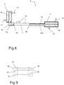
- FIGS 6 and 7 show a side view of a cross section of a heat exchanger 1.
- the heat input section 2 comprises a base plate 11 comprising more than one electronic components 13.
- a second surface 14 of baseplate 11 contacts the walls of the plurality of channels 4 in order to transfer heat generated by the electronic components 13 to the working fluid 5 in the plurality of channels 4.
- the heat exchanger 1 may comprise a bended shape.
- the first heat output section 3a and the second heat output section 3b are bend away from the length direction L of the heat input section 2.
- the heat exchanger 1 may comprise a U-shape where the sides comprise the first heat output section 3a and the second heat output section 3b and the bottom comprises the heat input section 2.
- the same cooling liquid chamber 6 surrounds the plurality of channels 4 in the first heat output section 3a and the second heat output section 3b.
- the first heat output section 3a and the second heat output section 3b have a common cooling liquid chamber 6 and the first heat output section 3a and the second heat output section 3b are cooled with a common cooling liquid 10.
- the cooling liquid 10 is shown with thin arrows in Figures 6-7 .
- cooling liquid inlet 7 in the cooling liquid chamber 6 is arranged between the first heat output section 3a and the second heat output section 3b.
- first heat output section 3a In the vicinity of the first heat output section 3a is arranged at least one cooling liquid outlet 8 in the cooling liquid chamber 6, and in the vicinity of the second heat output section 3b is arranged at least one cooling liquid outlet 8.
- the heat input section 2 may also be in a heat transfer contact with the cooling liquid 10.
- the plurality of channels 4 in the heat input section 2 can be arranged to receive heat through one surface of the plurality of channels 4, and the plurality of channels 4 in the heat input section 2 can be arranged to reject heat through another surface of the plurality of channels 4.
- the plurality of channels 4 in the heat input section 2 receive heat generated by the electronic components 13 through one surface of the plurality of channels 4.
- the one surface faces towards the heat source.
- the received heat is transferred to the working fluid 5 in the plurality of channels 4.
- the plurality of channels 4 in the heat input section 2 reject heat through another surface of the plurality of channels 4.
- the rejected heat is transferred from the working fluid 5 in the plurality of channels 4 to the cooling liquid 10.
- the another surface of the plurality of channels 4 faces towards the heat sink.
- the heat input section 2 is in contact with the cooling liquid 10.
- the same construction may be used by adding an insulation between the heat input section 2 and the cooling liquid 10. The insulation prevents excessive cooling of the plurality of channels 4 in the heat input section 2, e.g. in the baseplate 11 region.
- FIG 8 shows a side view of a cross section of a heat exchanger.
- the heat exchanger 1 comprises thermally insulated sections 17a-b which are thermally insulated from surroundings.
- the thermally insulated section or sections 17a-b are preferably arranged between the heat input section 2 and the heat output section or sections 3a-b.
- the thermally insulated section 17a-b allows spacing heat input section 2 and heat output section 3a-b at a distance apart from one another.
- Figure 8 presents a first thermally insulated section 17a between the first heat output section 3a and the first end 9a of the heat input section 2.
- a second thermally insulated section 17b is positioned between the second heat output section 3b and the second end 9b of the heat input section 2.
- the thermally insulated sections 17a-b are provided with an insulation 18 around the heat exchanger 1 to minimize the heat transfer between the thermally insulated sections 17a-b and the surroundings.
- the heat exchanger 1 may comprise a bended shape.
- the first heat output section 3a is bend away from the length direction L of the heat input section 2.
- the first heat output section 3a is bend towards the side of the heat exchanger 1 which comprises the heat generating components, i.e. electronic components 13.
- the heat exchanger 1 may comprise a L-shape where one side comprises the first heat output section 3a and the other side comprises the second heat output section 3b and the heat input section 2.
- the cooling liquid chambers 6 in a heat exchanger 1 comprising a bended shape can have different dimensions and different positioning of cooling liquid inlets 7 and cooling liquid outlets 8 due to the non-symmetrical shape of the heat exchanger 1.
- a heat exchanger 1 having a symmetrical shape it is often economical to manufacture similar liquid cooling chambers 6 to the heat output sections 3a-b.
- the heat exchanger 1 may be adapted to operate with a closed working fluid 5 loop.
- a closed working fluid 5 loop the ends 19 of the plurality of channels 4 are joined to each other to form a continuous loop where the working fluid 5 can circulate.
- the heat exchanger 1 may be adapted to operate with an open working fluid 5 loop as shown in Figure 9 .
- an open working fluid 5 loop the ends 19 of the plurality of channels 4 are sealed to form a flow path where the working fluid 5 can move between the ends of the plurality of channels 4.
- the plurality of channels 4 are preferably arranged to form a serpentine shaped flow path for the working fluid 5 having a number of turns 20, e.g. U-turns as shown in Figure 9 .
- the number of turns 20 are preferably positioned in the two heat output sections 3a-b.
- the two heat output sections 3a-b are shown with a dotted line in Figure 9 .
- the plurality of channels 4 may also be arranged to form a substantially direct flow path from the first heat output section 3a through the heat input section 2 to the second heat output section 3b, where the flow path has no bends or bends are less than or equal to 90°.
- the heat exchanger 1 adapted to operate as a pulsating heat pipe provided with a liquid cooled heat output sections 3a-b is suitable for a harsh environment.
- possible applications are cooling of drive modules for heavy hybrid or full electric vehicles and marine applications.
- the cooling liquid 10 may comprise engine oil. Engine oil is often already present as a motor cooling liquid and as a lubricant in vehicles, so no extra coolant tanks, pumps nor radiators are required.
- the heat exchanger 1 has a compact size as the two phase working fluid 5 and liquid cooling allow an effective heat transfer.
- the heat exchanger 1 is suitable for cooling power electronic components 13 having a high heat dissipation rate.
- the heat exchanger 1 provided with a liquid cooled heat output sections 3a-b is capable of operating on higher cooling liquid 10 temperatures 50..100°C.
- the heat exchanger 1 adapted to operate as a pulsating heat pipe tolerates peak loading better than conventional heat pipes.
- the pulsating heat pipe heat exchanger 1 allows high vapour slug formation percentage.
Landscapes
- Engineering & Computer Science (AREA)
- Microelectronics & Electronic Packaging (AREA)
- Physics & Mathematics (AREA)
- Thermal Sciences (AREA)
- Life Sciences & Earth Sciences (AREA)
- Sustainable Development (AREA)
- Mechanical Engineering (AREA)
- General Engineering & Computer Science (AREA)
- Cooling Or The Like Of Electrical Apparatus (AREA)
Abstract
Description
- The invention relates to a heat exchanger, and particularly to a heat exchanger comprising a plurality channels which are capillary dimensioned for a working fluid.
- Power electronic components packed in a small volume generate a significant amount of heat and require a reliable and safe cooling system for dissipating the heat.
- The compact size of power electric components demands also a compact size cooling system to fully utilize the obtained space savings in the components.
- The thermal environment where the power electronic component is to operate sets limits to the cooling system. Even if the thermal environment is relatively stable the temperature of the available cooling media may be high.
- An object of the present invention is to solve the above mentioned drawbacks. The objects of the invention are achieved by a heat exchanger which is characterized by what is stated in the independent claim. The preferred embodiments of the invention are disclosed in the dependent claims.
- A heat exchanger comprising a heat input section and a heat output section, and the heat input section and the heat output section containing a working fluid in a plurality of channels. The plurality of channels providing a flow path for the working fluid to move between the heat input section and the heat output section. The plurality of channels being capillary dimensioned for the working fluid. The heat output section comprises a cooling liquid chamber and an inlet and an outlet for cooling liquid. The heat exchanger comprises two heat output sections arranged on the first end and the second end of the heat input section. The plurality of channels extend from the first heat output section through the heat input section to the second heat output section.
- The invented heat exchanger provides a safe and reliable cooling system in a compact size which operates also on higher cooling liquid temperatures.
- In the following the invention will be described in greater detail by means of preferred embodiments with reference to the attached drawings, in which
-
Figure 1 shows a perspective view of a heat exchanger; -
Figure 2 shows a side view of a cross section of a heat exchanger; -
Figure 3 shows heat flows in a heat exchanger oriented horizontally; -
Figure 4 shows heat flows in a heat exchanger oriented vertically; -
Figure 5 shows heat flows in a heat exchanger inclined vertically; -
Figure 6 shows a side view of a cross section of a heat exchanger; -
Figure 7 shows a side view of a cross section of a heat exchanger; -
Figure 8 shows a side view of a cross section of a heat exchanger; -
Figure 9 shows a flow path for a working fluid. -
Figure 1 is a perspective view of aheat exchanger 1. Theheat exchanger 1 comprises aheat input section 2 and twoheat output sections 3a-b. Theheat input section 2 and theheat output sections 3a-b comprise a plurality ofchannels 4. The plurality ofchannels 4 contain a workingfluid 5 and provide a flow path for the workingfluid 5 to move between theheat input section 2 and theheat output sections 3a-b. The plurality ofchannels 4 are capillary dimensioned for the workingfluid 5. The first 3a and second 3b heat output sections comprise acooling liquid chamber 6. Theliquid cooling chamber 6 comprises aninlet 7 and anoutlet 8 for cooling liquid. The firstheat output section 3a and the secondheat output section 3b are arranged on thefirst end 9a and thesecond end 9b of theheat input section 2. The plurality ofchannels 4 extend from the firstheat output section 3a through theheat input section 2 to the secondheat output section 3b. - The plurality of
channels 4 have capillary dimensions. The plurality ofchannels 4 are capillary-sized, in which case they have a size small enough so that bubbles can grow uniquely in a longitudinal direction, i.e. in the longitudinal direction of the channel as opposed to the radial direction, and thereby create a pulsating effect by pushing the workingliquid 5. - The diameter of a channel which is considered capillary depends on the working
fluid 5 that is used and is boiling inside the channel. Examples of working fluids suitable for use in the heat exchanger are R134a (Tetrafluoroethane), R145fa and R1234ze (Tetrafluoropropene) and the respective diameter of the channel varies between 1 to 3 mm. - The plurality of
channels 4 may be produced by dividing pipes into channels by internal walls of the pipes. Thus, each pipe contains several channels. The pipes or tubes may be Multi Port Extruded pipes, for instance. - The
inlet 7 and theoutlet 8 for cooling liquid may be arranged at opposite walls of thecooling liquid chamber 6 as shown inFigures 1-2 . The plurality ofchannels 4 in theheat output section 3a-b can be arranged between theinlet 7 andoutlet 8 so that the flow direction of the workingfluid 5 in the plurality ofchannels 4 is transverse to the flow direction of thecooling liquid 10 flow. Thecooling liquid 10 is shown with thin arrows inFigures 1-2 . Thus theheat output section 3a-b operates then as a cross flow heat exchanger. - A pump may be used for moving the
cooling liquid 10. Thecooling liquid 10 can circulate in a closed loop where it transfers the heat received in theheat output section 3a-b to another media. - The
heat input section 2 may comprise abase plate 11 as shown inFigures 1-2 and6-8 . Thebase plate 11 comprises afirst surface 12 for receivingelectronic components 13. Asecond surface 14 contacts walls of the plurality ofchannels 4 in order to transfer heat generated by theelectronic components 13 to the workingfluid 5 in the plurality ofchannels 4. The heat is conducted from thebase plate 11 to the plurality ofchannels 4 containing the workingfluid 5. - Further, the
second surface 14 may comprise grooves into which the plurality ofchannels 4 can be arranged. Thebase plate 11 can basically consists of a block of a material with a good heat conductivity. Suitable materials include metals, such as aluminium, for instance. The same material or another material with good heat conductivity may be used for the plurality ofchannels 4. - The heat to the
heat input section 2 is provided byelectronic components 13.Electronic components 13 are often designed to dissipate the excess heat mainly via the electronic component's base plate. The electronic component's base plate is arranged in a good thermal connection with theheat input section 13 of theheat exchanger 1. An example of anelectronic component 13 is an IGBT module of a power converter. -
Figure 2 shows a side view of a cross section of aheat exchanger 1. The plurality ofchannels 4 in theheat output sections 3a-b may comprisefins 15 extending from the outer surface of the plurality ofchannels 4. The coolingliquid 10 flows between thefins 15. Thefins 15 increase the heat transfer surface of theheat output section 3a-b but thefins 15 unavoidably increase the pressure drop and consequently increase the coolingliquid 10 pump power requirements to overcome the flow resistance in theheat output section 3a-b. However, as theheat output section 3a-b is liquid cooled the created back pressure is relatively low. - The cooling
liquid chamber 6 preferably surrounds the plurality ofchannels 4 in theheat output section 3a-b providing a leak tight envelope. As a reliable construction is required a friction stir welding can be used to join the coolingliquid chamber 6 and theheat output section 3a-b. - The cooling
liquid chamber 6 may comprise such a volume that the plurality ofchannels 4 in theheat output section 3a-b are immersed in a coolingliquid 10. - In the
heat exchanger 1 adapted to operate as a Pulsating Heat Pipe the workingfluid 5 is transported by means of differential pressure across liquid slugs and vapour slugs from theheat input section 2 to theheat output sections 3a-b and back from theheat output sections 3a-b to theheat input section 2. The Pulsating Heat Pipe involving a plurality ofchannels 4 having capillary dimensions, oscillations occur in a small channel loop heat pipe due to the bidirectional expansion of vapour inside the channels. During operation, the liquid slugs and elongated vapour bubbles will oscillate between a cold region, i.e. theheat output section 3a-b, and a hot region, i.e. theheat input section 2, because of hydrodynamic instabilities caused by the rapid expansion of the bubbles confined in the small channels, and thus provide a fluid velocity almost independent of gravity. Consequently, theheat exchanger 1 works in any orientation, without significant additional costs, and with a workingfluid 5 volume that is smaller than in a conventional cooler, for instance in a liquid cold plate. - The heat flow directions in a
heat exchanger 1 disposed vertically, horizontally and inclined vertically are shown inFigures 3-5 . The advantage of theheat exchanger 1 is that it can be installed in any direction. - The large arrows in the
Figures 3-5 present the coolingliquid 10 flow. The bubbles in the figures present the flow direction of the liquid slugs and the vapour slugs. The small arrows present theheat flow 16 from theelectronic component 13 attached to theheat input section 2. As theheat output sections 3a-b are arranged on the both ends 9a-b of theheat input section 2 theheat exchanger 1 may be oriented freely. - The performance of the
heat exchanger 1 changes depending on the orientation of theheat exchanger 1. Infigure 3 theheat exchanger 1 is oriented horizontally. The liquid slugs and the vapour slugs oscillate between theheat input section 2 and bothheat output section 3a-b substantially similarly. - In
figure 4 the heat exchanger is oriented vertically. The liquid slugs and the vapour slugs oscillate mainly between theheat input section 2 and the firstheat output section 3a which is positioned vertically higher. - In
figure 5 the heat exchanger is inclined vertically. The liquid slugs and the vapour slugs oscillate more between theheat input section 2 and the firstheat output section 3a which is positioned vertically higher than between theheat input section 2 and the secondheat output section 3b which is positioned vertically lower. -
Figures 6 and 7 show a side view of a cross section of aheat exchanger 1. Theheat input section 2 comprises abase plate 11 comprising more than oneelectronic components 13. Asecond surface 14 ofbaseplate 11 contacts the walls of the plurality ofchannels 4 in order to transfer heat generated by theelectronic components 13 to the workingfluid 5 in the plurality ofchannels 4. - As shown in
Figures 6 and 7 theheat exchanger 1 may comprise a bended shape. The firstheat output section 3a and the secondheat output section 3b are bend away from the length direction L of theheat input section 2. - Further, the
heat exchanger 1 may comprise a U-shape where the sides comprise the firstheat output section 3a and the secondheat output section 3b and the bottom comprises theheat input section 2. - The same cooling
liquid chamber 6 surrounds the plurality ofchannels 4 in the firstheat output section 3a and the secondheat output section 3b. The firstheat output section 3a and the secondheat output section 3b have a common coolingliquid chamber 6 and the firstheat output section 3a and the secondheat output section 3b are cooled with acommon cooling liquid 10. The coolingliquid 10 is shown with thin arrows inFigures 6-7 . - In
Figure 6 the coolingliquid inlet 7 in the coolingliquid chamber 6 is arranged between the firstheat output section 3a and the secondheat output section 3b. In the vicinity of the firstheat output section 3a is arranged at least one coolingliquid outlet 8 in the coolingliquid chamber 6, and in the vicinity of the secondheat output section 3b is arranged at least one coolingliquid outlet 8. - In
Figure 7 in the vicinity of the firstheat output section 3a is arranged at least one coolingliquid inlet 7 and in the vicinity of the secondheat output section 3b is arranged at least one coolingliquid outlet 8. - The
heat input section 2 may also be in a heat transfer contact with the coolingliquid 10. The plurality ofchannels 4 in theheat input section 2 can be arranged to receive heat through one surface of the plurality ofchannels 4, and the plurality ofchannels 4 in theheat input section 2 can be arranged to reject heat through another surface of the plurality ofchannels 4. - In
Figures 6-7 the plurality ofchannels 4 in theheat input section 2 receive heat generated by theelectronic components 13 through one surface of the plurality ofchannels 4. The one surface faces towards the heat source. The received heat is transferred to the workingfluid 5 in the plurality ofchannels 4. The plurality ofchannels 4 in theheat input section 2 reject heat through another surface of the plurality ofchannels 4. The rejected heat is transferred from the workingfluid 5 in the plurality ofchannels 4 to the coolingliquid 10. The another surface of the plurality ofchannels 4 faces towards the heat sink. - In the
heat exchanger 1 construction shown inFigures 6-7 theheat input section 2 is in contact with the coolingliquid 10. The same construction may be used by adding an insulation between theheat input section 2 and the coolingliquid 10. The insulation prevents excessive cooling of the plurality ofchannels 4 in theheat input section 2, e.g. in thebaseplate 11 region. -
Figure 8 shows a side view of a cross section of a heat exchanger. Theheat exchanger 1 comprises thermally insulatedsections 17a-b which are thermally insulated from surroundings. The thermally insulated section orsections 17a-b are preferably arranged between theheat input section 2 and the heat output section orsections 3a-b. The thermally insulatedsection 17a-b allows spacingheat input section 2 andheat output section 3a-b at a distance apart from one another. -
Figure 8 presents a first thermally insulatedsection 17a between the firstheat output section 3a and thefirst end 9a of theheat input section 2. A second thermally insulatedsection 17b is positioned between the secondheat output section 3b and thesecond end 9b of theheat input section 2. The thermally insulatedsections 17a-b are provided with aninsulation 18 around theheat exchanger 1 to minimize the heat transfer between the thermally insulatedsections 17a-b and the surroundings. - As shown in
Figure 8 theheat exchanger 1 may comprise a bended shape. The firstheat output section 3a is bend away from the length direction L of theheat input section 2. The firstheat output section 3a is bend towards the side of theheat exchanger 1 which comprises the heat generating components, i.e.electronic components 13. - Further, the
heat exchanger 1 may comprise a L-shape where one side comprises the firstheat output section 3a and the other side comprises the secondheat output section 3b and theheat input section 2. - The cooling
liquid chambers 6 in aheat exchanger 1 comprising a bended shape can have different dimensions and different positioning of coolingliquid inlets 7 and coolingliquid outlets 8 due to the non-symmetrical shape of theheat exchanger 1. In aheat exchanger 1 having a symmetrical shape it is often economical to manufacture similarliquid cooling chambers 6 to theheat output sections 3a-b. - The
heat exchanger 1 may be adapted to operate with a closed workingfluid 5 loop. In a closed workingfluid 5 loop the ends 19 of the plurality ofchannels 4 are joined to each other to form a continuous loop where the workingfluid 5 can circulate. - The
heat exchanger 1 may be adapted to operate with an open workingfluid 5 loop as shown inFigure 9 . In an open workingfluid 5 loop the ends 19 of the plurality ofchannels 4 are sealed to form a flow path where the workingfluid 5 can move between the ends of the plurality ofchannels 4. - The plurality of
channels 4 are preferably arranged to form a serpentine shaped flow path for the workingfluid 5 having a number ofturns 20, e.g. U-turns as shown inFigure 9 . The number ofturns 20 are preferably positioned in the twoheat output sections 3a-b. The twoheat output sections 3a-b are shown with a dotted line inFigure 9 . - The plurality of
channels 4 may also be arranged to form a substantially direct flow path from the firstheat output section 3a through theheat input section 2 to the secondheat output section 3b, where the flow path has no bends or bends are less than or equal to 90°. - The
heat exchanger 1 adapted to operate as a pulsating heat pipe provided with a liquid cooledheat output sections 3a-b is suitable for a harsh environment. For example, possible applications are cooling of drive modules for heavy hybrid or full electric vehicles and marine applications. If theheat exchanger 1 is used in a vehicle the coolingliquid 10 may comprise engine oil. Engine oil is often already present as a motor cooling liquid and as a lubricant in vehicles, so no extra coolant tanks, pumps nor radiators are required. - The
heat exchanger 1 has a compact size as the twophase working fluid 5 and liquid cooling allow an effective heat transfer. Thus theheat exchanger 1 is suitable for cooling powerelectronic components 13 having a high heat dissipation rate. - The
heat exchanger 1 provided with a liquid cooledheat output sections 3a-b is capable of operating onhigher cooling liquid 10 temperatures 50..100°C. - The
heat exchanger 1 adapted to operate as a pulsating heat pipe tolerates peak loading better than conventional heat pipes. The pulsating heatpipe heat exchanger 1 allows high vapour slug formation percentage. - It will be obvious to a person skilled in the art that, as the technology advances, the inventive concept can be implemented in various ways. The invention and its embodiments are not limited to the examples described above but may vary within the scope of the claims.
- Part list: 1 a heat exchanger; 2 a heat input section; 3a-b a first and a second heat output section; 4 a plurality of channels; 5 a working fluid; 6 a cooling liquid chamber; 7 a cooling liquid inlet; 8 a cooling liquid outlet; 9a-b a first end and a second end; 10 a cooling liquid; 11 a base plate; 12 a first surface; 13 an electronic component; 14 a second surface; 15 a fin; 16 a heat flow; 17a-b a first and a second thermally insulated section; 18 an insulation; 19 an end of the plurality of channels; 20 a turn.
- L length direction.
Claims (16)
- A heat exchanger (1) comprising a heat input section (2) and a heat output section (3a-b), the heat input section (2) and the heat output section (3a-b) containing a working fluid (5) in a plurality of channels (4), the plurality of channels (4) providing a flow path for the working fluid (5) to move between the heat input section (2) and the heat output section (3a-b), the plurality of channels (4) being capillary dimensioned for the working fluid (5), characterized in that the heat output section (3a-b) comprises a cooling liquid chamber (6) and an inlet (7) and an outlet (8) for cooling liquid (10), and the heat exchanger (1) comprises two heat output sections (3a-b) arranged on the first end (9a) and the second end (9b) of the heat input section (2) and the plurality of channels (4) extend from the first heat output section (3a) through the heat input section (2) to the second heat output section (3b).
- A heat exchanger according to claim 1, characterized in that the heat input section (2) comprises a base plate (11) comprising a first surface (12) for receiving electronic components (13) and a second surface (14) for contacting walls of the plurality of channels (4) in order to transfer heat generated by the electronic components (13) to the working fluid (5) in the plurality of channels (4).
- A heat exchanger according to any of claims 1 -2, characterized in that the plurality of channels (4) in the heat output sections (3a-b) comprise fins (15) extending from the outer surface of the plurality of channels (4).
- A heat exchanger according to any of claims 1 -3, characterized in that the cooling liquid chamber (6) surrounds the plurality of channels (4) in the heat output section (3a-b).
- A heat exchanger according to claim 4, characterized in that the plurality of channels (4) in the heat output section (3a-b) are immersed in a cooling liquid (10).
- A heat exchanger according to any of claims 1 -5, characterized in that the inlet (7) and the outlet (8) for cooling liquid (10) are arranged at opposite walls of the cooling liquid chamber (6), wherein the plurality of channels (4) in the heat output section (3a-b) are arranged between the inlet (7) and outlet (8) to make the heat output section (3a-b) operate as a cross flow heat exchanger.
- A heat exchanger according to any of claims 1 -6, characterized in that the heat exchanger (1) is adapted to operate as a pulsating heat pipe.
- A heat exchanger according to any of claims 1 -7, characterized in that the heat exchanger (1) is adapted to operate with a closed working fluid (5) loop.
- A heat exchanger according to any of claims 1 -7, characterized in that the heat exchanger (1) is adapted to operate with an open working fluid (5) loop.
- A heat exchanger according to any of claims 1 -9, characterized in that the plurality of channels (4) are arranged to form a serpentine shaped flow path for the working fluid (5) having a number of turns (20), and the number of turns (20) are positioned in the two heat output sections (3a-b).
- A heat exchanger according to any of claims 1 -10, characterized in that the same cooling liquid chamber (6) surrounds the plurality of channels (4) in the first heat output section (3a) and the second heat output section (3b).
- A heat exchanger according to any of claims 1 -11, characterized in that the heat exchanger (1) comprises a bended shape, wherein at least one of the first heat output section (3a) and the second heat output section (3b) is bend away from the length direction (L) of the heat input section (2).
- A heat exchanger according to any of claims 1 -12, characterized in the plurality of channels (4) in the heat input section (2) are arranged to receive heat through one surface of the plurality of channels (4), and the plurality of channels (4) in the heat input section (2) are arranged to reject heat through another surface of the plurality of channels (4).
- A heat exchanger according to any of claims 1 -13, characterized in the that heat exchanger (1) comprises a first thermally insulated section (17a) between the first heat output section (3a) and the first end (9a) of the heat input section (2) and/or a second thermally insulated section (17b) between the second heat output section (3b) and the second end (9b) of the heat input section (2).
- A heat exchanger according to any of claims 1 -14, characterized in that the electronic component (13) is an IGBT module of a power converter.
- Use of the heat exchanger according to any of claims 1-15 in a vehicle, characterized in that the cooling liquid (10) comprises engine oil.
Priority Applications (1)
| Application Number | Priority Date | Filing Date | Title |
|---|---|---|---|
| EP17155992.5A EP3361847B1 (en) | 2017-02-14 | 2017-02-14 | A heat exchanger |
Applications Claiming Priority (1)
| Application Number | Priority Date | Filing Date | Title |
|---|---|---|---|
| EP17155992.5A EP3361847B1 (en) | 2017-02-14 | 2017-02-14 | A heat exchanger |
Publications (2)
| Publication Number | Publication Date |
|---|---|
| EP3361847A1 true EP3361847A1 (en) | 2018-08-15 |
| EP3361847B1 EP3361847B1 (en) | 2021-03-31 |
Family
ID=58043950
Family Applications (1)
| Application Number | Title | Priority Date | Filing Date |
|---|---|---|---|
| EP17155992.5A Active EP3361847B1 (en) | 2017-02-14 | 2017-02-14 | A heat exchanger |
Country Status (1)
| Country | Link |
|---|---|
| EP (1) | EP3361847B1 (en) |
Cited By (1)
| Publication number | Priority date | Publication date | Assignee | Title |
|---|---|---|---|---|
| EP3816562B1 (en) * | 2019-10-31 | 2023-05-03 | Hamilton Sundstrand Corporation | Oscillating heat pipe integrated thermal management system for power electronics |
Citations (5)
| Publication number | Priority date | Publication date | Assignee | Title |
|---|---|---|---|---|
| EP0390053A1 (en) * | 1989-03-29 | 1990-10-03 | Hughes Aircraft Company | Heat conducting interface for electric module |
| US20060146496A1 (en) * | 2005-01-06 | 2006-07-06 | The Boeing Company | Cooling apparatus, system, and associated method |
| US20150060019A1 (en) * | 2013-09-02 | 2015-03-05 | Industrial Technology Research Institute | Pulsating multi-pipe heat pipe |
| CN104792200A (en) * | 2015-04-17 | 2015-07-22 | 浙江大学 | Pulsating heat pipe heat exchanger with lyophilic coatings |
| EP2988578A1 (en) * | 2014-08-19 | 2016-02-24 | ABB Technology Oy | Cooling element |
-
2017
- 2017-02-14 EP EP17155992.5A patent/EP3361847B1/en active Active
Patent Citations (5)
| Publication number | Priority date | Publication date | Assignee | Title |
|---|---|---|---|---|
| EP0390053A1 (en) * | 1989-03-29 | 1990-10-03 | Hughes Aircraft Company | Heat conducting interface for electric module |
| US20060146496A1 (en) * | 2005-01-06 | 2006-07-06 | The Boeing Company | Cooling apparatus, system, and associated method |
| US20150060019A1 (en) * | 2013-09-02 | 2015-03-05 | Industrial Technology Research Institute | Pulsating multi-pipe heat pipe |
| EP2988578A1 (en) * | 2014-08-19 | 2016-02-24 | ABB Technology Oy | Cooling element |
| CN104792200A (en) * | 2015-04-17 | 2015-07-22 | 浙江大学 | Pulsating heat pipe heat exchanger with lyophilic coatings |
Cited By (1)
| Publication number | Priority date | Publication date | Assignee | Title |
|---|---|---|---|---|
| EP3816562B1 (en) * | 2019-10-31 | 2023-05-03 | Hamilton Sundstrand Corporation | Oscillating heat pipe integrated thermal management system for power electronics |
Also Published As
| Publication number | Publication date |
|---|---|
| EP3361847B1 (en) | 2021-03-31 |
Similar Documents
| Publication | Publication Date | Title |
|---|---|---|
| US7686069B2 (en) | Cooling apparatus having low profile extrusion and method of manufacture therefor | |
| US7788933B2 (en) | Heat exchanger tube having integrated thermoelectric devices | |
| US4976308A (en) | Thermal energy storage heat exchanger | |
| CN102083297B (en) | heat exchanger | |
| US7506682B2 (en) | Liquid cooled thermosiphon for electronic components | |
| Jung et al. | Microchannel cooling strategies for high heat flux (1 kW/cm 2) power electronic applications | |
| US20160123637A1 (en) | Two-phase heat exchanger for cooling electrical components | |
| KR19990067040A (en) | Fluid Cooling Radiator for Electronic Device Cooling | |
| JP7018147B2 (en) | Phase change cooling module and battery pack using it | |
| CN102297612A (en) | Heat exchanger | |
| CN106304805A (en) | A kind of plate-fin microcirculation radiator and microcirculation heat-exchange system | |
| CN106839840B (en) | A heat transfer method and heat transfer system based on thermal pressure conversion effect | |
| Khairnasov et al. | Heat pipes application in electronics thermal control systems | |
| US11566849B2 (en) | Reservoir and liquid-cooling radiator | |
| Tripathi et al. | Performance investigation of automobile radiator operated with ZnFe2O4 nano fluid based coolant | |
| US6354002B1 (en) | Method of making a thick, low cost liquid heat transfer plate with vertically aligned fluid channels | |
| JP7133044B2 (en) | Self-oscillating heat pipe cooler | |
| WO2020152822A1 (en) | Cooling device | |
| US7992625B1 (en) | Fluid-operated heat transfer device | |
| EP3361847B1 (en) | A heat exchanger | |
| JP2009277699A (en) | Heat sink, heat sink assembly, semiconductor module, and semiconductor device with cooling device | |
| CN112992817A (en) | Micro-channel self-driven internal circulation convection enhanced heat transfer method | |
| CN112584671A (en) | Vapor chamber for cooling electronic components | |
| CN115773681A (en) | Heat dissipation device based on loop heat pipe | |
| CN219577625U (en) | Heat radiation module for heat exchange between two-phase flow circulation steam cavity and cold liquid fluid |
Legal Events
| Date | Code | Title | Description |
|---|---|---|---|
| PUAI | Public reference made under article 153(3) epc to a published international application that has entered the european phase |
Free format text: ORIGINAL CODE: 0009012 |
|
| STAA | Information on the status of an ep patent application or granted ep patent |
Free format text: STATUS: REQUEST FOR EXAMINATION WAS MADE |
|
| 17P | Request for examination filed |
Effective date: 20180614 |
|
| AK | Designated contracting states |
Kind code of ref document: A1 Designated state(s): AL AT BE BG CH CY CZ DE DK EE ES FI FR GB GR HR HU IE IS IT LI LT LU LV MC MK MT NL NO PL PT RO RS SE SI SK SM TR |
|
| AX | Request for extension of the european patent |
Extension state: BA ME |
|
| RAP1 | Party data changed (applicant data changed or rights of an application transferred) |
Owner name: ABB SCHWEIZ AG |
|
| STAA | Information on the status of an ep patent application or granted ep patent |
Free format text: STATUS: EXAMINATION IS IN PROGRESS |
|
| 17Q | First examination report despatched |
Effective date: 20190521 |
|
| GRAP | Despatch of communication of intention to grant a patent |
Free format text: ORIGINAL CODE: EPIDOSNIGR1 |
|
| STAA | Information on the status of an ep patent application or granted ep patent |
Free format text: STATUS: GRANT OF PATENT IS INTENDED |
|
| INTG | Intention to grant announced |
Effective date: 20201002 |
|
| RAP1 | Party data changed (applicant data changed or rights of an application transferred) |
Owner name: ABB SCHWEIZ AG |
|
| GRAS | Grant fee paid |
Free format text: ORIGINAL CODE: EPIDOSNIGR3 |
|
| GRAA | (expected) grant |
Free format text: ORIGINAL CODE: 0009210 |
|
| STAA | Information on the status of an ep patent application or granted ep patent |
Free format text: STATUS: THE PATENT HAS BEEN GRANTED |
|
| AK | Designated contracting states |
Kind code of ref document: B1 Designated state(s): AL AT BE BG CH CY CZ DE DK EE ES FI FR GB GR HR HU IE IS IT LI LT LU LV MC MK MT NL NO PL PT RO RS SE SI SK SM TR |
|
| REG | Reference to a national code |
Ref country code: GB Ref legal event code: FG4D Ref country code: CH Ref legal event code: EP |
|
| REG | Reference to a national code |
Ref country code: AT Ref legal event code: REF Ref document number: 1378461 Country of ref document: AT Kind code of ref document: T Effective date: 20210415 |
|
| REG | Reference to a national code |
Ref country code: DE Ref legal event code: R096 Ref document number: 602017035522 Country of ref document: DE |
|
| REG | Reference to a national code |
Ref country code: IE Ref legal event code: FG4D |
|
| REG | Reference to a national code |
Ref country code: LT Ref legal event code: MG9D |
|
| PG25 | Lapsed in a contracting state [announced via postgrant information from national office to epo] |
Ref country code: BG Free format text: LAPSE BECAUSE OF FAILURE TO SUBMIT A TRANSLATION OF THE DESCRIPTION OR TO PAY THE FEE WITHIN THE PRESCRIBED TIME-LIMIT Effective date: 20210630 Ref country code: FI Free format text: LAPSE BECAUSE OF FAILURE TO SUBMIT A TRANSLATION OF THE DESCRIPTION OR TO PAY THE FEE WITHIN THE PRESCRIBED TIME-LIMIT Effective date: 20210331 Ref country code: HR Free format text: LAPSE BECAUSE OF FAILURE TO SUBMIT A TRANSLATION OF THE DESCRIPTION OR TO PAY THE FEE WITHIN THE PRESCRIBED TIME-LIMIT Effective date: 20210331 Ref country code: NO Free format text: LAPSE BECAUSE OF FAILURE TO SUBMIT A TRANSLATION OF THE DESCRIPTION OR TO PAY THE FEE WITHIN THE PRESCRIBED TIME-LIMIT Effective date: 20210630 |
|
| PG25 | Lapsed in a contracting state [announced via postgrant information from national office to epo] |
Ref country code: SE Free format text: LAPSE BECAUSE OF FAILURE TO SUBMIT A TRANSLATION OF THE DESCRIPTION OR TO PAY THE FEE WITHIN THE PRESCRIBED TIME-LIMIT Effective date: 20210331 Ref country code: RS Free format text: LAPSE BECAUSE OF FAILURE TO SUBMIT A TRANSLATION OF THE DESCRIPTION OR TO PAY THE FEE WITHIN THE PRESCRIBED TIME-LIMIT Effective date: 20210331 Ref country code: LV Free format text: LAPSE BECAUSE OF FAILURE TO SUBMIT A TRANSLATION OF THE DESCRIPTION OR TO PAY THE FEE WITHIN THE PRESCRIBED TIME-LIMIT Effective date: 20210331 |
|
| REG | Reference to a national code |
Ref country code: NL Ref legal event code: MP Effective date: 20210331 |
|
| REG | Reference to a national code |
Ref country code: AT Ref legal event code: MK05 Ref document number: 1378461 Country of ref document: AT Kind code of ref document: T Effective date: 20210331 |
|
| PG25 | Lapsed in a contracting state [announced via postgrant information from national office to epo] |
Ref country code: AT Free format text: LAPSE BECAUSE OF FAILURE TO SUBMIT A TRANSLATION OF THE DESCRIPTION OR TO PAY THE FEE WITHIN THE PRESCRIBED TIME-LIMIT Effective date: 20210331 Ref country code: NL Free format text: LAPSE BECAUSE OF FAILURE TO SUBMIT A TRANSLATION OF THE DESCRIPTION OR TO PAY THE FEE WITHIN THE PRESCRIBED TIME-LIMIT Effective date: 20210331 Ref country code: SM Free format text: LAPSE BECAUSE OF FAILURE TO SUBMIT A TRANSLATION OF THE DESCRIPTION OR TO PAY THE FEE WITHIN THE PRESCRIBED TIME-LIMIT Effective date: 20210331 Ref country code: LT Free format text: LAPSE BECAUSE OF FAILURE TO SUBMIT A TRANSLATION OF THE DESCRIPTION OR TO PAY THE FEE WITHIN THE PRESCRIBED TIME-LIMIT Effective date: 20210331 Ref country code: EE Free format text: LAPSE BECAUSE OF FAILURE TO SUBMIT A TRANSLATION OF THE DESCRIPTION OR TO PAY THE FEE WITHIN THE PRESCRIBED TIME-LIMIT Effective date: 20210331 Ref country code: CZ Free format text: LAPSE BECAUSE OF FAILURE TO SUBMIT A TRANSLATION OF THE DESCRIPTION OR TO PAY THE FEE WITHIN THE PRESCRIBED TIME-LIMIT Effective date: 20210331 |
|
| PG25 | Lapsed in a contracting state [announced via postgrant information from national office to epo] |
Ref country code: IS Free format text: LAPSE BECAUSE OF FAILURE TO SUBMIT A TRANSLATION OF THE DESCRIPTION OR TO PAY THE FEE WITHIN THE PRESCRIBED TIME-LIMIT Effective date: 20210731 Ref country code: PT Free format text: LAPSE BECAUSE OF FAILURE TO SUBMIT A TRANSLATION OF THE DESCRIPTION OR TO PAY THE FEE WITHIN THE PRESCRIBED TIME-LIMIT Effective date: 20210802 Ref country code: PL Free format text: LAPSE BECAUSE OF FAILURE TO SUBMIT A TRANSLATION OF THE DESCRIPTION OR TO PAY THE FEE WITHIN THE PRESCRIBED TIME-LIMIT Effective date: 20210331 Ref country code: SK Free format text: LAPSE BECAUSE OF FAILURE TO SUBMIT A TRANSLATION OF THE DESCRIPTION OR TO PAY THE FEE WITHIN THE PRESCRIBED TIME-LIMIT Effective date: 20210331 Ref country code: RO Free format text: LAPSE BECAUSE OF FAILURE TO SUBMIT A TRANSLATION OF THE DESCRIPTION OR TO PAY THE FEE WITHIN THE PRESCRIBED TIME-LIMIT Effective date: 20210331 |
|
| REG | Reference to a national code |
Ref country code: DE Ref legal event code: R097 Ref document number: 602017035522 Country of ref document: DE |
|
| PG25 | Lapsed in a contracting state [announced via postgrant information from national office to epo] |
Ref country code: DK Free format text: LAPSE BECAUSE OF FAILURE TO SUBMIT A TRANSLATION OF THE DESCRIPTION OR TO PAY THE FEE WITHIN THE PRESCRIBED TIME-LIMIT Effective date: 20210331 Ref country code: AL Free format text: LAPSE BECAUSE OF FAILURE TO SUBMIT A TRANSLATION OF THE DESCRIPTION OR TO PAY THE FEE WITHIN THE PRESCRIBED TIME-LIMIT Effective date: 20210331 Ref country code: ES Free format text: LAPSE BECAUSE OF FAILURE TO SUBMIT A TRANSLATION OF THE DESCRIPTION OR TO PAY THE FEE WITHIN THE PRESCRIBED TIME-LIMIT Effective date: 20210331 |
|
| PLBE | No opposition filed within time limit |
Free format text: ORIGINAL CODE: 0009261 |
|
| STAA | Information on the status of an ep patent application or granted ep patent |
Free format text: STATUS: NO OPPOSITION FILED WITHIN TIME LIMIT |
|
| 26N | No opposition filed |
Effective date: 20220104 |
|
| PG25 | Lapsed in a contracting state [announced via postgrant information from national office to epo] |
Ref country code: IS Free format text: LAPSE BECAUSE OF FAILURE TO SUBMIT A TRANSLATION OF THE DESCRIPTION OR TO PAY THE FEE WITHIN THE PRESCRIBED TIME-LIMIT Effective date: 20210731 |
|
| PG25 | Lapsed in a contracting state [announced via postgrant information from national office to epo] |
Ref country code: IT Free format text: LAPSE BECAUSE OF FAILURE TO SUBMIT A TRANSLATION OF THE DESCRIPTION OR TO PAY THE FEE WITHIN THE PRESCRIBED TIME-LIMIT Effective date: 20210331 |
|
| PG25 | Lapsed in a contracting state [announced via postgrant information from national office to epo] |
Ref country code: MC Free format text: LAPSE BECAUSE OF FAILURE TO SUBMIT A TRANSLATION OF THE DESCRIPTION OR TO PAY THE FEE WITHIN THE PRESCRIBED TIME-LIMIT Effective date: 20210331 |
|
| REG | Reference to a national code |
Ref country code: CH Ref legal event code: PL |
|
| REG | Reference to a national code |
Ref country code: BE Ref legal event code: MM Effective date: 20220228 |
|
| PG25 | Lapsed in a contracting state [announced via postgrant information from national office to epo] |
Ref country code: LU Free format text: LAPSE BECAUSE OF NON-PAYMENT OF DUE FEES Effective date: 20220214 |
|
| PG25 | Lapsed in a contracting state [announced via postgrant information from national office to epo] |
Ref country code: LI Free format text: LAPSE BECAUSE OF NON-PAYMENT OF DUE FEES Effective date: 20220228 Ref country code: IE Free format text: LAPSE BECAUSE OF NON-PAYMENT OF DUE FEES Effective date: 20220214 Ref country code: CH Free format text: LAPSE BECAUSE OF NON-PAYMENT OF DUE FEES Effective date: 20220228 |
|
| PG25 | Lapsed in a contracting state [announced via postgrant information from national office to epo] |
Ref country code: BE Free format text: LAPSE BECAUSE OF NON-PAYMENT OF DUE FEES Effective date: 20220228 |
|
| PG25 | Lapsed in a contracting state [announced via postgrant information from national office to epo] |
Ref country code: HU Free format text: LAPSE BECAUSE OF FAILURE TO SUBMIT A TRANSLATION OF THE DESCRIPTION OR TO PAY THE FEE WITHIN THE PRESCRIBED TIME-LIMIT; INVALID AB INITIO Effective date: 20170214 |
|
| PG25 | Lapsed in a contracting state [announced via postgrant information from national office to epo] |
Ref country code: MK Free format text: LAPSE BECAUSE OF FAILURE TO SUBMIT A TRANSLATION OF THE DESCRIPTION OR TO PAY THE FEE WITHIN THE PRESCRIBED TIME-LIMIT Effective date: 20210331 Ref country code: CY Free format text: LAPSE BECAUSE OF FAILURE TO SUBMIT A TRANSLATION OF THE DESCRIPTION OR TO PAY THE FEE WITHIN THE PRESCRIBED TIME-LIMIT Effective date: 20210331 |
|
| PG25 | Lapsed in a contracting state [announced via postgrant information from national office to epo] |
Ref country code: MT Free format text: LAPSE BECAUSE OF FAILURE TO SUBMIT A TRANSLATION OF THE DESCRIPTION OR TO PAY THE FEE WITHIN THE PRESCRIBED TIME-LIMIT Effective date: 20210331 |
|
| PG25 | Lapsed in a contracting state [announced via postgrant information from national office to epo] |
Ref country code: GR Free format text: LAPSE BECAUSE OF NON-PAYMENT OF DUE FEES Effective date: 20210331 |
|
| PG25 | Lapsed in a contracting state [announced via postgrant information from national office to epo] |
Ref country code: GR Free format text: LAPSE BECAUSE OF NON-PAYMENT OF DUE FEES Effective date: 20210331 |
|
| PGFP | Annual fee paid to national office [announced via postgrant information from national office to epo] |
Ref country code: DE Payment date: 20250218 Year of fee payment: 9 |
|
| PGFP | Annual fee paid to national office [announced via postgrant information from national office to epo] |
Ref country code: FR Payment date: 20250221 Year of fee payment: 9 |
|
| PGFP | Annual fee paid to national office [announced via postgrant information from national office to epo] |
Ref country code: GB Payment date: 20250220 Year of fee payment: 9 |
|
| PG25 | Lapsed in a contracting state [announced via postgrant information from national office to epo] |
Ref country code: TR Free format text: LAPSE BECAUSE OF FAILURE TO SUBMIT A TRANSLATION OF THE DESCRIPTION OR TO PAY THE FEE WITHIN THE PRESCRIBED TIME-LIMIT Effective date: 20210331 |