EP3361825A1 - Trimmable heat blanket and heating method - Google Patents
Trimmable heat blanket and heating method Download PDFInfo
- Publication number
- EP3361825A1 EP3361825A1 EP17203822.6A EP17203822A EP3361825A1 EP 3361825 A1 EP3361825 A1 EP 3361825A1 EP 17203822 A EP17203822 A EP 17203822A EP 3361825 A1 EP3361825 A1 EP 3361825A1
- Authority
- EP
- European Patent Office
- Prior art keywords
- heating element
- resistive heating
- element circuits
- electrical
- blanket
- Prior art date
- Legal status (The legal status is an assumption and is not a legal conclusion. Google has not performed a legal analysis and makes no representation as to the accuracy of the status listed.)
- Granted
Links
Images



Classifications
-
- H—ELECTRICITY
- H05—ELECTRIC TECHNIQUES NOT OTHERWISE PROVIDED FOR
- H05B—ELECTRIC HEATING; ELECTRIC LIGHT SOURCES NOT OTHERWISE PROVIDED FOR; CIRCUIT ARRANGEMENTS FOR ELECTRIC LIGHT SOURCES, IN GENERAL
- H05B3/00—Ohmic-resistance heating
- H05B3/20—Heating elements having extended surface area substantially in a two-dimensional [2D] plane, e.g. plate-heater
- H05B3/34—Heating elements having extended surface area substantially in a two-dimensional [2D] plane, e.g. plate-heater flexible, e.g. heating nets or webs
- H05B3/342—Heating elements having extended surface area substantially in a two-dimensional [2D] plane, e.g. plate-heater flexible, e.g. heating nets or webs heaters used in textiles
-
- H—ELECTRICITY
- H05—ELECTRIC TECHNIQUES NOT OTHERWISE PROVIDED FOR
- H05B—ELECTRIC HEATING; ELECTRIC LIGHT SOURCES NOT OTHERWISE PROVIDED FOR; CIRCUIT ARRANGEMENTS FOR ELECTRIC LIGHT SOURCES, IN GENERAL
- H05B3/00—Ohmic-resistance heating
- H05B3/20—Heating elements having extended surface area substantially in a two-dimensional [2D] plane, e.g. plate-heater
- H05B3/34—Heating elements having extended surface area substantially in a two-dimensional [2D] plane, e.g. plate-heater flexible, e.g. heating nets or webs
- H05B3/36—Heating elements having extended surface area substantially in a two-dimensional [2D] plane, e.g. plate-heater flexible, e.g. heating nets or webs heating conductor embedded in insulating material
-
- A—HUMAN NECESSITIES
- A47—FURNITURE; DOMESTIC ARTICLES OR APPLIANCES; COFFEE MILLS; SPICE MILLS; SUCTION CLEANERS IN GENERAL
- A47G—HOUSEHOLD OR TABLE EQUIPMENT
- A47G9/00—Bed-covers; Counterpanes; Travelling rugs; Sleeping rugs; Sleeping bags; Pillows
- A47G9/02—Bed linen; Blankets; Counterpanes
- A47G9/0207—Blankets; Duvets
- A47G9/0215—Blankets; Duvets with cooling or heating means
-
- B—PERFORMING OPERATIONS; TRANSPORTING
- B26—HAND CUTTING TOOLS; CUTTING; SEVERING
- B26D—CUTTING; DETAILS COMMON TO MACHINES FOR PERFORATING, PUNCHING, CUTTING-OUT, STAMPING-OUT OR SEVERING
- B26D7/00—Details of apparatus for cutting, cutting-out, stamping-out, punching, perforating, or severing by means other than cutting
-
- H—ELECTRICITY
- H05—ELECTRIC TECHNIQUES NOT OTHERWISE PROVIDED FOR
- H05B—ELECTRIC HEATING; ELECTRIC LIGHT SOURCES NOT OTHERWISE PROVIDED FOR; CIRCUIT ARRANGEMENTS FOR ELECTRIC LIGHT SOURCES, IN GENERAL
- H05B1/00—Details of electric heating devices
- H05B1/02—Automatic switching arrangements specially adapted to apparatus ; Control of heating devices
- H05B1/0227—Applications
- H05B1/023—Industrial applications
- H05B1/0236—Industrial applications for vehicles
-
- H—ELECTRICITY
- H05—ELECTRIC TECHNIQUES NOT OTHERWISE PROVIDED FOR
- H05B—ELECTRIC HEATING; ELECTRIC LIGHT SOURCES NOT OTHERWISE PROVIDED FOR; CIRCUIT ARRANGEMENTS FOR ELECTRIC LIGHT SOURCES, IN GENERAL
- H05B3/00—Ohmic-resistance heating
- H05B3/02—Details
-
- H—ELECTRICITY
- H05—ELECTRIC TECHNIQUES NOT OTHERWISE PROVIDED FOR
- H05B—ELECTRIC HEATING; ELECTRIC LIGHT SOURCES NOT OTHERWISE PROVIDED FOR; CIRCUIT ARRANGEMENTS FOR ELECTRIC LIGHT SOURCES, IN GENERAL
- H05B3/00—Ohmic-resistance heating
- H05B3/20—Heating elements having extended surface area substantially in a two-dimensional [2D] plane, e.g. plate-heater
- H05B3/34—Heating elements having extended surface area substantially in a two-dimensional [2D] plane, e.g. plate-heater flexible, e.g. heating nets or webs
-
- H—ELECTRICITY
- H05—ELECTRIC TECHNIQUES NOT OTHERWISE PROVIDED FOR
- H05B—ELECTRIC HEATING; ELECTRIC LIGHT SOURCES NOT OTHERWISE PROVIDED FOR; CIRCUIT ARRANGEMENTS FOR ELECTRIC LIGHT SOURCES, IN GENERAL
- H05B2203/00—Aspects relating to Ohmic resistive heating covered by group H05B3/00
- H05B2203/002—Heaters using a particular layout for the resistive material or resistive elements
- H05B2203/005—Heaters using a particular layout for the resistive material or resistive elements using multiple resistive elements or resistive zones isolated from each other
Definitions
- the present disclosure generally relates to equipment and methods for heating a structure, and deals more particularly with an electrical heat blanket that can be trimmed to a desired shape and/or size, and a method of using the blanket to heat a structure.
- Electrical heat blankets are used to provide surface heating of structures and parts in a variety of applications. For example, heat blankets are used to cure composite patches placed on a structure requiring repair. These heat blankets, which use electrically powered resistive heating elements, are manufactured in standard sizes and shapes.
- a heat blanket matching the size of the repair area may not be available. Consequently, if an oversized heat blanket is used, it must be folded over or otherwise temporarily modified in order to only apply heat to the desired coverage area.
- an oversized heat blanket also may increase the risk of overheating a repair area, and/or a nearby heat sensitive structure.
- Custom sized heat blankets can be fabricated, but the lead time needed to design and produce them may be too long for applications such as in-service aircraft repairs requiring immediate attention.
- the disclosure relates in general to equipment and methods for local surface heating of a structure, such as a composite repair patch on an aircraft, and more specifically to an electrical heat blanket that can be trimmed to a desired size and/or shape.
- the disclosure also relates to a method of heating a structure using the heat blanket.
- a heating apparatus comprises a blanket and an array of individual resistive heating element circuits inside the blanket.
- the individual resistive heating element circuits are configured to be coupled with a source of electrical power, and are spaced apart from each other to allow the blanket to be cut to a desired shape and/or size.
- a heat apparatus comprises a heat blanket and a resistive heating element circuit embedded therein.
- the resistive heating circuit is configured to be coupled with a source of electrical power and includes a plurality of individual resistive heating element circuits arranged in a configuration that allows the heat blanket to be cut to a desired shape and/or size while maintaining electrical continuity.
- a method of making a heating apparatus.
- the method comprises providing an electrical heat blanket having an array of individual resistive heating element circuits therein that are adapted to be coupled with a source of electrical power.
- the method further also includes trimming the electrical heat blanket to a desired shape, including removing at least certain of the individual resistive heating element circuits.
- One of the advantages of the disclosed heat blanket is that it can be quickly and easily trimmed to a desired shape and/or size. Another advantage of the heat blanket is that it avoids overheating a structure, or damaging nearby heat sensitive components. A further advantage lies in elimination of the need for custom made heat blankets, and the long lead times required to fabricate such blankets.
- heating apparatus 18 in the form of a flexible, electrical heat blanket 20 is coupled by external power and control lines 22 to a controller 24 which includes a source of electrical power (not shown).
- the heat blanket 20 can comprise a resistive heating element circuit 34, which may comprise a printed flex circuit, embedded in and laminated between two layers of flexible material 38.
- Each of the two layers of flexible material 38 may comprise a vulcanized silicone rubber reinforced with a layer (not shown) of fiberglass.
- the flexible material 38 may comprise latex rubber or any of various other elastomers.
- the flexible material 38 may comprise polyimide, Kapton® or other flexible films.
- the resistive heating element circuit 34 may be embedded in a single layer of flexible material 38, as by insert molding.
- the resistive heating element circuit 34 includes a series of later discussed electrical leads (not shown) coupled to one or more bus bars (not shown) that are connected to the external power and control lines 22 via an entry tab 36 on the heat blanket 20.
- the blanket 20 is placed on a structure 28, such as a skin of an aircraft, overlying a composite repair patch 30 that requires thermal curing according to a predefined cure schedule.
- a structure 28 such as a skin of an aircraft
- the heat blanket 20 can be easily specifically tailored to the size and shape of a repair area 31 containing the composite repair patch 30.
- one or more thermocouples 32 may be placed beneath the heat blanket 20, immediately outside the edges of the repair patch 30.
- the thermocouples 32 are coupled by electrical lines 26 to the controller 24.
- the controller 24 receives signals from the thermocouples 32 representing the sensed temperature of the heat blanket 20. Based on this sensed temperature, controller 24 adjusts AC power supplied to the heat blanket 20 in a manner that controls the temperature of the heat blanket 20 according to the cure schedule.
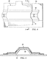
- Figures 4 and 5 illustrate a typical application of the flexible heat blanket 20 that has been trimmed to size.
- the heat blanket 20 has been trimmed to a width that wraps over and extends slightly beyond the edges of a stringer 66 on a skin 64, and a length that is sufficient to cover an underlying repair area 31. Due to its flexibility, the heat blanket 20 conforms to the contour of the stringer 66 and to the skin 64.
- the resistive heating element circuit 34 may comprise an N X M, two-dimensional array 46 of individual resistive heating element circuits 42, arranged in aligned N rows and M columns.
- the individual resistive heating element circuits 42 can be substantially identical in size and shape.
- the resistive heating element circuit 34 may comprise a one-dimensional array 62 (see Figure 12 ) of individual resistive heating element circuits 42. In the example shown in Figure 6 , the circuits are arranged in a 4 x 4 two-dimensional array 46, however the array 46 may contain any number of individual resistive heating element circuits 42.
- the individual resistive heating element circuits 42 may be arranged in an irregular array or in an array that is not rectilinear. Any of various array geometries are possible. Moreover, the individual resistive heating element circuits 42 may be any size suitable for the application, and while they are identical in size in the illustrated example, the array may contain resistive heating elements circuits 42 having differing sizes.
- Each of the individual circuits 42 is independently connected by a pair of electrical lines 48 (see Figure 6A ) to an electrical bus 52 which in turn is connected to the controller 24 by a suitable electrical coupling. Thus, it may be appreciated that the individual circuits 42 are connected to the power source in parallel with each other.
- the bus 52 may be connected to a simple electrical plug 50 that can be inserted into an AC power outlet (not shown).
- the individual circuits 42 are spaced apart from each other at a distance "D". Due to the alignment of the individual circuits 42 in the array 46, the spacing 35 between the individual circuits 42 is substantially constant and occur at regular intervals throughout the array 46.
- the provision of regular spacing 35 throughout the array 46 assists a technician in trimming the heat blanket 20 trimmed to a desired shape and/or size suitable for individual applications, while maintaining electrical continuity of the electrical heating circuit.
- the spacing 35 between the individual circuits 42 may not be regular.
- the heat blanket 20 is trimmed to size by cutting or otherwise severing portions of the heat blanket 20 along cut lines 54 ( Figure 7 ) within the spacing 35 between the individual circuits 42.
- the cut lines 54 may be printed, embossed or otherwise formed on the outside surface of the heat blanket 20, thus providing a visual guide that allows a technician to cut the heat blanket 20 to the desired shape without impairing its functionality. This cutting operation may be performed using a knife, scissors or other suitable cutting devices.
- Figures 9-11 illustrate another example of the trimmable heat blanket 20.
- the individual circuits 42 are connected to each other by electrical interconnect leads 56 which couple individual circuits 42 in a series circuit with the power source.
- a cut line 54 has been chosen that results in eight of the individual circuits 42 being separated 60 ( Figure 11 ) from the heat blanket 20a when trimmed to size.
- cutting away these individual circuits severs several of the electrical interconnect leads 56 between the individual circuits 42 which are to remain active.
- jumper wires 58 are installed where necessary to interconnect the individual circuits 42 that have severed interconnect leads 56.
- FIGs 12 and 13 illustrate another example of the heat blanket 20 in which the individual circuits 42 are arranged as a linear, one-dimensional array 62, suitable for use in applications such as the composite repair example shown in in Figures 4 and 5 .
- the individual circuits 42 can be connected in series with each other, however, in other examples they be connected in parallel with each other, similar to the example shown in in Figure 6 .
- the heat blanket 20 may be trimmed to a desired length "L" by severing it along a cut line 54 within the spacing 35 between adjacent ones of the individual circuits 42. In the series connected circuit 34 shown in Figure 12 , cutting the heat blanket 20 along the cut line 54 breaks electrical continuity within the circuit 34.
- Figures 14-16 illustrate a prefabricated electrical connector module 70 that may be used in lieu of jumper wires 58 to reestablish electrical continuity in a heat blanket 20 that has been trimmed to size/shape.
- the connector modules 70 may be made in standard sizes so as to be geometrically compatible with a standard grid spacing and sub-circuit size for a given heat blanket 20, such that they can be snapped onto the ends of the electrical leads 56 wherever needed to reestablish electrical continuity that has been interrupted as a result of cuts made in the heat blanket 20.
- the connector module 70 may be formed of any suitable nonconductive material such as a molded plastic that does not soften or degrade when subjected to the temperatures produced by the heat blanket 20.
- the connector module 70 has a substantially straight body 80 and is used to connect exposed ends of electrical leads 56 (see Figure 12 ) that have been severed as result of a trimming operation.
- the connector module 70 includes a pair of electrically conductive sockets 72 in one side thereof which are connected together by an internal conductor 76.
- the sockets 72 are spaced apart a distance that substantially matches the distance between exposed conductor ends 68.
- a section 82 of the blanket 20 along an edge 84 of the heat blanket 20 is stripped away using any suitable technique, exposing the conductor ends 68.
- the conductor ends 68 are electrically reconnected by plugging them into the sockets 72 of the connector module 70. Effectively, the connector module 70 is "snapped" onto the exposed conductor ends 68.
- Figure 17 illustrates an alternate form of a connector module 70 that has a substantially L-shaped body 80, an internal conductor 76 and electrical sockets 72.
- the electrical sockets 72 are positioned to receive exposed conductor ends 68 on two sides of heat blanket 20.
- Figure 18 broadly illustrates a method of making a heating apparatus 28 using the trimmable heat blanket 20 described above.
- an electrical heat blanket 20 is provided having an array of resistive heating element circuits 42.
- the electrical heat blanket 20 is trimmed to a desired size and/or shape. During the trimming operation, at least certain of the resistive heating element circuits are removed by cutting the heat blanket 20 along cut lines within spacing 35 between the individual circuits 42.
- the individual circuits 42 are reconnected in those areas where electrical continuity has been severed as result of cutting heat blanket 20 to the desired size and/or shape.
- Aircraft applications of the disclosure may include, for example, without limitation, thermal curing of composite repairs on various parts of the airframe 106.
- exemplary method 88 may include specification and design 92 of the aircraft 90 and material procurement 94.
- component and subassembly manufacturing 96 and system integration 98 of the aircraft 90 takes place.
- the aircraft 90 may go through certification and delivery 100 in order to be placed in service 102. While in service by a customer, the aircraft 90 is scheduled for routine maintenance and service 104, which may also include modification, reconfiguration, refurbishment, and so on.
- Each of the processes of method 88 may be performed or carried out by a system integrator, a third party, and/or an operator (e.g., a customer).
- a system integrator may include without limitation any number of aircraft manufacturers and major-system subcontractors
- a third party may include without limitation any number of vendors, subcontractors, and suppliers
- an operator may be an airline, leasing company, military entity, service organization, and so on.
- the aircraft 90 produced by exemplary method 88 may include an airframe 106 with a plurality of systems 108 and an interior 110.
- high-level systems 108 include one or more of a propulsion system 112, an electrical system 114, a hydraulic system 116 and an environmental system 118. Any number of other systems may be included.
- an aerospace example is shown, the principles of the disclosure may be applied to other industries, such as the marine and automotive industries.
- Systems and methods embodied herein may be employed during any one or more of the stages of the production and service method 88.
- components or subassemblies corresponding to production process 96 may be fabricated or manufactured in a manner similar to components or subassemblies produced while the aircraft 90 is in service.
- one or more apparatus examples , method examples or a combination thereof may be utilized during the production stages 96 and 98, for example, by substantially expediting assembly of or reducing the cost of an aircraft 90.
- apparatus examples method examples or a combination thereof may be utilized while the aircraft 90 is in service, for example and without limitation, to maintenance and service 104.
- the phrase "at least one of”, when used with a list of items, means different combinations of one or more of the listed items may be used and only one of each item in the list may be needed.
- “at least one of item A, item B, and item C” may include, without limitation, item A, item A and item B, or item B. This example also may include item A, item B, and item C or item B and item C.
- the item may be a particular object, thing, or a category. In other words, at least one of means any combination items and number of items may be used from the list but not all of the items in the list are required.
Landscapes
- Engineering & Computer Science (AREA)
- Life Sciences & Earth Sciences (AREA)
- Forests & Forestry (AREA)
- Mechanical Engineering (AREA)
- Textile Engineering (AREA)
- Surface Heating Bodies (AREA)
- Control Of Resistance Heating (AREA)
Abstract
Description
- The present disclosure generally relates to equipment and methods for heating a structure, and deals more particularly with an electrical heat blanket that can be trimmed to a desired shape and/or size, and a method of using the blanket to heat a structure.
- Electrical heat blankets are used to provide surface heating of structures and parts in a variety of applications. For example, heat blankets are used to cure composite patches placed on a structure requiring repair. These heat blankets, which use electrically powered resistive heating elements, are manufactured in standard sizes and shapes.
- In some applications, such as curing a repair patch on an aircraft, a heat blanket matching the size of the repair area may not be available. Consequently, if an oversized heat blanket is used, it must be folded over or otherwise temporarily modified in order to only apply heat to the desired coverage area.
- The use of an oversized heat blanket also may increase the risk of overheating a repair area, and/or a nearby heat sensitive structure. Custom sized heat blankets can be fabricated, but the lead time needed to design and produce them may be too long for applications such as in-service aircraft repairs requiring immediate attention.
- The disclosure relates in general to equipment and methods for local surface heating of a structure, such as a composite repair patch on an aircraft, and more specifically to an electrical heat blanket that can be trimmed to a desired size and/or shape. The disclosure also relates to a method of heating a structure using the heat blanket.
- According to one aspect, a heating apparatus comprises a blanket and an array of individual resistive heating element circuits inside the blanket. The individual resistive heating element circuits are configured to be coupled with a source of electrical power, and are spaced apart from each other to allow the blanket to be cut to a desired shape and/or size.
- According to another aspect, a heat apparatus comprises a heat blanket and a resistive heating element circuit embedded therein. The resistive heating circuit is configured to be coupled with a source of electrical power and includes a plurality of individual resistive heating element circuits arranged in a configuration that allows the heat blanket to be cut to a desired shape and/or size while maintaining electrical continuity.
- According to still another aspect, a method is provided of making a heating apparatus. The method comprises providing an electrical heat blanket having an array of individual resistive heating element circuits therein that are adapted to be coupled with a source of electrical power. The method further also includes trimming the electrical heat blanket to a desired shape, including removing at least certain of the individual resistive heating element circuits.
- One of the advantages of the disclosed heat blanket is that it can be quickly and easily trimmed to a desired shape and/or size. Another advantage of the heat blanket is that it avoids overheating a structure, or damaging nearby heat sensitive components. A further advantage lies in elimination of the need for custom made heat blankets, and the long lead times required to fabricate such blankets.
- The features, functions, and advantages can be achieved independently in various embodiments of the present disclosure or may be combined in yet other embodiments in which further details can be seen with reference to the following description and drawings.
-
-
Figure 1 is an illustration of a perspective view of a trimmable heat blanket. -
Figure 2 is an illustration of a combined block and diagrammatic side view of the heat blanket ofFigure 1 , installed over a composite repair patch. -
Figure 3 is an illustration of the area designated as "FIG. 3 " inFigure 2 . -
Figure 4 is an illustration of a plan view of the heat blanket installed in a repair area on an aircraft skin. -
Figure 5 is an illustration of a sectional view taken along the line 5-5 inFigure 4 . -
Figure 6 is an illustration of a plan view of the heat blanket having a two-dimensional array of individual heating element circuits. -
Figure 6A is an illustration of the area designated as "FIG. 6A " inFigure 6 . -
Figure 7 is an illustration of a view similar toFigure 6 but showing cut lines allowing the heat blanket to be trimmed to a desired shape. -
Figure 8 is an illustration showing the heat blanket having been trimmed to the desired shape, along with a scrap section that has been cut away. -
Figure 9 is an illustration of a plan view of the heat blanket. -
Figure 10 is an illustration similar toFigure 8 but showing cut lines allowing the heat blanket to be trimmed to a desired shape. -
Figure 11 is an illustration showing the heat blanket ofFigures 9 and 10 , after being trimmed to the desired shape, along with a scrap section that has been cut away, wherein electrical jumper wires have been installed to reestablish electrical continuity. -
Figure 12 is an illustration of the heat blanket containing a one-dimensional array of individual electrical heating element circuits. -
Figure 13 is an illustration of the heat blanket shown inFigure 12 after being trimmed to shape. -
Figure 14 is an illustration of a perspective view of an edge the heat blanket and an electrical connector module, a portion of the edge having been stripped away to reveal the ends of electrical leads. -
Figure 15 is an illustration of a sectional view taken along the line 15-15 inFigure 14 . -
Figure 16 is an illustration of a side view of the electrical connector module, viewed in the direction designated as "FIG. 16 " inFigure 14 . -
Figure 17 is an illustration of a plan view of a corner of a heat blanket, showing the use of another form of the electrical connector module. -
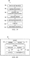
Figure 18 is an illustration of a flow diagram of a method of heating a structure using the trimmable heat blanket. -
Figure 19 is an illustration of a flow diagram of aircraft production and service methodology. -
Figure 20 is an illustration of a block diagram of an aircraft. - Referring first to
Figures 1-3 ,heating apparatus 18 in the form of a flexible,electrical heat blanket 20 is coupled by external power andcontrol lines 22 to acontroller 24 which includes a source of electrical power (not shown). Theheat blanket 20 can comprise a resistiveheating element circuit 34, which may comprise a printed flex circuit, embedded in and laminated between two layers offlexible material 38. Each of the two layers offlexible material 38 may comprise a vulcanized silicone rubber reinforced with a layer (not shown) of fiberglass. Depending on the application, theflexible material 38 may comprise latex rubber or any of various other elastomers. In still other applications, theflexible material 38 may comprise polyimide, Kapton® or other flexible films. While two layers offlexible material 38 are depicted the resistiveheating element circuit 34 may be embedded in a single layer offlexible material 38, as by insert molding. The resistiveheating element circuit 34 includes a series of later discussed electrical leads (not shown) coupled to one or more bus bars (not shown) that are connected to the external power andcontrol lines 22 via anentry tab 36 on theheat blanket 20. - In one application, shown in
Figure 2 , theblanket 20 is placed on astructure 28, such as a skin of an aircraft, overlying acomposite repair patch 30 that requires thermal curing according to a predefined cure schedule. As will be discussed below, theheat blanket 20 can be easily specifically tailored to the size and shape of arepair area 31 containing thecomposite repair patch 30. Depending on the application, one ormore thermocouples 32 may be placed beneath theheat blanket 20, immediately outside the edges of therepair patch 30. Thethermocouples 32 are coupled byelectrical lines 26 to thecontroller 24. Thecontroller 24 receives signals from thethermocouples 32 representing the sensed temperature of theheat blanket 20. Based on this sensed temperature,controller 24 adjusts AC power supplied to theheat blanket 20 in a manner that controls the temperature of theheat blanket 20 according to the cure schedule. -
Figures 4 and 5 illustrate a typical application of theflexible heat blanket 20 that has been trimmed to size. In this example, theheat blanket 20 has been trimmed to a width that wraps over and extends slightly beyond the edges of astringer 66 on askin 64, and a length that is sufficient to cover anunderlying repair area 31. Due to its flexibility, theheat blanket 20 conforms to the contour of thestringer 66 and to theskin 64. - Referring to
Figure 6 , the resistiveheating element circuit 34 may comprise an N X M, two-dimensional array 46 of individual resistiveheating element circuits 42, arranged in aligned N rows and M columns. The individual resistiveheating element circuits 42 can be substantially identical in size and shape. The resistiveheating element circuit 34 may comprise a one-dimensional array 62 (seeFigure 12 ) of individual resistiveheating element circuits 42. In the example shown inFigure 6 , the circuits are arranged in a 4 x 4 two-dimensional array 46, however thearray 46 may contain any number of individual resistiveheating element circuits 42. Additionally, while a regular,rectilinear array 46 is illustrated, the individual resistiveheating element circuits 42 may be arranged in an irregular array or in an array that is not rectilinear. Any of various array geometries are possible. Moreover, the individual resistiveheating element circuits 42 may be any size suitable for the application, and while they are identical in size in the illustrated example, the array may contain resistiveheating elements circuits 42 having differing sizes. Each of theindividual circuits 42 is independently connected by a pair of electrical lines 48 (seeFigure 6A ) to anelectrical bus 52 which in turn is connected to thecontroller 24 by a suitable electrical coupling. Thus, it may be appreciated that theindividual circuits 42 are connected to the power source in parallel with each other. Alternatively, thebus 52 may be connected to a simpleelectrical plug 50 that can be inserted into an AC power outlet (not shown). Theindividual circuits 42 are spaced apart from each other at a distance "D". Due to the alignment of theindividual circuits 42 in thearray 46, the spacing 35 between theindividual circuits 42 is substantially constant and occur at regular intervals throughout thearray 46. - The provision of
regular spacing 35 throughout thearray 46 assists a technician in trimming theheat blanket 20 trimmed to a desired shape and/or size suitable for individual applications, while maintaining electrical continuity of the electrical heating circuit. The spacing 35 between theindividual circuits 42 may not be regular. Theheat blanket 20 is trimmed to size by cutting or otherwise severing portions of theheat blanket 20 along cut lines 54 (Figure 7 ) within the spacing 35 between theindividual circuits 42. The cut lines 54 may be printed, embossed or otherwise formed on the outside surface of theheat blanket 20, thus providing a visual guide that allows a technician to cut theheat blanket 20 to the desired shape without impairing its functionality. This cutting operation may be performed using a knife, scissors or other suitable cutting devices. In the example shown inFigures 7 and8 , six of theindividual circuits 42 are cut away on thecut line 54, forming a scrap orunused section 40 that may be separated 60, leaving a trimmedheat blanket 20a having a size and shape that is tailored for the application. By following visible cut lines 54 on theheat blanket 20, the cutting operation renders thoseindividual circuits 42 inactive in theunused section 40, whileindividual circuits 42 in the trimmedheat blanket 20a each remain active since they remain electrically connected with the power source. - Attention is directed to
Figures 9-11 which illustrate another example of thetrimmable heat blanket 20. In this example, theindividual circuits 42 are connected to each other by electrical interconnect leads 56 which coupleindividual circuits 42 in a series circuit with the power source. InFigure 10 , acut line 54 has been chosen that results in eight of theindividual circuits 42 being separated 60 (Figure 11 ) from theheat blanket 20a when trimmed to size. However, cutting away these individual circuits severs several of the electrical interconnect leads 56 between theindividual circuits 42 which are to remain active. In order to maintain electrical continuity within the series circuit containing the activeindividual circuits 42,jumper wires 58 are installed where necessary to interconnect theindividual circuits 42 that have severed interconnect leads 56. -
Figures 12 and 13 illustrate another example of theheat blanket 20 in which theindividual circuits 42 are arranged as a linear, one-dimensional array 62, suitable for use in applications such as the composite repair example shown in inFigures 4 and 5 . Theindividual circuits 42 can be connected in series with each other, however, in other examples they be connected in parallel with each other, similar to the example shown in inFigure 6 . Theheat blanket 20 may be trimmed to a desired length "L" by severing it along acut line 54 within the spacing 35 between adjacent ones of theindividual circuits 42. In the series connectedcircuit 34 shown inFigure 12 , cutting theheat blanket 20 along thecut line 54 breaks electrical continuity within thecircuit 34. Referring toFigure 13 , after separating thesection 40 of unusedindividual circuits 42 from the trimmedheat blanket 20a, electrical circuit continuity is restored by connecting ajumper wire 58 between the last individual circuit in thearray 62 and the power source. In examples where theindividual sub-circuits 42 are connected in parallel with each other, rather than in series, eachsuch sub-circuit 42 is individually connected with the power source, consequently all of the sub-circuits 42 in the tailoredblanket 20a remain connected with the power source after trimming, thus obviating the need for ajumper 58. - Attention is now directed to
Figures 14-16 which illustrate a prefabricatedelectrical connector module 70 that may be used in lieu ofjumper wires 58 to reestablish electrical continuity in aheat blanket 20 that has been trimmed to size/shape. Theconnector modules 70 may be made in standard sizes so as to be geometrically compatible with a standard grid spacing and sub-circuit size for a givenheat blanket 20, such that they can be snapped onto the ends of the electrical leads 56 wherever needed to reestablish electrical continuity that has been interrupted as a result of cuts made in theheat blanket 20. Theconnector module 70 may be formed of any suitable nonconductive material such as a molded plastic that does not soften or degrade when subjected to the temperatures produced by theheat blanket 20. In the illustrated example, theconnector module 70 has a substantiallystraight body 80 and is used to connect exposed ends of electrical leads 56 (seeFigure 12 ) that have been severed as result of a trimming operation. Theconnector module 70 includes a pair of electricallyconductive sockets 72 in one side thereof which are connected together by aninternal conductor 76. Thesockets 72 are spaced apart a distance that substantially matches the distance between exposed conductor ends 68. In use, asection 82 of theblanket 20 along anedge 84 of theheat blanket 20 is stripped away using any suitable technique, exposing the conductor ends 68. Then, the conductor ends 68 are electrically reconnected by plugging them into thesockets 72 of theconnector module 70. Effectively, theconnector module 70 is "snapped" onto the exposed conductor ends 68. -
Figure 17 illustrates an alternate form of aconnector module 70 that has a substantially L-shapedbody 80, aninternal conductor 76 andelectrical sockets 72. Theelectrical sockets 72 are positioned to receive exposed conductor ends 68 on two sides ofheat blanket 20. -
Figure 18 broadly illustrates a method of making aheating apparatus 28 using thetrimmable heat blanket 20 described above. At 82, anelectrical heat blanket 20 is provided having an array of resistiveheating element circuits 42. At 84, theelectrical heat blanket 20 is trimmed to a desired size and/or shape. During the trimming operation, at least certain of the resistive heating element circuits are removed by cutting theheat blanket 20 along cut lines within spacing 35 between theindividual circuits 42. At 86, where necessary, theindividual circuits 42 are reconnected in those areas where electrical continuity has been severed as result of cuttingheat blanket 20 to the desired size and/or shape. - Further, the disclosure comprises
the following clauses: - Clause 1. A heating apparatus, comprising: a blanket; and an array of individual resistive heating element circuits inside the blanket and configured to be coupled with a source of electrical power, the individual resistive heating element circuits being spaced apart from each other and arranged to allow the blanket to be cut to a desired shape.
- Clause 2. The heating apparatus of Clause 1, wherein: the blanket includes first and second layers of flexible material, and the array of individual resistive heating element circuits are sandwiched between the first and second layers of flexible material.
- Clause 3. The heating apparatus of Clause 1 or 2, wherein the individual resistive heating element circuits are electrically coupled in parallel with each other.
- Clause 4. The heating apparatus of Clause 1, 2, or 3, wherein the individual resistive heating element circuits are electrically coupled in series with other.
-
Clause 5. The heating apparatus of one of the Clauses 1 to 4, wherein the individual resistive heating element circuits in the array thereof are substantially identical in size and shape. - Clause 6. The heating apparatus of one of the Clauses 1 to 5, wherein the array of individual resistive heating element circuits is a two-dimensional array having N rows and M columns.
- Clause 7. The heating apparatus of one of the Clauses 1 to 6, wherein the array of individual resistive heating element circuits is a one-dimensional array.
- Clause 8. The heating apparatus of one of the Clauses 1 to 7, wherein the individual resistive heating element circuits are spaced apart from each other at a spacing that is substantially constant throughout the array.
- Clause 9. A heating apparatus, comprising: a blanket; and a resistive heating circuit embedded within the blanket and configured to be coupled with a source of electrical power, the resistive heating circuit including a plurality of individual resistive heating element circuits arranged within the blanket in a configuration allowing the blanket to be cut to a desired shape while maintaining electrical continuity between the source of electrical power and the individual heating element circuits remaining in the blanket.
- Clause 10. The heating apparatus of Clause 9, wherein the blanket includes layers of vulcanized silicone rubber.
- Clause 11. The heating apparatus of Clause 9 or 10, wherein the individual resistive heating element circuits are arranged in an array and are spaced apart from each other a distance sufficient to permit the blanket to be cut along lines between the individual resistive heating element circuits.
- Clause 12. The heating apparatus of Clause 11, wherein the array includes rows and columns.
- Clause 13. The heating apparatus of one of the Clauses 9 to 12, wherein the individual resistive heating element circuits are coupled in series with each other.
- Clause 14. The heating apparatus of one of the Clauses 9 to 13, wherein the individual resistive heating element circuits are coupled in parallel with each other.
-
Clause 15. A method of making a heating apparatus, comprising: providing an electrical heat blanket having an array of individual resistive heating element circuits therein adapted to be coupled with a source of electrical power; and trimming the electrical heat blanket to a desired shape, including removing at least certain of the individual resistive heating element circuits. -
Clause 16. The method ofClause 15, wherein: cutting away at least certain of the individual resistive heating element circuits severs electrical continuity within individual resistive heating element circuits remaining in the electrical heat blanket following the trimming, and reestablishing the electrical continuity within the individual resistive heating element circuits remaining in the electrical heat blanket following the trimming. - Clause 17 The method of
Clause 16, wherein reestablishing the electrical continuity includes installing a jumper wire between two of the individual resistive heating element circuits. -
Clause 18. The method ofClause 16 or 17, wherein reestablishing the electrical continuity includes installing a jumper wire between one of the individual resistive heating element circuits and the source of electrical power. - Clause 19. The method of
Clause -
Clause 20. The method of one of theClauses 15 to 19, wherein the trimming includes cutting the electrical heat blanket along lines defined by spacing between the individual resistive heating element circuits. - The disclosure may find use in a variety of potential applications, particularly in the transportation industry, including for example, aerospace, marine, automotive applications and other application where pressurized fluid tubes, such as fuel systems and hydraulic systems in aircraft, may be used. Thus, referring now to
Figures 19 and 20 , the disclosure may be used in the context of an aircraft manufacturing and service method 88 as shown inFigure 19 and anaircraft 90 as shown inFigure 20 . Aircraft applications of the disclosure may include, for example, without limitation, thermal curing of composite repairs on various parts of theairframe 106. During pre-production, exemplary method 88 may include specification anddesign 92 of theaircraft 90 andmaterial procurement 94. During production, component andsubassembly manufacturing 96 andsystem integration 98 of theaircraft 90 takes place. Thereafter, theaircraft 90 may go through certification anddelivery 100 in order to be placed inservice 102. While in service by a customer, theaircraft 90 is scheduled for routine maintenance andservice 104, which may also include modification, reconfiguration, refurbishment, and so on. - Each of the processes of method 88 may be performed or carried out by a system integrator, a third party, and/or an operator (e.g., a customer). For the purposes of this description, a system integrator may include without limitation any number of aircraft manufacturers and major-system subcontractors; a third party may include without limitation any number of vendors, subcontractors, and suppliers; and an operator may be an airline, leasing company, military entity, service organization, and so on.
- As shown in
Figure 20 , theaircraft 90 produced by exemplary method 88 may include anairframe 106 with a plurality ofsystems 108 and an interior 110. Examples of high-level systems 108 include one or more of apropulsion system 112, anelectrical system 114, ahydraulic system 116 and anenvironmental system 118. Any number of other systems may be included. Although an aerospace example is shown, the principles of the disclosure may be applied to other industries, such as the marine and automotive industries. - Systems and methods embodied herein may be employed during any one or more of the stages of the production and service method 88. For example, components or subassemblies corresponding to
production process 96 may be fabricated or manufactured in a manner similar to components or subassemblies produced while theaircraft 90 is in service. Also, one or more apparatus examples , method examples or a combination thereof may be utilized during the production stages 96 and 98, for example, by substantially expediting assembly of or reducing the cost of anaircraft 90. Similarly, one or more of apparatus examples method examples or a combination thereof may be utilized while theaircraft 90 is in service, for example and without limitation, to maintenance andservice 104. - As used herein, the phrase "at least one of", when used with a list of items, means different combinations of one or more of the listed items may be used and only one of each item in the list may be needed. For example, "at least one of item A, item B, and item C" may include, without limitation, item A, item A and item B, or item B. This example also may include item A, item B, and item C or item B and item C. The item may be a particular object, thing, or a category. In other words, at least one of means any combination items and number of items may be used from the list but not all of the items in the list are required.
Claims (15)
- Heating apparatus (18), comprising:a blanket (20); and,an array (46) of individual resistive heating element circuits (42) inside the blanket (20) and configured to be coupled with a source of electrical power, the individual resistive heating element circuits (42) being spaced apart (35) from each other and arranged to allow the blanket (20) to be cut to a desired shape.
- The heating apparatus (18) of claim 1, wherein:the blanket (20) includes first and second layers (38) of flexible material, andthe array (46) of individual resistive heating element circuits (42) are sandwiched between the first and second layers (38) of flexible material.
- The heating apparatus (18) of the claims 1 or 2, wherein the individual resistive heating element circuits (42) are electrically coupled in parallel with each other.
- The heating apparatus (18) of the claims 1, 2, or 3, wherein the individual resistive heating element circuits (42) are electrically coupled in series with other.
- The heating apparatus of one of the claims 1 to 4, wherein the individual resistive heating element circuits (42) in the array (46) thereof are substantially identical in size and shape.
- The heating apparatus (18) of one of the claims 1 to 5, wherein the array (46) of individual resistive heating element circuits (42) is a two-dimensional array (46) having N rows and M columns.
- The heating apparatus (18) of one of the claims 1 to 6, wherein the array (46) of individual resistive heating element circuits (42) is a one-dimensional array (62).
- The heating apparatus (18) of one of the claims 1 to 7, wherein the individual resistive heating element circuits (42) are spaced apart (35) from each other at a spacing (D) that is substantially constant throughout the array (46).
- A method of making a heating apparatus (18), comprising:providing an electrical heat blanket (20) having an array (46) of individual resistive heating element circuits (42) therein adapted to be coupled with a source of electrical power; andtrimming the electrical heat blanket (20) to a desired shape (20a), including removing at least certain of the individual resistive heating element circuits (42).
- The method of claim 9, wherein:cutting away at least certain of the individual resistive heating element circuits (42) severs electrical continuity within individual resistive heating element circuits (42) remaining in the electrical heat blanket (20) following the trimming, andreestablishing the electrical continuity within the individual resistive heating element circuits (42) remaining in the electrical heat blanket (20) following the trimming.
- The method of claim 10, wherein reestablishing the electrical continuity includes installing a jumper wire (58) between two of the individual resistive heating element circuits (42).
- The method of claim 10, wherein reestablishing the electrical continuity includes installing a jumper wire (58) between one of the individual resistive heating element circuits (42) and the source of electrical power.
- The method of claim 10, wherein reestablishing the electrical continuity includes:exposing an electrical lead (68) of one of the individual resistive heating element circuits (42) by removing a portion (65) of the electrical heat blanket (20) surrounding the electrical lead (68) along an edge (84) of the heat blanket (20), andinstalling an electrical connector module (70) on the edge (84) of the heat blanket (20).
- The method of one of the claims 9 to 13, wherein the trimming includes cutting the electrical heat blanket (20) along lines (54) defined by spacing (35) between the individual resistive heating element circuits (42).
- Use of a heating apparatus according to any of the claims 1-8 for local surface heating of a structure, such as a composite repair patch on an aircraft
Applications Claiming Priority (1)
| Application Number | Priority Date | Filing Date | Title |
|---|---|---|---|
| US15/432,143 US10306709B2 (en) | 2017-02-14 | 2017-02-14 | Trimmable heat blanket and heating method |
Publications (2)
| Publication Number | Publication Date |
|---|---|
| EP3361825A1 true EP3361825A1 (en) | 2018-08-15 |
| EP3361825B1 EP3361825B1 (en) | 2023-07-05 |
Family
ID=60473415
Family Applications (1)
| Application Number | Title | Priority Date | Filing Date |
|---|---|---|---|
| EP17203822.6A Active EP3361825B1 (en) | 2017-02-14 | 2017-11-27 | Trimmable heat blanket and heating method |
Country Status (4)
| Country | Link |
|---|---|
| US (1) | US10306709B2 (en) |
| EP (1) | EP3361825B1 (en) |
| JP (1) | JP7376221B2 (en) |
| CN (1) | CN108430117B (en) |
Families Citing this family (3)
| Publication number | Priority date | Publication date | Assignee | Title |
|---|---|---|---|---|
| US11242151B2 (en) * | 2018-10-16 | 2022-02-08 | Goodrich Corporation | Method of using printed highly flexible conductive ink bus bars to transfer power to heated components |
| CN111372336B (en) * | 2020-03-25 | 2021-10-26 | 广州智慧医疗科技有限公司 | Infrared electrothermal film and preparation method thereof |
| US11498296B2 (en) * | 2020-04-28 | 2022-11-15 | The Boeing Company | Print on demand heat blanket system |
Citations (4)
| Publication number | Priority date | Publication date | Assignee | Title |
|---|---|---|---|---|
| US20020038800A1 (en) * | 2000-08-18 | 2002-04-04 | Keith Laken | Formable thermoplastic laminate heating assembly useful in heating cheese and hot fudge |
| WO2009146429A1 (en) * | 2008-05-30 | 2009-12-03 | Thermoceramix, Inc. | Radiant heating using heater coatings |
| WO2011128899A2 (en) * | 2010-04-15 | 2011-10-20 | Ofir Gilad | Adjustable electric heating mat |
| WO2017007622A1 (en) * | 2015-07-08 | 2017-01-12 | Mks Instruments, Inc. | Trimmable heater |
Family Cites Families (28)
| Publication number | Priority date | Publication date | Assignee | Title |
|---|---|---|---|---|
| US4352707A (en) | 1981-04-23 | 1982-10-05 | Grumman Aerospace Corporation | Composite repair apparatus |
| JPH01272081A (en) * | 1988-04-21 | 1989-10-31 | Matsushita Electric Ind Co Ltd | Electric blanket body and its manufacturing method |
| US5442156A (en) | 1991-04-09 | 1995-08-15 | The Boeing Company | Heating apparatus for composite structure repair |
| CN2141227Y (en) * | 1992-11-19 | 1993-09-01 | 戴希龙 | Electric heating blanket |
| US6084206A (en) * | 1997-05-28 | 2000-07-04 | The Boeing Company | Internally temperature controlled heat blanket |
| US5908573A (en) * | 1997-12-30 | 1999-06-01 | Bask Technologies Llc | Electric floor heating system |
| US20030234247A1 (en) | 2002-06-19 | 2003-12-25 | Stern Lessing S. | Methods and apparatus for a multi-zone blanket |
| CN100508666C (en) * | 2002-11-21 | 2009-07-01 | W.E.T.汽车系统股份公司 | Heater for an automotive vehicle and method of forming same |
| US20040217110A1 (en) * | 2003-04-30 | 2004-11-04 | Brent Gray | Heating blanket and methods for curing composites |
| US7083147B2 (en) * | 2004-03-11 | 2006-08-01 | The Boeing Company | Modularized insulation, systems, apparatus, and methods |
| CN2802886Y (en) * | 2005-06-21 | 2006-08-02 | 侯淳 | Electrothermal film |
| US20100024185A1 (en) * | 2007-02-21 | 2010-02-04 | United Technologies Corporation | Complete wire mesh repair with heat blanket |
| MX341552B (en) * | 2008-09-02 | 2016-08-24 | Interface Inc | Low weight carpet and carpet tile and methods of manufacture, sizing and installation. |
| US8307872B2 (en) | 2008-11-13 | 2012-11-13 | The Boeing Company | Apparatus for curing a composite structural member |
| AU2011100130B4 (en) * | 2010-02-01 | 2012-03-08 | Creative Engineers Pty Ltd | Sleeping aid |
| BR112013009266A2 (en) * | 2010-10-21 | 2016-07-26 | Interface Inc | Method of Cutting and Installing Carpet Plates on a Mass Conveyor Floor |
| GB2484965A (en) * | 2010-10-28 | 2012-05-02 | William John Finch | Low voltage heating system suitable for use in underfloor heating |
| US8546732B2 (en) | 2010-11-10 | 2013-10-01 | Lam Research Corporation | Heating plate with planar heater zones for semiconductor processing |
| US9820339B2 (en) * | 2011-09-29 | 2017-11-14 | The Boeing Company | Induction heating using induction coils in series-parallel circuits |
| CN103167645B (en) * | 2011-12-09 | 2015-06-10 | 北京富纳特创新科技有限公司 | Preparation method of heating pad |
| CN103832303A (en) * | 2012-11-26 | 2014-06-04 | W.E.T.汽车系统有限公司 | Heater for motor vehicle and forming method thereof |
| US9375884B2 (en) * | 2014-04-15 | 2016-06-28 | The Boeing Company | Optical scanner and projection apparatus for thermal management of composite repairs |
| CN203840562U (en) * | 2014-05-15 | 2014-09-17 | 常州机电职业技术学院 | Heating core of far infrared mixed-braided electric blanket |
| CN104470004A (en) * | 2014-11-04 | 2015-03-25 | 大连果壳互动科技有限公司 | Active flexible heating body and preparing method and application of active flexible heating body |
| US10470253B2 (en) | 2014-11-19 | 2019-11-05 | The Boeing Company | Coaxial smart susceptor |
| DE202014010162U1 (en) * | 2014-12-22 | 2015-03-19 | Alt Technologies B.V. | Flexible electrical conductor device |
| US20160198776A1 (en) | 2015-01-12 | 2016-07-14 | Gerbings, LLC. | Replaceable/configurable heating system for apparel |
| CN106143945B (en) * | 2015-04-02 | 2018-12-14 | 陕西飞机工业(集团)有限公司 | A kind of aircraft pressurized cabin covering repair method |
-
2017
- 2017-02-14 US US15/432,143 patent/US10306709B2/en active Active
- 2017-11-16 JP JP2017220672A patent/JP7376221B2/en active Active
- 2017-11-27 EP EP17203822.6A patent/EP3361825B1/en active Active
-
2018
- 2018-01-22 CN CN201810057571.7A patent/CN108430117B/en active Active
Patent Citations (4)
| Publication number | Priority date | Publication date | Assignee | Title |
|---|---|---|---|---|
| US20020038800A1 (en) * | 2000-08-18 | 2002-04-04 | Keith Laken | Formable thermoplastic laminate heating assembly useful in heating cheese and hot fudge |
| WO2009146429A1 (en) * | 2008-05-30 | 2009-12-03 | Thermoceramix, Inc. | Radiant heating using heater coatings |
| WO2011128899A2 (en) * | 2010-04-15 | 2011-10-20 | Ofir Gilad | Adjustable electric heating mat |
| WO2017007622A1 (en) * | 2015-07-08 | 2017-01-12 | Mks Instruments, Inc. | Trimmable heater |
Also Published As
| Publication number | Publication date |
|---|---|
| CN108430117A (en) | 2018-08-21 |
| JP2018133328A (en) | 2018-08-23 |
| US10306709B2 (en) | 2019-05-28 |
| JP7376221B2 (en) | 2023-11-08 |
| CN108430117B (en) | 2021-11-26 |
| US20180235031A1 (en) | 2018-08-16 |
| EP3361825B1 (en) | 2023-07-05 |
Similar Documents
| Publication | Publication Date | Title |
|---|---|---|
| US10021739B2 (en) | Trimmable heater | |
| EP3361825A1 (en) | Trimmable heat blanket and heating method | |
| US6084206A (en) | Internally temperature controlled heat blanket | |
| US10940651B2 (en) | Large scale smart susceptor heater blankets requiring multi zone control | |
| CN1141616A (en) | Variable watt density heating using stranded resistance wire | |
| KR101409343B1 (en) | Circuit board manufacturing method and circuit board | |
| CN113561377B (en) | Heat blanket system and method of manufacturing the same | |
| US20140326715A1 (en) | Composite structure | |
| WO2013011306A1 (en) | Method for laminating items and items obtained by the method | |
| CN110235211A (en) | Flexible conductive element and its manufacturing process | |
| EP3499645B1 (en) | Method of preparing epoxy coated bus bars for use in electrical distribution equipment | |
| US20230213132A1 (en) | Integrated Heating and Insulation System | |
| EP3531798A1 (en) | Interconnectable heating blankets | |
| CA3170406A1 (en) | Heating mat with multiple discrete circuits | |
| CN1255824A (en) | Distribution for heating combined printed circuit board | |
| KR20250040396A (en) | Heating apparatus | |
| CN118175723A (en) | Part including a thin film on the surface of which an electronic circuit having connection terminals is integrated and a method for repairing such a part | |
| GB2397954A (en) | Integrated flex substrate metallurgical bonding | |
| JP2005093267A (en) | Branch structure of flat harness and manufacturing method thereof |
Legal Events
| Date | Code | Title | Description |
|---|---|---|---|
| PUAI | Public reference made under article 153(3) epc to a published international application that has entered the european phase |
Free format text: ORIGINAL CODE: 0009012 |
|
| STAA | Information on the status of an ep patent application or granted ep patent |
Free format text: STATUS: REQUEST FOR EXAMINATION WAS MADE |
|
| 17P | Request for examination filed |
Effective date: 20171127 |
|
| AK | Designated contracting states |
Kind code of ref document: A1 Designated state(s): AL AT BE BG CH CY CZ DE DK EE ES FI FR GB GR HR HU IE IS IT LI LT LU LV MC MK MT NL NO PL PT RO RS SE SI SK SM TR |
|
| AX | Request for extension of the european patent |
Extension state: BA ME |
|
| STAA | Information on the status of an ep patent application or granted ep patent |
Free format text: STATUS: EXAMINATION IS IN PROGRESS |
|
| 17Q | First examination report despatched |
Effective date: 20191211 |
|
| GRAP | Despatch of communication of intention to grant a patent |
Free format text: ORIGINAL CODE: EPIDOSNIGR1 |
|
| STAA | Information on the status of an ep patent application or granted ep patent |
Free format text: STATUS: GRANT OF PATENT IS INTENDED |
|
| INTG | Intention to grant announced |
Effective date: 20210120 |
|
| GRAJ | Information related to disapproval of communication of intention to grant by the applicant or resumption of examination proceedings by the epo deleted |
Free format text: ORIGINAL CODE: EPIDOSDIGR1 |
|
| STAA | Information on the status of an ep patent application or granted ep patent |
Free format text: STATUS: EXAMINATION IS IN PROGRESS |
|
| INTC | Intention to grant announced (deleted) | ||
| GRAP | Despatch of communication of intention to grant a patent |
Free format text: ORIGINAL CODE: EPIDOSNIGR1 |
|
| STAA | Information on the status of an ep patent application or granted ep patent |
Free format text: STATUS: GRANT OF PATENT IS INTENDED |
|
| INTG | Intention to grant announced |
Effective date: 20230127 |
|
| RAP3 | Party data changed (applicant data changed or rights of an application transferred) |
Owner name: THE BOEING COMPANY |
|
| GRAS | Grant fee paid |
Free format text: ORIGINAL CODE: EPIDOSNIGR3 |
|
| GRAA | (expected) grant |
Free format text: ORIGINAL CODE: 0009210 |
|
| STAA | Information on the status of an ep patent application or granted ep patent |
Free format text: STATUS: THE PATENT HAS BEEN GRANTED |
|
| AK | Designated contracting states |
Kind code of ref document: B1 Designated state(s): AL AT BE BG CH CY CZ DE DK EE ES FI FR GB GR HR HU IE IS IT LI LT LU LV MC MK MT NL NO PL PT RO RS SE SI SK SM TR |
|
| REG | Reference to a national code |
Ref country code: CH Ref legal event code: EP |
|
| REG | Reference to a national code |
Ref country code: AT Ref legal event code: REF Ref document number: 1586011 Country of ref document: AT Kind code of ref document: T Effective date: 20230715 |
|
| REG | Reference to a national code |
Ref country code: DE Ref legal event code: R096 Ref document number: 602017070887 Country of ref document: DE |
|
| REG | Reference to a national code |
Ref country code: IE Ref legal event code: FG4D |
|
| P01 | Opt-out of the competence of the unified patent court (upc) registered |
Effective date: 20230703 |
|
| REG | Reference to a national code |
Ref country code: LT Ref legal event code: MG9D |
|
| REG | Reference to a national code |
Ref country code: NL Ref legal event code: MP Effective date: 20230705 |
|
| REG | Reference to a national code |
Ref country code: AT Ref legal event code: MK05 Ref document number: 1586011 Country of ref document: AT Kind code of ref document: T Effective date: 20230705 |
|
| PG25 | Lapsed in a contracting state [announced via postgrant information from national office to epo] |
Ref country code: NL Free format text: LAPSE BECAUSE OF FAILURE TO SUBMIT A TRANSLATION OF THE DESCRIPTION OR TO PAY THE FEE WITHIN THE PRESCRIBED TIME-LIMIT Effective date: 20230705 |
|
| PG25 | Lapsed in a contracting state [announced via postgrant information from national office to epo] |
Ref country code: GR Free format text: LAPSE BECAUSE OF FAILURE TO SUBMIT A TRANSLATION OF THE DESCRIPTION OR TO PAY THE FEE WITHIN THE PRESCRIBED TIME-LIMIT Effective date: 20231006 |
|
| PG25 | Lapsed in a contracting state [announced via postgrant information from national office to epo] |
Ref country code: ES Free format text: LAPSE BECAUSE OF FAILURE TO SUBMIT A TRANSLATION OF THE DESCRIPTION OR TO PAY THE FEE WITHIN THE PRESCRIBED TIME-LIMIT Effective date: 20230705 |
|
| PG25 | Lapsed in a contracting state [announced via postgrant information from national office to epo] |
Ref country code: IS Free format text: LAPSE BECAUSE OF FAILURE TO SUBMIT A TRANSLATION OF THE DESCRIPTION OR TO PAY THE FEE WITHIN THE PRESCRIBED TIME-LIMIT Effective date: 20231105 |
|
| PG25 | Lapsed in a contracting state [announced via postgrant information from national office to epo] |
Ref country code: SE Free format text: LAPSE BECAUSE OF FAILURE TO SUBMIT A TRANSLATION OF THE DESCRIPTION OR TO PAY THE FEE WITHIN THE PRESCRIBED TIME-LIMIT Effective date: 20230705 Ref country code: RS Free format text: LAPSE BECAUSE OF FAILURE TO SUBMIT A TRANSLATION OF THE DESCRIPTION OR TO PAY THE FEE WITHIN THE PRESCRIBED TIME-LIMIT Effective date: 20230705 Ref country code: PT Free format text: LAPSE BECAUSE OF FAILURE TO SUBMIT A TRANSLATION OF THE DESCRIPTION OR TO PAY THE FEE WITHIN THE PRESCRIBED TIME-LIMIT Effective date: 20231106 Ref country code: NO Free format text: LAPSE BECAUSE OF FAILURE TO SUBMIT A TRANSLATION OF THE DESCRIPTION OR TO PAY THE FEE WITHIN THE PRESCRIBED TIME-LIMIT Effective date: 20231005 Ref country code: LV Free format text: LAPSE BECAUSE OF FAILURE TO SUBMIT A TRANSLATION OF THE DESCRIPTION OR TO PAY THE FEE WITHIN THE PRESCRIBED TIME-LIMIT Effective date: 20230705 Ref country code: LT Free format text: LAPSE BECAUSE OF FAILURE TO SUBMIT A TRANSLATION OF THE DESCRIPTION OR TO PAY THE FEE WITHIN THE PRESCRIBED TIME-LIMIT Effective date: 20230705 Ref country code: IS Free format text: LAPSE BECAUSE OF FAILURE TO SUBMIT A TRANSLATION OF THE DESCRIPTION OR TO PAY THE FEE WITHIN THE PRESCRIBED TIME-LIMIT Effective date: 20231105 Ref country code: HR Free format text: LAPSE BECAUSE OF FAILURE TO SUBMIT A TRANSLATION OF THE DESCRIPTION OR TO PAY THE FEE WITHIN THE PRESCRIBED TIME-LIMIT Effective date: 20230705 Ref country code: GR Free format text: LAPSE BECAUSE OF FAILURE TO SUBMIT A TRANSLATION OF THE DESCRIPTION OR TO PAY THE FEE WITHIN THE PRESCRIBED TIME-LIMIT Effective date: 20231006 Ref country code: FI Free format text: LAPSE BECAUSE OF FAILURE TO SUBMIT A TRANSLATION OF THE DESCRIPTION OR TO PAY THE FEE WITHIN THE PRESCRIBED TIME-LIMIT Effective date: 20230705 Ref country code: ES Free format text: LAPSE BECAUSE OF FAILURE TO SUBMIT A TRANSLATION OF THE DESCRIPTION OR TO PAY THE FEE WITHIN THE PRESCRIBED TIME-LIMIT Effective date: 20230705 Ref country code: AT Free format text: LAPSE BECAUSE OF FAILURE TO SUBMIT A TRANSLATION OF THE DESCRIPTION OR TO PAY THE FEE WITHIN THE PRESCRIBED TIME-LIMIT Effective date: 20230705 |
|
| PG25 | Lapsed in a contracting state [announced via postgrant information from national office to epo] |
Ref country code: PL Free format text: LAPSE BECAUSE OF FAILURE TO SUBMIT A TRANSLATION OF THE DESCRIPTION OR TO PAY THE FEE WITHIN THE PRESCRIBED TIME-LIMIT Effective date: 20230705 |
|
| REG | Reference to a national code |
Ref country code: DE Ref legal event code: R097 Ref document number: 602017070887 Country of ref document: DE |
|
| PG25 | Lapsed in a contracting state [announced via postgrant information from national office to epo] |
Ref country code: SM Free format text: LAPSE BECAUSE OF FAILURE TO SUBMIT A TRANSLATION OF THE DESCRIPTION OR TO PAY THE FEE WITHIN THE PRESCRIBED TIME-LIMIT Effective date: 20230705 Ref country code: RO Free format text: LAPSE BECAUSE OF FAILURE TO SUBMIT A TRANSLATION OF THE DESCRIPTION OR TO PAY THE FEE WITHIN THE PRESCRIBED TIME-LIMIT Effective date: 20230705 Ref country code: EE Free format text: LAPSE BECAUSE OF FAILURE TO SUBMIT A TRANSLATION OF THE DESCRIPTION OR TO PAY THE FEE WITHIN THE PRESCRIBED TIME-LIMIT Effective date: 20230705 Ref country code: DK Free format text: LAPSE BECAUSE OF FAILURE TO SUBMIT A TRANSLATION OF THE DESCRIPTION OR TO PAY THE FEE WITHIN THE PRESCRIBED TIME-LIMIT Effective date: 20230705 Ref country code: CZ Free format text: LAPSE BECAUSE OF FAILURE TO SUBMIT A TRANSLATION OF THE DESCRIPTION OR TO PAY THE FEE WITHIN THE PRESCRIBED TIME-LIMIT Effective date: 20230705 Ref country code: SK Free format text: LAPSE BECAUSE OF FAILURE TO SUBMIT A TRANSLATION OF THE DESCRIPTION OR TO PAY THE FEE WITHIN THE PRESCRIBED TIME-LIMIT Effective date: 20230705 |
|
| PLBE | No opposition filed within time limit |
Free format text: ORIGINAL CODE: 0009261 |
|
| STAA | Information on the status of an ep patent application or granted ep patent |
Free format text: STATUS: NO OPPOSITION FILED WITHIN TIME LIMIT |
|
| PG25 | Lapsed in a contracting state [announced via postgrant information from national office to epo] |
Ref country code: IT Free format text: LAPSE BECAUSE OF FAILURE TO SUBMIT A TRANSLATION OF THE DESCRIPTION OR TO PAY THE FEE WITHIN THE PRESCRIBED TIME-LIMIT Effective date: 20230705 |
|
| 26N | No opposition filed |
Effective date: 20240408 |
|
| REG | Reference to a national code |
Ref country code: CH Ref legal event code: PL |
|
| PG25 | Lapsed in a contracting state [announced via postgrant information from national office to epo] |
Ref country code: MC Free format text: LAPSE BECAUSE OF FAILURE TO SUBMIT A TRANSLATION OF THE DESCRIPTION OR TO PAY THE FEE WITHIN THE PRESCRIBED TIME-LIMIT Effective date: 20230705 |
|
| PG25 | Lapsed in a contracting state [announced via postgrant information from national office to epo] |
Ref country code: LU Free format text: LAPSE BECAUSE OF NON-PAYMENT OF DUE FEES Effective date: 20231127 |
|
| PG25 | Lapsed in a contracting state [announced via postgrant information from national office to epo] |
Ref country code: CH Free format text: LAPSE BECAUSE OF NON-PAYMENT OF DUE FEES Effective date: 20231130 |
|
| PG25 | Lapsed in a contracting state [announced via postgrant information from national office to epo] |
Ref country code: MC Free format text: LAPSE BECAUSE OF FAILURE TO SUBMIT A TRANSLATION OF THE DESCRIPTION OR TO PAY THE FEE WITHIN THE PRESCRIBED TIME-LIMIT Effective date: 20230705 Ref country code: LU Free format text: LAPSE BECAUSE OF NON-PAYMENT OF DUE FEES Effective date: 20231127 Ref country code: CH Free format text: LAPSE BECAUSE OF NON-PAYMENT OF DUE FEES Effective date: 20231130 Ref country code: SI Free format text: LAPSE BECAUSE OF FAILURE TO SUBMIT A TRANSLATION OF THE DESCRIPTION OR TO PAY THE FEE WITHIN THE PRESCRIBED TIME-LIMIT Effective date: 20230705 |
|
| REG | Reference to a national code |
Ref country code: BE Ref legal event code: MM Effective date: 20231130 |
|
| REG | Reference to a national code |
Ref country code: IE Ref legal event code: MM4A |
|
| PG25 | Lapsed in a contracting state [announced via postgrant information from national office to epo] |
Ref country code: IE Free format text: LAPSE BECAUSE OF NON-PAYMENT OF DUE FEES Effective date: 20231127 |
|
| PG25 | Lapsed in a contracting state [announced via postgrant information from national office to epo] |
Ref country code: BE Free format text: LAPSE BECAUSE OF NON-PAYMENT OF DUE FEES Effective date: 20231130 |
|
| PG25 | Lapsed in a contracting state [announced via postgrant information from national office to epo] |
Ref country code: IE Free format text: LAPSE BECAUSE OF NON-PAYMENT OF DUE FEES Effective date: 20231127 Ref country code: BE Free format text: LAPSE BECAUSE OF NON-PAYMENT OF DUE FEES Effective date: 20231130 |
|
| PG25 | Lapsed in a contracting state [announced via postgrant information from national office to epo] |
Ref country code: BG Free format text: LAPSE BECAUSE OF FAILURE TO SUBMIT A TRANSLATION OF THE DESCRIPTION OR TO PAY THE FEE WITHIN THE PRESCRIBED TIME-LIMIT Effective date: 20230705 |
|
| PG25 | Lapsed in a contracting state [announced via postgrant information from national office to epo] |
Ref country code: BG Free format text: LAPSE BECAUSE OF FAILURE TO SUBMIT A TRANSLATION OF THE DESCRIPTION OR TO PAY THE FEE WITHIN THE PRESCRIBED TIME-LIMIT Effective date: 20230705 |
|
| PG25 | Lapsed in a contracting state [announced via postgrant information from national office to epo] |
Ref country code: CY Free format text: LAPSE BECAUSE OF FAILURE TO SUBMIT A TRANSLATION OF THE DESCRIPTION OR TO PAY THE FEE WITHIN THE PRESCRIBED TIME-LIMIT; INVALID AB INITIO Effective date: 20171127 |
|
| PG25 | Lapsed in a contracting state [announced via postgrant information from national office to epo] |
Ref country code: HU Free format text: LAPSE BECAUSE OF FAILURE TO SUBMIT A TRANSLATION OF THE DESCRIPTION OR TO PAY THE FEE WITHIN THE PRESCRIBED TIME-LIMIT; INVALID AB INITIO Effective date: 20171127 |
|
| PG25 | Lapsed in a contracting state [announced via postgrant information from national office to epo] |
Ref country code: TR Free format text: LAPSE BECAUSE OF FAILURE TO SUBMIT A TRANSLATION OF THE DESCRIPTION OR TO PAY THE FEE WITHIN THE PRESCRIBED TIME-LIMIT Effective date: 20230705 |
|
| PGFP | Annual fee paid to national office [announced via postgrant information from national office to epo] |
Ref country code: DE Payment date: 20251128 Year of fee payment: 9 |
|
| PGFP | Annual fee paid to national office [announced via postgrant information from national office to epo] |
Ref country code: GB Payment date: 20251127 Year of fee payment: 9 |
|
| PGFP | Annual fee paid to national office [announced via postgrant information from national office to epo] |
Ref country code: FR Payment date: 20251125 Year of fee payment: 9 |